CN1158889C - Method and apparatus for providing diversity in hard handoff for CDMA system - Google Patents
Method and apparatus for providing diversity in hard handoff for CDMA system Download PDFInfo
- Publication number
- CN1158889C CN1158889C CNB971965862A CN97196586A CN1158889C CN 1158889 C CN1158889 C CN 1158889C CN B971965862 A CNB971965862 A CN B971965862A CN 97196586 A CN97196586 A CN 97196586A CN 1158889 C CN1158889 C CN 1158889C
- Authority
- CN
- China
- Prior art keywords
- base station
- remote unit
- overlay area
- antenna
- signal
- Prior art date
- Legal status (The legal status is an assumption and is not a legal conclusion. Google has not performed a legal analysis and makes no representation as to the accuracy of the status listed.)
- Expired - Lifetime
Links
- 238000000034 method Methods 0.000 title claims description 121
- 238000004891 communication Methods 0.000 claims abstract description 243
- 230000007423 decrease Effects 0.000 claims description 22
- 238000001228 spectrum Methods 0.000 claims description 20
- 230000008859 change Effects 0.000 claims description 10
- 230000008569 process Effects 0.000 claims description 7
- 230000001360 synchronised effect Effects 0.000 claims 4
- 230000003111 delayed effect Effects 0.000 abstract description 6
- 230000001934 delay Effects 0.000 abstract description 2
- 238000005516 engineering process Methods 0.000 description 23
- 230000008901 benefit Effects 0.000 description 18
- 238000012545 processing Methods 0.000 description 18
- 230000001413 cellular effect Effects 0.000 description 17
- 230000005540 biological transmission Effects 0.000 description 16
- 238000006243 chemical reaction Methods 0.000 description 15
- 230000014509 gene expression Effects 0.000 description 15
- 230000009471 action Effects 0.000 description 13
- 238000005259 measurement Methods 0.000 description 13
- 230000002441 reversible effect Effects 0.000 description 12
- 230000010267 cellular communication Effects 0.000 description 9
- 238000001514 detection method Methods 0.000 description 9
- 230000006870 function Effects 0.000 description 7
- 238000013439 planning Methods 0.000 description 6
- 238000010586 diagram Methods 0.000 description 5
- 238000005562 fading Methods 0.000 description 5
- 238000012546 transfer Methods 0.000 description 5
- 230000007704 transition Effects 0.000 description 5
- 238000013461 design Methods 0.000 description 4
- 230000000694 effects Effects 0.000 description 4
- 230000007246 mechanism Effects 0.000 description 4
- 230000004044 response Effects 0.000 description 4
- 230000002411 adverse Effects 0.000 description 3
- 230000005012 migration Effects 0.000 description 3
- 238000013508 migration Methods 0.000 description 3
- 230000008054 signal transmission Effects 0.000 description 3
- 238000013316 zoning Methods 0.000 description 3
- 230000002349 favourable effect Effects 0.000 description 2
- 239000013307 optical fiber Substances 0.000 description 2
- 235000016936 Dendrocalamus strictus Nutrition 0.000 description 1
- 235000012364 Peperomia pellucida Nutrition 0.000 description 1
- 240000007711 Peperomia pellucida Species 0.000 description 1
- 238000009825 accumulation Methods 0.000 description 1
- 230000003416 augmentation Effects 0.000 description 1
- 230000004888 barrier function Effects 0.000 description 1
- 230000033228 biological regulation Effects 0.000 description 1
- 238000004364 calculation method Methods 0.000 description 1
- 230000015556 catabolic process Effects 0.000 description 1
- 230000001427 coherent effect Effects 0.000 description 1
- 238000005094 computer simulation Methods 0.000 description 1
- 238000006731 degradation reaction Methods 0.000 description 1
- 230000006866 deterioration Effects 0.000 description 1
- 238000011161 development Methods 0.000 description 1
- 230000003292 diminished effect Effects 0.000 description 1
- 230000005284 excitation Effects 0.000 description 1
- 238000007689 inspection Methods 0.000 description 1
- 238000009434 installation Methods 0.000 description 1
- 230000004807 localization Effects 0.000 description 1
- 238000007726 management method Methods 0.000 description 1
- 238000013507 mapping Methods 0.000 description 1
- 230000006855 networking Effects 0.000 description 1
- 230000002085 persistent effect Effects 0.000 description 1
- 229920001200 poly(ethylene-vinyl acetate) Polymers 0.000 description 1
- 238000012797 qualification Methods 0.000 description 1
- 230000005855 radiation Effects 0.000 description 1
- 238000002310 reflectometry Methods 0.000 description 1
- 230000029058 respiratory gaseous exchange Effects 0.000 description 1
- 230000000717 retained effect Effects 0.000 description 1
- 238000012552 review Methods 0.000 description 1
- 238000000926 separation method Methods 0.000 description 1
- GOLXNESZZPUPJE-UHFFFAOYSA-N spiromesifen Chemical compound CC1=CC(C)=CC(C)=C1C(C(O1)=O)=C(OC(=O)CC(C)(C)C)C11CCCC1 GOLXNESZZPUPJE-UHFFFAOYSA-N 0.000 description 1
- 238000006467 substitution reaction Methods 0.000 description 1
- 230000001960 triggered effect Effects 0.000 description 1
Images


Classifications
-
- H—ELECTRICITY
- H04—ELECTRIC COMMUNICATION TECHNIQUE
- H04B—TRANSMISSION
- H04B7/00—Radio transmission systems, i.e. using radiation field
- H04B7/02—Diversity systems; Multi-antenna system, i.e. transmission or reception using multiple antennas
- H04B7/04—Diversity systems; Multi-antenna system, i.e. transmission or reception using multiple antennas using two or more spaced independent antennas
- H04B7/06—Diversity systems; Multi-antenna system, i.e. transmission or reception using multiple antennas using two or more spaced independent antennas at the transmitting station
- H04B7/0613—Diversity systems; Multi-antenna system, i.e. transmission or reception using multiple antennas using two or more spaced independent antennas at the transmitting station using simultaneous transmission
- H04B7/0667—Diversity systems; Multi-antenna system, i.e. transmission or reception using multiple antennas using two or more spaced independent antennas at the transmitting station using simultaneous transmission of delayed versions of same signal
- H04B7/0671—Diversity systems; Multi-antenna system, i.e. transmission or reception using multiple antennas using two or more spaced independent antennas at the transmitting station using simultaneous transmission of delayed versions of same signal using different delays between antennas
-
- H—ELECTRICITY
- H04—ELECTRIC COMMUNICATION TECHNIQUE
- H04B—TRANSMISSION
- H04B7/00—Radio transmission systems, i.e. using radiation field
- H04B7/02—Diversity systems; Multi-antenna system, i.e. transmission or reception using multiple antennas
- H04B7/022—Site diversity; Macro-diversity
-
- H—ELECTRICITY
- H04—ELECTRIC COMMUNICATION TECHNIQUE
- H04B—TRANSMISSION
- H04B7/00—Radio transmission systems, i.e. using radiation field
- H04B7/24—Radio transmission systems, i.e. using radiation field for communication between two or more posts
- H04B7/26—Radio transmission systems, i.e. using radiation field for communication between two or more posts at least one of which is mobile
- H04B7/2603—Arrangements for wireless physical layer control
- H04B7/2606—Arrangements for base station coverage control, e.g. by using relays in tunnels
-
- H—ELECTRICITY
- H04—ELECTRIC COMMUNICATION TECHNIQUE
- H04W—WIRELESS COMMUNICATION NETWORKS
- H04W36/00—Hand-off or reselection arrangements
- H04W36/16—Performing reselection for specific purposes
- H04W36/18—Performing reselection for specific purposes for allowing seamless reselection, e.g. soft reselection
-
- H—ELECTRICITY
- H04—ELECTRIC COMMUNICATION TECHNIQUE
- H04W—WIRELESS COMMUNICATION NETWORKS
- H04W52/00—Power management, e.g. TPC [Transmission Power Control], power saving or power classes
- H04W52/04—TPC
- H04W52/38—TPC being performed in particular situations
- H04W52/42—TPC being performed in particular situations in systems with time, space, frequency or polarisation diversity
-
- H—ELECTRICITY
- H04—ELECTRIC COMMUNICATION TECHNIQUE
- H04W—WIRELESS COMMUNICATION NETWORKS
- H04W16/00—Network planning, e.g. coverage or traffic planning tools; Network deployment, e.g. resource partitioning or cells structures
- H04W16/24—Cell structures
- H04W16/26—Cell enhancers or enhancement, e.g. for tunnels, building shadow
-
- H—ELECTRICITY
- H04—ELECTRIC COMMUNICATION TECHNIQUE
- H04W—WIRELESS COMMUNICATION NETWORKS
- H04W52/00—Power management, e.g. TPC [Transmission Power Control], power saving or power classes
- H04W52/02—Power saving arrangements
- H04W52/0203—Power saving arrangements in the radio access network or backbone network of wireless communication networks
-
- H—ELECTRICITY
- H04—ELECTRIC COMMUNICATION TECHNIQUE
- H04W—WIRELESS COMMUNICATION NETWORKS
- H04W52/00—Power management, e.g. TPC [Transmission Power Control], power saving or power classes
- H04W52/04—TPC
- H04W52/06—TPC algorithms
- H04W52/16—Deriving transmission power values from another channel
-
- Y—GENERAL TAGGING OF NEW TECHNOLOGICAL DEVELOPMENTS; GENERAL TAGGING OF CROSS-SECTIONAL TECHNOLOGIES SPANNING OVER SEVERAL SECTIONS OF THE IPC; TECHNICAL SUBJECTS COVERED BY FORMER USPC CROSS-REFERENCE ART COLLECTIONS [XRACs] AND DIGESTS
- Y02—TECHNOLOGIES OR APPLICATIONS FOR MITIGATION OR ADAPTATION AGAINST CLIMATE CHANGE
- Y02D—CLIMATE CHANGE MITIGATION TECHNOLOGIES IN INFORMATION AND COMMUNICATION TECHNOLOGIES [ICT], I.E. INFORMATION AND COMMUNICATION TECHNOLOGIES AIMING AT THE REDUCTION OF THEIR OWN ENERGY USE
- Y02D30/00—Reducing energy consumption in communication networks
- Y02D30/70—Reducing energy consumption in communication networks in wireless communication networks
Landscapes
- Engineering & Computer Science (AREA)
- Computer Networks & Wireless Communication (AREA)
- Signal Processing (AREA)
- Mobile Radio Communication Systems (AREA)
- Radio Transmission System (AREA)
- Radio Relay Systems (AREA)
- Input Circuits Of Receivers And Coupling Of Receivers And Audio Equipment (AREA)
Abstract
In a communications network, a network user communicates using a remote unit (125) with another user (30) via at least one base station (B1A). The communications network has a first base station (B1A) having a first coverage area and a second base station (B2A) having a second coverage area. In the situation where communication is not established between the second base station (B2A) and the remote unit (125), in order to provide communication between the remote unit (125) and the first base station (B1A) when the remote unit (125) is in the first coverage and simultaneously in the second coverage area, the first base station (B1A) produces a first active communication signal as intended for the remote unit (125). The first base station transmits the first active communication signal from a first antenna (130). The base station delays the first active communication signal to produce a first delayed active communication signal and transmits it from a second antenna (135) wherein the second antenna (135) is oriented with respect to the first antenna (130) such that the first active communication signal and the first delayed active communication signal fade independently as perceived by the remote unit. The first base station (B1A) may measure a round trip delay of the first active communication signal in order to identify that the remote unit (125) is located within the second coverage area.
Description
Technical field
The present invention relates generally to be provided with the cellular communication system of many base stations.The invention particularly relates to technology novel and switching communication between improved base station at different cellular systems.
Background technology
Utilize code division multiple access (CDMA) modulation technique just to realize having one of several technology of the communication of a large amount of system users.Though known have other technology, for example time division multiple access (TDMA) and frequency division multiple access (FDMA), other modulation technique of CDMA and these has been compared significant advantage.In U.S. Patent No. 4,901,307, name is called to have disclosed in " the spread spectrum multiple access communication system of utilizing satellite or land-based repeaters " uses CDMA technology in multi-address communication system, and this patent has transferred assignee of the present invention, the content of its announcement is incorporated herein, as a reference.
In above-mentioned patent, disclosed a kind of multiple access technology, in this technology, each has transceiver (being also referred to as remote unit) a large amount of mobile telephone system users, and transponder or ground base station (being also referred to as base station or station, unit) utilize CDMA spread spectrum communication signal to communicate via satellite for they.When using cdma communication, can reuse frequency spectrum repeatedly.The result who uses CDMA technology can obtain the much higher spectrum efficiency that Billy realizes with other multiple access technology, therefore, can improve system user capacity.
The traditional F M cell phone system that the U.S. uses is commonly referred to as advanced mobile phone service (AMPS), in the standard EIA/TIA-553 of Electronic Industries Association " mobile radio station-land based station compatibility specification " detailed description is arranged.In a kind of like this traditional F M cell phone system, available band is divided into the channel that bandwidth is generally 30 kilo hertzs (kHz).Geographically system service area is divided into the base station coverage area that size can change.Available channel is divided in groups.These these overlay areas of frequency component dispensing, so that the possibility minimum of co-channel interference.For example, consider a kind of like this system, it has seven group of frequencies, and the overlay area is divided into hexagon.The used group of frequencies in the group of frequencies of using in overlay area and six the most contiguous overlay areas is different.
In traditional cellular system, when remote unit is crossed over the border of overlay area of two different base stations, make with handover scheme to communicate to connect continuation.In the AMPS system, the switching from a base station to another base station is the receiver in handling effective base station of call communication, and the received signal intensity decreases of perceiving this distant station begins when being lower than predetermined threshold.The low signal intensity indication means that remote unit is near the edge, overlay area of this base station.When signal level drops to when being lower than predetermined threshold, effectively the base station just requires system controller to determine whether neighbor base station receives the signal strength signal intensity of signal of this distant station better than current base station.
System controller sends the message of handoff request to neighbor base station in response to the inquiry of effective base station.The base station special radio scanner of use of each contiguous effective base station is searched for the signal from distant station on the working channel of this distant station.If there is a base station to receive the appropriate signals level in the neighbor base station, then just attempt switching to the neighbor base station that is noted as target BS now to the system controller report.Then, from the used channel group of target BS, select an idle channel to begin to switch.The control message is sent to this remote unit, order the new channel that it supports from current channel switch to target BS.Simultaneously, system controller connects conversation from converting into target base station, effective base station.This processing is called direct-cut operation.Term " firmly " is used to represent the feature of ' the disconnecting before connecting ' of switching.
In legacy system, if unsuccessful to the switching of target BS, conversation connects will lose (promptly disconnecting).The direct-cut operation fault occurs many reasons are arranged.If in target BS, there is not available idle channel, can produce handoff failure.If one of neighbor base station report receives signal from this remote unit, and in fact this base station reality is receiving the different remote units that utilize same channel and the base station communication of distant place, also can produce handoff failure.The result of this reporting errors connects conversation to be transformed on the wrong base station, and generally the signal strength signal intensity of the actual remote unit that receives of this base station is not enough to keep communication.And, if remote unit does not receive the order of translated channel, switch and also will fail.Actual operating experience shows that handoff failure often takes place, and has reduced the reliability of system significantly.
Another total problem of tradition AMPS telephone system occurs in after the boundary vicinity of remote unit between two overlay areas stay a period of time.Under this situation, when remote unit changed the position, when perhaps other reflection in this overlay area or decay thing changed the position, signal level was fluctuating with respect to each base station.The result of the fluctuation of signal level can cause " table tennis " state to occur, and in this state, is created in the request of handoff calls back and forth between two base stations repeatedly.This subsidiary unnecessary switching has increased the possibility that conversation is disconnected carelessly.In addition, even switching repeatedly, success also may be unfavorable for signal quality.
In U.S. Patent No. 5,101,501, name is called " method and system that communication is carried out soft handover in the cdma cellular telephone system " and (announces on March 31st, 1992, be transferred to assignee of the present invention) in, disclosed a kind of method and system, during switching the CDMA conversation, communicated by more than one base station and remote unit.In cellular system, communicate by letter when target BS switches from effective base station and can not be interrupted with such switching.Such switching can be called " soft " switches, with the communication disruption of first effective base station before, set up simultaneously with target BS and to communicate by letter, make target BS become second effective base station.
In U.S. Patent No. 5,267,261, name is called in " mobile radio station of soft handover in the cdma cellular communication system " (on November 30th, 1993 bulletin, hereinafter be called " 261 patent ", this patent also transfers assignee of the present invention) and has disclosed a kind of improved soft hand-off.In the system of ' 261 patent ', according to the measurement of remote unit to " pilot tone " signal strength signal intensity of each base station in the system, the processing of control soft handover.These pilot frequency intensity measurings help soft handover to handle.Be convenient to determine available base station handoff candidate.
More particularly, in the system of ' 261 patent ', the signal strength signal intensity of remote unit monitors neighbor base station pilot signal.The overlay area of neighbor base station does not need actual vicinity to set up the overlay area of the base station of efficient communication.When the signal strength signal intensity of the pilot signal that records a neighbor base station surpasses given threshold value, this remote unit just by effective base station to system controller strength of transmitted signals message.System controller instruction target BS is set up with this remote unit and is communicated by letter, and sets up communication by this remote unit of effective base station command simultaneously by target BS, keeps simultaneously and the communicating by letter of effective base station.This processing can continue addition of base station.
When remote unit drops to when being lower than predetermined level to the signal strength signal intensity corresponding to the pilot tone of one of base station by its Channel Detection of communicating by letter, the signal strength signal intensity of the corresponding base station that remote unit just records to the system controller report by effective base station.System controller sends command message to base station of identifying and remote unit, by interrupting the base station communication by identifying, keeps the communication by other effective base station or base station simultaneously.
Though above-mentioned technology is suitable for well by the Call Transfer between the base station in the same cellular system of same system controller control, remote unit more difficult situation can occur when moving to the overlay area of base station services of another cellular system.The complicated factor that switches such as " between system " be each system by different system controller control, between the system controller of the base station of first system and second system, do not have direct link usually, vice versa.Thereby, stoped two systems during hand-off process, to carry out remote unit communication by more than one base station simultaneously.Link can be used for inter-system soft handoff between system even exist between two systems, and it is complicated that the different characteristic that two systems often occur also further makes soft handover handle.
When resource can not be used for carrying out inter-system soft handoff, if keep service not interrupt, then the conversation connection must be carried out " firmly " switching from a system to another system.Switch between system and must on time that might make conversation successful connection ground conversion between system and position, carry out.This has caused switching should be only attempts under below the situation, for example:
(I) idle channel is arranged in target BS,
(ii) remote unit is at target BS with effectively in the scope of base station, and
Guarantee that (iii) the residing position of remote unit can receive the order of translated channel.
Ideally, direct-cut operation should carry out in such a way between each this system, makes the possibility minimum that occurs " table tennis " handoff request between the base station of different system.
These and other some shortcoming of handoff technique have reduced the quality of cellular communication between existed system, can expect, when cellular system continues to enlarge, will further make performance degradation.Therefore, consequently need the handoff technique between a kind of system, the switching of between the base station of different system, conversing reliably.
Summary of the invention
Code division multiple access (CDMA) to CDMA with an aspect of direct-cut operation frequently is, a large amount of pass through it and can not handle when setting up the signal of base station energy of communicating by letter by soft handover existing, and must keep being connected between remote unit and base station.As remote unit was felt, disabled signal energy had reduced the signal to noise ratio of signal.If signal declines with respect to effective base station, signal to noise ratio is reduced.Therefore, a kind of method of improving performance is the possibility minimum that makes with respect to the deep fading of effective base station.The invention provides a kind of forward link frequency spectrum diversity, from twice transmission of two different antennas forward link signals of leaving enough distances, for the decline with respect to remote unit provides independence.
According to first method of the present invention, utilize in the communication network that remote unit communicates by at least one base station and another user a kind of network user, described communication network comprises first base station with first overlay area and second base station with second overlay area, a kind of method is used for being in described first overlay area when described remote unit, and in the time of simultaneously in described second overlay area, between described remote unit and described first base station, provide and communicate by letter, wherein set up between described second base station and described remote unit and communicate by letter, described method comprises the following step:
Produce the first efficient communication signal on described first base station that described remote unit is intended to communicate by letter, the described first efficient communication signal is a spread spectrum signal, and it has fixedly a series of pseudo-random noise chip of duration with each chip and expands;
Launch the described first efficient communication signal from first antenna of described first base station;
Delay time the described described at least fixedly duration of the first efficient communication signal, produce the first time-delay efficient communication signal;
Launch the described first time-delay efficient communication signal from second antenna of described first base station, wherein, described second antenna is configured to described first efficient communication signal and the described first time-delay efficient communication signal that described remote unit is sensed and is declining independently;
On described second base station, produce second group of efficient communication signal that described remote unit is not intended to communicate by letter; And
From the described second group of efficient communication signal of described second base station;
Because described remote unit is positioned at described second overlay area, so, to launch the described first efficient communication signal with the level that one group of other useful signal of described first antenna emission is compared increase.
According to another kind of method of the present invention, utilize in the communication network that remote unit communicates by at least one base station and another user a kind of network user, described communication network comprises first base station with first overlay area and second base station with second overlay area, a kind of method is used for being in described first overlay area when described remote unit, and in the time of simultaneously in described second overlay area, between described remote unit and described first base station, provide and communicate by letter, wherein set up between described second base station and described remote unit and communicate by letter, described method comprises the following step:
On described first base station that described remote unit is intended to communicate by letter, produce the first efficient communication signal;
Launch the described first efficient communication signal from first antenna of described first base station, because described remote unit is positioned at described second overlay area, so, to launch the described first efficient communication signal with the level that one group of other useful signal of described first antenna emission is compared increase;
Launch the described first efficient communication signal from second antenna of described first base station;
Described first and second antennas are coupled, produce described first overlay area;
With respect to the phase place of first antenna, change the phase place of described second antenna in time with the speed that is enough to reduce the signal fadeout loss that described remote unit sensing obtains;
On described second base station that described remote unit is not intended to communicate by letter, produce second group of efficient communication signal; And
From the described second group of efficient communication signal of described second base station.
According to the third method of the present invention, utilize in the communication network that remote unit communicates by at least one base station and another user a kind of network user, described network comprises first base station with first overlay area and second base station with second overlay area, a kind of method is used for being in described first overlay area when described remote unit, and in the time of simultaneously in described second overlay area, between described remote unit and described first base station, provide and communicate by letter, wherein set up between described second base station and described remote unit and communicate by letter, described method comprises the following step:
Produce the first efficient communication signal on described first base station that described remote unit is intended to communicate by letter, the described first efficient communication signal is a spread spectrum signal, and it has fixedly a series of pseudo-random noise chip of duration with each chip and expands; Launch the described first efficient communication signal from first antenna of described first base station;
On described first base station that described remote unit is intended to communicate by letter, produce the second efficient communication signal;
Second antenna of described first base station is launched the described second efficient communication signal, wherein, described second antenna is such, the described first efficient communication signal that described remote unit is sensed becomes independent decline with the described second efficient communication signal, and can be received separately by described remote unit, because second useful signal is offset the described at least fixedly duration with described first useful signal in time, so described first and second useful signals can be received by described remote unit respectively;
On described second base station that described long-range Dan Wei is intended to communicate by letter, produce one group of efficient communication signal; And
From the described efficient communication sets of signals of described second base station.
According to the 4th kind of method of the present invention, utilize in the communication network that remote unit communicates by at least one base station and another user a kind of network user, described network comprises first base station with first overlay area and second base station with second overlay area, a kind of method is used for being in described first overlay area when described remote unit, and in the time of simultaneously in described second overlay area, between described remote unit and described first base station, provide and communicate by letter, wherein set up between described second base station and described remote unit and communicate by letter, described method comprises the following step:
On described first base station that described remote unit is intended to communicate by letter, produce the first efficient communication signal;
Launch the described first efficient communication signal from first antenna of described first base station;
On described first base station that described remote unit is intended to communicate by letter, produce the second efficient communication signal;
Second antenna of described first base station is launched the described second efficient communication signal, wherein, described second antenna is such, the described first efficient communication signal that described remote unit is sensed becomes independent decline with the described second efficient communication signal, and can be received separately by described remote unit, because described remote unit is positioned at described second overlay area, also comprises the step that sends the described second efficient communication signal; Measuring the round trip time-delay of the described first efficient communication signal on described first base station, is the step that is positioned at described second overlay area to discern described remote unit;
On described second base station that described long-range Dan Wei is intended to communicate by letter, produce one group of efficient communication signal; And
From the described efficient communication sets of signals of described second base station.
According to the 5th kind of method of the present invention, utilize in the communication network that remote unit communicates by at least one base station and another user a kind of network user, described network comprises first base station with first overlay area and second base station with second overlay area, a kind of method is used for being in described first overlay area when described remote unit, and in the time of simultaneously in described second overlay area, between described remote unit and described first base station, provide and communicate by letter, wherein set up between described second base station and described remote unit and communicate by letter, described method comprises the following step:
On described first base station that described remote unit is intended to communicate by letter, produce the first efficient communication signal;
Launch the described first efficient communication signal from first antenna of described first base station;
On described first base station that described remote unit is intended to communicate by letter, produce the second efficient communication signal;
Second antenna of described first base station is launched the described second efficient communication signal, wherein, described second antenna is such, the described first efficient communication signal that described remote unit is sensed becomes independent decline with the described second efficient communication signal, and can be received separately by described remote unit, because described remote unit is positioned at described second overlay area, also comprises the step that sends the described second efficient communication signal;
Measure the signal level of described efficient communication signal at described remote unit; And
Report described signal level by described remote unit to described first base station, be positioned at described second overlay area to discern described remote unit;
On described second base station that described long-range Dan Wei is intended to communicate by letter, produce one group of efficient communication signal; And
From the described efficient communication sets of signals of described second base station.
Summary of drawings
Features, objects and advantages of the invention are from below in conjunction with becoming more obvious the detailed description of accompanying drawing.
Fig. 1 is the canonical schema of honeycomb WLL, PCS or wireless PBX system;
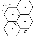
Fig. 2 shows the cellular communications network of being made up of first and second cellular systems that are subjected to the control of first (MSC-I) and second (MSC-II) mobile switching centre respectively;
Fig. 3 show and two directed microwave antennas between the cellular communication system of the common configuration of point-to-point microwave link;
Fig. 4 A shows the statement in the direct-cut operation zone of highly Utopian FM system;
Fig. 4 B shows the statement of the hard and soft handover area of highly Utopian cdma system;
Fig. 4 C shows highly Utopian Zone switched statement corresponding to the switching of CDMA to CDMA alien frequencies;
Fig. 5 shows one group of inside, conversion and second system base-station, is used to illustrate the function that remote unit is measured direct direct-cut operation table;
Fig. 6 shows the antenna direction figure of three fan-shaped base stations;
Fig. 7 illustrates CDMA to CDMA with the detection principle of switching frequently;
Fig. 8 illustrates the detection principle that CDMA to CDMA alien frequencies switches;
Fig. 9 illustrates in structure two base stations side by side that provide CDMA to CDMA alien frequencies to switch;
Figure 10 illustrates cdma system to utilizing different technology that the switching of the system of service is provided;
Figure 11 illustrates and utilizes single how fan-shaped base station to carry out the another kind of structure that CDMA to CDMA alien frequencies switches;
Figure 12 is the block diagram of the base station that comprises receive diversity of prior art;
Figure 13 has to send the block diagram of diversity with the border base station of generation path diversity;
Figure 14 has represented that use base station side by side is to carry out direct-cut operation;
Figure 15 represent to utilize the position close, the overlay area has obviously overlapping base station carry out direct-cut operation;
Figure 16 shows and puts to the use of putting " the quiet cone of silence (Cone of Silence) " in the crossing cdma system of microwave link; And
Figure 17 shows and puts to the use of putting " the quiet cone of silence " in the staggered cdma system of microwave link, and overlay area, the wherein quiet cone of silence and microwave overlay area are basic identical.
Embodiments of the present invention
Cell phone system, the little exchange of wireless special use (PBX) system, wireless local loop (WLL), PCS Personal Communications System (PCS) or other typical schematic diagram of analog wireless communication system are provided among Fig. 1.In another embodiment, the base station of Fig. 1 can be a satellite base station.System shown in Figure 1 can use various multiple access modulation techniques, so that communicate between a large amount of remote units and a plurality of base station.Known in this technology have a multiple multi-address communication system technology, and for example, time division multiple access (TDMA), frequency division multiple access (FDMA), code division multiple access (CDMA) also have for example amplitude compandored SSB amplitude modulation (AM) scheme.Yet, CDMA spread spectrum modulation technique and multi-address communication system these modulation techniques compare and have significant advantage.In U.S. Patent No. 4,901,307 (February 13 nineteen ninety bulletins, name is called " the spread spectrum multiple access communication system of utilizing satellite or land-based repeaters ", this patent has transferred assignee of the present invention, be incorporated herein, disclosed in as a reference) and in multi-address communication system, used CDMA technology.Though described the preferred embodiment that discloses here with reference to cdma system, many designs described herein can be used for the various communication technologys.
In above-mentioned U.S. Patent No. 4,901,307, disclosed a kind of multiple access technology, each has transceiver a large amount of mobile telephone system users, and transponder or ground base station utilize CDMA spread spectrum communication signal to communicate via satellite.When utilizing cdma communication, can repeat repeatedly to use same frequency spectrum, to transmit a plurality of different signals of communication.The result who uses CDMA can obtain the higher availability of frequency spectrum that Billy realizes with other multiple access technology, therefore, can increase the capacity of system user.
In typical cdma system, the pilot signal that each base station is unique.In preferred embodiment, pilot signal is to utilize public pseudo noise (PN) the extended code unmodulated direct sequence of emission continuously, spread spectrum signal by each base station.Each base station or base station section emission have the common pilot sequence of time migration with other base station.The code phase offset sign base station of the pilot signal that remote unit can receive from the base station according to it.Pilot signal also provides phase reference, carrying out coherent demodulation, and as the basis of switching signal strength measurement used when determining.
Refer again to Fig. 1, system controller and interchanger 10 (being also referred to as mobile switching centre (MSC)) generally comprise interface and treatment circuit, provide system's control to the base station.Controller 10 is also controlled the next call of public switch telephone network (PSTN) sends to the base station of suitable remote unit to suitable being used to route.Controller 10 is also controlled the calling of remote unit by the route of at least one base station to PSTN.Controller 10 can be controlled between the remote unit and call out by suitable base station.
General wireless communication system comprises some base stations with a plurality of sectors.Multi-sector base stations comprises a plurality of independently treatment circuits of antenna and some that independently transmit and receive.The present invention is applied to the base station of sectorization and the independently base station of each sector and single sectorization equally.The base station of sector of base station or single sectorization can be thought in term " base station ".
Controller 10 can be by being couple on the base station such as various means such as special telephone line, optical fiber link or microwave communications link.Fig. 1 shows typical base station 12,14,16 and typical remote unit 18.Remote unit 18 can be automobile telephone, hand-portable unit, PCS unit or wireless local loop unit, fixed position or any voice or data communications equipment that other is fit to.Arrow 20A-20B shows possible communication link between base station 12 and the remote unit 18.Arrow 22A-22B shows possible communication link between base station 14 and the remote unit 18.Equally, arrow 24A-24B shows possible communication link between base station 16 and the remote unit 18.
Base station location is configured to provide service to the remote unit of the overlay area that is positioned at them.When remote unit is idle, when promptly not conversing, near the pilot signal transmission of each base station remote unit constantly monitors.As shown in Figure 1, base station 12,14 and 16 respectively on communication link 20B, 22B and 24B to remote unit 18 emission pilot signals.In general, term " forward link " refers to the connection from the base station to the remote unit.In general, term " reverse link " refers to the connection from the remote unit to the base station.
In example shown in Figure 1, remote unit 18 can be thought and is in the overlay area of base station 16.Like this, the level of the pilot signal of the base station 16 that receives of this remote unit 18 will be than other pilot signal height of its supervision.When remote unit 18 begins to carry out Traffic Channel communication (being telephone relation), send the control message to base station 16.Base station 16 1 receives the call request message, just delivers a letter to controller 10, and the call transmission telephone number.Controller 10 is connected to the recipient who is intended to communicate by letter to this calling by PSTN then.
If PSTN sends calling, then controller 10 sends to one group of base station of registering its appearance near remote unit recently to call information.The base station is the Radio Paging message immediately.When the remote unit that is intended to communicate by letter receives its paging message, in response to nearest base station control message.Control message notifying controller 10, this specific base stations is just communicated by letter with remote unit.Controller begins this calling is routed to this remote unit surely by this base station.
If remote unit 18 has shifted out initial base station, for example the overlay area of base station 16 is then arrived another base station to transition of communications.Transition of communications is called switching to the processing of another base station.In preferred embodiment, the remote unit starting is also assisted hand-off process.
According to " the mobile radio station base station compatible standard of double mode broadband spread-spectrum cellular system ", TIA/EIA/IS-95 abbreviates IS-95 usually as, can be by the switching of mobile radio station self starting " remote unit assistance ".Remote unit is equipped with search receiver, except realizing other function, also is used for the emission of the pilot signal of scanning neighboring base station.Be better than given threshold value if find the pilot signal of one of neighbor base station (for example the base station 12), then remote unit is to message of current base station (base station 16) emission.This information sends controller 10 to by base station 16.After controller 10 receives this information, can start being connected between remote unit 18 and the base station 12.Controller 10 request base stations 12 Resources allocation are called out to this, and in this preferred embodiment, a Channel Elements is distributed in base station 12, handles this calling, and dividing the orientation controller 10 reports.Controller 10 is by base station 16 notice remote units 18, the signal of search base station 12, and the Traffic Channel parameter of informing base station 12 remote units.Remote unit 18 communicates by two base stations 12 and 16.During this was handled, remote unit continued sign and measures the signal strength signal intensity of the pilot signal that it receives.Like this, just realized the switching that remote unit is assisted.
Top processing also can be thought " soft " switching, and wherein remote unit communicates by more than one base station simultaneously.MSC during the soft handover can and the signal that receives of each base station of remote unit ongoing communication between make up or select.Each base station that MSC is communicating by letter to the signal forwarding of PSTN remote unit.Remote unit makes up each signal of base station that it receives, and produces accumulation result.
The review soft handover is handled, and can be clear that, MSC provides central authorities' control of processing.When if remote unit produces the situation of the overlay area that is positioned at the two or more base stations that are not same cellular system (promptly not being controlled by same MSC), remote unit is assisted to switch and is become more complicated.
Fig. 2 shows cellular communications network 30, and it comprises first and second cellular systems of being controlled by first and second moving exchanging center MSCs-I and MSC-II respectively.MSC-I and MSC-II are by being couple to first and second cellular systems respectively such as various means such as special telephone line, optical fiber link or microwave communications link.In Fig. 2, show five so respectively at the overlay area of first system C
1A-C
1EIn exemplary base station B
1A-B
1EWith five so respectively at the overlay area of second system C
2A-C
2EIn exemplary base station B
2A-B
2E
For ease of explanation, the overlay area C of Fig. 2
1A-C
1EAnd C
2A-C
2EHere the overlay area of the Fig. 3 that introduces subsequently illustrates circle or hexagon, and highly idealized.In the communication environment of reality, the size of base station coverage area and shape can change.Base station coverage area can be overlapping with coverage area boundaries, to limit and desirable circle or the different overlay area shape of hexagon.And the same as known in the art, the base station also can be divided by the sector and for example be divided into three sectors.
Because these overlay areas are near the border of first and second cellular systems, so can be overlay area C
1C-C
1EAnd C
2C-C
2EBe called border or conversion overlay area.Overlay area remaining in each system is called interior overlay area.
Quick check Fig. 2 is the not direct and base station B of MSC-II as can be seen
1A-B
1ECommunication, the not direct and base station B of MSC-I
2A-B
2ECommunication.As shown in Figure 2, MSC-I and MSC-II can with communicate with one another.For example the name EIA/TIA/IS-41 and the later release that are called " operating between cellular radio telecommunication system " defined the standard of communicating by letter between the exchange of the different operating scope shown in inter-system data link 34 among Fig. 2.For at base station B
1C-B
1EOne of with base station B
2C-B
2EOne of between carry out soft handover, must between MSC-I and MSC-II, transmit a large amount of call signal and power control information.Exchange may cause unsuitable time-delay to the prolongation of exchange connection and a large amount of call signal and power control signals, and may sacrifice resource undeservedly.Another difficult point that soft handover is provided is that the system of MSC-I control and the structure of the system that MSC-II controls can be to be very different.And the used Poewr control method of two systems also may sizable difference.Therefore, the present invention relates to provide a kind of mechanism that between two systems, carries out direct-cut operation, with complexity and the high cost of avoiding inter-system soft handoff.
The mechanism of direct-cut operation can be used for several situations.For example, the system of MSC-II control does not use CDMA to carry out signal communication, but can use FM, TDMA or other method.In this case, even in the system of MSC-I control, provide inter-system soft handoff, because soft handover just can carry out when all utilizing CDMA work in two systems only, so need direct-cut operation.Therefore, the present invention can be used for switching remote unit between two systems that use different air interfaces.Second system may need to improve, and with emission pilot signal or other CDMA beacon, handles to help the beginning direct-cut operation.At U.S. Patent Application Serial Number 08/413,306, publication number is that 5,594,718 name is called in " mobile unit is assisted the method for hard switching and the device of CDMA to another system " (nineteen ninety-five files an application) a kind of system that uses pilot beacon has been described in detail in detail.At common pending U.S. Patent Application sequence number 08/522,469, publication number is that 6,108,364 name is called in " common-frequency time division duplex repeater " (file an application August 31 nineteen ninety-five) another kind of system has been described in detail in detail.Above-mentioned two patent applications all transfer assignee of the present invention.At common pending U.S. Patent Application sequence number 08/322,817, publication number is 5,697,055 name is called in " method and apparatus that switches between different cellular communication systems " (file an application October 13 nineteen ninety-five) a kind of system that can use pilot beacon has been described in detail in detail, and this patent application also transfers assignee of the present invention.
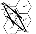
The another kind of situation that can use direct-cut operation is the situation that remote unit must change its operating frequency.For example, in the PSC frequency band, the point-to-point microwave link can be worked with cdma communication system.In Fig. 3, between oriented microwave antenna 130 and oriented microwave antenna 135, show a little to putting microwave link 140.Base station 40,100 and 110 may need to avoid using point-to-point microwave link 140 employed frequency bands, thereby avoids the interference between two systems.Because the high directionality of oriented microwave antenna 130 and oriented microwave antenna 135, point has very narrow zone to putting microwave link 140.As a result, other base station of system, for example can work in base station 115,120 and sector 50 and 70, and not noise spot to putting microwave link 140.Therefore, remote unit 125 can be operated in and put to the CDMA Channel of putting the identical frequency band of microwave link 140.If remote unit 125 is shifted to the communication on the frequency that is not supported in remote unit 125 works at present, then cannot finish from the base station 115 to 110 soft handover.The substitute is base station 115 can order remote unit 125 direct-cut operations to another frequency band of base station 110 supports.
The another kind of situation that can use direct-cut operation is the remote unit frequency that must change its work with the situation of distribution load more fifty-fifty.For example, in the PCS frequency band, the CDMA that communicates by letter with Traffic Channel is at a plurality of frequency bands (frequency band f for example
1With frequency band f
2) the transmission signal.If frequency band f
2The duty ratio frequency band f of efficient communication signal
1Weight, then frequency band f
2Some efficient communication signals be unloaded to frequency band f
1On be favourable.For distribution load effectively, by direct-cut operation between system, can be order with frequency band f
2The remote unit of work begins operating in frequency band f
1On.
Carry out the most reliable method of direct-cut operation and perhaps be making base station 115 in itself direct-cut operation on another frequency.Therefore, receiving from base station 115 on some points of sizable reliable signal at remote unit 125, base station 115 order remote units 125 are operated on the different frequency of supporting base station 115.The signal of receiving remote unit transmission is launched and is attempted in base station 115 beginnings on new frequency.On the other hand, direct-cut operation can carry out between the second frequency of the first frequency of base station 115 and base station 110.Neither one needs intersystem communications in two types the direct-cut operation.
Refer again to Fig. 2, the call of the control PSTN of first mobile switching centre (MSC-I) is to suitable base station B
1A-B
1ERoute, with to the transmission of the remote unit of appointment.MCI-I also controls the calling of a remote unit in the overlay area by the route of at least one base station to PSTN.MSC-II with control base station B
2A-B
2EThe identical mode of work work, determine PSTN and base station B
2A-B
2EBetween route.Can utilize such as IS-41 industrial standard or follow-up second edition standard, on inter-system data link 34, between MSC-I and MSC-II, transmit control message etc.
When remote unit is arranged in the overlay area of inner base station, remote unit is programmed, monitor the pilot signal transmission of one group of neighbor base station.Suppose that remote unit is positioned at overlay area C
1DSituation, but its forward overlay area C
2DClose.In this example, remote unit can begin to receive base station B
2DThe available signal level, then this signal is reported to base station B
1DAny other base station of communicating by letter with current remote unit.Remote unit is receiving the time of available signal level and can determine by the one or more measurable parameter (for example signal strength signal intensity, signal to noise ratio, frame error rate, frame erasure rate, bit error rate and/or relative time delay) of measuring received signal.In preferred embodiment, measurement is to carry out according to the pilot signal strength that remote unit receives.Detect available received signal level at remote unit, and utilize signal strength signal intensity or quality message to base station B
1DAfter the report, following processing is from base station B
1DTo base station B
2DSame frequency remote unit assist direct-cut operation:
(i) base station B
1DBase station B
2DRemote unit report signal level relaying give MSC-I, MSC-I notices base station B
2DControlled by MSC-II;
(ii) MSC-I is on inter-system data link 34, from MSC-II at base station B
2DTrunk equipment between the system between last request channel resource and two systems;
(iii) MSC-II is in response to request, by inter-system data link 34 information offered MSC-I, and the MSC-I sign will be set up the channel and the out of Memory of communication.In addition, controller is at base station B
2DThe interior allocated channel and the main line resource of communicating by letter that keep with remote unit;
(iv) MSC-I is by base station B
1DProvide new channel information to remote unit, and the assigning remote unit begins and base station B
2DThe time that communicates;
(v) by direct-cut operation at remote unit and base station B
2DBetween at the appointed time go up to set up communication; And
(vi) MSC-II confirms that to MSC-I remote unit successfully is transformed into this system.
A difficult point of this scheme is that MSC-I does not know base station B
2DWhether receive the communication of signal support this moment of enough level from remote unit.MSC-I order remote unit and base station B
2DSet up communication.Equally, base station B
2DStill may not receive available signal level from remote unit.As a result, when treatment conversion arrives the control of MSC-II, can lose this calling and connect.Lose if call out to connect, then MSC-II sends error message rather than affirmation to MSC-I.
Another difficult point that direct-cut operation is provided is the attribute of the coverage area boundaries of cdma system.In the FM system, for example in AMPS, the covering area overlapping scope is quite wide.The covering area overlapping scope is to support the zone of communicating by letter one of in the remote unit base station different with two separately between the base station.In the FM system, this covering area overlapping scope must be extensively wide, and this is could successfully carry out direct-cut operation because have only when remote unit is arranged in the covering area overlapping scope.For example, Fig. 4 A is the Utopian statement of FM system height.Base station 150 can provide forward to communicate by letter with reverse link FM to remote unit 155 with base station 165.(forward link refers to the connection of base station to remote unit.Reverse link refers to the connection from the remote unit to the base station.) in zone 160, the level of the signal strength signal intensity of two base stations 150 and base station 165 is enough to support to communicate with remote unit 155.Note that the attribute owing to FM, can not communicate by letter with remote unit 155 with 165 simultaneously in base station 150.When taking place from the base station 150 in zone 160 to the base station during 165 direct-cut operation, communicating by letter between base station 165 and the remote unit 155 used the frequency of use between a new frequency rather than base station 150 and the remote unit 155.Launch on the frequency that never use in base station 150 base station 165, thus base station 165 on paper can interference base station 150 with arbitrary remote unit between the communication carried out of the usefulness frequency of communicating by letter.Border 182 pointed out can not be from the base station 165 positions to remote unit 155 communications.Equally, border 188 pointed out can not be from the base station 150 positions to remote unit 155 communications.Obviously Fig. 4 A and Fig. 4 B and 4C do not come picture in proportion, in fact, compare with total overlay area of each base station, and the covering area overlapping scope is rather narrow.
Utilize the CDMA soft handover, only just can support fully that with a base station in two base stations the covering area overlapping scope of communicating by letter just there is no need to have existed.In the scope that soft handover takes place,, then be enough to keep reliably communication if set up communication simultaneously with two or more base stations.In cdma system, usually effectively the base station is operated on the identical frequency with neighbor base station.Therefore, when remote unit near during the overlay area of neighbor base station, effectively the signal of base station level descends, the interference level of neighbor base station increases.Because the cause that the interference of neighbor base station increases, if do not set up soft handover, effective being connected and may being on the hazard between base station and the remote unit then.If with respect to effective signal of base station decline, and do not decline, then especially can threaten connection with respect to the signal of neighbor base station.
Fig. 4 B is the idealized statement of cdma system.Cdma base station 200 and cdma base station 205 can provide forward and reverse link cdma communication to remote unit 155.In the darkest zone 170, though only with base station 200 or base station 205 in a base station set up and communicated by letter, the level of two base stations 200 and the signal strength signal intensity of base station 205 is enough to support to communicate by letter with remote unit 155.184 places on the border, only the communication by base station 205 is insecure.Equally, 186 places on the border, only the communication by base station 200 also is insecure.
Note that Fig. 4 A and 4B are by each other with reference to coming picture.The value of reference number that is used to specify border 180,182,184,186,188 and 190 is along with from the base station 150 and the increase of the distance of base station 200 and increasing.Therefore, the soft handover area between the border 180 and 190 is the wideest scope.FM covering overlapping area between the border 182 and 188 is positioned at the CDMA soft handoff range.CDMA ' direct-cut operation ' zone is the narrowest zone between border 184 and 186.
Note that if base station 200 belongs to first system, and base station 205 belongs to second system, then may communicate by letter with remote unit 155 with base station 205 simultaneously in base station 200.Therefore, if communication need be from the base station 200 is transformed into base station 205, then need to carry out from the base station 200 to the base station 205 direct-cut operation.Note that remote unit must be in the CDMA direct-cut operation zone between the border 184 and 186 in the zone 170, so that direct-cut operation has higher success rate.Its difficult point is that in fact, direct-cut operation zone 170 can be extremely narrow, and remote unit 155 moves into and shift out direct-cut operation 170 time spents of zone can be very short.In addition, be difficult to also determine that remote unit 155 is whether in direct-cut operation zone 170.Be in the direct-cut operation zone 170 in case determine remote unit 155, then must make decision and whether should carry out direct-cut operation, switch to which base station, and when switch.The present invention is exactly at these problems.
A first aspect of the present invention is must and to complete successfully the scope of direct-cut operation and the direct-cut operation of trial possibly in a kind of definite overlay area to answer direct-cut operation to arrive which base station.Hexagon tiling structure shown in Figure 3 is highly Utopian.When system's practical development, there is various shape the overlay area that obtains.Fig. 5 shows the more real statement of one group of base station.Base station T
1-T
3And base station I
1-I
3It is the part of first communication system that is subjected to controller 212 control of system 1.Base station I
1-I
3Be inner base station, it is only approaching with other base station of same system.Base station T
1-T
3Be conversion or border base station, its overlay area is in abutting connection with the overlay area that belongs to the base station of different operating system.Base station S
1-S
3It is a part that is subjected to second system of system's 2 controllers, 214 controls.Outmost thick concentric circles comprises base station S
3, base station I
1-I
3With base station T
2-T
3, expression Utopian overlay area, base station can be set up with corresponding base station in this zone and communicate by letter.Outmost bold curve has surrounded base station S
1-S
2With base station T
1, the more real overlay area of expression corresponding base station.For example curve 228 is represented base station S
1The overlay area.The shape of overlay area is subjected to the influence of place, base station landforms to a great extent, for example height and the trees in the overlay area, massif and other barrier of high constructure in height, quantity, reflectivity and the overlay area of antenna installation.For ease of drawing, the actual coverage area territory of each base station is not shown.
In the system of reality, some base stations can be changed into three sectors by the sector.Fig. 6 shows the antenna pattern of three sector base stations.The base station of three sectors is not shown, so that drawing in Fig. 5.Principle of the present invention can directly apply to the base station of sectorization.
In Fig. 6, the thinnest line has been represented overlay area 300A.Middle thick line is represented overlay area 300B.The thickest line is represented overlay area 300C.The shape of three overlay areas shown in Figure 6 is shapes that the oriented dipole antenna of standard produces.The edge of overlay area can think that remote unit receives minimum signal level to support communicating residing position by this sector.When remote unit moved into the sector, as remote unit sensed, the signal strength signal intensity that receives from the base station increased.Remote unit on this point 302 can communicate by sector 300A.Remote unit can communicate by sector 300A and sector 300B on the point 303.Remote unit on the point 304 communicates by sector 300B.When remote unit moves through the edge of sector, may deterioration by the communication of this sector.The remote unit that carries out work with soft handoff mode between the base station of Fig. 6 and unshowned neighbor base station may be positioned on the edge of one of sector.
Three fan zoning base stations of betterization have been represented in the base station 60 of Fig. 3.Base station 60 has three sectors, and the base station coverage area that each sector covers is greater than 120 degree.The overlay area that sector 50 has is with solid line 55 indications, and with the covering area overlapping of sector 70, indicate with thick dashed line 75 overlay area of sector 70.Sector 50 is also overlapping with sector 80, and indicate with fine line 85 overlay area of sector 80.For example, be positioned at the overlay area of sector 50 and sector 70 with the position 90 of X indication.
Usually base station sectionization to reduce total interference power to the remote unit that is positioned at base station coverage area, increase the quantity of the remote unit that can communicate by this base station simultaneously.For example desired signal is not launched to the remote unit that is positioned on the position 90 in sector 80, and therefore, the remote unit on position 90 can not cause obvious interference to the remote unit that is positioned at sector 80 with communicating by letter of base station 60.
For the remote unit that is positioned on the position 90, total interference is from sector 50 and 70 and base station 115 and 120.The remote unit that is positioned at position 90 can be in soft handover with sector 50 and 70.The remote unit that is positioned on the position 90 can be in soft handover simultaneously with one of base station 115 and 120 or both.
Remote unit assistance soft handover comes work according to the pilot signal strength of several groups of base stations that remote unit records.Effectively group is a group of base stations of having set up efficient communication.Adjacent groups is the one group of base station that is centered around around effective base station, comprises the base station that has the high signal intensity level that is enough to set up communication probably.Candidate set is the group of base stations that the signal level of pilot signal strength is enough to set up communication.
When beginning to set up communication, remote unit is by first base station communication, and effectively group only comprises first base station.Remote unit monitors is the pilot signal strength of the base station of group, candidate set and adjacent groups effectively.When the pilot signal of a base station in the adjacent groups surpasses predetermined level, this base station is joined in the candidate set, and from the adjacent groups of this remote unit, remove this base station.Remote unit transmits a message to first base station, identifies a new base station.System controller determines whether to set up between new base station and remote unit and communicates by letter.If system controller decision is set up, then system controller has the message and the order of the identification information relevant with remote unit to new base station transmits one, to communicate by letter with its foundation.Also pass through first base station to the remote unit message transmission.This message identification marking one is new effective group, comprise first and new base station.Remote unit is searched for the information signal of new base station, sets up with new base station and communicates by letter, and does not interrupt the communication by first base station.This processing can be proceeded with other base station.
When remote unit passed through a plurality of base station communication, its persistent surveillance is the signal of base station intensity of group, candidate set and adjacent groups effectively.Be lower than predetermined threshold and continue a scheduled time if drop to corresponding to the effective signal of base station intensity of group, then remote unit produces and sends a message, reports this incident.The base station that system controller is being communicated by letter with it by at least one this remote unit receives this message.System controller can determine to interrupt with pilot signal strength a little less than the communicating by letter of base station.
System controller interrupts communication by a base station once decision and produces the new effective group of base stations of a message identification one.New effective group of base stations does not comprise the base station of interrupt communication.The base station of having set up communication sends a message to remote unit.System controller also transmits information to this base station, to interrupt and the communicating by letter of remote unit.So, remote unit only with new effectively group in the base station of sign communicate.
When remote unit was in soft handover, system controller received decoded data packets from each base station of effective group membership.According to this group signal, system controller must produce individual signals and be transferred to PSTN.In each base station, before being decoded, they can make up the signal that receives from same remote unit, therefore made full use of the advantage that many signals receive.The decoded result of each base station is offered system controller.The signal in case decoded, just can not be easily and advantageously with other signal ' combination '.In preferred embodiment, system controller must be selected between a plurality of decoded signals corresponding to the man-to-man base station of having set up communication.From one group of signal of base station, select a best decoded signal, abandon other signal simply.
Except soft handover, system also can use " softer " to switch.Than soft handover generally with same sector of base station between switch relevant.Because the connection of same sector of base station is very tight, thus by combination not decoding data rather than select decoded data just can carry out switching between the same sector of base station.Whether the present invention is applied to will use than soft handover in one of two systems equally.Than the processing of soft handover at U.S. Patent application No.08/405,611, publication number is 5,625,876 name is called " method and apparatus that switches " (application on March 13 nineteen ninety-five between same sector of base station, be the U.S. Patent application No.08/144 that applied on October 10th, 1 now, the continuation application that 903 publication numbers are, this two application has all transferred assignee of the present invention) in description is arranged.
In preferred embodiment, select to handle by the system controller in selector row's subsystem (SBS).SBS is made up of a group selector.Each selector is handled the efficient communication of a remote unit.When calling out connection termination, can distribute to another efficient remote unit to this selector.Selector provides the controlled function of form of ownership for remote unit and base station.Selector sends and receives message from the base station.An example of this message is that each round trip between base station and remote unit is delayed time when having changed a threshold quantity message that sends from the base station.Selector also can order the base station to send message to remote unit.An example of this message is to send to the message that its order remote unit of base station commands provides pilot frequency intensity measuring message (PSMM).More fully explain the purposes of this two signal below.In the most common embodiment, do not need selector to control hand-off process, any type of communication control unit can realize that these functions replace the selector in the preferred embodiment.
Set up when communicating by letter with the base station when remote unit, the round trip time-delay (RTD) related with remote unit can be measured in the base station.The base station is according to the time of universal time calibration to the remote unit transmission.The base station transmits to remote unit on wireless air-link.Some times of signal demand of emission could arrive remote unit from the base station.Remote unit utilizes signal calibration that it receives from the base station, and it sends back the transmission of base station.By compared with the base station time calibration of the signal that receives from remote unit in the base station to the calibration of the signal of remote unit, line delay can be determined to come and go in the base station.Round trip time-delay can be used for estimating the distance between base station and the remote unit.According to preferred embodiment, when the variable quantity of round trip time-delay surpassed predetermined value, this round trip time-delay was just reported to selector in the base station.
One aspect of the present invention utilizes the remote unit and the effective position of the round trip time-delay sign remote unit between the base station of group and candidate set a member.Obtain remote unit and be that round trip time-delay between the base station of candidate set a member is more complicated slightly than the round trip time-delay of determining effective group of a member.The signal of remote unit because do not decode in the base station of candidate set a member is so candidate base station can not directly be measured the round trip time-delay.
The message (pilot information that comprises member in candidate set and the effective group) that remote unit sends to the base station is called as pilot frequency intensity measuring message (PSMM).Remote unit is in response to the request of base station or because the signal of base station intensity of adjacent groups has surpassed threshold value, perhaps the signal strength signal intensity of candidate set has surpassed intensity one scheduled volume of one of effective group of base station, perhaps owing to switching and abandoning the timer time and transmit PSMM.
Four parameters are being controlled soft handover and are being handled.First is pilot detection threshold value T_ADD, has stipulated that the pilot signal strength of adjacent groups member's base station must surpass to be categorized into candidate set member's level.Pilot tone whereabouts threshold value T_DROP has stipulated effectively or the pilot signal strength of candidate set member's base station must drop to below certain level with the triggering timing device.Stipulate by T_TDROP during the timer that triggers.After having passed through the T_TDROP official hour, if the intensity of pilot signal still is lower than the T_DROP level, then remote unit begins to remove relevant base station from its current affiliated group.Effectively group must surpass effective group membership's pilot signal strength to trigger the amount of PSMM to the pilot signal strength that the compare threshold T_COMP of candidate set is provided with the member of candidate set.These four parameters all are stored in the remote unit.The message reprogrammed that each parameter in these four parameters can utilize the base station to send arrives new value.
PSMM has comprised two information among the present invention.PSMM comprises the record of each pilot signal, corresponding to a member of effective group or candidate set.At first, PSMM comprises the measurement of signal strength signal intensity.Secondly, PSMM comprises the measurement of pilot signal phase.Remote unit is measured the pilot signal phase of each pilot signal in the candidate set.Among the available multi-path component that arrives the earliest in the candidate pilot and the effective group membership the earliest the available multi-path component of arrival compare, and in remote unit the measurement pilot signals phase place.Pilot signal phase can measured in the PN chip relatively.The pilot signal that base station in effective group of arriving signal the earliest is provided is as reference pilot signal.
System controller can utilize following formula that pilot signal phase is translated into round trip time-delay estimated value:
RTD
Canl=RTD
Ref+ 2* (PlilotPhase
Canl-ChannelOffset
Canl* formula 1 PilotInc)
Wherein:
RTD
CanlEstimated value is calculated in=round trip the time-delay that has the base station of inlet in candidate set;
RTD
RefThe round trip time-delay of=reference pilot signal report;
PilotPhase
CanlThe phase place of the universal time of reporting among the PSMM the in=PN chip unit that provides with respect to remote unit;
ChannelOffset
CanlThe channels offset of=candidate base station is a no unit number; And
PilotInc=is system's wide pilot frequency sequence skew index increment of unit with the PN chip of each channel.
The round trip time-delay RTD of reference pilot signal report
RefOffer selector by corresponding base station.Benchmark is equipped with the basis of the round trip time-delay of pilot signal as round trip time-delay between the base station of estimating remote unit and candidate set member.Remember that in preferred embodiment each base station sends the identical pilot frequency sequence with time migration, so that remote unit can be according to the symbol phases skew sign base station of pilot signal.Pilot frequency sequence skew index increment PilotInc is the symbol phases skew increment of skew base station pilot signals.The channels offset of candidate base station, ChannelOffset
CanlAppointment is distributed to candidate base station to which symbol phases.The relative phase of candidate base station, PilotPhase
CanlIt is the symbol phases skew of the candidate base station that remote unit records when being unit and reference pilot signal comparison with the PN chip.PilotPhase
CanlIn PSMM, report to the base station.ChannelOffset for selecting device
CanlWith PilotInc be known.
If there is not transmission delay in system, then the phase place of candidate base station will be pilot frequency deviation ChannelOffset
CanlLong-pending with the wide pilot frequency sequence skew index increment PilotInc of system.Owing in system, there is transmission delay, thus remote unit sense the time-delay of reference pilot signal and candidate base station pilot signal be different with change.From PN the skew (=PilotPhase that senses
Canl) in deduct and comprise PN skew (=ChannelOffse
CanlLong-pending with PilotInc) system, the relativity shift between the pilot signal of output reference pilot signal and candidate base station.If difference is for negative, then the RTD between Reference BTS and the remote unit is greater than the RTD between candidate base station and the remote unit.The difference that remote unit senses has only reflected the time-delay of forward link.The relative time delay of forward link is doubled to think omnidistance round trip time-delay.
As an example, the wide pilot frequency sequence skew of supposing the system index increment is the 64PN chip, and the basis of following information as the round trip Time delay measurement.
PilotPhase
Ref=0 RTD=137 (base station Id=12)
PilotPhase 14=948 RTD=244 (base station Id=14, relativity shift 52PN)
PilotPhase 16=1009 (base station Id=16, relativity shift-15PN)
Because in preferred embodiment, each base station or base station section send has the same pilot sequence of time migration, and it is identical with the used channel PN skew of base station pilot signal transmitted that identification of base stations can be thought.Suppose that again base station 12 and base station 14 (can think relevant with the base station of Fig. 1) are the members of effectively basic group, the RTD that carries out when base station 12 and 14 is measured measures respectively with 137 and 244 PN chip reports.
Note that the right side of pilot phase and the round trip delay data of base station 14 are the relativity shifts that calculate.The pilot phase of the base station 14 that records is 948 PN chips.The base station IDs (14) that equals the constant offset of base station 14 multiply by pilot frequency sequence skew increment (64), and it equals 896 PN chips.The difference of the pilot phase of the base station that records and pilot phase skew equals the relativity shift between base station and the remote unit, be in this example 52 PN chips (=948-896).Needn't delay time with the round trip between these numerical calculation base stations 14 and the remote unit, this is because base station 14 is effectively to organize 14 member, directly carries out the measurement of round trip time-delay.
Yet because base station 16 is members of candidate set, the round trip Time delay measurement is not directly carried out in base station 16, so must determine the round trip time-delay with above-mentioned formula 1.For base station 16, parameter is:
RTD
Ref=137PN chip;
PilotPhase
Canl=1009PN chip;
ChannelOffset
canl=16;
PilotInc=64PN chip/channel
The direct substitution formula 1 of these numerals, the round trip time-delay between output remote unit and the base station 16,107 PN chips.As mentioned above, in order to find the absolute drift of candidate base station, from PilotPhase
CanlIn deduct ChannelOffset
CanlLong-pending with PilotInc, in this example, output valve is-the 15PN chip.More noticeable is that round trip time-delay between base station 16 and the remote unit is delayed time less than the round trip between the base station 12.
The first method of identification remote unit location is relevant with direct direct-cut operation (MDHO) state that utilizes particular remote unit to measure.So that make the minimum that influences of processing, only when the arbitrary member who effectively organizes is marked into the conversion base station system enter the MDHO state.System just entered the MDHO state when in another embodiment, only all members in effectively organizing were for the conversion base station.In another the 3rd embodiment, in only ought effectively organizing single base station is arranged, and this base station is that system just enters the MDHO state when changing the base station.In the 4th embodiment, enough processing resources are arranged, so that MDHO is always effective.When the MDHO state, selector monitors effective group membership's round trip time-delay, and the time-delay of calculated candidate group membership's round trip.After the condition changing that triggers the MDHO state, can withdraw from the MDHO state.
The MDHO state is based on and utilizes the MDHO table.In the MDHO table, the part of every line display covering area overlapping scope.As defined above, the covering area overlapping scope is to make the supported zone of communicating by letter separately between remote unit and one of two different base stations.Every row comprises the tabulation of paired base station identifying signal and round trip reference time delay.The round trip reference time delay is by minimum and maximum round trip stroke time-delay defined.
In order to utilize the MDHO table, discern a class range and the corresponding suitable action of each scope with network planning instrument or empirical data.On the other hand, rule-based or expert system can be used for producing the MDHO table.As mentioned above, Fig. 5 shows one group of inner base station, conversion base station and second system base-station, is used to illustrate the function that remote unit is measured direct direct-cut operation table.Hacures indication round trip Time delay measurement threshold value around the base station.For example, be trapped among base station S
2The such position of hacures 222 expressions on every side, base station S in this position
2Show the round trip time-delay of 200 PN chips to the directapath that is positioned at the remote unit on these hacures 222.Be centered around base station S
2The such position of hacures 220 expression, base station S in this position
2Show the round trip time-delay of 220 PN chips to the directapath that is positioned at the remote unit on these hacures 222.Therefore, the round trip time-delay that shows of any remote unit between hacures 220 and hacures 222 is between 200 and 220 PN chips.
Equally, be centered around base station T
1The such position of hacures 226 expressions on every side, in this position, base station T
1The round trip time-delay that shows to the directapath that is positioned at the remote unit on the hacures 226 is 160 PN chips.Be centered around base station T
1The such position of hacures 224 expressions on every side, in this position, base station T
1The round trip time-delay that shows to the directapath that is positioned at the remote unit on the hacures 2246 is 180 PN chips.Therefore, the round trip time-delay that shows of any remote unit between hacures 224 and hacures 226 will be between 160 and 180 PN chips.
And, be centered around base station S
1The such position of hacures 232 expressions on every side, on this position, base station S
1The round trip time-delay that shows to the directapath that is positioned at the remote unit on the hacures 232 is 170 PN chips.Be centered around base station S
1The such position of hacures 230 expressions on every side, on this position, base station S
1The round trip time-delay that shows to the directapath that is positioned at the remote unit on the hacures 230 is 180 PN chips.Therefore, any remote unit between hacures 230 and hacures 232 is with respect to base station S
1The round trip time-delay that shows will be between 170 and 180 PN chips.
As mentioned above, do not adopt the multi-path signal of the directapath between remote unit and the base station to produce by the reflection factor in the environment.If signal does not adopt directapath, then the round trip time-delay will increase.The signal of Dao Daing is the signal that adopts shortest path between remote unit and the base station the earliest.The present invention measures the signal that arrives the earliest to estimate the round trip time-delay.
Note that concrete scope can be delayed time by the round trip between each base station discerns.For example, coverage 240 and 242 can be discerned like this, i.e. remote unit and base station T
1Between round trip time-delay between 160 and 180 PN chips, remote unit and base station S
2Between round trip time-delay between 200 and 220 PN chips.Overlay area 242 is also limited by such factor, and no matter what value is the round trip retardation of pilot signal be, can sense from base station S fully
1Pilot signal.Suppose the scope that is positioned at 240 and with base station T
1The suitable action of the remote unit of communicating by letter is to proceed to cdma base station S
2Same frequency direct-cut operation.Suppose also that in scope 242 total interference is very high, so that can only carry out another to base station S
1The direct-cut operation of the AMPS system that supports.
Table I shows the part of typical MDHO table.Which covering area overlapping scope first row have indicated corresponding to the row in the MDHO table.For example, overlay area 242 is corresponding to the coverage N on the Table I, and overlay area 240 is corresponding to the overlay area N+1 on the Table I.Note that remote unit that is positioned at overlay area 242 and the parameter matching that offers overlay area 240.In an illustrated embodiment, the MDHO table is by the numerical order traversal, and first scope of selection and given parameter matching is performed such: is given parameter group and scope N+1 unique channel relatively that scope N has been excluded as a possible position.Secondary series comprises first base station IDs.The 3rd row comprise the scope corresponding to the round trip time-delay of the overlay area of row appointment.The the 4th and the 5th row show second base station IDs and the round trip time-delay is right, and the 6th is identical with the 7th row.Can increase more row if desired, specific base ID and round trip time-delay are right.
In preferred embodiment, the MDHO table is stored in selector row's subsystem controller (SBSC).SBSC has stored the pilot data storehouse, and it provides neighbor base station table and pilot frequency deviation and other standard operation needed these class data.In preferred embodiment, when receiving PSMM at every turn, and when the RTD of arbitrary effective base station measurement has changed a tangible value, selector request SBSC visit MDHO table.
| Coverage | BS Id [1] | RTD scope [1] | BS Id [2] | RTD scope [2] | BS Id [3] | RTD scope [3] | Action | System identifier | Target BS Id | ||
| · · · | |||||||||||
| | T1 | 160,180 | | 200,220 | S1 | 0,1000 | HO to AMPS | SYs2 | S1 | ||
| N+1 | | 160,180 | | 200,220 | HO to CDMA | SYs2 | S1 | ||||
| N+2 | | 160,180 | | 200,220 | HO to CDMA | SYs2 | S1 | ||||
| N+3 | | 160,200 | T3 | 0,1000 | HO to Dif Freq CDMA | SYs1 | T2 | ||||
| N+4 | | 200,240 | | 190,210 | | 200,240 | HO to AMPS | SYs1 | T2 | ||
| · · · |
Table I
The action description of row mark the action that should take place during corresponding to one of overlay area when the position of remote unit.Several actions that typically can adopt are arranged, for example:
Intersystem base station CDMA to AMP direct-cut operation;
CDMA to AMP direct-cut operation in base station in the system;
Intersystem base station CDMA to CDMA direct-cut operation;
CDMA is to different CDMA direct-cut operations frequently between system;
CDMA is extremely with frequency CDMA direct-cut operation between system.
More if desired round trip delayed data is discerned the position of remote unit, then revises T_ADD and T_DROP threshold value when remote unit is in the MDHO state.Reduce T_DROP and T_ADD threshold value, the member that lower pilot signal strength just can make corresponding base station become candidate set and effectively organize, and before being abandoned, lower pilot signal strength still can be in candidate set and is effectively kept the longer time in the group.Be listed in candidate set and effectively the quantity of the base station in the group increase, increased the data point that can be used for to the round trip time-delay of remote unit location.The system-wide that reduces T_ADD and T_DROP is passable, uses the system resource of two base stations to produce adverse influence in switching to each remote unit.Wish to make the quantity minimum of the remote unit that is in the switching, preserving the resource of each base station, and make the capacity maximum.Therefore, in preferred embodiment, only in the conversion base station, reduce the value of T_ADD and T_DROP.And, can increase the time span of T_TDROP appointment, drop to and be lower than the time that is retained in after the T_DROP in effective group to increase the base station.
In preferred embodiment, if second system not from border base station with the used frequency emission CDMA pilot signal of first system, second system of then revising is with emission pilot signal or other CDMA beacon, to assist starting U.S. Patent Application Serial Number 08/413 as mentioned above, 306, publication number is 5,594,718 and U.S. Patent Application Serial Number 08/522,469, publication number is the direct-cut operation of describing in 6,108,364.In another embodiment, though system from border base station emission CDMA pilot signal, the second intrasystem border base station does not produce pilot signal, and corresponding to base station S
1-S
3The base station IDs row of MDHO table in do not have list item.Also can in inner base station, use the pilot beacon unit, with the zone that helps identification point-to-point microwave link to work.
Under some situations, also can like this, only be left to determine the position of remote unit not the means of candidate base station as the position of identification remote unit with effective base station information.For example, with the exquisite network planning, it can only utilize effective group member's round trip time-delay to discern the covering area overlapping scope effectively.
As mentioned above, figure 5 illustrates the not base station of sectorization, to simplify drawing.In fact, carry out sectorization, remote unit can positioning range be diminished, help localization process.Note the geometry of base station 60 for example shown in Figure 3.Before considering the round trip time-delay, the overlay area of base station 60 is divided into 6 different scopes: the zone that is covered by sector 50 only, by the zone of sector 50 and sector 70 coverings, the zone that is covered by sector 70 only, by the zone of sector 70 and sector 80 coverings, the zone that is covered by sector 80 only, and the zone that is covered by sector 80 and sector 50.If network design is used for these three fan zoning base stations are carried out orientation along the border between two systems, then can be without the pilot beacon in system's 2 border base stations, and needn't use candidate base station determining to the round trip time-delay.
Begin intrasystem each base station is calibrated, make with the decibel to be the uncharge receiver path noise that records of unit and to be that the desired pilot power sum that unit records equals a certain constant with the decibel.This calibration constants is consistent in whole base station system.When system becomes (remote unit begins and base station communication) when load is arranged, link handoff boundary to reverse link handoff boundary is effectively near this base station.Therefore, for imitate with forward link on identical effect, when load increases, reduce pilot power, compensating network makes between the pilot power of power of reverse link that receives on the base station and base station and keeps constant relationship.Balance forward link handoff boundary is called base station area flexible (breathing) to the processing of link handoff boundary to reverse link handoff boundary, at U.S. Patent number 5,548,812, name is called in " balance forward link handoff boundary is to the method and apparatus of link handoff boundary to reverse link handoff boundary in cellular communication system " (this patent was announced on August 20th, 1996, and transferred assignee of the present invention) description.
The flexible processing in zone is disadvantageous operation under the MDHO state.Refer again to Fig. 4 B, reduced if base station 200 emitted power are compared with base station 205 emitted power, then move near to the base station 200 on the covering area overlapping border, and away from base station 205.Signal level can not influence the round trip time-delay between arbitrary locational remote unit and the base station.Therefore, when actual boundary may change, when suitably switching, the MDHO table can continue to be used for discerning identical position.
The flexible method of several processing regions is arranged.A kind of method is to make the qualification covering area overlapping scope that is stored in the MDHO table enough little, and is irrelevant with the flexible state in current zone so that this covering area overlapping scope is remained valid.
Handle the flexible second method of base station area and be forbid or the zone of restricted boundary base station flexible.The gap mapping device is worked on forward link, forces the performance of forward link to imitate the natural reaction of reverse link to the load of machinery systems.Therefore, the cancellation zone is flexible can not reduce the danger that the border changes with the load on the reverse link, and therefore, even system does not use the zone flexible, load also can be left a factor.
Handling the third flexible method of base station area is to pass through networking rule.If the border base station of second base station not with the used frequency emission traffic channel signal of the border base station of first system (being efficient remote unit special signal), then make the zone flexible influence minimum.If border base station from pilot beacon unit emission pilot signal, is can not produce traffic channel signal owing to use the pilot beacon unit, thus also make the zone flexible influence minimum.The power of pilot beacon unit output keeps constant in time.
Handling the 4th kind of flexible method of base station area is to utilize rule-based system.If it is flexible that border base station is the zone, then each base station is to the flexible parameter in system controller sending zone.System controller upgrades the MDHO table according to the flexible currency in zone.Usually system controller will increase the round trip delay value in the MDHO table, with the flexible influence of reflecting regional.
The flexible influence in zone may not be a problem under most of situations.Because these borderline regions normally produce because of technology and business problem, so the network planning generally strives making the border to place in the low service area between two systems, the flexible influence in less professional corresponding zone is with less.
In some cases, can wish to avoid storage and visit MDHO table.In this case, can influence switching with some other method.For example, in another embodiment, trigger switching with two kinds of means.First method is called the detection rule.Some base station (or base station section) is appointed as Reference BTS R.If remote unit is positioned at the overlay area of Reference BTS, and report detects triggering pilot signal P
B, then selector triggers and uses data set (R, P
B) switching of the target BS determined.General pilot beacon unit always is not to use this detection rule.
Second method is called biography rule (hand-down rule) down.Some base station is marked into border base station.If remote unit only comprises a base station for effective group, and this base station is border base station, and the time-delay of reference pilot signal round trip surpasses threshold value, and then selector just triggers and switches.On the other hand, if effective group of base station that only comprises border base station of remote unit, and the time-delay of reference pilot signal round trip surpasses threshold value, then just triggering switching of selector.Usually, this threshold value changes between the base station, and is irrelevant with effective group remaining part.Underdrive is done to be determined by current reference pilot.Following biography rule can be first rule of measuring in one group of rule directly switching.Notice that the area of coverage that is designated as the base station of border base station needn't be adjacent with the overlay area of the base station of another system.Under pass rule and can be used between system switching and intra-system handover.
Detecting regular and pass rule down all may be relevant with the physical characteristic of system.Use these two rules to increase burden to network design, for example to base station location, to carrying out orientation and to the actual location of antenna in the sector in the multi-sector base stations.
If starting calling in border base station is attempted in remote unit or base station, then remote unit or base station exchange start message on access channel.In preferred embodiment, the overhead channel manager resides in the base station, the control access channel.The inspection of overhead channel manager is estimated from the round trip time-delay that start message calculates.If surpass threshold value when advancing, then mobile switching centre is just notified in the overhead channel management, can order this base station to send the service redirection message to remote unit.The service redirection message can be assigned to the remote unit that can carry out AMPS in the AMPS system, perhaps in another CDMA frequency or the system.Redirection message is also relevant with the COS that remote unit requires.If require data to connect rather than the voice connection, then the AMPS system may not support this connection.Therefore, the action of taking generally must be relevant with the ability and the state of remote unit.Usually, each remote unit in the system has classification specifies, and specifies its ability.The current state of remote unit can be inquired in the base station, and makes decision according to the information of returning.
Fig. 7 is illustrated in CDMA to CDMA and uses this detection in switching frequently.Suppose that remote unit is just at C
1A/ C
2Scope is interior from the S of system
1To the S of system
2Move.When remote unit near C
2The time, it begins to sense by its pilot transmitted signal.Utilize this detection rule, if C
1ABe Reference BTS, then selector requires to switch to and overlay area C
1AAMPS base station together.As mentioned above, can be at the direct-cut operation of realizing in than cdma system from FM AMPS system to another FM AMPS system with the bigger physical extent of the scope of the direct-cut operation of another cdma system of same frequency work.Note, in border base station, must be corresponding one by one between cdma base station overlay area and AMPS base station coverage area, perhaps overlapping at least in fact.By being transformed into FM AMPS operation, higher in the possibility of successfully carrying out direct-cut operation between system between the FM system.
Fig. 8 shows to utilize in the switching of CDMA to CDMA alien frequencies and detects rule.In Fig. 8, crested corresponding to the S of system
2Regional indication mechanism S
2Just with frequency f
2Communicate with traffic channel signal, rather than with frequency f
1Communicate by letter with traffic channel signal.In Fig. 8, not crested corresponding to the S of system
1Regional indication mechanism S
1Just with frequency f
1Communicate with traffic channel signal, rather than with frequency f
2Communicate by letter with traffic channel signal.The pilot beacon unit may or may not be operated in the S of system
1Or the S of system
2Perhaps on the border base station of two systems.If the pilot beacon unit is arranged, then can use and detect rule.On the other hand, if C
1AAnd C
1BBecome base station unique in effective group, then when round trip Time delay measurement value surpasses threshold value, can use down and pass rule.Can switch to C at one of both of these case down,
1AOr C
1BIn AMPS base station together.
The structure of Fig. 8 is compared with the structure of Fig. 7 very big advantage.Fig. 4 C shows the advantage of utilizing two different CDMA frequencies to switch.Fig. 4 C utilizes the height Utopian statement of two dissimilar CDMA frequencies according to the switching scope of the form identical with 4B with Fig. 4 A.In Fig. 4 C, as from the base station 205 and the dotted line transmission arrow that sends of remote unit 155 represented, base station 205 is not with transmitting business channel signal on the frequency identical with base station 200.Border 189 expressions can be with frequency f between remote unit 155 and base station 200
1Set up the point of reliable communication.If base station 205 is equipped with the pilot beacon unit, communicate by base station 200 simultaneously, then the 176 expression remote units 155 of the scope between border 180 and the border 189 can detect the zone of the pilot signal of base station 205.
Comparison diagram 4B and 4C be the advantage of alien frequencies switching as can be seen.If base station 205 is not in the emission pilot signal, base station 200 signal between interference base station 200 and the remote unit 155 not then, if positive transmission pilot signal on the base is then because the pilot signal of base station 205 is littler than the interference that base station 205 is just producing when the transport service channel signal to the annoyance level of the signal between base station 200 and the remote unit 155.Therefore, border 189 is than 186 more close base stations 205, border.
In preferred embodiment, the base station uses the frequency different with reception to send with the remote unit both.At neutralize other figure and describing in the text that switches between the two different CDMA frequency of operation of Fig. 4 C, can suppose that after finishing switching, both transmission are different with receive frequency, even for simplicity, text and accompanying drawing are with single frequency (frequency f for example
1) specify and use one group to send and receive frequency.
Refer again to Fig. 8, system S
2In each base station needn't stop with frequency f
1Work.Only need to stop border base station and the S of system
2In the inner base station of following one deck be operated in frequency f
1On.System S
2The base station, inside can be at CDMA or FM or TDMA or point to putting frequency of utilization f in microwave link or any other function
1
Fig. 9 shows another embodiment of the transition region between two systems.The structure of Fig. 9 needs ISP's collaborative work of first system and second system, may the most suitablely be applied to the occasion that two systems belong to same ISP.Fig. 9 shows two base station B side by side or substantially side by side
1And B
2, provide CDMA to CDMA alien frequencies to switch.Two base station B
1With base station B
2Be two fan zoning base stations, covered overlay area 310.System S
1Base station B
1In two sectors and sector β with frequency f
1Provide CDMA service, system S
2Base station B
2In two sectors and sector β with frequency f
2CDMA is provided service.
Notice that overlay area 310 is intersected with highway 312.When remote unit from frequency of utilization f
1System S
1Advance when entering into overlay area 310, calling is controlled transitions to base station B with soft handover in the modular system
1Sector β.When remote unit continues when downward along highway 312, with soft handover or than soft handover communication from base station B
1Sector β be transformed into base station B
1Sectors.As base station B
1Sectors when becoming sector unique in effective group, following biography is regular in frequency f
2Last triggering switch application in the S of system
2Base station B
2Sector β.
Remote unit is from the S of system
2Advance to the S of system
1Switching with base station B
2Sectors and base station B
1Sector β between identical mode carry out.Because base station B
1Sectors and base station B
2Sector β side by side, base station B
2Sectors and base station B
1Sector β side by side, so in each case, can successfully carry out direct-cut operation and not worry that remote unit is not in the overlay area of target BS.
The structure of Fig. 9 has following several advantage.Owing to carry out the S of system
1To the S of system
2Switching the zone with carry out S from system
2To the S of system
1The zone of switching different, so the possibility minimum that the table tennis state takes place.For example, if carry out the S of system
1To the S of system
2Switching the zone basically with carry out the S of system
2To the S of system
1Switching regional identical, then enter the Zone switched remote unit that stops to move or in this zone, move then and may switch to a system continuously and switch go back to another system then again.Fig. 9 structure has been introduced the space hysteresis.In case second zone of 310 in the overlay area, remote unit is controlling from the S of system
1Be transformed into the S of system
2, remote unit does not just rotate back into the S1 of system to control, unless it has changed direction, all enters into first zone of overlay area 310 once more, so that base station B
2Sectors become the effectively unique member of group of remote unit.
Utilize the structure of Fig. 8, in the structure of Fig. 9, system S
2Each base station needn't stop and utilize frequency f
1Only need border base station and the S of system
2In the inner base station of possible following one deck stop frequency of utilization f
1System S
2In the base station, inside can frequency of utilization f
1Come transmission of CDMA or FM or TDMA or point to putting microwave link or other any function.In Fig. 9, also needn't impose the base station to comprise two sectors, can use more sector.
Figure 10 shows a kind of like this situation, cdma system with utilize different technologies to provide the system of service adjacent.This situation can the mode similar to Fig. 8 be handled.Figure 10 shows the specific topological structure of a side in abutting connection with Canadian U.S. Michigan Detroit.Article one, the river defines the border between Detroit and the Canada.There are some spannings to connect two countries in this river.
On the U.S.'s one side in river, developed cdma system S
1On Canada's one side in river, developed tdma system S
2Two countries of the U.S. and Canada are except selecting digital technology, and the AMPS system is turning round.Be traveling in remote unit on Detroit one side of system and constantly be in CDMA covers, can carry out soft handover and than soft handover.Yet, when the discovery remote unit or at overlay area C
AThe overlay area of sectors in, or at overlay area C
CSectors in the time, in case then round trip time-delay surpasses predetermined threshold, just utilize and pass the switching that rule is triggered to each AMPS base station side by side down.Remote unit waterborne may or may be in the CDMA overlay area, and this is relevant with selected RTD threshold value.The network planning must guarantee that antenna is suitably directed, and the base station is positioned, so that can determine the AMPS base station uniquely and call out unlikely losing when these sectors become sector unique in effective group according to the conversion sector.
Figure 14 shows one embodiment of the present of invention, and the telecommunications company of two systems of control can be set up in parallel two base stations.Figure 14 shows graphic representation.Overlay area C
1ACorresponding to frequency f
1The system S of work
1Interior base station, inside.Overlay area C
1BCorresponding to frequency f
1The system S of work
1Interior conversion base station.Pilot beacon P
1Be to be operated in frequency f
1On with overlay area C
2APilot beacon unit arranged side by side.Overlay area C
2ACorresponding to frequency f
2The system S of work
2The base station, inside.Overlay area C
2BCorresponding to frequency f
2The system S of work
2The conversion base station.Pilot beacon P
2Be to be operated in frequency f
2On with overlay area C
1APilot beacon unit arranged side by side.
Note, in the structure of Figure 14, when remote unit at the S of system
1With the S of system
2Between when advancing, must be at base station C
1BWith base station C
2BBetween carry out direct-cut operation.Because inner base station does not have to carry out the frequency transmission traffic channel signal of direct-cut operation, so with frequency f
1The base station C of work
1BBe positioned at overlay area C
1BAnd C
2BCommunication reliability height between the interior remote unit.Equally, with frequency f
2The base station C of work
2BBe positioned at overlay area C
1BWith C
2BThe reliability of the communication between the interior remote unit is also high.
A common location that problem is the overlay area of the structure of Figure 14.The base station generally requires to have between two system operators cooperation to a certain degree side by side.If two systems are by different communication common carrier control, communication common carrier may not want to share physical device.And may produce the adjustment problem side by side.Figure 15 is similar to Figure 14, except overlay area C
1BWith overlay area C
2BNot exclusively side by side.The principle of this embodiment is applied to the overlapping basically situation in overlay area of two base stations.Space hysteresis scope is dwindled the amount that two overlay areas are offset each other.
Utilize one of Figure 14 or Figure 15, operation is identical, and very simple.At the S of system
1Interior remote unit is towards the S of system
2Advance, utilize frequency f during beginning
1Communicate by letter with the overlay area.When remote unit during, use frequency f near two overlay areas arranged side by side
1Soft handover transition of communications to overlay area C
1BIf remote unit continues towards the S of system
2, then remote unit begins to detect pilot beacon P
1Pilot signal.Only comprise corresponding to overlay area C when effective group
1BThe base station, and/or pilot signal P
1Pilot signal strength when surpassing a certain threshold value, carry out from corresponding to overlay area C
1BArrive corresponding to overlay area C
2BThe direct-cut operation of base station.When remote unit continues towards the S of system
2When mobile, with soft handover corresponding to overlay area C
2BThe base station with corresponding to overlay area C
2AThe base station between converts communications.Utilize the operation of reciprocity to finish S from system
2To the S of system
1Switching.
The structure of Figure 14 and Figure 15 and the structural similarity of Fig. 9, they have introduced the measurement that some spaces lag behind.For example, from the S of system
1To the S of system
2Connection with dashed lines 356 expressions of the remote unit of advancing.Note, arrive the position of arrow 350 indications up to remote unit, it is still by with frequency f
1The system S of work
1In corresponding to coverage C
1BBase station services.Equally, from the S of system
2To the S of system
1Connection with dashed lines 354 expressions of the remote unit of advancing.Note, arrive the position of arrow 352 indications up to remote unit, it is still by corresponding to coverage C
2BBase station services.Therefore, between arrow 350 and arrow 352,, remote unit depends on when remote unit enters this zone which system to provide communication by for providing the service of communication.Remote unit can move in the scope between arrow 352 and 350, and does not switch between two systems.
Refer again to Fig. 4 B, the another kind of scheme that solves awkward predicament is the size that increases direct-cut operation scope 170.One of reason that this scope is so narrow is because the influence of decline.Only can communicate by letter with the foundation of one of base station 200 or base station 205 owing to be positioned at the remote unit of direct-cut operation scope 170, if signal declines with respect to effective base station, but with respect to the decline of invalid base station, then the interference of invalid base station will become remarkable.Increasing this scope and a method of communication reliability in this scope is provided is the amount of fading minimum that makes remote unit in this zone.Diversity is a kind of method of slowing down the decline adverse effect.The diversity of three kinds of main types is: time diversity, frequency diversity and space diversity.Time and frequency diversity are intrinsic in the spread-spectrum cdma system.
Space diversity is also referred to as path diversity, by many signal paths generations of shared signal.Handle by spread-spectrum, the independent reception and the signal of handling the arrival with different propagation delays can advantageously be utilized path diversity.The example that path diversity is utilized is at U.S. Patent number 5,101,501, name is called " soft handover in the cdma cellular telephone system " (in bulletin on March 31st, 1992) and U.S. Patent number 5,109,390, name is called in " diversity receiver in the cdma cellular telephone system " (in bulletin on April 28th, 1992) explanation, and this two patent has all transferred assignee of the present invention.
Exist multi-path environment to provide path diversity for wideband CDMA system.If the path delay difference of two or more signal paths greater than a chip duration, then can be come independent received signal with two or more receivers in a base station and remote unit receiver.(needing the effect of a chip path delay difference is to realize time tracking in receiver).After independently having received these signals, they can carry out the diversity combination between decoding processing.Therefore, when decoding processing, use total combined energy of multipath, thereby increase the energy and the accuracy of decoding processing.Multi-path signal generally aspect decline the surface go out independence, promptly different multi-path signals usually not together the decline.Therefore, if the output of two receivers can diversity combination, the then only just significant loss of generation on performance when two multi-path signals decline simultaneously.
Refer again to Fig. 4 B, suppose that base station 200 is effective base stations.If remote unit 155 receives two different signal components of base station 200, then two independent or approaching declines independently of different signals.Therefore, the resultant signal of base station 200 can not produce the deep fading when only receiving a unlike signal.Therefore, the signal of base station 205 is very little to the possibility of the signal of remote unit 155 above base station 200.
Can not rely on naturally and go up the multi-path signal that produces with statistics, multipath is introduced in the artificially.General base station has two reception antennas and a transmitting antenna.Usually be that transmitting antenna is identical with one of reception antenna.Figure 12 illustrates the structure of this base station.
In Figure 12, reflector 330 provides to duplexer 332 and transmits, and then, duplexer 332 is providing signal to antenna 334.Antenna 334 offers the port one of receiver 338 to first received signal, and antenna 336 offers second received signal port 2 of receiving device 338.In receiver 338, the received signal of independent receiving port 1 and port 2, combination before decoding then is to obtain largest benefit.Antenna 334 and antenna 336 constitute like this, and the signal that the signal that each antenna receives and another antenna receive declines independently.Because antenna 334 is offered different receivers with 336 received signal, and these signals are being carried out just making up after the demodulation in receiver 338, so at least one PN chip duration of the signal bias that receives on signal that receives on the antenna 334 and the antenna 336 does not become necessary.
For diversity being incorporated into the system of Figure 12, can being couple to the front transmitting by delay line with second duplexer and only being used to the antenna that receives.This structure has been made diagram in Figure 13.
In Figure 13, reflector 330 provides to duplexer 332 and transmits, and then duplexer 332 offers antenna 334 to signal.In addition, reflector 330 provides transmit (in most of basic embodiment, it comprises the signal identical with original transmitted signal) to delay line 340, duplexer 342 and antenna 336.As shown in figure 12, antenna 334 and antenna 336 constitutes the signal that each antenna from the remote unit is received and independently declines.Owing to receive two signals by individual antenna on remote unit, except independent decline, two signals must have enough separation in time, so that remote unit can distinguish these signals independently.Delay line has increased the enough time-delays in road, so that the signal of antenna 336 radiation arrives the big chip of signal of the time-delay ratio antenna 334 of remote unit, remote unit can distinguish these signals like this, and independently reception and demodulation they.In preferred embodiment, the diversity architecture of base station of Figure 13 only uses on border base station.
In another embodiment, delay line 340 comprises a gain adjusting unit.Gain adjusting unit can be used for respect to the signal level of Signal Regulation antenna 336 emissions of antenna 334 emissions.The advantage of this structure is signal obvious other signal in the EVAC (Evacuation Network Computer Model) not of antenna 336.Yet when the signal fadeout of antenna 334, the signal level of antenna 336 just becomes obvious with respect to the signal level of antenna 334.Therefore, in preferred embodiment, if the signal of antenna 334 has the deep fading to remote unit, then the signal of antenna 336 is even as big as providing reliable communication the duration declining.
Only to provide signal from antenna 336 perhaps be an advantage when at least one remote unit is positioned at the direct-cut operation scope.This technology also can just be applied among following arbitrary other embodiment.
A different embodiment can produce separate signal path again, carries different sets of signals, with emission on antenna 336.In this embodiment, the base station determines which remote unit needs diversity (being which remote unit is positioned at the direct-cut operation scope).The sets of signals of emission can only be included in the traffic channel signal and the pilot signal of the remote unit in the direct-cut operation scope on the antenna 336.On the other hand, also can comprise paging and synchronization channel transmissions.As mentioned above, only providing pilot tone and other signal by antenna 336 when at least one remote unit is positioned at the direct-cut operation scope perhaps is an advantage.Can delay time by the remote unit of the transmitting power that for example detection need be bigger than some threshold values or according to round trip and identify the remote unit of needs diversity.Utilize two reflectors to reduce clean transmitting power, therefore, will reduce intrasystem interference, comprise interference the remote unit in the direct-cut operation scope 170 of communicating by letter with base station 205.In Figure 13, dotted line 348 shows second embodiment, has used two separate signal path, carries different sets of signals.Suppose in reflector 330, to have introduced the time-delay between the two essential signals.
It is arranged side by side to it shall yet further be noted that second radiator does not need with the base station.Can leave more at a distance, and can be positioned at the direct-cut operation boundary vicinity.On the other hand, the antenna transmit diversity signal that only receives without the front can transmit from different antennas.Different antennas can be high orientation point antenna, it energy accumulating to the direct-cut operation zone.
Can utilize separate signal path can realize a kind of especially favourable structure in conjunction with different antennas.In this case, nominally the PN skew different with the PN skew of distributing to reflector 330 of the signal allocation that will launch different antennae can realize more diversity.Like this, when remote unit entered different antenna coverage areas, carried out than soft handover the base station.Utilize different PN skews, the time that the identification remote unit is positioned at the direct-cut operation scope is useful.The foregoing description can be realized with various topological structure, identical result is provided.
Also note that several the method for diversity drawing-in system.For example, make the phase fluctuation of the signal of diversity antenna also can make the minimum that influences of decline.Phase fluctuation makes the amplitude and the phase alignment confusion of the multi-path signal that can produce the deep fading on channel.An example of this system is at U.S. Patent number 5,437, and 055, name was called in " antenna system of the multipath diversity in the indoor macro cellular communication system " (on July 25th, 1996 bulletin, and transfer assignee of the present invention) that detailed description is arranged.
The control transmitting power can be further controlled a certain degree to the adverse effect of decline in cdma system.By increasing the power of base station, can compensate the decline that reduces the power that remote unit receives from the base station.Carry out power control according to time constant.According to the time constant on power control loop road and the time of decline, increase the transmitting power of base station, system can compensate this decline.When remote unit is positioned at can carry out the scope of direct-cut operation the time, can increase the nominal power level of base station to the remote unit emission.Moreover, can for example surpass the remote unit that threshold value is discerned needs increase power according to round trip time-delay or report pilot signal.By only increasing the power that is transmitted into those remote units that need, reduced clean transmitting power, therefore in system, reduced total interference.
As above described in conjunction with Fig. 3, the situation that may need to carry out direct-cut operation is the frequency that remote unit must change work in the individual system.For example, the point that this switching can be avoided working with existence with the cdma communication system structure perhaps converts all traffic channel signal to single frequency to the interference of putting microwave link, can produce on the border of system so that CDMA to CDMA alien frequencies switches.In Fig. 3, microwave link 140 is illustrated in directed microwave antenna 130 to point and directed microwave bursts at the seams between 135 to putting.Because directed microwave antenna 130 is high directed with directed microwave antenna 135, so point is very narrow to the scope of putting microwave link 140.Like this, other base station of system, for example base station 115,120 and sector 50,70 and 80 not noise spot to putting microwave link 140 ground work.
In the example of preferred embodiment, the CDMA signal will be launched with microwave frequency, therefore, if it is also with a certain microwave frequency work, only the point that intersects with system is interfered to putting link.In most of general embodiment, point can be than the high or low frequency work of specified frequency usually in little uncle's technology to putting link.
Though previously described here technology can be applied to this direct-cut operation, usually in the system between direct-cut operation and system direct-cut operation compared an advantage, promptly finished two base stations of switching and be subjected to same controller and control.Figure 11 shows another kind of structure, utilizes single multi-sector base stations to provide CDMA to CDMA alien frequencies to switch.Base station B
1AWith base station B
1BHave two directed sectors, be marked as sectors and β.At base station B
1AIn, sectors and β are with frequency f
1Work.At base station B
1BIn, sectors and β are with frequency f
2Work.Base station B
1AWith base station B
1BThe both has omnidirectional's sector gammai, with the frequency work different with the directed sector of base station.For example, at base station B
1AIn, sector gammai is with frequency f
2Work is at base station B
1BIn, sector gammai is with frequency f
1Work.
Figure 11 uses down and passes rule.Omnidirectional's sector gammai is marked into boundary sector,,, all trigger immediately and switch no matter how many round trip time-delays is if the arbitrary γ of round trip delay threshold 0 expression sector is the only base station in effectively organizing.Notice that in fact the γ sector is not the boundary sector between two systems, but from remote unit, has taked identical action.When remote unit from the S of system
1In with frequency f
1The adjacent coverage of work is advanced and is entered into base station B
1AThe time, use soft handover to set up and base station B
1ASectors is set up communication, and carries out soft handover or than soft handover, connection is transformed into base station B
1ASector β.Connection is transformed into the base station B that is marked as border base station with soft handover then
1BSector gammai.As base station B
1BSector gammai when becoming unique member in effective group, carry out from base station B
1BSector gammai to base station B
1BThe direct-cut operation of sector β.
Note that this structure also is incorporated into the space and lags behind, in case operation has been transformed into frequency f
2, then no longer frequency f is changed back in operation
1Unless remote unit enters base station B
1AThe such degree in overlay area of sector gammai, promptly it only becomes effective group member.Also note that the selection that utilizes three different sectors based on, the situation that most of multi-sector base stations are made up of three sectors, therefore, available base station equipment generally can be supported three sectors.Like this, utilize the design of three sectors to have practical significance.Certainly, can use more or littler sector.
The two kinds of dissimilar situations that can use this structure are arranged.The structure of Figure 11 can be all professional must changes on the position of frequency.In this case, base station B
1AThe base station on the left side is frequency of utilization f not
2, base station B
1BThe base station on the right is frequency of utilization f not
1In this case, the necessary inversion frequency of all remote units that enters a side and withdraw from from opposite side.Under another kind of situation, base station B
1BThe base station on the right is frequency of utilization f only
2, this is, for example because microwave link bans use of frequency f in this zone
1Yet, base station B
1AThe base station on the left side can be operated in frequency f
1Or frequency f
2In this case, from base station B
1BAdvance to base station B
1AOr all or some or do not have the remote unit can be from frequency f
2Be transformed into frequency f
1
Figure 16 illustrates process points to putting second kind of other zone that a microwave link or a little frequency spectrum need remove very diverse ways.In Figure 16, as restraint shown in 364 and 366, near putting microwave link 140, constituted " the quiet cone of silence " at point.The quiet cone of silence is the pilot signal as the reference signal of the remote unit that detects it.When remote unit report detects pilot signal corresponding to the quiet cone of silence, then system controller learns that pilot signal is the indication of the quiet cone of silence, rather than the available candidate pilot tone.The system controller utilization receives pilot signal corresponding to the quiet cone of silence as excitation, starts direct-cut operation.Usually, though also can carry out the switching of other type, the switching of carrying out is that intrasystem CDMA to CDMA alien frequencies switches.
The pilot signal that interested aspect, the quiet cone of silence is the quiet cone of silence does not have related especially with the base station.Usually, the pilot signal in the quiet cone of silence is by producing with directed microwave antenna 130 and 135 pilot beacon unit arranged side by side.There are two kinds of quiet cone of silence topological structures to use.In first kind of topological structure shown in Figure 16, bundle 364 and 366 is actually narrow emission band, and the protection point is to the dual-side of putting microwave link 140.In second kind of topological structure shown in Figure 17, bundle 360 and 362 defines the edge of pilot signal transmission overlay area.In Figure 17, in fact the pilot signal overlay area has covered identical zone with point to putting the microwave link overlay area.Usually, bundle 364 is produced by two independently different with microwave antenna antennas with 366.Bundle 360 can be by as the identical antenna of microwave signal or different but consistent antenna or limits the antenna generation of wideer slightly than described microwave antenna slightly overlay area with 362.
First kind of topological structure of Figure 16 has such advantage, the pilot signal in the quiet cone of silence not noise spot to putting microwave link, even point is to putting microwave link with the frequency work identical with quiet cone of silence pilot signal.The shortcoming of first kind of topological structure is not change frequency if remote unit detects signal by quiet cone of silence pilot signal bundle, then connects and may lose, and perhaps connection can continue but point is produced interference to putting microwave link.And if power is added on remote unit, and it is positioned at bundle 364 and 366, and then remote unit can not detect pilot signal, may produce microwave link to disturb.
Microwave link can be two-way, and this link operation may need two kinds of CDMA frequency channels.In one embodiment, eliminate two CDMA reverse links, to adapt to a little to putting microwave link.Corresponding to pilot signal for point quiet cone of silence of two different forward links of emission to the overlay area, the quiet cone of silence of putting each channel in two reverse chain channels that microwave link removes.Like this, two pilot tones can cover a little to putting the microwave link overlay area, and can not disturb communication actual between two directional antennas because of frequency diversity.
In the 3rd embodiment, the frequency that pilot signal can be identical and point be to putting microwave coexistence, and can not cause point is significantly disturbed to putting microwave link.The CDMA pilot signal is broadband, low-power, spread spectrum signal.For the system of other type, the simple Gaussian noise of the sensed one-tenth of such signal.Intrinsic CDMA signal attribute makes it can not cause tangible interference with other coexistence of communication systems uniquely.
2 a lot of greatly to the distance between the edge, overlay area that the distance of putting between the microwave link antenna can limit than general base station and its.Therefore, the time-delay of the pilot signal in the quiet cone of silence that senses of remote unit can be significantly greater than the time-delay relevant with cellular system usually.Like this, may take the pilot signal in the quiet cone of silence one of as one group of continuous pilot signal skew.For example, the time-delay of the pilot signal in quiet cone of silence generation is greater than the normal skew that causes between the pilot signal that will be offset corresponding to the pilot signal of next continuous pilot signal skew that senses.Such operation generally is not a problem, because general system only uses every seven or eight PN skews.Hope has the offset bank of the pilot signal in the quiet cone of silence to be added on the adjacent groups, so that remote unit is searched for these signals to search for the identical mode of other contiguous table entry.
In case detect quiet cone of silence pilot signal, the action of taking is relevant with the base station of setting up efficient communication.Because the pilot signal in the quiet cone of silence may be passed a lot of base station coverage area, so pilot signal itself provides considerably less, the relevant information of remote unit being located or need to be taked action.The base station that should switch and frequency are to obtain according to effective group member when sensing pilot signal.And the action of taking can be determined by the member of effective group and candidate set.In addition, the action of taking can be based on the skew of the quiet cone of silence pilot signal that senses.And its possible advantage is to delay the action that will take, surpasses the second big threshold value up to the signal strength signal intensity of quiet cone of silence pilot signal.Because the quiet cone of silence pilot frequency information that provides is so few, thus identical pilot signal skew can in whole system, be used, to protect a plurality of different points to putting microwave link.In Figure 16, all bundles 364 and 366 can be identical or four kinds of different PN skew work.
If elongated to the distance of putting between the microwave link antenna, then may use transponder to extend the covering of pilot signal at 2.The method and apparatus that transponder is provided in cdma system is in common pending U.S. Patent Application number 08/522,469, publication number is that 6,108,364 name is called in " common-frequency time division duplex repeater " detailed description is arranged, this application proposed August 21 nineteen ninety-five, and transferred assignee of the present invention.
On the other hand, provide a series of antennas of identical or different skew pilot frequency sequence to install, with narrower more accurate and limit shape zone, the quiet cone of silence reliably along the path of microwave length.
Many principles of the present invention can make up.For example, detect and pass down rule and can use, provide in the system and space hysteresis between system in conjunction with the actual coverage area domain structure.These rules also can with other network planning textural association, biggest advantage is provided, for example use CDMA to CDMA alien frequencies to switch.Can augmentation control the parameter that soft handover is handled, to increase candidate set and effective group membership's number.The zone of base station is flexible also can be increased.Measure and to make up with the actual coverage area domain structure at the remote unit of direct-cut operation principle, provide the space in the system and between system to lag behind.Also can with other network planning textural association, biggest advantage is provided, for example use CDMA to CDMA alien frequencies to switch.
The description to preferred embodiment that provides previously can make person skilled in the art make or use the present invention.Concerning these those skilled in the art, obviously can easily carry out various changes to these embodiment, Ding Yi General Principle can be applied to other embodiment and without creativity here.Therefore, the present invention and be not intended to be subject to here shown in embodiment, but be applicable to according to the principle the wideest scope consistent that disclosed here with features of novelty.
Claims (62)
1, utilizes in the communication network that remote unit communicates by at least one base station and another user a kind of network user, described communication network comprises first base station with first overlay area and second base station with second overlay area, a kind of method is used for being in described first overlay area when described remote unit, and in the time of simultaneously in described second overlay area, between described remote unit and described first base station, provide and communicate by letter, wherein set up between described second base station and described remote unit and communicate by letter, described method comprises the following step:
Produce the first efficient communication signal on described first base station that described remote unit is intended to communicate by letter, the described first efficient communication signal is a spread spectrum signal, and it has fixedly a series of pseudo-random noise chip of duration with each chip and expands;
Launch the described first efficient communication signal from first antenna of described first base station;
Delay time the described described at least fixedly duration of the first efficient communication signal, produce the first time-delay efficient communication signal;
Launch the described first time-delay efficient communication signal from second antenna of described first base station, wherein, described second antenna is configured to described first efficient communication signal and the described first time-delay efficient communication signal that described remote unit is sensed and is declining independently;
On described second base station, produce second group of efficient communication signal that described remote unit is not intended to communicate by letter; And
From the described second group of efficient communication signal of described second base station;
Because described remote unit is positioned at described second overlay area, so, to launch the described first efficient communication signal with the level that one group of other useful signal of described first antenna emission is compared increase.
2, method as claimed in claim 1 is characterized in that, also comprises measuring process, on described first base station, measures the round trip time-delay of the described first efficient communication signal, is to be positioned at described second overlay area to identify described remote unit.
3, method as claimed in claim 1 is characterized in that, also comprises the following step:
Measure the signal level of the described first efficient communication signal at described remote unit;
Described remote unit is reported described signal level to described first base station; And
Determine that according to described signal level described remote unit is positioned at described second overlay area.
4, method as claimed in claim 1 is characterized in that, described second antenna is positioned near described second overlay area or in described second overlay area, is not positioned on the described base station.
5, method as claimed in claim 1 is characterized in that, described second antenna is high orientation point antenna, close described second overlay area, its overlay area, or in described second overlay area.
6, method as claimed in claim 1 is characterized in that, the described step of launching the described first time-delay efficient communication signal from described second antenna of described first base station is just carried out only near at least one remote unit is positioned at described second overlay area time.
7, method as claimed in claim 1 is characterized in that, described second antenna is with the described first time-delay efficient communication signal of the power level lower than the described first efficient communication signal.
8, method as claimed in claim 7 is characterized in that, described second antenna is high orientation point antenna, close described second overlay area, its overlay area, or in described second overlay area.
9, method as claimed in claim 7, described second antenna of described first base station are launched the described step of the described first time-delay efficient communication signal and are only carried out when at least one remote unit is positioned near described second overlay area.
10, method as claimed in claim 9 is characterized in that, described second antenna is high orientation point antenna, close described second overlay area, its overlay area, or in described second overlay area.
11, utilize in the communication network that remote unit communicates by at least one base station and another user a kind of network user, described communication network comprises first base station with first overlay area and second base station with second overlay area, a kind of method is used for being in described first overlay area when described remote unit, and in the time of simultaneously in described second overlay area, between described remote unit and described first base station, provide and communicate by letter, wherein set up between described second base station and described remote unit and communicate by letter, described method comprises the following step:
On described first base station that described remote unit is intended to communicate by letter, produce the first efficient communication signal;
Launch the described first efficient communication signal from first antenna of described first base station, because described remote unit is positioned at described second overlay area, so, to launch the described first efficient communication signal with the level that one group of other useful signal of described first antenna emission is compared increase;
Launch the described first efficient communication signal from second antenna of described first base station,
Described first and second antennas are coupled, produce described first overlay area;
With respect to the phase place of first antenna, change the phase place of described second antenna in time with the speed that is enough to reduce the signal fadeout loss that described remote unit sensing obtains;
On described second base station that described remote unit is not intended to communicate by letter, produce second group of efficient communication signal; And
From the described second group of efficient communication signal of described second base station.
12, as the method for claim 11, it is characterized in that, also comprise measuring process, on described first base station, measure the round trip time-delay of the described first efficient communication signal, be positioned at described second overlay area to identify described remote unit.
13, as the method for claim 11, it is characterized in that, also comprise the following step:
Measure the signal level of the described first efficient communication signal at described remote unit;
Described remote unit is reported described signal level to described first base station; And
Determine that according to described signal level described remote unit is positioned at described second overlay area.
As the method for claim 11, it is characterized in that 14, described second antenna is high orientation point antenna, close described second overlay area, its overlay area, or in described second overlay area.
15, as the method for claim 11, it is characterized in that, only when at least one remote unit is positioned at described second overlay area, also comprise the step of described second antenna emission pilot signal.
As the method for claim 11, it is characterized in that 16, described second antenna is with the described first time-delay efficient communication signal of the power level lower than the described first efficient communication signal.
17, as the method for claim 11, it is characterized in that, only when at least one remote unit is positioned at described second overlay area, also comprise the step that described second antenna is launched the described second efficient communication signal.
18, as the method for claim 11, it is characterized in that, also comprise the step of described second antenna emission pilot signal.
19, as the method for claim 18, it is characterized in that, also comprise described second antenna emission paging and the synchronous channel signal of described first base station.
20, as the method for claim 18, it is characterized in that, also comprise step of transmitting, described second antenna with the different described pilot signal of pseudo noise (PN) offset launch of first pilot signal of described first antenna emission.
21, utilize in the communication network that remote unit communicates by at least one base station and another user a kind of network user, described network comprises first base station with first overlay area and second base station with second overlay area, a kind of method is used for being in described first overlay area when described remote unit, and in the time of simultaneously in described second overlay area, between described remote unit and described first base station, provide and communicate by letter, wherein set up between described second base station and described remote unit and communicate by letter, described method comprises the following step:
Produce the first efficient communication signal on described first base station that described remote unit is intended to communicate by letter, the described first efficient communication signal is a spread spectrum signal, and it has fixedly a series of pseudo-random noise chip of duration with each chip and expands; Launch the described first efficient communication signal from first antenna of described first base station;
On described first base station that described remote unit is intended to communicate by letter, produce the second efficient communication signal;
Second antenna of described first base station is launched the described second efficient communication signal, wherein, described second antenna is such, the described first efficient communication signal that described remote unit is sensed becomes independent decline with the described second efficient communication signal, and can be received separately by described remote unit, because second useful signal is offset the described at least fixedly duration with described first useful signal in time, so described first and second useful signals can be received by described remote unit respectively;
On described second base station that described long-range Dan Wei is intended to communicate by letter, produce one group of efficient communication signal; And
From the described efficient communication sets of signals of described second base station.
As the method for claim 21, it is characterized in that 22, described efficient communication group signal utilizes time division multiple access to modulate.
As the method for claim 21, it is characterized in that 23, described efficient communication group signal utilizes code division multiple access to modulate.
As the method for claim 21, it is characterized in that 24, described efficient communication signal is warbled.
As the method for claim 21, it is characterized in that 25, described second antenna is positioned at described second overlay area.
As the method for claim 21, it is characterized in that 26, described second antenna is positioned near described second overlay area or in described second overlay area.
27, as the method for claim 21, it is characterized in that, also comprise with low power level and launch the described first time-delay efficient communication signal by described second antenna with the described first efficient communication signal.
As the method for claim 27, it is characterized in that 28, described second antenna is high orientation point antenna, close described second overlay area, its overlay area, or in described second overlay area.
As the method for claim 27, it is characterized in that 29, described second antenna of described first base station is launched the described step of the described first time-delay signal of communication and only just carried out when having at least a remote unit to be positioned near described second overlay area.
As the method for claim 29, it is characterized in that 30, described second antenna is high orientation point antenna, close described second overlay area, its overlay area, or in described second overlay area.
31, as the method for claim 21, it is characterized in that, only when having at least a remote unit to be positioned at described second overlay area, also comprise from described second antenna emission pilot signal.
32, as the method for claim 21, it is characterized in that, also comprise from the step of described second antenna emission pilot signal.
33, as the method for claim 32, it is characterized in that, also comprise from described second antenna emission paging of described first base station and the step of synchronous channel signal.
As the method for claim 32, it is characterized in that 34, pseudo noise (PN) skew of the described pilot signal of described second antenna emission is different with first pilot signal of described first antenna emission.
35, utilize in the communication network that remote unit communicates by at least one base station and another user a kind of network user, described network comprises first base station with first overlay area and second base station with second overlay area, a kind of method is used for being in described first overlay area when described remote unit, and in the time of simultaneously in described second overlay area, between described remote unit and described first base station, provide and communicate by letter, wherein set up between described second base station and described remote unit and communicate by letter, described method comprises the following step:
On described first base station that described remote unit is intended to communicate by letter, produce the first efficient communication signal;
Launch the described first efficient communication signal from first antenna of described first base station;
On described first base station that described remote unit is intended to communicate by letter, produce the second efficient communication signal;
Second antenna of described first base station is launched the described second efficient communication signal, wherein, described second antenna is such, the described first efficient communication signal that described remote unit is sensed becomes independent decline with the described second efficient communication signal, and can be received separately by described remote unit, because described remote unit is positioned at described second overlay area, also comprises the step that sends the described second efficient communication signal; Also being included in the round trip time-delay of measuring the described first efficient communication signal on described first base station, is the step that is positioned at described second overlay area to discern described remote unit;
On described second base station that described long-range Dan Wei is intended to communicate by letter, produce one group of efficient communication signal; And
From the described efficient communication sets of signals of described second base station.
As the method for claim 35, it is characterized in that 36, described efficient communication group signal utilizes time division multiple access to modulate.
As the method for claim 35, it is characterized in that 37, described efficient communication group signal utilizes code division multiple access to modulate.
As the method for claim 35, it is characterized in that 38, described efficient communication signal is warbled.
As the method for claim 35, it is characterized in that 39, described second antenna is positioned at described second overlay area.
As the method for claim 35, it is characterized in that 40, described second antenna is positioned near described second overlay area or in described second overlay area.
41, as the method for claim 35, it is characterized in that, also comprise with low power level and launch the described first time-delay efficient communication signal by described second antenna with the described first efficient communication signal.
As the method for claim 41, it is characterized in that 42, described second antenna is high orientation point antenna, close described second overlay area, its overlay area, or in described second overlay area.
As the method for claim 41, it is characterized in that 43, described second antenna of described first base station is launched the described step of the described first time-delay signal of communication and only just carried out when having at least a remote unit to be positioned near described second overlay area.
As the method for claim 43, it is characterized in that 44, described second antenna is high orientation point antenna, close described second overlay area, its overlay area, or in described second overlay area.
45, as the method for claim 35, it is characterized in that, only when having at least a remote unit to be positioned at described second overlay area, also comprise from described second antenna emission pilot signal.
46, as the method for claim 35, it is characterized in that, also comprise from the step of described second antenna emission pilot signal.
47, as the method for claim 46, it is characterized in that, also comprise from described second antenna emission paging of described first base station and the step of synchronous channel signal.
As the method for claim 46, it is characterized in that 48, pseudo noise (PN) skew of the described pilot signal of described second antenna emission is different with first pilot signal of described first antenna emission.
49, utilize in the communication network that remote unit communicates by at least one base station and another user a kind of network user, described network comprises first base station with first overlay area and second base station with second overlay area, a kind of method is used for being in described first overlay area when described remote unit, and in the time of simultaneously in described second overlay area, between described remote unit and described first base station, provide and communicate by letter, wherein set up between described second base station and described remote unit and communicate by letter, described method comprises the following step:
On described first base station that described remote unit is intended to communicate by letter, produce the first efficient communication signal;
Launch the described first efficient communication signal from first antenna of described first base station;
On described first base station that described remote unit is intended to communicate by letter, produce the second efficient communication signal;
Second antenna of described first base station is launched the described second efficient communication signal, wherein, described second antenna is such, the described first efficient communication signal that described remote unit is sensed becomes independent decline with the described second efficient communication signal, and can be received separately by described remote unit, because described remote unit is positioned at described second overlay area, also comprises the step that sends the described second efficient communication signal;
Measure the signal level of described efficient communication signal at described remote unit; And
Report described signal level by described remote unit to described first base station, be positioned at described second overlay area to discern described remote unit;
On described second base station that described long-range Dan Wei is intended to communicate by letter, produce one group of efficient communication signal; And
From the described efficient communication sets of signals of described second base station.
As the method for claim 49, it is characterized in that 50, described efficient communication group signal utilizes time division multiple access to modulate.
As the method for claim 49, it is characterized in that 51, described efficient communication group signal utilizes code division multiple access to modulate.
As the method for claim 49, it is characterized in that 52, described efficient communication signal is warbled.
As the method for claim 49, it is characterized in that 53, described second antenna is positioned at described second overlay area.
As the method for claim 49, it is characterized in that 54, described second antenna is positioned near described second overlay area or in described second overlay area.
55, as the method for claim 49, it is characterized in that, also comprise with low power level and launch the described first time-delay efficient communication signal by described second antenna with the described first efficient communication signal.
As the method for claim 55, it is characterized in that 56, described second antenna is high orientation point antenna, close described second overlay area, its overlay area, or in described second overlay area.
As the method for claim 55, it is characterized in that 57, described second antenna of described first base station is launched the described step of the described first time-delay signal of communication and only just carried out when having at least a remote unit to be positioned near described second overlay area.
As the method for claim 57, it is characterized in that 58, described second antenna is high orientation point antenna, close described second overlay area, its overlay area, or in described second overlay area.
59, as the method for claim 49, it is characterized in that, only when having at least a remote unit to be positioned at described second overlay area, also comprise from described second antenna emission pilot signal.
60, as the method for claim 49, it is characterized in that, also comprise from the step of described second antenna emission pilot signal.
61, as the method for claim 60, it is characterized in that, also comprise from described second antenna emission paging of described first base station and the step of synchronous channel signal.
As the method for claim 60, it is characterized in that 62, pseudo noise (PN) skew of the described pilot signal of described second antenna emission is different with first pilot signal of described first antenna emission.
Applications Claiming Priority (2)
| Application Number | Priority Date | Filing Date | Title |
|---|---|---|---|
| US651,430 | 1996-05-22 | ||
| US08/651,430 US5926470A (en) | 1996-05-22 | 1996-05-22 | Method and apparatus for providing diversity in hard handoff for a CDMA system |
Publications (2)
| Publication Number | Publication Date |
|---|---|
| CN1225788A CN1225788A (en) | 1999-08-11 |
| CN1158889C true CN1158889C (en) | 2004-07-21 |
Family
ID=24612837
Family Applications (1)
| Application Number | Title | Priority Date | Filing Date |
|---|---|---|---|
| CNB971965862A Expired - Lifetime CN1158889C (en) | 1996-05-22 | 1997-05-22 | Method and apparatus for providing diversity in hard handoff for CDMA system |
Country Status (14)
| Country | Link |
|---|---|
| US (1) | US5926470A (en) |
| EP (1) | EP0900512B1 (en) |
| JP (2) | JP4191249B2 (en) |
| CN (1) | CN1158889C (en) |
| AT (1) | ATE302535T1 (en) |
| AU (1) | AU3209197A (en) |
| BR (1) | BR9712090A (en) |
| CA (1) | CA2256409C (en) |
| DE (1) | DE69733997T2 (en) |
| HK (1) | HK1018874A1 (en) |
| IL (1) | IL127171A (en) |
| TW (1) | TW361021B (en) |
| WO (1) | WO1997044983A2 (en) |
| ZA (1) | ZA974384B (en) |
Families Citing this family (100)
| Publication number | Priority date | Publication date | Assignee | Title |
|---|---|---|---|---|
| WO1997008910A1 (en) * | 1995-08-31 | 1997-03-06 | Nokia Telecommunications Oy | A method for selecting the way to perform a handover, and a cellular radio system |
| JP3745459B2 (en) * | 1996-07-18 | 2006-02-15 | 富士通株式会社 | Communication method and communication apparatus for wireless LAN system |
| JP4124499B2 (en) * | 1996-11-14 | 2008-07-23 | 富士通株式会社 | Method for performing soft handoff in mobile communication system, mobile communication system and radio base station therefor |
| US5940761A (en) * | 1997-01-15 | 1999-08-17 | Qaulcomm Incorporated | Method and apparatus for performing mobile assisted hard handoff between communication systems |
| US6359882B1 (en) * | 1997-04-01 | 2002-03-19 | Yipes Communications, Inc. | Method and apparatus for transmitting data |
| KR100242421B1 (en) * | 1997-04-14 | 2000-02-01 | 윤종용 | Method for assigning pilot pn offset of digital mobile communication system |
| US6628630B1 (en) * | 1997-04-15 | 2003-09-30 | Matsushita Electric Industrial Co., Ltd. | Spread spectrum communication method |
| CN1494236A (en) * | 1997-04-24 | 2004-05-05 | ��ʽ����Ntt����Ħ | Mobile communication method and mobile communication system |
| JP3370902B2 (en) * | 1997-06-03 | 2003-01-27 | 株式会社エヌ・ティ・ティ・ドコモ | Handover control method in mobile radio communication |
| EP0935400B1 (en) * | 1997-06-04 | 2005-07-27 | NTT DoCoMo, Inc. | Mobile radio communication system, mobile station, and method for controlling diversity hand-over branch |
| DE69739958D1 (en) * | 1997-06-16 | 2010-09-23 | Mitsubishi Electric Corp | MOBILE COMMUNICATION SYSTEM |
| US6330232B1 (en) * | 1997-07-16 | 2001-12-11 | Nortel Networks Limited | Base station transceiver subsystem carrier selection at a CDMA cell site |
| JP2945357B2 (en) | 1997-07-19 | 1999-09-06 | 松下電器産業株式会社 | Mobile station device and control station device of CDMA system |
| GB9726912D0 (en) * | 1997-12-19 | 1998-02-18 | Advanced Communications Consul | Apparatus and method for detection of signals |
| KR100277101B1 (en) * | 1998-02-17 | 2001-01-15 | 윤종용 | Method for performing hard handoff between central offices in code division multiple access network |
| KR100308900B1 (en) * | 1998-05-13 | 2001-11-15 | 윤종용 | Hand-off apparatus and method of mobile communication system having time switched transmission deversity |
| US6381235B1 (en) * | 1998-05-29 | 2002-04-30 | Lucent Technologies Inc. | Wireless CDMA system having a unique forward configuration control channel |
| US6560210B1 (en) * | 1998-06-10 | 2003-05-06 | Lucent Technologies Inc. | Handing off a wireless terminal in a wireless telecommunications system |
| JP3204310B2 (en) * | 1998-08-12 | 2001-09-04 | 日本電気株式会社 | CDMA mobile communication system and downlink transmission power control method thereof |
| US6771963B1 (en) * | 1998-08-17 | 2004-08-03 | Lucent Technologies Inc. | Triggering handdowns and handoffs of mobile stations between bordering cells of cellular wireless communication systems |
| KR20000019105A (en) * | 1998-09-08 | 2000-04-06 | 정장호 | Hard handoff method between frequency assignments in cdma mobile communication system |
| US6377608B1 (en) * | 1998-09-30 | 2002-04-23 | Intersil Americas Inc. | Pulsed beacon-based interference reduction mechanism for wireless communication networks |
| US6259730B1 (en) | 1998-11-10 | 2001-07-10 | Lucent Technologies, Inc. | Transmit diversity and reception equalization for radio links |
| US6411819B1 (en) * | 1998-11-19 | 2002-06-25 | Scoreboard, Inc. | Method of modeling a neighbor list for a mobile unit in a CDMA cellular telephone system |
| JP2000184426A (en) * | 1998-12-16 | 2000-06-30 | Fujitsu Ltd | Base station equipment and base station controller |
| US6539227B1 (en) * | 1998-12-18 | 2003-03-25 | Telefonaktiebolaget Lm Ericsson (Publ) | Methods and systems for controlling hard and soft handoffs in radio communications systems |
| US6389298B1 (en) * | 1999-01-11 | 2002-05-14 | Lucent Technologies Inc. | Signaling to support wireless service redirection |
| US6424834B1 (en) * | 1999-02-02 | 2002-07-23 | Nortel Networks Corporation | Precision hard handoff method using pilot beacon distributors |
| JP3001570B1 (en) * | 1999-02-22 | 2000-01-24 | 埼玉日本電気株式会社 | Adaptive antenna directivity control method and system |
| JP3448000B2 (en) * | 1999-03-16 | 2003-09-16 | 株式会社ハイニックスセミコンダクター | Method of extending communication area of mobile communication system and method of processing call between communication areas |
| FI112583B (en) * | 1999-05-26 | 2003-12-15 | Nokia Corp | A method for implementing handover measurements between cellular radio systems and a terminal |
| JP3293599B2 (en) * | 1999-07-28 | 2002-06-17 | 日本電気株式会社 | CDMA mobile communication system and inter-system handoff control method |
| US6917597B1 (en) * | 1999-07-30 | 2005-07-12 | Texas Instruments Incorporated | System and method of communication using transmit antenna diversity based upon uplink measurement for the TDD mode of WCDMA |
| WO2001031807A2 (en) * | 1999-10-28 | 2001-05-03 | Celletra, Ltd. | Cellular base station augmentation |
| US7236807B1 (en) | 1999-10-28 | 2007-06-26 | Celletra Ltd. | Cellular base station augmentation |
| JP3506072B2 (en) * | 1999-11-10 | 2004-03-15 | 日本電気株式会社 | CDMA mobile communication system and communication control method |
| CN1319293C (en) | 2000-01-27 | 2007-05-30 | 塞勒特拉有限公司 | Cellular base station augmentation system and method |
| US7158484B1 (en) * | 2000-02-25 | 2007-01-02 | Lucent Technologies Inc. | Methods and apparatus for topology sensing in networks with mobile nodes |
| EP1269691B1 (en) | 2000-03-29 | 2007-12-26 | OpenCell Corp. | Operations and maintenance architecture for multiprotocol distributed system |
| WO2001078255A1 (en) * | 2000-04-11 | 2001-10-18 | Airnet Communications Corporation | Method and apparatus employing delay combining for receive diversity in a wireless system repeater |
| US7130285B2 (en) * | 2000-04-12 | 2006-10-31 | Samsung Electronics Co., Ltd. | Method for providing concurrent service handoff in a mobile communication system |
| US6826161B1 (en) | 2000-07-20 | 2004-11-30 | Telefonaktiebolaget Lm Ericsson (Publ) | Slewing detector system and method for the introduction of hysteresis into a hard handoff decision |
| US7123916B2 (en) * | 2000-07-25 | 2006-10-17 | Denso Corporation | Handoff adaptation for CDMA systems |
| US7016331B1 (en) * | 2000-09-05 | 2006-03-21 | Cisco Technology, Inc. | Method of handoff control in an enterprise code division multiple access wireless system |
| US6901061B1 (en) | 2000-09-05 | 2005-05-31 | Cisco Technology, Inc. | Handoff control in an enterprise division multiple access wireless system |
| US7295509B2 (en) | 2000-09-13 | 2007-11-13 | Qualcomm, Incorporated | Signaling method in an OFDM multiple access system |
| US9130810B2 (en) | 2000-09-13 | 2015-09-08 | Qualcomm Incorporated | OFDM communications methods and apparatus |
| US6694147B1 (en) * | 2000-09-15 | 2004-02-17 | Flarion Technologies, Inc. | Methods and apparatus for transmitting information between a basestation and multiple mobile stations |
| CN1159931C (en) | 2000-10-02 | 2004-07-28 | 株式会社Ntt都科摩 | Mobile communication system, base mobile station, and method for controlling mobile communication |
| US7054631B2 (en) * | 2000-10-23 | 2006-05-30 | Denso Corporation | Enhancement of soft handoff in a mobile wireless network through the use of dynamic information feedback from mobile users |
| JP3479840B2 (en) * | 2000-11-22 | 2003-12-15 | 日本電気株式会社 | Mobile communication control method and system, and mobile station |
| US7295536B2 (en) * | 2001-01-04 | 2007-11-13 | Ericsson Inc. | Systems and methods for soft handoff and other diversity communication using base stations supporting common radio configurations |
| US20030185171A1 (en) * | 2002-03-28 | 2003-10-02 | Motorola, Inc. | Method and apparatus for transmitting diversity or beacon information |
| US7768974B2 (en) * | 2003-02-03 | 2010-08-03 | Alcatel-Lucent | Method and arrangement for generating pilot beacons in wireless communication systems |
| US9148256B2 (en) | 2004-07-21 | 2015-09-29 | Qualcomm Incorporated | Performance based rank prediction for MIMO design |
| US9137822B2 (en) | 2004-07-21 | 2015-09-15 | Qualcomm Incorporated | Efficient signaling over access channel |
| CN100396149C (en) * | 2004-11-17 | 2008-06-18 | 华为技术有限公司 | Method for shortening switching time delay |
| BRPI0514916A (en) * | 2005-01-05 | 2008-06-24 | Atc Tech Llc | communication method, system, interference reducer detector for a satellite communication system, portal for a wireless satellite terminal system, interference reducer, one-component transmitter, radiotherminal, and, interference reduction method |
| US9246560B2 (en) | 2005-03-10 | 2016-01-26 | Qualcomm Incorporated | Systems and methods for beamforming and rate control in a multi-input multi-output communication systems |
| US9154211B2 (en) | 2005-03-11 | 2015-10-06 | Qualcomm Incorporated | Systems and methods for beamforming feedback in multi antenna communication systems |
| US8446892B2 (en) | 2005-03-16 | 2013-05-21 | Qualcomm Incorporated | Channel structures for a quasi-orthogonal multiple-access communication system |
| US9143305B2 (en) | 2005-03-17 | 2015-09-22 | Qualcomm Incorporated | Pilot signal transmission for an orthogonal frequency division wireless communication system |
| US9461859B2 (en) | 2005-03-17 | 2016-10-04 | Qualcomm Incorporated | Pilot signal transmission for an orthogonal frequency division wireless communication system |
| US9520972B2 (en) | 2005-03-17 | 2016-12-13 | Qualcomm Incorporated | Pilot signal transmission for an orthogonal frequency division wireless communication system |
| US9184870B2 (en) | 2005-04-01 | 2015-11-10 | Qualcomm Incorporated | Systems and methods for control channel signaling |
| US9408220B2 (en) | 2005-04-19 | 2016-08-02 | Qualcomm Incorporated | Channel quality reporting for adaptive sectorization |
| US9036538B2 (en) | 2005-04-19 | 2015-05-19 | Qualcomm Incorporated | Frequency hopping design for single carrier FDMA systems |
| US8565194B2 (en) | 2005-10-27 | 2013-10-22 | Qualcomm Incorporated | Puncturing signaling channel for a wireless communication system |
| US8879511B2 (en) | 2005-10-27 | 2014-11-04 | Qualcomm Incorporated | Assignment acknowledgement for a wireless communication system |
| US8611284B2 (en) | 2005-05-31 | 2013-12-17 | Qualcomm Incorporated | Use of supplemental assignments to decrement resources |
| US8462859B2 (en) | 2005-06-01 | 2013-06-11 | Qualcomm Incorporated | Sphere decoding apparatus |
| US20070071147A1 (en) * | 2005-06-16 | 2007-03-29 | Hemanth Sampath | Pseudo eigen-beamforming with dynamic beam selection |
| US9179319B2 (en) | 2005-06-16 | 2015-11-03 | Qualcomm Incorporated | Adaptive sectorization in cellular systems |
| US8599945B2 (en) | 2005-06-16 | 2013-12-03 | Qualcomm Incorporated | Robust rank prediction for a MIMO system |
| US7609676B2 (en) * | 2005-06-30 | 2009-10-27 | Motorola, Inc. | Method for preventing reporting of duplicate pilots within a communication system |
| US8885628B2 (en) | 2005-08-08 | 2014-11-11 | Qualcomm Incorporated | Code division multiplexing in a single-carrier frequency division multiple access system |
| US20070041457A1 (en) | 2005-08-22 | 2007-02-22 | Tamer Kadous | Method and apparatus for providing antenna diversity in a wireless communication system |
| US9209956B2 (en) | 2005-08-22 | 2015-12-08 | Qualcomm Incorporated | Segment sensitive scheduling |
| US8644292B2 (en) | 2005-08-24 | 2014-02-04 | Qualcomm Incorporated | Varied transmission time intervals for wireless communication system |
| US9136974B2 (en) | 2005-08-30 | 2015-09-15 | Qualcomm Incorporated | Precoding and SDMA support |
| US9225488B2 (en) | 2005-10-27 | 2015-12-29 | Qualcomm Incorporated | Shared signaling channel |
| US9088384B2 (en) | 2005-10-27 | 2015-07-21 | Qualcomm Incorporated | Pilot symbol transmission in wireless communication systems |
| US8477684B2 (en) | 2005-10-27 | 2013-07-02 | Qualcomm Incorporated | Acknowledgement of control messages in a wireless communication system |
| US9144060B2 (en) | 2005-10-27 | 2015-09-22 | Qualcomm Incorporated | Resource allocation for shared signaling channels |
| US8693405B2 (en) | 2005-10-27 | 2014-04-08 | Qualcomm Incorporated | SDMA resource management |
| US8582509B2 (en) | 2005-10-27 | 2013-11-12 | Qualcomm Incorporated | Scalable frequency band operation in wireless communication systems |
| US9172453B2 (en) | 2005-10-27 | 2015-10-27 | Qualcomm Incorporated | Method and apparatus for pre-coding frequency division duplexing system |
| US9225416B2 (en) | 2005-10-27 | 2015-12-29 | Qualcomm Incorporated | Varied signaling channels for a reverse link in a wireless communication system |
| US9210651B2 (en) | 2005-10-27 | 2015-12-08 | Qualcomm Incorporated | Method and apparatus for bootstraping information in a communication system |
| US8045512B2 (en) | 2005-10-27 | 2011-10-25 | Qualcomm Incorporated | Scalable frequency band operation in wireless communication systems |
| US8582548B2 (en) | 2005-11-18 | 2013-11-12 | Qualcomm Incorporated | Frequency division multiple access schemes for wireless communication |
| US20070153983A1 (en) * | 2006-01-03 | 2007-07-05 | Sony Ericsson Mobile Communications Ab | Method and Apparatus for Routing Emergency Calls in a VoIP System |
| US8920343B2 (en) | 2006-03-23 | 2014-12-30 | Michael Edward Sabatino | Apparatus for acquiring and processing of physiological auditory signals |
| US7358893B2 (en) * | 2006-09-08 | 2008-04-15 | Novatel, Inc. | Pseudo random code modulated signal combiner |
| US8380531B2 (en) * | 2008-07-25 | 2013-02-19 | Invivodata, Inc. | Clinical trial endpoint development process |
| KR101618283B1 (en) * | 2009-05-22 | 2016-05-04 | 삼성전자주식회사 | Method of information feedback for coordinated multiple point communications |
| CN102111853B (en) * | 2009-12-25 | 2015-11-25 | 联想(北京)有限公司 | A kind of method that automatically switching network connects, device and mobile terminal |
| US9554367B1 (en) * | 2014-05-05 | 2017-01-24 | Sprint Spectrum L.P. | Systems and methods for determining an access node for a wireless device |
| WO2023013170A1 (en) * | 2021-08-06 | 2023-02-09 | ソニーグループ株式会社 | Communication device and communication method |
| CN116437158B (en) * | 2023-06-13 | 2023-09-01 | 浙江大华技术股份有限公司 | Video transmission method, video transmission device, and computer-readable storage medium |
Family Cites Families (23)
| Publication number | Priority date | Publication date | Assignee | Title |
|---|---|---|---|---|
| US4901307A (en) * | 1986-10-17 | 1990-02-13 | Qualcomm, Inc. | Spread spectrum multiple access communication system using satellite or terrestrial repeaters |
| US5267262A (en) * | 1989-11-07 | 1993-11-30 | Qualcomm Incorporated | Transmitter power control system |
| US5109390A (en) * | 1989-11-07 | 1992-04-28 | Qualcomm Incorporated | Diversity receiver in a cdma cellular telephone system |
| US5101501A (en) * | 1989-11-07 | 1992-03-31 | Qualcomm Incorporated | Method and system for providing a soft handoff in communications in a cdma cellular telephone system |
| US5103459B1 (en) * | 1990-06-25 | 1999-07-06 | Qualcomm Inc | System and method for generating signal waveforms in a cdma cellular telephone system |
| IL100213A (en) * | 1990-12-07 | 1995-03-30 | Qualcomm Inc | CDMA microcellular telephone system and distributed antenna system therefor |
| US5164958A (en) * | 1991-05-22 | 1992-11-17 | Cylink Corporation | Spread spectrum cellular handoff method |
| US5235615A (en) * | 1991-05-22 | 1993-08-10 | Cylink Corporation | Spread spectrum method |
| US5184347A (en) * | 1991-07-09 | 1993-02-02 | At&T Bell Laboratories | Adaptive synchronization arrangement |
| US5195090A (en) * | 1991-07-09 | 1993-03-16 | At&T Bell Laboratories | Wireless access telephone-to-telephone network interface architecture |
| CA2066538C (en) * | 1991-07-09 | 1997-12-23 | Brian David Bolliger | Mobile-telephone system call processing arrangement |
| US5267261A (en) * | 1992-03-05 | 1993-11-30 | Qualcomm Incorporated | Mobile station assisted soft handoff in a CDMA cellular communications system |
| US5295153A (en) * | 1992-04-13 | 1994-03-15 | Telefonaktiebolaget L M Ericsson | CDMA frequency allocation |
| US5329555A (en) * | 1992-09-09 | 1994-07-12 | Motorola, Inc. | Method and apparatus for antenna diversity in a wireless communication system |
| DE4303355A1 (en) * | 1993-02-05 | 1994-08-11 | Philips Patentverwaltung | Radio system |
| US5438565A (en) * | 1993-03-31 | 1995-08-01 | At&T Corp. | Packet switch to provide code division, multiple access cellular service |
| US5812935A (en) * | 1993-04-17 | 1998-09-22 | Hughes Electronics | Cellular system employing base station transmit diversity according to transmission quality level |
| WO1994026074A1 (en) * | 1993-04-26 | 1994-11-10 | Airtouch Communications | Cdma transmission delay method and apparatus |
| DE69423810T2 (en) * | 1993-05-12 | 2000-10-12 | Nippon Telegraph & Telephone | Handover method and mobile station for spread spectrum communication system |
| US5437055A (en) * | 1993-06-03 | 1995-07-25 | Qualcomm Incorporated | Antenna system for multipath diversity in an indoor microcellular communication system |
| US6157668A (en) * | 1993-10-28 | 2000-12-05 | Qualcomm Inc. | Method and apparatus for reducing the average transmit power of a base station |
| US5697055A (en) * | 1994-10-16 | 1997-12-09 | Qualcomm Incorporated | Method and apparatus for handoff between different cellular communications systems |
| US5657325A (en) * | 1995-03-31 | 1997-08-12 | Lucent Technologies Inc. | Transmitter and method for transmitting information packets with incremental redundancy |
-
1996
- 1996-05-22 US US08/651,430 patent/US5926470A/en not_active Expired - Lifetime
-
1997
- 1997-05-20 TW TW086106696A patent/TW361021B/en not_active IP Right Cessation
- 1997-05-22 EP EP97927692A patent/EP0900512B1/en not_active Expired - Lifetime
- 1997-05-22 DE DE69733997T patent/DE69733997T2/en not_active Expired - Lifetime
- 1997-05-22 AU AU32091/97A patent/AU3209197A/en not_active Abandoned
- 1997-05-22 WO PCT/US1997/008671 patent/WO1997044983A2/en active IP Right Grant
- 1997-05-22 AT AT97927692T patent/ATE302535T1/en not_active IP Right Cessation
- 1997-05-22 JP JP54270997A patent/JP4191249B2/en not_active Expired - Lifetime
- 1997-05-22 IL IL12717197A patent/IL127171A/en not_active IP Right Cessation
- 1997-05-22 CN CNB971965862A patent/CN1158889C/en not_active Expired - Lifetime
- 1997-05-22 BR BR9712090-1A patent/BR9712090A/en not_active Application Discontinuation
- 1997-05-22 CA CA2256409A patent/CA2256409C/en not_active Expired - Fee Related
- 1997-06-20 ZA ZA974384A patent/ZA974384B/en unknown
-
1999
- 1999-09-09 HK HK99103922A patent/HK1018874A1/en not_active IP Right Cessation
-
2007
- 2007-02-15 JP JP2007035396A patent/JP4643600B2/en not_active Expired - Fee Related
Also Published As
| Publication number | Publication date |
|---|---|
| JP2000511377A (en) | 2000-08-29 |
| CA2256409C (en) | 2011-08-02 |
| ATE302535T1 (en) | 2005-09-15 |
| WO1997044983A2 (en) | 1997-11-27 |
| ZA974384B (en) | 1998-08-24 |
| JP4191249B2 (en) | 2008-12-03 |
| IL127171A (en) | 2003-06-24 |
| EP0900512A2 (en) | 1999-03-10 |
| DE69733997T2 (en) | 2006-06-29 |
| DE69733997D1 (en) | 2005-09-22 |
| BR9712090A (en) | 1999-08-31 |
| CN1225788A (en) | 1999-08-11 |
| JP2007195206A (en) | 2007-08-02 |
| CA2256409A1 (en) | 1997-11-27 |
| US5926470A (en) | 1999-07-20 |
| HK1018874A1 (en) | 2000-01-07 |
| TW361021B (en) | 1999-06-11 |
| EP0900512B1 (en) | 2005-08-17 |
| IL127171A0 (en) | 1999-09-22 |
| WO1997044983A3 (en) | 1997-12-24 |
| JP4643600B2 (en) | 2011-03-02 |
| AU3209197A (en) | 1997-12-09 |
Similar Documents
| Publication | Publication Date | Title |
|---|---|---|
| CN1158889C (en) | Method and apparatus for providing diversity in hard handoff for CDMA system | |
| CN1297175C (en) | Method and apparatus for hard handoff in a CDMA system | |
| CN1219332A (en) | Method and apparatus for measurement directed hard handoff in a CDMA system | |
| CN1262847A (en) | Method and apparatus for providing cone of silence in cellular communication system | |
| CN1065104C (en) | Method and apparatus for reducing the average downlink transmitted power from base stations during soft handoff | |
| CN1465203A (en) | Cellular radio transmission apparatus and cellular radio transmission method | |
| CN1448039A (en) | Wireless communication base station system, method, program and recording medium | |
| RU2385548C2 (en) | Method for transfer of planning command for improved dedicated channel of ascending communication line in process of service transfer | |
| JP5516410B2 (en) | Base station, radio resource determination method by base station, processing apparatus, and program | |
| CN1710972A (en) | Moving terminal | |
| KR100525319B1 (en) | Method and apparatus for providing diversity in hard handoff for a cdma system | |
| KR100491518B1 (en) | Method and apparatus for hard handoff in a cdma system | |
| NZ502909A (en) | Measurement directed hard handoff controlled at mobile switching center | |
| MXPA98009665A (en) | Method and apparatus for measuring the duradirigida transfer in a c system | |
| MXPA98009788A (en) | Method and apparatus for transfer of hard transmission in a system c |
Legal Events
| Date | Code | Title | Description |
|---|---|---|---|
| C06 | Publication | ||
| PB01 | Publication | ||
| C10 | Entry into substantive examination | ||
| SE01 | Entry into force of request for substantive examination | ||
| C14 | Grant of patent or utility model | ||
| GR01 | Patent grant | ||
| C56 | Change in the name or address of the patentee | ||
| CP03 | Change of name, title or address |
Address after: Holy land, California, Egypt Patentee after: Qualcomm Inc. Address before: Holy land, California, Egypt Patentee before: Qualcomm Inc. |
|
| CX01 | Expiry of patent term | ||
| CX01 | Expiry of patent term |
Granted publication date: 20040721 |