CN115665632B - Audio circuit, related device and control method - Google Patents
Audio circuit, related device and control method Download PDFInfo
- Publication number
- CN115665632B CN115665632B CN202211645375.4A CN202211645375A CN115665632B CN 115665632 B CN115665632 B CN 115665632B CN 202211645375 A CN202211645375 A CN 202211645375A CN 115665632 B CN115665632 B CN 115665632B
- Authority
- CN
- China
- Prior art keywords
- audio
- voltage
- pin
- battery
- power amplifier
- Prior art date
- Legal status (The legal status is an assumption and is not a legal conclusion. Google has not performed a legal analysis and makes no representation as to the accuracy of the status listed.)
- Active
Links
Images


Classifications
-
- Y—GENERAL TAGGING OF NEW TECHNOLOGICAL DEVELOPMENTS; GENERAL TAGGING OF CROSS-SECTIONAL TECHNOLOGIES SPANNING OVER SEVERAL SECTIONS OF THE IPC; TECHNICAL SUBJECTS COVERED BY FORMER USPC CROSS-REFERENCE ART COLLECTIONS [XRACs] AND DIGESTS
- Y02—TECHNOLOGIES OR APPLICATIONS FOR MITIGATION OR ADAPTATION AGAINST CLIMATE CHANGE
- Y02D—CLIMATE CHANGE MITIGATION TECHNOLOGIES IN INFORMATION AND COMMUNICATION TECHNOLOGIES [ICT], I.E. INFORMATION AND COMMUNICATION TECHNOLOGIES AIMING AT THE REDUCTION OF THEIR OWN ENERGY USE
- Y02D30/00—Reducing energy consumption in communication networks
- Y02D30/70—Reducing energy consumption in communication networks in wireless communication networks
Landscapes
- Telephone Function (AREA)
Abstract
The embodiment of the application provides an audio circuit, a related device and a control method, which are applied to the technical field of terminals. The circuit comprises a battery, a voltage module, a power amplifier and a loudspeaker; the PA comprises a first port, a second port and a third port, wherein the first port is connected with the battery, the second port is connected with the voltage module, and the third port is connected with the loudspeaker; the battery is used for supplying power to the PA; the output voltage of the voltage module is larger than or equal to a preset voltage, and the preset voltage is the minimum voltage required by the PA when the PA is kept working; the PA is used for amplifying the audio when the output voltage of the battery is smaller than the preset voltage; the speaker is used for playing the audio after the PA processing. Therefore, the input end for detecting the battery voltage in the PA is connected to a circuit with the voltage larger than or equal to UVLO, the battery voltage is not detected to be reduced below the working voltage, and then the loudspeaker can work normally, noise or interruption of an audio external scene is reduced, and user experience is improved.
Description
Technical Field
The present application relates to the field of terminal technologies, and in particular, to an audio circuit, a related apparatus, and a control method.
Background
With the continuous development of technology, electronic devices are updated more and more rapidly, and audio performance is an important performance index of electronic devices, which is also an important field of technology development and update.
The electronic device can improve a series of performances such as loudness, tone quality and the like of the audio played out of the electronic device through an intelligent power amplifier (smart power amplifier, smart PA) and a loudspeaker (SPK).
However, the smart PA may not allow the speaker to continue to function properly, and the audio playback scene may be noisy or interrupted.
Disclosure of Invention
The embodiment of the application provides an audio circuit, a related device and a control method. The circuit with the input terminal used for detecting the battery voltage in the smart PA being greater than or equal to the UVLO is connected to the circuit, so that the smart PA cannot detect that the battery voltage drops below the working voltage, and then the loudspeaker can continue to work normally, noise or interruption of an audio play scene is reduced, and user experience is improved.
In a first aspect, embodiments of the present application provide an audio circuit including a battery, a voltage module, a power amplifier, and a speaker; the power amplifier comprises a first port, a second port and a third port, wherein the first port is connected with the battery, the second port is connected with the voltage module, and the third port is connected with the loudspeaker; the battery is used for supplying power to the power amplifier; the output voltage of the voltage module is larger than or equal to a preset voltage, wherein the preset voltage is the minimum voltage required by the power amplifier when the power amplifier keeps working; the power amplifier is used for amplifying the audio when the output voltage of the battery is smaller than the preset voltage; the loudspeaker is used for playing the audio frequency processed by the power amplifier.
In the embodiment of the present application, the power amplifier may be an intelligent power amplifier; the voltage module may be any module, for example, a DC/DC converter in a wireless communication module, or the like. The minimum voltage required to maintain the power amplifier in operation may be understood as the undervoltage lockout threshold, or the minimum voltage value required to achieve control. The embodiment of the present application is not particularly limited to the preset voltage.
Like this, be arranged in the PA and detect battery voltage's input access voltage module for smart PA can not detect battery voltage and drop below operating voltage, and then the speaker can continue normal work, reduces the audio frequency and puts the scene that the scene appears the noise or break out, promotes user experience.
Optionally, the first port includes a first pin; the second port comprises a second pin and a third pin, the second pin is not connected with the first pin, and the third pin is not connected with the first pin; the second pin and the third pin are used for detecting the output voltage of the voltage module.
In this way, voltage detection can be achieved through the dual pins.
Optionally, the circuit further comprises a controller; the battery and the power amplifier are connected with the controller; the controller is used for adjusting the loudness of the audio when the output voltage of the battery is detected to be smaller than a first threshold value, and transmitting the adjusted audio to the power amplifier, wherein the loudness of the adjusted audio is smaller than the loudness of the audio.
The first threshold may be any value, and is not limited herein.
Thus, when the output voltage of the battery is low, the loudness of the audio is reduced, and noise when the loudspeaker is externally played is reduced.
Optionally, the power amplifier further comprises a fourth pin; the fourth pin is connected with the controller and is used for transmitting the adjusted audio.
Thus, when the output voltage of the battery is low, the audio with reduced loudness is transmitted through the I2C bus, and noise when the loudspeaker is externally played is reduced.
Optionally, the circuit further comprises a controller; the battery and the power amplifier are connected with the controller; the controller is used for sending a first signal to the power amplifier when the output voltage of the battery is detected to be smaller than a first threshold value, wherein the first signal is used for adjusting the gain of the power amplifier to the audio frequency, and the adjusted gain is smaller than the gain before adjustment.
Thus, when the output voltage of the battery is low, the gain of the PA to the audio frequency is reduced, and noise when the loudspeaker is externally played is reduced.
Optionally, the power amplifier further comprises a fifth pin; the fifth pin is connected with the controller and is used for receiving the first signal.
Therefore, when the output voltage of the battery is low, the audio with reduced loudness is transmitted through the I2S connecting wire, and noise when the loudspeaker is externally played is reduced.
In a second aspect, an embodiment of the present application proposes a terminal device, including: a mobile phone, a tablet, a palmtop, a notebook, a mobile internet device (mobile internet device, MID), a wearable device, a Virtual Reality (VR) device, an augmented reality (augmented reality, AR) device, a wireless terminal in industrial control (industrial control), a wireless terminal in unmanned (self driving), a wireless terminal in teleoperation (remote medical surgery), a wireless terminal in smart grid (smart grid), a wireless terminal in transportation security (transportation safety), a wireless terminal in smart city (smart city), a wireless terminal in smart home (smart home), a cellular phone, a cordless phone, a session initiation protocol (session initiation protocol, SIP) phone, a wireless local loop (wireless local loop, WLL) station, a personal digital assistant (personal digital assistant, PDA), a handheld device with wireless communication functionality, a computing device or other processing device connected to a wireless modem, a vehicle-mounted device, a wearable device, a terminal device in a future communication land-based network (public land mobile network), a terminal device in a 5G network, or a network of evolving PLMNs.
The terminal device comprises the audio circuit of the first aspect, the battery being for powering the circuit board through the battery interface.
Optionally, the terminal device further comprises a microphone for collecting sound signals.
The advantages provided by the second aspect and the possible designs of the second aspect may be referred to the advantages provided by the first aspect and the possible arrangements of the first aspect, and are not described here again.
In a third aspect, an embodiment of the present application proposes a control method applied to the audio circuit of the first aspect, where the method includes: the controller detects that the output voltage of the battery is smaller than a first threshold value; the controller adjusts the loudness of the audio based on the first threshold and transmits the adjusted audio to the power amplifier, the loudness of the adjusted audio being less than the loudness of the audio.
The advantages provided by the third aspect and the possible designs of the second aspect may be referred to the advantages provided by the first aspect and the possible arrangements of the first aspect, and are not described here again.
In a fourth aspect, an embodiment of the present application proposes a control method applied to the audio circuit of the first aspect, where the method includes: the controller detects that the output voltage of the battery is smaller than a first threshold value; the controller sends a first signal to the power amplifier based on a first threshold, the first signal being used to adjust the gain of the power amplifier to the audio, the adjusted gain being less than the gain before adjustment.
The advantages of the control method provided by the third aspect and the fourth aspect may be referred to the advantages brought by the foregoing first aspect and the respective possible apparatuses of the first aspect, and will not be described herein.
Drawings
Fig. 1 is a schematic structural diagram of a hardware system of a terminal device provided in an embodiment of the present application;
fig. 2 is a schematic structural diagram of a terminal device provided in an embodiment of the present application;
FIG. 3 is a schematic diagram of one possible design of smart PA;
fig. 4 is a schematic structural diagram of an audio circuit according to an embodiment of the present disclosure;
fig. 5 is a schematic structural diagram of a smart PA according to an embodiment of the present application.
Detailed Description
In order to clearly describe the technical solutions of the embodiments of the present application, in the embodiments of the present application, the words "first", "second", etc. are used to distinguish the same item or similar items having substantially the same function and effect. For example, the first chip and the second chip are merely for distinguishing different chips, and the order of the different chips is not limited. It will be appreciated by those of skill in the art that the words "first," "second," and the like do not limit the amount and order of execution, and that the words "first," "second," and the like do not necessarily differ.
It should be noted that, in the embodiments of the present application, words such as "exemplary" or "such as" are used to mean serving as an example, instance, or illustration. Any embodiment or design described herein as "exemplary" or "for example" should not be construed as preferred or advantageous over other embodiments or designs. Rather, the use of words such as "exemplary" or "such as" is intended to present related concepts in a concrete fashion.
In the embodiments of the present application, "at least one" means one or more, and "a plurality" means two or more. "and/or", describes an association relationship of an association object, and indicates that there may be three relationships, for example, a and/or B, and may indicate: a alone, a and B together, and B alone, wherein a, B may be singular or plural. The character "/" generally indicates that the context-dependent object is an "or" relationship. "at least one of" or the like means any combination of these items, including any combination of single item(s) or plural items(s). For example, at least one (one) of a, b, or c may represent: a, b, c, a-b, a-c, b-c, or a-b-c, wherein a, b, c may be single or plural.
The terminal device in the embodiment of the present application may also be any form of electronic device, for example, the electronic device may include a handheld device with an image processing function, an in-vehicle device, and the like. For example, some electronic devices are: a mobile phone, tablet, palm, notebook, mobile internet device (mobile internet device, MID), wearable device, virtual Reality (VR) device, augmented reality (augmented reality, AR) device, wireless terminal in industrial control (industrial control), wireless terminal in unmanned (self driving), wireless terminal in teleoperation (remote medical surgery), wireless terminal in smart grid (smart grid), wireless terminal in transportation security (transportation safety), wireless terminal in smart city (smart city), wireless terminal in smart home (smart home), cellular phone, cordless phone, session initiation protocol (session initiation protocol, SIP) phone, wireless local loop (wireless local loop, WLL) station, personal digital assistant (personal digital assistant, PDA), handheld device with wireless communication function, public computing device or other processing device connected to wireless modem, vehicle-mounted device, wearable device, terminal device in 5G network or evolving land mobile terminal (public land mobile network), and the like, without limiting the examples of this.
By way of example, and not limitation, in embodiments of the present application, the electronic device may also be a wearable device. The wearable device can also be called as a wearable intelligent device, and is a generic name for intelligently designing daily wear by applying wearable technology and developing wearable devices, such as glasses, gloves, watches, clothes, shoes and the like. The wearable device is a portable device that is worn directly on the body or integrated into the clothing or accessories of the user. The wearable device is not only a hardware device, but also can realize a powerful function through software support, data interaction and cloud interaction. The generalized wearable intelligent device includes full functionality, large size, and may not rely on the smart phone to implement complete or partial functionality, such as: smart watches or smart glasses, etc., and focus on only certain types of application functions, and need to be used in combination with other devices, such as smart phones, for example, various smart bracelets, smart jewelry, etc. for physical sign monitoring.
In addition, in the embodiment of the application, the electronic device may also be a terminal device in an internet of things (internet of things, ioT) system, and the IoT is an important component of future information technology development, and the main technical characteristic of the IoT is that the article is connected with a network through a communication technology, so that man-machine interconnection and an intelligent network for internet of things are realized.
The electronic device in the embodiment of the application may also be referred to as: a terminal device, a User Equipment (UE), a Mobile Station (MS), a Mobile Terminal (MT), an access terminal, a subscriber unit, a subscriber station, a mobile station, a remote terminal, a mobile device, a user terminal, a wireless communication device, a user agent, a user equipment, or the like.
In an embodiment of the present application, the electronic device or each network device includes a hardware layer, an operating system layer running above the hardware layer, and an application layer running above the operating system layer. The hardware layer includes hardware such as a central processing unit (central processing unit, CPU), a memory management unit (memory management unit, MMU), and a memory (also referred to as a main memory). The operating system may be any one or more computer operating systems that implement business processes through processes (processes), such as a Linux operating system, a Unix operating system, an Android operating system, an iOS operating system, or a windows operating system. The application layer comprises applications such as a browser, an address book, word processing software, instant messaging software and the like.
In order to better understand the embodiments of the present application, the following describes the structure of the terminal device in the embodiments of the present application:
fig. 1 shows a schematic structure of a terminal device 100. The terminal device 100 may include a processor 110, an external memory interface 120, an internal memory 121, a universal serial bus (universal serial bus, USB) interface 130, a charge management module 140, a power management module 141, a battery 142, an antenna 1, an antenna 2, a mobile communication module 150, a wireless communication module 160, an audio module 170, a speaker 170A, a receiver 170B, a microphone 170C, an earphone interface 170D, a sensor module 180, keys 190, a motor 191, an indicator 192, a camera 193, a display 194, and a subscriber identity module (subscriberidentification module, SIM) card interface 195, etc. The sensor module 180 may include a pressure sensor 180A, a gyro sensor 180B, an air pressure sensor 180C, a magnetic sensor 180D, an acceleration sensor 180E, a distance sensor 180F, a proximity sensor 180G, a fingerprint sensor 180H, a temperature sensor 180J, a touch sensor 180K, an ambient light sensor 180L, a bone conduction sensor 180M, and the like.
It is to be understood that the structure illustrated in the embodiment of the present application does not constitute a specific limitation on the terminal device 100. In other embodiments of the present application, terminal device 100 may include more or less components than illustrated, or certain components may be combined, or certain components may be split, or different arrangements of components. The illustrated components may be implemented in hardware, software, or a combination of software and hardware.
The processor 110 may include one or more processing units, such as: the processor 110 may include an application processor (application processor, AP), a modem processor, a graphics processor (graphics processingunit, GPU), an image signal processor (image signal processor, ISP), a controller, a video codec, a digital signal processor (digital signal processor, DSP), a baseband processor, and/or a neural network processor (neural-network processing unit, NPU), etc. Wherein the different processing units may be separate devices or may be integrated in one or more processors.
The controller can generate operation control signals according to the instruction operation codes and the time sequence signals to finish the control of instruction fetching and instruction execution.
A memory may also be provided in the processor 110 for storing instructions and data. In some embodiments, the memory in the processor 110 is a cache memory. The memory may hold instructions or data that the processor 110 has just used or recycled. If the processor 110 needs to reuse the instruction or data, it may be called from memory. Repeated accesses are avoided and the latency of the processor 110 is reduced, thereby improving the efficiency of the system.
In some embodiments, the processor 110 may include one or more interfaces. The interfaces may include an integrated circuit (inter-integrated circuit, I2C or IIC) interface, an integrated circuit built-in audio (inter-integrated circuitsound, I2S) interface, a pulse code modulation (pulse code modulation, PCM) interface, a universal asynchronous receiver transmitter (universal asynchronous receiver/transmitter, UART) interface, a mobile industry processor interface (mobile industry processor interface, MIPI), a general-purpose input/output (GPIO) interface, a subscriber identity module (subscriber identity module, SIM) interface, and/or a universal serial bus (universal serial bus, USB) interface, among others.
The I2C interface is a bi-directional synchronous serial bus comprising a serial data line (SDA) and a serial clock line (derail clock line, SCL). In some embodiments, the processor 110 may contain multiple sets of I2C buses. The processor 110 may be coupled to the touch sensor 180K, charger, flash, camera 193, etc., respectively, through different I2C bus interfaces. For example: the processor 110 may be coupled to the touch sensor 180K through an I2C interface, so that the processor 110 and the touch sensor 180K communicate through an I2C bus interface to implement a touch function of the terminal device 100.
The I2S interface may be used for audio communication. In some embodiments, the processor 110 may contain multiple sets of I2S buses. The processor 110 may be coupled to the audio module 170 via an I2S bus to enable communication between the processor 110 and the audio module 170. In some embodiments, the audio module 170 may transmit an audio signal to the wireless communication module 160 through the I2S interface, to implement a function of answering a call through the bluetooth headset.
PCM interfaces may also be used for audio communication to sample, quantize and encode analog signals. In some embodiments, the audio module 170 and the wireless communication module 160 may be coupled through a PCM bus interface. In some embodiments, the audio module 170 may also transmit audio signals to the wireless communication module 160 through the PCM interface to implement a function of answering a call through the bluetooth headset. Both the I2S interface and the PCM interface may be used for audio communication.
The UART interface is a universal serial data bus for asynchronous communications. The bus may be a bi-directional communication bus. It converts the data to be transmitted between serial communication and parallel communication. In some embodiments, a UART interface is typically used to connect the processor 110 with the wireless communication module 160. For example: the processor 110 communicates with a bluetooth module in the wireless communication module 160 through a UART interface to implement a bluetooth function. In some embodiments, the audio module 170 may transmit an audio signal to the wireless communication module 160 through a UART interface, to implement a function of playing music through a bluetooth headset.
The MIPI interface may be used to connect the processor 110 to peripheral devices such as a display 194, a camera 193, and the like. The MIPI interfaces include camera serial interfaces (camera serial interface, CSI), display serial interfaces (displayserial interface, DSI), and the like. In some embodiments, processor 110 and camera 193 communicate through a CSI interface to implement the photographing function of terminal device 100. The processor 110 and the display 194 communicate via a DSI interface to implement the display function of the terminal device 100.
The GPIO interface may be configured by software. The GPIO interface may be configured as a control signal or as a data signal. In some embodiments, a GPIO interface may be used to connect the processor 110 with the camera 193, the display 194, the wireless communication module 160, the audio module 170, the sensor module 180, and the like. The GPIO interface may also be configured as an I2C interface, an I2S interface, a UART interface, an MIPI interface, etc.
The USB interface 130 is an interface conforming to the USB standard specification, and may specifically be a Mini USB interface, a Micro USB interface, a USB Type C interface, or the like. The USB interface 130 may be used to connect a charger to charge the terminal device 100, or may be used to transfer data between the terminal device 100 and a peripheral device. And can also be used for connecting with a headset, and playing audio through the headset. The interface may also be used to connect other electronic devices, such as AR devices, etc.
It should be understood that the interfacing relationship between the modules illustrated in the embodiments of the present application is a schematic illustration, and does not constitute a structural limitation of the terminal device 100. In other embodiments of the present application, the terminal device 100 may also use different interfacing manners, or a combination of multiple interfacing manners in the foregoing embodiments.
The charge management module 140 is configured to receive a charge input from a charger. The charger can be a wireless charger or a wired charger. In some wired charging embodiments, the charge management module 140 may receive a charging input of a wired charger through the USB interface 130. In some wireless charging embodiments, the charge management module 140 may receive wireless charging input through a wireless charging coil of the terminal device 100. The charging management module 140 may also supply power to the terminal device through the power management module 141 while charging the battery 142.
The power management module 141 is used for connecting the battery 142, and the charge management module 140 and the processor 110. The power management module 141 receives input from the battery 142 and/or the charge management module 140 to power the processor 110, the internal memory 121, the display 194, the camera 193, the wireless communication module 160, and the like. The power management module 141 may also be configured to monitor battery capacity, battery cycle number, battery health (leakage, impedance) and other parameters. In other embodiments, the power management module 141 may also be provided in the processor 110. In other embodiments, the power management module 141 and the charge management module 140 may be disposed in the same device.
The wireless communication function of the terminal device 100 can be implemented by the antenna 1, the antenna 2, the mobile communication module 150, the wireless communication module 160, a modem processor, a baseband processor, and the like.
The antennas 1 and 2 are used for transmitting and receiving electromagnetic wave signals. The antennas in the terminal device 100 may be used to cover single or multiple communication bands. Different antennas may also be multiplexed to improve the utilization of the antennas. For example: the antenna 1 may be multiplexed into a diversity antenna of a wireless local area network. In other embodiments, the antenna may be used in conjunction with a tuning switch.
The mobile communication module 150 may provide a solution including 2G/3G/4G/5G wireless communication applied to the terminal device 100. The mobile communication module 150 may include at least one filter, switch, power amplifier, low noise amplifier (low noise amplifier, LNA), etc. The mobile communication module 150 may receive electromagnetic waves from the antenna 1, perform processes such as filtering, amplifying, and the like on the received electromagnetic waves, and transmit the processed electromagnetic waves to the modem processor for demodulation. The mobile communication module 150 can amplify the signal modulated by the modem processor, and convert the signal into electromagnetic waves through the antenna 1 to radiate. In some embodiments, at least some of the functional modules of the mobile communication module 150 may be disposed in the processor 110. In some embodiments, at least some of the functional modules of the mobile communication module 150 may be provided in the same device as at least some of the modules of the processor 110.
The modem processor may include a modulator and a demodulator. The modulator is used for modulating the low-frequency baseband signal to be transmitted into a medium-high frequency signal. The demodulator is used for demodulating the received electromagnetic wave signal into a low-frequency baseband signal. The demodulator then transmits the demodulated low frequency baseband signal to the baseband processor for processing. The low frequency baseband signal is processed by the baseband processor and then transferred to the application processor. The application processor outputs sound signals through an audio device (not limited to the speaker 170A, the receiver 170B, etc.), or displays images or video through the display screen 194. In some embodiments, the modem processor may be a stand-alone device. In other embodiments, the modem processor may be provided in the same device as the mobile communication module 150 or other functional module, independent of the processor 110.
The wireless communication module 160 may provide solutions for wireless communication including wireless local area network (wirelesslocal area networks, WLAN) (e.g., wireless fidelity (wireless fidelity, wi-Fi) network), bluetooth (BT), global navigation satellite system (global navigation satellite system, GNSS), frequency modulation (frequency modulation, FM), near field wireless communication technology (near field communication, NFC), infrared technology (IR), etc., applied to the terminal device 100. The wireless communication module 160 may be one or more devices that integrate at least one communication processing module. The wireless communication module 160 receives electromagnetic waves via the antenna 2, modulates the electromagnetic wave signals, filters the electromagnetic wave signals, and transmits the processed signals to the processor 110. The wireless communication module 160 may also receive a signal to be transmitted from the processor 110, frequency modulate it, amplify it, and convert it to electromagnetic waves for radiation via the antenna 2.
In some embodiments, antenna 1 and mobile communication module 150 of terminal device 100 are coupled, and antenna 2 and wireless communication module 160 are coupled, such that terminal device 100 may communicate with a network and other devices via wireless communication techniques. Wireless communication techniques may include global system for mobile communications (global system for mobile communications, GSM), general packet radio service (general packet radio service, GPRS), code division multiple access (codedivision multiple access, CDMA), wideband code division multiple access (wideband code division multipleaccess, WCDMA), time division code division multiple access (time-division code division multiple access, TD-SCDMA), long term evolution (long term evolution, LTE), BT, GNSS, WLAN, NFC, FM, and/or IR techniques, among others. The GNSS may include a global satellite positioning system (global positioning system, GPS), a global navigation satellite system (global navigation satellite system, GLONASS), a beidou satellite navigation system (beidounavigation satellite system, BDS), a quasi zenith satellite system (quasi-zenith satellitesystem, QZSS) and/or a satellite based augmentation system (satellite based augmentation systems, SBAS).
The terminal device 100 implements display functions through a GPU, a display screen 194, an application processor, and the like. The GPU is a microprocessor for image processing, and is connected to the display 194 and the application processor. The GPU is used to perform mathematical and geometric calculations for graphics rendering. Processor 110 may include one or more GPUs that execute program instructions to generate or change display information.
The display screen 194 is used for displaying images, displaying videos, receiving sliding operations, and the like. The display 194 includes a display panel. The display panel may employ a liquid crystal display (liquid crystal display, LCD), an organic light-emitting diode (OLED), an active-matrixorganic light emitting diod (AMOLED), a flexible light-emitting diode (flex), a mini, a Micro-OLED, a quantum dot light-emitting diode (quantum dot lightemitting diodes, QLED), or the like. In some embodiments, the terminal device 100 may include 1 or N display screens 194, N being a positive integer greater than 1.
The terminal device 100 may implement a photographing function through an ISP, a camera 193, a video codec, a GPU, a display screen 194, an application processor, and the like.
The ISP is used to process data fed back by the camera 193. For example, when photographing, the shutter is opened, light is transmitted to the camera photosensitive element through the lens, the optical signal is converted into an electrical signal, and the camera photosensitive element transmits the electrical signal to the ISP for processing, so that the electrical signal is converted into an image visible to naked eyes. ISP can also optimize the noise, brightness and skin color of the image. The ISP can also optimize parameters such as exposure, color temperature and the like of a shooting scene. In some embodiments, the ISP may be provided in the camera 193.
The camera 193 is used to capture still images or video. The object generates an optical image through the lens and projects the optical image onto the photosensitive element. The photosensitive element may be a charge coupled device (charge coupled device, CCD) or a Complementary Metal Oxide Semiconductor (CMOS) phototransistor. The photosensitive element converts the optical signal into an electrical signal, which is then transferred to the ISP to be converted into a digital image signal. The ISP outputs the digital image signal to the DSP for processing. The DSP converts the digital image signal into an image signal in a standard RGB, YUV, or the like format. In some embodiments, the terminal device 100 may include 1 or N cameras 193, N being a positive integer greater than 1.
The digital signal processor is used for processing digital signals, and can process other digital signals besides digital image signals. For example, when the terminal device 100 selects a frequency bin, the digital signal processor is used to fourier transform the frequency bin energy, or the like.
Video codecs are used to compress or decompress digital video. The terminal device 100 may support one or more video codecs. In this way, the terminal device 100 can play or record video in various encoding formats, for example: dynamic picture experts group (moving picture experts group, MPEG) 1, MPEG2, MPEG3, MPEG4, etc.
The NPU is a neural-network (NN) computing processor, and can rapidly process input information by referencing a biological neural network structure, for example, referencing a transmission mode between human brain neurons, and can also continuously perform self-learning. Applications such as intelligent awareness of the terminal device 100 may be implemented by the NPU, for example: image recognition, face recognition, speech recognition, text understanding, etc.
The external memory interface 120 may be used to connect an external memory card, such as a Micro SD card, to realize expansion of the memory capability of the terminal device 100. The external memory card communicates with the processor 110 through an external memory interface 120 to implement data storage functions. For example, files such as music, video, etc. are stored in an external memory card.
The internal memory 121 may be used to store computer-executable program code that includes instructions. The internal memory 121 may include a storage program area and a storage data area. The storage program area may store an application program (such as a sound playing function, an image playing function, etc.) required for at least one function of the operating system, etc. The storage data area may store data (such as audio data, phonebook, etc.) created during use of the terminal device 100, and the like. In addition, the internal memory 121 may include a high-speed random access memory, and may further include a nonvolatile memory such as at least one magnetic disk storage device, a flash memory device, a universal flash memory (universal flash storage, UFS), and the like. The processor 110 performs various functional applications of the terminal device 100 and data processing by executing instructions stored in the internal memory 121 and/or instructions stored in a memory provided in the processor.
The terminal device 100 may implement audio functions through an audio module 170, a speaker 170A, a receiver 170B, a microphone 170C, an earphone interface 170D, an application processor, and the like. Such as music playing, recording, etc.
The audio module 170 is used to convert digital audio information into an analog audio signal output and also to convert an analog audio input into a digital audio signal. The audio module 170 may also be used to encode and decode audio signals. In some embodiments, the audio module 170 may be disposed in the processor 110, or a portion of the functional modules of the audio module 170 may be disposed in the processor 110.
The speaker 170A, also referred to as a "horn," is used to convert audio electrical signals into sound signals. The terminal device 100 can listen to music or to handsfree talk through the speaker 170A.
A receiver 170B, also referred to as a "earpiece", is used to convert the audio electrical signal into a sound signal. When the terminal device 100 receives a call or voice message, it is possible to receive voice by approaching the receiver 170B to the human ear.
The earphone interface 170D is used to connect a wired earphone. The headset interface 170D may be a USB interface 130 or a 3.5mm open mobile electronic device platform (open mobile terminal platform, OMTP) standard interface, a american cellular telecommunications industry association (cellular telecommunications industry association of the USA, CTIA) standard interface.
The pressure sensor 180A is used to sense a pressure signal, and may convert the pressure signal into an electrical signal. In some embodiments, the pressure sensor 180A may be disposed on the display screen 194. The pressure sensor 180A is of various types, such as a resistive pressure sensor, an inductive pressure sensor, a capacitive pressure sensor, and the like. The capacitive pressure sensor may be a capacitive pressure sensor comprising at least two parallel plates with conductive material. The capacitance between the electrodes changes when a force is applied to the pressure sensor 180A. The terminal device 100 determines the intensity of the pressure according to the change of the capacitance. When a touch operation is applied to the display 194, the terminal device 100 detects the intensity of the touch operation according to the pressure sensor 180A. The terminal device 100 may also calculate the position of the touch from the detection signal of the pressure sensor 180A. In some embodiments, touch operations that act on the same touch location, but at different touch operation strengths, may correspond to different operation instructions.
The gyro sensor 180B may be used to determine a motion gesture of the terminal device 100. In some embodiments, the angular velocity of the terminal device 100 about three axes (i.e., x, y, and z axes) may be determined by the gyro sensor 180B. The gyro sensor 180B may be used for photographing anti-shake. Illustratively, when the shutter is pressed, the gyro sensor 180B detects the angle of the shake of the terminal device 100, calculates the distance to be compensated by the lens module according to the angle, and allows the lens to counteract the shake of the terminal device 100 by the reverse motion, thereby realizing anti-shake. The gyro sensor 180B may also be used for navigating, somatosensory game scenes.
The air pressure sensor 180C is used to measure air pressure. In some embodiments, the terminal device 100 calculates altitude from barometric pressure values measured by the barometric pressure sensor 180C, aiding in positioning and navigation.
The magnetic sensor 180D includes a hall sensor. The terminal device 100 can detect the opening and closing of the flip cover using the magnetic sensor 180D. In some embodiments, when the terminal device 100 is a folder, the terminal device 100 may detect opening and closing of the folder according to the magnetic sensor 180D. And then according to the detected opening and closing state of the leather sheath or the opening and closing state of the flip, the characteristics of automatic unlocking of the flip and the like are set.
The acceleration sensor 180E can detect the magnitude of acceleration of the terminal device 100 in various directions (typically three axes). The magnitude and direction of gravity may be detected when the terminal device 100 is stationary. The method can also be used for identifying the gesture of the terminal equipment, and is applied to application programs such as horizontal and vertical screen switching, pedometers and the like.
A distance sensor 180F for measuring a distance. The terminal device 100 may measure the distance by infrared or laser. In some embodiments, the terminal device 100 may range using the distance sensor 180F to achieve fast focusing.
The proximity light sensor 180G may include, for example, a Light Emitting Diode (LED) and a light detector, such as a photodiode. The light emitting diode may be an infrared light emitting diode. The terminal device 100 emits infrared light outward through the light emitting diode. The terminal device 100 detects infrared reflected light from a nearby object using a photodiode. When sufficient reflected light is detected, it can be determined that there is an object in the vicinity of the terminal device 100. When insufficient reflected light is detected, the terminal device 100 may determine that there is no object in the vicinity of the terminal device 100. The terminal device 100 can detect that the user holds the terminal device 100 close to the ear to talk by using the proximity light sensor 180G, so as to automatically extinguish the screen for the purpose of saving power. The proximity light sensor 180G may also be used in holster mode, pocket mode to automatically unlock and lock the screen.
The ambient light sensor 180L is used to sense ambient light level. The terminal device 100 may adaptively adjust the brightness of the display 194 based on the perceived ambient light level. The ambient light sensor 180L may also be used to automatically adjust white balance when taking a photograph. The ambient light sensor 180L may also cooperate with the proximity light sensor 180G to detect whether the terminal device 100 is in a pocket to prevent false touches.
The fingerprint sensor 180H is used to collect a fingerprint. The terminal device 100 can utilize the collected fingerprint characteristics to realize fingerprint unlocking, access an application lock, fingerprint photographing, fingerprint incoming call answering and the like.
The temperature sensor 180J is for detecting temperature. In some embodiments, the terminal device 100 performs a temperature processing strategy using the temperature detected by the temperature sensor 180J. For example, when the temperature reported by the temperature sensor 180J exceeds a threshold, the terminal device 100 performs a reduction in the performance of a processor located near the temperature sensor 180J in order to reduce power consumption to implement thermal protection. In other embodiments, when the temperature is below another threshold, the terminal device 100 heats the battery 142 to avoid the low temperature causing the terminal device 100 to shut down abnormally. In other embodiments, when the temperature is below a further threshold, the terminal device 100 performs boosting of the output voltage of the battery 142 to avoid abnormal shutdown caused by low temperatures.
The touch sensor 180K, also referred to as a "touch device". The touch sensor 180K may be disposed on the display screen 194, and the touch sensor 180K and the display screen 194 form a touch screen, which is also called a "touch screen". The touch sensor 180K is for detecting a touch operation acting thereon or thereabout. The touch sensor may communicate the detected touch operation to the application processor to determine the touch event type. Visual output related to touch operations may be provided through the display 194. In other embodiments, the touch sensor 180K may also be disposed on the surface of the terminal device 100 at a different location than the display 194.
The bone conduction sensor 180M may acquire a vibration signal. In some embodiments, bone conduction sensor 180M may acquire a vibration signal of a human vocal tract vibrating bone pieces. The bone conduction sensor 180M may also contact the pulse of the human body to receive the blood pressure pulsation signal. In some embodiments, bone conduction sensor 180M may also be provided in a headset, in combination with an osteoinductive headset. The audio module 170 may parse out a voice signal based on the vibration signal of the vocal part vibration bone piece obtained by the bone conduction sensor 180M, and implement a voice function. The application processor can analyze heart rate information based on the blood pressure beat signals acquired by the bone conduction sensor 180M, so that a heart rate detection function is realized.
The keys 190 include a power-on key, a volume key, etc. The keys 190 may be mechanical keys. Or may be a touch key. The terminal device 100 may receive key inputs, generating key signal inputs related to user settings and function controls of the terminal device 100.
The motor 191 may generate a vibration cue. The motor 191 may be used for incoming call vibration alerting as well as for touch vibration feedback. For example, touch operations acting on different applications (e.g., photographing, audio playing, etc.) may correspond to different vibration feedback effects. The motor 191 may also correspond to different vibration feedback effects by touching different areas of the display screen 194. Different application scenarios (such as time reminding, receiving information, alarm clock, game, etc.) can also correspond to different vibration feedback effects. The touch vibration feedback effect may also support customization.
The indicator 192 may be an indicator light, may be used to indicate a state of charge, a change in charge, a message indicating a missed call, a notification, etc.
The SIM card interface 195 is used to connect a SIM card. The SIM card may be contacted and separated from the terminal apparatus 100 by being inserted into the SIM card interface 195 or by being withdrawn from the SIM card interface 195. The terminal device 100 may support 1 or N SIM card interfaces, N being a positive integer greater than 1. The SIM card interface 195 may support Nano SIM cards, micro SIM cards, and the like. The same SIM card interface 195 may be used to insert multiple cards simultaneously. The types of the plurality of cards may be the same or different. The SIM card interface 195 may also be compatible with different types of SIM cards. The SIM card interface 195 may also be compatible with external memory cards. The terminal device 100 interacts with the network through the SIM card to realize functions such as call and data communication. In some embodiments, the terminal device 100 employs esims, namely: an embedded SIM card. The eSIM card can be embedded in the terminal device 100 and cannot be separated from the terminal device 100.
It is to be understood that the structure illustrated in the embodiments of the present application does not constitute a specific limitation on the terminal device. In other embodiments of the present application, the terminal device may include more or less components than illustrated, or certain components may be combined, or certain components may be split, or different arrangements of components. The illustrated components may be implemented in hardware, software, or a combination of software and hardware.
The following describes an electronic device, specifically, a mobile phone.
For example, the mobile phone includes two speakers, and the mobile phone is powered by a battery for illustration, in practical application, the mobile phone may also be provided with 1 speaker or more speakers, which will not be described here again.
As shown in fig. 2, the handset includes a battery 201, a first smart PA202, a second smart PA203, a first speaker 204, and a second speaker 205.
The input end of the first smart PA202 and the input end of the second smart PA203 are connected with the battery 201; an output of the first smart PA202 is connected to a first speaker 204 and an output of the second smart PA203 is connected to a second speaker 205.
It should be noted that, the smart PA is also a power amplifier, and has a feedback function compared with a common power amplifier, so that the dynamic range of sound output can be specially improved, the state of the speaker is dynamically tracked, the change of the environment where the speaker is located is perceived, and the change is given after adaptation. In one possible implementation, the characteristic change of the speaker is related to the frequency/impedance curve, and the smart PA can measure the output voltage and current in real time, thereby calculating the frequency/impedance curve of the speaker. The smart pa can calculate the current amplitude of the loudspeaker according to a pre-established algorithm and preset algorithm parameters, and can also predict the future amplitude of the loudspeaker through calculating the input signal, thereby effectively adjusting the performance of the loudspeaker, such as increasing the volume, improving the tone quality, and the like.
When the smart PA works, the voltage of the input end is required to be more than or equal to the lowest working voltage, otherwise, the smart PA triggers to stop working. The minimum operating voltage of the smart PA may be understood as the minimum voltage required for the smart PA to maintain normal operation, or as the minimum voltage value required to achieve control. The minimum operating voltage required for the smart PA to maintain normal operation is the device parameter of the smart PA. The voltage value corresponding to the lowest operating voltage of the smart PA in the embodiments of the present application may also be referred to as an under-voltage lockout threshold (UVLO).
When the electronic device performs playback, if the volume of the playback suddenly increases, or the playback sound resource is in a high-tone stage, the output power required at the speaker increases instantaneously, that is, the instantaneous power required to be output by the smart PA increases. In order to drive the smart PA into operation, the current that the battery needs to output also increases instantaneously.
If the battery 201 is low in power at this time or when the mobile phone is in a relatively cold environment, the output voltage of the battery 201 is low, there may be a case where the output voltage of the battery 201 is about the lowest operating voltage of the smart PA and slightly greater than the lowest operating voltage of the smart PA. Since the impedance between the battery 201 and the voltage input terminal of the smart PA is difficult to constrain, i.e. the impedance corresponds to r1 and r2 in the figure, when the current that the battery 201 needs to output increases, the instantaneous voltage division across r1 and r2 increases, resulting in a voltage drop across the voltage input terminal of the smart PA, if the voltage input terminal of the smart PA drops below the minimum operating voltage, the smart PA triggers a stop, so that the speaker cannot continue to operate normally. And after the partial pressure of r1 and r2 is reduced, the voltage of the voltage input end of the smart PA is restored to be above the lowest working voltage, and the starting operation is continued. The working process can cause the problems of obvious noise and playing interruption of the playing scene, and the use experience of a user is reduced.
Furthermore, as technology advances, the output voltage of the battery 201 may decrease below the minimum operating voltage of the smart PA. For example, taking the lowest working voltage of the smart PA as 3V as an example, the lowest voltage of the battery 201 may be 2.7V, and when the voltage of the battery 201 is 2.7V, the smart PA does not work, so that problems such as noise and interruption of playing occur in the playing scene of the speaker.
It should be understood that the above examples of the voltage parameters are for convenience of description, and are not limiting to the technical solution of the present application, and in practical application, different voltage parameters may be provided when the types of the battery and the circuit element are different.
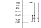
By way of example, fig. 3 is a schematic diagram of one possible design of smart PA.
As shown in fig. 3, the smart PA includes a plurality of pins. The plurality of pins are respectively: INB1 pin, INB2 pin, INB3 pin, VBAT1 pin, VBAT2 pin, OUTN pin, and OUTP pin.
The INB1 pin, the INB2 pin, the INB3 pin, the VBAT1 pin and the VBAT2 pin are all connected with the battery. The INB1 pin, the INB2 pin and the INB3 pin are used for voltage input of audio amplification processing; the VBAT1 pin and the VBAT2 pin are used for voltage detection to detect the output voltage of the battery.
The OUTN pin and the OUTP pin are both connected to a speaker. The OUTN pin and the OUTP pin are used for output of the audio amplification process.
The voltage output by the battery enters the smart PA through the INB1 pin, the INB2 pin and the INB3 pin; the amplified audio is output from the OUTN pin and the OUTP pin to the speaker.
In view of this, embodiments of the present application provide an audio circuit. The input end for detecting the battery voltage in the smart PA is connected to the voltage module, so that the smart PA cannot detect that the battery voltage drops below the working voltage, and then the loudspeaker can continue to work normally, noise or interrupt of an audio playing scene is reduced, and user experience is improved.
Fig. 4 is a schematic structural diagram of an audio circuit according to an embodiment of the present application. The audio circuit includes a battery 401, a voltage module 402, a smart PA403, and a speaker 404.
The battery 401 is connected to a first port 403a of the smart PA403, through which the battery 401 supplies power to the smart PA 403.
A second port 403b of the smart PA403 is connected to the voltage module 402, and is used for voltage detection.
The output voltage of the voltage module 402 is greater than or equal to an under-voltage lockout threshold (UVLO). The under-voltage lockout threshold (UVLO) is the minimum voltage required by the smart PA404 to maintain normal operation.
The voltage module 402 may be a module in the terminal device where the voltage is greater than or equal to an under-voltage lockout threshold, such as a DC/DC converter in a mobile communication module, or the like. The specific structure of the voltage module is not limited in the embodiments of the present application.
The smart PA404 is used for amplifying audio. The smart PA404 is also used to adjust the output dynamic range of audio, etc.
The speaker 405 is used to play audio processed by the smart PA 404. The speaker 405 is driven to play out audio.
Thus, the smart PA404 does not detect that the voltage at the input is less than its minimum operating voltage and stops operating when the battery level is low.
On the basis of the above embodiment, the electronic device further comprises a controller 405, the controller 405 being connected to the battery 401 and the smart PA403, respectively.
The controller may be a processor. The processor may be a System On Chip (SOC), a microprocessor (micro control unit, MCU), or the like. The embodiment of the application does not limit the specific structure of the controller.
The controller 405 is configured to adjust the loudness of the audio data when the battery voltage is lower than the first threshold, and send the adjusted audio data to the smart PA403 for amplification processing. Alternatively, the controller 405 is configured to adjust the gain (amplification factor) of the smart PA403 to the audio data when the battery voltage is lower than the first threshold. Thus, noise of the loudspeaker caused by failure of the undervoltage protection function can be reduced.
It will be appreciated that the controller 405 may send the adjusted audio data over an I2S data line between the controller and the smart PA 404. The controller 405 may send the first signal over an I2C data line between the controller and the smart PA 404.
The first threshold may be 2.7V, or any other value. The first threshold may be set according to actual situations or experience, and the embodiments of the present application are not limited herein with respect to a specific value of the first threshold.
Fig. 5 is a schematic structural diagram of a smart PA according to an embodiment of the present application.
As shown in fig. 5, the smart PA includes a plurality of pins. The plurality of pins are respectively: INB1 pin, INB2 pin, INB3 pin, VBAT1 pin, VBAT2 pin, OUTN pin, and OUTP pin.
Wherein, the INB1 pin, the INB2 pin and the INB3 pin are all connected with the battery. The INB1 pin, the INB2 pin and the INB3 pin are used for voltage input of audio amplification processing; the VBAT1 pin and the VBAT2 pin are connected with the voltage module, and the VBAT1 pin and the VBAT2 pin are used for detecting voltage so as to detect the output voltage of the battery.
The OUTN pin and the OUTP pin are both connected to a speaker. The OUTN pin and the OUTP pin are used for output of the audio amplification process.
The VBAT1 pin and the VBAT2 pin are connected with the voltage module, and the voltage of the voltage module is detected. The VBAT1 pin and the VBAT2 pin are not connected to the battery. Thus, the voltage detected by the smart PA is greater than the under-voltage lockout threshold (UVLO), reducing instances where the smart PA is not operating.
The voltage output by the battery enters the smart PA through the INB1 pin, the INB2 pin and the INB3 pin; the amplified audio is output from the OUTN pin and the OUTP pin to the speaker.
In some embodiments, the smart PA further comprises: FS pin, DATAO pin, DATAI pin, SCL pin, SDA pin.
The FS pin is used for inputting the digital audio frame synchronization of the I2S interface; the DATAO pin is used for outputting digital audio data of the I2S interface; the DATAI pin is used for I2S interface digital audio data input. The SCL pin is used for inputting a digital I2C bus clock; the SDA pin is used for digital I2C bus data input/output.
It will be appreciated that the controller may transmit audio data over the I2S connection and adjust the gain of the smart PA to the audio data over the I2C bus.
In some embodiments, the smart PA further comprises: VSP pin, VSN pin (not shown in the figure). Specifically, the VSP pin and the VSN pin are respectively connected to the positive electrode and the negative electrode of the speaker, and are used for measuring the voltages at two ends of the speaker so as to adjust the output of the smart PA.
It will be appreciated that in the configuration shown in fig. 5 described above, voltage detection is performed via two pins (VBAT 1 pin, VBAT2 pin). Only one pin may be set for voltage detection in the smart PA, or other numbers of pins may be set for voltage detection. The embodiments of the present application are not limited in this regard.
The embodiment of the application also provides a control method, which comprises the following steps: the controller detects that the output voltage of the battery is smaller than a first threshold value; the controller adjusts the loudness of the audio based on the first threshold and transmits the adjusted audio to the power amplifier, the loudness of the adjusted audio being less than the loudness of the audio.
In this way, the occurrence of noise in the speaker caused by the low output voltage of the battery can be reduced.
The embodiment of the application also provides a control method, which comprises the following steps: the controller detects that the output voltage of the battery is smaller than a first threshold value; the controller sends a first signal to the power amplifier based on a first threshold, the first signal being used to adjust the gain of the power amplifier to the audio, the adjusted gain being less than the gain before adjustment.
In this way, the occurrence of noise in the speaker caused by the low output voltage of the battery can be reduced.
It should be noted that, the user information (including but not limited to user equipment information, user personal information, etc.) and the data (including but not limited to data for analysis, stored data, presented data, etc.) related to the present application are information and data authorized by the user or fully authorized by each party, and the collection, use and processing of the related data need to comply with the related laws and regulations and standards of the related country and region, and provide corresponding operation entries for the user to select authorization or rejection.
The foregoing detailed description of the invention has been presented for purposes of illustration and description, and it should be understood that the foregoing is by way of illustration and description only, and is not intended to limit the scope of the invention.
Claims (7)
1. An audio circuit is characterized by comprising a battery, a voltage module, a power amplifier and a loudspeaker;
the power amplifier comprises a first port, a second port and a third port, wherein the first port is connected with the battery, the second port is connected with the voltage module, and the third port is connected with the loudspeaker;
the battery is used for supplying power to the power amplifier;
the output voltage of the voltage module is larger than or equal to a preset voltage, and the preset voltage is the minimum voltage required by the power amplifier when the power amplifier keeps working; the voltage module is a module with voltage greater than or equal to preset voltage;
the power amplifier is used for amplifying the audio when the output voltage of the battery is smaller than the preset voltage;
The loudspeaker is used for playing the audio frequency processed by the power amplifier;
the first port includes a first pin; the second port comprises a second pin and a third pin, the second pin is not connected with the first pin, and the third pin is not connected with the first pin;
the second pin and the third pin are used for detecting the output voltage of the voltage module;
the circuit further includes a controller; the battery and the power amplifier are connected with the controller;
the controller is configured to upon detecting that the output voltage of the battery is less than a first threshold,
adjusting the loudness of the audio, and transmitting the adjusted audio to the power amplifier, wherein the loudness of the adjusted audio is smaller than the loudness of the audio; or sending a first signal to the power amplifier, wherein the first signal is used for adjusting the gain of the power amplifier to the audio frequency, and the adjusted gain is smaller than the gain before adjustment.
2. The circuit of claim 1, wherein the power amplifier further comprises a fourth pin;
the fourth pin is connected with the controller and is used for transmitting the adjusted audio.
3. The circuit of claim 1, wherein the power amplifier further comprises a fifth pin;
the fifth pin is connected with the controller and is used for receiving the first signal.
4. A terminal device, characterized in that the terminal device comprises an audio circuit according to any of claims 1-3.
5. The terminal device of claim 4, further comprising a microphone for capturing sound signals.
6. A control method applied to the audio circuit of claim 1 or 2, the method comprising:
the controller detects that the output voltage of the battery is less than a first threshold;
the controller adjusts the loudness of the audio based on the first threshold and transmits the adjusted audio to the power amplifier, the loudness of the adjusted audio being less than the loudness of the audio.
7. A control method applied to the audio circuit of claim 1 or 3, the method comprising:
the controller detects that the output voltage of the battery is less than a first threshold;
the controller sends a first signal to the power amplifier based on the first threshold, the first signal being used to adjust the gain of the power amplifier to the audio, the adjusted gain being less than the gain before adjustment.
Priority Applications (1)
| Application Number | Priority Date | Filing Date | Title |
|---|---|---|---|
| CN202211645375.4A CN115665632B (en) | 2022-12-21 | 2022-12-21 | Audio circuit, related device and control method |
Applications Claiming Priority (1)
| Application Number | Priority Date | Filing Date | Title |
|---|---|---|---|
| CN202211645375.4A CN115665632B (en) | 2022-12-21 | 2022-12-21 | Audio circuit, related device and control method |
Publications (2)
| Publication Number | Publication Date |
|---|---|
| CN115665632A CN115665632A (en) | 2023-01-31 |
| CN115665632B true CN115665632B (en) | 2023-06-06 |
Family
ID=85023182
Family Applications (1)
| Application Number | Title | Priority Date | Filing Date |
|---|---|---|---|
| CN202211645375.4A Active CN115665632B (en) | 2022-12-21 | 2022-12-21 | Audio circuit, related device and control method |
Country Status (1)
| Country | Link |
|---|---|
| CN (1) | CN115665632B (en) |
Families Citing this family (1)
| Publication number | Priority date | Publication date | Assignee | Title |
|---|---|---|---|---|
| CN117135538A (en) * | 2023-02-21 | 2023-11-28 | 荣耀终端有限公司 | Speaker driving circuit and electronic device |
Citations (1)
| Publication number | Priority date | Publication date | Assignee | Title |
|---|---|---|---|---|
| CN112039447A (en) * | 2020-09-30 | 2020-12-04 | 深圳市纳芯威科技有限公司 | Audio power amplifier integrated circuit and audio equipment |
Family Cites Families (5)
| Publication number | Priority date | Publication date | Assignee | Title |
|---|---|---|---|---|
| US8406706B2 (en) * | 2010-05-20 | 2013-03-26 | Lg Electronics Inc. | Mobile terminal and method of controlling a driving voltage of a power amplifier therein |
| CN105553434A (en) * | 2015-10-28 | 2016-05-04 | 东莞酷派软件技术有限公司 | Intelligent terminal audio control method and system and intelligent terminal |
| US9917553B2 (en) * | 2016-06-20 | 2018-03-13 | Texas Instruments Incorporated | Low distortion output stage for audio amplifiers |
| JP7100476B2 (en) * | 2018-03-30 | 2022-07-13 | ローム株式会社 | Audio amplifiers, audio output devices and electronic devices using them |
| CN117917854A (en) * | 2022-10-21 | 2024-04-23 | 荣耀终端有限公司 | Audio amplification circuit, board card and electronic equipment |
-
2022
- 2022-12-21 CN CN202211645375.4A patent/CN115665632B/en active Active
Patent Citations (1)
| Publication number | Priority date | Publication date | Assignee | Title |
|---|---|---|---|---|
| CN112039447A (en) * | 2020-09-30 | 2020-12-04 | 深圳市纳芯威科技有限公司 | Audio power amplifier integrated circuit and audio equipment |
Also Published As
| Publication number | Publication date |
|---|---|
| CN115665632A (en) | 2023-01-31 |
Similar Documents
| Publication | Publication Date | Title |
|---|---|---|
| CN110750772B (en) | Electronic equipment and sensor control method | |
| CN111552451B (en) | Display control method and device, computer readable medium and terminal equipment | |
| CN112334860B (en) | Touch control method of wearable device, wearable device and system | |
| CN113395382B (en) | Method for data interaction between devices and related devices | |
| CN113676339B (en) | Multicast method, device, terminal equipment and computer readable storage medium | |
| CN115665632B (en) | Audio circuit, related device and control method | |
| CN112738794B (en) | Network residing method, chip, mobile terminal and storage medium | |
| CN113129916B (en) | Audio acquisition method, system and related device | |
| CN114554012B (en) | Incoming call answering method, electronic equipment and storage medium | |
| CN114915747B (en) | Video call method, electronic device and readable storage medium | |
| CN111309130B (en) | Mobile terminal and method for realizing water inflow protection | |
| CN117093068A (en) | Vibration feedback method and system based on wearable device, wearable device and electronic device | |
| CN116133165A (en) | Headset connection system, method, headset, electronic device, and readable storage medium | |
| CN114221402A (en) | Charging method and device of terminal equipment and terminal equipment | |
| CN116708317B (en) | Data packet MTU adjustment method and device and terminal equipment | |
| CN114520870B (en) | Display method and terminal | |
| CN116667875B (en) | Switching method and device of internet access and terminal equipment | |
| CN219834364U (en) | Audio circuit and terminal equipment | |
| CN116048769B (en) | Memory recycling method and device and terminal equipment | |
| CN116346982B (en) | Method for processing audio, electronic device and readable storage medium | |
| CN112996066B (en) | Network residing method and related equipment | |
| CN114610195B (en) | Icon display method, electronic device and storage medium | |
| CN113364067B (en) | Charging precision calibration method and electronic equipment | |
| CN116708317A (en) | Data packet MTU adjustment method and device and terminal equipment | |
| CN117793861A (en) | Mode switching method and device for near field communication and terminal equipment |
Legal Events
| Date | Code | Title | Description |
|---|---|---|---|
| PB01 | Publication | ||
| PB01 | Publication | ||
| SE01 | Entry into force of request for substantive examination | ||
| SE01 | Entry into force of request for substantive examination | ||
| GR01 | Patent grant | ||
| GR01 | Patent grant |