CN115654247A - High leakproofness has and inhales buffer who shakes function - Google Patents
High leakproofness has and inhales buffer who shakes function Download PDFInfo
- Publication number
- CN115654247A CN115654247A CN202211159252.XA CN202211159252A CN115654247A CN 115654247 A CN115654247 A CN 115654247A CN 202211159252 A CN202211159252 A CN 202211159252A CN 115654247 A CN115654247 A CN 115654247A
- Authority
- CN
- China
- Prior art keywords
- connecting pipe
- pipe
- sealing ring
- sealing
- shock
- Prior art date
- Legal status (The legal status is an assumption and is not a legal conclusion. Google has not performed a legal analysis and makes no representation as to the accuracy of the status listed.)
- Granted
Links
- 239000000872 buffer Substances 0.000 title claims abstract description 20
- 238000007789 sealing Methods 0.000 claims abstract description 104
- 230000035939 shock Effects 0.000 claims abstract description 10
- 230000008878 coupling Effects 0.000 claims abstract description 8
- 238000010168 coupling process Methods 0.000 claims abstract description 8
- 238000005859 coupling reaction Methods 0.000 claims abstract description 8
- 230000003139 buffering effect Effects 0.000 claims abstract description 4
- 238000013016 damping Methods 0.000 claims abstract description 4
- 230000000903 blocking effect Effects 0.000 claims description 23
- 239000012535 impurity Substances 0.000 claims description 13
- 239000002184 metal Substances 0.000 claims description 11
- XLYOFNOQVPJJNP-UHFFFAOYSA-N water Substances O XLYOFNOQVPJJNP-UHFFFAOYSA-N 0.000 claims description 7
- 239000013013 elastic material Substances 0.000 claims description 4
- 239000000463 material Substances 0.000 claims description 3
- 230000000694 effects Effects 0.000 abstract description 23
- 230000005540 biological transmission Effects 0.000 abstract description 9
- 239000003208 petroleum Substances 0.000 abstract description 8
- 238000010521 absorption reaction Methods 0.000 abstract description 3
- 239000002245 particle Substances 0.000 description 8
- 239000007787 solid Substances 0.000 description 8
- 238000000034 method Methods 0.000 description 5
- 230000004888 barrier function Effects 0.000 description 2
- 238000004140 cleaning Methods 0.000 description 2
- 238000001514 detection method Methods 0.000 description 2
- 238000001125 extrusion Methods 0.000 description 2
- 238000003466 welding Methods 0.000 description 2
- 230000009286 beneficial effect Effects 0.000 description 1
- 238000005520 cutting process Methods 0.000 description 1
- 238000005516 engineering process Methods 0.000 description 1
- 239000007788 liquid Substances 0.000 description 1
- 230000002035 prolonged effect Effects 0.000 description 1
- 238000007711 solidification Methods 0.000 description 1
- 230000008023 solidification Effects 0.000 description 1
- 238000001179 sorption measurement Methods 0.000 description 1
Images


Classifications
-
- Y—GENERAL TAGGING OF NEW TECHNOLOGICAL DEVELOPMENTS; GENERAL TAGGING OF CROSS-SECTIONAL TECHNOLOGIES SPANNING OVER SEVERAL SECTIONS OF THE IPC; TECHNICAL SUBJECTS COVERED BY FORMER USPC CROSS-REFERENCE ART COLLECTIONS [XRACs] AND DIGESTS
- Y02—TECHNOLOGIES OR APPLICATIONS FOR MITIGATION OR ADAPTATION AGAINST CLIMATE CHANGE
- Y02E—REDUCTION OF GREENHOUSE GAS [GHG] EMISSIONS, RELATED TO ENERGY GENERATION, TRANSMISSION OR DISTRIBUTION
- Y02E10/00—Energy generation through renewable energy sources
- Y02E10/20—Hydro energy
Landscapes
- Joints Allowing Movement (AREA)
Abstract
The invention relates to the field of petroleum pipeline connection, in particular to a high-sealing buffer device with a shock absorption function. When pipeline took place to shake, vibrations backward transmission in proper order caused the pipeline whole to take place vibrations, when the pipeline was in the shock condition for a long time, the bolt of its junction appeared not hard up, and it is poor to lead to the sealed effect of gasket, and the oil can appear in the junction reveals even the fracture. The utility model provides a high leakproofness has shock-absorbing function's buffer, includes first connecting pipe, and first connecting pipe rigid coupling has the second connecting pipe, is provided with the bellows that is used for vibrations buffering between two second connecting pipes, and the sealing washer is installed to first connecting pipe. According to the invention, the bellows is arranged to absorb and buffer transverse vibration and partial longitudinal vibration, so that vibration transmission is isolated, a better damping effect is realized, the gasket is replaced by the sealing ring, the characteristics of the original constant-diameter gasket are reserved, the contact area of the sealing ring is increased, and a better sealing effect is realized.
Description
Technical Field
The invention relates to the field of pipeline connection, in particular to a high-sealing buffer device with a shock absorption function.
Background
The pipeline connecting technology is widely applied to various petroleum and gas transmission lines, various pipeline connecting methods such as threaded connection, flange connection, welding connection and the like are available, the flange connection is convenient to use, can bear larger pressure, and the connecting part can be detached.
Present flange joint only relies on the gasket to seal, and its fixed mode is bolted connection, when pipeline takes place to shake, because current connected mode, make vibrations backward transfer in proper order, finally cause the whole vibrations that take place of pipeline, and when the pipeline is in the shock condition for a long time, the conveyer pipe that is close to vibrations source one side passes through flange joint department and directly drives conveyer pipe at the back, make flange joint department receive too big stress, the bolt of its junction appears becoming flexible, it is poor to lead to the sealed effect of gasket, the junction can appear the oil and reveal the condition such as fracture even.
In order to solve the technical problems, a buffer gasket which is high in sealing performance and capable of preventing water hammer impact and has a shock absorption function is provided.
Disclosure of Invention
When vibrations take place for solving pipeline, vibrations backward transmission in proper order causes the pipeline whole to take place vibrations, when the pipeline is in the shock condition for a long time, the bolt of its junction appears becoming flexible, leads to the sealed effect of gasket poor, and the fracture problem even can appear petroleum leakage in the junction, provides a high leakproofness that the water hammer strikes has the buffer gasket who shakes the function.
The technical scheme is as follows: the utility model provides a high leakproofness has and inhales buffer of shake function, includes the conveyer pipe, and the end difference flange joint in opposite directions of two conveyer pipes has first connecting pipe, and the one end rigid coupling that the conveyer pipe was kept away from to first connecting pipe has the second connecting pipe, is provided with the bellows that is used for vibrations buffering between two second connecting pipes, is provided with the helical baffle who is used for supplementary bellows (4) interior impurity clearance in the second connecting pipe.
Preferably, one end of the first connection pipe, which is far away from the delivery pipe, is connected with the second connection pipe ball.
Preferably, still including the supporting component, the supporting component sets up on the primary connecting pipe, and the supporting component is used for the support of second connecting pipe, and the supporting component is including the fixed block, and fixed block circumference sets up on the primary connecting pipe, and the fixed block ball joint has the head rod, and the head rod has the second connecting rod with the ball joint of second connecting pipe support, is provided with spacing subassembly between two head rods, and spacing subassembly is used for the slip of two head rods spacing.
Preferably, a sealing ring is arranged in the first connecting pipe, the sealing ring is H-shaped, one side of the sealing ring is fixedly connected with the first connecting pipe, and the other side of the sealing ring is fixedly connected with the second connecting pipe.
Preferably, the material of the sealing ring is an elastic material.
Preferably, the protection assembly is used for preventing the corrugated pipe from being impacted by a water hammer, the sealing assembly comprises a supporting plate, the supporting plate is fixedly connected in a first connecting pipe, one side, close to the corrugated pipe, of the supporting plate is fixedly connected with a tension spring, a blocking disc fixedly connected with the tension spring is arranged in the first connecting pipe in a sliding mode, shunting holes are formed in the first connecting pipe in the circumferential direction, two ends of each shunting hole are located on two sides of the blocking disc respectively, and the inner diameter of each shunting hole is equal to the diameter of the first connecting pipe.
Preferably, one side of the blocking disc close to the tension spring is set to be a curved surface with a central point lower than the circumferential direction, one side of the blocking disc far away from the tension spring is set to be a curved surface with a central point higher than the circumferential direction, and one side of the sealing ring far away from the corrugated pipe is set to be an arc-shaped curved surface matched with the blocking disc for increasing the sealing performance between the sealing ring and the blocking disc.
Preferably, the diversion holes are provided as through holes inclined to the circumferential plane of the blocking disk for initial rotation of oil before entering the helical baffle.
Preferably, the sealing device further comprises a sealing ring, the sealing ring is arranged between the conveying pipe and the flange of the first connecting pipe, a limiting groove matched with the sealing ring is formed between the conveying pipe and the flange of the first connecting pipe, the thickness of the inner annular surface and the thickness of the outer annular surface of the sealing ring are equal, the thickness of the middle portion of the sealing ring is larger than that of the outer annular surface, the contact area between the sealing ring and the conveying pipe and the flange of the first connecting pipe is increased, and a metal ring is arranged in the sealing ring.
Preferably, the cross section of the metal ring is arranged in a shuttle shape, and the sum of straight distances from the side surface of the metal ring to the outer side surface of the middle part of the sealing ring is equal to the thickness of the outer ring surface of the sealing ring.
The invention has the beneficial effects that: the invention absorbs and buffers transverse vibration and partial longitudinal vibration by arranging the corrugated pipe, so that vibration transmission is cut off, better damping effect is realized, the right-side conveying pipe only can drive the adjacent first connecting pipe to vibrate and can not directly drive the subsequent conveying pipe to vibrate, the condition that oil leaks or even breaks due to overlarge stress on the flange joint is avoided, better vibration cutting effect is realized, bolts can not be separated, the sealing ring replaces a gasket, the equal extrusion force between the side surface of the sealing ring and the conveying pipe and the first connecting pipe is ensured, the characteristic of the original constant-diameter gasket is kept, meanwhile, the contact area between the sealing ring and the conveying pipe and the flange of the first connecting pipe is increased, and better sealing effect is realized, keep away from the one end of conveyer pipe and second connecting pipe ball and with the bellows cooperation through first connecting pipe, adsorb and cushion horizontal vibrations and vertical vibrations, make the vibrations transmission cut off, better shock attenuation effect has been realized, support the second connecting pipe through supporting component, guarantee the normal use of bellows, seal the junction of first connecting pipe and second connecting pipe through the sealing ring, make when first connecting pipe takes place to rotate, still can seal between conveyer pipe and the first connecting pipe, better sealed effect has been realized, through the shutoff of barrier disc with reposition of redundant personnel hole left side gradually, stop after the contact of barrier disc left surface and sealing ring, oil no longer transmits left, avoid high-pressure oil to get into the bellows, cause the cracked problem to appear in the bellows.
Drawings
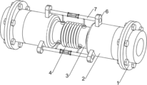
Fig. 1 is a schematic perspective view of the present invention.
Fig. 2 is a schematic perspective view of the support assembly of the present invention.
Fig. 3 is a partial cross-sectional view of a three-dimensional structure of the shield assembly of the present invention.
Fig. 4 is an enlarged schematic perspective view of the invention at a.
Reference numerals are as follows: the structure of the spiral baffle comprises a conveying pipe 1, a first connecting pipe 2, a shunt hole 201, a second connecting pipe 3, a corrugated pipe 4, a spiral baffle 5, a fixing block 6, a first connecting rod 7, a second connecting rod 8, a limiting component 9, a sealing ring 10, a supporting plate 11, a tension spring 12, a stop disc 13, a sealing ring 14 and a metal ring 15.
Detailed Description
The device is applied to petroleum pipeline connection, and the invention is further described by combining the attached drawings and an embodiment.
Example 1
The utility model provides a high leakproofness has damping function's buffer, as shown in fig. 1 and fig. 2, including conveyer pipe 1, the looks end difference flange joint of two conveyer pipes 1 has first connecting pipe 2, the one end welding that conveyer pipe 1 was kept away from to first connecting pipe 2 has second connecting pipe 3, be provided with the bellows 4 that is used for shaking the buffering between two second connecting pipe 3, bellows 4 will transversely shake and vertically shake and adsorb and cushion, make the vibrations transmission cut off, better shock attenuation effect has been realized, be provided with the helical baffle 5 that is used for assisting in the clearance of bellows (4) interior impurity in the second connecting pipe 3, when the helical baffle 5 is flowed through to oil, partial oil takes place rotatoryly, and then strike solid particle or impurity in bellows 4, avoid solid particle or impurity to pile up the solidification in bellows 4 for a long time.
The flange end that operating personnel will two first connecting pipes 2 respectively with conveyer pipe 1 flange joint, the direction that oil carried in this device is not fixed (circulation direction from right to left or from left to right all can), when one side conveyer pipe 1 takes place vibrations, declares here and all takes right side conveyer pipe 1 to take place vibrations as an example, the left side is the same reason, because first connecting pipe 2 passes through flange joint with conveyer pipe 1, right side conveyer pipe 1 vibrations can lead to following three kinds of circumstances:
1. the conveying pipe 1 drives the first connecting pipe 2 to generate transverse vibration (the transverse vibration is vibration parallel to the petroleum direction), at the moment, because the first connecting pipe 2 is fixedly connected with the second connecting pipe 3, the first connecting pipe 2 drives the corrugated pipe 4 to transversely vibrate through the second connecting pipe 3, and because the corrugated pipe 4 has scalability, the corrugated pipe 4 contracts and slows down or counteracts the transverse vibration of the second connecting pipe 3 on the right side.
2. The conveying pipe 1 drives the first connecting pipe 2 to generate longitudinal vibration (the longitudinal vibration is a process of randomly moving in a plane perpendicular to the petroleum direction), and taking the upward movement of the conveying pipe 1 as an example, the second connecting pipe 3 drives the right end of the corrugated pipe 4 to move upward, and the elasticity of the corrugated pipe 4 can still buffer the longitudinal vibration to avoid the leftward transmission of the longitudinal vibration.
3. The conveying pipe 1 drives the first connecting pipe 2 to vibrate transversely and longitudinally, and the corrugated pipe 4 buffers and cuts off vibration by means of deformation of the corrugated pipe.
Due to the special shape of the corrugated pipe 4, when oil flows through the corrugated pipe 4, part of solid particles or impurities in the oil can be intercepted by the corrugated pipe 4, and when the oil flows through the spiral baffle 5, part of the oil rotates to further impact the solid particles or impurities in the corrugated pipe 4, so that the solid particles or impurities are prevented from being accumulated and solidified in the corrugated pipe 4 for a long time, and the expansion amount of the corrugated pipe 4 is prevented from being influenced.
To sum up, adsorb and cushion horizontal vibrations and vertical vibrations through setting up bellows 4 for the vibrations transmission is cut off, has realized better shock attenuation effect, makes right side conveyer pipe 1 only can drive the vibrations of adjacent first connecting pipe 2, can not directly drive follow-up conveyer pipe 1 vibrations, avoids flange joint to receive too big stress, and the cracked condition of junction even appears leaking in the oil, realizes better vibrations and cuts off the effect, guarantees that the bolt can not break away from.
Example 2
On the basis of embodiment 1, as shown in fig. 2, one end of the first connecting pipe 2 away from the delivery pipe 1 is ball-jointed with the second connecting pipe 3.
As shown in fig. 1 and fig. 2, the supporting device further comprises a supporting component, the supporting component is arranged on the first connecting pipe 2, the supporting component is used for supporting the second connecting pipe 3, the normal use of the corrugated pipe 4 is guaranteed while the longitudinal vibration with larger amplitude is buffered or eliminated, the supporting component comprises a fixing block 6, the fixing block 6 is fixedly connected to the first connecting pipe 2 in the circumferential direction, the fixing block 6 is connected with a first connecting rod 7 in a spherical mode, the first connecting rod 7 and a support of the second connecting pipe 3 are connected with a second connecting rod 8 in a spherical mode, a limiting component 9 is arranged between the two first connecting rods 7, the limiting component 9 comprises two lantern rings and three supporting rods, the lantern rings are sleeved on the first connecting rods 6, and the limiting component 9 is used for limiting the sliding of the two first connecting rods 7.
As shown in fig. 2 and 3, a sealing ring 10 in an H shape is arranged in the first connecting pipe 2, one side of the sealing ring 10 is fixedly connected with the first connecting pipe 2, the other side of the sealing ring is fixedly connected with the second connecting pipe 3, so that the joint of the conveying pipe 1 and the first connecting pipe 2 is sealed by the sealing ring 10, the sealing ring 10 is made of an elastic material, so that when the first connecting pipe 2 rotates, the conveying pipe 1 and the first connecting pipe 2 can still be sealed, and a better sealing effect is realized.
The flange end that operating personnel will two first connecting pipes 2 respectively with conveyer pipe 1 flange joint, because first connecting pipe 2 keeps away from conveyer pipe 1's one end and 3 ball joints of second connecting pipe, support second connecting pipe 3 through setting up supporting component, guarantee the normal use of bellows 4 simultaneously and cushion or eliminate more by a wide margin longitudinal vibration, the direction that the oil carried in this device is unset (circulation direction from right to left or from left to right all can), when one side conveyer pipe 1 takes place vibrations, here declare below all take right side conveyer pipe 1 to take place vibrations as an example, the left side is the same reason, because first connecting pipe 2 passes through flange joint with conveyer pipe 1, right side conveyer pipe 1 vibrations can lead to following three kinds of circumstances:
1. conveyer pipe 1 drives first connecting pipe 2 and takes place horizontal vibrations (this state horizontal vibrations for being on a parallel with the vibrations of oil direction), first connecting pipe 2 drives head rod 7 lateral shifting through three fixed block 6, because spacing of spacing subassembly 9, make the vibrations direction of right side head rod 7 be parallel with the oil flow direction, because first connecting pipe 2 keeps away from conveyer pipe 1's one end and 3 ball joints of second connecting pipe, and second connecting rod 8 is spacing to second connecting pipe 3, make second connecting pipe 3 be parallel with second connecting rod 8 all the time, at this moment, second connecting pipe 3 drives bellows 4 horizontal vibrations, because bellows 4 has scalability, make bellows 4 shrink, slow down or offset the horizontal vibrations of right side second connecting pipe 3.
2. The conveyer pipe 1 drives the first connecting pipe 2 to generate longitudinal vibration (this longitudinal vibration is the process of randomly moving perpendicular to the petroleum direction plane), at this moment, take the conveyer pipe 1 to move upwards as an example, when the conveyer pipe 1 generates large-amplitude longitudinal vibration, the bellows 4 can not buffer all longitudinal vibration, because the one end of the first connecting pipe 2 far away from the conveyer pipe 1 is connected with the 3 ball of the second connecting pipe, through the cooperation of the second connecting pipe 3 and the bellows 4, the longitudinal vibration of the bellows 4 is eliminated, better vibration adsorption effect is realized, because the left side first connecting pipe 7 is limited by the left side fixing block 6, the conveyer pipe 1 moves upwards to enable the right end of the right side first connecting pipe 7 to be higher than the left side, meanwhile, the right end of the second connecting pipe 3 is higher than the left side, by changing the direction of the second connecting pipe 3, the longitudinal dislocation of the bellows 4 under the large-amplitude longitudinal vibration condition is avoided (the longitudinal dislocation means that one side of the bellows 4 moves along the direction perpendicular to the petroleum direction), and the service life of the bellows 4 is prolonged.
3. Conveyer pipe 1 drives first connecting pipe 2 and both carries out horizontal vibrations and carry out longitudinal vibration again, uses the horizontal vibrations that appear on the basis of the second kind of condition as the example this moment, and the longitudinal vibration is the same reason appears on the basis of the first kind of condition, and 4 right-hand members of bellows are higher than the left end, and conveyer pipe 1 takes place horizontal vibrations this moment, and the first connecting pipe 2 in right side carries out horizontal vibrations, and bellows 4 slows down horizontal vibrations, avoids longitudinal vibration to transmit left.
Because sealing ring 10 sets up to the H shape, sealing ring 10 one side and first connecting pipe 2 rigid coupling, the opposite side and the 3 rigid couplings of second connecting pipe, make sealing ring 10 seal conveyer pipe 1 and the 2 junctions of first connecting pipe, and when vibrations appear in conveyer pipe 1, first connecting pipe 2 receives the spacing emergence of conveyer pipe 1 and rotates, because the material of sealing ring 10 is elastic material, make when first connecting pipe 2 takes place to rotate, still can seal between conveyer pipe 1 and the first connecting pipe 2, better sealed effect has been realized.
Due to the special shape of the corrugated pipe 4, when oil flows through the corrugated pipe 4, part of solid particles or impurities in the oil can be intercepted by the corrugated pipe 4, and when the oil flows through the spiral baffle 5, part of the oil rotates to further impact the solid particles or impurities in the corrugated pipe 4, so that the solid particles or impurities are prevented from being accumulated and solidified in the corrugated pipe 4 for a long time, and the expansion amount of the corrugated pipe 4 is prevented from being influenced.
Example 3
On the basis of the embodiment 2, as shown in fig. 2 and fig. 3, the device further comprises a protection assembly, the protection assembly is used for preventing the corrugated pipe 4 from being impacted by a water hammer, the sealing assembly comprises a supporting plate 11, the supporting plate 11 is welded in the first connecting pipe 2, one side of the supporting plate 11, which is close to the corrugated pipe 4, is fixedly connected with a tension spring 12, a blocking disc 13 fixedly connected with the tension spring 12 is arranged in the first connecting pipe 2 in a sliding manner, when the right-side pressure is suddenly increased, the blocking disc 13 moves leftwards, one side of the blocking disc 13, which is close to the tension spring 12, is set to be a curved surface with a central point lower than the circumferential direction, high-pressure oil is gathered in the middle, high-pressure oil is prevented from being shunted to enter the shunting hole 201, a better high-pressure detection effect is realized, one side of the blocking disc 13, which is far away from the tension spring 12, is set to be a curved surface with a central point higher than the circumferential direction, one side that bellows 4 was kept away from to sealing ring 10 sets up to with block 13 complex arc curved surfaces, a leakproofness for increasing between sealing ring 10 and the block dish 13, diversion hole 201 has been seted up to the internal periphery of first connecting pipe 2, diversion hole 201 inlet and liquid outlet are located respectively and block 13 left and right sides of dish, block that dish 13 seals with diversion hole 201 shutoff and secondary and sealing ring 10 through first, form double seal, better sealed effect has been realized, diversion hole 201 sets up to the through-hole with block 13 circumference plane slopes, a preliminary rotation for getting into oil before helical baffle 5, spiral baffle 5 deuterogamies, better cleaning effect has been realized to 4 impurity of bellows, diversion hole 201 internal diameter with equal to 2 pipe diameters of first connecting pipe, the flow does not change when guaranteeing that oil flows through diversion hole 201.
As shown in fig. 3 and 4, the sealing ring device further comprises a sealing ring 14, the sealing ring 14 is arranged between the conveying pipe 1 and the flange of the first connecting pipe 2, a limiting groove matched with the sealing ring 14 is formed between the conveying pipe 1 and the flange of the first connecting pipe 2, the thicknesses of the inner annular surface and the outer annular surface of the sealing ring 14 are equal, the thickness of the middle part of the sealing ring 14 is larger than that of the outer annular surface, the contact area between the sealing ring 14 and the flanges of the conveying pipe 1 and the first connecting pipe 2 is increased, the sealing performance is improved, a metal ring 15 is arranged in the sealing ring 14, the cross section of the metal ring 15 is in a fusiform, the sum of the linear distances from the side surface of the metal ring 15 to the outer side surface of the middle part of the sealing ring 14 is equal to that of the outer annular surface of the sealing ring 14, and the deformable thickness of the middle part of the sealing ring 14 is equal to that of the two sides.
When a water hammer occurs in the delivery pipe 1, the pressure in the delivery pipe 1 suddenly increases, for example, when the water hammer occurs in the delivery pipe 1 on the right side, the pressure on the right side instantaneously increases, because the blocking disc 13 is arranged on a path where oil flows, the right side surface of the blocking disc 13 is firstly impacted by the oil and moves leftwards, because one side of the blocking disc 13 close to the tension spring 12 is arranged to be a curved surface of which the central point is lower than the circumferential direction, the blocking disc 13 gathers the high-pressure oil in the middle, the high-pressure oil is prevented from being shunted and entering the shunting holes 201, a better high-pressure detection effect is realized, the tension spring 12 is stretched, the blocking disc 13 gradually seals the left side of the shunting holes 201, when the left side surface of the blocking disc 13 is contacted with the sealing ring 10, the oil is stopped, the oil is not transmitted leftwards any more, the high-pressure oil is prevented from entering the corrugated pipe 4, the problem that the corrugated pipe 4 is cracked is caused, because the side of the sealing ring 10 far away from the corrugated pipe 4 is arranged to be an arc-shaped curved surface matched with the blocking disc 13, the sealing ring 10 and the blocking disc 13 form sealing to block oil from transmitting to the left, the blocking disc 13 blocks the shunting hole 201 for the first time and seals the shunting hole 201 and the sealing ring 10 for the second time to form double sealing to realize better sealing effect, when the pressure in the conveying pipe 1 returns to normal, the tension spring 12 drives the blocking disc 13 to move rightwards to reset, the oil continues to transmit to the left through the shunting hole 201, the inner diameter of the shunting hole 201 is equal to the pipe diameter of the first connecting pipe 2, the flow of the oil flowing through the shunting hole 201 is not changed, because the shunting hole 201 is arranged to be a through hole inclined with the circumferential plane of the blocking disc 13, the oil flowing out of the shunting hole 201 rotates, the rotating direction is the same as the rotating direction of the oil after passing through the helical baffle 5, the oil before entering the helical baffle 5 primarily rotates, and then the helical baffle 5 is matched, better cleaning effect has been realized 4 impurity of bellows.
In the process that the conveying pipe 1 and the first connecting pipe 2 are installed through flanges, the sealing ring 14 is placed between the conveying pipe 1 and the first connecting pipe 2 and used for improving the sealing performance of the conveying pipe 1 and the first connecting pipe 2, the thicknesses of the inner ring surface and the outer ring surface of the sealing ring 14 are equal, the thickness of the middle portion of the sealing ring 14 is larger than that of the outer ring surface, the original equal-diameter gasket is replaced (when the sealing ring is used, the side surface extrusion force is equal), the contact area between the sealing ring 14 and the flanges of the conveying pipe 1 and the first connecting pipe 2 is increased, the sealing performance is improved, the deformation amount of the sealing ring 14 when the sealing ring is extruded is determined by the thickness of the sealing ring 14, the cross section of the metal ring 15 is arranged in a shuttle shape, the sum of the linear distances from the side surface of the metal ring 15 to the outer side surface of the middle portion of the sealing ring 14 is equal to the thickness of the outer ring surface of the sealing ring 14, as shown in figure 4 (the following directions are all directions shown in figure 4), the left side surface and the right side surface of the sealing ring 15 are equal to the left side surface of the sealing ring 14, the thickness of the outer ring 14 is equal to the thickness of the outer ring surface of the conveying pipe 1 and the first connecting pipe 2, the sealing ring, the original equal-diameter gasket is kept, and the sealing effect is better.
The present application is described in detail above, and specific examples are applied herein to explain the principles and embodiments of the present application, and the descriptions of the above examples are only used to help understand the method and the core idea of the present application; meanwhile, for a person skilled in the art, according to the idea of the present application, there may be variations in the specific embodiments and the application scope, and in summary, the content of the present specification should not be construed as a limitation to the present application.
Claims (10)
1. A high leakproofness has a damping function's buffer, characterized by: including conveyer pipe (1), the end difference flange joint in opposite directions of two conveyer pipes (1) has first connecting pipe (2), and the one end rigid coupling that conveyer pipe (1) was kept away from in first connecting pipe (2) has second connecting pipe (3), is provided with bellows (4) that are used for the vibrations buffering between two second connecting pipes (3), is provided with spiral baffle (5) that are used for assisting impurity clearance in bellows (4) in second connecting pipe (3).
2. A highly airtight shock-absorbing cushion device as defined in claim 1, wherein: one end of the first connecting pipe (2) far away from the conveying pipe (1) is ball-jointed with the second connecting pipe (3).
3. A highly airtight shock-absorbing cushion device as defined in claim 1, wherein: still including supporting component, supporting component sets up on first connecting pipe (2), supporting component is used for the support of second connecting pipe (3), supporting component is including fixed block (6), fixed block (6) circumference sets up on first connecting pipe (2), fixed block (6) ball joint has head rod (7), head rod (7) and second connecting pipe (3) support ball joint have second connecting rod (8), be provided with between two head rods (7) spacing subassembly (9), spacing subassembly (9) are used for the slip of two head rods (7) spacing.
4. A highly airtight shock-absorbing cushion device as defined in claim 3, wherein: a sealing ring (10) is arranged in the first connecting pipe (2), the sealing ring (10) is H-shaped, one side of the sealing ring (10) is fixedly connected with the first connecting pipe (2), and the other side of the sealing ring is fixedly connected with the second connecting pipe (3).
5. The shock absorbing buffer device with high sealing performance as claimed in claim 4, wherein: the material of the sealing ring (10) is elastic material.
6. A shock-absorbing buffer with high sealing performance as claimed in claim 1, wherein: still including protection component, protection component is used for avoiding bellows (4) to receive the water hammer impact, seal assembly is including backup pad (11), backup pad (11) rigid coupling is in first connecting pipe (2), one side rigid coupling that backup pad (11) are close to bellows (4) has extension spring (12), first connecting pipe (2) internal sliding type is provided with the dish (13) that stop with extension spring (12) rigid coupling, the internal periphery in first connecting pipe (2) is provided with reposition of redundant personnel hole (201), reposition of redundant personnel hole (201) both ends are located respectively and stop dish (13) both sides, reposition of redundant personnel hole (201) internal diameter with equal first connecting pipe (2) pipe diameter.
7. A shock-absorbing buffer with high sealing performance as claimed in claim 6, wherein: stop that one side that dish (13) are close to extension spring (12) sets up to the curved surface that the central point is less than circumference, and the one side that extension spring (12) were kept away from in stopping dish (13) sets up to the curved surface that the central point is higher than circumference, and one side that bellows (4) were kept away from in sealing ring (10) sets up to the curved surface that blocks dish (13) complex for increase sealing ring (10) and the leakproofness between the dish (13) that blocks.
8. A highly airtight shock-absorbing cushion device as defined in claim 6, wherein: the diversion holes (201) are arranged as through holes inclined with the circumferential plane of the blocking disc (13) and used for preliminary rotation of oil before entering the spiral baffle (5).
9. A shock-absorbing buffer with high sealing performance as claimed in claim 1, wherein: still including sealing washer (14), sealing washer (14) set up between the flange of conveyer pipe (1) and first connecting pipe (2), set up between the flange of conveyer pipe (1) and first connecting pipe (2) with sealing washer (14) complex spacing groove, the thickness of sealing washer (14) inner ring face and outer anchor ring face equals, sealing washer (14) middle part thickness is greater than outer anchor ring face thickness, the area of contact between sealing washer (14) and conveyer pipe (1) and first connecting pipe (2) flange has been increased, be provided with becket (15) in sealing washer (14).
10. A shock-absorbing buffer with high sealing performance as claimed in claim 9, wherein: the cross section of the metal ring (15) is arranged to be shuttle-shaped, and the sum of the linear distances from the side surface of the metal ring (15) to the outer side surface of the middle part of the sealing ring (14) is equal to the thickness of the outer ring surface of the sealing ring (14).
Priority Applications (1)
| Application Number | Priority Date | Filing Date | Title |
|---|---|---|---|
| CN202211159252.XA CN115654247B (en) | 2022-09-22 | 2022-09-22 | High leakproofness has buffer of shock-absorbing function |
Applications Claiming Priority (1)
| Application Number | Priority Date | Filing Date | Title |
|---|---|---|---|
| CN202211159252.XA CN115654247B (en) | 2022-09-22 | 2022-09-22 | High leakproofness has buffer of shock-absorbing function |
Publications (2)
| Publication Number | Publication Date |
|---|---|
| CN115654247A true CN115654247A (en) | 2023-01-31 |
| CN115654247B CN115654247B (en) | 2023-10-31 |
Family
ID=84985072
Family Applications (1)
| Application Number | Title | Priority Date | Filing Date |
|---|---|---|---|
| CN202211159252.XA Active CN115654247B (en) | 2022-09-22 | 2022-09-22 | High leakproofness has buffer of shock-absorbing function |
Country Status (1)
| Country | Link |
|---|---|
| CN (1) | CN115654247B (en) |
Cited By (1)
| Publication number | Priority date | Publication date | Assignee | Title |
|---|---|---|---|---|
| CN116290220A (en) * | 2023-04-11 | 2023-06-23 | 蓝深集团股份有限公司 | Non-negative pressure water supply equipment with vibration reduction function |
Citations (9)
| Publication number | Priority date | Publication date | Assignee | Title |
|---|---|---|---|---|
| GB1023942A (en) * | 1962-05-16 | 1966-03-30 | Messrs Colvilles Ltd | Improvements in tuyere feed lines in blast furnaces |
| JP2000176227A (en) * | 1998-12-14 | 2000-06-27 | Asahi Glass Co Ltd | Connection support structure of filter tube for dust collector |
| US20110253667A1 (en) * | 2007-10-29 | 2011-10-20 | Ludwig Hiss | Expansion Seal, Especially for Gases |
| US20120074694A1 (en) * | 2009-06-08 | 2012-03-29 | Hygienic Design Group Llc | Self-aligning sanitary pipe joints and related systems |
| CN207298223U (en) * | 2017-08-09 | 2018-05-01 | 天津市津丰管业有限公司 | A kind of hot-water heating pipe |
| CN213089126U (en) * | 2020-08-27 | 2021-04-30 | 安徽威迈光机电科技有限公司 | Corrugated pipe type pipeline compensator |
| KR20210054871A (en) * | 2019-11-06 | 2021-05-14 | 곽동호 | Apparatus for sealing pipe |
| CN215635683U (en) * | 2021-06-21 | 2022-01-25 | 江苏海陆航管道设备有限公司 | High leakproofness expansion joint |
| CN216976175U (en) * | 2022-03-25 | 2022-07-15 | 姜树晓 | Water conservancy pipeline for water conservancy project |
-
2022
- 2022-09-22 CN CN202211159252.XA patent/CN115654247B/en active Active
Patent Citations (9)
| Publication number | Priority date | Publication date | Assignee | Title |
|---|---|---|---|---|
| GB1023942A (en) * | 1962-05-16 | 1966-03-30 | Messrs Colvilles Ltd | Improvements in tuyere feed lines in blast furnaces |
| JP2000176227A (en) * | 1998-12-14 | 2000-06-27 | Asahi Glass Co Ltd | Connection support structure of filter tube for dust collector |
| US20110253667A1 (en) * | 2007-10-29 | 2011-10-20 | Ludwig Hiss | Expansion Seal, Especially for Gases |
| US20120074694A1 (en) * | 2009-06-08 | 2012-03-29 | Hygienic Design Group Llc | Self-aligning sanitary pipe joints and related systems |
| CN207298223U (en) * | 2017-08-09 | 2018-05-01 | 天津市津丰管业有限公司 | A kind of hot-water heating pipe |
| KR20210054871A (en) * | 2019-11-06 | 2021-05-14 | 곽동호 | Apparatus for sealing pipe |
| CN213089126U (en) * | 2020-08-27 | 2021-04-30 | 安徽威迈光机电科技有限公司 | Corrugated pipe type pipeline compensator |
| CN215635683U (en) * | 2021-06-21 | 2022-01-25 | 江苏海陆航管道设备有限公司 | High leakproofness expansion joint |
| CN216976175U (en) * | 2022-03-25 | 2022-07-15 | 姜树晓 | Water conservancy pipeline for water conservancy project |
Cited By (2)
| Publication number | Priority date | Publication date | Assignee | Title |
|---|---|---|---|---|
| CN116290220A (en) * | 2023-04-11 | 2023-06-23 | 蓝深集团股份有限公司 | Non-negative pressure water supply equipment with vibration reduction function |
| CN116290220B (en) * | 2023-04-11 | 2023-10-24 | 蓝深集团股份有限公司 | Non-negative pressure water supply equipment with vibration reduction function |
Also Published As
| Publication number | Publication date |
|---|---|
| CN115654247B (en) | 2023-10-31 |
Similar Documents
| Publication | Publication Date | Title |
|---|---|---|
| CN115654247A (en) | High leakproofness has and inhales buffer who shakes function | |
| US2504634A (en) | Sound and vibrationproof joint for metal tubing | |
| CN211449945U (en) | Shock attenuation connecting device for municipal construction plumbing | |
| CN116557670B (en) | Elastic vibration-damping corrugated pipe device | |
| CN211624401U (en) | Anti-seismic support for pipeline | |
| CN215928744U (en) | Building heating and ventilation pipeline with airflow self-silencing function | |
| CN213040044U (en) | Reducing tee capable of reducing pipeline noise | |
| CN220320581U (en) | High-performance plate-type flat welding flange | |
| CN210687442U (en) | Temperature and pressure reduction device orifice plate mounting structure | |
| CN210344137U (en) | Ball receiving barrel buffer device of natural gas pipeline | |
| CN113309905A (en) | Heat preservation penetration device for hot chamber | |
| CN208041315U (en) | A kind of multi-direction viscoplasticity of pipeline is every vibration absorber | |
| CN113958290A (en) | Vertical switched reluctance motor directly drives oil production device | |
| CN219198504U (en) | Equal-inner-diameter wear-resistant expansion joint | |
| US1639800A (en) | Flexible joint | |
| CN218914170U (en) | Large-diameter pipeline coordinated deformation device in subsidence area | |
| CN115539749A (en) | Flange with vibration partition function | |
| CN213812436U (en) | Precession vortex flowmeter antidetonation mechanism | |
| CN219866894U (en) | Raw water pipeline automatic exhaust device | |
| CN219975783U (en) | Multifunctional pipe fitting connecting elbow | |
| JPH022032B2 (en) | ||
| CN109058640B (en) | Vacuum traffic pipeline expansion compensation interface | |
| CN220186135U (en) | Connection structure for tap water pipeline | |
| CN214092567U (en) | Prevent hydraulic oil pump of leakage | |
| CN218094815U (en) | Ventilation pipe for air purification convenient to butt joint |
Legal Events
| Date | Code | Title | Description |
|---|---|---|---|
| PB01 | Publication | ||
| PB01 | Publication | ||
| SE01 | Entry into force of request for substantive examination | ||
| SE01 | Entry into force of request for substantive examination | ||
| GR01 | Patent grant | ||
| GR01 | Patent grant |