CN115504236A - Cooperative production system and production process of oversized coil heavy copper pipe - Google Patents
Cooperative production system and production process of oversized coil heavy copper pipe Download PDFInfo
- Publication number
- CN115504236A CN115504236A CN202210973889.6A CN202210973889A CN115504236A CN 115504236 A CN115504236 A CN 115504236A CN 202210973889 A CN202210973889 A CN 202210973889A CN 115504236 A CN115504236 A CN 115504236A
- Authority
- CN
- China
- Prior art keywords
- copper pipe
- station
- tray
- assembly
- frame
- Prior art date
- Legal status (The legal status is an assumption and is not a legal conclusion. Google has not performed a legal analysis and makes no representation as to the accuracy of the status listed.)
- Pending
Links
- RYGMFSIKBFXOCR-UHFFFAOYSA-N Copper Chemical compound [Cu] RYGMFSIKBFXOCR-UHFFFAOYSA-N 0.000 title claims abstract description 161
- 239000010949 copper Substances 0.000 title claims abstract description 161
- 229910052802 copper Inorganic materials 0.000 title claims abstract description 161
- 238000004519 manufacturing process Methods 0.000 title claims abstract description 49
- 238000007599 discharging Methods 0.000 claims abstract description 13
- 238000000034 method Methods 0.000 claims abstract description 9
- 238000012805 post-processing Methods 0.000 claims abstract description 9
- 230000008569 process Effects 0.000 claims abstract description 6
- 238000012545 processing Methods 0.000 claims abstract description 5
- 230000007246 mechanism Effects 0.000 claims description 149
- XEEYBQQBJWHFJM-UHFFFAOYSA-N Iron Chemical compound [Fe] XEEYBQQBJWHFJM-UHFFFAOYSA-N 0.000 claims description 112
- 230000005540 biological transmission Effects 0.000 claims description 84
- 229910052742 iron Inorganic materials 0.000 claims description 56
- 238000004804 winding Methods 0.000 claims description 30
- 238000001514 detection method Methods 0.000 claims description 27
- 238000002372 labelling Methods 0.000 claims description 25
- 239000000463 material Substances 0.000 claims description 24
- 239000013590 bulk material Substances 0.000 claims description 19
- 239000002023 wood Substances 0.000 claims description 19
- 230000005571 horizontal transmission Effects 0.000 claims description 18
- 230000007306 turnover Effects 0.000 claims description 15
- 210000003128 head Anatomy 0.000 claims description 12
- 230000001105 regulatory effect Effects 0.000 claims description 12
- 238000010438 heat treatment Methods 0.000 claims description 10
- 239000011087 paperboard Substances 0.000 claims description 10
- 238000007639 printing Methods 0.000 claims description 9
- 230000000007 visual effect Effects 0.000 claims description 9
- 230000002093 peripheral effect Effects 0.000 claims description 7
- 238000005303 weighing Methods 0.000 claims description 6
- 238000005187 foaming Methods 0.000 claims description 5
- 238000000137 annealing Methods 0.000 claims description 4
- 238000002360 preparation method Methods 0.000 claims description 4
- 238000002203 pretreatment Methods 0.000 claims description 4
- 238000011084 recovery Methods 0.000 claims description 4
- 238000003860 storage Methods 0.000 claims description 4
- 238000007667 floating Methods 0.000 claims description 3
- 238000011179 visual inspection Methods 0.000 claims description 3
- 210000002489 tectorial membrane Anatomy 0.000 claims description 2
- 230000031877 prophase Effects 0.000 claims 2
- 238000007781 pre-processing Methods 0.000 abstract description 3
- 238000009434 installation Methods 0.000 description 15
- 238000011068 loading method Methods 0.000 description 9
- 238000003825 pressing Methods 0.000 description 9
- 230000000712 assembly Effects 0.000 description 8
- 238000000429 assembly Methods 0.000 description 8
- 238000010586 diagram Methods 0.000 description 6
- 239000000123 paper Substances 0.000 description 4
- 230000001174 ascending effect Effects 0.000 description 2
- 239000007888 film coating Substances 0.000 description 2
- 238000009501 film coating Methods 0.000 description 2
- 239000000077 insect repellent Substances 0.000 description 2
- 229920002635 polyurethane Polymers 0.000 description 2
- 239000004814 polyurethane Substances 0.000 description 2
- 229910000838 Al alloy Inorganic materials 0.000 description 1
- 241000252254 Catostomidae Species 0.000 description 1
- 229920000742 Cotton Polymers 0.000 description 1
- 238000005299 abrasion Methods 0.000 description 1
- 230000009471 action Effects 0.000 description 1
- XAGFODPZIPBFFR-UHFFFAOYSA-N aluminium Chemical compound [Al] XAGFODPZIPBFFR-UHFFFAOYSA-N 0.000 description 1
- 229910052782 aluminium Inorganic materials 0.000 description 1
- 230000009286 beneficial effect Effects 0.000 description 1
- 238000001816 cooling Methods 0.000 description 1
- 230000007547 defect Effects 0.000 description 1
- 238000012986 modification Methods 0.000 description 1
- 230000004048 modification Effects 0.000 description 1
- 230000005622 photoelectricity Effects 0.000 description 1
- 238000000926 separation method Methods 0.000 description 1
- 238000005482 strain hardening Methods 0.000 description 1
- 238000005496 tempering Methods 0.000 description 1
Images


Classifications
-
- B—PERFORMING OPERATIONS; TRANSPORTING
- B65—CONVEYING; PACKING; STORING; HANDLING THIN OR FILAMENTARY MATERIAL
- B65G—TRANSPORT OR STORAGE DEVICES, e.g. CONVEYORS FOR LOADING OR TIPPING, SHOP CONVEYOR SYSTEMS OR PNEUMATIC TUBE CONVEYORS
- B65G47/00—Article or material-handling devices associated with conveyors; Methods employing such devices
- B65G47/74—Feeding, transfer, or discharging devices of particular kinds or types
- B65G47/90—Devices for picking-up and depositing articles or materials
- B65G47/91—Devices for picking-up and depositing articles or materials incorporating pneumatic, e.g. suction, grippers
-
- B—PERFORMING OPERATIONS; TRANSPORTING
- B65—CONVEYING; PACKING; STORING; HANDLING THIN OR FILAMENTARY MATERIAL
- B65G—TRANSPORT OR STORAGE DEVICES, e.g. CONVEYORS FOR LOADING OR TIPPING, SHOP CONVEYOR SYSTEMS OR PNEUMATIC TUBE CONVEYORS
- B65G47/00—Article or material-handling devices associated with conveyors; Methods employing such devices
- B65G47/22—Devices influencing the relative position or the attitude of articles during transit by conveyors
- B65G47/24—Devices influencing the relative position or the attitude of articles during transit by conveyors orientating the articles
- B65G47/248—Devices influencing the relative position or the attitude of articles during transit by conveyors orientating the articles by turning over or inverting them
-
- B—PERFORMING OPERATIONS; TRANSPORTING
- B65—CONVEYING; PACKING; STORING; HANDLING THIN OR FILAMENTARY MATERIAL
- B65G—TRANSPORT OR STORAGE DEVICES, e.g. CONVEYORS FOR LOADING OR TIPPING, SHOP CONVEYOR SYSTEMS OR PNEUMATIC TUBE CONVEYORS
- B65G47/00—Article or material-handling devices associated with conveyors; Methods employing such devices
- B65G47/74—Feeding, transfer, or discharging devices of particular kinds or types
Landscapes
- Engineering & Computer Science (AREA)
- Mechanical Engineering (AREA)
- Specific Conveyance Elements (AREA)
Abstract
The invention relates to the technical field of copper pipe processing, in particular to a cooperative production system for an oversized coil heavy copper pipe. The invention discloses a cooperative production system for an oversized coil heavy copper pipe, which comprises a pre-processing area and a post-processing area, wherein the pre-processing area comprises a feeding station, a lifting station, a coil stacking station and a tray discharging station which are sequentially arranged; the production process of the copper pipe cooperative production system is also provided, the process flow is simple, the production efficiency and the yield of the copper pipe are greatly improved, and the produced copper pipe has stable quality and reliable performance.
Description
Technical Field
The invention relates to the technical field of copper pipe processing, in particular to a cooperative production system and a production process of an oversized coil heavy copper pipe.
Background
The copper pipe conventionally used by current air conditioner manufacturers is a coil pipe which is horizontally wound, the weight of a single coil is about 160kg generally, materials need to be changed frequently when a customer uses the copper pipe, and the problem of 'paying off and pipe clamping' is easy to occur, so that the production efficiency is influenced. Therefore, a new winding mode similar to the mosquito-repellent incense coil is developed, the arrangement has no strict matching position relation, the mosquito-repellent incense coil is called as a large loose coil, and the weight of a single coil reaches 1000kg. The copper tubes produced in this new winding method are hard tubes due to work hardening, and if soft, such products must be annealed as necessary. After annealing is finished, the large loose copper coil pipes on the bracket and the iron support are lifted together by the feeding mechanism and placed on a tray conveyor, and a finished product is obtained after the protection film is wound and labeled. The iron support is adopted as a bearing tool for carrying out in-furnace operation during annealing, and the wooden support is required to be adopted for delivery when leaving a factory, so that the iron support at the bottom of the original finished product is replaced by the wooden support with the paper disc through a special disc replacing device, the replaced iron support is grabbed by a robot and placed at the recovery position of the iron support, the wooden support is grabbed by the robot and placed on a conveyor, and the paper disc on the wooden support is placed on the wooden support in a sucking mode.
Because the large loose coil is directly scattered into a hollow cylindrical structure by one or more copper pipes, the loose coil is easy to be scattered and even overturned by any negligence of turnover and lifting before the package and fixation are finished. At present, no production line for producing copper pipes in a new winding mode exists in the market, and the production line is particularly critical for feeding, tray changing and robot grabbing devices which can affect the quality of the copper pipes.
Disclosure of Invention
The technical problem to be solved by the invention is as follows: the defect that no production line for producing the copper pipe in a new winding mode exists in the prior art is overcome, and a cooperative production system for the oversized coil heavy copper pipe capable of realizing the new winding mode is provided.
The technical scheme adopted by the invention for solving the technical problem is as follows: a cooperative production system for an oversized coil heavy copper pipe comprises:
the pre-treatment area comprises a feeding station, a lifting station, a disc stacking station and a tray discharging station which are sequentially arranged, a pallet conveyor, a gantry feeding machine, a bulk disc material rack conveyor and a disc stacking machine, wherein the gantry feeding machine, the bulk disc material rack conveyor and the disc stacking machine are arranged corresponding to the lifting station, the pallet conveyor, the bulk disc material rack conveyor and the disc stacking machine are arranged corresponding to the disc stacking station, the feeding station and the tray discharging station are respectively arranged at two ends of the pallet conveyor, the disc stacking machine is arranged on the pallet conveyor, the bulk disc material rack conveyor and the pallet conveyor are arranged in parallel, the gantry feeding machine is arranged between the pallet conveyor and the bulk disc material rack conveyor,
the post-processing area comprises a copper pipe blanking station, a film covering winding station, a labeling station, a turnover wood changing tray station, a robot grabbing station, an iron disc blanking station, a paperboard feeding station and a wood tray storage station which are sequentially arranged, and a tray conveyor and a gantry unloader which correspond to the copper pipe blanking station, the film covering winding machine, a printing labeling machine, a tray overturning device and a robot grabbing device which correspond to the copper pipe blanking station, the gantry unloader is arranged at the input port of the tray conveyor, and the film covering winding machine, the printing labeling machine, the tray overturning device and the robot grabbing device are sequentially arranged on one side of the tray conveyor.
Furthermore, a copper pipe head and tail pretreatment station and a weighing station are arranged between the copper pipe blanking station and the film covering winding station of the post-processing area, and a visual detection station is also arranged between the labeling station and the overturning wood changing support station.
The copper pipe head and tail pretreatment station cuts off the head and the tail of the copper pipe, the weighing station is used for weighing the copper pipe, and the visual detection station is used for detecting information of a labeling position and a label.
Furthermore, the gantry feeding machine comprises a gantry frame and a copper pipe carrying device arranged on the gantry frame in a sliding mode, the copper pipe carrying device comprises a horizontal transmission mechanism, a lifting mechanism and a positioning mechanism, the horizontal transmission mechanism moves back and forth along the gantry frame, the lifting mechanism is installed on the horizontal transmission mechanism, and the positioning mechanism is arranged below the horizontal transmission mechanism and connected with the lifting mechanism.
The positioning mechanism is used for positioning the copper pipe, the lifting mechanism is used for lifting the copper pipe positioned by the positioning mechanism, and the horizontal transmission mechanism is used for conveying the lifted copper pipe from one conveyor (or station) to another conveyor (or another station).
Furthermore, be equipped with the passageway that supplies horizontal transmission mechanism to remove on the portal frame, horizontal transmission mechanism includes fly leaf, servo motor, drive sprocket, chain, driven sprocket, slide rail and slider, servo motor installs the one end at the portal frame, and its output is connected with the output shaft, and drive sprocket is installed at the both ends of output shaft, and the other end swing joint of portal frame has driven sprocket, driven sprocket passes through the chain and is connected with drive sprocket, be connected with the fly leaf on the chain, the both sides of fly leaf are connected with the slider, the slider sets up on the slide rail, the slide rail is fixed on the portal frame of passageway both sides.
The output shaft is driven to rotate through the servo motor, the driving chain wheel is driven to rotate, the driven chain wheel is driven to rotate through the chain, and the movable plate reciprocates along the sliding rail through the sliding block.
Furthermore, the lifting mechanism comprises an electric cylinder, a movable frame, a first guide rod assembly and a second guide rod assembly, the electric cylinder is installed on the movable plate, the movable frame comprises an upper connecting plate and a lower connecting plate, the upper connecting plate is connected with the first guide rod assembly at the edge, the first guide rod assembly partially penetrates through the movable plate, the lower connecting plate is connected with the second guide rod assembly at the edge, the second guide rod assembly partially penetrates through the upper connecting plate, the output end of the electric cylinder penetrates through the upper connecting plate and is connected with the lower connecting plate, and the bottom of the lower connecting plate is connected with the positioning mechanism.
The lower connecting plate of the movable frame is driven by the electric cylinder to ascend or descend, and the first guide rod assembly and the second guide rod assembly realize the up-and-down movement with large stroke.
Furthermore, the positioning mechanism comprises a driving cylinder assembly, a positioning module which is driven by the driving cylinder assembly to be attached to the inner wall of the copper pipe, and a bearing module which is positioned at the bottom of the positioning module and supports the iron support, wherein the positioning module comprises a central shaft, a telescopic mechanism and a plurality of positioning blocks, one end of the central shaft is fixed on the driving cylinder assembly, the telescopic mechanism is arranged on the outer circumference of the central shaft, the positioning blocks are arc-shaped plates and connected on the telescopic mechanism, and a foaming material layer is arranged on the outer side wall of each positioning block;
the telescopic mechanism comprises at least one linear guide rail group, guide blocks and a connecting rod assembly, the linear guide rail groups are distributed from top to bottom, each linear guide rail group consists of linear guide rails with the same number as the positioning blocks, the linear guide rails are vertically arranged at the same height of the peripheral wall of the central shaft and are uniformly distributed, each linear guide rail is provided with the guide block which slides up and down along the linear guide rail, the connecting rod assembly comprises a first connecting rod, a second connecting rod and a fixed seat, one end of the first connecting rod is hinged with the guide block, the other end of the first connecting rod is connected with the inner side wall of the positioning block in a shaft way, one end of the second connecting rod is hinged to the middle section of the first connecting rod, the other end of the second connecting rod is hinged with the fixed seat, the fixed seat is fixed on the peripheral wall of the central shaft below the linear guide rails,
the driving cylinder assembly comprises a cylinder mounting frame and a self-locking cylinder, the cylinder mounting frame is connected with the lower connecting plate, the self-locking cylinder is mounted in the cylinder mounting frame, the output end of the self-locking cylinder is connected with a pushing frame through a floating joint, the pushing frame is contacted with or separated from a guide block arranged on any linear guide rail in a linear guide rail group at the uppermost part of the central shaft,
the bearing module includes location cylinder, support utensil and regulating block, the output of location cylinder passes through the regulating block and is connected with the support utensil, the bottom at the locating piece is installed to the location cylinder, the regulating block wears to locate in the through-hole of locating piece bottom and rather than sliding fit, and one side extension of regulating block bottom sets up a limiting plate.
The output end of the self-locking cylinder drives the pushing frame to move downwards so as to push any guide block to slide downwards along the linear guide rail, meanwhile, other guide blocks slide downwards along the linear guide rail, so that the bottom end of the first connecting rod is outwards expanded by the first connecting rod with one end of the second connecting rod as a fulcrum, and the other end of the second connecting rod moves downwards so as to outwards expand the positioning block until the outer side wall of the positioning block is attached to and tensioned with the inner circumferential wall of the large bulk winding copper pipe; the output end of the positioning air cylinder pushes the adjusting block to further synchronously push the support tool to move outwards until the support tool completely supports the iron support, so that the positioning mechanism can clamp the large loose-coil copper pipe.
Further, tray turning device includes the frame, the frame is close to the well section and transversely is provided with rotatory supporting mechanism, be fixed with copper pipe clamp embracing mechanism on the rotatory supporting mechanism, the top that copper pipe clamp embraced the mechanism is equipped with copper pipe roof pressure mechanism, is located the tray rotary mechanism who is equipped with transmission device and is located the transmission device below in the frame of copper pipe clamp embracing mechanism front side, tray rotary mechanism passes through the rotating member and is connected with rotatory supporting mechanism, installs the first driving piece of being connected with the rotating member on the trailing flank that copper pipe clamp embraced the mechanism, and drive rotatory supporting mechanism pivoted second driving piece is installed to the frame rear side.
Further, rotatory supporting mechanism includes the pivot and rotates the rotating member of connection in the middle of the pivot, the rotating member passes through the bearing and installs in the pivot, and the rotating member includes the rotatory journal stirrup of being connected with first driving piece and the link of being connected with tray rotary mechanism, it all is equipped with rotation angle detection assembly to be close to tip and rotating member department in the pivot, rotation angle detection assembly includes the semicircle board, a plurality of rotation angle detection sensor are installed to the border of semicircle board.
The rotating part is driven to rotate around the rotating shaft through the first driving part, and then the tray rotating mechanism connected with the connecting frame of the rotating part is driven to rotate. The double-speed operation and the accurate stop are realized through the position signals of the rotation angle detection assemblies measured by the rotation angle detection sensors, and the matching of the rotation shaft and the rotation angle of the rotating part is realized through the rotation angle signals measured by the rotation angle sensors on the two rotation angle detection assemblies.
Furthermore, the copper pipe clamping mechanism comprises an installation frame and an arc-shaped support, the arc-shaped support is fixed on the front side of the installation frame, a flexible material layer is arranged on the outer side wall of the arc-shaped support, installation wing plates are respectively fixed on two sides of the bottom of the installation frame, each installation wing plate is provided with a sleeve sleeved to the end portion of the rotating shaft, a connecting plate is fixedly arranged on each sleeve, and the connecting plate is connected with the second driving piece;
copper pipe roof pressure mechanism is including the circular clamp plate that is located arc support top and install the lifting unit on the mounting bracket, the radius of circular clamp plate is the same with the radius of arc support, lifting unit includes elevator motor, chain, sprocket I, sprocket II, sliding block and sliding guide, elevator motor installs at the top of mounting bracket, and the transmission shaft is connected to its output, the both ends of transmission shaft are equipped with sprocket I, sprocket II is installed to the bottom of mounting bracket, sprocket II passes through the chain and is connected with sprocket I, be connected with a link on the chain, sliding guide is installed at the both sides border of mounting bracket, all is equipped with the sliding block that slides along its top and bottom on two sliding guide, and two sliding blocks are fixed on the link, the link is connected with circular clamp plate, and junction between them is equipped with pressure sensor.
The copper pipe is limited axially by the arc-shaped support, and the flexible material layer plays a role in protecting the copper pipe; the connecting plate is pushed by the second driving piece to drive the sleeve to rotate around the rotating shaft, and then the installation wing plate drives the installation frame to rotate. The lifting motor is started to drive the transmission shaft to rotate, the connecting frame is driven to move up and down through the driving chain wheel, the chain and the driven chain wheel, and in order to ensure the stability of the up-and-down movement, the sliding block on the connecting frame moves along the sliding rail, so that the lifting of the circular pressing plate is realized; the pressure sensor can detect the contact pressure of the circular pressing plate and the upper end of the copper pipe, so that reasonable pressure is ensured, and the copper pipe is not damaged; the radius of the circular pressing plate is the same as that of the arc-shaped support, so that the clamping consistency is ensured.
Furthermore, the tray rotating mechanism comprises a bracket, a jacking electric push rod and a guide post, the jacking electric push rod is arranged in the middle of the back of the bracket, and the guide post is arranged on the upper surface of the bracket and connected with the transmission mechanism;
the transmission device comprises a transmission frame, a transmission shaft, a transmission chain and a servo motor I, wherein the servo motor I is arranged at one side end part of the transmission frame and connected with the transmission shaft, the transmission shaft is arranged at one end of the transmission frame, transmission chain wheels are arranged at two ends of the transmission shaft, a guide frame for supporting the transmission chain is arranged at the top of the transmission frame, chain wheels are arranged at two ends of the guide frame, the chain wheels are connected with the transmission chain wheels through the transmission chain, side positioning plates are fixed at two sides of the transmission frame, and a pressing cylinder is arranged in the middle of the side positioning plates.
Copper pipe side locating plate is connected with transmission device, realizes wholly descending through jacking electric putter, can coordinate because the difference in height that the wooden block thickness is greater than the iron support and brings. The transmission shaft is driven to rotate by starting the servo motor I, the transmission chain is driven to rotate by the transmission chain wheel and the chain wheel, the iron support is separated from the transmission mechanism, and the pressing cylinder can be used for fixing the iron support and the wood support, so that the iron support and the wood support can be overturned conveniently.
Further, the robot gripping device comprises a supporting plate, at least one group of beam assemblies are fixed to the top of the supporting plate, clamping jaw assemblies are movably mounted at two ends of each beam assembly respectively, driving clamping jaw assemblies are mounted on the beam assemblies and rotate to achieve clamping of the driving assemblies, a plurality of vacuum suckers are uniformly distributed on the bottom surface of the supporting plate, and a connecting piece connected with the joint robot is arranged in the middle of the supporting plate. The vacuum chuck is connected with the vacuum generator, the vacuum generator is installed on the supporting plate, and the height of the vacuum generator is smaller than that of the connecting piece.
Furthermore, the beam assembly is provided with a group, the beam assembly consists of two beams which are arranged in parallel, the clamping jaw assembly comprises a rotating shaft which is movably connected below the end parts of the two beams, the rotating shaft is perpendicular to the beams, a linkage part connected with the driving assembly is sleeved on the rotating shaft, fingers which are symmetrically arranged are arranged at two ends of the rotating shaft, each finger comprises a finger body with an L-shaped structure, each finger body comprises a vertical section and a transverse section positioned at the lower end of the vertical section, a notch is formed in the end part of the free end of the transverse section, each linkage part comprises a lantern ring and a connecting plate fixedly arranged on the outer side of the lantern ring, the lantern ring is tightly matched with the rotating shaft, and the connecting plates are in a 7-shaped structure;
the driving assembly comprises a cylinder mounting seat and a cylinder, the cylinder mounting seat is of an L-shaped structure and is fixed on the inner side wall of the cross beam, the tail end of the cylinder is mounted on the cylinder mounting seat, the front end of the cylinder is limited on the cross beam through a limiting pin, so that the cylinder is parallel to the cross beam, and a push rod of the cylinder is connected with the end part of the connecting plate through a connecting head in a pin joint mode.
The crossbeam adopts the aluminium alloy, and the installation of its self, drive assembly and clamping jaw subassembly of being convenient for is fixed. The driving assembly drives the linkage piece to drive the rotating shaft to rotate so as to realize the outward expansion and the furling of the fingers. Because the wooden block is much thicker than the iron block, the edge of the wooden block is directly clamped by the finger body, and the iron block can be clamped by the gap against the peripheral surface of the iron block. The connecting plate is arranged to be in a 7-shaped structure, and can play a role in limiting the rotating angle of the rotating shaft. The air cylinder is arranged in parallel with the cross beam and is fixed on the inner side of the cross beam, so that the installation space is saved, and the interference with the joint robot is avoided; the push rod of the cylinder is connected with the end part of the connecting plate in a pin joint mode, and the installation is convenient.
Furthermore, the beam assembly comprises a first beam assembly and a second beam assembly which are vertically distributed, the first beam assembly comprises two first beams which are arranged in parallel, the second beam assembly comprises four second beams, the length of each second beam is smaller than that of each first beam, the two second beams are arranged in parallel and fixed on the outer side of one first beam, and the other two second beams are arranged in parallel and fixed on the outer side of the other first beam.
The invention also provides a production process of the cooperation production system of the oversized coil heavy copper pipe in the scheme, which comprises the following process steps;
pre-treatment:
(1) The intelligent transportation equipment forks the tray loaded with the iron support and the copper pipe in the copper pipe preparation area on a pallet conveyor, and the pallet conveyor automatically conveys the pallet loaded with goods to the loading position of a gantry loading machine;
(2) The copper pipe with the iron support is automatically lifted by the gantry feeding machine and is placed on a bulk material rack of the bulk material rack conveyor, and the copper pipe enters the heat treatment furnace along with the bulk material rack conveyor for tempering;
(3) The empty trays are conveyed to a tray stacking machine for automatic stacking and dragging, the trays enter a tray discharging station after stacking and dragging are completed, and intelligent conveying equipment takes the stacked trays away;
post-processing:
(a) After the copper pipe is returned out, lifting the copper pipe on the bulk material rack together with the iron pallet by a gantry unloader and placing the copper pipe on a pallet conveyor;
(b) The copper pipe provided with the iron support is conveyed by a tray conveyor, the tray conveyor is provided with a section of copper pipe head and tail pretreatment station for manual treatment, the iron support provided with the copper pipe automatically enters the station, and after the automatic treatment is completed, the tray conveyor automatically conveys a finished product to the next section of visual inspection station;
(c) After the visual inspection is finished, the copper pipe enters a film covering and winding station, the equipment firstly covers the film and then winds the film, and the bottommost copper pipe can be ensured to be wound on the iron support and cannot be wound on the iron support during winding;
(d) After winding, the finished product enters a labeling station, and a printing and labeling machine automatically pastes labels with information such as weight, batch and the like on the outer surface of the finished product package;
(e) After labeling is finished, the finished product automatically enters a turning and converting wooden support station, the finished product and an iron support are together turned by a tray turning device, the iron support is replaced by the wooden support with a paperboard after turning is finished, and the finished product is automatically turned to the original position by the tray turning device and then conveyed to a blanking station after replacement is finished;
(f) The wooden block is placed on the tray conveyor by the robot gripping device, the replaced iron block is gripped by the robot gripping device and placed at the iron block recovery position, and the paper board on the wooden block is sucked by the robot gripping device and placed on the wooden block.
The invention has the beneficial effects that:
1. the cooperative production system has reasonable layout, small occupied area, intelligent operation in the whole process, accurate control and high production efficiency;
2. the inner wall of the large bulk copper pipe is tensioned by expanding the positioning block outwards through the positioning mechanism of the gantry feeding machine, the shape of the large bulk copper pipe is kept, the iron support at the bottom of the large bulk copper pipe is supported by combining the supporting mechanism, the large bulk copper pipe is stably clamped, the large bulk copper pipe is prevented from being inclined or even overturned, and the large bulk copper pipe can stably move in the carrying process through the arrangement of the horizontal transmission mechanism and the lifting mechanism, so that the quality and the safety of the large bulk copper pipe in the carrying process are ensured; the first guide pillar assembly and the second guide pillar assembly ensure that the lifting mechanism ensures the stability of the large loose-coil copper pipe in the lifting process, and the bearing capacity of the lifting mechanism is improved; the outer side wall of the positioning block is provided with the foaming material layer, so that abrasion of the positioning block and the large bulk copper pipe due to rigid contact is avoided, and the quality of a finished product of the large bulk copper pipe is ensured;
3. the rotation of the rotary supporting mechanism is driven by the second driving piece on the tray overturning device, so that the copper pipe clamping mechanism, the transmission mechanism and the tray rotating mechanism are driven to integrally overturn, the rotating piece is driven to rotate by the first driving piece, so that the transmission mechanism and the tray rotating mechanism are driven to overturn, the separation of the iron support from the transmission mechanism is facilitated, and the wood support and the paperboard are also convenient to place;
4. the clamping jaw assembly is driven to rotate by a driving assembly of the robot gripping device to realize the clamping action, the structure of the clamping jaw assembly can simultaneously realize the clamping of the iron support and the wood support, and the vacuum chuck can realize the suction of the paper tray;
5. the production process flow of the copper pipe cooperative production system is simple, the production efficiency and the yield of the copper pipe are greatly improved, and the produced copper pipe has stable quality and reliable performance.
Drawings
The invention is further illustrated with reference to the following figures and examples.
FIG. 1 is a schematic structural diagram of an embodiment of the present invention.
Fig. 2 is an enlarged schematic view of the pretreatment area in fig. 1.
Fig. 3 is an enlarged schematic view of the post-processing section of fig. 1.
Fig. 4 is a schematic structural diagram of a gantry loading frame in the invention.
Fig. 5 is a schematic structural diagram of the horizontal transmission mechanism in the gantry loading frame of the invention.
Fig. 6 is a schematic structural diagram of a lifting mechanism in the gantry loading frame of the invention.
Fig. 7 is a schematic structural diagram of a positioning mechanism in the gantry feeding frame of the invention.
Fig. 8 isbase:Sub>A sectional view in the directionbase:Sub>A-base:Sub>A of fig. 7.
Fig. 9 is a top view of fig. 8.
Fig. 10 is a schematic structural view of the tray turnover device of the present invention.
Fig. 11 is a schematic view of the structure of fig. 10 in the B direction.
Fig. 12 is a schematic structural view of a rotation support mechanism in the tray turnover device of the present invention.
Fig. 13 is a schematic structural view of a copper pipe clamping mechanism and a copper pipe jacking mechanism in the tray turnover device of the present invention.
Fig. 14 is a schematic view of the structure of fig. 13 in the direction C.
Fig. 15 is a schematic structural view of a tray rotating mechanism in the tray turnover device of the present invention.
Fig. 16 is a schematic structural view of a transfer mechanism in the tray turnover device of the present invention.
Fig. 17 is a schematic view of the structure of fig. 16 in the direction D.
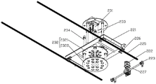
Fig. 18 is a schematic structural view of the robot gripping device of the present invention.
Fig. 19 is a side view of fig. 18.
Fig. 20 is a side view in the other direction of fig. 18.
Fig. 21 is a top view of fig. 18.
Fig. 22 is a schematic structural diagram of another embodiment of the robot gripping device in the present invention.
FIG. 23 is a flow chart of a manufacturing process according to one embodiment of the present invention.
FIG. 24 is a flow chart of a manufacturing process according to another embodiment of the present invention.
In the figure:
1. pallet conveyor, 2 gantry feeding machine, 3 bulk pallet material rack conveyor, 5 pallet conveyor, 6 gantry unloading machine, 7 heat treatment furnace, 9 pallet turning device, 10 robot gripping device,
A. the device comprises an early-stage treatment area, a copper pipe preparation area, a post-stage treatment area, a copper pipe finished product area, a loading station, a lifting station, a disc stacking station, a tray discharging station, a copper pipe blanking station, a film coating winding station, a labeling station, a turning wooden support changing station, a robot grabbing station, an iron disc blanking station, a paperboard feeding station, a wooden support storage station, a copper pipe head and tail pretreatment station, a weighing station, a visual detection station,
21. portal frame, 211, channel, 22, horizontal transmission mechanism, 221, movable plate, 222, servo motor, 223, driving chain wheel, 224, driven chain wheel, 225, slide rail, 226, slide block, 227, output shaft, 23, lifting mechanism, 231, electric cylinder, 232, movable frame, 233, first guide rod assembly, 234, second guide rod assembly, 2321, upper connecting plate, 2322, lower connecting plate, 24, positioning mechanism, 240, foaming material layer, 241, central shaft, 242, telescopic mechanism, 2422, guide block, 2421, linear guide rail, 2423, first connecting rod, 2424, second connecting rod, 2425, fixed seat, 243, positioning block, 244, cylinder mounting frame, 245, self-locking cylinder, 246, pushing frame, 247, positioning cylinder, 248, support tool, 249, adjusting block, 2410, limiting plate,
91. frame, 911, bottom frame, 912, first support column, 913, second support column, 92, rotating support mechanism, 921, rotating member, 9211, rotating lug, 9212, connecting frame, 922, rotating shaft, 923, rotating angle detection component, 9231, semicircular plate, 9232, rotating angle detection sensor, 93, copper pipe clamping mechanism, 931, mounting frame, 932, arc-shaped support, 933, mounting wing, 9331, sleeve, 9332, connecting plate, 94, copper pipe pressing mechanism, 941, circular pressing plate, 942, lifting motor, 943, sprocket I,944, sprocket II,945, slider, 946, sliding rail, 947, transmission shaft, 948, connecting frame, 949, pressure sensor, 95, transmission mechanism, 951, transmission frame, 952, transmission shaft, 953, servo motor, 954, transmission sprocket, 955, guide frame, 956, sprocket, 957, side positioning plate, 958, pressing cylinder, 96, pallet 962, rotating mechanism, bracket, lifting column, 98, driving member, 9699, 99,
101. the vacuum chuck assembly comprises a supporting plate, a beam 102', a first beam, a beam 102', a second beam, a clamping jaw assembly, a driving assembly, a vacuum chuck 105, a vacuum chuck 106, a connecting piece 1031, a rotating shaft 1032, a linkage piece 10321, a sleeve ring 10322, a connecting plate 1033, a finger 10331, a vertical section 10332, a transverse section 103321, a notch 1031, an air cylinder mounting seat 1042, an air cylinder 1043, a limiting pin 1044 and a connecting head.
Detailed Description
The invention will now be further described with reference to the accompanying drawings and preferred embodiments. These drawings are simplified schematic views illustrating only the basic structure of the present invention in a schematic manner, and thus show only the constitution related to the present invention.
As shown in fig. 1, an embodiment of the cooperative production system for super large heavy copper coil pipes includes a pre-treatment area a, a copper pipe preparation area B, a post-treatment area C and a copper pipe finished product area D, which are collectively disposed together, and an external circulation transmission system is disposed around these areas, and the external circulation transmission system includes a bulk material rack conveyor 3, a furnace feeding transmission rack and a furnace discharging transmission rack connected to the bulk material rack conveyor 3, the furnace feeding transmission rack and the furnace discharging transmission rack are respectively disposed at an inlet and an outlet of a heat treatment furnace 7, an automatic transmission mechanism is disposed in the heat treatment furnace 7, that is, a circulation transmission is formed, and the heat treatment furnace 7 includes a heating chamber and a cooling chamber;
as shown in fig. 2, the preprocessing area a includes a feeding station E, a lifting station F, a pallet stacking station H, a pallet discharging station J, a pallet conveyor 1, a gantry feeder 2, a bulk material rack conveyor 3, and a pallet stacking machine, wherein the feeding station E and the pallet discharging station J are sequentially disposed, the gantry feeder 2, the bulk material rack conveyor 3, and the pallet stacking machine are disposed corresponding to the lifting station F, the feeding station E and the pallet discharging station J are respectively disposed at two ends of the pallet conveyor 1, the pallet stacking machine is disposed on the pallet conveyor 1, the bulk material rack conveyor 3 is disposed in parallel with the pallet conveyor 1, and the gantry feeder 2 is disposed between the pallet conveyor 3 and the bulk material rack conveyor 1;
as shown in fig. 3, the post-processing area includes a copper pipe blanking station K, a film winding station L, a labeling station M, a turning wood pallet changing station N, a robot grabbing station S, an iron plate blanking station P, a paper plate feeding station Q and a wood pallet storage station R, as well as a tray conveyor rear 5 and a gantry unloader 6 which are arranged corresponding to the blanking station K, a film winding machine which is arranged corresponding to the film winding station L, a printing and labeling machine which is arranged corresponding to the labeling station M, a tray overturning device 9 which is arranged corresponding to the turning wood pallet changing station N and a robot grabbing device 10 which is arranged corresponding to the robot grabbing station S, the gantry unloader 6 is arranged at an input port of the tray conveyor 5, and the film winding machine, the printing and labeling machine, the tray overturning device 9 and the robot grabbing device 10 are arranged in sequence on one side of the tray conveyor 5.
In addition, a copper pipe head and tail pretreatment station T and a weighing station U are arranged between a copper pipe blanking station K and a film covering winding station L of the blanking processing area, and a visual detection station W is arranged between the labeling station M and the overturning wood changing support station N. Wherein, longmen material loading machine 2 is the same with longmen unloader 6's structure, fold a set machine, tectorial membrane coiler, print labeller, weigh the weighing-appliance of station U and the visual detection device of visual detection station W and all can adopt the structure among the prior art, do not give unnecessary details here.
As shown in fig. 4, the gantry feeding machine 2 includes a gantry 21 and a copper tube conveying device slidably disposed on the gantry 21, the copper tube conveying device includes a horizontal transmission mechanism 22 reciprocating along the gantry 21, a lifting mechanism 23 and a positioning mechanism 24, the lifting mechanism 23 is mounted on the horizontal transmission mechanism 22, and the positioning mechanism 24 is disposed below the horizontal transmission mechanism 22 and connected to the lifting mechanism 23. As shown in fig. 2 and 3, the horizontal transmission mechanism 22 includes a movable plate 221, a servo motor 222, a driving sprocket 223, a chain (not shown), a driven sprocket 224, a slide rail 225, and a slider 226, the servo motor 222 is installed at one end of the gantry 21, an output end of the servo motor is connected to an output shaft 227, the driving sprocket 223 is installed at two ends of the output shaft 227, the other end of the gantry 21 is movably connected to the driven sprocket 224, the driven sprocket 224 is connected to the driving sprocket 223 through the chain, the movable plate 221 is connected to the chain, the slider 226 is connected to two sides of the movable plate 221, the slider 226 is disposed on the slide rail 225, and the slide rail 225 is fixed to the gantry 21 at two sides of the channel 211.
As shown in fig. 5 and 6, the lifting mechanism 23 includes an electric cylinder 231, a movable frame 232, a first guide rod assembly 233 and a second guide rod assembly 234, the electric cylinder 231 is mounted on the movable plate 221, the movable frame 232 includes an upper connecting plate 2321 and a lower connecting plate 2322, an edge of the upper connecting plate 2321 is connected to the first guide rod assembly 233, a portion of the first guide rod assembly 233 passes through the movable plate 221, an edge of the lower connecting plate 2322 is connected to the second guide rod assembly 234, a portion of the second guide rod assembly 234 passes through the upper connecting plate 2321, an output end of the electric cylinder 231 passes through the upper connecting plate 2321 to be connected to the lower connecting plate 2322, and a bottom of the lower connecting plate 2322 is connected to the positioning mechanism 24.
As shown in fig. 7 to 9, the positioning mechanism 24 includes a driving cylinder assembly, a positioning module driven by the driving cylinder assembly to be attached to the inner wall of the copper pipe, and a supporting module located at the bottom of the positioning module and supporting the iron holder, the positioning module includes a central shaft 241, a telescopic mechanism 242, and a plurality of positioning blocks 243, one end of the central shaft 241 is fixed on the driving cylinder assembly, the telescopic mechanism 242 is disposed on the outer circumference of the central shaft 241, the positioning blocks 243 are arc-shaped plates and connected to the telescopic mechanism 242, and the outer side wall thereof is provided with a foaming material layer 240 (in this embodiment, pearl cotton is selected); the telescopic mechanism 242 comprises at least one linear guide rail group, guide blocks 2422 and a connecting rod assembly, the plurality of linear guide rail groups are distributed from top to bottom, each linear guide rail group consists of linear guide rails 2421 with the same number as the positioning blocks 243, the linear guide rails 2421 are vertically arranged at the same height of the outer peripheral wall of the central shaft 241 and are uniformly distributed, each linear guide rail 2421 is provided with a guide block 2422 which slides up and down along the linear guide rail, the connecting rod assembly comprises a first connecting rod 2423, a second connecting rod 2424 and a fixed seat 2425, one end of the first connecting rod 2423 is hinged with the guide block 2422, the other end of the first connecting rod 2423 is in shaft connection with the inner side wall of the positioning block 243, one end of the second connecting rod 2424 is hinged to the middle section of the first connecting rod 2423, the other end of the second connecting rod 2425 is hinged with the fixed seat 2425, and the fixed seat 2425 is fixed on the outer peripheral wall of the central shaft 241 below the linear guide rails 2421,
the driving cylinder assembly comprises a cylinder mounting bracket 244 and a self-locking cylinder 245, the cylinder mounting bracket 244 is connected with the lower connecting plate 2322, the self-locking cylinder 245 is installed in the cylinder mounting bracket 244, the output end of the self-locking cylinder is connected with a pushing frame 246 through a floating joint, the pushing frame 246 is contacted with or separated from a guide block 2422 arranged on any linear guide 2421 in the linear guide group at the uppermost part of the central shaft 241,
the bearing module includes location cylinder 247, holds in the palm utensil 248 and regulating block 249, and location cylinder 247's output passes through regulating block 249 and is connected with holding in the palm utensil 248, and location cylinder 247 installs in the bottom of locating piece 243, and regulating block 249 wears to locate in the through-hole of locating piece 243 bottom and rather than sliding fit, and one side extension at regulating block 249 bottom sets up a limiting plate 2410.
As shown in fig. 10 and 11, the tray turning device 9 includes a frame 91, a rotary supporting mechanism 92 is transversely disposed on the frame 91 near the middle section, a copper pipe clamping mechanism 93 is fixed on the rotary supporting mechanism 92, a copper pipe jacking mechanism 94 is disposed at the top of the copper pipe clamping mechanism 93, a transmission mechanism 95 and a tray rotating mechanism 96 disposed below the transmission mechanism 95 are disposed on the frame 91 in front of the copper pipe clamping mechanism 93, the tray rotating mechanism 96 is connected with the rotary supporting mechanism 92 through a rotary member 921, a first driving member 98 connected with the rotary member 921 is mounted on the rear side surface of the copper pipe clamping mechanism 93, and a second driving member 99 for driving the rotary supporting mechanism 92 to rotate is mounted on the rear side of the frame 91. The bracket 91 includes a bottom frame 911, a first supporting column 912 and a second supporting column 913 located on the bottom frame 911, the first supporting column 912 is provided with a rotary supporting mechanism 92, and the second supporting column 912 is provided with a second driving member 99. In this embodiment, the first and second actuators 98 and 99 are preferably hydraulic cylinders.
As shown in fig. 12, the rotary supporting mechanism 92 includes a rotating shaft 922 and a rotary member 921 rotatably connected to the middle of the rotating shaft 922, the rotary member 921 is mounted on the rotating shaft 922 through a bearing, and the rotary member 921 includes a rotary lug 9211 connected to the first driving member 98 and a connection frame 9212 connected to the tray rotating mechanism 96. Be close to tip and rotating member 921 department on the pivot 922 and all be equipped with rotation angle detection subassembly 923, rotation angle detection subassembly 923 includes semicircle board 9231, and a plurality of rotation angle detection sensor 9232 are installed to the border of semicircle board 9231.
As shown in fig. 10, 14 and 15, the copper pipe clamping mechanism 93 includes an installation frame 931 and an arc support 932, the arc support 932 is fixed on the front side of the installation frame 931, a flexible material layer (made of flexible polyurethane in this embodiment) is provided on the outer side wall of the arc support 932, an installation wing 933 is respectively fixed on two sides of the bottom of the installation frame 931, the installation wing 933 has a sleeve 9331 sleeved to the end of the rotating shaft 922, a connecting plate 9332 is fixedly provided on the sleeve 9331, and the connecting plate 9332 is connected to the second driving member 99. Copper pipe roof pressure mechanism 94 is including the circular clamp plate 941 (the bottom surface also is equipped with flexible material layer, this embodiment adopts soft polyurethane material) that is located arc support 932 top and installs the lifting unit on mounting bracket 931, the radius of circular clamp plate 941 is the same with arc support 932's radius, lifting unit includes elevator motor 942, the chain (not shown completely in the figure, only show a subsection), sprocket I943, sprocket II944, sliding block 945 and sliding guide 946, elevator motor 942 is installed at the top of mounting bracket 931, transmission shaft 947 is connected to its output, the both ends of transmission shaft 947 are equipped with sprocket I943, sprocket II944 is installed to the bottom of mounting bracket 931, sprocket II944 passes through the chain and is connected with sprocket I943, be connected with a link 948 on the chain, sliding guide 946 is installed to mounting bracket 948's both sides border, all be equipped with the sliding guide rail 945 along its gliding slider 945 on two sliding guide 946, two sliding blocks 945 are fixed on link 948, link 948 is connected with circular clamp plate 941, and the junction between them is equipped with pressure sensor 949.
As shown in fig. 16, the tray rotating mechanism 96 includes a bracket 961, a lift electric push rod 962 and a guide post 963, wherein the lift electric push rod 962 is installed at the middle of the back surface of the bracket 961, and the guide post 963 is installed on the upper surface of the bracket 961 and connected to the transmission mechanism 95.
As shown in fig. 17, the transmission mechanism 95 includes a transmission rack 951, a transmission shaft 952, a transmission chain (not shown in the drawings, but known in the art) and a servo motor I953, the servo motor I953 is installed at one side end of the transmission rack 951 and connected to the transmission shaft 952, the transmission shaft 952 is installed at one end of the transmission rack 951, transmission chain wheels 954 are installed at two ends of the transmission shaft 952, a guide bracket 955 for supporting the transmission chain is installed at the top of the transmission rack 951, chain wheels 956 are installed at two ends of the guide bracket 955, the chain wheels 956 are connected to the transmission chain wheels 954 through the transmission chain, side positioning plates 957 are fixed at two sides of the transmission rack 951, and a down-pressing cylinder 958 is installed in the middle of the side positioning plates 957.
As shown in fig. 18 to 21, the robot gripping device 10 includes a supporting plate 101, in this embodiment, the supporting plate 101 is in a disc shape, a set of beam assembly is fixed on the top of the supporting plate 101, the beam assembly is composed of two beams 102 arranged in parallel, preferably, the beams 102 are made of aluminum profiles, two ends of the two beams 102 are respectively and movably installed with a clamping jaw assembly 103, two beams 102 are installed with a driving assembly 104 for driving the clamping jaw assembly to rotate to realize clamping, and a plurality of vacuum suction cups 105 are uniformly distributed on the bottom surface of the supporting plate 101. The middle of the support plate 101 is provided with a connecting member 106 connected to the joint robot. The vacuum chuck 105 is connected to a vacuum generator (not shown in the drawings, but according to the prior art) which is mounted on the support plate 101 and has a height smaller than that of the connection member 106.
The clamping jaw assembly 103 includes a rotating shaft 1031 movably connected to the lower portions of the ends of the two beams 102, the rotating shaft 1031 is perpendicular to the beams 102, a linkage member 1032 connected to the driving assembly 104 is sleeved on the rotating shaft 1031, and the fingers 1033 symmetrically arranged are mounted at two ends of the rotating shaft 1031. The finger 1033 includes a finger body with an L-shaped structure, the finger body includes a vertical section 10331 and a horizontal section 10332 located at the lower end of the vertical section 10331, and a notch 103321 is opened at the end of the free end of the horizontal section 10332. The link 1032 comprises a collar 10321 and a connecting plate 10322 fixedly arranged on the outer side of the collar 10321, the collar 10321 is tightly fitted with the rotating shaft 1031, and the connecting plate 10322 is in a 7-shaped structure.
The driving assembly 104 includes a cylinder mounting base 1041 and a cylinder 1042, the cylinder mounting base 1041 is in an L-shaped structure and is fixed on the inner side wall of the beam 102, the end of the cylinder 1042 is mounted on the cylinder mounting base 1041, the front end of the cylinder 1042 is limited on the beam 102 through a limiting pin 1043, so that the cylinder 1042 is parallel to the beam 102, and the push rod of the cylinder 1042 is pin-connected with the end of the connecting plate 10322 through a connecting head 1044.
As shown in fig. 22, another embodiment of the robotic grasping device: two groups of beam assemblies are fixed at the top of the supporting plate 101 and are a first beam assembly and a second beam assembly which are vertically distributed, the first beam assembly comprises two first beams 102 'which are arranged in parallel, the second beam assembly comprises four second beams 102 ", the length of the second beam 102" is smaller than that of the first beam 102', the two second beams 102 "are arranged in parallel and fixed at the outer side of one first beam 102', and the other two second beams 102" are arranged in parallel and fixed at the outer side of the other first beam 102'. Set up two sets of such beam assembly, guarantee to snatch more stably, also can set up more beam assembly in principle, nevertheless can increase the manufacturing difficulty, increase the cost.
A super-large tray copper pipe cooperative production system, as shown in fig. 23, an intelligent transportation device places a tray provided with an iron tray and a copper pipe on a pallet conveyor 1, one side of the pallet conveyor 1 is provided with an auxiliary positioning device such as an anti-collision block, etc., so as to ensure that the intelligent transportation device can accurately place the copper pipe on the pallet conveyor 1, the pallet provided with the copper pipe is conveyed to a loading position of a gantry loader 2 (the gantry loader 2 is provided with a height detection station in front, which automatically detects the height of the copper pipe, and provides a signal to the gantry loader 2, the gantry loader 2 adjusts the descending and ascending stroke of a clamp according to the height of the copper pipe), the loading station of the gantry loader 2 is provided with a positioning device (the iron tray is used as a reference for mechanical positioning), the gantry loader 2 automatically lifts the copper pipe with the iron tray to be placed on a bulk material rack (the bulk material rack is provided with a limiting block, a mechanical limiting device is required to be arranged on the bulk material rack conveyor 3, so as to ensure that the position where the copper pipe on the bulk material rack is grabbed by the bulk material rack reaches the precision range of a supplier, the copper pipe enters a heat treatment furnace 7 along with the copper pipe, and the empty tray is automatically dragged and stacked tray to finish annealing, and stacked tray stacking and stacked tray conveying equipment by the stacked tray stacking and stacking machine;
after the copper pipe is discharged from the furnace after heat treatment, the copper pipe on the bulk cargo rack and the iron support are lifted and placed on a tray conveyor 5 by a gantry unloader 6 (a grabbing station of the gantry unloader 6 is provided with material height detection photoelectricity to automatically detect the height of the goods and provide signals to the gantry unloader 6, the gantry unloader 6 automatically adjusts the descending and ascending strokes of a clamp according to the height of the goods, a mechanical positioning device is arranged on a required conveyor to ensure that the position of the copper pipe reaches the precision range of grabbing of a supplier device), the iron support provided with the copper pipe is conveyed by the tray conveyor 5, the tray conveyor 5 is provided with a section of copper pipe head and tail pretreatment station T, the iron support provided with the copper pipe automatically enters the station, the tray conveyor 5 automatically conveys the finished product to the next section of visual detection station W after treatment (weight information of finished product detection needs to be sent to an instant printing and labeling machine), the iron support enters a film coating and winding station L after detection, the equipment is firstly coated and wound, the copper pipe at the bottommost can be wound and can not wound on the iron support during winding, and the iron support can be automatically printed and the labeling machine with weight after winding, labels of information such as batches are automatically pasted on the outer surface of a finished product package, after the labeling is completed, the finished product automatically enters a turnover wood pallet changing station N after the labeling is completed, the finished product is together with an iron pallet through a pallet turnover device 9, the iron pallet is replaced by a wood pallet with a paperboard after the turnover is completed, the finished product is automatically reversely turned to the original position through the pallet turnover device 9 after the replacement is completed and then conveyed to a blanking station, the wood pallet is grabbed and placed 10 to a conveyor through a robot, the replaced iron pallet is grabbed and placed 10 to an iron pallet recovery position through the robot, and the paperboard on the wood pallet is grabbed and placed 10 to be sucked and placed on the wood pallet through the robot.
As shown in fig. 24, an embodiment of the system for the cooperative production of oversized coil heavy copper pipe is different from the embodiment of fig. 1 in that: this super large dish heavy copper pipe cooperation production system has set up two earlier stage treatment district A, correspondingly, be provided with two extrinsic cycle transmission systems in the treatment area periphery, the copper pipe that two earlier stage treatment district A came out promptly gets into same aftertreatment district C from two extrinsic cycle transmission systems respectively and carries out the after-treatment, so set up, can overall utilize the production time on the one hand, improve production efficiency, on the other hand compares the implementation of fig. 1 and can reduce copper pipe district B of prepareeing material, the repeated setting of aftertreatment district C and copper pipe finished product district D, reduce area. In addition, the number of each zone and the number of the external circulation systems can be properly increased within the allowable space range according to the production capacity requirement, so that the purpose of enlarging production is achieved.
The above-mentioned embodiments are merely illustrative of the technical idea and features of the present invention, and the purpose thereof is to enable those skilled in the art to understand the contents of the present invention and implement the present invention, and not to limit the scope of the present invention, and all equivalent changes or modifications made according to the spirit of the present invention should be covered in the scope of the present invention.
Claims (14)
1. The utility model provides an oversized dish heavy copper pipe cooperation production system which characterized in that includes:
the system comprises a prophase processing area, wherein the prophase processing area comprises a feeding station (E), a lifting station (F), a disc stacking station (H) and a tray discharging station (J) which are sequentially arranged, a pallet conveyor (1), a gantry feeding machine (2) which is arranged corresponding to the lifting station (F), a bulk disc material rack conveyor (3) and a disc stacking machine which is arranged corresponding to the disc stacking station (H), wherein the feeding station (E) and the tray discharging station (J) are respectively arranged at two ends of the pallet conveyor (1), the disc stacking machine is arranged on the pallet conveyor (1), the bulk disc material rack conveyor (3) and the pallet conveyor (1) are arranged in parallel, the pallet feeding machine (2) is arranged between the gantry conveyor (1) and the bulk disc material rack conveyor (3),
the post-processing area comprises a copper pipe blanking station (K), a film covering winding station (L), a labeling station (M), a turnover wood changing tray station (N), a robot grabbing station (S), an iron disc blanking station (P), a paperboard feeding station (Q) and a wood tray storage station (R) which are sequentially arranged, a tray conveyor (5) and a gantry unloader (6) which correspond to the copper pipe blanking station (K), a film covering winding machine which corresponds to the film covering winding station (L), a printing and labeling machine which corresponds to the labeling station, a tray turnover device (9) which corresponds to the turnover wood changing tray station (N) and a robot grabbing device (10) which corresponds to the robot grabbing station (S), wherein the gantry unloader (6) is arranged at an input port of the tray conveyor (5), and the film covering winding machine, the printing and labeling machine, the tray turnover device (9) and the robot grabbing device (10) are sequentially arranged on one side of the tray conveyor (5).
2. The cooperative production system for the extra large coil heavy copper pipe as recited in claim 1, wherein: copper pipe head and tail preliminary treatment station (T) and weighing station (U) are equipped with between post processing district's copper pipe unloading station (K) and tectorial membrane winding station (L), still are equipped with visual detection station (W) between subsides mark station (M) and the upset wooden support station (N) of trading.
3. The cooperative production system for the oversized coil heavy copper pipe as recited in claim 1, wherein: the copper pipe conveying device comprises a horizontal transmission mechanism (22), a lifting mechanism (23) and a positioning mechanism (24), wherein the horizontal transmission mechanism (22), the lifting mechanism (23) and the positioning mechanism (24) move back and forth along the portal frame (21), the lifting mechanism (23) is installed on the horizontal transmission mechanism (22), and the positioning mechanism (24) is arranged below the horizontal transmission mechanism (22) and connected with the lifting mechanism (23).
4. The cooperative production system for extra large coil heavy copper pipes as recited in claim 3, wherein: the automatic conveying device is characterized in that a channel (211) for the horizontal conveying mechanism (22) to move is arranged on the portal frame (21), the horizontal conveying mechanism (22) comprises a movable plate (221), a servo motor (222), a driving chain wheel (223), a chain, a driven chain wheel (224), a sliding rail (225) and a sliding block (226), the servo motor (222) is installed at one end of the portal frame (21), an output end of the servo motor is connected with an output shaft (227), the driving chain wheel (223) is installed at two ends of the output shaft (227), the other end of the portal frame (21) is movably connected with the driven chain wheel (224), the driven chain wheel (224) is connected with the driving chain wheel (223) through the chain, the movable plate (221) is connected onto the chain, the sliding blocks (226) are connected to two sides of the movable plate (221), the sliding blocks (226) are arranged on the sliding rail (225), and the sliding rail (225) is fixed onto the portal frame (21) on two sides of the channel (211).
5. The cooperative production system for the oversized coil heavy copper pipe as recited in claim 4, wherein: the lifting mechanism (23) comprises an electric cylinder (231), a movable frame (232), a first guide rod assembly (233) and a second guide rod assembly (234), the electric cylinder (231) is installed on the movable plate (221), the movable frame (232) comprises an upper connecting plate (2321) and a lower connecting plate (2322), the edge of the upper connecting plate (2321) is connected with the first guide rod assembly (233), the part of the first guide rod assembly (233) penetrates through the movable plate (221), the edge of the lower connecting plate (2322) is connected with the second guide rod assembly (234), the part of the second guide rod assembly (234) penetrates through the upper connecting plate (2321), the output end of the electric cylinder (231) penetrates through the upper connecting plate (2321) to be connected with the lower connecting plate (2322), and the bottom of the lower connecting plate (2322) is connected with the positioning mechanism (24).
6. The cooperative production system for the oversized coil heavy copper pipe as recited in claim 3, wherein: the positioning mechanism (24) comprises a driving cylinder assembly, a positioning module which is driven by the driving cylinder assembly to be attached to the inner wall of the copper pipe, and a bearing module which is positioned at the bottom of the positioning module and supports an iron support, wherein the positioning module comprises a central shaft (241), a telescopic mechanism (242) and a plurality of positioning blocks (243), one end of the central shaft (241) is fixed on the driving cylinder assembly, the telescopic mechanism (242) is arranged on the outer circumference of the central shaft (241), the positioning blocks (243) are arc-shaped plates and are connected to the telescopic mechanism (242), and a foaming material layer (240) is arranged on the outer side wall of the positioning block;
the telescopic mechanism (242) comprises at least one linear guide rail group, guide blocks (2422) and a connecting rod assembly, the linear guide rail groups are distributed from top to bottom, each linear guide rail group consists of linear guide rails (2421) with the same number as the positioning blocks (243), the linear guide rails (2421) are vertically arranged at the same height of the outer peripheral wall of the central shaft (241) and are uniformly distributed, each linear guide rail (2421) is provided with a guide block (2422) which slides up and down along the linear guide rail, the connecting rod assembly comprises a first connecting rod (2423), a second connecting rod (2424) and a fixed seat (2425), one end of the first connecting rod (2423) is hinged with the guide block (2422), the other end of the first connecting rod is connected with the inner side wall of the positioning block (243) in a shaft mode, one end of the second connecting rod (2424) is hinged to the middle section of the first connecting rod (2423), the other end of the second connecting rod is hinged with the fixed seat (2425), and the fixed seat (2425) is fixed on the outer peripheral wall of the central shaft (241) below the linear guide rails (2421),
the driving cylinder assembly comprises a cylinder mounting frame (244) and a self-locking cylinder (245), the cylinder mounting frame (244) is connected with a lower connecting plate (2322), the self-locking cylinder (245) is mounted in the cylinder mounting frame (244), the output end of the self-locking cylinder is connected with a pushing frame (246) through a floating joint, the pushing frame (246) is in contact with or separated from a guide block (2422) arranged on any linear guide rail (2421) in the linear guide rail group at the uppermost part of the central shaft (241),
the bearing module includes location cylinder (247), support utensil (248) and regulating block (249), the output of location cylinder (247) passes through regulating block (249) and is connected with support utensil (248), the bottom at locating piece (243) is installed in location cylinder (247), regulating block (249) wear to locate in the through-hole of locating piece (243) bottom and rather than sliding fit, one side of regulating block (249) bottom is extended and is set up a limiting plate (2410).
7. The cooperative production system for the oversized coil heavy copper pipe as recited in claim 1, wherein: tray turning device (9) include frame (91), frame (91) are close to well section portion and transversely are provided with rotatory supporting mechanism (92), be fixed with copper pipe clamp embracing mechanism (93) on rotatory supporting mechanism (91), the top that copper pipe clamp embraced mechanism (93) is equipped with copper pipe roof pressure mechanism (94), is located and is equipped with transmission device (95) and is located tray rotary mechanism (96) of transmission device (95) below on frame (91) of copper pipe clamp embracing mechanism (94) front side, tray rotary mechanism (96) are connected with rotatory supporting mechanism (92) through rotating member (921), installs first driving piece (98) of being connected with rotating member (921) on the trailing flank that copper pipe clamp embraced mechanism (93), and frame (91) rear side is installed and is driven rotatory supporting mechanism (92) pivoted second driving piece (99).
8. The cooperative production system for extra large coil heavy copper pipes as recited in claim 7, wherein: rotatory supporting mechanism (92) are including pivot (922) and rotate and connect revolving part (921) in the middle of pivot (922), revolving part (921) is installed on pivot (922) through the bearing, and revolving part (921) includes rotatory journal stirrup (9211) be connected with first driving piece (98) and link (9212) be connected with tray rotary mechanism (96), be close to tip and revolving part (921) department on pivot (922) and all be equipped with rotation angle detection assembly (923), rotation angle detection assembly (923) include semicircle board (9231), a plurality of rotation angle detection sensor (9232) are installed to the border of semicircle board (9231).
9. The cooperative production system for the oversized coil heavy copper pipe as recited in claim 8, wherein: the copper pipe clamping mechanism (93) comprises a mounting frame (931) and an arc-shaped support (932), the arc-shaped support (932) is fixed to the front side of the mounting frame (931), a flexible material layer is arranged on the outer side wall of the arc-shaped support (932), mounting wing plates (933) are fixed to two sides of the bottom of the mounting frame (931) respectively, each mounting wing plate (933) is provided with a sleeve (9331) sleeved to the end portion of the rotating shaft (922), a connecting plate (9332) is fixedly arranged on each sleeve (9331), and each connecting plate (9332) is connected with a second driving piece (99);
copper pipe top pressure mechanism (94) is including circular clamp plate (941) that is located arc support (932) top and install the lifting unit on mounting bracket (931), the radius of circular clamp plate (941) is the same with the radius of arc support (932), lifting unit includes elevator motor (942), chain, sprocket I (943), sprocket II (944), sliding block (945) and sliding guide (946), elevator motor (942) is installed at the top of mounting bracket (931), and transmission shaft (947) is connected to its output, the both ends of transmission shaft (947) are equipped with sprocket I (943), sprocket II (944) are installed to the bottom of mounting bracket (931), sprocket II (944) are connected with sprocket I (943) through the chain, be connected with a linking bridge (948) on the chain, sliding guide (946) are installed at the both sides border of mounting bracket (931), all are equipped with sliding block (945) along it gliding from top to bottom on two sliding guide (946), and two sliding block (945) are fixed on linking bridge (948), linking bridge (948) and both sides border and circular clamp plate (941) are equipped with pressure sensor (949).
10. The cooperative production system for the oversized coil heavy copper pipe as recited in claim 7, wherein: the tray rotating mechanism (96) comprises a bracket (961), a jacking electric push rod (962) and a guide post (963), wherein the jacking electric push rod (962) is installed in the middle of the back of the bracket (961), and the guide post (963) is installed on the upper surface of the bracket (961) and is connected with the transmission mechanism (95);
transmission mechanism (95) are including transmission frame (951), transmission shaft (952), transmission chain and servo motor I (953), servo motor I (953) are installed at one side tip of transmission frame (951), and it is connected with transmission shaft (952), the one end at transmission frame (951) is installed in transmission shaft (952), transmission sprocket (954) is installed at the both ends of transmission shaft (952), the top of transmission frame (951) is equipped with leading truck (955) of supporting the transmission chain, the both ends of leading truck (955) all are equipped with sprocket (956), sprocket (956) are connected through the transmission chain with transmission sprocket (954), and the both sides of transmission frame (951) are fixed with side locating plate (957), push down cylinder (958) is installed in side locating plate (957) middle section.
11. The cooperative production system for the oversized coil heavy copper pipe as recited in claim 1, wherein: robot grabbing device includes backup pad (101), backup pad (101) top is fixed with at least a set of beam assembly, beam assembly's both ends respectively movable mounting have clamping jaw assembly (103), install drive clamping jaw assembly (103) on the beam assembly and rotate drive assembly (104) that the realization was got and is got, evenly distributed has a plurality of vacuum chuck (105) on backup pad (101) bottom surface, and the centre of backup pad (101) is provided with connecting piece (106) of being connected with joint robot, vacuum chuck (105) are connected with vacuum generator, vacuum generator installs on backup pad (101), and vacuum generator highly is less than the height of connecting piece (106).
12. The cooperative production system for the oversized coil heavy copper pipe as recited in claim 11, wherein: the beam assembly is provided with a group, the beam assembly is composed of two beams (102) arranged in parallel, the clamping jaw assembly (103) comprises a rotating shaft (1031) movably connected below the end portions of the two beams (102), the rotating shaft (1031) is perpendicular to the beams (102), a linkage piece (1032) connected with the driving assembly (104) is sleeved on the rotating shaft (1031), two ends of the rotating shaft (1031) are provided with symmetrically arranged fingers (1033), the fingers (1033) comprise finger bodies of L-shaped structures, each finger body comprises a vertical section (10331) and a transverse section (10332) located at the lower end of the vertical section (10331), the free end portion of the transverse section (10332) is provided with a notch (321), each linkage piece (1032) comprises a sleeve ring (10321) and a connecting plate (10322) fixedly arranged on the outer side of the sleeve ring (10321), the sleeve ring (10321) is tightly matched with the rotating shaft (1031), and the connecting plate (10322) is of a 7-shaped structure;
the driving assembly (104) comprises an air cylinder mounting seat (1041) and an air cylinder (1042), wherein the air cylinder (1042) mounting seat is of an L-shaped structure and is fixed on the inner side wall of the beam (102), the tail end of the air cylinder (1042) is mounted on the air cylinder mounting seat (1041), the front end of the air cylinder (1042) is limited on the beam (102) through a limiting pin (1043) so that the air cylinder (1042) is parallel to the beam (102), and a push rod of the air cylinder (1042) is in pin joint with the end of the connecting plate (10322) through a connector (1044).
13. The cooperative production system for extra large coil heavy copper pipes of claim 11, wherein: the beam assembly comprises a first beam assembly and a second beam assembly which are vertically distributed, the first beam assembly consists of two first beams (102 ') which are arranged in parallel, the second beam assembly consists of four second beams (102'), the length of the second beams (102 ') is smaller than that of the first beams (102'), the two second beams (102 ') are arranged in parallel and fixed on the outer side of one first beam (102'), and the other two second beams (102 ') are arranged in parallel and fixed on the outer side of the other first beam (102').
14. A process for producing an oversized coil heavy copper pipe cooperative production system as claimed in any one of claims 1 to 13, characterised by comprising the process steps of;
pre-treatment:
(1) The intelligent transportation equipment places the tray which is provided with the iron support and the copper pipe and is arranged in the copper pipe preparation area on the pallet conveyor (1), and the pallet conveyor (1) automatically conveys the pallet provided with the copper pipe to the feeding position of the gantry feeding machine (2);
(2) The gantry feeding machine (2) automatically lifts copper pipes with iron holders to be placed on a bulk material rack of the bulk material rack conveyor (3) and enters the heat treatment furnace (7) along with the bulk material rack conveyor (3) for heat annealing treatment;
(3) The empty trays are conveyed to a tray stacking machine for automatic stacking and dragging, the empty trays enter a tray discharging station (J) after stacking and dragging is finished, and intelligent transportation equipment takes the stacked trays away;
post-processing:
(a) After the copper pipe is discharged from the furnace after heat treatment, the copper pipe on the bulk material rack and the iron support are lifted and placed on a tray conveyor (5) by a gantry unloader (6);
(b) The copper pipe provided with the copper tray is conveyed by a tray conveyor (5), the tray conveyor (5) is provided with a section of copper pipe head and tail pretreatment station (T), the copper pipe provided with the copper pipe automatically enters the station, and after the automatic treatment is completed, the tray conveyor (5) automatically conveys a finished product to the next section of visual detection station (W);
(c) After the visual inspection is finished, the copper pipe enters a film covering and winding station (L), the equipment firstly covers the film and then winds the film, and the copper pipe at the bottommost part can be ensured to be wound on the iron support and cannot be wound on the iron support during winding;
(d) After winding, the finished product enters a labeling station (M), and a printing and labeling machine automatically and automatically pastes labels with information such as weight, batch and the like on the outer surface of the finished product package;
(e) After labeling is finished, finished products automatically enter a turning and converting wooden support station (N), the finished products and iron supports are turned together by a tray turning device (9), the iron supports are replaced by the wooden supports with paperboards after turning is finished, and the finished products are automatically turned to the original position in the reverse direction by the tray turning device (9) after replacement and then conveyed to a blanking station;
(f) The wooden support is placed on the tray conveyor (5) by the robot grabbing device (10), the replaced iron support is grabbed by the robot grabbing device (10) and placed at the iron support recovery position, and the paperboard on the wooden support is sucked by the robot grabbing device (10) and placed on the wooden support.
Priority Applications (1)
| Application Number | Priority Date | Filing Date | Title |
|---|---|---|---|
| CN202210973889.6A CN115504236A (en) | 2022-08-15 | 2022-08-15 | Cooperative production system and production process of oversized coil heavy copper pipe |
Applications Claiming Priority (1)
| Application Number | Priority Date | Filing Date | Title |
|---|---|---|---|
| CN202210973889.6A CN115504236A (en) | 2022-08-15 | 2022-08-15 | Cooperative production system and production process of oversized coil heavy copper pipe |
Publications (1)
| Publication Number | Publication Date |
|---|---|
| CN115504236A true CN115504236A (en) | 2022-12-23 |
Family
ID=84501461
Family Applications (1)
| Application Number | Title | Priority Date | Filing Date |
|---|---|---|---|
| CN202210973889.6A Pending CN115504236A (en) | 2022-08-15 | 2022-08-15 | Cooperative production system and production process of oversized coil heavy copper pipe |
Country Status (1)
| Country | Link |
|---|---|
| CN (1) | CN115504236A (en) |
Cited By (4)
| Publication number | Priority date | Publication date | Assignee | Title |
|---|---|---|---|---|
| CN116904891A (en) * | 2023-07-18 | 2023-10-20 | 常州润来科技有限公司 | Annealing device for copper pipe production |
| CN116924055A (en) * | 2023-09-19 | 2023-10-24 | 常州润来科技有限公司 | Conveying equipment for copper products |
| CN117340333A (en) * | 2023-12-04 | 2024-01-05 | 常州润来科技有限公司 | Self-checking copper pipe surface milling device and detection method |
| CN117566395A (en) * | 2024-01-16 | 2024-02-20 | 常州万码智能科技有限公司 | Full-automatic weighing equipment and method for automatically positioning enamelled rectangular wire based on visual guidance |
Citations (15)
| Publication number | Priority date | Publication date | Assignee | Title |
|---|---|---|---|---|
| US5984621A (en) * | 1997-12-23 | 1999-11-16 | Viking Engineering & Development Incorporated | Pallet stacking machine |
| CN204172044U (en) * | 2014-10-09 | 2015-02-25 | 武汉人天机器人技术有限公司 | A kind of multi-function robot handgrip |
| CN106477102A (en) * | 2016-12-01 | 2017-03-08 | 佛山市湘德智能科技有限公司 | A kind of multi-function robot tears paper stack handgrip open |
| CN206307714U (en) * | 2016-11-17 | 2017-07-07 | 北京赛博飞思科技有限公司 | Horizontal movable type automatic reversible table |
| CN107686013A (en) * | 2016-08-05 | 2018-02-13 | 中国石油化工股份有限公司 | Turning device, pallet recovery system and their control method |
| CN109878786A (en) * | 2019-03-28 | 2019-06-14 | 江苏西顿科技有限公司 | Automatic Warehouse |
| CN211870705U (en) * | 2020-01-06 | 2020-11-06 | 上海龙阳精密复合铜管有限公司 | Automatic blanking stacking device for coil pipe |
| CN111906750A (en) * | 2019-05-10 | 2020-11-10 | 江苏星启智能科技有限公司 | Multi-angle torsion mechanism of intelligent transfer robot |
| CN111907844A (en) * | 2020-08-31 | 2020-11-10 | 济南永信新材料科技有限公司 | Automatic packaging integrated system and packaging method based on spunlace non-woven industry |
| CN112124926A (en) * | 2020-09-16 | 2020-12-25 | 浙江海亮股份有限公司 | Automatic feeding and uncoiling mechanism for coil pipe blank |
| CN112918758A (en) * | 2021-01-22 | 2021-06-08 | 苏州晟成光伏设备有限公司 | Paperless packaging line for photovoltaic module and packaging process of paperless packaging line |
| WO2021109512A1 (en) * | 2019-12-04 | 2021-06-10 | 无锡职业技术学院 | Production line for practical training for automatic gear pump assembly |
| CN113084853A (en) * | 2021-03-17 | 2021-07-09 | 武汉理工大学 | Flexible gripper at tail end of robot |
| CN216233258U (en) * | 2021-11-12 | 2022-04-08 | 金龙精密铜管集团股份有限公司 | Automatic packaging system for annealing production of copper pipes |
| CN114572676A (en) * | 2022-03-16 | 2022-06-03 | 浙江硕实机械有限公司 | Copper pipe clamping and feeding device |
-
2022
- 2022-08-15 CN CN202210973889.6A patent/CN115504236A/en active Pending
Patent Citations (15)
| Publication number | Priority date | Publication date | Assignee | Title |
|---|---|---|---|---|
| US5984621A (en) * | 1997-12-23 | 1999-11-16 | Viking Engineering & Development Incorporated | Pallet stacking machine |
| CN204172044U (en) * | 2014-10-09 | 2015-02-25 | 武汉人天机器人技术有限公司 | A kind of multi-function robot handgrip |
| CN107686013A (en) * | 2016-08-05 | 2018-02-13 | 中国石油化工股份有限公司 | Turning device, pallet recovery system and their control method |
| CN206307714U (en) * | 2016-11-17 | 2017-07-07 | 北京赛博飞思科技有限公司 | Horizontal movable type automatic reversible table |
| CN106477102A (en) * | 2016-12-01 | 2017-03-08 | 佛山市湘德智能科技有限公司 | A kind of multi-function robot tears paper stack handgrip open |
| CN109878786A (en) * | 2019-03-28 | 2019-06-14 | 江苏西顿科技有限公司 | Automatic Warehouse |
| CN111906750A (en) * | 2019-05-10 | 2020-11-10 | 江苏星启智能科技有限公司 | Multi-angle torsion mechanism of intelligent transfer robot |
| WO2021109512A1 (en) * | 2019-12-04 | 2021-06-10 | 无锡职业技术学院 | Production line for practical training for automatic gear pump assembly |
| CN211870705U (en) * | 2020-01-06 | 2020-11-06 | 上海龙阳精密复合铜管有限公司 | Automatic blanking stacking device for coil pipe |
| CN111907844A (en) * | 2020-08-31 | 2020-11-10 | 济南永信新材料科技有限公司 | Automatic packaging integrated system and packaging method based on spunlace non-woven industry |
| CN112124926A (en) * | 2020-09-16 | 2020-12-25 | 浙江海亮股份有限公司 | Automatic feeding and uncoiling mechanism for coil pipe blank |
| CN112918758A (en) * | 2021-01-22 | 2021-06-08 | 苏州晟成光伏设备有限公司 | Paperless packaging line for photovoltaic module and packaging process of paperless packaging line |
| CN113084853A (en) * | 2021-03-17 | 2021-07-09 | 武汉理工大学 | Flexible gripper at tail end of robot |
| CN216233258U (en) * | 2021-11-12 | 2022-04-08 | 金龙精密铜管集团股份有限公司 | Automatic packaging system for annealing production of copper pipes |
| CN114572676A (en) * | 2022-03-16 | 2022-06-03 | 浙江硕实机械有限公司 | Copper pipe clamping and feeding device |
Cited By (8)
| Publication number | Priority date | Publication date | Assignee | Title |
|---|---|---|---|---|
| CN116904891A (en) * | 2023-07-18 | 2023-10-20 | 常州润来科技有限公司 | Annealing device for copper pipe production |
| CN116904891B (en) * | 2023-07-18 | 2024-02-09 | 常州润来科技有限公司 | Annealing device for copper pipe production |
| CN116924055A (en) * | 2023-09-19 | 2023-10-24 | 常州润来科技有限公司 | Conveying equipment for copper products |
| CN116924055B (en) * | 2023-09-19 | 2023-11-17 | 常州润来科技有限公司 | Conveying equipment for copper products |
| CN117340333A (en) * | 2023-12-04 | 2024-01-05 | 常州润来科技有限公司 | Self-checking copper pipe surface milling device and detection method |
| CN117340333B (en) * | 2023-12-04 | 2024-02-13 | 常州润来科技有限公司 | Self-checking copper pipe surface milling device and detection method |
| CN117566395A (en) * | 2024-01-16 | 2024-02-20 | 常州万码智能科技有限公司 | Full-automatic weighing equipment and method for automatically positioning enamelled rectangular wire based on visual guidance |
| CN117566395B (en) * | 2024-01-16 | 2024-03-12 | 常州万码智能科技有限公司 | Full-automatic weighing equipment and method for automatically positioning enamelled rectangular wire based on visual guidance |
Similar Documents
| Publication | Publication Date | Title |
|---|---|---|
| CN115504236A (en) | Cooperative production system and production process of oversized coil heavy copper pipe | |
| CN104555317A (en) | Automatic circular feeding system | |
| CN109178532A (en) | The automatic reading code device for labeling of SMT charging tray | |
| CN113942676A (en) | Metal wire packaging production line | |
| CN113070191B (en) | Automatic glue spreader for front windshield and rear windshield of automobile | |
| CN114346453A (en) | Full-automatic laser marking device for Z bearing cylindrical surface | |
| CN110422657A (en) | A kind of sheet stock feeding machine | |
| CN211217570U (en) | Piston detection machine | |
| CN208856021U (en) | The automatic reading code device for labeling of SMT charging tray | |
| CN214491695U (en) | Device for mounting and dismounting tyre | |
| CN112441424B (en) | Automatic empty tray arranging mechanism | |
| CN210132253U (en) | Automatic production line for conveying rollers of drying machine | |
| CN210881102U (en) | Automatic bottom box feeding machine | |
| CN110640462B (en) | Automatic assembly system and assembly process for variable-lift assembled camshaft | |
| CN113023319A (en) | Lifting type stacking and disassembling disc machine and working method thereof | |
| CN219968465U (en) | Novel positioning and curing production line | |
| CN217837592U (en) | Hot forging piece stacking system | |
| CN216706408U (en) | Automatic welding production line | |
| CN220826994U (en) | Battery pack tray device | |
| CN220411152U (en) | Protective film label transfer machine | |
| CN219238517U (en) | Workpiece feeding device | |
| CN215325137U (en) | Automatic material machine of receiving of general type | |
| CN219055777U (en) | Spout integrative device of sign indicating number detection | |
| CN219057885U (en) | Full-automatic stacking equipment | |
| CN212683098U (en) | Automatic bull horn wheel assembling machine |
Legal Events
| Date | Code | Title | Description |
|---|---|---|---|
| PB01 | Publication | ||
| PB01 | Publication | ||
| SE01 | Entry into force of request for substantive examination | ||
| SE01 | Entry into force of request for substantive examination |