CN1154443C - Angle-adjustable bone screw and device for the osteosynthetic bone fixation - Google Patents
Angle-adjustable bone screw and device for the osteosynthetic bone fixation Download PDFInfo
- Publication number
- CN1154443C CN1154443C CNB998167479A CN99816747A CN1154443C CN 1154443 C CN1154443 C CN 1154443C CN B998167479 A CNB998167479 A CN B998167479A CN 99816747 A CN99816747 A CN 99816747A CN 1154443 C CN1154443 C CN 1154443C
- Authority
- CN
- China
- Prior art keywords
- screw
- bone
- head
- shank
- projection
- Prior art date
- Legal status (The legal status is an assumption and is not a legal conclusion. Google has not performed a legal analysis and makes no representation as to the accuracy of the status listed.)
- Expired - Fee Related
Links
Images


Classifications
-
- A—HUMAN NECESSITIES
- A61—MEDICAL OR VETERINARY SCIENCE; HYGIENE
- A61B—DIAGNOSIS; SURGERY; IDENTIFICATION
- A61B17/00—Surgical instruments, devices or methods, e.g. tourniquets
- A61B17/56—Surgical instruments or methods for treatment of bones or joints; Devices specially adapted therefor
- A61B17/58—Surgical instruments or methods for treatment of bones or joints; Devices specially adapted therefor for osteosynthesis, e.g. bone plates, screws, setting implements or the like
- A61B17/68—Internal fixation devices, including fasteners and spinal fixators, even if a part thereof projects from the skin
- A61B17/80—Cortical plates, i.e. bone plates; Instruments for holding or positioning cortical plates, or for compressing bones attached to cortical plates
- A61B17/8033—Cortical plates, i.e. bone plates; Instruments for holding or positioning cortical plates, or for compressing bones attached to cortical plates having indirect contact with screw heads, or having contact with screw heads maintained with the aid of additional components, e.g. nuts, wedges or head covers
- A61B17/8042—Cortical plates, i.e. bone plates; Instruments for holding or positioning cortical plates, or for compressing bones attached to cortical plates having indirect contact with screw heads, or having contact with screw heads maintained with the aid of additional components, e.g. nuts, wedges or head covers the additional component being a cover over the screw head
-
- A—HUMAN NECESSITIES
- A61—MEDICAL OR VETERINARY SCIENCE; HYGIENE
- A61B—DIAGNOSIS; SURGERY; IDENTIFICATION
- A61B17/00—Surgical instruments, devices or methods, e.g. tourniquets
- A61B17/56—Surgical instruments or methods for treatment of bones or joints; Devices specially adapted therefor
- A61B17/58—Surgical instruments or methods for treatment of bones or joints; Devices specially adapted therefor for osteosynthesis, e.g. bone plates, screws, setting implements or the like
- A61B17/68—Internal fixation devices, including fasteners and spinal fixators, even if a part thereof projects from the skin
- A61B17/70—Spinal positioners or stabilisers ; Bone stabilisers comprising fluid filler in an implant
- A61B17/7001—Screws or hooks combined with longitudinal elements which do not contact vertebrae
- A61B17/7035—Screws or hooks, wherein a rod-clamping part and a bone-anchoring part can pivot relative to each other
- A61B17/7037—Screws or hooks, wherein a rod-clamping part and a bone-anchoring part can pivot relative to each other wherein pivoting is blocked when the rod is clamped
-
- A—HUMAN NECESSITIES
- A61—MEDICAL OR VETERINARY SCIENCE; HYGIENE
- A61B—DIAGNOSIS; SURGERY; IDENTIFICATION
- A61B17/00—Surgical instruments, devices or methods, e.g. tourniquets
- A61B17/56—Surgical instruments or methods for treatment of bones or joints; Devices specially adapted therefor
- A61B17/58—Surgical instruments or methods for treatment of bones or joints; Devices specially adapted therefor for osteosynthesis, e.g. bone plates, screws, setting implements or the like
- A61B17/68—Internal fixation devices, including fasteners and spinal fixators, even if a part thereof projects from the skin
- A61B17/70—Spinal positioners or stabilisers ; Bone stabilisers comprising fluid filler in an implant
- A61B17/7001—Screws or hooks combined with longitudinal elements which do not contact vertebrae
- A61B17/7032—Screws or hooks with U-shaped head or back through which longitudinal rods pass
Landscapes
- Health & Medical Sciences (AREA)
- Orthopedic Medicine & Surgery (AREA)
- Life Sciences & Earth Sciences (AREA)
- Surgery (AREA)
- Neurology (AREA)
- Heart & Thoracic Surgery (AREA)
- Engineering & Computer Science (AREA)
- Biomedical Technology (AREA)
- Nuclear Medicine, Radiotherapy & Molecular Imaging (AREA)
- Medical Informatics (AREA)
- Molecular Biology (AREA)
- Animal Behavior & Ethology (AREA)
- General Health & Medical Sciences (AREA)
- Public Health (AREA)
- Veterinary Medicine (AREA)
- Surgical Instruments (AREA)
- Prostheses (AREA)
Abstract
The present invention relates to a bone screw (2, 14) which is provided with a screw rod (4, 21) and a screw head (3, 22), wherein the screw rod (4, 21) is concentric with a screw longitudinal axial line (5, 24) and is anchored into a bone or a bone part. The present invention is characterized in that the bone screw (2, 14) is provided with a dish-shaped bulge (6, 23) which is arranged between the screw head (3, 22) and the screw rod (4, 21) and is concentric with the screw longitudinal axial line (5, 24), and the diameter of the bulge is larger than that of the screw rod (4, 21). The present invention also relates to a bone fixing device for synostosis, which is provided with (A) at least one bone screw (2, 14) and (B) at least one plate-shaped, prismatic or cylindrical fixing body (1, 15), and the fixing body is provided with at least one hole (7, 17) which is provided with a middle axial line (8, 16) and is used for containing the bone screw (2, 14), a lower side (9, 19) arranged on one side of the screw rod, and an upper side (11, 18) arranged on one side of the screw head; (C), the hole (7, 17) comprises a part (10, 26) which is reduced towards the lower side; (D), the diameter (d) of the bulge (6, 23) is determined. The bulge (6, 23) can be approached to the wall (12, 27) of the hole (7, 17) by different angles between the screw longitudinal axial line (5, 24) and the middle axial line (8, 16) in the downward concave part (10, 26) of the hole (7, 17).
Description
Affiliated field
The present invention relates to a kind of bone screw and a kind of bone stationary device that is used for the bone joint.
Background technology
Known the device of the internal fixation that the various knochenbruch that are used for human body or animal body are arranged from prior art.
Under the situation of the internal fixation of the each several part of spinal column or spinal column; this class device usually is made up of base stalk screw (Pedikelschraube) and the one or more vertical carriages along the extension of spinal column direction substantially; this screw fixes in the base stalk (Pedikel) of the vertebral bodies that will connect with threaded anchor, and this carriage must obstruct screw with base and be connected securely.For the whole implant of grappling stably, base stalk screw must be screwed in the base stalk on the one hand securely, is rigidly connected with vertical carriage on the other hand.Base obstructs the head of screw of screw and vertically realizes with clamp mechanism being connected usually between the carriage, even this clamp mechanism also must make it a stable connection when base stalk screw has different angles with respect to vertical carriage.Clamping connection must be able to unclamp, and thus, needn't have big tissue openings just can retrieve whole implant in vertebral region.
It also is common in fixing that firm between bone screw and plate or the carriage is connected other interior bone.Herein, bone screw also must have different pivot angles with respect to plate or carriage, and can not influence connection stability.
From US 5466237 BYRD, known this connection the between bone anchor screws that a kind of internal fixation that is used for vertebral bodies is arranged and the stabiliser bar.This known invention has one to have the bone anchor screws of head of screw, this head of screw is made the layer shape of intercepting ball in its side towards shank of screw, and makes projection endways.The interception layer shape of screw partly is placed in the hole of anchoring element, and at this moment, this hole comprises a recessed part that diminishes towards shank of screw, is connected so that produce a ball pivot chain between bone screw and anchoring element.This ball pivot chain connects by tightening a nut on anchoring element and is lockable, this nut is pressed on the vertical carriage that is placed in the anchoring element, and this vertical carriage just is pressed in later on the bossing of end of head of screw, thereby head of screw is locked in the anchoring element.But, because the spherical surface that cooperates in the usually inaccuracy on the bone screw and in anchoring element, this ball pivot chain of pinning connects the power that is unsuitable for bearing in bone generation fixedly the time.In addition, this ball pivot chain connects and can only pin on force closure ground.
Summary of the invention
The present invention will be in this measure that affords redress.The objective of the invention is to, make a kind of being connected between bone screw and anchoring element, its allows between bone screw and anchoring element different angles to be arranged, and is stable, is that shape is sealed when suitable material pair (Materialpaarung) particularly.
For achieving the above object, the invention provides a kind of bone screw, it has one concentric and be anchored on a shank of screw and a head of screw in bone or the bone parts with the screw longitudinal axis, wherein, bone screw between head of screw and shank of screw, have one with the concentric dish type projection of screw longitudinal axis, the diameter of this dish type projection is greater than the diameter of shank of screw, wherein, projection comprises a plurality of and the concentric edge of screw longitudinal axis, it is characterized by
(A) edge is done circular and diameter d, d is arranged
1, d
2, d
i, the size of this diameter is so definite, so that the edge extends on one imaginary, a side raised surface at shank of screw, and
(B) imaginary surface be one concentric with medial axis, have the spherical region of radius Y.
The present invention also provides a kind of bone stationary device that bone engages that is used for, and wherein adopts according to bone screw of the present invention, and has
(A) at least one plate shape, prismatic or columniform fixed body, this fixed body have at least one have medial axis, to be used to admit the hole and a downside and the upside in the first side of screw in shank of screw one side of bone screw, wherein
(B) hole comprises the part that one day, downside diminished,
It is characterized by,
(C) diameter d of projection will so be determined size, so that projection can lean against on the wall in hole with the different angles between screw longitudinal axis and the medial axis in the recessed portion in hole.
Structural design (having a plurality of and the concentric edge of screw longitudinal axis) by the such projection of the present invention, when tightening bone screw, edge on the projection can be embedded into the vestibule that is used for holding head of screw, thereby forms a kind of sealed connection of stable shape at head of screw with holding between the parts.Improve the force-bearing situation that bone screw is connected with anchoring element thus, overcome the technological deficiency that available technology adopting ball pivot chain connects.That is to say that technical scheme of the present invention has realized allowing the shape sealed connection that between bone screw and anchoring element different setting angles arranged, can satisfy the steadiness requirement simultaneously again.
Comprise that according to bone screw of the present invention a shank of screw and that is anchored on one heart in bone or the bone parts with longitudinal axis is concentric head of screw equally, and between head of screw and shank of screw with the concentric dish type projection of longitudinal axis.The diameter of this projection is greater than the diameter of shank of screw.According to the form of implementation according to bone screw of the present invention, the diameter of projection is preferably 8 to 10mm or 4 to 6mm, and the diameter of shank of screw then is preferably 5 to 6mm or 3 to 5mm.According to the form of implementation of bone screw of the present invention, the thickness of projection is preferably 1 to 2mm or 0.5 to 1mm equally.
The edge of projection is preferably made corner angle, and a lower limb is arranged, on the wall that leans against the hole that is provided with a curved surface.
In another form of implementation according to bone screw of the present invention, projection comprise a plurality of circles in the shank of screw side with the concentric edge of screw longitudinal axis, this edge has the diameter d>d that reduces towards shank of screw
1>d
2Diameter d, d
1, d
2Size preferably so definite so that this edge one imaginary, be to extend on the raised surface in the shank of screw side.That this imaginary surface can be made in according to one of bone screw of the present invention special form of implementation is one concentric with medial axis, have the spherical region of radius Y.
Head of screw can be made projection, and is particularly spheric or hemispheric.
Head of screw and shank of screw can according to form of implementation make one or many, wherein, head of screw can connect, be threaded with awl or insert rotating connection and be fixed on the shank of screw separably.
Can be used for engaging fixture fixing bone or bone parts according to form of implementation according to bone screw of the present invention, and can for example be used for fixing bone or bone parts on a hone lamella, or also can in a spinal fixation system, be used for fixing vertebral bodies at bone.
Comprise at least one bone screw and at least one fixed body according to the bone stationary device that is used for the bone joint of the present invention, this bone screw has a shank of screw and a head of screw that is anchored in bone or the bone parts, and this fixed body is used for stably fixing bone or bone parts.Fixed body has at least one hole that is used to admit bone screw, and wherein, this hole is run through fixed body and comprised part one recessed, that diminish towards the end of shank of screw one side.Bone screw have one be arranged between head of screw and the shank of screw, with the concentric dish type projection of longitudinal axis of bone screw.The diameter of this projection will so be determined its size, so that projection can lean against on the wall in hole with the angle between the medial axis in the longitudinal axis of different bone screw and hole in the recessed portion in hole.This planar configuration with flat shank of screw side of dish type projection makes it and might have a linear to contact between bone screw and fixed body, and this plane leans against when tightening screw on the recessed wall in hole.
In a form of implementation according to device of the present invention, it is used at spinal fixation system vertical carriage and the bone screw of making as base stalk screw being coupled together.Fixed body is as admitting capitiform to become, and this admittance head is used for vertical carriage and base stalk screw are connected together.Remove to run through and admit head, admit outside the through hole of base stalk screw being used to, also make in addition one that extend perpendicular to the medial axis of admitting head, towards the open-ended passage of this side of head of screw, to be used to admit vertical carriage.In addition, device comprises clamping device in addition, and this clamping device connects with admitting head in the end of a side of head of screw removably, and is used for admitting head to fix vertical carriage and the basic screw that obstructs.The part that through hole comprises is one recessed, diminish towards the end of a side of its shank of screw is so that the projection on the base stalk screw can lean against on the wall of through hole with the angle between the medial axis in different screw axis and hole in the recessed portion in hole.
In another form of implementation according to device of the present invention, the dish type projection has a diameter d on bone screw, and recessed part is done globulate and a diameter D is arranged, wherein, and D=d.But by this structure, screw axis only has little angle with respect to the medial axis of hole in fixed body, this be because, otherwise, can only on the circumference part of projection, produce rectilinear contact.For bigger angle, suitable is has the diameter D and the structure of the recessed portion of D>d wherein.In the case, ratio d: D is chosen as 0.5 to 1.0, is preferably 0.85 to 0.95.In addition, the diameter of head of screw will so be selected, so that when bone screw was in obliquity, it can not lean against on the wall in hole, and the obliquity of limit bone screw thus.
In the another form of implementation according to device of the present invention, recessed part is made the layer shape of intercepting ball, and wherein, the ball layer has a radius X, and the diameter of recessed portion then is D, so that X 〉=D/2.D/2 is 0.5 to 1.0 with the ratio of X.Be preferably 0.85 to 0.95.
In according to one of device of the present invention special form of implementation, the head of screw of the projection of bone screw is done globulate or hemispherical.Under the situation of the connecting device between vertical carriage and the base stalk screw, the advantage of this structure is, even when base stalk screw position tilted, the vertical carriage that is clamped between head of screw and the clamping device also can be crushed on the head of screw with one heart with medial axis.
The head of screw of projection can be made one with shank of screw, or removably is connected with shank of screw under the situation of one or two bone screw.By the structure of two-piece type, at first can in shank of screw, be provided for inserting the device of a screwdriver more simply, for example an interior hexagonal or a female thread.In addition, when for example medially arranging in one hexagonal in shank of screw, the dependence between vertical carriage and the head of screw can not be subjected to the harmful effect of the placement of head of screw after the implantable bone screw.
Corner angle are at first advantageously made at the downside of a side of shank of screw in the edge of the projection on the bone screw, so that form a lower edge, this lower edge is in order to have a linear to contact with the wall of recessed portion.
Only be that according to another form of implementation of device of the present invention and the difference of above-mentioned form of implementation the projection between head of screw and the shank of screw comprises a plurality of and the concentric edge of screw longitudinal axis, there is the diameter d>d that reduces towards shank of screw at this edge
1>d
2
This edge is circular in a side of shank of screw.At this moment, diameter d, d
1, d
2Size preferably so definite so that the edge extends on one imaginary, a side raised surface at shank of screw, and can in the recessed portion in hole, lean against on the wall in hole with different angles between screw longitudinal axis and the medial axis.
Diameter d, d
1, d
2Preferably so select so that this imaginary surface have one with the concentric spherical region of medial axis, its radius is Y.
According to the form of implementation according to bone screw of the present invention, the diameter D of recessed portion and the diameter d of projection advantageously are 8~10mm, or 4~6mm, and according to the form of implementation according to bone screw of the present invention, projection has the thickness of one 1~2mm or 0.5~1mm.
According to the form of implementation according to bone screw of the present invention, the external diameter of shank of screw advantageously is 5~6mm or 3~5mm.
In another form of implementation according to device of the present invention, fixed body forms as hone lamella, and this hone lamella has at least one hole of running through, to admit a bone screw.Have, device can comprise a holding screw again, and it has the measure that is used to admit a screwdriver, and at this moment, holding screw can be screwed into one from upside is sent into female thread at least one hole, and can compress by the head of screw towards bone screw when tightening.
The major advantage that obtains by the present invention is, because according to the structure that is used to admit the hole of bone screw of the present invention, structure with bone screw with projection, and this projection is in the recessed portion that rests on the hole, so the contact that can produce a linear, this contact causes firm being connected between bone screw and the fixed body fixedly the time at device.Under the situation that hole wall can be out of shape, because rectilinear contact, also can between projection and hole wall, produce sealed being connected of a shape.Because bone screw is made two available advantages and is, with another implantation piece zone that for example vertically carriage contact in, the surface of protruding head of screw is slick, and this district can not be subjected to being used to admitting the harmful effect of the measure of screwdriver.
Brief description of drawings
The view of illustrating according to the part of several embodiment illustrates in greater detail the present invention and improvement of the present invention below.Among the figure:
Fig. 1 illustrates by the cutaway view according to a form of implementation of device of the present invention;
Fig. 2 illustrates by the cutaway view that is parallel to vertical carriage according to another form of implementation of device of the present invention;
Fig. 3 illustrate by form of implementation according to device of the present invention shown in Figure 2 perpendicular to the vertical cutaway view of carriage;
Fig. 4 illustrates the view according to a form of implementation of multi-piece type bone screw of the present invention;
Fig. 5 illustrates the view according to another form of implementation of multi-piece type bone screw of the present invention;
Fig. 6 illustrates the view according to the another form of implementation of multi-piece type bone screw of the present invention;
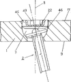
Fig. 7 illustrates by the cutaway view according to another form of implementation of device of the present invention;
Fig. 8 illustrates the view according to another form of implementation of bone screw of the present invention.
The embodiment explanation
The bone fixed body 1 of a form of implementation according to device of the present invention shown in Figure 1 is together with the part of a bone screw 2.Bone fixed body 1 constitutes as hone lamella, and has one at shank of screw one a lateral downside 9 and a upside 11 in a side of head of screw, and wherein, downside 9 is in order to lean against on the bone during with screw-driving at hone lamella.Bone screw 2 usefulness one hole 7 is received within the bone fixed body 1, and this Kong Youyi medial axis 8 also runs through bone fixed body 1, and is provided with part 10 one recessed, that diminish towards downside 9.Recessed part 10 is made spheric, and a radius of curvature X is arranged, and leads to upside 11 with a cylindrical part with diameter D.Shown in the form of implementation according to device of the present invention in, radius of curvature X is corresponding to the radius of cylindrical part, X=D/2.That bone screw 2 comprises is one 5 concentric with the screw longitudinal axis, be anchored on a shank of screw 4 and a head of screw 3 in bone or the bone parts, and one between shank of screw 4 and head of screw 3, with screw longitudinal axis 5 concentric disc projections 6, that this projection has is one flat, at the area supported 31 of a side of shank of screw.
Fig. 2 and 3 illustrates a form of implementation according to device of the present invention, and this device is used at spinal fixation system vertical carriage 13 and base stalk screw 14 being connected together.This device comprises admittance 15 and one clamping device 25 that a base stalk screw 14, has medial axis 16, this base stalk screw have one with the concentric shank of screw 21 in the bone and the head of screw 22 of a projection of being anchored on of its screw longitudinal axis 24, this admittance head is used for vertical carriage 13 and base stalk screw are connected together, this clamping device the shape of one nut is arranged substantially and with a female thread 32 by being screwed in demountable mode with upside 18 adjacent external screw threads 31 of admitting 15, and be used for admitting 15 to fix vertical carriage 13 and base obstructs screw 14.
The head of screw 22 of projection is made spherical segment, and at this moment, the summit 29 of interception is positioned on the screw longitudinal axis 24 and forms the end of the screw head side of base stalk screw 14.In addition, on head of screw 22, do two or more surfaces 30 that are parallel to screw longitudinal axis 24 orientations,, be used for base being obstructed screw 14 and be screwed into bone with screwdriver with as two outward flanges (Aussenzweikant).Also can replace two outward flanges with outer-hexagonal.
Admit 15 have a upside 18 in a side of head of screw, a downside 19 in a side of shank of screw, one with admit running through of medial axis 16 coaxial lines 15 through hole 17 and one additional perpendicular to medial axis 16 extensions, towards the passage 20 of upside 18 openings, this through hole 17 is used to admit base stalk screw 14, and this passage 20 is used to admit a vertical carriage 13.Adopt this mode, vertically carriage 13 can be put into the passage 20 of opening and can fix removably at this usefulness clamping device 25 from upside 18.
Through hole 17 comprises a recessed part 26 that diminishes towards downside 19, makes the layer shape of intercepting ball in the form of implementation according to device of the present invention of this part shown in herein.
In addition, base stalk screw 14 has one and screw longitudinal axis 24 concentric dish type projections 23 between the head of screw 22 of projection and shank of screw 21, the size of this projection is so definite, so that projection 23 can lean against on the wall 27 of through hole 17 with the different angles between screw longitudinal axis 24 and the medial axis 16 in the recessed portion 26 of through hole 17.
Form of implementation according to two-piece type bone screw 2 of the present invention shown in Figure 4.The awl that is connected between head of screw 3 and the shank of screw 4 is connected.On head of screw 3, make a taper tenon with one heart with screw longitudinal axis 5, this tenon can in one 5 concentric, as to have an inner cone 34 hole 33, be fixed on the screw longitudinal axis shank of screw 4 on the end of the first side of screw.
Fig. 5 illustrates another form of implementation according to two-piece type bone screw 2 of the present invention.Herein, being connected between head of screw 3 and the shank of screw 4 one is threaded.On head of screw 3, made a threaded tenon 35 with one heart with screw longitudinal axis 5, this tenon can in one 5 concentric, as to have female thread 37 hole 36, be screwed in the screw longitudinal axis shank of screw 4 on the end of the side of head of screw.
Fig. 6 illustrates the another form of implementation according to two-piece type bone screw 2 of the present invention.Herein, being connected between head of screw 3 and the shank of screw 4 one inserted rotating the connection.On head of screw 3, make a tenon 38 with a radially outstanding pin 39 with one heart with screw longitudinal axis 5, in the hole 40 that this pin can buckle into is one 5 concentric with the screw longitudinal axis, have a groove 43, wherein, groove 43 has one to be parallel to a part 42 and the part 41 along circumferential extension in hole 40 that screw longitudinal axis 5 extends.
Fig. 7 illustrates a form of implementation according to device of the present invention, this device and device difference shown in Figure 1 only are, fixed body 1 is one to have the hone lamella that at least one is used for the hole of running through 7 of bone screw 2, device comprises that in addition one has the holding screw 45 of the measure 47 that is used to admit a screwdriver, this holding screw can be screwed into one from the female thread 46 that upside 11 is introduced the hole 7, and presses to head of screw 22 when tightening.Adopt this holding screw that can tighten securely 45, can in hone lamella 1, obtain stable the fixing of angle of bone screw 2.
A form of implementation according to bone screw 2 of the present invention shown in Figure 8, the difference of the form of implementation shown in this bone screw and Fig. 4 to 6 only is, projection 6 comprises the edge 53,54,56 of a plurality of circles in a side of shank of screw, wherein, and diameter d, the d at these edges 53,54,56
1, d
2Size so definite so that edge 53,54,56 along one imaginary, on a side raised surface 55 of shank of screw, extend, that make on this surface is 5 concentric with medial axis, have the spherical region of radius Y.
Claims (35)
1. bone screw (2,14), it has one concentric and be anchored on a shank of screw (4,21) and a head of screw (3,22) in bone or the bone parts with screw longitudinal axis (5,24), wherein, bone screw (2,14) between head of screw (3,22) and shank of screw (4,21), have one with the concentric dish type projection of screw longitudinal axis (5,24) (6,23), the diameter of this dish type projection is greater than the diameter of shank of screw (4,21), wherein, projection (6,23) comprises a plurality of and the concentric edge of screw longitudinal axis (5,24) (53,54,56), it is characterized by
(A) edge (53,54,56) are done circular and diameter d, d are arranged
1, d
2, d
i, the size of this diameter is so definite so that the edge one imaginary, go up in a side raised surface (55) of shank of screw and to extend, and
(B) imaginary surface (55) be one concentric with medial axis (8,16), have the spherical region of radius Y.
2. bone screw as claimed in claim 1 (2,14) is characterized by, and projection (6,23) has three and the concentric edge of screw longitudinal axis (5,24) (53,54,56).
3. bone screw as claimed in claim 2 (2,14) is characterized by, and there is the diameter d>d that reduces towards shank of screw (4) at the concentric edge (53,54,56) of projection (6,23)
1>d
2>d
i
4. as each bone screw (2) of claim 1 to 3, it is characterized by, head of screw (22) is made projection.
5. bone screw as claimed in claim 4 (2) is characterized by, and head of screw (22) is made spheric.
6. bone screw as claimed in claim 5 (2) is characterized by, and head of screw (22) is made hemispheric, and wherein, intersect in end and screw longitudinal axis (24) at the top of head of screw (22).
7. as the bone screw (2) of claim 1 or 2, it is characterized by, head of screw (3,22) is made one with shank of screw (4,21).
8. as the bone screw (2) of claim 1 or 2, it is characterized by, bone screw is many, wherein, at least head of screw (3,22) and shank of screw (4,21) be separate, but be the independent part that can be connected with one heart with screw longitudinal axis (5,24).
9. bone screw as claimed in claim 8 (2) is characterized by, and head of screw (3,22) is the independent part that removably is connected with shank of screw (4,21).
10. bone screw as claimed in claim 8 (2) is characterized by, head of screw (3,22), projection (6,23) and shank of screw (4,21) be separately, but be the independent part that can be connected with one heart with screw longitudinal axis (5,24).
11. bone screw as claimed in claim 8 (2) is characterized by, head of screw (3,22) connects with an awl and is connected with shank of screw (4,21).
12. bone screw as claimed in claim 8 (2) is characterized by, head of screw (3,22) is threaded with one and is connected with shank of screw (4,21).
13. bone screw as claimed in claim 8 (2) is characterized by, head of screw (3,22) is inserted rotating connection with one and is connected with shank of screw (4,21).
14. the bone screw (2) as claim 1 or 2 is characterized by, the diameter d of projection (6,23) is 8~10mm.
15. the bone screw (2) as claim 1 or 2 is characterized by, projection (6,23) has the thickness of one 1~2mm.
16. the bone screw (2) as claim 1 or 2 is characterized by, the external diameter of shank of screw (4,21) is 5~6mm.
17. the bone screw (2) as claim 1 or 2 is characterized by, the diameter d of projection (6,23) is 4~6mm.
18. the bone screw (2) as claim 17 is characterized by, projection (6,23) has the thickness of one 0.5~1mm.
19. the bone screw (2) as claim 18 is characterized by, the external diameter of shank of screw (4,21) is 3~5mm.
20. the bone screw (2) as claim 1 or 2 is characterized by, this screw is used for engaging fixture fixing bone or bone parts at bone.
21. the bone screw (2) as claim 20 is characterized by, this screw is used for going up bone at a hone lamella (1) and decides bone or bone parts.
22. the bone screw (2) as claim 20 is characterized by, this screw is a base stalk screw (14) and is used in the fixing vertebral bodies of spinal fixation system.
23. be used for the bone stationary device that bone engages, it have at least one as claim 1 to 22 each bone screw (2,14) and
(A) at least one plate shape, prismatic or columniform fixed body (1,15), this fixed body has at least one to have medial axis (8,16), the hole (7,17) to be used to admit bone screw (2,14), with a downside in shank of screw one side (9,19) and a upside in the first side of screw (11,18), wherein
(B) hole (7,17) comprise the part that one day, downside diminished (10,26),
It is characterized by,
(C) diameter d of projection (6,23) will so be determined size, so that projection (6,23) can lean against on the wall (12,27) of hole (7,17) with the different angles between screw longitudinal axis (5,24) and the medial axis (8,16) in the recessed portion (10,26) of hole (7,17).
24. the device as claim 23 is characterized by,
(A) bone screw (2) is the base stalk screw (14) of lobed head of screw (22);
(B) fixed body (1) is one to have the admittance head (15) of medial axis (16), it is used for vertical carriage (13) and base stalk screw (14) are connected together, and this admit head (15) also have in addition one that extend perpendicular to medial axis (16), towards the passage (20) of upside (18) opening, to be used to admit vertical carriage (13); And
(C) device comprises a clamping device (25) in addition, and it can be connected with admitting head (15) from upside (18) removably, and is used for admitting head (15) to fix a vertical carriage (13) and base stalk screw (14).
25. the device as claim 23 or 24 is characterized by, disc projection (6,23) has a diameter d, and recessed part (10,26) is done globulate and a diameter D is arranged, wherein, and D=d.
26. the device as claim 23 or 24 is characterized by, disc projection (6,23) has a diameter d, and recessed part (10,26) is done globulate and a diameter D is arranged, wherein, and D>d.
27. the device as claim 26 is characterized by, d: the ratio of D is between 0.5 and 1.0.
28. the device as claim 27 is characterized by, d: the ratio of D is between 0.85 and 0.95.
29. the device as claim 23 or 24 is characterized by, recessed part (10,26) is made the layer shape of intercepting ball, and wherein, the ball layer has a radius X, and X 〉=D/2.
30. the device as claim 29 is characterized by, the ratio of D/2 and X is between 0.5 and 1.0.
31. the device as claim 30 is characterized by, the ratio of D/2 and X is between 0.85 and 0.95.
32. the device as claim 23 or 24 is characterized by, corner angle are made at the edge of projection (6,23), and at least one lower edge (28,53,54,56) arranged.
33. the device as claim 23 or 24 is characterized by, projection (6) comprises a plurality of and the concentric edge of screw longitudinal axis (5,24) (53,54,56), and they have the diameter d>d that reduces towards shank of screw (4)
1>d
2
34. device as claim 33, it is characterized by, edge (53,54,56) can lean against on the wall (12,27) of hole (7,17) with the different angles between screw longitudinal axis (5,24) and the medial axis (8,16) in the recessed portion (10,26) of hole (7,17).
35. device as claim 23 or 25, it is characterized by, fixed body (1) is a hone lamella, this plate has at least one hole of running through (7) that is used for bone screw (2), device comprises a holding screw (45) in addition, this screw has the measure that is used to admit a screwdriver, and this holding screw can be screwed into from upside (11) is introduced female thread (46) the hole (7), and is pressed against when tightening on the head of screw (22).
Applications Claiming Priority (1)
| Application Number | Priority Date | Filing Date | Title |
|---|---|---|---|
| PCT/CH1999/000302 WO2001003591A1 (en) | 1999-07-07 | 1999-07-07 | Angle-adjustable bone screw and device for the osteosynthetic bone fixation |
Publications (2)
| Publication Number | Publication Date |
|---|---|
| CN1352540A CN1352540A (en) | 2002-06-05 |
| CN1154443C true CN1154443C (en) | 2004-06-23 |
Family
ID=4551697
Family Applications (1)
| Application Number | Title | Priority Date | Filing Date |
|---|---|---|---|
| CNB998167479A Expired - Fee Related CN1154443C (en) | 1999-07-07 | 1999-07-07 | Angle-adjustable bone screw and device for the osteosynthetic bone fixation |
Country Status (15)
| Country | Link |
|---|---|
| US (1) | US6893443B2 (en) |
| EP (1) | EP1191890B1 (en) |
| JP (1) | JP4174069B2 (en) |
| KR (1) | KR100623264B1 (en) |
| CN (1) | CN1154443C (en) |
| AT (1) | ATE290826T1 (en) |
| AU (1) | AU752211B2 (en) |
| CA (1) | CA2375533C (en) |
| DE (1) | DE59911776D1 (en) |
| DK (1) | DK1191890T3 (en) |
| ES (1) | ES2238835T3 (en) |
| HK (1) | HK1042031B (en) |
| PT (1) | PT1191890E (en) |
| TW (1) | TW504377B (en) |
| WO (1) | WO2001003591A1 (en) |
Families Citing this family (74)
| Publication number | Priority date | Publication date | Assignee | Title |
|---|---|---|---|---|
| US6893444B2 (en) * | 2000-02-01 | 2005-05-17 | Hand Innovations, Llc | Bone fracture fixation systems with both multidirectional and unidirectional stabilization pegs |
| WO2003041601A1 (en) * | 2001-11-14 | 2003-05-22 | Synthes Ag Chur | Device for joining a longitudinal support with a bone fixation means |
| AU2003233587B2 (en) * | 2002-05-21 | 2008-12-18 | Warsaw Orthopedic, Inc. | Vertebrae bone anchor and cable for coupling it to a rod |
| US7001389B1 (en) | 2002-07-05 | 2006-02-21 | Navarro Richard R | Fixed and variable locking fixation assembly |
| US7780664B2 (en) | 2002-12-10 | 2010-08-24 | Depuy Products, Inc. | Endosteal nail |
| US7377923B2 (en) | 2003-05-22 | 2008-05-27 | Alphatec Spine, Inc. | Variable angle spinal screw assembly |
| US7951176B2 (en) | 2003-05-30 | 2011-05-31 | Synthes Usa, Llc | Bone plate |
| US11259851B2 (en) | 2003-08-26 | 2022-03-01 | DePuy Synthes Products, Inc. | Bone plate |
| DE20321151U1 (en) | 2003-08-26 | 2006-09-07 | Synthes Gmbh | bone plate |
| US20050059970A1 (en) * | 2003-09-17 | 2005-03-17 | Eric Kolb | Bone fixation systems |
| US8105367B2 (en) | 2003-09-29 | 2012-01-31 | Smith & Nephew, Inc. | Bone plate and bone plate assemblies including polyaxial fasteners |
| US8574268B2 (en) | 2004-01-26 | 2013-11-05 | DePuy Synthes Product, LLC | Highly-versatile variable-angle bone plate system |
| US7637928B2 (en) * | 2004-01-26 | 2009-12-29 | Synthes Usa, Llc | Variable angle locked bone fixation system |
| US11291484B2 (en) | 2004-01-26 | 2022-04-05 | DePuy Synthes Products, Inc. | Highly-versatile variable-angle bone plate system |
| US7214227B2 (en) * | 2004-03-22 | 2007-05-08 | Innovative Spinal Technologies | Closure member for a medical implant device |
| US20050216027A1 (en) * | 2004-03-24 | 2005-09-29 | Suh Sean S | Extraction screwdriver |
| US8475495B2 (en) | 2004-04-08 | 2013-07-02 | Globus Medical | Polyaxial screw |
| US7503924B2 (en) * | 2004-04-08 | 2009-03-17 | Globus Medical, Inc. | Polyaxial screw |
| US20070162023A1 (en) * | 2005-07-15 | 2007-07-12 | Schock Charles C | Washer for pedicle screw |
| JP4609218B2 (en) * | 2005-07-19 | 2011-01-12 | 富士ゼロックス株式会社 | Image forming apparatus, control method thereof, and program |
| CN101272743B (en) | 2005-07-25 | 2011-01-26 | 史密夫和内修有限公司 | Polyaxial fastener systems |
| US8382807B2 (en) | 2005-07-25 | 2013-02-26 | Smith & Nephew, Inc. | Systems and methods for using polyaxial plates |
| KR100656186B1 (en) | 2005-08-31 | 2006-12-13 | 주식회사 솔고 바이오메디칼 | Poly compressive fixation system |
| US7905909B2 (en) * | 2005-09-19 | 2011-03-15 | Depuy Products, Inc. | Bone stabilization system including multi-directional threaded fixation element |
| JP2009512465A (en) * | 2005-09-30 | 2009-03-26 | パラダイム・スパイン・リミテッド・ライアビリティ・カンパニー | Hinge multi-axis screw and method of using the same |
| US7927359B2 (en) | 2005-10-06 | 2011-04-19 | Paradigm Spine, Llc | Polyaxial screw |
| KR101246113B1 (en) * | 2005-10-25 | 2013-03-20 | 앤썸 오르소패딕스, 엘엘씨 | Bone fastening assembly and bushing and screw for use therewith |
| US8100952B2 (en) * | 2005-12-22 | 2012-01-24 | Anthem Orthopaedics Llc | Drug delivering bone plate and method and targeting device for use therewith |
| US20070233069A1 (en) * | 2006-02-27 | 2007-10-04 | Stewart Young | Implant/support member interconnection mechanism |
| ES2334811T3 (en) * | 2006-11-17 | 2010-03-16 | Biedermann Motech Gmbh | OSEO ANCHORAGE DEVICE. |
| US8142432B2 (en) * | 2007-02-05 | 2012-03-27 | Synthes Usa, Llc | Apparatus for repositioning portions of fractured bone and method of using same |
| US9072548B2 (en) * | 2007-06-07 | 2015-07-07 | Anthem Orthopaedics Llc | Spine repair assembly |
| CA2690786C (en) * | 2007-06-22 | 2015-12-15 | Anthem Orthopaedics Van, Llc | Intramedullary rod for pivoting a fastener |
| US20090069849A1 (en) * | 2007-09-10 | 2009-03-12 | Oh Younghoon | Dynamic screw system |
| WO2009114014A1 (en) * | 2008-03-13 | 2009-09-17 | Innovative Delta Technology Llc | Locking cervical screw and methods of use thereof |
| US8790343B2 (en) * | 2008-10-11 | 2014-07-29 | Epix Orthopaedics, Inc. | Intramedullary rod with pivotable and fixed fasteners and method for using same |
| US8696717B2 (en) * | 2008-11-05 | 2014-04-15 | K2M, Inc. | Multi-planar, taper lock screw with additional lock |
| US8377101B2 (en) * | 2008-11-05 | 2013-02-19 | K2M, Inc. | Multi-planar taper lock screw with increased rod friction |
| WO2010111350A1 (en) | 2009-03-24 | 2010-09-30 | Stabiliz Orthopedics, LLC | Orthopedic fixation device with bioresorbable layer |
| RU2012108851A (en) * | 2009-09-14 | 2013-10-27 | Зинтес Гмбх | VARIABLE ANGLE COMPRESSION PLATE |
| US10390867B2 (en) | 2009-09-18 | 2019-08-27 | Biomet C.V. | Bone plate system and method |
| CN102630155B (en) | 2009-09-18 | 2015-11-25 | 拜欧米特公司 | Disposable shaping surgery kit and parts |
| US8486116B2 (en) * | 2010-01-08 | 2013-07-16 | Biomet Manufacturing Ring Corporation | Variable angle locking screw |
| US8728129B2 (en) | 2011-01-07 | 2014-05-20 | Biomet Manufacturing, Llc | Variable angled locking screw |
| EP2709551B1 (en) | 2011-05-19 | 2021-04-28 | Synthes GmbH | Articulating cranial bolt |
| US9131962B2 (en) | 2011-05-24 | 2015-09-15 | Globus Medical, Inc. | Bone screw assembly |
| CA2839423A1 (en) | 2011-06-15 | 2012-12-20 | Smith & Nephew, Inc. | Variable angle locking implant |
| US9993269B2 (en) | 2011-07-15 | 2018-06-12 | Globus Medical, Inc. | Orthopedic fixation devices and methods of installation thereof |
| US9358047B2 (en) | 2011-07-15 | 2016-06-07 | Globus Medical, Inc. | Orthopedic fixation devices and methods of installation thereof |
| US9186187B2 (en) | 2011-07-15 | 2015-11-17 | Globus Medical, Inc. | Orthopedic fixation devices and methods of installation thereof |
| US9198694B2 (en) | 2011-07-15 | 2015-12-01 | Globus Medical, Inc. | Orthopedic fixation devices and methods of installation thereof |
| US8888827B2 (en) | 2011-07-15 | 2014-11-18 | Globus Medical, Inc. | Orthopedic fixation devices and methods of installation thereof |
| CN104411259B (en) | 2012-02-08 | 2017-06-13 | Epix整形外科股份有限公司 | The implant insertion apparatus of the aiming component with continuously adjustable |
| US10292832B2 (en) | 2013-03-14 | 2019-05-21 | Ohio State Innovation Foundation | Spinal fixation device |
| US9707096B2 (en) | 2013-03-14 | 2017-07-18 | K2M, Inc. | Spinal fixation device |
| US20140277155A1 (en) | 2013-03-14 | 2014-09-18 | K2M, Inc. | Taper lock hook |
| US10123828B2 (en) | 2013-03-15 | 2018-11-13 | Epix Orthopaedics, Inc. | Implantable device with pivotable fastener and self-adjusting set screw |
| US9814503B1 (en) | 2014-04-14 | 2017-11-14 | Avanti Orthopaedics, LLC | Load sharing bone plate |
| US10517657B1 (en) | 2014-04-14 | 2019-12-31 | Avanti Orthopaedics, LLC | Load sharing bone plate |
| US11452553B1 (en) | 2014-04-14 | 2022-09-27 | Avanti Orthopaedics, LLC | Load sharing bone plate |
| US11937858B2 (en) | 2014-04-14 | 2024-03-26 | Avanti Orthopaedics, LLC | Load sharing bone plate |
| US10058362B2 (en) | 2015-05-22 | 2018-08-28 | Gramercy Extremity Orthopedics Llc | Orthopedic bone fixation assembly |
| US10993750B2 (en) | 2015-09-18 | 2021-05-04 | Smith & Nephew, Inc. | Bone plate |
| WO2017049268A1 (en) | 2015-09-18 | 2017-03-23 | K2M, Inc. | Corpectomy device and method of use thereof |
| CN106037996B (en) * | 2016-07-08 | 2019-02-26 | 北京大学人民医院 | Acetabular defects rebuild prosthese |
| US10905476B2 (en) | 2016-09-08 | 2021-02-02 | DePuy Synthes Products, Inc. | Variable angle bone plate |
| US10624686B2 (en) | 2016-09-08 | 2020-04-21 | DePuy Synthes Products, Inc. | Variable angel bone plate |
| US10820930B2 (en) | 2016-09-08 | 2020-11-03 | DePuy Synthes Products, Inc. | Variable angle bone plate |
| US20180271505A1 (en) | 2017-03-23 | 2018-09-27 | Ethicon, Inc. | Scaffolds for Joining Layers of Tissue at Discrete Points |
| US11026727B2 (en) | 2018-03-20 | 2021-06-08 | DePuy Synthes Products, Inc. | Bone plate with form-fitting variable-angle locking hole |
| US10772665B2 (en) | 2018-03-29 | 2020-09-15 | DePuy Synthes Products, Inc. | Locking structures for affixing bone anchors to a bone plate, and related systems and methods |
| US11013541B2 (en) | 2018-04-30 | 2021-05-25 | DePuy Synthes Products, Inc. | Threaded locking structures for affixing bone anchors to a bone plate, and related systems and methods |
| US10925651B2 (en) | 2018-12-21 | 2021-02-23 | DePuy Synthes Products, Inc. | Implant having locking holes with collection cavity for shavings |
| TWI680036B (en) * | 2019-04-19 | 2019-12-21 | 朝友工業股份有限公司 | Positioning device with adjustable holding surface |
Family Cites Families (50)
| Publication number | Priority date | Publication date | Assignee | Title |
|---|---|---|---|---|
| NL7709897A (en) | 1977-09-08 | 1979-03-12 | Tno | EXTERNAL FIXATOR FOR BONES. |
| GB2173104B (en) | 1984-02-28 | 1987-11-25 | Peter John Webb | Spinal fixation apparatus |
| US4653481A (en) | 1985-07-24 | 1987-03-31 | Howland Robert S | Advanced spine fixation system and method |
| DE3800052A1 (en) | 1987-07-08 | 1989-07-13 | Harms Juergen | POSITIONING SCREW |
| US4790297A (en) | 1987-07-24 | 1988-12-13 | Biotechnology, Inc. | Spinal fixation method and system |
| US4887596A (en) | 1988-03-02 | 1989-12-19 | Synthes (U.S.A.) | Open backed pedicle screw |
| DE3823737A1 (en) | 1988-07-13 | 1990-01-18 | Lutz Biedermann | CORRECTION AND HOLDING DEVICE, ESPECIALLY FOR THE SPINE |
| FR2642643B1 (en) | 1989-02-09 | 1991-05-10 | Vignaud Jean Louis | SPINAL INSTRUMENTATION FOR UNIVERSAL PEDICULAR FIXATION WITH MICROMETRIC ADJUSTMENT DIAPASON SCREW |
| CH678803A5 (en) | 1989-07-12 | 1991-11-15 | Sulzer Ag | |
| DE3923996A1 (en) | 1989-07-20 | 1991-01-31 | Lutz Biedermann | RECORDING PART FOR JOINTLY CONNECTING TO A SCREW FOR MAKING A PEDICLE SCREW |
| DE3936702C2 (en) | 1989-11-03 | 1994-07-28 | Lutz Biedermann | Pedicle screw and correction and holding device with such a pedicle screw |
| CA2035348C (en) | 1990-02-08 | 2000-05-16 | Jean-Louis Vignaud | Adjustable fastening device with spinal osteosynthesis rods |
| FR2658413B1 (en) | 1990-02-19 | 1997-01-03 | Sofamor | OSTEOSYNTHESIS DEVICE FOR THE CORRECTION OF SPINAL DEVIATIONS. |
| FR2658414B1 (en) | 1990-02-19 | 1992-07-31 | Sofamor | IMPLANT FOR OSTEOSYNTHESIS DEVICE IN PARTICULAR OF THE RACHIS. |
| WO1991016020A1 (en) | 1990-04-26 | 1991-10-31 | Danninger Medical Technology, Inc. | Transpedicular screw system and method of use |
| GB9014817D0 (en) | 1990-07-04 | 1990-08-22 | Mehdian Seyed M H | Improvements in or relating to apparatus for use in the treatment of spinal disorders |
| US5129900B1 (en) | 1990-07-24 | 1998-12-29 | Acromed Corp | Spinal column retaining method and apparatus |
| CH681853A5 (en) | 1990-08-21 | 1993-06-15 | Synthes Ag | |
| CH685850A5 (en) | 1990-11-26 | 1995-10-31 | Synthes Ag | anchoring device |
| FR2672202B1 (en) * | 1991-02-05 | 1993-07-30 | Safir | BONE SURGICAL IMPLANT, ESPECIALLY FOR INTERVERTEBRAL STABILIZER. |
| US5176678A (en) | 1991-03-14 | 1993-01-05 | Tsou Paul M | Orthopaedic device with angularly adjustable anchor attachments to the vertebrae |
| DE9104025U1 (en) * | 1991-04-03 | 1992-07-30 | Waldemar Link Gmbh & Co, 2000 Hamburg, De | |
| FR2676354B1 (en) | 1991-05-17 | 1997-11-07 | Vignaud Jean Louis | LOCKABLE CONNECTION DEVICE OF SPINAL OSTEOSYNTHESIS ANCHORING ELEMENTS. |
| FR2680461B1 (en) | 1991-08-19 | 1993-11-26 | Fabrication Mat Orthopedique | IMPLANT FOR OSTEOSYNTHESIS DEVICE, ESPECIALLY OF THE RACHIS, AND CORRESPONDING DEVICE FOR ITS PLACEMENT. |
| US5257993A (en) | 1991-10-04 | 1993-11-02 | Acromed Corporation | Top-entry rod retainer |
| US5306275A (en) | 1992-12-31 | 1994-04-26 | Bryan Donald W | Lumbar spine fixation apparatus and method |
| US5364399A (en) * | 1993-02-05 | 1994-11-15 | Danek Medical, Inc. | Anterior cervical plating system |
| US5423818A (en) | 1993-02-17 | 1995-06-13 | Danek Medical, Inc. | Clamp for attaching a vertebral fixation element to a spinal rod |
| DE4307576C1 (en) | 1993-03-10 | 1994-04-21 | Biedermann Motech Gmbh | Bone screw esp. for spinal column correction - has U=shaped holder section for receiving straight or bent rod |
| FR2705226B1 (en) | 1993-05-17 | 1995-07-07 | Tornier Sa | Spine fixator to maintain a spine. |
| EP0786964B1 (en) | 1993-11-19 | 2004-03-31 | Cross Medical Products, Inc. | Rod anchor seat having sliding closure member |
| US5466237A (en) | 1993-11-19 | 1995-11-14 | Cross Medical Products, Inc. | Variable locking stabilizer anchor seat and screw |
| SE9402130D0 (en) * | 1994-06-17 | 1994-06-17 | Sven Olerud | Device and method for plate fixation of legs |
| JP3090588B2 (en) * | 1995-05-12 | 2000-09-25 | 株式会社ソミック石川 | Ball joint |
| US5562663A (en) | 1995-06-07 | 1996-10-08 | Danek Medical, Inc. | Implant interconnection mechanism |
| US5733285A (en) | 1995-07-13 | 1998-03-31 | Fastenetix, Llc | Polyaxial locking mechanism |
| US5549608A (en) | 1995-07-13 | 1996-08-27 | Fastenetix, L.L.C. | Advanced polyaxial locking screw and coupling element device for use with rod fixation apparatus |
| US5584834A (en) | 1995-07-13 | 1996-12-17 | Fastenetix, L.L.C. | Polyaxial locking screw and coupling element assembly for use with side loading rod fixation apparatus |
| US5609593A (en) | 1995-07-13 | 1997-03-11 | Fastenetix, Llc | Advanced polyaxial locking hook and coupling element device for use with top loading rod fixation devices |
| US5554157A (en) | 1995-07-13 | 1996-09-10 | Fastenetix, L.L.C. | Rod securing polyaxial locking screw and coupling element assembly |
| US5586984A (en) | 1995-07-13 | 1996-12-24 | Fastenetix, L.L.C. | Polyaxial locking screw and coupling element assembly for use with rod fixation apparatus |
| US5609594A (en) | 1995-07-13 | 1997-03-11 | Fastenetix Llc | Extending hook and polyaxial coupling element device for use with side loading road fixation devices |
| US5578033A (en) | 1995-07-13 | 1996-11-26 | Fastenetix, L.L.C. | Advanced polyaxial locking hook and coupling element device for use with side loading rod fixation devices |
| US5575792A (en) | 1995-07-14 | 1996-11-19 | Fastenetix, L.L.C. | Extending hook and polyaxial coupling element device for use with top loading rod fixation devices |
| US5782833A (en) * | 1996-12-20 | 1998-07-21 | Haider; Thomas T. | Pedicle screw system for osteosynthesis |
| ATE309752T1 (en) * | 1997-02-11 | 2005-12-15 | Michelson Gary K | SYSTEM FOR ANTERIOR PLATING OF THE CERVICAL SPINE |
| WO1998041160A1 (en) * | 1997-03-17 | 1998-09-24 | Intellect Medical Limited | Cervical fixation system |
| US5891145A (en) * | 1997-07-14 | 1999-04-06 | Sdgi Holdings, Inc. | Multi-axial screw |
| EP0933065A1 (en) * | 1998-02-02 | 1999-08-04 | Sulzer Orthopädie AG | Pivotable attachment system for a bone screw |
| EP1624931B1 (en) | 2003-05-09 | 2009-02-18 | Philips Intellectual Property & Standards GmbH | Tanning device using semiconductor light-emitting diodes |
-
1999
- 1999-07-07 EP EP99926226A patent/EP1191890B1/en not_active Expired - Lifetime
- 1999-07-07 PT PT99926226T patent/PT1191890E/en unknown
- 1999-07-07 DK DK99926226T patent/DK1191890T3/en active
- 1999-07-07 WO PCT/CH1999/000302 patent/WO2001003591A1/en active IP Right Grant
- 1999-07-07 KR KR1020027000159A patent/KR100623264B1/en not_active IP Right Cessation
- 1999-07-07 CN CNB998167479A patent/CN1154443C/en not_active Expired - Fee Related
- 1999-07-07 CA CA002375533A patent/CA2375533C/en not_active Expired - Fee Related
- 1999-07-07 DE DE59911776T patent/DE59911776D1/en not_active Expired - Lifetime
- 1999-07-07 ES ES99926226T patent/ES2238835T3/en not_active Expired - Lifetime
- 1999-07-07 AT AT99926226T patent/ATE290826T1/en not_active IP Right Cessation
- 1999-07-07 JP JP2001508880A patent/JP4174069B2/en not_active Expired - Lifetime
- 1999-07-07 AU AU43572/99A patent/AU752211B2/en not_active Ceased
-
2000
- 2000-07-06 TW TW089113373A patent/TW504377B/en not_active IP Right Cessation
-
2002
- 2002-01-07 US US10/036,531 patent/US6893443B2/en not_active Expired - Lifetime
- 2002-05-28 HK HK02103950.0A patent/HK1042031B/en not_active IP Right Cessation
Also Published As
| Publication number | Publication date |
|---|---|
| JP4174069B2 (en) | 2008-10-29 |
| AU752211B2 (en) | 2002-09-12 |
| KR100623264B1 (en) | 2006-09-18 |
| CN1352540A (en) | 2002-06-05 |
| WO2001003591A1 (en) | 2001-01-18 |
| US6893443B2 (en) | 2005-05-17 |
| DK1191890T3 (en) | 2005-06-06 |
| ES2238835T3 (en) | 2005-09-01 |
| EP1191890A1 (en) | 2002-04-03 |
| PT1191890E (en) | 2005-07-29 |
| EP1191890B1 (en) | 2005-03-16 |
| HK1042031A1 (en) | 2002-08-02 |
| ATE290826T1 (en) | 2005-04-15 |
| CA2375533C (en) | 2009-09-22 |
| US20030036758A1 (en) | 2003-02-20 |
| AU4357299A (en) | 2001-01-30 |
| DE59911776D1 (en) | 2005-04-21 |
| JP2003504105A (en) | 2003-02-04 |
| CA2375533A1 (en) | 2001-01-18 |
| KR20020027469A (en) | 2002-04-13 |
| TW504377B (en) | 2002-10-01 |
| HK1042031B (en) | 2005-05-06 |
Similar Documents
| Publication | Publication Date | Title |
|---|---|---|
| CN1154443C (en) | Angle-adjustable bone screw and device for the osteosynthetic bone fixation | |
| AU761056B2 (en) | Bone screw with axially two-part screw head | |
| US7794482B2 (en) | Device for osteosynthesis | |
| AU2002213261B2 (en) | Connector for spinal rod and vertebral anchor | |
| CN1146365C (en) | Device for connecting longitudinal support with pedicle screw | |
| CN1192749C (en) | Multi-axial bone screw assembly | |
| CN101347351B (en) | Bone anchoring device | |
| US7104992B2 (en) | Spinal fixation system | |
| US7935135B2 (en) | Spinal fixation device | |
| US5910142A (en) | Polyaxial pedicle screw having a rod clamping split ferrule coupling element | |
| CN1965769A (en) | Bone anchoring device | |
| CN1505492A (en) | Spinal osteosynthesis device and preparation method | |
| CN1142746C (en) | Device for connecting longitudinal support to pedicle screw | |
| CN1255082C (en) | Vertebral alignment and fixation assembly | |
| CN1835717A (en) | Device for fixing longitudinal carrier to bone fixing element | |
| CA2669794C (en) | Angle-adjustable bone screw and device for the osteosynthetic bone fixation | |
| NZ515763A (en) | Angle-adjustable bone screw and device for the osteosynthetic bone fixation | |
| ZA200109471B (en) | Angle-adjustable bone screw and device for the osteosynthetic bone fixation. | |
| WO2005018470A1 (en) | Low profile vertebral alignment and fixation assembly | |
| ZA200404242B (en) | Device for performing osteosynthesis. |
Legal Events
| Date | Code | Title | Description |
|---|---|---|---|
| C06 | Publication | ||
| PB01 | Publication | ||
| C10 | Entry into substantive examination | ||
| SE01 | Entry into force of request for substantive examination | ||
| C14 | Grant of patent or utility model | ||
| GR01 | Patent grant | ||
| ASS | Succession or assignment of patent right |
Owner name: SYNTHES LTD. Free format text: FORMER OWNER: SYNTHES AG CHUR Effective date: 20061201 |
|
| C41 | Transfer of patent application or patent right or utility model | ||
| TR01 | Transfer of patent right |
Effective date of registration: 20061201 Address after: Swiss Obbo Dov Patentee after: Synthes AG Address before: Swiss Kurdish Patentee before: Chur Synthes AG |
|
| CF01 | Termination of patent right due to non-payment of annual fee |
Granted publication date: 20040623 Termination date: 20160707 |
|
| CF01 | Termination of patent right due to non-payment of annual fee |