CN115324685B - Centrifugal separator and engine system - Google Patents
Centrifugal separator and engine system Download PDFInfo
- Publication number
- CN115324685B CN115324685B CN202211260205.4A CN202211260205A CN115324685B CN 115324685 B CN115324685 B CN 115324685B CN 202211260205 A CN202211260205 A CN 202211260205A CN 115324685 B CN115324685 B CN 115324685B
- Authority
- CN
- China
- Prior art keywords
- oil
- discs
- centrifugal separator
- shell
- gas
- Prior art date
- Legal status (The legal status is an assumption and is not a legal conclusion. Google has not performed a legal analysis and makes no representation as to the accuracy of the status listed.)
- Active
Links
Images


Classifications
-
- F—MECHANICAL ENGINEERING; LIGHTING; HEATING; WEAPONS; BLASTING
- F01—MACHINES OR ENGINES IN GENERAL; ENGINE PLANTS IN GENERAL; STEAM ENGINES
- F01M—LUBRICATING OF MACHINES OR ENGINES IN GENERAL; LUBRICATING INTERNAL COMBUSTION ENGINES; CRANKCASE VENTILATING
- F01M13/00—Crankcase ventilating or breathing
- F01M13/04—Crankcase ventilating or breathing having means for purifying air before leaving crankcase, e.g. removing oil
- F01M2013/0422—Separating oil and gas with a centrifuge device
-
- F—MECHANICAL ENGINEERING; LIGHTING; HEATING; WEAPONS; BLASTING
- F01—MACHINES OR ENGINES IN GENERAL; ENGINE PLANTS IN GENERAL; STEAM ENGINES
- F01M—LUBRICATING OF MACHINES OR ENGINES IN GENERAL; LUBRICATING INTERNAL COMBUSTION ENGINES; CRANKCASE VENTILATING
- F01M13/00—Crankcase ventilating or breathing
- F01M13/04—Crankcase ventilating or breathing having means for purifying air before leaving crankcase, e.g. removing oil
- F01M2013/0438—Crankcase ventilating or breathing having means for purifying air before leaving crankcase, e.g. removing oil with a filter
Landscapes
- Engineering & Computer Science (AREA)
- Mechanical Engineering (AREA)
- General Engineering & Computer Science (AREA)
- Lubrication Details And Ventilation Of Internal Combustion Engines (AREA)
Abstract
The invention discloses a centrifugal separator and an engine system, the centrifugal separator includes: a housing, a stack assembly, and a first adsorbent filter. The shell is internally provided with a separation cavity, and the shell is provided with an air inlet pipe, an air outlet pipe and an output port. The stacking assembly is used for separating gas and oil liquid and comprises a rotating shaft and a plurality of discs, each disc is provided with a first surface and a second surface which are opposite, and a gap for flowing an oil-gas mixture is formed between the first surface and the second surface between every two adjacent discs. The stacking assembly further comprises a first adsorption filter element which is arranged between two adjacent discs and used for separating oil liquid in the oil-gas mixture flowing through the gaps between the discs. The first adsorption filter piece among the plurality of discs filters the oil-gas mixture flowing through the gaps among the discs again, so that the oil liquid particles with small particle sizes still contained in the gas filtered by the discs are prevented from being discharged to the outside and polluting the environment.
Description
Technical Field
The invention relates to the technical field of centrifugal separation, in particular to a centrifugal separator and an engine system.
Background
When the crankcase of the engine works, engine oil in the crankcase can be discharged to the outside along with discharged gas, if the engine oil in the gas can not be separated in time and then is sent back to the crankcase, after a period of time, engine oil loss can be caused, and the engine oil directly discharged to the outside along with the gas can also pollute the environment.
The centrifugal oil-gas separator is installed in an existing engine system, discharged engine oil and gas are mixed to form an oil-gas mixture, the oil-gas mixture enters the centrifugal oil-gas separator, a rotor drives discs to rotate, the oil-gas mixture flows outwards through a gap between the two discs, oil and gas are separated under the action of centrifugal force, the separated oil is sent back to the inside of a crankcase through an oil return opening again to participate in lubrication of the crankcase, and therefore loss of the engine oil in actual work is avoided or reduced.
In order to improve the separation efficiency, the existing centrifugal oil-gas separator generally adopts a mode of improving the rotating speed of a rotor, increasing the number of discs and reducing the disc gaps to improve the oil-gas separation efficiency, the rotating speed of the existing rotor is as high as 1 ten thousand revolutions per minute, and the number of the discs is 40-50. The number of discs is increased and the disc gap is reduced, the disc gap is usually about 0.4mm, so that the cost and the volume of the centrifugal oil-gas separator are increased, the centrifugal oil-gas separator cannot be installed on part of engines, and the bearing load is overlarge.
Therefore, there is still a need for a centrifugal oil-gas separator that can maintain high separation efficiency under the premise of low rotor speed, small number of discs and large disc gap.
Disclosure of Invention
The present invention provides a centrifugal separator and an engine system that solve the above problems.
The purpose of the invention is realized by adopting the following technical scheme:
a centrifugal separator comprising: a housing, a stack assembly, and a first adsorbent filter.
The inside separation chamber that has of shell, be provided with the delivery outlet that is used for the gas mixture to get into the intake pipe in separation chamber, is used for the gas outgoing's of after-separating outlet duct and is used for the oil extraction on the shell. The stack subassembly is used for passing through centrifugal force with the oil-gas mixture who gets into from the intake pipe and separates gas and fluid to make the gas after the separation discharge from the outlet duct, make the fluid after the separation discharge from the delivery outlet, the stack subassembly includes pivot and a plurality of discs, at least a part of pivot is located in the shell, a plurality of discs are piled up along the axial of pivot and are set up and be located in the shell, the pivot is used for driving a plurality of discs are rotatory, the disc has relative first surface and second surface, adjacent two have the clearance that is used for oil-gas mixture to flow between the disc. The stack assembly further comprises a first adsorption filter, wherein the first adsorption filter is arranged between two adjacent disc sheets and is used for separating oil in oil-gas mixture flowing through gaps of the disc sheets.
Preferably, the first adsorption filter is annularly arranged on the first surface and/or the second surface of the disc, and the first adsorption filter is close to the outer edge of the disc.
Preferably, the stacking assembly further comprises an upper press shell located above the plurality of discs, and a lower press shell located below the plurality of discs, wherein an outer side edge of the upper press shell has an upper extension extending toward the lower press shell, an outer side edge of the lower press shell has a lower extension extending toward the upper press shell, the upper extension and the lower extension respectively wrap around a portion of the outer sides of the plurality of discs and are spaced apart from the plurality of discs, and a second adsorption filter is disposed on an inner side wall of the upper extension and/or the lower extension.
Preferably, the upper extension part and the lower extension part are respectively annular and are provided with a plurality of through holes penetrating from inside to outside.
Preferably, the second adsorbs and strains a piece including first connecting portion and second connecting portion, first connecting portion are arranged in connecting the video disc that is located the below in a plurality of video discs, the second connecting portion are arranged in connecting the video disc that is located the top in a plurality of video discs, the second adsorbs and strains a piece wholly for cup jointing a plurality of cover barrel-shaped structure in the video disc periphery, the second adsorbs and strains a piece and has many bars that are the annular distribution and at the axial extension of pivot, the bars are used for adsorbing the fluid through the video disc clearance.
Preferably, the outlet pipe is close to the upper end of the housing, the inlet pipe and the outlet are close to the lower end of the housing, and the throttling effect of the first adsorption filter element between two adjacent discs on the oil-gas mixture is gradually reduced in the direction from the upper end to the lower end of the housing.
Preferably, the oil filter further comprises a re-absorption filter element, the re-absorption filter element is arranged on the inner side wall of the shell, and is arranged at intervals with the outer side edges of the first adsorption filter element and the disc, and the re-absorption filter element is used for adsorbing and filtering oil flowing through the re-absorption filter element.
Preferably, first absorption is strained piece and is filtered piece with the resorption and is porous felt or porous brush, centrifugal separator includes the edge a plurality of resorption that the circumference interval of the inside wall of shell set up filters the piece, resorption filters the piece and is the strip and follows the direction of height of shell extends.
Preferably, the separating chamber still includes a plurality of water conservancy diversion muscle, and is a plurality of the water conservancy diversion muscle is divided into the multiunit, and every group is a plurality of the water conservancy diversion muscle is in be discontinuous distribution, the multiunit the water conservancy diversion muscle is followed the circumference interval distribution of the inside wall of shell, the water conservancy diversion muscle is used for gathering and guides fluid to flow downwards.
Preferably, the water conservancy diversion muscle is for following the linear form that the direction of height of the inside wall of shell extends, and is following the circumference of the inside wall of shell, adjacent two the water conservancy diversion muscle is crisscross the setting from top to bottom. Alternatively, the first and second liquid crystal display panels may be,
the water conservancy diversion muscle is circular-arc for central angle less than or equal to 90 degrees, the plumb line of the string of water conservancy diversion muscle with the direction of height of the inside wall of shell is 30-60 degrees contained angles, just the circular arc of water conservancy diversion muscle is interior week and is used for gathering oil.
Preferably, still include the plug connector, plug connector detachably peg graft in the inlet tube and/or in the outlet pipe, the plug connector has the vortex structure for the separation passes through oil in the oil-gas mixture of plug connector.
Preferably, the flow disturbing structure of the plug connector is a rotating blade.
Preferably, the separation chamber further comprises an oleophobic coating formed on the inner wall of the separation chamber, and the oleophobic coating is used for accelerating the flow of oil on the inner wall of the separation chamber.
An engine system comprises the centrifugal separator, a crankcase and an oil return pipeline, wherein an air inlet pipe of the centrifugal separator is communicated with an air outlet of the crankcase, and an output port of the centrifugal separator is communicated with the crankcase through the oil return pipeline and used for returning separated oil to the crankcase.
Compared with the prior art, the invention has the beneficial effects that at least:
the first adsorption filter element is connected to the discs of the centrifugal separator, when the stacked discs rotate along the rotating shaft, oil-gas mixture flows along the radial direction of the discs and is separated, the first adsorption filter element arranged among the discs filters and separates the oil-gas mixture flowing through gaps among the discs again, oil particles with small particle sizes still contained in gas filtered by the discs are prevented from being discharged to the outside to pollute the environment, and high separation efficiency can still be maintained on the premise that the rotor rotates at a low speed, the number of the discs is small, and the gaps among the discs are large.
Drawings
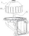
FIG. 1 is a schematic diagram of a centrifugal separator according to an embodiment of the invention;
FIG. 2 is a first partial schematic view of a centrifugal separator according to an embodiment of the invention;
FIG. 3 is a second partial schematic view of a centrifugal separator according to an embodiment of the invention;
FIG. 4 is a schematic view of a portion of a centrifugal separator according to an embodiment of the invention;
FIG. 5 is a cross-sectional view of a centrifugal separator of an embodiment of the invention;
FIG. 6 is an enlarged view of a portion of FIG. 5 at A;
FIG. 7 is a cross-sectional view of a centrifugal separator arrangement according to another embodiment of the invention;
FIG. 8 is a partial enlarged view of FIG. 7 at B;
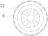
figure 9 is a top view of a disk with a first adsorptive filter according to an embodiment of the present invention.
In the figure: 1. a housing; 11. an air inlet pipe; 12. an air outlet pipe; 13. an output port; 2. stacking the components; 21. a rotating shaft; 22. a disc; 3. a second adsorption filter; 31. a first connection portion; 32. a second connecting portion; 4. pressing the shell upwards; 41. an upper extension; 5. pressing the shell downwards; 51. a lower extension; 7. A plug-in unit; 8. a first adsorbent filter.
Detailed Description
Example embodiments will now be described more fully with reference to the accompanying drawings. Example embodiments may, however, be embodied in many different forms and should not be construed as limited to the embodiments set forth herein; rather, these embodiments are provided so that this disclosure will be thorough and complete, and will fully convey the concept of example embodiments to those skilled in the art. The same reference numerals in the drawings denote the same or similar structures, and thus their repetitive description will be omitted.
The words expressing the position and direction described in the present invention are illustrated in the accompanying drawings, but may be changed as required and still be within the scope of the present invention.
Referring to fig. 1-9, the present invention provides a centrifugal separator comprising: the housing 1, the stack assembly 2, and the first adsorptive filter 8.
The inside separation chamber that has of shell 1, be provided with the intake pipe 11 that is used for oil-gas mixture to get into the separation chamber on the shell 1, be used for the gas outgoing's of after-separating outlet duct 12 and the delivery outlet 13 that is used for the oil extraction.
The stack assembly 2 is used for separating gas and oil from an oil-gas mixture entering from an air inlet pipe 11 through centrifugal force, discharging the separated gas from an air outlet pipe 12 and discharging the separated oil from an output port 13, the stack assembly 2 comprises a rotating shaft 21 and a plurality of discs 22, at least one part of the rotating shaft 21 is positioned in the shell 1, the discs 22 are stacked along the axial direction of the rotating shaft 21 and positioned in the shell 1, the rotating shaft 21 can be driven by an existing motor or oil drive, the rotating shaft 21 is used for driving the discs 22 to rotate, the discs 22 are provided with a first surface and a second surface which are opposite, and the first surface and the second surface are respectively two opposite surfaces positioned on the same disc 22. A gap for the flow of the oil-gas mixture is formed between two adjacent discs 22.
Referring to fig. 9, the stack assembly 2 further includes a first adsorption filter 8, and the first adsorption filter 8 is disposed between two adjacent discs 22 for separating oil from the oil-gas mixture flowing through the gaps between the discs 22.
In the invention, the rotating speed of the rotating shaft 21 can be 6500-7500 r/min, such as 7000 r/min, and compared with the existing rotating speed of up to 1 ten thousand r/min, the damage to the bearing can be obviously reduced and the reliability of the centrifugal separator can be obviously improved by reducing the rotating speed. The number of the discs 22 can be 15-30, preferably 20-25, compared with the number of 40-50 discs 22, the volume and the cost of the centrifugal separator can be reduced by reducing the number of the discs 22, the centrifugal separator can be assembled on more engines, and the weight of the stack of the discs 22 can be reduced by reducing the number of the discs 22, so that the damage to the bearing is reduced. The gap between the discs 22 may be 0.8-0.9mm, and the first adsorption filter 8 is conveniently disposed by increasing the gap between the discs 22 compared to the gap of the conventional discs 22 of about 0.4 mm.
Due to the increased clearance between the discs 22, the overall resistance of the stack assembly 2 to the oil-gas mixture is reduced and the oil-gas separation efficiency is reduced when the oil-gas mixture is separated. In order to make up the deficiency that the separation efficiency is reduced due to the increase of the clearance, the first adsorption filter element 8 is arranged at the clearance between the discs 22, the first adsorption filter element 8 can adsorb and filter the oil, the small liquid drops stay on the first adsorption filter element 8 and are aggregated with other small liquid drops into large liquid drops, and the large liquid drops are thrown to the inner wall of the shell 1 after being separated from the first adsorption filter element 8 under the action of centrifugal force along with the gradual increase of the weight of the large liquid drops, so that the centrifugal separator still keeps high separation efficiency. Compare the passive form first adsorption filtration piece 8 that has adsorption only set up on the inner wall of shell 1, at the during operation, fluid on the first adsorption filtration piece 8 flows downwards, and the gas after the separation flows towards the top, fluid on the first adsorption filtration piece 8 can receive the hindrance when flowing, lead to fluid can not flow down smoothly, return oil efficiency descends, and this application proposes a new design concept, set up first adsorption filtration piece 8 between video disc 22 and follow the rotation of video disc 22, first adsorption filtration piece 8 can filter fluid, first adsorption filtration piece 8 plays the filtration separation effect of an active filtration, when the oil quality on first adsorption filtration piece 8 reunites into the oil droplet of great quality, fluid will be thrown away on the inner wall from first adsorption filtration piece 8 under the effect of centrifugal force, first adsorption filtration piece 8 can not cause the influence to the oil return of fluid, return oil efficiency is higher.
When a plurality of discs 22 of the centrifugal separator rotate along a rotating shaft 21, areas with different pressure ranges are formed in the separation cavity, a gap between the discs 22 close to the rotating shaft 21 is a low-pressure area, a gap between the discs 22 far away from the rotating shaft 21 is a high-pressure area, an oil-gas mixture is conveyed into the separation cavity through an air inlet pipe 11, the oil-gas mixture flows along the gap between the discs 22 under the action of pressure difference on the discs 22, most oil is separated under the centrifugal force of the discs 22, and residual oil particles continue to flow to the edge along the gap between the discs 22 along with airflow, so that the first adsorption filter piece 8 arranged between the discs 22 can filter and separate oil in the residual oil-gas mixture again.
Preferably, the first adsorption filter 8 is annularly disposed on the first surface and/or the second surface of the disk 22, and the first adsorption filter 8 is close to the outer edge of the disk 22. The upper surface of the same disc 22 is for example a first surface, while the lower surface below is a second surface, and the first adsorption filter 8 is for example an annular felt attached to the first surface of the disc 22, or a brush with holes, which felt or brush is preferably formed directly on the disc 22 near the edge when processing the disc 22. For example, the root of the brush is located in the disc 22, the top of the brush faces upward from the disc 22, and the brush located between the upper disc 22 and the lower disc 22 can filter the oil flowing through the gap between the brushes. Alternatively, the felt or brush may be adhered to the edge of the disc 22 by adhesive after the disc 22 is processed. The ratio of the width of the first adsorbing filter 8 in the generatrix direction of the disc 22 to the width of the disc 22 in the generatrix direction may be 1: (5-20) in a ratio of, for example, 1: 8. 1:10 or 1:15; the height of the first adsorption filter 8 may be 0.1-0.6mm, for example 0.2mm, 0.3mm, 0.4mm, 0.5mm; the mean porosity of the first adsorption filter element 8 is, for example, 0.1 to 10 μm, for example 0.5 μm, 0.8 μm, 2 μm, 4 μm, 5 μm, 7 μm or 9 μm.
Preferably, the stacking assembly 2 further comprises an upper pressing shell 4 located above the plurality of discs 22, and a lower pressing shell 5 located below the plurality of discs 22, the outer edge of the upper pressing shell 4 has an upper extension 41 extending towards the lower pressing shell 5, and in fig. 2, the upper extension 41 extends to the lower pressing shell 5; in fig. 4, upper extension 41 extends to near middle disc 22. The outer edge of the lower press shell 5 has a lower extension 51 extending towards the upper press shell 4, the lower extension 51 extending to the disc 22 near the middle in fig. 3. The upper extension 41 and the lower extension 51 are respectively wrapped around a portion of the outer sides of the plurality of discs 22 and spaced apart from the plurality of discs 22, the second adsorption filter member 3 is disposed on the inner sidewall of the upper extension 41 and/or the lower extension 51, and the upper extension 41 and the lower extension 51 may not overlap in the up-down direction. Meanwhile, the upper extension part 41 and the lower extension part 51 are provided with through holes which are uniformly distributed, the upper extension part 41 and the lower extension part 51 are provided with the second adsorption filter member 3 facing the gap between the discs 22, and when the second adsorption filter member 3 connected to the upper pressure shell 4 or the lower pressure shell 5 is installed, the corresponding fixing position is close to the gap between the discs 22 along with the fact that the upper pressure shell 4 or the lower pressure shell 5 is sleeved on the rotating shaft 21.
In one embodiment, the upper extension 41 and the lower extension 51 are respectively annular and provided with a plurality of through holes penetrating inside and outside. The upper extension portion 41 and the lower extension portion 51 may be integrally formed with the corresponding upper press shell 4 and the corresponding lower press shell 5 by turning during machining, or the upper extension portion 41, the lower extension portion 51, the upper press shell 4 and the lower press shell 5 may be machined by welding, and then the upper extension portion 41 and the upper press shell 4 are welded, and the lower extension portion 51 and the lower press shell 5 are welded, which is not limited herein.
During separation, the oil-gas mixture is firstly in a gap between the discs 22 close to the rotating shaft 21, as the rotating shaft 21 drives the discs 22 to rotate, oil with large particle size in the oil-gas mixture is separated and thrown onto the inner wall of the housing 1 through the through holes of the upper extension part 41 or the lower extension part 51, the rest oil-gas mixture continues to flow to the edge of the discs 22 along the gap between the discs 22 and finally passes through the first adsorption filter part 8 and the second adsorption filter part 3 on the inner side wall of the upper extension part 41 or the lower extension part 51 from the gap of the edges of the discs 22, the oil with small particle size passes through the double filtration of the first adsorption filter part 8 on the edges of the discs 22 and the second adsorption filter part 3 on the inner side wall of the upper extension part 41 or the lower extension part 51, and is agglomerated into oil with large particle size on the first adsorption filter part 8 or the second adsorption filter part 3, when the oil on the first adsorption filter part 8 or the second adsorption filter part 3 is agglomerated more, oil drops are thrown onto the inner wall of the housing 1 and finally fall to the bottom of the corresponding separation chamber in the housing 1, and oil recovery chamber is realized. In addition, by arranging the upper extension 41 and the lower extension 51, the air-fuel mixture flowing out through the gap between the discs 22 passes through the upper extension 41 and the lower extension 51, the original flow path is changed, the air-fuel mixture cannot smoothly flow out of the centrifugal separator, the collision probability with the upper extension 41 and the lower extension 51 is increased, the upper extension 41 and the lower extension 51 also perform a separation function, and the separation efficiency is improved.
When the oil-gas mixture flows through the through holes of the upper extension 41 and the lower extension 51, the flow velocity of the gas flow is increased, and a high pressure rise can be maintained between the gas outlet pipe 12 and the gas inlet pipe 11 of the centrifugal separator.
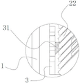
In a specific embodiment, the second adsorptive filter member 3 may also be directly connected to the disc 22, the second adsorptive filter member 3 includes a first connection portion 31 and a second connection portion 32, the first connection portion 31 is used to connect the lower disc 22 of the plurality of discs 22, the second connection portion 32 is used to connect the upper disc 22 of the plurality of discs 22, the second adsorptive filter member 3 is integrally a sleeve-shaped structure sleeved on the periphery of the plurality of discs 22, and the second adsorptive filter member 3 has a plurality of bars annularly distributed and extending in the axial direction of the rotating shaft 21, and the bars are used to adsorb and filter the oil passing through the gaps of the discs 22.
Specifically, a plurality of grid bars are annularly distributed along the circumferential direction of the second adsorption filter member 3, and each grid bar extends along the axial direction of the rotating shaft 21. The sleeve-shaped second adsorption filtration piece 3 is sleeved at the outer edge of the disc 22, wherein the first connecting part 31 and the second connecting part 32 can both be bulges extending into the gap between the disc 22 and extend into the gap between the disc 22, so that the sleeve-shaped second adsorption filtration piece 3 can be sleeved at the outer edge of the disc 22, the length is enough, and the first connecting part 31 and the second connecting part 32 are distributed in a strip shape from top to bottom, and the adsorbed oil can be guided downwards to flow into the lower part of the separation cavity, thereby being beneficial to downward conveying of the oil.
The first connecting portion 31 and the second connecting portion 32 may be chucks respectively clamped at the edge gaps of the upper disc 22 and the lower disc 22 to fix the second adsorbing and filtering member 3 in the shape of a bar at the outer edges of the plurality of discs 22, or may be hooks, and when the hooks are selected, the edge of the disc 22 is correspondingly provided with a groove for hooking. When rotatory, first connecting portion 31 and second connecting portion 32 are fixed with the second both ends of adsorbing and filtering piece 3 respectively, and when oil-gas mixture filtered piece 3 through the second adsorption, the oil liquid adhesion of part small particle diameter was adsorbed on the second adsorbed and is filtered piece 3, and when the second adsorbed when filtering the fluid on piece 3 more, the bottom that falls the separation chamber about the direction of gravity after gathering, is collected by unifying at last.
Wherein, the grid is the strip structure that forms on the second adsorbs filtering piece 3, and the material is unanimous with the material that the second adsorbs filtering piece 3, has the adsorption effect.
In one embodiment, the outlet pipe 12 is close to the upper end of the housing 1, the inlet pipe 11 and the outlet 13 are close to the lower end of the housing 1, and the throttling effect of the first adsorption filter element 8 between two adjacent discs 22 on the oil-gas mixture is gradually reduced in the direction from the upper end to the lower end of the housing 1.
When the centrifugal separator works, an oil-gas mixture enters a flow channel formed by a plurality of stacked discs 22 in one direction, the flow channel is adjacent to the rotating shaft 21 and extends along the axial direction of the rotating shaft 21, then when the discs 22 rotate, the oil-gas mixture in the flow channel flows through gaps among the discs 22 under the centrifugal action, and partial oil is separated from the discs 22 at corresponding positions. Because a plurality of flow passages are formed among a plurality of existing stacked discs 22, in the existing centrifugal separator, the cross-sectional area of each flow passage in the up-down direction is the same, when an oil-gas mixture enters the flow passages from the down direction to the up direction, the oil-gas mixture tends to enter the gaps of the upper discs 22 under the action of inertia, so that the flow rate of the oil-gas mixture between the discs 22 close to the upper direction is large, the flow rate of the oil-gas mixture between the discs 22 close to the lower direction is small, the flow rate imbalance phenomenon occurs, particularly when the gaps of the discs 22 are large, the flow rate imbalance phenomenon is more obvious, and the direct result of the flow rate imbalance is that the residence time of small liquid droplets (about 1 μm) of oil in the oil-gas mixture between the discs 22 close to the upper direction on the discs 22 is shortened, so that the small liquid droplets cannot be aggregated into large liquid droplets, the small liquid droplets are easier to be discharged out of the centrifugal oil-gas separator along with the gas, and finally the separation efficiency is reduced. Therefore, achieving flow balance is key to improving the efficiency of centrifugal separators.
In the present invention, the first adsorption filter element 8 is designed to be from top to bottom, the throttling effect of the first adsorption filter element 8 on the oil-gas mixture is gradually reduced, and the flow balance can be effectively promoted, specifically, the large throttling effect means the small flow rate of the oil-gas mixture, and the small throttling effect means the large flow rate of the oil-gas mixture, when the centrifugal separator rotates, the air flow of the oil-gas mixture flowing from bottom to top preferentially passes through the gap between the upper disc pieces 22 under the inertia effect of the air flow, and the air flow of the gap between the lower disc pieces 22 is relatively small, so that the plurality of disc pieces 22 on the rotating shaft 21 cannot be fully utilized. According to the application, the first adsorption filter piece 8 with different material densities is added among the gaps of the disc pieces 22, when the oil-gas mixture passes through the first adsorption filter piece 8, due to the fact that the densities of the first adsorption filter piece 8 are different, pressure resistance values of the oil-gas mixture after the oil-gas mixture flows out from the gaps among the disc pieces 22 at different positions are different, finally, the flow of the gaps among the disc pieces 22 in unit time is the same, and therefore the flow of the oil-gas mixture among the disc pieces 22 in the centrifugal separator is guaranteed to reach a balanced state. The efficiency of normal separation fluid of a plurality of discs 22 is guaranteed, not only can be to the fluid separation in the oil-gas mixture between the disc 22 of flowing through, can also promote balanced flow, guarantee that the inside air current of oil and gas separator is stable.
For example, the first adsorption filter 8 is arranged in the gaps between the discs 22 along the rotating shaft 21 from top to bottom, the material density of the first adsorption filter 8 in the gap between the upper discs 22 is high, the blocking capability is strong, the material density of the first adsorption filter 8 in the gap between the lower discs 22 is low, the blocking capability is weak, the flow rate of the gap between the upper discs 22 and the lower discs 22 is balanced or tends to be balanced, and the gaps between the discs 22 are fully utilized, so that the overall separation efficiency of the oil-gas separator is improved.
In other possible embodiments, the throttling effect of the first adsorption filter 8 on the mixture of oil and gas decreases from top to bottom, and can also be achieved in other ways, such as: the thickness of the first adsorption filter piece 8 in the gap between the upper disc pieces 22 is large, the thickness of the first adsorption filter piece 8 in the gap between the lower disc pieces 22 is small, and the thickness of each first adsorption filter piece 8 can be gradually reduced from top to bottom; or, the width of the first adsorption filter element 8 in the gap between the upper discs 22 is large, and the width of the first adsorption filter element 8 in the gap between the lower discs 22 is small, and the width of each first adsorption filter element 8 can be gradually reduced from top to bottom; or, the first adsorbing and filtering element 8 is a sectional structure, a gap is left between two sections, the gap between two sections of the first adsorbing and filtering element 8 located in the gap between the upper disc 22 is small, the gap between two sections of the first adsorbing and filtering element 8 located in the gap between the lower disc 22 is large, and the gap between two sections of each first adsorbing and filtering element 8 can be gradually increased from top to bottom.
The preferred centrifugal separator further comprises a re-absorption filter member disposed on the inner side wall of the housing 1 and spaced from the outer side edges of the first adsorption filter member 8 and the disk 22 for adsorbing and filtering oil flowing through the re-absorption filter member. Wherein the material of the re-absorption filter member and the material of the first absorption filter member 8 and the second absorption filter member 3 can be the same, and the re-absorption filter member is, for example, disposed on the inner side wall of the housing 1 and spaced from the first absorption filter member 8, and also spaced from the outer edge of the disc 22, the upper extension 41 and the lower extension 51. When the device works, after most oil is separated from the oil-gas mixture through the disc 22, a small amount of oil carried by the residual gas is respectively adsorbed by the first adsorption filter element 8 and the second adsorption filter element, so that the oil is fully absorbed, and the oil is prevented from being discharged to the outside to pollute the atmosphere.
It is specific, first absorption filters piece 8 and resorption and filters piece for example be porous felt or porous brush, centrifugal separator includes the edge a plurality of resorption filter pieces that the circumference interval of the inside wall of shell 1 set up, resorption filter piece is the strip and follows the direction of height of shell 1 extends, and resorption filter piece is the strip along 1 inside wall of shell and distributes, and the preferred butt of resorption filter piece of downwardly extending is in the bottom in separation chamber, and the resorption filter piece that the strip distributes is when participating in the separation work, and fluid can be earlier adsorbed in the inside of resorption filter piece, and when the inside fluid of resorption filter piece reaches the maximum adsorption capacity, at this moment, the liquid level tension of the fluid that falls on resorption filter piece surface once more is less, and fluid will slide down along the strip extending direction of resorption filter piece, and resorption filter piece has the effect of direction drainage, with the bottom of partial fluid guide flow direction separation chamber, accelerate the backward flow efficiency of fluid. Compared with the re-absorption filter piece arranged on the whole inner side wall of the shell 1, the re-absorption filter piece distributed in a strip shape not only has better filtering and separating effects, but also has less influence on the reflux efficiency.
Preferably, the separating chamber still includes a plurality of water conservancy diversion muscle (not shown), and is a plurality of the water conservancy diversion muscle is divided into the multiunit, and every group is a plurality of the water conservancy diversion muscle is in be discontinuous distribution on the direction of height of the inside wall of shell 1, the multiunit the water conservancy diversion muscle is followed the circumference interval distribution of the inside wall of shell 1, the water conservancy diversion muscle is used for gathering and guides fluid to flow downwards. The water conservancy diversion muscle forms on the inside wall of shell 1, and is protruding from the inside wall, adsorbs and is got rid of the fluid on the inside wall along the surperficial gliding of water conservancy diversion muscle through video disc 22, and the fluid particulate matter of a large amount of small particle sizes on the water conservancy diversion muscle can collect under the guide of water conservancy diversion muscle and the effect of gravity for the speed of fluid backward flow promotes centrifugal separator's separation efficiency and oil return rate.
More preferably, the water conservancy diversion muscle is for following the linear of the direction of height extension of the inside wall of shell 1, and is following the circumference of the inside wall of shell 1, adjacent two the water conservancy diversion muscle is crisscross the setting from top to bottom. The water conservancy diversion muscle on the same high projection direction of 1 inside wall of shell is discontinuous form, because fluid among the oil-gas mixture is by the after-separating, gaseous can follow the top and rise along the inner wall, and the water conservancy diversion muscle of discontinuous form is less to the resistance of fluid whereabouts, compares in from last to continuous water conservancy diversion muscle down to the resistance of fluid, can make the stable gliding and recovery of fluid.
Or, the diversion rib can also be arc-shaped with a central angle less than or equal to 90 degrees, the perpendicular bisector of the chord of the diversion rib forms an included angle of 30-60 degrees with the height direction of the inner side wall of the shell 1, and the inner circumference of the arc of the diversion rib is used for collecting oil. Get rid of and glide and collect along the direction of circular arc to some fluid on the inner wall of shell 1, because the direction of air current is by supreme down, the air current will flow towards the top along nearest route, consequently, the resistance of circular-arc water conservancy diversion muscle reduction air current that can the great degree makes fluid flow back smoothly and collects.
In one embodiment, the centrifugal separator further comprises a plug 7, the plug 7 is detachably plugged in the air inlet pipe 11 or the air outlet pipe 12, or the air inlet pipe 11 and the air outlet pipe 12 are both provided with a plug, and the plug 7 has a turbulent flow structure and is used for separating oil from oil-gas mixture passing through the plug 7. The connector has an included angle with the air flow direction of the air inlet pipe 11 and the air outlet pipe 12, so that oil entering the air inlet pipe 11 can be preliminarily separated, or residual oil in the gas flowing out of the air outlet pipe 12 can be preliminarily separated. Plug connectors 7 with different shapes and different blocking effects can be respectively plugged on the air inlet pipe 11 or the air outlet pipe 12 according to specific blocking requirements.
In one embodiment, the flow disturbing structure of the plug 7 is a rotating blade. The rotating blade is connected to the plug connector 7 through the rotating shaft 21, when the air flow passes through, the rotating blade is driven to rotate on the plug connector 7, a small amount of oil can be separated from the surface of the blade in rotation, and the effect of assisting oil separation is achieved.
In one embodiment, the separation chamber further comprises an oleophobic coating formed on the inner wall of the separation chamber, and the oleophobic coating is used for improving the oil return speed of the oil on the inner wall of the separation chamber. The coating of oleophobic coating is on the 1 inner wall surface of shell that the disengagement chamber corresponds, and the oleophobic coating makes fluid reunion become the oil droplet form and fall fast, reduces the gliding resistance of 1 inner wall of shell to fluid for fluid flows for make the bottom of disengagement chamber of gliding that fluid can be easier.
The invention also provides an engine system which comprises the centrifugal separator, a crankcase and an oil return pipeline, wherein an air inlet pipe 11 of the centrifugal separator is communicated with an air outlet of the crankcase, and an output port 13 of the centrifugal separator is communicated with the crankcase through the oil return pipeline and is used for returning separated oil to the crankcase. When the crankcase operates, the crankshaft is driven to move by burning fuel, part of oil in the crankcase is mixed with air at high temperature and enters the interior of the centrifugal separator, then the oil mixed in the air is efficiently separated out by the rotation of the disc 22 of the centrifugal separator, and the oil flows along the lower part of the centrifugal separator and enters the interior of the crankcase again, so that the consumption of the oil is reduced.
Although embodiments of the present invention have been shown and described, it will be understood that the above embodiments are exemplary and not to be construed as limiting the present invention, and that those skilled in the art may make changes, modifications, substitutions and alterations to the above embodiments without departing from the spirit and scope of the present invention, all such changes being within the scope of the appended claims.
Claims (10)
1. A centrifugal separator comprising:
the oil-gas separator comprises a shell, wherein a separation cavity is formed in the shell, and an air inlet pipe for an oil-gas mixture to enter the separation cavity, an air outlet pipe for separated gas to be discharged and an output port for oil discharge are arranged on the shell;
the stacking assembly is used for separating gas and oil from an oil-gas mixture entering from the gas inlet pipe through centrifugal force, discharging the separated gas from the gas outlet pipe and discharging the separated oil from the output port, and comprises a rotating shaft and a plurality of discs, at least one part of the rotating shaft is positioned in the shell, the discs are stacked along the axial direction of the rotating shaft and positioned in the shell, the rotating shaft is used for driving the discs to rotate, each disc is provided with a first surface and a second surface which are opposite, and a gap for flowing the oil-gas mixture is formed between every two adjacent discs;
the stacking assembly is characterized by further comprising a first adsorption filter element, wherein the first adsorption filter element is arranged between two adjacent disc sheets and is used for separating oil liquid in the oil-gas mixture flowing through the gaps of the disc sheets;
the stacking assembly further comprises an upper press shell positioned above the plurality of discs, and a lower press shell positioned below the plurality of discs, wherein the outer side edge of the upper press shell is provided with an upper extending part extending towards the lower press shell, the outer side edge of the lower press shell is provided with a lower extending part extending towards the upper press shell, the upper extending part and the lower extending part respectively wrap the outer sides of a part of the plurality of discs and are arranged at intervals with the plurality of discs, and a second adsorption filter is arranged on the inner side wall of the upper extending part and/or the lower extending part;
the second adsorbs filtering piece includes first connecting portion and second connecting portion, first connecting portion are arranged in connecting the video disc that is located the below in a plurality of video discs, second connecting portion are arranged in connecting the video disc that is located the top in a plurality of video discs, the second adsorbs filtering piece wholly for cup jointing a plurality of cover barrel-shaped structure in the video disc periphery, the second adsorbs filtering piece has many and is the annular distribution and at the axially extended grid of pivot, the grid is used for adsorbing the fluid through the video disc clearance.
2. A centrifugal separator according to claim 1, wherein the first adsorptive filter is annularly disposed on the first and/or second surface of the disk, the first adsorptive filter being adjacent the outer edge of the disk.
3. The centrifugal separator of claim 1, wherein the upper and lower extensions are each annular and provided with a plurality of through holes therethrough.
4. A centrifugal separator according to claim 1, wherein said outlet duct is adjacent an upper end of said housing, said inlet duct and said outlet opening are adjacent a lower end of said housing, and wherein the throttling effect of said first adsorptive filter element between adjacent ones of said discs on said oil-gas mixture decreases progressively in a direction from said upper end to said lower end of said housing.
5. The centrifugal separator according to any one of claims 1 to 4 further comprising a reabsorbing filter member disposed on an inner side wall of said housing and spaced from outer side edges of said first adsorbing filter member and said disk for adsorptive filtering of oil passing through said reabsorbing filter member.
6. A centrifugal separator according to claim 5, wherein the first and second adsorptive filters are each a porous felt or a porous hairbrush, the centrifugal separator comprising a plurality of the second adsorptive filters arranged at intervals along a circumferential direction of an inner side wall of the casing, the second adsorptive filters being strip-shaped and extending in a height direction of the casing.
7. The centrifugal separator of claim 1, further comprising a plug-in connector detachably inserted in the air inlet pipe and/or the air outlet pipe, the plug-in connector having a turbulent flow structure for separating oil from an oil-gas mixture passing through the plug-in connector.
8. The centrifugal separator of claim 7, wherein the flow disrupting structure of the plug is a rotating blade.
9. The centrifugal separator of claim 1, wherein the separation chamber further comprises an oleophobic coating formed on the inner wall of the separation chamber for accelerating the flow of oil on the inner wall of the separation chamber.
10. An engine system, comprising a centrifugal separator according to any one of claims 1 to 9, a crankcase and an oil return line, wherein an inlet of the centrifugal separator is connected to an outlet of the crankcase, and an outlet of the centrifugal separator is connected to the crankcase via the oil return line for returning separated oil to the crankcase.
Priority Applications (1)
| Application Number | Priority Date | Filing Date | Title |
|---|---|---|---|
| CN202211260205.4A CN115324685B (en) | 2022-10-14 | 2022-10-14 | Centrifugal separator and engine system |
Applications Claiming Priority (1)
| Application Number | Priority Date | Filing Date | Title |
|---|---|---|---|
| CN202211260205.4A CN115324685B (en) | 2022-10-14 | 2022-10-14 | Centrifugal separator and engine system |
Publications (2)
| Publication Number | Publication Date |
|---|---|
| CN115324685A CN115324685A (en) | 2022-11-11 |
| CN115324685B true CN115324685B (en) | 2023-02-21 |
Family
ID=83914289
Family Applications (1)
| Application Number | Title | Priority Date | Filing Date |
|---|---|---|---|
| CN202211260205.4A Active CN115324685B (en) | 2022-10-14 | 2022-10-14 | Centrifugal separator and engine system |
Country Status (1)
| Country | Link |
|---|---|
| CN (1) | CN115324685B (en) |
Family Cites Families (10)
| Publication number | Priority date | Publication date | Assignee | Title |
|---|---|---|---|---|
| SE316422B (en) * | 1964-04-14 | 1969-10-20 | Ceskoslovenska Akademie Ved | |
| SE527934C2 (en) * | 2004-06-03 | 2006-07-11 | Alfa Laval Corp Ab | An apparatus and method for purifying a gas |
| EP2020485B1 (en) * | 2007-07-31 | 2013-09-25 | Hengst GmbH & Co. KG | Oil mist separator of a combustion engine |
| EP2944391A1 (en) * | 2014-05-13 | 2015-11-18 | Alfa Laval Corporate AB | Centrifugal separator |
| JP6511522B2 (en) * | 2015-06-19 | 2019-05-15 | 東京濾器株式会社 | Oil separator |
| DE202016100479U1 (en) * | 2016-02-01 | 2017-05-04 | Reinz-Dichtungs-Gmbh | oil separator |
| CN108678956B (en) * | 2018-06-19 | 2023-12-19 | 西安交通大学 | Oil-gas separator |
| CN210396847U (en) * | 2019-05-14 | 2020-04-24 | 合肥恒信汽车发动机部件制造有限公司 | Active disc centrifugal separator for purifying gas in crankcase of internal combustion engine |
| CN210906578U (en) * | 2019-10-25 | 2020-07-03 | 统之幸食品(江苏)有限公司 | Oil extraction mechanism for disc separator |
| CN213870004U (en) * | 2020-12-18 | 2021-08-03 | 南京蓝氧滤清环保科技有限公司 | Oil-gas separator |
-
2022
- 2022-10-14 CN CN202211260205.4A patent/CN115324685B/en active Active
Also Published As
| Publication number | Publication date |
|---|---|
| CN115324685A (en) | 2022-11-11 |
Similar Documents
| Publication | Publication Date | Title |
|---|---|---|
| US6973925B2 (en) | Ventilation device for crankcase | |
| RU2682543C1 (en) | Separating system for gas cleaning | |
| CN100366885C (en) | Inlet duct | |
| CN101439250B (en) | Air filter for fuel cell | |
| CA2972837C (en) | Centrifugal separator for cleaning gas | |
| JP2007275867A (en) | Cyclone, cyclone air purifier and method of air purification thereof | |
| CN109758850B (en) | Gas-liquid coalescent filter element with preseparation function | |
| CN210396847U (en) | Active disc centrifugal separator for purifying gas in crankcase of internal combustion engine | |
| CN103889583A (en) | A separating device, an internal combustion engine and centrifugal separator assembly and a method of separating contaminants from crankcase gas | |
| CN102670134A (en) | Filtering cylinder and dust separating unit with same | |
| JP2013512102A (en) | Separation system for separating particles of a first fluid from a second fluid stream | |
| WO2019084440A1 (en) | Integrated module with stage one and stage two filters combined in single housing | |
| CN115324685B (en) | Centrifugal separator and engine system | |
| CA1069001A (en) | Air cleaner with integral louvered precleaner | |
| GB2337473A (en) | A boundary layer separator | |
| CN209809776U (en) | Gas-liquid coalescence filter element with pre-separation function | |
| CN115337714A (en) | Centrifugal separator and engine system | |
| US20220088523A1 (en) | Split flow axial crankcase separator | |
| CN106795787A (en) | For the device cleaned to contaminated crank case gases | |
| EP0044720A2 (en) | Air pre-cleaners | |
| CN208340299U (en) | A kind of oil-fume separating device | |
| CN2250814Y (en) | Vortex tube separator | |
| CN101363344A (en) | Oil-gas separating device for engine | |
| CN209877033U (en) | Interception fan blade, separation disc and dynamic interceptor for prolonging oil-smoke separation path | |
| CN220705784U (en) | Centrifugal separator, assembly and apparatus |
Legal Events
| Date | Code | Title | Description |
|---|---|---|---|
| PB01 | Publication | ||
| PB01 | Publication | ||
| SE01 | Entry into force of request for substantive examination | ||
| SE01 | Entry into force of request for substantive examination | ||
| GR01 | Patent grant | ||
| GR01 | Patent grant | ||
| CP01 | Change in the name or title of a patent holder | ||
| CP01 | Change in the name or title of a patent holder |
Address after: 215000 unit a, 1st floor, No.6 factory building, Xinxing Industrial Square, 78 Xinglin street, Suzhou Industrial Park, Jiangsu Province Patentee after: Suzhou Endofa Automotive Systems Co.,Ltd. Address before: 215000 unit a, 1st floor, No.6 factory building, Xinxing Industrial Square, 78 Xinglin street, Suzhou Industrial Park, Jiangsu Province Patentee before: SUZHOU ENDUFA AUTOMOBILE SYSTEM CO.,LTD. |