CN115052762A - Vehicle control device, vehicle control method, and vehicle control system - Google Patents
Vehicle control device, vehicle control method, and vehicle control system Download PDFInfo
- Publication number
- CN115052762A CN115052762A CN202180013155.7A CN202180013155A CN115052762A CN 115052762 A CN115052762 A CN 115052762A CN 202180013155 A CN202180013155 A CN 202180013155A CN 115052762 A CN115052762 A CN 115052762A
- Authority
- CN
- China
- Prior art keywords
- vehicle
- damping force
- command
- control
- value
- Prior art date
- Legal status (The legal status is an assumption and is not a legal conclusion. Google has not performed a legal analysis and makes no representation as to the accuracy of the status listed.)
- Pending
Links
Images


Classifications
-
- B—PERFORMING OPERATIONS; TRANSPORTING
- B60—VEHICLES IN GENERAL
- B60G—VEHICLE SUSPENSION ARRANGEMENTS
- B60G17/00—Resilient suspensions having means for adjusting the spring or vibration-damper characteristics, for regulating the distance between a supporting surface and a sprung part of vehicle or for locking suspension during use to meet varying vehicular or surface conditions, e.g. due to speed or load
- B60G17/06—Characteristics of dampers, e.g. mechanical dampers
- B60G17/08—Characteristics of fluid dampers
-
- B—PERFORMING OPERATIONS; TRANSPORTING
- B60—VEHICLES IN GENERAL
- B60G—VEHICLE SUSPENSION ARRANGEMENTS
- B60G17/00—Resilient suspensions having means for adjusting the spring or vibration-damper characteristics, for regulating the distance between a supporting surface and a sprung part of vehicle or for locking suspension during use to meet varying vehicular or surface conditions, e.g. due to speed or load
- B60G17/015—Resilient suspensions having means for adjusting the spring or vibration-damper characteristics, for regulating the distance between a supporting surface and a sprung part of vehicle or for locking suspension during use to meet varying vehicular or surface conditions, e.g. due to speed or load the regulating means comprising electric or electronic elements
- B60G17/016—Resilient suspensions having means for adjusting the spring or vibration-damper characteristics, for regulating the distance between a supporting surface and a sprung part of vehicle or for locking suspension during use to meet varying vehicular or surface conditions, e.g. due to speed or load the regulating means comprising electric or electronic elements characterised by their responsiveness, when the vehicle is travelling, to specific motion, a specific condition, or driver input
-
- B—PERFORMING OPERATIONS; TRANSPORTING
- B60—VEHICLES IN GENERAL
- B60G—VEHICLE SUSPENSION ARRANGEMENTS
- B60G17/00—Resilient suspensions having means for adjusting the spring or vibration-damper characteristics, for regulating the distance between a supporting surface and a sprung part of vehicle or for locking suspension during use to meet varying vehicular or surface conditions, e.g. due to speed or load
- B60G17/015—Resilient suspensions having means for adjusting the spring or vibration-damper characteristics, for regulating the distance between a supporting surface and a sprung part of vehicle or for locking suspension during use to meet varying vehicular or surface conditions, e.g. due to speed or load the regulating means comprising electric or electronic elements
- B60G17/0195—Resilient suspensions having means for adjusting the spring or vibration-damper characteristics, for regulating the distance between a supporting surface and a sprung part of vehicle or for locking suspension during use to meet varying vehicular or surface conditions, e.g. due to speed or load the regulating means comprising electric or electronic elements characterised by the regulation being combined with other vehicle control systems
-
- B—PERFORMING OPERATIONS; TRANSPORTING
- B60—VEHICLES IN GENERAL
- B60G—VEHICLE SUSPENSION ARRANGEMENTS
- B60G17/00—Resilient suspensions having means for adjusting the spring or vibration-damper characteristics, for regulating the distance between a supporting surface and a sprung part of vehicle or for locking suspension during use to meet varying vehicular or surface conditions, e.g. due to speed or load
- B60G17/015—Resilient suspensions having means for adjusting the spring or vibration-damper characteristics, for regulating the distance between a supporting surface and a sprung part of vehicle or for locking suspension during use to meet varying vehicular or surface conditions, e.g. due to speed or load the regulating means comprising electric or electronic elements
- B60G17/018—Resilient suspensions having means for adjusting the spring or vibration-damper characteristics, for regulating the distance between a supporting surface and a sprung part of vehicle or for locking suspension during use to meet varying vehicular or surface conditions, e.g. due to speed or load the regulating means comprising electric or electronic elements characterised by the use of a specific signal treatment or control method
- B60G17/0182—Resilient suspensions having means for adjusting the spring or vibration-damper characteristics, for regulating the distance between a supporting surface and a sprung part of vehicle or for locking suspension during use to meet varying vehicular or surface conditions, e.g. due to speed or load the regulating means comprising electric or electronic elements characterised by the use of a specific signal treatment or control method involving parameter estimation, e.g. observer, Kalman filter
-
- B—PERFORMING OPERATIONS; TRANSPORTING
- B60—VEHICLES IN GENERAL
- B60G—VEHICLE SUSPENSION ARRANGEMENTS
- B60G2400/00—Indexing codes relating to detected, measured or calculated conditions or factors
- B60G2400/05—Attitude
- B60G2400/052—Angular rate
- B60G2400/0521—Roll rate
-
- B—PERFORMING OPERATIONS; TRANSPORTING
- B60—VEHICLES IN GENERAL
- B60G—VEHICLE SUSPENSION ARRANGEMENTS
- B60G2400/00—Indexing codes relating to detected, measured or calculated conditions or factors
- B60G2400/05—Attitude
- B60G2400/052—Angular rate
- B60G2400/0522—Pitch rate
-
- B—PERFORMING OPERATIONS; TRANSPORTING
- B60—VEHICLES IN GENERAL
- B60G—VEHICLE SUSPENSION ARRANGEMENTS
- B60G2400/00—Indexing codes relating to detected, measured or calculated conditions or factors
- B60G2400/05—Attitude
- B60G2400/052—Angular rate
- B60G2400/0523—Yaw rate
-
- B—PERFORMING OPERATIONS; TRANSPORTING
- B60—VEHICLES IN GENERAL
- B60G—VEHICLE SUSPENSION ARRANGEMENTS
- B60G2400/00—Indexing codes relating to detected, measured or calculated conditions or factors
- B60G2400/10—Acceleration; Deceleration
-
- B—PERFORMING OPERATIONS; TRANSPORTING
- B60—VEHICLES IN GENERAL
- B60G—VEHICLE SUSPENSION ARRANGEMENTS
- B60G2400/00—Indexing codes relating to detected, measured or calculated conditions or factors
- B60G2400/10—Acceleration; Deceleration
- B60G2400/104—Acceleration; Deceleration lateral or transversal with regard to vehicle
-
- B—PERFORMING OPERATIONS; TRANSPORTING
- B60—VEHICLES IN GENERAL
- B60G—VEHICLE SUSPENSION ARRANGEMENTS
- B60G2400/00—Indexing codes relating to detected, measured or calculated conditions or factors
- B60G2400/20—Speed
- B60G2400/202—Piston speed; Relative velocity between vehicle body and wheel
-
- B—PERFORMING OPERATIONS; TRANSPORTING
- B60—VEHICLES IN GENERAL
- B60G—VEHICLE SUSPENSION ARRANGEMENTS
- B60G2400/00—Indexing codes relating to detected, measured or calculated conditions or factors
- B60G2400/20—Speed
- B60G2400/208—Speed of wheel rotation
-
- B—PERFORMING OPERATIONS; TRANSPORTING
- B60—VEHICLES IN GENERAL
- B60G—VEHICLE SUSPENSION ARRANGEMENTS
- B60G2400/00—Indexing codes relating to detected, measured or calculated conditions or factors
- B60G2400/40—Steering conditions
- B60G2400/41—Steering angle
-
- B—PERFORMING OPERATIONS; TRANSPORTING
- B60—VEHICLES IN GENERAL
- B60G—VEHICLE SUSPENSION ARRANGEMENTS
- B60G2400/00—Indexing codes relating to detected, measured or calculated conditions or factors
- B60G2400/80—Exterior conditions
- B60G2400/82—Ground surface
-
- B—PERFORMING OPERATIONS; TRANSPORTING
- B60—VEHICLES IN GENERAL
- B60G—VEHICLE SUSPENSION ARRANGEMENTS
- B60G2400/00—Indexing codes relating to detected, measured or calculated conditions or factors
- B60G2400/90—Other conditions or factors
-
- B—PERFORMING OPERATIONS; TRANSPORTING
- B60—VEHICLES IN GENERAL
- B60G—VEHICLE SUSPENSION ARRANGEMENTS
- B60G2500/00—Indexing codes relating to the regulated action or device
- B60G2500/10—Damping action or damper
-
- B—PERFORMING OPERATIONS; TRANSPORTING
- B60—VEHICLES IN GENERAL
- B60G—VEHICLE SUSPENSION ARRANGEMENTS
- B60G2600/00—Indexing codes relating to particular elements, systems or processes used on suspension systems or suspension control systems
- B60G2600/02—Retarders, delaying means, dead zones, threshold values, cut-off frequency, timer interruption
-
- B—PERFORMING OPERATIONS; TRANSPORTING
- B60—VEHICLES IN GENERAL
- B60G—VEHICLE SUSPENSION ARRANGEMENTS
- B60G2800/00—Indexing codes relating to the type of movement or to the condition of the vehicle and to the end result to be achieved by the control action
- B60G2800/21—Traction, slip, skid or slide control
-
- B—PERFORMING OPERATIONS; TRANSPORTING
- B60—VEHICLES IN GENERAL
- B60G—VEHICLE SUSPENSION ARRANGEMENTS
- B60G2800/00—Indexing codes relating to the type of movement or to the condition of the vehicle and to the end result to be achieved by the control action
- B60G2800/70—Estimating or calculating vehicle parameters or state variables
-
- B—PERFORMING OPERATIONS; TRANSPORTING
- B60—VEHICLES IN GENERAL
- B60Y—INDEXING SCHEME RELATING TO ASPECTS CROSS-CUTTING VEHICLE TECHNOLOGY
- B60Y2400/00—Special features of vehicle units
- B60Y2400/86—Suspension systems
Landscapes
- Engineering & Computer Science (AREA)
- Mechanical Engineering (AREA)
- Automation & Control Theory (AREA)
- Vehicle Body Suspensions (AREA)
- Regulating Braking Force (AREA)
Abstract
A controller (11) of a vehicle control device is provided with a vertical VSE (12), a riding comfort control logic (13), a plane VSE (14), a steering stability control logic (15), a command limiting unit (16), and a control command selecting unit (17). A command limiting unit (16) acquires parameters relating to the running of the vehicle, such as a slip ratio, a four-wheel independent braking/driving force control flag, and the like, via a CAN (10). The command limiting unit (16) limits the variable range of the damping force generated by a suspension device (5) provided between the vehicle body (2) and the wheel (3) of the vehicle, and obtains a first command value, based on the acquired parameter relating to the travel of the vehicle. The command limiting unit (16) outputs the obtained first command value to the control command selecting unit (17).
Description
Technical Field
The present application relates to a vehicle control device, a vehicle control method, and a vehicle control system.
Background
Various conventional vehicle control devices are provided. As one type of vehicle control device, for example, a vehicle control device disclosed in patent document 1 is known. The vehicle control device disclosed in patent document 1 estimates a vertical motion by extracting a wheel speed caused by the vertical motion from a wheel speed signal, and adjusts the damping force of the damping-force variable shock absorber according to the estimated vertical motion. Further, patent document 1 discloses that when it is detected that the estimation accuracy of the stroke speed of the damping force variable shock absorber is lowered, the damping force control amount is increased as the slip ratio of the wheel is increased.
Documents of the prior art
Patent document
Patent document 1: japanese laid-open patent publication No. 2015-155214
Disclosure of Invention
Technical problem to be solved by the invention
In the vehicle control device disclosed in patent document 1, when it is monitored that the accuracy of estimating the stroke speed is reduced, the damping force is controlled based on the slip ratio. Therefore, when the decrease in the estimation accuracy is not detected, the damping force control according to the slip ratio is not performed. Therefore, in the vehicle control device disclosed in patent document 1, intervention of damping force control applied to a road surface state on which the vehicle is traveling is delayed, and riding comfort and steering stability may be deteriorated.
An object of one embodiment of the present invention is to provide a vehicle control device, a vehicle control method, and a vehicle control system that can suppress an intervention delay in damping force control suitable for a road surface condition on which a vehicle is traveling, and can improve ride comfort and steering stability.
Means for solving the problems
One embodiment of the present invention is a vehicle control device including a control unit that performs calculation based on input information and outputs a calculation result, wherein the control unit acquires a parameter related to traveling of a vehicle, and determines a damping force control command by limiting a variable range of a damping force generated by a damping force generation device provided between a vehicle body of the vehicle and a wheel of the vehicle based on the acquired parameter related to traveling of the vehicle, and outputs the determined damping force control command.
Another embodiment of the present invention is a vehicle control method that acquires a parameter related to travel of a vehicle, determines a damping force control command by limiting a variable range of a damping force generated by a damping force generation device provided between a vehicle body of the vehicle and a wheel of the vehicle based on the acquired parameter related to travel of the vehicle, and outputs the determined damping force control command.
A vehicle control system according to an embodiment of the present invention includes: a damping force generating device provided between a vehicle body of a vehicle and a wheel of the vehicle; and a controller that acquires a parameter relating to travel of the vehicle, determines a damping force control command by limiting a variable range of the damping force generated by the damping force generating device based on the acquired parameter relating to travel of the vehicle, and outputs the determined damping force control command.
According to one embodiment of the present invention, delay in the damping force control applied to the road surface condition on which the vehicle is traveling can be suppressed, and ride comfort and steering stability can be improved.
Drawings
Fig. 1 is a diagram schematically showing vehicle control systems of first to fourth embodiments.
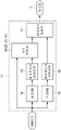
Fig. 2 is a control block diagram showing the controller in fig. 1.
Fig. 3 is a block diagram showing the command limiting unit according to the first and fourth embodiments.
Fig. 4 is an explanatory diagram showing a relationship between the slip ratio and the command allowable range in the first embodiment.
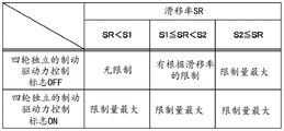
Fig. 5 is an explanatory diagram showing the relationship between the slip ratio, the braking/driving force control flag, and the limitation of the command allowable range in the first embodiment.
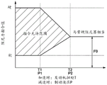
Fig. 6 is a characteristic line diagram showing an example of temporal changes in the slip ratio, the braking/driving force control flag, and the damping force allowable rate.
Fig. 7 is a block diagram showing a command limiting unit according to the second embodiment.
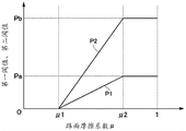
Fig. 8 is an explanatory diagram showing a relationship between the longitudinal acceleration and the command allowable range in the second embodiment.
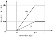
Fig. 9 is an explanatory diagram showing the relationship between the road friction coefficient and the first and second threshold values of the front-rear acceleration in the second embodiment.
Fig. 10 is an explanatory diagram showing the relationship between the front-rear acceleration and the restriction of the braking/driving force control flag and the command allowable range in the second embodiment.
Fig. 11 is a block diagram showing a command limiting unit according to the third embodiment.
Fig. 12 is an explanatory diagram showing a relationship between the engine torque, the brake hydraulic pressure, and the command allowable range in the third embodiment.
Fig. 13 is an explanatory diagram showing the relationship between the road friction coefficient and the first and second threshold values of the engine torque in the third embodiment.
Fig. 14 is an explanatory diagram showing the relationship between the road surface friction coefficient and the first and second threshold values of the brake hydraulic pressure in the third embodiment.
Fig. 15 is an explanatory diagram showing the relationship between the engine torque, the brake fluid pressure, and the braking/driving force control flag and the restriction of the command allowable range in the third embodiment.
Fig. 16 is an explanatory diagram showing a relationship between the slip ratio and the command allowable range in the fourth embodiment.
Fig. 17 is a characteristic line diagram showing an example of temporal changes in the current command value, the ABS operation flag, and the slip ratio in the comparative example.
Fig. 18 is a characteristic line diagram showing an example of temporal changes in the current command value, the ABS operation flag, and the slip ratio in the fourth embodiment.
Fig. 19 is a characteristic line graph showing the frequency characteristic of the power spectral density of the sprung vibration at the rear wheel side position in the comparative example and the fourth embodiment.
Fig. 20 is a characteristic line diagram showing frequency characteristics of power spectral density of sprung vibration at the front wheel side position in the comparative example and the fourth embodiment.
Fig. 21 is a characteristic line graph showing the frequency characteristic of the power spectral density of the sprung vibration at the driver seat position in the comparative example and the fourth embodiment.
Fig. 22 is an explanatory diagram showing a relationship between the slip ratio and the command allowable range in the first modification.
Fig. 23 is an explanatory diagram showing a relationship between the slip ratio and the command allowable range in the second modification.
Fig. 24 is an explanatory diagram showing a relationship between the slip ratio and the command allowable range in the third modification.
Detailed Description
Hereinafter, a vehicle control device, a vehicle control method, and a vehicle control system according to embodiments of the present invention will be described in detail with reference to the accompanying drawings, taking as an example a case where the vehicle control device, the vehicle control method, and the vehicle control system are applied to a four-wheel automobile.
Fig. 1 shows a vehicle control system 1 according to an embodiment. The vehicle control system 1 is constituted by a suspension device 5 constituting a damping force generating device, and a controller 11 constituting a vehicle control device. Here, in fig. 1, for example, left and right front wheels and left and right rear wheels (hereinafter, collectively referred to as wheels 3) are provided on the lower side of a vehicle body 2 constituting a vehicle body of the vehicle. The wheel 3 includes a tire 4, and the tire 4 functions as a spring that absorbs fine irregularities on a road surface.
The suspension 5 is arranged to be mounted between the body 2 of the vehicle and the wheel 3 of the vehicle. The suspension device 5 includes a suspension spring 6 (hereinafter, referred to as a spring 6) and a damping force adjustable shock absorber (hereinafter, referred to as a variable damper 7) provided between the vehicle body 2 and the wheel 3 in parallel with the spring 6.
Note that fig. 1 shows a case where 1 set of suspension devices 5 is provided between the vehicle body 2 and the wheels 3. However, the suspension devices 5 are provided independently in four sets, for example, between the four wheels 3 and the vehicle body 2, and only one of the sets is schematically shown in fig. 1.
Here, the variable damper 7 of the suspension device 5 is configured using a damping force adjusting type hydraulic shock absorber provided between the vehicle body 2 and the wheel 3. In order to continuously adjust the characteristics of the generated damping force (i.e., damping force characteristics) from the hard characteristics (hard characteristics) to the soft characteristics (soft characteristics), the variable damper 7 is provided with a damping force variable actuator 8 including a damping force adjustment valve and the like. Note that the damping force variable actuator 8 may not necessarily have a configuration in which the damping force characteristics are continuously adjusted, and may be configured to adjust the damping force in multiple stages of two or more stages, for example. The variable damper 7 may be of a pressure control type or a flow control type. The variable damper 7 may also be of a type that controls viscosity such as a magnetic viscous fluid or an electric viscous fluid.
The controller 11 constitutes a vehicle control device. The controller 11 is constituted by, for example, a microcomputer as a control device for controlling the damping characteristic of the variable damper 7. The Controller 11 is connected to, for example, a CAN10(Controller Area Network) as a communication Network required for data communication. The controller 11 acquires parameters related to the running of the vehicle through the CAN 10. In this case, the parameters related to the running of the vehicle include, for example, wheel speed, slip ratio, front-rear acceleration, engine torque, brake hydraulic pressure, road surface friction coefficient, four-wheel independent braking/driving force control flag, and the like. The output side of the controller 11 is connected to the damping force variable actuator 8 of the variable damper 7.
The controller 11 has a storage unit 11A including a ROM, a RAM, a nonvolatile memory, and the like. The storage unit 11A of the controller 11 stores various programs, information (vehicle information), data, and the like for controlling the variable damper 7.
As shown in fig. 2, the controller 11 includes a vertical VSE (vehicle State estimation)12, a ride comfort control logic 13, a plane VSE14, a steering stability control logic 15, a command limiting unit 16, and a control command selecting unit 17.
The vertical VSE12 performs Estimation of the Vehicle State in the vertical direction (Vehicle State Estimation). The vertical VSE12 is configured, for example, in the same manner as the traveling state estimating unit disclosed in patent document 1. The vertical VSE12 derives wheel speed from the CAN signal propagated from CAN 10. The vertical VSE12 estimates the state of the vehicle body 2 in the vertical direction from the change in the wheel speed. Specifically, the vertical VSE12 estimates the stroke speed, the bounce rate, the roll rate (roll rate), the pitch rate, the sprung velocity, and the like of each wheel based on the wheel speed. The vertical VSE12 obtains the wheel speed, steering angle, vehicle body lateral direction speed, actual yaw rate, and the like from the CAN signal, and estimates the stroke speed of each wheel and the like using them.
The ride comfort control logic 13 calculates a command value to the variable damper 7 (force generation mechanism) based on the stroke speed of each wheel, the sprung speed, and the like. The ride comfort control logic 13 outputs a damping force command value for reducing vertical vibration on the spring from the stroke speed, the sprung speed, and the like, based on, for example, a skyhook control rule. In this case, the damping force command value is a ride comfort control logic command value.
The plane VSE14 estimates the vehicle state in the plane direction. The plane VSE14 obtains the wheel speed, the steering angle, the vehicle body lateral speed, the actual yaw rate, and the like from the CAN signal propagated from the CAN10, and estimates the lateral acceleration and the like using these. The steering stability control logic 15 outputs a second command value for improving the steering stability of the vehicle based on the lateral acceleration or the like. The steering stability control logic 15 calculates a second command value for changing the damping force characteristic of the variable damper 7 to a hard characteristic as the lateral acceleration increases, for example. At this time, the second instruction value is a steering stability control logic instruction value.
The command limiting unit 16 constitutes a control unit of the vehicle control device. The command limiting unit 16 performs calculation based on the input information and outputs the calculation result. The command limiting unit 16 obtains parameters related to the running of the vehicle, such as a slip ratio, a four-wheel independent braking/driving force control flag, and the like, through the CAN 10. As shown in fig. 3, a slip ratio and a four-wheel independent braking/driving force control flag are input to the command limiting unit 16.
The command limiting unit 16 obtains a first command value serving as a damping force control command that limits a variable range of a damping force generated by a suspension device 5 (damping force generating device) provided between the vehicle body 2 and the wheel 3 of the vehicle, based on the obtained parameter relating to the travel of the vehicle. Specifically, the command limiting unit 16 limits the damping force command value output from the ride comfort control logic 13 based on a parameter related to the running of the vehicle. Thus, the command limiting unit 16 obtains the first command value from the damping force command value. Therefore, the damping force command value is the pre-limit command value. In contrast, the first command value is a post-limit command value. The command limiting unit 16 outputs the obtained first command value to the control command selecting unit 17.
The command limiting unit 16 limits the variable range of the damping force based on the slip ratio SR of the wheel 3 among the parameters related to the running of the vehicle. At this time, the variable range of the damping force corresponds to the command allowable range indicated by the hatched portion in fig. 4. As shown in fig. 4, the command limiting portion 16 changes the command allowable range based on the slip ratio SR of the wheel 3.
Specifically, the command limitation unit 16 does not set a limitation on the command allowable range when the slip ratio SR is smaller than the preset first threshold value S1 (SR < S1). At this time, the first command value is the same value as the damping force command value. Thus, the damping force can be generated in all ranges between hard and soft.
When the slip ratio SR is equal to or greater than the first threshold S1 and is smaller than the second threshold S2 that is larger than the first threshold S1 (S1 ≦ SR < S2), the command limiting unit 16 limits the command allowable range so that the command allowable range becomes narrower as the slip ratio SR increases. At this time, the damping force command value is limited so that the first command value is within the command allowable range. Therefore, the range in which the damping force can be generated is narrower than in the case where the slip ratio SR is smaller than the first threshold value S1 (SR < S1).
When the slip ratio SR is equal to or greater than the second threshold value S2 (S2 ≦ SR), the command limiting unit 16 limits the command allowable range to be narrower than the command allowable range when the slip ratio SR is smaller than the second threshold value S2. Specifically, when the slip ratio SR is equal to or greater than the second threshold value S2, the command limiting unit 16 sets the command allowable range to a predetermined value F0 set in advance. At this time, the first command value is the predetermined value F0 regardless of the damping force command value. Note that the prescribed value F0 is set to, for example, a value that generates the same damping force as an existing damper (conventional damper) in which the damping force is fixed.
The command limiting unit 16 limits the damping force command value output from the ride comfort control logic 13 to a value within a command allowable range. Therefore, when the slip ratio SR is smaller than the first threshold value S1, the command limiting unit 16 outputs the first command value that is the same as the damping force command value output from the ride comfort control logic 13. When the slip ratio SR is equal to or greater than the first threshold value S1 and smaller than the second threshold value S2, the command limiting unit 16 limits the damping force command value to a value within the command allowable range set according to the slip ratio SR, and outputs the first command value with the limited value. When the slip ratio SR is equal to or greater than the second valve value S2, the command limiting unit 16 outputs a first command value set to a predetermined value F0.
In this case, the first threshold value S1 and the second threshold value S2 are set in advance in consideration of, for example, the characteristics of the tire 4. The force (for example, braking force, driving force, etc.) that can be generated by the tire 4 is the maximum when the slip ratio SR is 10% to 20%, and decreases more than that. When the slip ratio SR increases and goes out of the range of 10% -20%, ABS (anti-lock brake system) or TCS (traction control system) is controlled so that the slip ratio SR becomes the range of 10% -20%. The second valve value S2 is set to a value less than the slip ratio at which ABS or TCS operates. For example, the second threshold S2 is set to 10% as a slip ratio in consideration of the non-operation of the ABS or the TCS. On the other hand, the first threshold value S1 may be smaller than the second threshold value S2. Therefore, the first threshold value S1 is set to a value (5%) of about half the second threshold value S2, for example. Note that the first threshold S1 may be a value of 5% or more, or a value of 5% or less. The first threshold S1 and the second threshold S2 are appropriately set by tuning.
Further, the command limitation unit 16 can limit the command allowable range not only based on the slip ratio SR but also during the four-wheel independent braking/driving force control. For example, when four-wheel independent braking/driving force control is performed in which ABS, TCS, and ESC (vehicle body stability system) are operated, rapid wheel speed variation occurs, and accuracy of estimation of the vehicle state deteriorates. Therefore, when the four-wheel independent braking/driving force control is operated, the command limiting unit 16 maximizes the limitation amount of the command allowable range. In this case, the maximum limit amount may be changed instantaneously or gradually with the passage of time.
As shown in fig. 3, in order to limit the command allowable range by the four-wheel independent braking/driving force control, a four-wheel independent braking/driving force control flag is input to the command limiting unit 16. At this time, the braking-driving force control flag is a control flag for independently braking or driving all the wheels of the vehicle. The braking/driving force control flag includes, for example, an ABS operation flag, a TCS operation flag, and an ESC operation flag. For example, a vehicle includes an ABS as a safety device for preventing locking of wheels, a TCS as a safety device for suppressing wheel slip, and an ESC as a safety device for preventing vehicle sideslip. When all of ABS, TCS, and ESC are not operated, the braking/driving force control flag is turned OFF. When any one of the ABS, TCS, and ESC is operated, the braking/driving force control flag is turned ON. When the braking/driving force control flag in the "ON" state is turned "ON", the command limiting unit 16 maximizes the limiting amount of the command allowable range.
Therefore, when the braking/driving force control flag for driving and braking the vehicle independently for all the wheels including the wheel is turned ON among the parameters related to the running of the vehicle, the command limitation unit 16 limits the command allowable range (see fig. 5) to be narrower than the command allowable range when the command allowable range is smaller than the second threshold value S2. Therefore, when the braking/driving force control flag is turned "ON", the command limiting unit 16 outputs the first command value set to the predetermined value F0.
As shown in fig. 2, the control command selecting unit 17 is input with a first command value output from the command limiting unit 16 and a second command value output from the steering stability control logic 15. The control command selecting unit 17 selects any one of these command values. For example, in a state where the vehicle is stably driven, the control command selecting unit 17 selects the first command value output from the command limiting unit 16 in order to give priority to the riding comfort. On the other hand, in a state where the vehicle is not traveling stably, the control command selection unit 17 selects the second command value output from the steering stability control logic 15 in order to prioritize the steering stability. The control command selecting unit 17 may select a command value by comparing the magnitudes of two input command values, or may select a command value based on information on the vehicle state. The control command selection unit 17 outputs a command value selected as a current command value to the damping force variable actuator 8 of the variable damper 7.
The vehicle control system 1 of the embodiment has the configuration described above. Next, a process of variably controlling the damping force characteristic of the variable damper 7 using the controller 11 will be described.
In the variable damper 7 installed between the vehicle body 2 and the wheel 3, a command value (control command) from the controller 11 is input as a command current to the damping-force variable actuator 8. Thereby, the damping force variable actuator 8 is driven to variably control the flow passage area of the oil flowing through the variable damper 7. As a result, the damping force characteristic of the variable damper 7 is variably controlled between the hard characteristic (hard characteristic) and the soft characteristic (soft characteristic) in accordance with the command value.
However, in the vehicle control device described in patent document 1, the damping force of the damping force variable shock absorber is determined based on the wheel speed even if the estimation accuracy of the vehicle state is degraded in a state where the brake driving control is not operated. Therefore, the control accuracy may be degraded, and the riding comfort and the steering stability of the vehicle may not be ensured satisfactorily.
In contrast, the controller 11 of the present embodiment includes the command limiting unit 16, and the command limiting unit 16 limits the command allowable range of the damping force generated by the variable damper 7 of the suspension device 5 provided between the vehicle body 2 and the wheel 3 of the first command value vehicle based on a parameter related to the running of the vehicle such as the slip ratio, obtains the first command value, and outputs the obtained first command value.
Therefore, the command limiting unit 16 can adjust the damping force of the variable damper 7 according to the slip ratio SR when the slip occurs. Fig. 6 shows an example of a temporal change in the slip ratio, the four-wheel independent braking/driving force control flag, and the damping force allowable rate when the command limiting unit 16 of the present embodiment is used. As shown in fig. 6, between time t1 and time t2, the slip ratio SR increases as compared to the first threshold value S1. At this time, as the slip ratio SR increases, the command limiting unit 16 decreases the damping force allowable rate from 100%, thereby reducing the command allowable range. Between time t2 and time t3, the slip ratio SR decreases compared to the first threshold S1. Therefore, the command limiting unit 16 returns the damping force allowable rate to 100%, and cancels the limitation of the command allowable range. Between time t3 and time t4, the slip ratio SR increases compared to the first threshold S1. Therefore, the command limiting unit 16 reduces the damping force allowable rate from 100% according to the slip rate SR. Between the time t4 and the time t5, the four-wheel independent braking-driving force control flag is turned ON. Therefore, the command limiting unit 16 minimizes the damping force allowable rate (for example, 0%) and minimizes the command allowable range. Between time t5 and time t6, the slip ratio SR is a value between the first threshold value S1 and the second threshold value S2. Therefore, the command limiting unit 16 reduces the damping force allowable rate from 100% according to the slip rate SR. After time t6, the slip ratio SR decreases compared to the first threshold value S1. Therefore, the command limiting unit 16 returns the damping force allowable rate to 100%, and cancels the limitation of the command allowable range.
In this manner, the command limiting unit 16 can bring the damping force of the variable damper 7 close to the same level as that of, for example, a conventional damper, in accordance with the slip ratio SR at the time of the occurrence of the slip. As a result, even when a slip occurs, ride comfort and steering stability equal to those of a conventional damper can be ensured, and ride comfort and steering stability of the vehicle can be ensured well.
In the present embodiment, for example, it is not necessary to detect a decrease in the accuracy of the estimation of the vehicle state, such as during the operation of the ABS, TCS, or ESC or during the braking operation. That is, the controller 11 may detect only the slip ratio SR, for example, and may adjust the damping force of the variable damper 7 according to the slip ratio SR. As a result, the damping force of the variable damper 7 can be changed earlier than in the vehicle control device described in patent document 1.
Therefore, the command limiting unit 16 of the present embodiment obtains a parameter related to the traveling of the vehicle, limits a command allowable range (variable range) of the damping force generated by the suspension device 5 (damping force generating device) provided between the vehicle body 2 and the wheel 3 of the vehicle, obtains a first command value (damping force control command), and outputs the obtained first command value. This can suppress delay in the intervention of damping force control suitable for the road surface condition on which the vehicle is traveling, and can improve ride comfort and steering stability.
The command limiting unit 16 limits the command allowable range of the damping force based on the slip ratio SR of the wheel 3 among the parameters related to the running of the vehicle. At this time, the command limiting unit 16 does not limit the command allowable range of the damping force when the slip ratio SR is smaller than the preset first threshold value S1. When the slip ratio SR is greater than the first threshold value S1 or the first threshold value S1 and smaller than the second threshold value S2 that is greater than the first threshold value S1, the command limiting unit 16 limits the command allowable range of the damping force so as to narrow as the slip ratio SR increases. When the slip ratio SR is larger than the second threshold value S2 or the second threshold value S2, the command limiting unit 16 limits the command allowable range of the damping force so as to be narrower than the command allowable range of the damping force when the slip ratio SR is smaller than the second threshold value S2.
Thus, the command limiting unit 16 can limit the command allowable range of the damping force in accordance with the slip ratio SR even in a state where the slip ratio SR is smaller than the second threshold value S2. Therefore, for example, when the second threshold value S2 is set to a value smaller than the slip ratio SR at which the ABS, TCS, ESC, or the like is operated, the command limitation unit 16 can limit the command allowable range of the damping force according to the slip ratio SR even in a state where a decrease in the estimation accuracy of the stroke speed is not detected. Thus, the command limiting unit 16 can bring the damping force close to a desired value.
Further, when the slip ratio SR is equal to or greater than the first threshold value S1 and less than the second threshold value S2, the command limiting unit 16 limits the command allowable range of the damping force so that the command allowable range of the damping force becomes narrower as the slip ratio SR increases. At this time, the command limiting unit 16 gradually decreases the command allowable range of the damping force as the slip ratio SR increases. Therefore, when the slip ratio SR increases, the command allowable range of the damping force does not suddenly change.
When the slip ratio SR is greater than the second threshold value S2 or the second threshold value S2, the command limiting unit 16 sets the command allowable range of the damping force to a predetermined value F0. For example, when the predetermined value F0 is set to a value that is approximately equal to the damping force of the conventional damper, the command limitation unit 16 can cause the damping force of the variable damper 7 to approach the damping force of the conventional damper by an increase in the slip ratio SR. As a result, even when a slip occurs, ride comfort and steering stability comparable to those of conventional dampers can be ensured, so that ride comfort and steering stability of the vehicle can be well ensured.
Further, when acquiring a control flag (braking/driving force control flag) for braking/driving all the wheels of the vehicle including the wheel 3 independently among the parameters relating to the traveling of the vehicle, the command limiting unit 16 limits the command allowable range of the damping force so as to be narrower than the command allowable range of the damping force when the value is smaller than the second threshold value S2. Thus, in a running state of the vehicle in which the ABS, TCS, ESC, or the like is operated, for example, the command limitation unit 16 can narrow the command allowable range of the damping force and can bring the damping force close to a desired value.
Next, fig. 2, 7 to 10 show a second embodiment. The second embodiment is characterized in that the command limiting unit limits the variable range of the damping force using the front-rear acceleration and the road surface friction coefficient, or limits the variable range of the damping force using the four-wheel independent brake drive control flag. Note that in the second embodiment, the same components as those in the first embodiment are denoted by the same reference numerals, and description thereof is omitted.
As shown in fig. 2, in the second embodiment, the controller 11 includes a command limiting unit 21 instead of the command limiting unit 16 of the first embodiment. The command limiting unit 21 constitutes a control unit of the vehicle control device.
The command limiting unit 21 is configured in the same manner as the command limiting unit 16 of the first embodiment. As shown in fig. 7, the command limiting unit 21 obtains parameters related to the running of the vehicle, such as the front-rear acceleration G of the vehicle, the road surface friction coefficient μ, and the four-wheel independent braking/driving force control flag, through the CAN 10. The command limiting unit 21 limits a variable range (command allowable range) of the damping force generated by the suspension device 5 provided between the vehicle body 2 and the wheel 3 of the vehicle, based on the acquired parameter relating to the running of the vehicle, and obtains a first command value as the damping force control command. The command limiting unit 21 outputs the obtained first command value.
As shown in fig. 8 and 9, the command limiting unit 21 limits the command allowable range of the damping force based on the front-rear acceleration G of the wheel 3 and the road surface friction coefficient μ among the parameters related to the running of the vehicle. As shown by the hatched portion in fig. 8, when the front-rear acceleration G is smaller than the first threshold G1 (G < G1), the command restricting unit 21 does not restrict the command allowable range. When the front-rear acceleration G is equal to or greater than the first threshold G1 and smaller than the second threshold G2 that is greater than the first threshold G1 (G1 ≦ G < G2), the command limiting unit 21 limits the command allowable range so that the command allowable range becomes narrower as the front-rear acceleration G increases. When the front-rear acceleration G is equal to or greater than the second threshold value G2 (G2 ≦ G), the command limiting unit 21 limits the command allowable range to be narrower than the command allowable range when the front-rear acceleration G is smaller than the second threshold value G2. Specifically, when the front-rear acceleration G is equal to or greater than the second valve value G2, the command limiting unit 21 sets the command allowable range to a predetermined value F0.
At this time, the command limiting unit 21 varies the first threshold G1 and the second threshold G2 in accordance with the road surface friction coefficient μ (see fig. 9). The reason for this is that a general vehicle cannot generate acceleration and deceleration equal to or higher than the road surface friction coefficient μ. For example, when the road surface friction coefficient μ is smaller than the first reference value μ 1 (for example, μ 1 ═ 0.1) (μ < μ 1), the road surface friction coefficient μ is too small, and therefore it is difficult to control the vehicle state by the suspension device 5. Therefore, the command limiting unit 21 sets both the first threshold G1 and the second threshold G2 to the minimum value (for example, G1)、G2=0m/s 2 ). In this case, the command limiting unit 21 minimizes the command allowable range. The minimum value of the first threshold value G1 and the minimum value of the second threshold value G2 may be different values from each other.
When the road surface friction coefficient μ is equal to or greater than the first reference value μ 1 and is smaller than the second reference value μ 2 (for example, μ 2 is 0.8) (μ 1 ≦ μ < μ 2), the command limiting unit 21 increases the first threshold G1 and the second threshold G2 as the road surface friction coefficient μ increases. At this time, the increase rate of the second threshold G2 is greater than the increase rate of the first threshold G1. Therefore, the second threshold G2 is a larger value than the first threshold G1.
When the road surface friction coefficient μ is equal to or greater than the second reference value μ 2(μ ≧ μ 2), the road surface friction coefficient μ is sufficiently large, and therefore, even if the road surface friction coefficient μ changes, the change in the state of the vehicle is small. Therefore, the command limiting section 21 sets the first threshold value G1 and the second threshold value G2 to the maximum values Ga and Gb based on the second reference value μ 2. In this case, the maximum value Ga is the maximum value of the first threshold G1 (for example, Ga is 0.1 m/s) 2 ). The maximum value Gb is the maximum value of the second threshold value G2 (e.g. Gb is 0.4 m/s) 2 ). The maximum value Gb is a value larger than the maximum value Ga. Not limited to the example shown in fig. 9, the first threshold G1 and the second threshold G2 may be appropriately set according to tuning.
The command limiting unit 21 limits the damping force command value output from the ride comfort control logic 13 to a value within a command allowable range. Therefore, when the front-rear acceleration G is smaller than the first threshold value G1, the command limitation unit 21 outputs a first command value that is the same as the damping force command value output from the ride comfort control logic 13. When the front-rear acceleration G is equal to or greater than the first threshold G1 and is smaller than the second threshold G2, the command limiting unit 21 limits the damping force command value to a value within a command allowable range set in accordance with the front-rear acceleration G, and outputs the first command value with the limited value. When the front-rear acceleration G is equal to or greater than the second valve value G2, the command limiting unit 21 outputs a first command value set to a predetermined value F0.
The command limitation unit 21 can limit the command allowable range not only based on the front-rear acceleration G but also during the four-wheel independent braking/driving force control (see fig. 10). Therefore, when the four-wheel independent braking/driving force control is operated, the command limiting unit 21 maximizes the limitation amount of the command allowable range. At this time, the command limiting unit 21 outputs the first command value set to the predetermined value F0, as in the case where the longitudinal acceleration G is equal to or greater than the second valve value G2.
Therefore, also in the second embodiment, substantially the same operational effects as those in the first embodiment can be obtained. In the second embodiment, the command limiting unit 21 limits the command allowable range of the damping force based on the longitudinal acceleration G of the vehicle among the parameters related to the running of the vehicle. Therefore, as the front-rear acceleration G becomes larger, the command restricting portion 21 can narrow the command allowable range of the damping force, and make the damping force of the variable damper 7 approach, for example, the same level of the damping force as that of the conventional damper.
Further, the command limiting unit 21 varies the first threshold G1 and the second threshold G2 for changing the limitation of the variable range of the damping force, based on the road surface friction coefficient μ of the road surface on which the vehicle is traveling. Thus, the command limiting unit 21 can adjust the command allowable range of the damping force in consideration of the road surface friction coefficient μ.
Next, fig. 2, 11 to 15 show a third embodiment. The third embodiment is characterized in that the command limiting unit limits the variable range of the damping force using the engine torque, the brake hydraulic pressure, and the road surface friction coefficient, or limits the variable range of the damping force using the four-wheel independent brake drive control flag. Note that, in the third embodiment, the same components as those in the first embodiment are denoted by the same reference numerals, and the description thereof is omitted.
As shown in fig. 2, in the third embodiment, the controller 11 includes a command limiting unit 31 instead of the command limiting unit 16 of the first embodiment. The command limiting unit 31 constitutes a control unit of the vehicle control device.
The command limiting unit 31 is configured similarly to the command limiting unit 16 of the first embodiment. As shown in fig. 11, the command limiting unit 31 obtains parameters related to the running of the vehicle, such as the engine torque T, the brake hydraulic pressure P, the road surface friction coefficient μ, and the four-wheel independent braking/driving force control flag, through the CAN 10. At this time, the engine torque T and the brake hydraulic pressure P correspond to braking/driving torques (driving torque and braking torque) applied to the wheels.
The command limiting unit 31 limits a variable range (command allowable range) of the damping force generated by the suspension device 5 provided between the vehicle body 2 and the wheel 3 of the vehicle, based on the acquired parameter relating to the running of the vehicle, and obtains a first command value serving as a damping force control command. At this time, the command limiting unit 31 limits the damping force command value output from the ride comfort control logic 13 to a value within the command allowable range. The command limiting unit 31 outputs the obtained first command value.
As shown in fig. 12 and 13, when the vehicle accelerates, the command limiting unit 31 limits the command allowable range of the damping force based on the engine torque T and the road surface friction coefficient μ among the parameters relating to the traveling of the vehicle. As shown by the hatched portion in fig. 12, the command limiting unit 31 does not set a limit to the command allowable range when the engine torque T is smaller than the first threshold value T1 (T < T1). When the engine torque T is equal to or higher than the first threshold T1 and is smaller than a second threshold T2 that is larger than the first threshold T1 (T1 ≦ T < T2), the command limiting unit 31 limits the command allowable range so that the command allowable range becomes narrower as the engine torque T increases. When the engine torque T is equal to or greater than the second threshold value T2 (T2 ≦ T), the command limiting unit 31 limits the command allowable range so as to be narrower than the command allowable range when the engine torque T is smaller than the second threshold value T2. Specifically, when the engine torque T is equal to or greater than the second threshold value T2, the command limiting unit 31 sets the command allowable range to a predetermined value F0 set in advance.
As shown in fig. 12 and 14, when the vehicle decelerates, the command limiting unit 31 limits the command allowable range of the damping force based on the brake hydraulic pressure P and the road surface friction coefficient μ among the parameters relating to the traveling of the vehicle. As shown by the hatched portion in fig. 12, when the brake fluid pressure P is smaller than the first threshold P1 (P < P1), the command limitation unit 31 does not limit the command allowable range. When the brake fluid pressure P is equal to or higher than the first threshold value P1 and is lower than a second threshold value P2 that is higher than the first threshold value P1 (P1 ≦ P < P2), the command restricting unit 31 restricts the command allowable range so that the command allowable range becomes narrower as the brake fluid pressure P increases. When the brake fluid pressure P is equal to or greater than the second threshold value P2 (P2 ≦ P), the command limiting unit 31 limits the command allowable range to be narrower than the command allowable range when the brake fluid pressure P is less than the second threshold value P2. Specifically, when the brake fluid pressure P is equal to or greater than the second valve value P2, the command limiting unit 31 sets the command allowable range to a predetermined value F0 that is set in advance.
At this time, the command limiting unit 31 varies the first threshold values T1 and P1 and the second threshold values T2 and P2 in accordance with the road surface friction coefficient μ (see fig. 13 and 14). For example, when the road surface friction coefficient μ is smaller than the first reference value μ 1(μ < μ 1), the command limiting unit 31 sets any one of the first threshold value T1 and the second threshold value T2 to a minimum value (for example, T1 or T2 is 0N · m). In this case, the command limiting unit 31 minimizes the command allowable range. The minimum value of the first threshold value T1 and the minimum value of the second threshold value T2 may be different values from each other.
When the road surface friction coefficient μ is smaller than the first reference value μ 1(μ < μ 1), the command limiting unit 31 sets either one of the first threshold value P1 and the second threshold value P2 to a minimum value (for example, P1 and P2 are 0 MPa). In this case, the command limiting unit 31 minimizes the command allowable range. The minimum value of the first threshold value P1 and the minimum value of the second threshold value P2 may be different values from each other.
When the road surface friction coefficient μ is equal to or greater than the first reference value μ 1 and is smaller than the second reference value μ 2(μ 1 ≦ μ < μ 2), the command limiting unit 31 increases the first threshold value T1 and the second threshold value T2 and increases the first threshold value P1 and the second threshold value P2 as the road surface friction coefficient μ increases. At this time, the increase rate of the second threshold value T2 is greater than the increase rate of the first threshold value T1. Therefore, the second threshold value T2 is a larger value than the first threshold value T1. Also, the increase rate of the second threshold value P2 is greater than the increase rate of the first threshold value P1. Therefore, the second threshold P2 is a larger value than the first threshold P1.
When the road surface friction coefficient μ is equal to or greater than the second reference value μ 2(μ ≧ μ 2), the command limiting unit 31 sets the first threshold T1 and the second threshold T2 to the maximum values Ta, Tb corresponding to the second reference value μ 2. In this case, the maximum value Ta is the maximum value of the first threshold value T1 (for example, Ta is 50N · m). The maximum value Tb is the maximum value of the second threshold value T2 (for example, Tb 100N · m). The maximum value Tb is a value larger than the maximum value Ta.
Similarly, when the road surface friction coefficient μ is equal to or greater than the second reference value μ 2(μ ≧ μ 2), the command restricting unit 31 sets the first threshold P1 and the second threshold P2 to the maximum values Pa and Pb corresponding to the second reference value μ 2. At this time, the maximum value Pa is the maximum value of the first threshold P1 (for example, Pa 1 MPa). The maximum value Pb is the maximum value of the second threshold value P2 (for example, Pb 5 MPa). The maximum value Pb is a value larger than the maximum value Pa. Not limited to the examples shown in fig. 13 and 14, the first threshold values T1 and P1 and the second threshold values T2 and P2 may be set appropriately by tuning.
The command limitation unit 31 can limit the command allowable range (see fig. 15) not only based on the engine torque T and the brake hydraulic pressure P but also in the four-wheel independent braking/driving force control. Therefore, when the four-wheel independent braking/driving force control is operated, the command limiting unit 31 maximizes the limitation amount of the command allowable range. At this time, the command limiting unit 31 outputs a first command value set to a predetermined value F0.
Therefore, also in the third embodiment, substantially the same operational effects as those in the first embodiment can be obtained. In the third embodiment, the command limiting unit 31 limits the command allowable range of the damping force based on the engine torque T among the parameters related to the running of the vehicle. The command limiting unit 31 limits the command allowable range of the damping force based on the brake fluid pressure P in the parameter related to the running of the vehicle. Here, the engine torque T corresponds to the front-rear acceleration when the vehicle is accelerated. The brake hydraulic pressure P corresponds to the front-rear acceleration when the vehicle decelerates. Therefore, the third embodiment can also obtain the same operational effects as the second embodiment.
The command limiting unit 31 varies the first threshold values T1 and P1 and the second threshold values T2 and P2 for changing the limitation of the variable range of the damping force, based on the road surface friction coefficient μ of the road surface on which the vehicle travels. Thus, the command limiting unit 31 can adjust the command allowable range of the damping force in consideration of the road surface friction coefficient μ.
Next, fig. 2, 3, and 16 show a fourth embodiment. A feature of the fourth embodiment is that the command limiting unit limits the variable range of the damping force such that the damping force becomes soft as the slip ratio increases. Note that, in the fourth embodiment, the same components as those in the first embodiment are denoted by the same reference numerals, and the description thereof is omitted.
As shown in fig. 2, in the fourth embodiment, the controller 11 includes a command limiting unit 41 instead of the command limiting unit 16 of the first embodiment. The command limiting unit 41 constitutes a control unit of the vehicle control device.
The command limiting unit 41 is configured in the same manner as the command limiting unit 16 of the first embodiment. As shown in fig. 3, the command limiting unit 41 obtains parameters related to the running of the vehicle, such as a slip ratio, a four-wheel independent braking/driving force control flag, and the like, by the CAN 10. The command limiting unit 41 limits a variable range (command allowable range) of the damping force generated by the suspension device 5 provided between the vehicle body 2 and the wheel 3 of the vehicle, based on the acquired parameter relating to the running of the vehicle, and obtains a first command value serving as a damping force control command. The command limiting unit 41 outputs the obtained first command value.
As shown in fig. 16, the command limiting unit 41 limits the command allowable range of the damping force based on the slip ratio SR of the wheel 3 among the parameters related to the running of the vehicle. As shown by the hatched portion in fig. 16, the command limiting unit 41 does not set a limit to the command allowable range when the slip ratio SR is smaller than the preset first threshold value S1 (SR < S1). When the slip ratio SR is equal to or higher than the first threshold value S1 and is smaller than the second threshold value S2 that is larger than the first threshold value S1 (S1 ≦ SR < S2), the command limiting unit 41 limits the command allowable range so that the command allowable range becomes narrower as the slip ratio SR increases. When the slip ratio SR is equal to or greater than the second threshold value S2 (S2 ≦ SR), the command limiting unit 41 limits the command allowable range to be narrower than the command allowable range when the slip ratio SR is smaller than the second threshold value S2.
At this time, when the slip ratio SR is equal to or greater than the second threshold value S2, the command limiting unit 41 sets the command allowable range to a predetermined value F1 set in advance. The predetermined value F1 is set to a value at which the damping force is soft, for example. Therefore, the predetermined value F1 is different from the predetermined value F0 of the first embodiment.
The command limiting unit 41 limits the damping force command value output from the ride comfort control logic 13 to a value within a command allowable range. The command limitation unit 41 can limit the command allowable range not only based on the slip ratio SR but also during the four-wheel independent braking/driving force control. Therefore, when the four-wheel independent braking/driving force control is operated, the command limiting unit 41 maximizes the limitation amount of the command allowable range. At this time, the command limiting unit 21 outputs the first command value set to the predetermined value F1, as in the case where the longitudinal acceleration G is equal to or greater than the second valve value G2.
Therefore, also in the fourth embodiment, substantially the same operational effects as those in the first embodiment can be obtained. In the fourth embodiment, the command limiting unit 41 limits the variable range (command allowable range) of the damping force so that the damping force becomes soft as the slip ratio SR increases. Therefore, even in a state where the variable range of the damping force is limited, the riding comfort can be improved.
In order to confirm this effect, the vehicle simulation was performed for the fourth embodiment and the comparative example. The control conditions disclosed in patent document 1 were used in the comparative example. It is to be noted that the vehicle model used for the simulation is a hatchback type passenger car. The road surface is a road surface which is easy to generate 2-8Hz spring vibration which affects the riding comfort. The road surface friction coefficient μ was 0.4. And the initial speed of the vehicle entering the road surface is 80 km/h. The brake pressure is 2.5 MPa.
First, the results of the comparative example are shown in fig. 17. Fig. 17 shows temporal changes in the slip ratio SR, the ABS operation flag (braking/driving force control flag), and the current command value output from the controller 11. In the comparative example, the current command value cannot be limited unless the estimation accuracy of the ABS operation is degraded (ABS operation). Therefore, the current command value is limited to make the damping force soft only when the ABS is operating.
On the other hand, the results of the fourth embodiment are shown in fig. 18. The command limiting unit 41 according to the fourth embodiment limits the damping force only by the slip ratio SR. Therefore, the current command value is limited from the vicinity of time t 40. In addition, the damping force is completely restricted to be soft near the time t 41. Therefore, the command limiting unit 41 of the fourth embodiment can limit the damping force from before the ABS is operated, and can suppress deterioration of the riding comfort.
Next, with respect to the fourth embodiment and the comparative example, fig. 19 to 21 show the Power Spectral Density (PSD) of the sprung acceleration. Fig. 19 shows the PSD of the rear wheel side position. Fig. 20 shows the PSD of the front wheel side position. Fig. 21 shows the PSD of the driver seat position. As shown in fig. 19 to 21, the fourth embodiment has a smaller gain in the vicinity of 2 to 7Hz and improves the riding comfort compared to the comparative example.
Note that, in the fourth embodiment, when the slip ratio SR is equal to or greater than the second valve value S2, the command allowable range is limited to the predetermined value F1 where the damping force is soft. However, for example, as in the first modification shown in fig. 22, when the slip ratio SR is equal to or greater than the second valve value S2, the command allowable range may be limited to a predetermined value F2 at which the damping force is hard. In this case, the steering stability can be improved when the slip ratio SR increases. The prescribed value for limiting the instruction allowable range is set appropriately by tuning. This configuration can be applied to the second and third embodiments.
In the fourth embodiment, when the slip ratio SR is equal to or greater than the second threshold value S2. The command allowable range is limited to a predetermined value F1. The present invention is not limited to this, and for example, as shown in fig. 23 and 24, when the slip ratio SR is equal to or greater than the second threshold value S2, the command allowable range (the variable range of the damping force) may be limited to a predetermined range set in advance so as to be narrower than when the slip ratio SR is smaller than the second threshold value S2. In this case, as in the second modification shown in fig. 23, the command allowable range may be limited to, for example, a range in which the damping force is between the damping force of the conventional damper and the soft damping force. As a third modification shown in fig. 24, the command allowable range may be limited to, for example, a range in which the damping force is between the damping force of a conventional damper and a firm damping force. The prescribed range within which the command allowable range is limited is set appropriately by tuning. This configuration can be applied to the second and third embodiments.
In the first and fourth embodiments, the command limiting units 16 and 41 limit the command allowable range (variable range) of the damping force so as to be narrower than the variable range of the damping force when the braking/driving force control flag (control flag) for braking/driving all the wheels of the vehicle including the wheels independently is obtained, in addition to the command allowable range (variable range) for limiting the damping force based on the slip ratio SR. However, the command limiting unit may limit the command allowable range (variable range) of the damping force only based on the slip ratio SR, without limiting the variable range of the damping force based on the control flag. This configuration can be applied to the second and third embodiments.
In the first embodiment, the controller 11 includes the plane VSE14, the steering stability control logic 15, and the control command selecting unit 17, but these may be omitted. In this case, the controller 11 outputs the limited command value through the command limiting unit 16. This configuration can be applied to the second to fourth embodiments.
In the above embodiments, the braking/driving force control flag is turned ON when the ABS, TCS, ESC are operated. However, the braking/driving force control flag may be turned ON when the braking/driving force of each wheel is controlled by the system instead of the operation of the driver, such as when the G-vector control (acceleration vector) for controlling the acceleration/deceleration of the vehicle in accordance with the lateral acceleration of the vehicle is operated, when the Moment + control (torque control) for controlling the yaw Moment in accordance with the lateral acceleration of the vehicle is operated, or when the engine torque is controlled to control the pitch of the vehicle body.
In the above embodiments, the case where the controller 11 outputs the obtained control command to the suspension device 5 has been described as an example. However, the present invention is not limited to this, and for example, a configuration may be adopted in which a control device (ECU) different from the vehicle control device is provided between the vehicle control device as the controller and the damping force generating device as the suspension device. In this case, the vehicle control device outputs the obtained control command to the damping force generation device via the different control device (ECU).
In the above embodiments, the case where the controller 11 acquires the parameters related to the traveling of the vehicle through the CAN10 is described as an example. However, the controller may acquire parameters related to the running of the vehicle from, for example, a wheel speed sensor, an acceleration sensor, another controller, or the like.
The specific numerical values described in the above embodiments are examples, and are not limited to the values described in the examples.
The embodiments described are examples, and parts of the configurations shown in different embodiments may be replaced or combined.
As the vehicle control device, the vehicle control method, and the vehicle control system according to the above-described embodiments, for example, the following embodiments can be conceived.
As a first aspect, the present invention provides a vehicle control device including a control unit that performs calculation based on input information and outputs a calculation result, wherein the control unit obtains a parameter related to traveling of a vehicle, obtains a damping force control command by limiting a variable range of a damping force generated by a damping force generation device provided between a vehicle body of the vehicle and a wheel of the vehicle based on the obtained parameter related to traveling of the vehicle, and outputs the obtained damping force control command.
As a second aspect, in the first aspect, the control unit limits the variable range of the damping force based on a slip ratio of the wheel in a parameter related to traveling of the vehicle.
As a third aspect, in the second aspect, the control unit does not limit the variable range of the damping force when the slip ratio is smaller than a preset first threshold, limits the variable range of the damping force so that the variable range of the damping force becomes narrower as the slip ratio increases when the slip ratio is the first threshold or larger than the first threshold and smaller than a second threshold larger than the first threshold, and limits the variable range of the damping force so that the variable range of the damping force becomes narrower than the variable range of the damping force when the slip ratio is smaller than the second threshold or larger than the second threshold.
As a fourth aspect, in the third aspect, the control unit is configured to, when a control flag for braking and driving all wheels of the vehicle including the wheel independently is acquired in the parameter relating to the traveling of the vehicle, limit the variable range of the damping force so as to be narrower than the variable range of the damping force when the variable range of the damping force is smaller than the second threshold value.
As a fifth aspect, in the third aspect, the control unit may set the variable range of the damping force to a predetermined value set in advance when the slip ratio is the second threshold value or greater.
As a sixth aspect, in the third aspect, the control unit sets the variable range of the damping force to a predetermined range set in advance when the slip ratio is equal to or greater than the second threshold value.
As a seventh aspect, in the first aspect, the control unit limits the variable range of the damping force based on a longitudinal acceleration of the vehicle in a parameter related to traveling of the vehicle.
As an eighth aspect, in the seventh aspect, the control unit varies a threshold value for changing the limit of the variable range of the damping force based on a road surface friction coefficient of a road surface on which the vehicle travels.
As a ninth aspect, in the first aspect, the control portion limits the variable range of the damping force based on a braking/driving torque applied to the wheel among parameters related to traveling of the vehicle.
As a tenth aspect, a vehicle control method obtains a parameter relating to traveling of a vehicle, obtains a damping force control command by limiting a variable range of a damping force generated by a damping force generating device provided between a vehicle body of the vehicle and a wheel of the vehicle based on the obtained parameter relating to traveling of the vehicle, and outputs the obtained damping force control command.
A vehicle control system according to an eleventh aspect includes: a damping force generating device provided between a vehicle body of a vehicle and a wheel of the vehicle; and a controller that acquires a parameter relating to travel of the vehicle, determines a damping force control command by limiting a variable range of the damping force generated by the damping force generation device based on the acquired parameter relating to travel of the vehicle, and outputs the determined damping force control command.
Description of the reference numerals
1: a vehicle control system;
2: a vehicle body;
3: a wheel;
4: a tire;
5: a suspension device (damping force generating device);
6: suspension springs (springs);
7: a variable damper;
8: a damping force variable actuator;
10:CAN;
11: a controller (vehicle control device);
12: a vertical VSE;
13: ride comfort control logic;
14: a planar VSE;
15: a steering stability control logic;
16. 21, 31, 41: an instruction limiting unit (control unit);
17: a control command selecting unit.
Claims (11)
1. A vehicle control device includes a control unit that performs calculation based on input information and outputs a calculation result,
the control unit acquires a parameter relating to the travel of the vehicle, determines a damping force control command by limiting a variable range of a damping force generated by a damping force generation device provided between a vehicle body of the vehicle and a wheel of the vehicle on the basis of the acquired parameter relating to the travel of the vehicle, and outputs the determined damping force control command.
2. The vehicle control apparatus according to claim 1,
the control portion limits the variable range of the damping force based on a slip ratio of the wheel in a parameter related to running of the vehicle.
3. The vehicle control apparatus according to claim 2,
the control unit does not restrict the variable range of the damping force when the slip ratio is smaller than a preset first threshold value,
when the slip ratio is the first threshold value or is greater than the first threshold value and is smaller than a second threshold value that is greater than the first threshold value, the variable range of the damping force is limited such that the variable range of the damping force is narrowed as the slip ratio increases,
when the slip ratio is the second threshold value or greater than the second threshold value, the variable range of the damping force is limited to be narrower than the variable range of the damping force when the slip ratio is less than the second threshold value.
4. The vehicle control apparatus according to claim 3,
the control unit limits the variable range of the damping force so as to be narrower than the variable range of the damping force when the variable range of the damping force is smaller than the second threshold value, when acquiring a control flag for braking and driving all wheels of the vehicle including the wheel independently, among the parameters related to the running of the vehicle.
5. The vehicle control apparatus according to claim 3,
the control unit sets the variable range of the damping force to a predetermined value set in advance when the slip ratio is equal to or greater than the second threshold value.
6. The vehicle control apparatus according to claim 3,
the control unit sets the variable range of the damping force to a predetermined range set in advance when the slip ratio is equal to or greater than the second threshold value.
7. The vehicle control apparatus according to claim 1,
the control portion limits the variable range of the damping force based on a front-rear acceleration of the vehicle among parameters related to the running of the vehicle.
8. The vehicle control apparatus according to claim 7,
the control unit varies a threshold value for changing a limit of the variable range of the damping force based on a road surface friction coefficient in a road surface on which the vehicle travels.
9. The vehicle control apparatus according to claim 1,
the control portion limits the variable range of the damping force based on the braking driving torque applied to the wheel among the parameters related to the running of the vehicle.
10. A vehicle control method characterized by comprising, in a vehicle control unit,
a parameter relating to the running of the vehicle is acquired,
a damping force control command is obtained by limiting a variable range of a damping force generated by a damping force generation device provided between a vehicle body of the vehicle and a wheel of the vehicle based on the acquired parameter related to the running of the vehicle,
and outputting the obtained damping force control command.
11. A vehicle control system is characterized by comprising:
a damping force generating device provided between a vehicle body of a vehicle and a wheel of the vehicle;
and a controller that acquires a parameter relating to travel of the vehicle, determines a damping force control command by limiting a variable range of the damping force generated by the damping force generation device based on the acquired parameter relating to travel of the vehicle, and outputs the determined damping force control command.
Applications Claiming Priority (3)
| Application Number | Priority Date | Filing Date | Title |
|---|---|---|---|
| JP2020-019544 | 2020-02-07 | ||
| JP2020019544 | 2020-02-07 | ||
| PCT/JP2021/004038 WO2021157640A1 (en) | 2020-02-07 | 2021-02-04 | Vehicle control device, vehicle control method, and vehicle control system |
Publications (1)
| Publication Number | Publication Date |
|---|---|
| CN115052762A true CN115052762A (en) | 2022-09-13 |
Family
ID=77200297
Family Applications (1)
| Application Number | Title | Priority Date | Filing Date |
|---|---|---|---|
| CN202180013155.7A Pending CN115052762A (en) | 2020-02-07 | 2021-02-04 | Vehicle control device, vehicle control method, and vehicle control system |
Country Status (5)
| Country | Link |
|---|---|
| US (1) | US11897303B2 (en) |
| JP (1) | JP7178515B2 (en) |
| CN (1) | CN115052762A (en) |
| DE (1) | DE112021000331T5 (en) |
| WO (1) | WO2021157640A1 (en) |
Family Cites Families (8)
| Publication number | Priority date | Publication date | Assignee | Title |
|---|---|---|---|---|
| DE10029010B4 (en) * | 1999-06-22 | 2008-06-05 | Toyota Jidosha Kabushiki Kaisha, Toyota | Device for controlling suspension shock absorbers in vehicles based on a bilayer damping system |
| JP3988704B2 (en) * | 2003-09-26 | 2007-10-10 | アイシン・エィ・ダブリュ株式会社 | Vehicle suspension control system and control method |
| JP2015155214A (en) | 2012-05-14 | 2015-08-27 | 日産自動車株式会社 | Vehicle control device and vehicle control method |
| JP6161476B2 (en) * | 2013-09-06 | 2017-07-12 | 本田技研工業株式会社 | Suspension control device |
| US9855813B2 (en) * | 2014-12-04 | 2018-01-02 | Ford Global Technologies, Llc | System and methods for preventing wheel hop during a burnout event in a motor vehicle |
| JP2018115978A (en) * | 2017-01-19 | 2018-07-26 | ソニー株式会社 | Vehicle control device |
| JP6486414B2 (en) * | 2017-06-16 | 2019-03-20 | 本田技研工業株式会社 | Electromagnetic suspension device |
| JP6990734B2 (en) * | 2020-03-19 | 2022-01-12 | 本田技研工業株式会社 | Electric suspension device |
-
2021
- 2021-02-04 US US17/797,250 patent/US11897303B2/en active Active
- 2021-02-04 JP JP2021575849A patent/JP7178515B2/en active Active
- 2021-02-04 WO PCT/JP2021/004038 patent/WO2021157640A1/en active Application Filing
- 2021-02-04 CN CN202180013155.7A patent/CN115052762A/en active Pending
- 2021-02-04 DE DE112021000331.3T patent/DE112021000331T5/en active Pending
Also Published As
| Publication number | Publication date |
|---|---|
| US11897303B2 (en) | 2024-02-13 |
| WO2021157640A1 (en) | 2021-08-12 |
| DE112021000331T5 (en) | 2023-04-06 |
| JP7178515B2 (en) | 2022-11-25 |
| US20230061807A1 (en) | 2023-03-02 |
| KR20220119498A (en) | 2022-08-29 |
| JPWO2021157640A1 (en) | 2021-08-12 |
Similar Documents
| Publication | Publication Date | Title |
|---|---|---|
| US9375990B2 (en) | Suspension control device | |
| US7715963B2 (en) | Stabilizer control apparatus | |
| US9079579B2 (en) | Control apparatus for vehicle and control method for vehicle | |
| CN107651026B (en) | Method and device for controlling or adjusting a cab mount | |
| US7854279B2 (en) | Driving force control device | |
| US20140297119A1 (en) | Context aware active suspension control system | |
| US20130245888A1 (en) | Vehicle controlling apparatus and method | |
| KR100517208B1 (en) | Method for controlling anti-roll/anti-yaw of vehicles | |
| MX2014010751A (en) | Yaw moment control device for vehicle. | |
| US9150074B2 (en) | Control apparatus for vehicle | |
| CN111976713A (en) | Vehicle control device | |
| KR20210050556A (en) | How the car works, the control device, the car | |
| US20230241940A1 (en) | Suspension control device, vehicle, and suspension control method | |
| JP2007112207A (en) | Braking power control device for vehicle | |
| CN115052762A (en) | Vehicle control device, vehicle control method, and vehicle control system | |
| KR102668036B1 (en) | Vehicle control device, vehicle control method and vehicle control system | |
| KR100837234B1 (en) | Controller and method for controlling esp, cdc and agcs unification system in the car | |
| CN115195555A (en) | Vehicle control device | |
| KR20220034194A (en) | vehicle motion control | |
| JP2013241075A (en) | Suspension control device | |
| JP2021075198A (en) | Road surface gradient estimation device, vehicle control device, vehicle control method and vehicle control system | |
| JP5043785B2 (en) | Vehicle attitude control device | |
| WO2024009702A1 (en) | Device and method for controlling electronically controlled suspension | |
| WO2023048085A1 (en) | Vehicle control device and vehicle control system | |
| WO2022163471A1 (en) | Slip state detection device and suspension control device |
Legal Events
| Date | Code | Title | Description |
|---|---|---|---|
| PB01 | Publication | ||
| PB01 | Publication | ||
| SE01 | Entry into force of request for substantive examination | ||
| SE01 | Entry into force of request for substantive examination |