CN114977076A - Arc detection and prevention in power generation systems - Google Patents
Arc detection and prevention in power generation systems Download PDFInfo
- Publication number
- CN114977076A CN114977076A CN202210501063.XA CN202210501063A CN114977076A CN 114977076 A CN114977076 A CN 114977076A CN 202210501063 A CN202210501063 A CN 202210501063A CN 114977076 A CN114977076 A CN 114977076A
- Authority
- CN
- China
- Prior art keywords
- power
- voltage
- current
- input power
- measurement
- Prior art date
- Legal status (The legal status is an assumption and is not a legal conclusion. Google has not performed a legal analysis and makes no representation as to the accuracy of the status listed.)
- Pending
Links
- 238000001514 detection method Methods 0.000 title abstract description 28
- 238000010248 power generation Methods 0.000 title description 37
- 230000002265 prevention Effects 0.000 title description 4
- 238000005259 measurement Methods 0.000 claims abstract description 251
- 238000000034 method Methods 0.000 claims abstract description 224
- 230000004044 response Effects 0.000 claims abstract description 48
- 230000001965 increasing effect Effects 0.000 claims description 69
- 230000002829 reductive effect Effects 0.000 claims description 27
- 230000009467 reduction Effects 0.000 claims description 17
- 230000003247 decreasing effect Effects 0.000 claims description 12
- 238000004891 communication Methods 0.000 description 65
- 230000005540 biological transmission Effects 0.000 description 17
- 239000004020 conductor Substances 0.000 description 10
- 230000008859 change Effects 0.000 description 8
- 230000007423 decrease Effects 0.000 description 8
- 238000004458 analytical method Methods 0.000 description 7
- 230000008901 benefit Effects 0.000 description 7
- 239000003990 capacitor Substances 0.000 description 6
- 230000003068 static effect Effects 0.000 description 6
- 230000006870 function Effects 0.000 description 5
- 230000000670 limiting effect Effects 0.000 description 5
- 230000010267 cellular communication Effects 0.000 description 4
- 230000001360 synchronised effect Effects 0.000 description 4
- 101710121996 Hexon protein p72 Proteins 0.000 description 3
- 101710125418 Major capsid protein Proteins 0.000 description 3
- 230000009471 action Effects 0.000 description 3
- 238000004364 calculation method Methods 0.000 description 3
- 230000008878 coupling Effects 0.000 description 3
- 238000010168 coupling process Methods 0.000 description 3
- 238000005859 coupling reaction Methods 0.000 description 3
- 238000005516 engineering process Methods 0.000 description 3
- 231100001261 hazardous Toxicity 0.000 description 3
- 238000009434 installation Methods 0.000 description 3
- 230000007246 mechanism Effects 0.000 description 3
- 238000002844 melting Methods 0.000 description 3
- 230000008018 melting Effects 0.000 description 3
- 238000012544 monitoring process Methods 0.000 description 3
- 238000005070 sampling Methods 0.000 description 3
- 238000003860 storage Methods 0.000 description 3
- 238000003491 array Methods 0.000 description 2
- 230000033228 biological regulation Effects 0.000 description 2
- 238000006243 chemical reaction Methods 0.000 description 2
- 230000000295 complement effect Effects 0.000 description 2
- 239000013256 coordination polymer Substances 0.000 description 2
- 230000005684 electric field Effects 0.000 description 2
- 230000007613 environmental effect Effects 0.000 description 2
- 239000000446 fuel Substances 0.000 description 2
- 230000001976 improved effect Effects 0.000 description 2
- 230000001939 inductive effect Effects 0.000 description 2
- 238000009413 insulation Methods 0.000 description 2
- 238000002955 isolation Methods 0.000 description 2
- 238000012417 linear regression Methods 0.000 description 2
- 238000012423 maintenance Methods 0.000 description 2
- 239000000463 material Substances 0.000 description 2
- VNWKTOKETHGBQD-UHFFFAOYSA-N methane Chemical compound C VNWKTOKETHGBQD-UHFFFAOYSA-N 0.000 description 2
- 238000012806 monitoring device Methods 0.000 description 2
- 230000005855 radiation Effects 0.000 description 2
- 238000001228 spectrum Methods 0.000 description 2
- -1 supercapacitors Substances 0.000 description 2
- 238000012546 transfer Methods 0.000 description 2
- 230000001960 triggered effect Effects 0.000 description 2
- 238000013459 approach Methods 0.000 description 1
- 230000008033 biological extinction Effects 0.000 description 1
- 230000015556 catabolic process Effects 0.000 description 1
- 239000003245 coal Substances 0.000 description 1
- 230000002860 competitive effect Effects 0.000 description 1
- 125000004122 cyclic group Chemical group 0.000 description 1
- 230000006866 deterioration Effects 0.000 description 1
- 230000001627 detrimental effect Effects 0.000 description 1
- 238000010586 diagram Methods 0.000 description 1
- 238000009826 distribution Methods 0.000 description 1
- 230000009977 dual effect Effects 0.000 description 1
- 238000004146 energy storage Methods 0.000 description 1
- 230000001747 exhibiting effect Effects 0.000 description 1
- ZZUFCTLCJUWOSV-UHFFFAOYSA-N furosemide Chemical compound C1=C(Cl)C(S(=O)(=O)N)=CC(C(O)=O)=C1NCC1=CC=CO1 ZZUFCTLCJUWOSV-UHFFFAOYSA-N 0.000 description 1
- 239000007789 gas Substances 0.000 description 1
- 238000007689 inspection Methods 0.000 description 1
- 230000003993 interaction Effects 0.000 description 1
- 230000002452 interceptive effect Effects 0.000 description 1
- 238000002372 labelling Methods 0.000 description 1
- 230000004807 localization Effects 0.000 description 1
- 238000004519 manufacturing process Methods 0.000 description 1
- 238000013507 mapping Methods 0.000 description 1
- 238000012986 modification Methods 0.000 description 1
- 230000004048 modification Effects 0.000 description 1
- 239000003345 natural gas Substances 0.000 description 1
- 239000003921 oil Substances 0.000 description 1
- 230000008569 process Effects 0.000 description 1
- 238000000611 regression analysis Methods 0.000 description 1
- 230000000246 remedial effect Effects 0.000 description 1
- 230000008439 repair process Effects 0.000 description 1
- 238000012552 review Methods 0.000 description 1
- 230000000630 rising effect Effects 0.000 description 1
- 238000000926 separation method Methods 0.000 description 1
- 239000007787 solid Substances 0.000 description 1
- 230000003595 spectral effect Effects 0.000 description 1
- 238000013179 statistical model Methods 0.000 description 1
- 230000002459 sustained effect Effects 0.000 description 1
- 238000012360 testing method Methods 0.000 description 1
- 230000001052 transient effect Effects 0.000 description 1
- 238000009827 uniform distribution Methods 0.000 description 1
- 238000012795 verification Methods 0.000 description 1
- 230000000007 visual effect Effects 0.000 description 1
Images


Classifications
-
- H—ELECTRICITY
- H02—GENERATION; CONVERSION OR DISTRIBUTION OF ELECTRIC POWER
- H02H—EMERGENCY PROTECTIVE CIRCUIT ARRANGEMENTS
- H02H1/00—Details of emergency protective circuit arrangements
- H02H1/0007—Details of emergency protective circuit arrangements concerning the detecting means
- H02H1/0015—Using arc detectors
-
- G—PHYSICS
- G01—MEASURING; TESTING
- G01R—MEASURING ELECTRIC VARIABLES; MEASURING MAGNETIC VARIABLES
- G01R31/00—Arrangements for testing electric properties; Arrangements for locating electric faults; Arrangements for electrical testing characterised by what is being tested not provided for elsewhere
- G01R31/12—Testing dielectric strength or breakdown voltage ; Testing or monitoring effectiveness or level of insulation, e.g. of a cable or of an apparatus, for example using partial discharge measurements; Electrostatic testing
-
- H—ELECTRICITY
- H02—GENERATION; CONVERSION OR DISTRIBUTION OF ELECTRIC POWER
- H02H—EMERGENCY PROTECTIVE CIRCUIT ARRANGEMENTS
- H02H7/00—Emergency protective circuit arrangements specially adapted for specific types of electric machines or apparatus or for sectionalised protection of cable or line systems, and effecting automatic switching in the event of an undesired change from normal working conditions
- H02H7/20—Emergency protective circuit arrangements specially adapted for specific types of electric machines or apparatus or for sectionalised protection of cable or line systems, and effecting automatic switching in the event of an undesired change from normal working conditions for electronic equipment
-
- H—ELECTRICITY
- H02—GENERATION; CONVERSION OR DISTRIBUTION OF ELECTRIC POWER
- H02J—CIRCUIT ARRANGEMENTS OR SYSTEMS FOR SUPPLYING OR DISTRIBUTING ELECTRIC POWER; SYSTEMS FOR STORING ELECTRIC ENERGY
- H02J1/00—Circuit arrangements for dc mains or dc distribution networks
- H02J1/10—Parallel operation of dc sources
- H02J1/12—Parallel operation of dc generators with converters, e.g. with mercury-arc rectifier
-
- H—ELECTRICITY
- H02—GENERATION; CONVERSION OR DISTRIBUTION OF ELECTRIC POWER
- H02J—CIRCUIT ARRANGEMENTS OR SYSTEMS FOR SUPPLYING OR DISTRIBUTING ELECTRIC POWER; SYSTEMS FOR STORING ELECTRIC ENERGY
- H02J3/00—Circuit arrangements for ac mains or ac distribution networks
- H02J3/38—Arrangements for parallely feeding a single network by two or more generators, converters or transformers
- H02J3/381—Dispersed generators
-
- H—ELECTRICITY
- H02—GENERATION; CONVERSION OR DISTRIBUTION OF ELECTRIC POWER
- H02J—CIRCUIT ARRANGEMENTS OR SYSTEMS FOR SUPPLYING OR DISTRIBUTING ELECTRIC POWER; SYSTEMS FOR STORING ELECTRIC ENERGY
- H02J3/00—Circuit arrangements for ac mains or ac distribution networks
- H02J3/38—Arrangements for parallely feeding a single network by two or more generators, converters or transformers
- H02J3/46—Controlling of the sharing of output between the generators, converters, or transformers
-
- H—ELECTRICITY
- H02—GENERATION; CONVERSION OR DISTRIBUTION OF ELECTRIC POWER
- H02S—GENERATION OF ELECTRIC POWER BY CONVERSION OF INFRARED RADIATION, VISIBLE LIGHT OR ULTRAVIOLET LIGHT, e.g. USING PHOTOVOLTAIC [PV] MODULES
- H02S10/00—PV power plants; Combinations of PV energy systems with other systems for the generation of electric power
-
- H—ELECTRICITY
- H02—GENERATION; CONVERSION OR DISTRIBUTION OF ELECTRIC POWER
- H02S—GENERATION OF ELECTRIC POWER BY CONVERSION OF INFRARED RADIATION, VISIBLE LIGHT OR ULTRAVIOLET LIGHT, e.g. USING PHOTOVOLTAIC [PV] MODULES
- H02S40/00—Components or accessories in combination with PV modules, not provided for in groups H02S10/00 - H02S30/00
- H02S40/30—Electrical components
- H02S40/32—Electrical components comprising DC/AC inverter means associated with the PV module itself, e.g. AC modules
-
- H—ELECTRICITY
- H02—GENERATION; CONVERSION OR DISTRIBUTION OF ELECTRIC POWER
- H02S—GENERATION OF ELECTRIC POWER BY CONVERSION OF INFRARED RADIATION, VISIBLE LIGHT OR ULTRAVIOLET LIGHT, e.g. USING PHOTOVOLTAIC [PV] MODULES
- H02S40/00—Components or accessories in combination with PV modules, not provided for in groups H02S10/00 - H02S30/00
- H02S40/30—Electrical components
- H02S40/34—Electrical components comprising specially adapted electrical connection means to be structurally associated with the PV module, e.g. junction boxes
-
- H—ELECTRICITY
- H02—GENERATION; CONVERSION OR DISTRIBUTION OF ELECTRIC POWER
- H02S—GENERATION OF ELECTRIC POWER BY CONVERSION OF INFRARED RADIATION, VISIBLE LIGHT OR ULTRAVIOLET LIGHT, e.g. USING PHOTOVOLTAIC [PV] MODULES
- H02S40/00—Components or accessories in combination with PV modules, not provided for in groups H02S10/00 - H02S30/00
- H02S40/30—Electrical components
- H02S40/36—Electrical components characterised by special electrical interconnection means between two or more PV modules, e.g. electrical module-to-module connection
-
- H—ELECTRICITY
- H02—GENERATION; CONVERSION OR DISTRIBUTION OF ELECTRIC POWER
- H02S—GENERATION OF ELECTRIC POWER BY CONVERSION OF INFRARED RADIATION, VISIBLE LIGHT OR ULTRAVIOLET LIGHT, e.g. USING PHOTOVOLTAIC [PV] MODULES
- H02S50/00—Monitoring or testing of PV systems, e.g. load balancing or fault identification
- H02S50/10—Testing of PV devices, e.g. of PV modules or single PV cells
-
- H—ELECTRICITY
- H02—GENERATION; CONVERSION OR DISTRIBUTION OF ELECTRIC POWER
- H02J—CIRCUIT ARRANGEMENTS OR SYSTEMS FOR SUPPLYING OR DISTRIBUTING ELECTRIC POWER; SYSTEMS FOR STORING ELECTRIC ENERGY
- H02J2300/00—Systems for supplying or distributing electric power characterised by decentralized, dispersed, or local generation
- H02J2300/20—The dispersed energy generation being of renewable origin
- H02J2300/22—The renewable source being solar energy
- H02J2300/24—The renewable source being solar energy of photovoltaic origin
-
- Y—GENERAL TAGGING OF NEW TECHNOLOGICAL DEVELOPMENTS; GENERAL TAGGING OF CROSS-SECTIONAL TECHNOLOGIES SPANNING OVER SEVERAL SECTIONS OF THE IPC; TECHNICAL SUBJECTS COVERED BY FORMER USPC CROSS-REFERENCE ART COLLECTIONS [XRACs] AND DIGESTS
- Y02—TECHNOLOGIES OR APPLICATIONS FOR MITIGATION OR ADAPTATION AGAINST CLIMATE CHANGE
- Y02E—REDUCTION OF GREENHOUSE GAS [GHG] EMISSIONS, RELATED TO ENERGY GENERATION, TRANSMISSION OR DISTRIBUTION
- Y02E10/00—Energy generation through renewable energy sources
- Y02E10/50—Photovoltaic [PV] energy
- Y02E10/56—Power conversion systems, e.g. maximum power point trackers
Landscapes
- Engineering & Computer Science (AREA)
- Power Engineering (AREA)
- Physics & Mathematics (AREA)
- General Physics & Mathematics (AREA)
- Supply And Distribution Of Alternating Current (AREA)
- Control Of Electrical Variables (AREA)
- Dc-Dc Converters (AREA)
- Inverter Devices (AREA)
- Direct Current Feeding And Distribution (AREA)
Abstract
Method for arc detection in a system comprising one or more photovoltaic generators, one or more photovoltaic power devices, and a system power device and/or load connectable to the photovoltaic generators and/or photovoltaic power devices. The method can measure voltage, current, and/or power delivered to a load or system power device, and the method can measure voltage noise or current noise within a photovoltaic system. The method may periodically and/or in response to detecting noise reduce an electrical parameter, such as current or voltage, in order to extinguish the arc. The method may compare one or more measurements to one or more thresholds to detect an arc, and may set an alarm state once the comparison indicates the presence or absence of an arc.
Description
The present application is a divisional application of an invention patent application having an application date of 2018, 1 and 11 months, and an application number of 201810025083.8, and having an invention name of "arc detection and prevention in a power generation system".
Cross Reference to Related Applications
This application is a foreign convention application of us application 15/407,881 filed on day 1, 17, 2017, part Continuation In Part (CIP) application No. 13/290,528 filed on day 11, 7, 2011, which claims priority to uk application GB1018872.0 filed on day 11, 9, 2010, all of which are incorporated herein by reference in their entirety. United states application number 15/407,881 is also a partially-filed (CIP) application number 15/250,068 filed 2016, 8, 29, which claims priority to united states provisional patent application number 62/318,303 filed 2016, 4, 5, and united states provisional patent application number 62/341,147 filed 2016, 5, 25, all of which are incorporated herein by reference in their entirety. United states application number 15/407,881 also claims priority from united states provisional patent application number 62/395,461 filed 2016, 9, 16, which is incorporated herein by reference in its entirety.
Technical Field
The present disclosure relates to distributed power generation systems, and in particular to arc detection and prevention in photovoltaic power generation systems.
Background
Distributed photovoltaic power generation systems may be variously configured, for example, to contain one or more photovoltaic panels installed to receive sunlight, such as on a building roof. The inverter may be connected to the photovoltaic panel. Inverters typically convert Direct Current (DC) power from a photovoltaic panel to Alternating Current (AC) power.
Arcing may occur in switches, circuit breakers, relay contacts, fuses, and poor quality cable ends. When a circuit is closed or a poor connection occurs in the connector, arcing may form across the contacts of the connector. Arcing is the electrical breakdown of a gas that produces a sustained plasma discharge due to current flowing through a medium, such as air, which is generally non-conductive. At the beginning of the disconnection, the separation distance between the two contacts is very small. Thus, the voltage across the air gap between the contacts creates a very large electric field in volts/mm. The large electric field causes the arc to strike between the two sides of the break. If the circuit has sufficient current and voltage to sustain an arc, the arc can cause damage to equipment, such as melting conductors, breaking insulation, and igniting fires. Zero-crossings in an Alternating Current (AC) power system may cause the arc to no longer strike. Direct current systems may be more prone to arcing than AC systems because there are no zero crossings in the DC power system.
Electrical arcing can have a detrimental effect on power distribution systems and electronic equipment, and in particular photovoltaic systems, which are often arranged in a manner that increases the risk of arcing. For example, because photovoltaic panels must be exposed to the sun, they typically operate at extreme temperatures. This condition results in accelerated deterioration of insulation and other equipment, which may result in wire exposure. Such systems are also exposed to environmental conditions such as rain, snow, and high humidity. Furthermore, typical residential and/or industrial photovoltaic applications typically utilize several panels connected in series to generate high voltage. Conductors with high voltage are exposed to wet/humid conditions, creating an environment in which the likelihood of arcing is increased.
This problem of arcing increases system maintenance costs and reduces the useful life of the photovoltaic panels due to the need to repair and/or replace the photovoltaic panels and other associated equipment more frequently. Arcing in photovoltaic systems also increases the risk of fire, thereby increasing the operating and/or insurance costs of a facility having the photovoltaic system. The effective impact of arcing in photovoltaic systems is a threshold that will increase the cost competitiveness of photovoltaic systems compared to non-renewable energy sources such as natural gas, oil or coal.
Disclosure of Invention
As described more recently herein, systems and methods are provided to address arcing issues in photovoltaic systems, thereby reducing overall costs and extending the useful life of such systems. Thus, the embodiments described herein deploy more competitive photovoltaic systems in residential and industrial applications as compared to non-renewable energy alternatives.
Methods are provided for arc detection in a photovoltaic panel system that may include a load that may be connected to a photovoltaic panel with one or more mechanisms, such as a power line (e.g., a DC power line). One exemplary method may measure the power delivered to the load and the power generated by the photovoltaic panel. These measurements can be analyzed using appropriate techniques. One example of a suitable technique includes comparison to produce, for example, a differential power measurement. The differential power measurements may be further analyzed using, for example, one or more static and/or dynamic thresholds. For example, at the instant or for a period of time when the signal is integrated or smoothed, the analysis may trigger an alarm condition when the differential power measurement deviates from one or more thresholds. One or more of the measurements (e.g., the second measurements), static and/or dynamic thresholds, and/or power measurements may be converted to an appropriate format and/or modulation scheme and transmitted to a remote location. In one exemplary method, one or more of the foregoing items (e.g., the second measurement) can be modulated and transmitted (e.g., over a DC power line) to a remote location.
According to other aspects, an apparatus for arc detection in a system can include a photovoltaic panel and a load connectable to the photovoltaic panel using, for example, a power line (e.g., a DC power line). In the aspect, the apparatus may be variously configured to include: one or more electronic modules adapted to measure power generated by one or more photovoltaic panels, and/or a distributed and/or centralized controller adapted to measure power delivered to, for example, a load. Aspects may be variously configured to include one or more mechanisms to dynamically and/or statically analyze power associated with a photovoltaic panel and/or power delivered to a load in an instantaneous and/or integrated manner. The analysis may be variously configured to include, for example, dynamic and/or static comparison of instantaneous and/or integrated signals. A suitable comparison may or may not include one or more thresholds. The analysis may collect historical data and determine changes from the historical data. Further, the analysis may include a predetermined threshold based on prior test data. Based on the dynamic and/or static comparisons, one or more mechanisms may be operated to detect arcing when the power output of the one or more photovoltaic panels is greater than the power delivered to the load.
According to other aspects, a method for arc detection may be performed in a system having, for example, a photovoltaic string and a load connectable to the photovoltaic string using, for example, a DC power line. The method for arc detection measurement may be configured differently, for example, to quantify a value associated with the noise voltage of the load and/or the noise voltage of one or more photovoltaic panels in the photovoltaic string. The quantities associated with the various measured noise voltages may be analyzed using suitable techniques. In one technique, dynamic and/or static comparisons may be made between various noise voltages (e.g., noise voltage of the load and/or noise voltage comparisons of one or more (e.g., all) of the photovoltaic panels in the photovoltaic string), resulting in a quantitative value such as a differential noise voltage value. The differential noise voltage values may then be analyzed statically and/or dynamically. In one embodiment, the differential noise voltage value and the one or more thresholds may be statically and/or dynamically compared, instantaneously compared, and/or integrated over time compared. Where a threshold is utilized, an alarm condition may be triggered when one or more of the aforementioned values is greater than the threshold. For example, once the differential noise voltage result is greater than a threshold, an alarm condition may be set; once the alarm condition is set, the photovoltaic string can be disconnected. The various parameters discussed above may be analyzed locally and/or transmitted to a remote location. In one embodiment, one or more of the values may be modulated and transmitted over the DC power line. Once one or more or all of the power of the photovoltaic panels or the power of the photovoltaic strings is greater than the power delivered to the load, an alarm condition is set according to previously defined static and/or dynamic criteria.
According to other aspects, one of the methods for arc detection may include software and/or circuitry for measuring power delivered to a load and/or power generated by a photovoltaic string.
The measurement of the power of the photovoltaic string may be configured differently. In one example, the measuring involves sending instructions to measure the power output of each photovoltaic panel. The power value for each photovoltaic panel may then be transmitted and received. The power values for each photovoltaic panel may be summed, thereby yielding a second measurement. The second measurement may then be modulated and transmitted over the DC power line.
The load impedance may be varied according to a predetermined value. In the example, the power of the photovoltaic string may then be measured again, thereby producing a third measurement of the photovoltaic string power. After which the power of the load is measured, thereby producing a measurement of the power of the load. The respective measurements may be compared to produce another differential power result. The individual differential power results may thus yield a total differential power result. In the example, an alarm condition may be set once the total differential power result is greater than a threshold. Once the alarm condition is set, the photovoltaic string may be disconnected in an example. The third measurement may be modulated and transmitted over the DC power line.
In such an example, measuring the photovoltaic string power may involve sending one or more instructions to measure the power of each photovoltaic panel. The power value for each photovoltaic panel may then be transmitted and received. The power values for each photovoltaic panel may be added, thereby yielding a third measurement. The third measurement may then be modulated and transmitted over the DC power line.
In another example, an instruction to measure power in a string may be sent to a master module connected to one of the panels of the string. Embodiments may also include slave modules respectively connected to other panels of the string that may accept instructions to measure power. The power measurements may then be communicated from the slave module to the master module. The power measurements may then be received by the master modules, accumulated by the master modules to produce string power results, which may be communicated to a central and/or distributed controller in the example.
In some embodiments disclosed herein, multiple photovoltaic power devices may be configured to measure voltage in a synchronized manner, which may provide a more accurate summed voltage measurement. In some embodiments, both the transmission of the voltage measurement and the associated voltage measurement may be synchronized (e.g., time synchronized, etc.). Voltage measurements may be obtained at input and/or output terminals of photovoltaic generators (e.g., photovoltaic panels, cells, sub-strings, etc.) in a series or parallel string of photovoltaic generators. According to some aspects, voltage measurements may be retransmitted in response to transmission errors and/or as redundant features, which may prevent transmission errors or may address other issues.
In some embodiments, the photovoltaic power device may feature a plurality of output voltage terminals. In some embodiments, the photovoltaic generator and the photovoltaic power device may be coupled together and/or arranged to provide a plurality of lower impedance voltage loops. In some embodiments, designing the photovoltaic string to have a lower impedance voltage loop has certain advantages. These advantages may include improving the ability of the voltage sensor to detect high frequency voltage components that may be indicative of arcing conditions. According to some aspects, the lower impedance voltage loop may also provide a way to determine the location of the arcing condition.
According to a first aspect of the application, there is provided a method performed in a photovoltaic system, comprising: drawing, by a photovoltaic inverter, input power from a plurality of photovoltaic generators, wherein the input power is at a first voltage level and a first current level; providing an output power at an output of a power device; reducing the voltage and current of the input power to a level that extinguishes the arc while maintaining at least some of the output power; waiting for a period of time; and increasing the voltage and current of the input power in response to the elapsed time period.
According to a second aspect of the present application, there is provided a method performed in a photovoltaic system, comprising: drawing input power from the photovoltaic generator by the dc-to-dc power converter, wherein the input power is at a first voltage level and a first current level; providing an output power at an output of a power device; reducing the voltage and current of the input power to a level that extinguishes the arc while maintaining at least some of the output power; waiting for a period of time; and increasing the voltage and current of the input power in response to the elapsed time period.
According to a third aspect of the present application, there is provided a method performed in a photovoltaic system, comprising: drawing, by a power device, input power from a photovoltaic generator, wherein the input power is at a first voltage level and a first current level; providing an output power at an output of a power device; reducing the voltage and current of the input power to a level that extinguishes the arc while maintaining at least some of the output power; waiting for a period of time; and increasing the voltage and current of the input power in response to the period of time elapsing, wherein the power device is a system power device that draws input power from a plurality of photovoltaic generators.
According to a fourth aspect of the present application, there is provided a method performed in a photovoltaic system, comprising: drawing, by a power device, input power from a photovoltaic generator, wherein the input power is at a first voltage level and a first current level; providing an output power at an output of a power device; reducing the voltage and current of the input power to a level that extinguishes the arc while maintaining at least some of the output power; waiting for a period of time; and increasing the current of the input power to be substantially equal to the first current level and increasing the voltage of the input power to be substantially equal to the first voltage level in response to the passage of the time period.
According to a fifth aspect of the present application, there is provided a method performed in a photovoltaic system, comprising: drawing, by a power device, input power from a photovoltaic generator, wherein the input power is at a first voltage level and a first current level; providing an output power at an output of a power device; reducing the voltage and current of the input power to a level that extinguishes the arc while maintaining at least some of the output power; waiting for a period of time; and increasing the voltage and current of the input power in response to the passage of the time period, wherein decreasing the voltage and current of the input power comprises decreasing the current of the input power to a second current level using at least one power converter located between the power device and the photovoltaic generator, wherein the second current level allows the arc to extinguish.
According to a sixth aspect of the present application, there is provided a method performed in a photovoltaic system, comprising: drawing, by a power device, input power from a photovoltaic generator, wherein the input power is at a first voltage level and a first current level; providing an output power at an output of a power device; reducing the voltage and current of the input power to a level that extinguishes the arc while maintaining at least some of the output power; waiting for a period of time; and increasing the voltage and current of the input power in response to the elapsed time period, wherein decreasing the voltage of the input power is performed by the power converter.
According to a seventh aspect of the present application, there is provided a method performed in a photovoltaic system, comprising: drawing, by a power device, input power from a photovoltaic generator, wherein the input power is at a first voltage level and a first current level; providing an output power at an output of a power device; reducing the voltage and current of the input power to a level that extinguishes the arc while maintaining at least some of the output power; waiting a first time period; the voltage and current of the input power are increased in response to the elapse of a first period of time, and the decrease of the voltage and current, the waiting of the first period of time, and the increase of the voltage and current are repeated in response to the elapse of a second period of time after the voltage is increased.
According to an eighth aspect of the present application, there is provided a method performed in a photovoltaic system, comprising: drawing, by a power device, input power from a photovoltaic generator, wherein the input power is at a first voltage level and a first current level; providing an output power at an output of a power device; reducing the voltage and current of the input power to a level that extinguishes the arc while maintaining at least some of the output power; waiting for a period of time; increasing the voltage and current of the input power in response to the passage of the time period, prior to the decrease in the voltage and current: measuring electrical noise in an electrical system comprising a power device and a photovoltaic generator to obtain a first measurement; and comparing the first measurement to a first threshold; and after the reduction of the voltage and current: measuring electrical noise in the electrical system to obtain a second measurement; and comparing the second measurement to a second threshold.
According to a ninth aspect of the present application, there is provided a method performed in an electrical system, comprising: measuring electrical noise in an electrical system to obtain a first measurement; comparing the first measurement value to a first threshold value; in response to determining that the first measurement is greater than the first threshold, reducing a voltage and/or a current of the electrical system while maintaining at least some of the output power and waiting a period of time to allow for possible arc extinguishment based on the reduced voltage and/or the reduced current; measuring electrical noise in the electrical system after the reduction in voltage and/or current to obtain a second measurement; and determining whether an alarm condition is set based on the second measurement, wherein the determination of whether the alarm condition is set further comprises determining that a difference between the first measurement and the second measurement is not greater than a second threshold, wherein the method further comprises increasing the voltage of the electrical system upon determining that the difference between the first measurement and the second measurement is not greater than the second threshold.
According to a tenth aspect of the present application, there is provided a method performed in an electrical system, comprising: measuring electrical noise in an electrical system to obtain a first measurement; comparing the first measurement to a first threshold; in response to determining that the first measurement is greater than the first threshold, reducing a voltage and/or a current of the electrical system while maintaining at least some of the output power and waiting a period of time to allow for possible arc extinguishment based on the reduced voltage and/or the reduced current; measuring electrical noise in the electrical system after the reduction in voltage and/or current to obtain a second measurement; and determining whether an alarm condition is set based on the second measurement, wherein the determination of whether the alarm condition is set further comprises determining that a difference between the first measurement and the second measurement is greater than a second threshold, wherein the method further comprises setting the alarm condition.
According to an eleventh aspect of the present application, there is provided a method performed in an electrical system, comprising: measuring electrical noise in an electrical system to obtain a first measurement; comparing the first measurement value to a first threshold value; in response to determining that the first measurement is greater than the first threshold, reducing a voltage and/or a current of the electrical system while maintaining at least some of the output power and waiting a period of time to allow for possible arc extinguishment based on the reduced voltage and/or the reduced current; measuring electrical noise in the electrical system after the reduction in voltage and/or current to obtain a second measurement; and determining whether an alarm condition is set based on the second measurement, wherein the determination of whether the alarm condition is set further comprises determining that a difference between the first measurement and the second measurement is greater than a second threshold, wherein the method further comprises setting the alarm condition, and wherein the determination that the difference between the first measurement and the second measurement is greater than the second threshold indicates that the arc is extinguished.
According to a twelfth aspect of the present application, there is provided a power apparatus comprising: one or more controllers configured to cause the power device to: drawing input power from the photovoltaic generator, wherein the input power is at a first voltage level and a first current level; providing an output power at an output of a power device; reducing the voltage and current of the input power to a level that extinguishes the arc while maintaining at least some of the output power; waiting for a period of time; and increasing the voltage and current of the input power in response to the passage of the time period, wherein the power device is a photovoltaic inverter that draws the input power from the photovoltaic generator via a power converter.
According to a thirteenth aspect of the present application, there is provided a power apparatus comprising: one or more controllers configured to cause the power device to: drawing input power from the photovoltaic generator, wherein the input power is at a first voltage level and a first current level; providing an output power at an output of a power device; reducing the voltage and current of the input power to a level that extinguishes the arc while maintaining at least some of the output power; waiting for a period of time; and increasing the voltage and current of the input power in response to the elapsed time period, wherein the power device is a dc-to-dc power converter.
According to a fourteenth aspect of the present application, there is provided a power apparatus comprising: one or more controllers configured to cause the power device to: drawing input power from the photovoltaic generator, wherein the input power is at a first voltage level and a first current level; providing an output power at an output of a power device; reducing the voltage and current of the input power to a level that extinguishes the arc while maintaining at least some of the output power; waiting for a period of time; and increasing the voltage and current of the input power in response to the passage of the time period, wherein the power device is a system power device that draws input power from a plurality of photovoltaic generators.
According to a fifteenth aspect of the present application, there is provided a power device comprising: one or more controllers configured to cause the power device to: drawing input power from the photovoltaic generator, wherein the input power is at a first voltage level and a first current level; providing an output power at an output of a power device; reducing the voltage and current of the input power to a level that extinguishes the arc while maintaining at least some of the output power; waiting for a period of time; and increasing the voltage and current of the input power in response to the period of time elapsing, wherein to increase the voltage and current of the input power, the one or more controllers are configured to cause the power device to: the method further includes increasing a current of the input power to be substantially equal to the first current level and increasing a voltage of the input power to be substantially equal to the first voltage level.
According to a sixteenth aspect of the present application, there is provided a power apparatus comprising: one or more controllers configured to cause the power device to: drawing input power from the photovoltaic generator, wherein the input power is at a first voltage level and a first current level; providing an output power at an output of a power device; reducing the voltage and current of the input power to a level that extinguishes the arc while maintaining at least some of the output power; waiting for a period of time; and increasing the voltage and current of the input power in response to the passage of the time period, wherein decreasing the voltage and current of the input power comprises at least one power converter located between the power device and the photovoltaic generator decreasing the current of the input power to a second current level, wherein the second current level allows the arc to extinguish.
According to a seventeenth aspect of the present application, there is provided a power device comprising: one or more controllers configured to cause the power device to: drawing input power from the photovoltaic generator, wherein the input power is at a first voltage level and a first current level; providing an output power at an output of a power device; reducing the voltage and current of the input power to a level that extinguishes the arc while maintaining at least some of the output power; waiting for a period of time; and increasing the voltage and current of the input power in response to the elapsed time period, wherein decreasing the voltage of the input power is performed by the power converter.
Drawings
The disclosure herein makes reference to the accompanying drawings wherein:
figure 1a shows an example of a circuit shown as a series arcing event occurring.
FIG. 1b illustrates the circuit of FIG. 1a, shown as an example of a parallel or shunt arcing event occurring.
FIG. 2 illustrates a power generation system including an arc detection feature.
FIG. 3 illustrates a method for detecting series and/or parallel arcs.
FIG. 4 illustrates a method for detecting series and/or parallel arcs.
Fig. 5a shows a power generation circuit.
Fig. 5b shows a method for comparing load power with string power.
Fig. 5c shows a method for measuring the power of a string.
Fig. 5d shows a method for series arc detection.
Fig. 6a shows a method of detecting an arc.
Fig. 6b shows a method for measuring the output voltage.
Fig. 6c shows an example data packet.
Fig. 6d shows a method for detecting an arc.
Fig. 6e shows a method for estimating the voltage in a photovoltaic system.
Fig. 6f shows a method for detecting an arc.
FIG. 7a illustrates a power generation system including an arc detection feature.
Fig. 7b shows a method for detecting an arc.
Fig. 8a shows a photovoltaic power device.
FIG. 8b illustrates a power generation system including an arc detection feature.
FIG. 8c illustrates a power generation system including an arc detection feature.
Fig. 8d shows a method for detecting an arc.
Fig. 9 shows a photovoltaic system configuration.
Fig. 10a shows a method for extinguishing an arc.
Fig. 10b shows a method for detecting and extinguishing an arc.
Fig. 11a shows the result of a first example of performing the method of fig. 10 b.
Fig. 11b shows the result of a second example of performing the method of fig. 10 b.
Detailed Description
Reference will now be made in detail to embodiments, examples of which are illustrated in the accompanying drawings, wherein like reference numerals refer to the like elements throughout. The embodiments are described below in order to explain the present disclosure by referring to the figures.
Referring to FIG. 1a, a series arcing event 106 in an electrical circuit 10a according to the background art is shown. In fig. 1a, a Direct Current (DC) power supply 102 provides power between power lines 104a and 104 b. The power line 104b is shown at ground potential. Load 100 connects power line 104b to power line 104 a. Series arcing may occur in any portion of the circuit 10a, such as in the power lines 104a, 104b or within the load 100 or power source 102. An example 106 of series arcing is shown in a power line 104a with a broken or poorly connected connection between point C and point a. Generally, if a series arc 106 can be detected, a circuit breaker (not shown) located at the power source 102 or the load 100 can be tripped to prevent a continuous series arc 106.
Referring to FIG. 1b, a parallel or shunt arcing 108 in an electrical circuit 10b according to the background art is shown. In circuit 10b, a Direct Current (DC) power supply 102 provides power between power lines 104a and 104 b. Load 100 is connected to power lines 104a and 104 b. Parallel arcing may occur in many portions of the circuit 10b, examples may include arcing between the positive pole of the power source 102 and the ground/chassis of the power source 102, and arcing may occur between two cores if the power cable 104a/b is a two-core cable, or between the positive terminal 104a of the load 100 and the ground 104 b. Parallel arcing 108 may occur as shown between power line 104b at point D and power line 104a at high potential point C.
Arc noise is approximately white noise, which means that the power spectral density is nearly equal across the entire frequency spectrum. In addition, the amplitude of the arc noise signal has a function that is very close to a gaussian probability density. The Root Mean Square (RMS) arc noise voltage signal (V) is given in equation Eq.1 n ) As follows:

wherein:
k-boltzmann constant 1.38x10 -23 Joule/kelvin;
t ═ temperature, in kelvin units;
b-bandwidth in hertz (Hz) over which the noise voltage (V) is measured N ) Carrying out measurement; and
r is resistance/impedance of circuit/load (ohm).
Referring now to FIG. 2, a power generation system 201 including an arc detection feature is illustrated, according to an embodiment. The photovoltaic panel 200 is preferably connected to an input of a module 202. Multiple panels 200 and multiple modules 202 may be connected together to form a serial string. The series string may be formed by connecting the outputs of the modules 202 in series. Multiple series strings may be connected in parallel across load 250. The load 250 may be, for example, a Direct Current (DC) to Alternating Current (AC) inverter or a DC to DC converter. An electronics module 202 may be included to measure the voltage and/or current generated by the panel 200. The module 202 may be capable of indicating the power output of the panel 200. The controller 204 may be attached to a load 250. Controller 204 may be operatively attached to module 202 via power line communication over the DC power line connecting load 250 to the series string and/or by a wireless connection. The controller 204 may be configured to measure the power received by the load 250 through the sensor 206. Each panel 200 has a chassis that can be connected to the ground. An example of series arcing 106 may occur between two panels 200. An example of parallel arcing 108 may be shown between the positive terminal of panel 200 and the ground of panel 200.
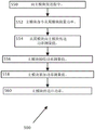
Referring now to FIG. 3, a method 301 for detecting series and/or parallel arcing is illustrated. The central controller 204 may be configured to measure one or more parameters, such as the power received by the load 250 (step 300). The module 202 may be configured differently, such as to measure the power of one or more panels 200 (step 302). The module 202 may be configured differently. In one embodiment, it communicates data representative of the measured power of one or more panels 200 to controller 204 via wireless or power line communication. The controller 204 calculates the difference between the power generated at the panel 200 and the power received at the load 250 (step 304). In the example, if the difference calculated in step 304 indicates that the power generated at the panel 200 may be greater than the power received at the load 250 according to predefined criteria (step 306), then an alarm condition for potential arcing may be set (step 308). Otherwise, in the example, arc detection continues with step 300.
Referring now to FIG. 4, an exemplary method 401 for detecting series and/or parallel arcing is shown. In the method according to the example, the central controller 204 measures (step 400) a Root Mean Square (RMS) noise voltage of the load 250. The module 202 may then measure (step 402) the Root Mean Square (RMS) noise voltage of one or more panels 200. The module 202 may be configured to transmit data representing the Root Mean Square (RMS) noise voltage of the panel 200 to the controller 204 via wireless or power line communication.
The one or more controllers may be configured to compare the noise voltage at the panel 200 to the noise voltage at the load 250 (step 404), for example, by calculating a difference between the noise voltage measured at the panel 200 and the noise voltage measured at the load 250. In the example, if the difference calculated in step 404 shows that the noise voltage measured at the panel 200 may be greater than the noise voltage measured at the load 250 according to one or more predefined criteria (step 406), then an alarm condition for potential arcing may be set (step 408).
Additionally for the example, comparing (step 404) may also involve comparing RMS noise voltage levels of the panel 200 and/or the load 250 previously stored in the memory of the controller 204 at different times (e.g., immediately after installation of the power generation system 201). In the example, the previously stored RMS noise voltage levels for both the panel 200 and the load 250 are stored in the memory of the controller 204 in the form of a look-up table. The look-up table has RMS noise voltage levels of both the panel 200 and the load 250 at different times of the day, days of the week, or times of the year, for example, which may be compared to the currently measured RMS noise voltage levels of both the panel 200 and the load 250.
In the exemplary example, if the comparison of the measured load 250 Root Mean Square (RMS) noise voltage data to the measured panel 200 Root Mean Square (RMS) noise voltage data may be greater than a particular threshold value of the RMS noise voltage difference (step 406), an alarm condition for potential arcing may be set (step 408), otherwise arc detection continues with step 400.
Referring now to fig. 5a, a power generation circuit 501a is shown in accordance with an embodiment of the present disclosure. In the power generation circuit 501a, the output of the panel 200 is connected to the input of the module 202. The output of the panel 200 may be configured to be directed to a dieBlock 202 provides a DC power input (P) IN ). The module 202 may include a direct current (DC-to-DC) switching power converter such as a buck circuit, a boost circuit, a buck-boost circuit, a configurable buck or boost circuit, a cascaded buck and boost circuit with configurable bypass to disable buck or boost stages, or any other DC-DC converter circuit. The output voltage of the module 202 may be labeled V i 。
The outputs of module 202 and module 202a may be connected in series to form a series string 520. The two strings 520 may be shown as being connected in parallel. In one string 520, it is shown that an arc voltage (V) may be being generated in series in the string 520 A ) The case (1). The load 250 may be a DC to AC inverter. The controller 204 may be attached to a load 250. The controller 204 optionally measures the voltage (V) across the load 250 through the current sensor 206 T ) And the current of the load 250. The current sensor 206 may be attached to the controller 204 and coupled to a power line connection of the load 250.
Depending on the solar radiation on the panel 200, in the first case, some of the modules 202 may operate to convert power on the input, providing a fixed output voltage (V) for the modules 202 i ) And output power, which may depend on the current flowing in the string 520. The current flowing in the string 520 may be related to the irradiance level of the panel 200, e.g., the greater the irradiance, the greater the current in the string 520, and the greater the output power of the module 202.
In the second case, the module 202 may operate to convert power on the input to the same power on the output, e.g., if 200 watts at the input of the module 202, the module 202 attempts to have 200 watts at the output as well. However, since the modules 202 may be connected in series in the string 520, the current flowing in the string 520 may be the same according to kirchhoff's law. The same current flowing in the string 520 means the output voltage (V) of the module i ) Should be changed to ensure that the power at the output of the module 202 may be the same as the power at the input of the module 202. Thus, in the example, as the string 520 current increases, the output voltage (V) of the module 202 i ) ReducingSmall, or as string 520 current decreases, the output voltage (V) of module 202 i ) Increasing to a maximum value. When the output voltage (V) of the module 202 i ) When increasing to a maximum, the second case may be similar to the first case, since the output voltage (V) is i ) Can now be effectively fixed.
The modules 202 in the string 520 may have a master/slave relationship, with one of the modules 202a configured as a master module and the other modules 202 configured as slave modules.
Since the current may be the same throughout the string 520 in the example, the master module may be configured to measure the current of the string 520. The modules 202 optionally measure their output voltage V i So that the total string power can be determined. In the example, the output voltage of the slave module 202 may be measured and communicated by wired communication or by power line communication, such as to the master unit 202a, so that a single telemetry from the module 202a to the controller 204 may be sufficient to communicate the output power of the string. The master module 202a in the string 520 may be configured differently, such as communicating with other slave modules 202 for controlling the slave modules 202. In the example, master module 202a may be configured to receive a "keep alive" signal from controller 204, which may be communicated to slave module 202. An optional "keep alive" signal sent from the controller 204, transmitted by wireless communication or by power line communication, may or may not be present. The presence of the "keep alive" signal may cause module 202 to run continuously and/or continuously through master module 202 a. The absence of a "keep alive" signal may cause module 202 to cease operation and/or to cease operation by master module 202a (i.e., current ceases to flow through string 520). Multiple "keep alive" signals, each having a different frequency corresponding to each string 520, may be used so that a particular string 520 may be brought to a stop producing power, where arcing conditions may exist while other strings 520 continue to produce power.
Referring now also to fig. 5b, a method 503 for comparing load power to string power is shown. In step 500, the power of one or more strings 520 may be measured. In step 502, the load 250 power may be measured using the central controller 204 and the sensor 206. The measured load power and the measured string power may be compared in step 504. Steps 500, 502 and 504 may be mathematically represented by the equation eq.2 (assuming a string 520), in this example, with reference to fig. 5a, as follows:
V T I L =∑P IN -V A [I L ]I L +∑V i I L Eq.2,
wherein:
V A [I L ]as current I L A functional arc voltage;
V T I L power of the load 250;
ΣP IN when the module 202 is operational, the output voltage (V) of the module is enabled i ) Varying to ensure that power at the output of module 202 can be matched to power (P) at the input of module 202 IN ) When the same, the power output of module 202; and
ΣViI L has a fixed voltage output (V) i ) And/or when the string 520 current is reduced sufficiently to cause the output voltage (V) of the module 202 to decrease i ) At increasing maximum output voltage level (with variable output voltage V) i Of) the power output of the module 202. In all cases, the maximum output voltage level value (V) i ) And a fixed voltage output (V) i ) May be previously configured to be the same in the power generation circuit 501 a.
By power (V) delivered to the load 250 T xI L ) Subtracting the sum of the power of the string 520(∑ P) IN +ΣV i I L ) The difference, the string power of the string 520 and the power (V) delivered to the load 250 can be achieved T xI L ) A comparison between them. If the difference is likely to be less than the predefined threshold (step 506), the measurement of the power available to the string 520 (step 500) and the load 250 (step 502) continues. In decision block 506, if the difference may be greater than a previously defined threshold, an alarm condition may be set and a series arc condition may be occurring. The condition of series arcing typically results in a "keep alive" signal from the controller 204 to module 202, this causes module 202 to shut down. Module 202 shutdown may be the preferred way to stop series arcing in string 520.
Referring now to FIG. 5c, method step 500 (shown in FIG. 5 b) of measuring the power of string 520 is shown in more detail. The central controller 204 may send an instruction to the main module 202a through power line communication (step 550). Master module 202a may measure the string 520 current as well as the voltage at the output of master module 202a and/or the voltage and current at the input of master module 202a to give the output power and input power, respectively, of module 202 a. The master module may command (step 552) the slave modules 202 in the string 520 to measure the output voltage and string 520 current and/or the input voltage and current of the module 202 to give the output power and input power, respectively, of the module 202. Slave module 202 may then be configured to transfer (step 554) the input power and output power measured in step 552 to master module 202 a. Master module 202a receives (step 556) the power measurement transmitted in step 554. Master module 202a then accumulates the received power measurement with the power measurement made by master module 202a according to equation Eq2 (step 558). According to the equation Eq2, Sigma P IN When the module 202 is operational, the output voltage (V) of the module is enabled i ) Varying to ensure that power at the output of module 202 can be matched to power (P) at the input of module 202 IN ) When the same, the power output of module 202; sigma ViI L Has a fixed voltage output (V) i ) And/or when the string 520 current is reduced sufficiently to cause the output voltage (V) of the module 202 to decrease i ) At increasing maximum output voltage level (with variable output voltage V) i Of) the power output of the module 202. In all cases, the maximum output voltage level value (V) i ) And a fixed voltage output (V) i ) May be previously configured to be the same in the power generation circuit 501 a. The power measurement accumulated in step 558 may then be transmitted by master module 202a to central controller 204 (step 560).
Referring now to FIG. 5d, a method 505 for series arc detection is shown. A first differential power result 508 appears in circuit 501a, the load current I L Now labeled as Current I 1 The voltage across the load 250 is V T (as shown in fig. 5 a). The first differential power result 508 may be generated as a result of performing the method 503 (shown in fig. 5 b) with reference to fig. 5a and equation eq.3 (below). Equation Eq.3 is as follows:
V T I 1 =∑P IN -V A [I 1 ]I 1 +∑V i I 1 Eq.3,
wherein:
V A [I 1 ]as current I 1 A functional arc voltage;
V T I 1 power of the load 250;
ΣP IN when the module 202 is operational, the output voltage (V) of the module is enabled i ) Varying to ensure that power at the output of module 202 can be matched to power (P) at the input of module 202 IN ) When the same, the power output of module 202; and
ΣV i I L has a fixed voltage output (V) i ) And/or when the string 520 current is reduced sufficiently to cause the output voltage (V) of the module 202 to decrease i ) At increasing maximum output voltage level (with variable output voltage V) i Of) the power output of the module 202. In all cases, the maximum output voltage level value (V) i ) And a fixed voltage output (V) i ) May be previously configured to be the same in the power generation circuit 501 a.
The impedance of the load 250 may optionally be adjusted under the control of the central controller 204 (step 510). Generally, if the load 250 is an inverter, the controller 204 adjusts the input impedance of the load 250 by changing the control parameters of the inverter. Due to ohm's law, a change in the input impedance of the load 250 causes the voltage across the input of the load 250 to change. As shown, the voltage across the load 250 (V) in the circuit 501a is adjusted due to the input impedance of the load 250 T ) The amount of Δ V can thus be varied. The voltage across the load 250 may now be V T + Δ V, and load 250 current (I) L ) May now be I 2 。
The method 503 (shown in fig. 5 c) is performed again based on the adjusted input impedance of the load 250 obtained in step 510, as a result of which a second differential power result 522 can now be generated. The second differential power result 522 may be mathematically represented by the equation Eq.4, as follows:
(V T +ΔV)I 2 =∑P IN -V A [I 2 ]I 2 +∑V i I 2 Eq.4,
wherein:
V A [I 2 ]as current I 2 A functional arc voltage;
(V T +ΔV)I 2 power delivered to the load 250;
ΣP IN when the module 202 is operational, the output voltage (V) of the module is enabled i ) Varying to ensure that power at the output of module 202 can be matched to power (P) at the input of module 202 IN ) When the same, the power output of module 202; and
ΣV i I L has a fixed voltage output (V) i ) And/or when the string 520 current is reduced sufficiently to cause the output voltage (V) of the module 202 to decrease i ) At increasing maximum output voltage level (with variable output voltage V) i Of) the power output of the module 202. In all cases, the maximum output voltage level value (V) i ) And a fixed voltage output (V) i ) May be previously configured to be the same in the power generation circuit 501 a.
The first differential power result 508 may be compared (step 524) to the second differential power result 522, for example, by the controller 204 subtracting the first differential power result 508 from the second differential power result 522 to obtain a difference. The difference may be expressed by equation Eq.5, which may be the result of subtracting equation Eq.3 from equation Eq.4, as follows:
V T I 1 -(V T +ΔV)I 2 =V A [I 2 ]I 2 -V A [I 1 ]I 1 +∑V i (I 1 -I 2 ) Eq.5
whereby the output power (P) summed up by each block 202 of the circuit 501a can be cancelled IN )。
The equation eq.5 may be rearranged by the controller 204 by performing a modulo operator function on the equation eq.5 to obtain the arc coefficient α as shown in equation eq.6.

Where the arc coefficient a is shown in eq.7.

The controller 204, for example, may be configured to calculate the coefficient α according to the above formula and the measured value. The non-zero value of the arc coefficient α shown in equation 7 causes an alarm condition to be set (step 528), otherwise another first differential power result 508 may be generated (step 503). The series arcing condition typically causes the controller 204 to remove the "keep alive" signal, causing the module 202 to shut down. Module 202 shutdown may be the preferred way to stop series arcing in string 520.
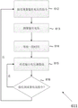
Referring now to fig. 6a, a flow (e.g., method) 601 for detecting an arc is shown. In one or more embodiments, the method 601 shown in fig. 6a and/or one or more steps thereof may be performed by one or more computing devices, such as a controller computing device, which may be similar or identical to the controller 204 of fig. 2. For example, a computing device (e.g., controller, etc.) may be and/or include an analog circuit, a microprocessor, a Digital Signal Processor (DSP), an Application Specific Integrated Circuit (ASIC), and/or a Field Programmable Gate Array (FPGA). The controller may communicate with one or more modules similar or identical to module 202 and may use one or more communication methods, such as Power Line Communication (PLC), wireless communication (e.g., cellular communication, WiFi), and the like TM 、ZigBee TM 、Bluetooth TM Or alternative protocols) and/or acoustic communications. In some embodiments, one or more of the methods 601Aspects or steps may be performed by a master module controller, such as a controller that may be part of a master module (e.g., module 202 a).
For illustrative, non-limiting purposes, the method 601 will be described as being performed by the controller 204, and the controller 204 may be in communication with the module 202 (e.g., in communication with the module 202 including communication and/or control devices), as shown in fig. 2, and described with fig. 2. The method 601 may be similarly used for different arrangements of power modules, controllers, and other devices. According to some embodiments, the controller 204 may be included in and/or in communication with a device such as a power module (e.g., power module 202), a combiner box, a photovoltaic inverter, and the like. According to some arrangements, the controller 204 may be connected to and/or wirelessly coupled to the power module and/or other PV devices. According to some arrangements, the controller 204 may be a remote server configured to remotely control the PV power system. Any disclosed steps of fig. 6a (and/or associated descriptions herein) may be omitted, performed in a manner other than that recited, repeated, and/or combined.
The method 601 may begin at step 602, where a computing device (e.g., controller 204) may command a plurality of string-connected modules (e.g., modules 202) to measure one or more electrical parameters (e.g., through one or more communication methods disclosed herein). These electrical parameters may be module-based parameters (e.g., module output voltage V) i ). In some embodiments, the instructions may indicate a time or timestamp at which the module may begin measuring the output voltage, and/or may indicate a time interval at which the module may begin measuring the output voltage after an event, such as after receiving the instructions from the controller 204.
In some embodiments, the obtaining of the measured values of the electrical parameter may be synchronized, which may be used to facilitate summing of the measured parameters. For example, the controller 204 may send instructions to synchronize voltage measurements that may be used to determine the total string voltage by summing one or more individual time-synchronized voltage measurements.
In another example, inThe instruction sent at step 602 may include having the module (e.g., in a series string of modules) instantaneously couple to the output voltage V i Sampling or sampling the output voltage immediately after the module receives the instruction. According to some aspects, the command sent at step 602 may be at a speed comparable to the speed of light (i.e., 3 · 10) 8 m/sec) or at some other speed. As an illustrative numerical example, if the communication between the controller 204 and the module 202 is at about one-third of the speed of light (e.g., about 10) 8 m/sec) and the maximum communication path distance between any two modules 202 in the plurality of serially connected modules 202 is 100m, the respective points in time at which each pair of respective modules 202 receives the instruction may differ by no more than about If each of the plurality of string-coupled
 modules 202 measures voltage immediately upon receiving the instruction, the plurality of measurements may be considered substantially simultaneous (i.e., corresponding to points in time that are sufficiently close for the sum of the measurements to accurately represent the total string voltage at a single point in time).
In some embodiments, the instructions sent at step 602 may include information to synchronize the transfer of measurements, such as voltage measurements obtained by module 202. For example, the instructions may instruct one or more of the modules 202 of fig. 5a to measure the output voltage 10 seconds after receiving the instructions, may instruct a first module (e.g., 202a) to transmit the measured output voltage 1 second after measuring the output voltage (or a corresponding number of clock cycles depending on the clock that may be included in the module), may instruct a second module 202 to transmit the measured output voltage two seconds after measuring the output voltage, and so on. In this manner, each of the plurality of modules 202 may measure the module output voltage at substantially the same time, but may transmit the measurement at a different time relative to another module 202, which may reduce the likelihood of simultaneous transmissions and the likelihood of data being potentially lost (e.g., dropped packets).
In some embodiments, the instruction sent at step 602 may not command module 202 synchronize the measurement transmissions, but may instruct one or more of the modules 202 to wait a random period of time before transmitting the measurement. The likelihood of overlapping transmissions may be lower if a wide time window is allowed for the transmission. As an illustrative numerical example, each module 202 is capable of transmitting a measurement within 100 milliseconds. If forty modules 202 transmit measurements during a 5 minute time window and each module 202 broadcasts measurements at random times during the 5 minute time window, then the following is true There will be no overlap of two measurement transmissions and each transmission can be received. According to some aspects, the probability of no two transmissions overlapping may be estimated, determined, or calculated by Eq.8, Eq.8 being as follows:

where N denotes the number of transmit modules 202, and the transmit time and the size of the window may be selected to obtain the desired probability of non-overlapping transmissions, N × transmission _ time < (window _ size). According to some aspects, preferred configurations may include: transmission _ time < < window _ size.
It should be understood that the elements of measurement synchronization disclosed with respect to method 601 may be similarly applied to other methods disclosed herein. For example, one or more steps of the method 500 shown in fig. 5c may use the measurement and/or transmission synchronization described with respect to fig. 6 a.
In some embodiments, step 602 may not be implemented, and each module 202 in the string of modules 202 may independently measure an output voltage measurement without receiving instructions from the controller 204. For example, each module 202 may measure the output voltage every several minutes (e.g., every minute, every five minutes, or every fifteen minutes, etc.).
In some embodiments, each module 202 may measure a Direct Current (DC) output voltage and/or an Alternating Current (AC) output voltage. For example, each module 202 may include a DC-to-DC converter that outputs a DC output voltage (or other parameter such as current), and each module 202 may measure the output DC voltage. According to some embodiments, each module 202 may include a DC-to-AC converter (e.g., an inverter, a microinverter, etc.) that outputs an AC output voltage, and each module 202 may measure the output voltage (or other parameter such as current).
At step 603, the controller 204 may receive a measurement (e.g., an output voltage measurement) from one or more of the plurality of modules 202. In some embodiments, each module 202 may communicate a tag (e.g., a unique code, an ID code, etc.) with the measurement. According to some aspects, the controller 204 may compare each unique tag to a list of tags (e.g., a list stored in a non-transitory computer-readable memory that may be coupled to and/or included in the controller) to determine whether a voltage measurement has been received from a particular module. According to some aspects, a list of tags (i.e., method steps not explicitly indicated in fig. 6 a) may be obtained prior to step 602. For example, the steps may include identifying one or more of the plurality of modules and storing a unique tag associated with each module.
Optionally, if one or more measurements may not be correctly received by the controller 204, the controller 204 may command one or more modules 202 to retransmit the measurements. For example, if measurements are not received from the first module 202 and the second module 202, in some embodiments, the controller 204 may command all or some of the modules 202 to retransmit the measurements, and/or in some embodiments, the controller 204 may request retransmission only from the first module 202 and/or the second module 202.
In another embodiment, one or more modules 202 may initially (e.g., in response to step 602) transmit module output voltage measurements twice, which may provide redundancy and prevent measurement loss (e.g., due to overlapping transmission times). For example, with respect to equation 8 above, if each measurement is transmitted twice, if a measurement loss occurs, the probability that two measurements transmitted by a single module 202 are lost at the same time is very small, thereby increasing the probability that the controller 204 receives at least one measurement from each module 202.
At step 604, the controller 204 may determine whether one or more timestamps associated with the measurements received at step 602 indicate about the same time. For example, the controller 204 may evaluate timestamps associated with one or more received voltage measurements to determine that the measurements received at step 603 indicate about the same time at which the respective measurements are likely to be obtained. For example, if the two timestamps indicate that the difference in time is small or negligible (e.g., milliseconds), the controller 204 may determine that the measurements are likely to be taken at about the same time. In another example, if the two timestamps indicate that the difference in time is large or non-negligible (e.g., seconds, tens of seconds or minutes, or greater), the controller 204 may determine that the measurements were taken at different times (i.e., not at about the same time). If all of the measurements, or all of the measurements of interest, are determined to be taken at or about the same time, the controller 204 may proceed to step 605, which will be discussed in more detail below. If all of the measurements, or all of the measurements of interest, are determined not to have been obtained at or about the same time, the controller 204 may proceed to step 610 and/or return to step 602.
In some embodiments, the controller 204 may perform step 610 before returning to step 602. At step 610, one or more alternative arc detection steps and/or methods may be utilized. For example, at step 610, one or more voltage measurements that may have been received from multiple modules 202 and that may have been determined to be measured at different times may be used by the controller 204 to determine or estimate a corresponding voltage for each module at a particular time (e.g., according to the method 650 of fig. 6e described in more detail below). According to some aspects, the controller 204 may proceed to step 605 and may use the voltage value determined in step 610. According to some aspects, at step 610, the controller 204 may compare the received voltage measurement to previously measured voltage measurements and may determine that an arcing condition may exist based on one or more module voltages exhibiting a trend indicative of an arcing condition (e.g., measured voltages rising or falling over time).
At step 605, controller 204 executing method 601 may calculate a sum of one or more output voltage measurements received at step 603, which may be expressed as Σ Vi for voltages, but may be expressed as another sign for other parameters such as current, power, etc. According to some aspects, Σ Vi may indicate a voltage (e.g., a total voltage) across a string (e.g., 520) that includes multiple serially connected modules 202 or may indicate a voltage across a portion of a string.
At step 606, the controller 204 (or other device or entity) may compare Σ Vi to reference parameters (e.g., voltage, current, power, etc.). For example, the reference may be a single reference voltage or multiple reference voltages. In some embodiments, the reference may be the sum Σ Vi of the voltages previously obtained by performing the method 601 (e.g., the value saved at step 608, which is discussed in more detail below). In some embodiments, the reference may be a series of voltages measured over time (e.g., ten values of ∑ Vi obtained by previously performing the method 601). In some embodiments, the reference may be a voltage measured in the power generation circuit (e.g., 501a) and/or at a different location in the power generation system (e.g., 201). In one example, the reference may be a voltage measured at the input of the load 250 of fig. 5 a.
At step 607, the controller 204 may determine whether the comparison performed at step 606 indicates an arcing condition. For example, in some embodiments, the controller 204 may compare Σ Vi to a reference voltage measured at the input of the load 250, which may be denoted as V _250, and may determine that an arcing condition may exist if Vdiff ∑ Vi-V _250> Vthresh, where Vthresh may be selected as the minimum difference voltage that may indicate an arcing condition. In some embodiments, Vthresh may be about 1 volt. In some embodiments, Vthresh may be less than or greater than about 1 volt. Referring back to fig. 2, in the case of the series arc 106, the voltage drop across the series arc 106 (which may be referred to as Varc) may start at a low voltage (e.g., tens or hundreds of millivolts), and over time, Varc may increase, such as to several volts (e.g., such as to 10 volts, 100 volts, or even higher). According to some aspects, Varc may not be measured by module 202, but Varc may be reflected by V _250 (i.e., the voltage measured at the output of load 250). For example, Varc corresponding to series arc 106 may not be included in the voltage measurements obtained by module 202, but the voltage measurements obtained at the input of load 250 may include a portion corresponding to Varc. By selecting the appropriate Vthresh, the series arc 106 may be detected before a dangerous condition occurs.
In some embodiments, Vthresh may be selected based on historical data. For example, Vthresh may be selected based on differential voltages measured in the power generation system under one or more arcing conditions. In some embodiments, Σ Vi may be compared to a previously measured voltage and/or a differential voltage. For example, the method 601 is performed ten times, once every three minutes, ten different Σ Vi results and ten differential voltage results Vdiff may be generated. If the ten Vdiff results (e.g., Vdiff1, Vdiff2 … … Vdiff10) indicate a trend (e.g., differential voltage increases over a period of time) and the newly obtained Vdiff11 result continues the trend, the controller 204 may determine that an arcing condition may exist.
If the controller 204 determines at step 607 that an arcing condition may not exist, the controller 204 may return to step 602 and, after a period of time, restart the method 601. In some embodiments, the controller 204 may proceed from step 607 to step 608 and save the calculated values Σ Vi and Vdiff into memory for future use, and then return from step 608 to step 602. In some embodiments, at step 608, the controller 204 may save additional data, such as individual measurements received from the module (e.g., module 202), for future reference and analysis. According to an embodiment, the measurements saved at step 608 may be used at step 653-654 of method 650, as shown in fig. 6 e.
If the controller 204 determines at step 607 that an arcing condition may exist, the controller 204 may proceed to step 609 and set an alarm condition. Setting an alarm condition may result in various security protocols being generated.
For example, the controller 204 (or other device) performing the method 601 may be coupled to a wired and/or wireless network/internet/intranet, and/or any number of end-user devices, such as computers, smart phones, tablets, and/or other devices, such as a server that may be located at one location, such as a network operations center and/or a power generation monitoring center. These devices may be used to generate warnings to warn of dangerous conditions and/or take action to weaken or shut down certain portions of the power generation circuit 501 a. For example, the warnings may be audible and/or visual. According to some aspects, the warnings may be beeps, tones, lights, whistling, LEDs, or high lumen LEDs. These alerts may be located or initiated in a premises, such as in a home, building, vehicle, aircraft, solar farm, on a roof, in the power generation circuit 501a, etc. In one example, the alert may be centralized (such as in a server) and/or distributed to end-user devices (e.g., computers, smart phones, and/or tablets). These warnings may be displayed on displays coupled to, attached to, and/or embedded within various components of the power generation circuit 501a (e.g., disconnectors, switches, PV cells/arrays, inverters, micro-inverters, optimizers, residual current devices, meters, circuit breakers, mains and/or junction boxes, etc.). The alert may be variously coupled to the user or installer's cell phone and/or other device (e.g., personal device, computing device, etc.) to make the user aware that the circuit is in a hazardous condition and/or alert the user when the user may be approaching or near the circuit in a hazardous condition. The alert may be coupled to or otherwise associated with GPS coordinates, and/or generated in response to a device (e.g., a smartphone, a tablet, etc.) moving in a location approaching a hazardous condition. The measurements and/or summed measurements ∑ Vi sent by the module 202 may be analyzed locally and/or sent to another device for further analysis, storage, and review.
In some embodiments, step 609 may include shutting down power production of the power generation system in response to the arcing condition. According to some aspects, if at step 607, the controller 204 determines that an arcing condition may exist, the controller 204 may repeat one or more steps of the method 601, which may reduce the risk of a "false alarm" and/or reduce the frequency of shutting down the power generation system due to one or more inaccurate or unreliable measurements or due to measurement noise. According to some aspects, control 24 may repeat one or more steps of method 601 more than once. According to some aspects, the performance and/or repetition of the steps of method 601 may be performed in rapid succession (e.g., one second apart, several seconds apart, etc.), or may be separated by longer periods (e.g., minutes apart, hours apart, etc.). In some embodiments, an alarm condition may be set only when two or more executions of the method 601 indicate an arcing condition. According to some aspects, the method 601 may end at any time and/or after any step.
In some embodiments, the method 601 may be performed by a controller 204 coupled to a plurality of PV strings. Controller 204 may perform method 601 with respect to each PV string (e.g., if ten PV strings are coupled to controller 204, controller 204 may perform method 601 ten times every 5 minutes, with each execution of method 601 applying to a different string). In some embodiments where the controller 204 is coupled to a plurality of PV strings, step 609 may further include indicating which string coupled to the controller 204 triggered the alarm condition (i.e., which string may have experienced an arcing condition).
Referring now to FIG. 6b, a method is shown, according to one embodiment. The method 611 may be performed by a controller or other computing device, such as a device configured to control a module (e.g., a photovoltaic power device, such as a DC-DC converter, a DC-AC micro-inverter, a disconnector, a monitoring device, and the like). For example, the computing device (e.g., controller, etc.) may be and/or include analog circuitryA microprocessor, a Digital Signal Processor (DSP), an Application Specific Integrated Circuit (ASIC), and/or a Field Programmable Gate Array (FPGA). The controller may control one or more modules similar or identical to module 202, and may use one or more communication methods, such as Power Line Communication (PLC), wireless communication (e.g., cellular communication, WiFi), and the like TM 、ZigBee TM 、Bluetooth TM Or alternative protocols) and/or acoustic communications.
For illustrative, non-limiting purposes, the method 601 will be described as being performed by the controller 804 of fig. 8a (which may be similar or identical to the controller 204 and will be discussed in more detail below), which may be a feature of the power module 802 that is similar or identical to the module 202 of fig. 2. The controller 804 performing the method 611 may communicate with the second controller 204 performing the method 601, for example using Power Line Communication (PLC), wireless communication or acoustic communication. For example, the method 611 may be performed by a controller included in the power module, and the method 601 may be performed by a controller included in a PV inverter in electrical communication with the power module. The controller 804 may measure one or more sensors that control electrical parameters used to measure and/or associate with the module, such as input and/or output voltage, current, power, solar irradiance, and/or temperature, for example, the sensor/sensor interface 805 of fig. 8a, which may be similar or identical to the sensor 206 and will be discussed in more detail below. If the sensor/sensor interface 805 comprises voltage sensors, the voltage sensors may be placed in parallel to detect a voltage at an input or output of the module 802 of FIG. 8a, for example.
At step 612, the controller 804 may receive instructions (e.g., from the second controller 204 performing step 602 of the method 601) to measure parameters (e.g., input and/or output voltages, currents, power, solar irradiance, and/or temperature) of an associated module (e.g., the module 202 of fig. 2).
At step 613, the controller (e.g., controller 804) may command the associated sensor to measure the output voltage of the module (e.g., module 202), and the voltage measurement may be saved to memory (e.g., memory device 809 of FIG. 8a, discussed in more detail below). In some embodiments, controller 804 may receive (e.g., at step 612 or at other times) an instruction that may indicate a certain time for performing one or more aspects of step 613. For example, the instruction received at step 612 may instruct the controller 804 to measure the output voltage at a time (e.g., at 1:00:00pm), or may instruct the controller to measure the output voltage after a predetermined period of time (e.g., 3 seconds after receiving the instruction).
At step 614, the controller 804 may determine a period of time before the controller 804 commands the communication device 806 to transmit the voltage measurement at step 615. In some embodiments, the instruction received at step 612 (or at other times) may indicate a time at which step 615 should be performed, which may reduce the probability of multiple controllers transmitting simultaneously. For example, the instruction received at step 612 may indicate that the output voltage may be delivered at 1:00:01pm (i.e., one second after measurement). In some embodiments, the controller 804 may select a period of time (e.g., a random or pseudo-random period of time, etc.) to wait before transmitting. For example, the controller 804 may select (e.g., based on a uniform distribution) to wait a random period of time between 1 second and fifteen minutes before transmitting the voltage measurements.
At step 615, the voltage measurements are communicated to an associated controller (e.g., controller 204 executing method 601). In some embodiments, the voltage measurements may be transmitted with additional information, such as an Identification (ID) tag associated with the controller and/or a timestamp indicating the time/timestamp (or other description) of when the voltage measurements were obtained. In some embodiments, the voltage measurement may be transmitted more than once at step 615, which may increase the probability that the measurement will be received at least once by the receiving second controller.
At step 616, the controller 804 may receive an instruction to retransmit the voltage measurement, e.g., if communication has been lost and/or not received by another component, such as due to a transmission error, the controller 804 may retransmit the voltage measurement. If such an instruction is received, the controller 804 may loop back to step 615 and retransmit. If no such instruction is received, the controller 804 may return to step 612 and wait to receive additional instructions to measure the output voltage. According to some aspects, the method 611 may end at any time and/or after any step.
Referring now to fig. 6c, a data packet 630 is illustrated in accordance with one or more disclosed aspects. The data packet 630 may include one or more elements, such as a sender ID tag 632, a timestamp 633, and one or more measurements 634. The sender ID tag 632 may indicate the identity (e.g., unique ID) of the associated controller or module that sent the data packet 630. Measurements 634 may include one or more measurements obtained by sensors at the module (e.g., 202 or 802), such as voltage, current, power, temperature, and/or irradiance measured at or near the module (e.g., module 202). The timestamp 633 may indicate the time at which the measurement 634 was obtained and/or measured. If several measurements are taken at different times, several time stamps 633 may be included for the respective measurements. In some embodiments (e.g., in cases where the packet may be received by a device that is not intended as an end recipient), the packet may include a target ID tag 635 corresponding to the intended or subsequent recipient. In some embodiments, the packet may include a header 631 of metadata about the packet contents and may include a Cyclic Redundancy Check (CRC) portion 636 that may provide enhanced data integrity.
According to some aspects, the data packet 630 may be transmitted at step 615 of the method 611 and/or may be received at step 603 of fig. 6 a. The timestamp 633 of the data packet 630 may be read and/or processed at step 604 (e.g., by the controller 204) to verify that the data packet 630 and one or more other data packets were received at approximately the same time. According to some aspects, the data packet 630 may include a measurement 634 that may be used at step 605 (e.g., by the controller 204) to calculate a sum of voltages (or other parameters) measured by the plurality of modules (e.g., 202).
Referring now to FIG. 6d, a methodology for arc detection is illustrated in accordance with one or more disclosed aspects. According to some aspects, step 610 of method 601 may include one or more steps of method 640. The method 640 may be used by a controller (e.g., the controller 204) to detect or determine an arcing condition by utilizing one or more parameter measurements (e.g., voltage measurements) that may not be measured and/or obtained at about the same time. For example, one measurement may be obtained at a first time and a second measurement may be obtained at a second time.
At step 641, the controller (e.g., 204) executing the method 640 can evaluate a set of timestamps 633 corresponding to respective measurements 634 of a set of parameter measurements 634 (e.g., voltage measurements, current measurements, etc.). For example, the controller may read the plurality of time stamps 633 and determine that the time stamps 633 may not be about the same (e.g., the time stamps 633 may indicate a plurality of points in time that differ by seconds, tens of seconds, minutes, or hours).
At step 642, the controller 204 may select the reference timestamp ts. In some embodiments, the reference timestamp may be one of a set of timestamps 633 (e.g., the earliest timestamp, the latest timestamp, an intermediate timestamp, or a median timestamp, etc.). In some embodiments, the reference timestamp ts may not correspond to one of the set of timestamps 633 (e.g., may be an average of two or more timestamps in the set of timestamps or may be a random time within a range of timestamps).
At step 643, the controller 204 may determine a plurality of voltage estimates, calculations, or approximations corresponding to the voltage measured at the reference timestamp ts. For example, if the controller 204 evaluates that the voltage V corresponds to at step 641 1 [t1],V 2 [t3],V 3 [t3]And V 4 [t4]Time stamps t1, t2, t3, and t4 (e.g., voltages measured at four different modules 202), then at step 643 controller 204 may determine the voltage And
And (i.e., the voltage at the four
 modules 202 at the timestamp ts). According to some aspects, the controller may determine these voltage estimates by interpolation, regression analysis, or the like. Aspects of step 643 are discussed in more detail below with respect to FIG. 6 e.
At step 644, the controller (e.g., 204) executing the method 640 may calculate a sum of the output voltage measurements estimated or determined at step 643, which may be denoted as ∑ Vi. Σ Vi may indicate the total voltage across a string (e.g., 520) or a portion of a string 520 that includes multiple serially connected modules 202.
Referring now to fig. 6e, a method for estimating a parameter (e.g., voltage) at a particular timestamp is shown, according to an embodiment. The method 650 may be used to estimate or determine the voltage drop at the reference timestamp, e.g., as in step 643 of method 640 shown in fig. 6 d. At step 651, the total voltage to be estimated (e.g., V) 1 [ts],V 2 [ts]Etc.) may be initialized by the controller 204 to an "unexesting" state or an "coarsely estimated" state. For example, the controller 204 may identify one or more voltages that may be used by the controller 204 in determining an arc condition.
At step 652, the controller 204 may select the unexstimated voltage V i (e.g., V) 1 ) For estimation.
Estimating may include, for example, direct calculation, probabilistic calculation, lookup, and/or receiving (e.g., via wired or wireless communication) estimated or determined values.
At step 653, the controller 204 can load the previous measurements or acquisitions (e.g., perform the method in the past)Measured at step 608 of method 601 during 601) V i Is measured. For example, the controller may load k V i Where k is a positive integer. In which V is i In systems that may change slowly and/or in a substantially predictable manner, the parameter k may be small, e.g., k may be 1, 2, or 3. According to some aspects, for ease of annotation, the time period elapsed between the jth previous voltage measurement and the reference timestamp ts may be referred to as Δ t j Wherein j is a positive integer less than or equal to k.
At step 654, the controller 204 may determine an approximate voltage V i [ts]The approximation value is represented as According to some aspects, the
 controller 204 may use the previous voltage measurements loaded at step 653 as input to a suitable estimation algorithm.
In some embodiments, the voltage V i May change slowly over time, and the voltage estimated at the reference timestamp may be I.e., k is 1, and the voltage at the reference time stamp may be determined to be the same as the last measurement value. In another embodiment, the voltage estimated at the reference timestamp may be calculated by fitting a previous voltage measurement to a linear curve, for example using the formula:

i.e., where k is 2. In which V is i In embodiments that may change rapidly or in a more complex manner, k may be greater than 2, and may be estimated using higher order polynomials, complex functions such as exponential or logarithmic functions, or statistical models Can be based on the estimation
 Statistical error in the process selects a threshold (e.g., a threshold used at
 step 601, 607 or step 646 to determine whether the difference between the sum of the voltages and the reference voltage is indicative of an arcing condition). For example, if the estimation can be performed with high accuracy A smaller threshold may be used (i.e., even a smaller difference between the sum of the voltages and the reference voltage may trigger an alarm condition indicating arcing). According to some aspects, a larger threshold may be used. According to some aspects, the voltage V may be adjusted i The labels are "determined", "estimated" or "approximate".
At step 655, the controller 204 may determine whether one or more (or all) voltages V have been estimated i . If the total voltage (or voltages of interest) has been estimated, the controller 204 may proceed to step 656 and provide the estimated voltage V i For further analysis (e.g., by the controller and/or computing device at step 644 of method 640). If it is determined that one or more voltages (i.e., one or more voltages of interest) may not be estimated, the method 650 may loop back to step 652. The method 650 may end at any time and/or after any steps.
Referring now to FIG. 6f, a methodology 660 for detecting arcing conditions in accordance with one or more disclosed aspects is illustrated. An apparatus (e.g., controller 204 or some other apparatus) may or may not perform one or more steps of method 660 as part of a different method (e.g., as step 610 of method 601). According to some aspects, a controller (e.g., 204) performing method 660 may detect a potential arcing condition by detecting a runaway trend in measured (e.g., currently measured, previously measured, etc.) parameter (e.g., voltage, current, power, and/or temperature) measurements. For illustrative purposes, one aspect of method 660 may be illustrated using voltage measurements.
At step 661, the controller 204 may receive (e.g., load from a memory component and/or receive via communication from another device) k (1, 2, 3, etc.) measured voltage measurements (e.g., measured at an input or output of the module 202, or at the load 250).
At step 662, the controller 204 may attempt to detect a trend in the voltage measurements. For example, the controller 204 may determine whether the voltage measurements exhibit an increase or decrease over time or remain substantially the same. According to some aspects, other trends may be detected using linear regression, non-linear regression, and the like. In one example, the voltage drop across the arc (e.g., arc 106) may always increase over time (e.g., due to melting of the conductor, which may increase the arcing air gap and thus the arcing voltage), which may cause the measured voltage (e.g., at module 202) to increase over time. The change in arcing voltage that may be observed over time may vary depending on one or more parameters, including, but not limited to, current flowing through the conductor where arcing may occur, conductor material, temperature, and other operational and environmental parameters. The controller (e.g., 204) performing the method 660 may be calibrated based on one or more of these parameters, which may be known or may be determined (e.g., experimentally estimated) based on the location of the component, device, or system performing the method 660.
According to an embodiment, the voltage drop across the arc may be through eq.9, as follows:

wherein, V arc May be full arc voltage, V c May be the voltage at the arcing contact point, d may be the arc air gap size, V d May be a parameter relating the voltage drop across the air gap to the size of the air gap d, I may be the current flowing through the arc, and I 0 May be a parameter (e.g., may depend on the conductor)Parameters of the material). According to some aspects, I may be measured by the module 202 and thus may be known, and d may grow over time (e.g., due to conductor melting), which may result in a change in the measured voltage, which may indicate an arcing condition.
As an illustrative numerical example, a system may have V c =15[V], I 0 1A, and 15A. The arc air gap size may increase at a rate of 0.1mm/sec, the arc voltage may increase at a rate of about 1V per 3 minutes, which may cause the voltage measured at the output of the
 module 202 to increase at a rate of 50mV per 3 minutes (e.g., in a case where the output impedance of the module 202 comprises about 5% of the total loop impedance "seen" by the arc), or may cause the voltage measured at the input of the module 202 to increase at a rate of about 500mV per 3 minutes (e.g., in a case where the arc is at the output of the module 202 and the input impedance of the module 202 is about 50% of the total loop impedance "seen" by the arc).
It should be understood that the exemplary values provided in the numerical example above are merely intended to indicate possible values corresponding to possible scenarios in one embodiment. The numerical values recited in the alternative systems and embodiments can vary, and the exemplary numerical values used above are not intended to be limiting in any way.
At step 663, the controller 204 may determine whether the voltage measurement loaded at step 661 indicates a trend, and if the measurement indicates a trend, whether the trend is controlled. An example of a controlled trend may be a start-up condition, for example, at the beginning of a day, where one or more modules 202 may actively increase the output voltage to provide increased power to load 250. Another example of a controlled trend may be a voltage reduction at the input of the module 202 caused by the module 202 performing Maximum Power Point Tracking (MPPT). Since the controlled trend may occur during normal system operation, if the controlled trend is detected (e.g., by associating the trend with a command issued by the control device or with an operational change in the module 202 and/or the load 250), the controller 204 may proceed to step 664, which may be similar or identical to step 608 of the method 601, and may save the measured values. If an uncontrolled trend is detected at step 663, the trend may indicate an arcing condition (e.g., an uncontrolled arcing condition), and the controller 204 may proceed to step 665, which may be similar or identical to step 609 of method 601, and may set an alarm condition. According to some aspects, method 660 may end at any time and/or after any step.
Referring now to fig. 7a, a Photovoltaic (PV) power generation system 701 is shown according to an exemplary embodiment. The PV power generation system 701 may include a plurality of PV generators. In the exemplary embodiment shown in fig. 7a, each PV generator may include a PV panel 700, which may be similar or identical to panel 200. In some embodiments, the PV generator may include individual PV cells, substrings of PV cells, one or more PV panels, and/or PV arrays. In some embodiments, the PV generator may be replaced or supplemented by one or more batteries, capacitors, supercapacitors, fuel cells, wind turbines, or other power generation or storage sources.
Each PV generator (in the case of fig. 7a, each panel 700) may be coupled to a power module 702 (e.g., 702a, 702b, 702c, etc., collectively referred to as "modules 702"). According to some aspects, power module 702 may be similar to or the same as module 202. Each module 702 may include input terminals and output terminals, which may be coupled to panel 700. Each module 702 may be configured to receive input power from panel 700 at input terminals and may be configured to provide output power at output terminals. The power provided by the plurality of modules 702 may be combined between a power bus and a ground bus. In the illustrative embodiment of fig. 7a, the output terminals of each module 702 are coupled in parallel between a power bus and a ground bus. Each module may apply Maximum Power Point Tracking (MPPT) to the associated panel 700, which may be used to extract increased power from the panel (e.g., at or near maximum power).
Fig. 7a illustrates a scenario where an arc 706 may occur between the output terminal of module 702c and the power bus. Representing the voltage between the power bus and the ground bus as Vpg, modules 702 may measure an output voltage of about Vpg, each module 702 may be coupled between the ground bus and the power bus due to the presence of the output terminal. Module 702c may measure an output voltage different from Vpg due to a voltage drop across arc 706. According to the methods disclosed herein, each module 702 may conventionally measure an output voltage across the respective output terminals of each module 702, and a comparison of the measured output voltages may indicate an arcing condition. In the illustrative example of fig. 7a, each module 702 (excluding module 702c) may measure an output voltage of about 300V, and since there is a 10V voltage drop across the arc 706, the module 702c may measure a voltage drop of about 310V.
In some embodiments, one or more of the modules 702 may measure voltage noise, and the voltage noise measurements obtained by each module 702 may be compared (e.g., by the controller 704). In some implementations, the voltage noise measurement obtained by the module 702c may be indicative of an arc 706. For example, if the voltage spectrum measured by module 702c includes significant high frequency components having magnitudes not found in other voltage measurements, one or more methods or steps disclosed herein may determine that the measurements may indicate that an arcing condition exists at or near module 702 c.
Referring now to FIG. 7b, a method 711 for detecting arcing is shown, in accordance with one embodiment. In some embodiments, the method 711 may be performed by a controller similar to or the same as the controller 704 of fig. 7 b. In some embodiments, method 711 may be performed by a master controller featuring module 702. For illustrative purposes, the method 711 will be described as being performed by the controller 704. Steps 712-714 may be similar to or identical to steps 602-604 of method 601, respectively. At step 715, a controller (e.g., 704) executing method 711 may compare the voltage measurements received at step 714 to one another. At step 715, the controller 704 may determine whether the measurements received from the modules differ (e.g., a voltage measurement differs from other measurements by more than 50mV, 500mV, or more than 1V, or a voltage noise measurement differs from other voltage noise measurements by tens of millivolts). According to some aspects, the voltage difference may be compared to some threshold value, which may be set by the controller or some other means. According to some aspects, the threshold may be a substantial difference between voltage measurements. According to some aspects, the threshold may be a ratio of voltages. For example, a voltage difference may be considered greater than a threshold value if the voltage difference is twice as large as the lower voltage measurement (corresponding to a threshold ratio of two), or ten times as large as the lower voltage measurement (corresponding to a threshold ratio of ten), or if the voltage difference is equal to the lower voltage measurement (corresponding to a threshold ratio of one). If it is determined at step 716 that an arcing condition is unlikely to exist, the method may proceed to step 718, where the controller 704 may save the measurements received at step 714 to memory. The controller 704 executing the method 711 may return to step 712, such as after a period of time (e.g., five minutes) has elapsed, to re-execute the method 711. In some embodiments, the method may return directly from step 716 to step 712 when past measurements may not be used for reference.
If it is determined at step 716 that an arcing condition may exist (e.g., when a voltage measurement is substantially different from other voltage measurements), the method may proceed to step 717, which may be similar to step 609 of method 601, and an alarm condition may be set. In some embodiments, the controller may repeat the method 711 and only proceed to step 717 (e.g., reducing the risk of a "false alarm") when additional repetitions indicate an arcing condition.
In some embodiments, the measurements recorded at step 718 may be used for reference during future executions of the method 711. For example, the first module 702 may always provide an output voltage measurement that is different from the output voltages of the other modules (e.g., due to a faulty sensor or due to a lossy element, such as a damaged wire). Steps 715 and 716 may be corrected to produce a constant or predictable measurement difference, and if the measurement difference changes continuously over time, step 716 may be compatible with triggering step 717.
Referring now to fig. 8a, a circuit 811 is illustrated, such as may be found in a photovoltaic power plant 802, in accordance with one or more aspects. Photovoltaic power apparatus 802 may be used as, similar to or as module 202 of fig. 2 and 5a and/or module 702 of fig. 7 a. In some embodiments, circuitry 811 may include a power converter 801. Power converter 801 may include a direct current to direct current (DC/DC) converter such as a charge pump, buck, boost, buck/boost, buck + boost, Cuk (Cuk), flyback, and/or forward converter. In some embodiments, the power converter 801 may include a direct current to alternating current (DC/AC) converter (also referred to as an inverter), such as a micro-inverter. In some embodiments, the circuitry 811 may include a Maximum Power Point Tracking (MPPT) circuit 803 configured to extract increased power (e.g., at or near maximum power) from a power device coupled power source (e.g., a solar panel, solar cell, etc.). In some embodiments, power converter 801 may include MPPT functionality. The circuitry 811 may further include a controller 804, and the controller 804 may be an analog circuit, a microprocessor, a Digital Signal Processor (DSP), an Application Specific Integrated Circuit (ASIC), and/or a Field Programmable Gate Array (FPGA). The controller 804 may be similar to or the same as the controller 204 of fig. 2, and may be similar to or the same as the control device used to control the module 202 of fig. 2.
Still referring to fig. 8a, the controller 804 may control and/or communicate with other elements of the circuitry 811 over the common bus 810. In some embodiments, circuitry 811 may include circuitry and/or sensor/sensor interface 805 configured to measure a parameter directly or receive a measured parameter from a connected sensor and/or sensor interface 805 configured to measure a parameter on, at, or near a power source. These parameters may include the voltage and/or current of the power supply output and/or the power of the power supply output, and so on. In some embodiments, the power source may be a PV module, and the sensor or sensor interface 805 may measure or may receive radiation received by the module and/or measurements of temperature on, at, or near the module. In some embodiments, the circuitry and/or sensor/sensor interface 805 may be configured to measure parameters directly or receive measured parameters from a connected sensor and/or sensor interface 805 configured to measure parameters on or near the PV power device 802. These parameters may include the voltage and/or current output by the PV power device 802 and/or the power output by the PV power device 802.
Still referring to fig. 8a, in some embodiments, circuitry 811 may include communications device 806 configured to transmit and/or receive data and/or commands from other devices. The communication device 806 may utilize Power Line Communication (PLC) technology, acoustic communication technology, or wireless technology (e.g., ZigBee) TM 、Wi-Fi TM 、Bluetooth TM Cellular communications or the likeWireless method) to communicate. In some embodiments, circuitry 811 may include memory device 809 for recording measurements made by sensor (s)/sensor interface 805 for storing code, operating protocols, or other operational information. The memory device 809 may be a flash memory, an electrically erasable programmable read-only memory (EEPROM), a Random Access Memory (RAM), a Solid State Device (SSD), or other type of suitable storage device.
Still referring to fig. 8a, in some embodiments, the circuitry 811 may include safety devices 807 (e.g., fuses, circuit breakers, and residual current detectors). The security device 807 may be passive or active. For example, the safety device 807 may include one or more passive fuses positioned within the circuit 811 and designed to melt, open a portion of the circuit 811 when some power flows through it to avoid damage. In some embodiments, the safety 807 may include active isolation switches configured to receive commands from a controller (e.g., controller 804 or an external controller) to open portions of the circuitry 811, or configured to open portions of the circuitry 811 in response to measurements measured by a sensor (e.g., measurements measured by the sensor/sensor interface 805). In some embodiments, circuitry 811 may include an auxiliary power unit 808 configured to receive power from a power source coupled to circuitry 811 and output power suitable for operating other circuit components (e.g., controller 804, communications device 806, etc.). Communication, electrical coupling, and/or data sharing between the various components of circuit 811 may be performed over common bus 810.
According to some embodiments, the controller 804 may be configured to perform the method 611 of fig. 6 b. According to some embodiments, the sensor/sensor interface 805 may be configured to measure the output voltage of the PV power device 802 at step 613 of the method 611. According to some embodiments, the communication device 806 may be configured to perform steps 612, 615, and/or 616 of the method 611 by transmitting and accepting messages from coupled communication devices and relaying the received instructions to the controller 804. In some embodiments, the communications apparatus 806 may be configured to perform step 554 of the method 500 of fig. 5 c. In some embodiments, the controller 804 may be configured to function as a "master controller" and perform the method 601 of fig. 6a, the handler 711 of fig. 7b, and the steps 552, 556, 558, and 560 of the method 500 of fig. 5c (along with the communication device 806).
The circuit 811 may comprise a portion of the components depicted in fig. 8 a. For example, in some embodiments, PV power device 802 may be a monitoring and/or safety device that may not include power conversion and/or MPPT functionality (i.e., circuitry 811 may not include power converter 801 and/or MPPT circuitry 803). In some embodiments, PV power device 802 may include power conversion and/or MPPT functionality, but may not include one or more communication features (i.e., circuitry 811 may not include communication device 806). For example, the controller 804 may be configured to disconnect the circuit 811 from the PV string in response to detecting an arcing condition (e.g., without receiving communications from other power devices).
In some embodiments, one or more components of the PV power device 802 and/or the electrical circuit 811 can be integrated into a photovoltaic generator. For example, the circuit 811 may be integrated into a photovoltaic generator junction box. As another example, elements of the circuitry 811 (e.g., the power converter 801, the controller 804, and/or the safety device 807) may be embedded within a PV panel or other power device.
Referring now to fig. 8b, a portion of a photovoltaic power generation system according to an embodiment is shown. In the illustrative embodiment depicted in fig. 8b, a plurality of PV power devices 802 (e.g., 802a, 802b … … 802n) may be coupled to a plurality of PV generators 800 (e.g., 800a, 800b … … 800n) to form a photovoltaic string 820. According to some aspects, one end of the resulting photovoltaic string 820 may be coupled to a power (e.g., direct current) bus, while another end of the string 820 may be coupled to a ground bus. In some embodiments, power and ground buses may be input to system power device 850. In some embodiments, system power device 850 may include a DC/AC inverter and may output Alternating Current (AC) power to a power grid, home, or other destination. In some embodiments, system power device 850 may include a combiner box, a DC link, a transformer, and/or a safety disconnect circuit. For example, system power device 850 may include a DC combiner box for receiving DC power from a plurality of PV strings similar to or identical to 820 and outputting combined DC power. In some embodiments, the system power device 850 may be coupled to a plurality of PV strings connected in parallel, and may include a fuse coupled to each PV string for over-current protection, and/or one or more disconnectors for disconnecting one or more PV strings. In some embodiments, the system power device 850 may include a fast shutdown circuit configured to quickly reduce an input voltage toward the system power device 850 in response to a potentially unsafe condition (e.g., detection of an arc or islanding condition). In some embodiments, system power device 850 may be similar or identical to load 250 of fig. 2 and/or load 750 of fig. 7 a.
Photovoltaic (PV) power plant 802a may include a modified power converter 801a utilizing a buck + boost DC/DC converter in some embodiments. The power converter 801a may include a circuit having two input terminals, denoted by Vin and common, and two output terminals that output the same voltage Vout. The input voltage is related to the common terminal. The circuit may include an input capacitor Cin coupled between the common terminal and the Vin terminal, and an output capacitor coupled between the common terminal and the Vout terminal. The circuit may include a first center point and a second center point for reference. The circuit may include a plurality of switches (e.g., MOSFET transistors) Q1, Q2, Q3, and Q4, Q1 being connected between Vin and the first center point, Q2 being connected between the common terminal and the first center point. Q3 may be connected between the Vout terminal and the second centerpoint, and Q4 may be connected between the common terminal and the second centerpoint. The circuit may further comprise an inductor L coupled between the two center points.
The operation of the buck + boost DC/DC converter in the PV power device 802a may be configured differently. For example, if the output voltage is required to be lower than the input voltage, Q3 may be statically on, Q4 may be statically off, and at the same time Q1 and Q2 are PWM switched in a complementary manner to each other, the circuit temporarily behaves as a buck converter, and the input voltage is reduced. If the output voltage is required to be higher than the input voltage, Q1 may be statically on and Q2 may be statically off, and at the same time Q3 and Q4 are PWM switched in a complementary manner to each other, the input voltage is raised. By interleaving the switches Q1 and Q2, the circuit can convert the input voltage Vin to the output voltage Vout. If current is input to the circuit from the Vin and common terminals and the voltage drops across the capacitors Cin and Cout are approximately constant voltages Vin and Vout, respectively, the current input to the circuit is combined at the inductor L to form an inductor current that is equal to the sum of the currents input at the Vin and common terminals. The inductor current may be output by a pair of output terminals Vout. In some embodiments, more than two Vout terminals may be utilized to divide the output current into more than two portions. In some embodiments, a single output terminal may be included, and the system designer may separate the input terminals externally (i.e., outside the PV power device circuitry) if desired.
In alternative embodiments, the power converter 801a may be modified or configured (e.g., by removing the switches Q3 and Q4 and connecting the Vout terminal directly to the second center point) as a conventional buck converter, or may be modified or configured (e.g., by removing the switches Q1 and Q2 and connecting the Vin terminal directly to the first center point) as a conventional boost converter.
Arranging the PV strings in a manner similar to PV string 820 may provide several benefits. For example, by directing the string current through two current paths, each current path carrying a portion of the total string current, the wiring costs associated with arranging the string 820 may be reduced (e.g., because conductors provided with the PV generator 800 may be used to carry a portion of the total string current). As a second example, by directly coupling the output of a first PV power device (e.g., 802a) to the common terminal of a second power device (e.g., 802b) such that the PV generator (e.g., 800b) is coupled between the first and second PV power devices, the first and second PV power devices may be configured to perform point-to-point power line communication (PTPPLC) and/or it may be determined (e.g., by detecting the magnitude and waveform of current flowing along the conductive path between the first and second PV power devices) that the first and second power devices may be adjacent to each other, potentially assisting in the positioning and mapping of the PV power generation system. Additional advantages disclosed herein include improved arc detection and localization capabilities through the use of a reduced impedance voltage loop provided by the arrangement of the PV strings 820.
The first Vout terminal of the PV power device 802a may be coupled to the negative output of the PV generator 800b at connection point 1 (denoted by CP 1). A second Vout terminal of the PV power device 802a may be coupled to a common terminal of the PV power device 802b at connection point 3 (represented as CP 3). The positive output of the PV generator 800b may be coupled to the Vin terminal of the PV power device 802b at connection point 2 (represented by CP 2).
At the ground busbar end of the PV string 820, the PV generator 800a may be coupled to the ground busbar at connection point 4 (represented by CP 4). At the power bus end of the PV string 820, the PV power device 800n may be coupled to a ground bus at connection point 5 (represented by CP 5). For ease of labeling, the connection points that are not connected to the ground or power bus (e.g., connection points CP1, CP2, and CP3) will be referred to as "intermediate connection points" or MCPs, while the connection points that are connected to the ground or power bus (e.g., connection points CP4 and CP5) will be referred to as "end connection points" or ECPs.
Although arcing may occur near any location in the photovoltaic system, the connection points may be particularly susceptible to arcing due to the risk of misconnection and/or the ingress of dirt or moisture. By arranging a PV string similar to PV string 820, a sensor (e.g., sensor (s)/sensor interface 805 of fig. 8 a) disposed in the PV power device 802 can detect an arcing condition by monitoring the voltage across the two terminals of the PV power device 802, which is part of a reduced voltage loop.
Referring now to fig. 8c, a portion of a photovoltaic power generation system is shown, according to an exemplary embodiment. The PV string 820, PV generator 800, PV power device 802, and system power device 850 may be the same as the corresponding elements of fig. 8 b. The first voltage loop 881 may include a voltage at an input of the system power device 850 (represented as V850), a plurality of voltages across connection points (e.g., CP4, CP1, CP2) at terminals of the PV generator 800, a plurality of voltages across the PV generator 800 (represented as V800), and a plurality of voltages across the PV power device 802 (i.e., a voltage between the Vout terminal and the Vin terminal of the PV power device 802). According to Kirchhoff's Voltage Law (KVL), the first voltage loop 881 may be according to equation 10, as follows:
Eq.10:

where α represents the summed voltage of the PV generator 800, β represents the summed Vin to Vout voltage of the PV power device 802, and γ represents the summed voltage across the MCPs, i.e., across the connection point (e.g., CP1, CP2) between the PV generator 800 and the PV power device 802. The voltage V850 may be monitored (e.g., measured), and the input and output voltages (i.e., V) of the PV power device out,802 And V in,802i ) May be similarly monitored. Under normal (i.e., non-arcing) operating conditions, the junction point voltage may be about zero and at a voltage V850, V out,802 And V in,802i At low frequencies it may be varied or not varied at all (i.e. DC voltage). Under arcing conditions, the arc may inject a high frequency voltage component into the component of the first voltage loop 881 (e.g., if there is an arc at CP2, the voltage Vcp2 may include a high frequency component). In order to maintain an overall zero voltage across the first voltage loop 881 (i.e., without violating equation 10), the residual voltage (e.g., the voltage across one or more PV power devices 802 and/or system power device 850) present in eq.10 may include a negative high-frequency component, i.e., the high-frequency voltage component has an opposite polarity compared to the high-frequency voltage component across the arc. The negative high frequency voltage component may be detected by a sensor coupled to the PV power device 802, the PV generator 800, and/or the system power device 850. For example, a voltage sensor coupled to an input of system power device 850 may measure V850 and may be configured to initiate an alarm or take corrective action in response to the V850 voltage measurement including a high frequency component (e.g., above 1 kHz) of greater than 10mV amplitude that may indicate an arcing condition.
In some embodiments, voltage sensors coupled to photovoltaic power device 802 and/or system power device 850 may serve a dual purpose. For example, the communication device 806 of fig. 8a may be a Power Line Communication (PLC) device configured to perform Frequency Shift Keying (FSK), and may include a voltage sensor configured to measure high frequency voltage components. The voltage components measured over certain information bands of high frequencies may be decoded to obtain information, and the voltage components measured over noise bands of high frequencies may be determined as an indication of an arcing condition. For example, a first frequency band between 55kHz and 65kHz, a second frequency band between 75kHz and 80kHz, and a third frequency band between 85kHz and 91kHz may all be monitored for information signals. A fourth frequency band between 100kHz and 120kHz may be monitored for voltage noise indicative of arcing conditions
In some embodiments, certain frequency bands may be associated with or correspond to voltage noise that may not be indicative of an arcing condition. For example, an arc detection circuit (such as disclosed herein) may be coupled to a DC/DC converter or a DC/AC converter, which may include one or more switches that may switch (i.e., operate, etc.) at high frequencies. High frequency switching of the switch may cause voltage noise at the switching frequency and multiples thereof. For example, a converter switching one or more switches at 19kHz may generate voltage noise at 19kHz, 38kHz, 57kHz, etc. To reduce the risk of determining a false positive arcing condition, in some embodiments, a frequency band for monitoring or otherwise indicating an arcing condition may be selected and identified. Doing so may avoid one or more frequencies (e.g., switching frequencies, etc.) that may contain voltage noise that may not be indicative of an arcing condition.
In some embodiments, a selected frequency or set of selected frequencies may be used to monitor voltage noise indicative of arcing conditions. The selected frequency or frequencies may correspond to frequencies at which the impedance of the voltage loop may be reduced. For example, the total impedance of the voltage loop 881 may be lowest at 10kHz (due to the resonant capacitive and inductive elements comprising the voltage loop 881). In that case, a voltage component corresponding to 10kHz may be measured for arc indication, or a voltage component corresponding to a frequency between 5kHz and 20kHz (i.e. half and twice the low impedance frequency) may be measured for arc indication. In some embodiments, the loop impedance may be tuned (e.g., by connecting adjustable capacitive and/or inductive elements) to resonate at a selected frequency, thereby improving detection of a voltage component corresponding to the selected frequency.
In some embodiments, additional voltage (or other parameter) sensing circuitry may be added and configured to measure high frequency voltage components. For example, a voltage sensing circuit (e.g., a voltage sensing inductor circuit) may be coupled in series to an input or output terminal of the PV power device, the system power device, and/or the photovoltaic generator, and may be configured to measure a high frequency voltage component at the input or output terminal.
Still referring to fig. 8c, the second voltage loop 880 may include the voltage across the PV generator (e.g., 800b), the voltage across the two MCPs (e.g., CP1 and CP2), the voltage across the connection point between the two PV power devices (e.g., 802a and 802b), and the voltage between the two terminals of the PV power device (e.g., Vin to common voltage of PV power device 802 b). There may be multiple voltage loops in PV string 820 similar to voltage loop 880; a similar voltage loop may be defined for each PV generator in the PV string 820. Kirchhoff's Voltage Law (KVL) equation may represent voltage loop 880, as follows, according to equation 11:
V 800 +(V common,802 -V in,802 )+V CP1 +V CP2 -V CP3 =0
under normal operating conditions (i.e., no arcing), the voltages Vcp1, Vcp2, and Vcp3 may be about zero, and equation 11 may be simplified to equation 12, as follows:

voltage V in,802 -V common,802 May be continuously monitored by a voltage sensor, which may be positioned at, near, or within the PV power device 802 a. In the event of an arc at one connection point within the voltage loop 880, a high frequency voltage component may be measured at the input of the PV power device 802 (e.g., 802b) and, in response, an alarm may be initiated. In some embodiments, the voltage across a communication device disposed at an input or output terminal of the PV power device 802 can be detected. Under normal operating conditions, the sensor may detect and/or decode the voltage component at one or more frequencies that may correspond to the frequency of the information signal. According to some aspects, the sensor may detect and/or decode voltage components at one or more frequencies that may not correspond to the information signal frequency, which may be indicative of an arcing condition.
An advantage that may be realized in accordance with embodiments disclosed herein may be a normalized loop impedance of the second voltage loop 880. According to some aspects, the voltage sensor may be disposed at, near, or between one or more terminals of the PV power device 802, and may be configured to detect a high frequency voltage component that may be substantially greater (i.e., of higher magnitude) than a high frequency voltage component measured within a larger loop that includes a higher loop impedance. The increased magnitude of the high frequency voltage component may facilitate early detection of arcing conditions, and may enable faster response and improved safety.
Additional advantages may include rapid positioning of the arc. For example, if an arc occurs at CP1, a first high magnitude high frequency voltage component may be detected at PV power device 802b (which may be part of voltage loop 880), while a second reduced magnitude is detected by another PV power device (e.g., PV power devices 802a, 802n, which may be part of voltage loop 881). Comparing the magnitudes of the measured high frequency voltage components may indicate that the PV power device may have measured a larger high frequency voltage component, which may indicate that an arc may have occurred at or very near the PV power device 802 b.
Another advantage of the arrangement of the string 820 may be that a standardized impedance loop is provided for one or more or all of the connection points. In some conventional power systems, the significant number of connection points associated with PV power devices may not be part of the normalized impedance voltage loop, potentially increasing the detection time of arcing conditions. In an arrangement according to string 820, some or all of the connection points (e.g., except connection point CP5) may be part of at least one normalized impedance voltage loop, which may reduce the time to detect an arc at any given connection point and may provide a method for determining the location of an arcing condition.
According to some aspects, if an arc occurs at a location other than the connection point (e.g., at a power bus, a ground bus, or at a conductor disposed in the photovoltaic string 820, etc.), the arc may inject a high frequency voltage component, which may affect the voltage measurements obtained at locations within the first voltage loop 881 and/or within the second voltage loop 880. Depending on the position of the arc, a high-frequency voltage component of increasing magnitude can be measured. For example, if an arc occurs at a conductor disposed between the CP1 and the photovoltaic generator 800b, the increased high frequency voltage magnitude may be measured by the photovoltaic power device 802 b. As another example, if an arc occurs at CP4, the increased high frequency voltage magnitude may be measured by photovoltaic power device 802 a. The high frequency voltage magnitude may comprise a voltage magnitude at a frequency substantially above the grid frequency, e.g., 200Hz, 1kHz, 5kHz, 20kHz, 100kHz, or higher. As another example, if an arc occurs at the ground bus, at the power bus, or at CP4, the increased high frequency voltage magnitude may not be measurable by any PV power device.
Referring now to fig. 8d, a method 840 for detecting an arc in accordance with some aspects is illustrated. The method 840 may be performed by one or more devices (e.g., the controller 704, etc.) coupled to a PV power device (e.g., the controller 804 of fig. 8a, coupled to the PV power device 802) and/or a controller coupled to a system power device (e.g., the system power device 850 of fig. 8 c).
At step 841, a voltage may be measured at an input to a power device including the controller. For example, the voltage may be measured between input terminals or in series with input or output terminals of the PV power device.
At step 842, the controller may determine whether the voltage measurement obtained at step 841 includes high frequency components that may be above a threshold. The threshold may correspond to a voltage level above a voltage level likely to correspond to "normal" or typical (e.g., non-arcing) system operation. The threshold may be, as an illustrative numerical example, 10mV or 100mV or some other value. As another example, the threshold may be a voltage measured over another frequency band or at another point in the coupling circuit. For example, a set of voltage measurements may be measured at multiple high frequencies, with the threshold set to the voltage difference between the largest two of the voltage measurements. As another example, the threshold may be a ratio of voltage differences. For example, if the voltage level at the first high frequency is twice the magnitude of the voltage level at the second high frequency (corresponding to a threshold ratio of two), or is one hundred thousand times the magnitude of the voltage level at the second high frequency (corresponding to a threshold ratio of one hundred thousand), the voltage difference may be considered to be greater than the threshold. As another example, a threshold may be set for the low frequency voltage. For example, a DC voltage may be measured, and a threshold value for the high frequency voltage component may be set to, for example, 2% of the DC voltage value.
If no such voltage component above the threshold is detected, the controller may return to step 841 and, after a period of time (e.g., seconds or minutes) has elapsed, resume method 840 or may return to the previous step.
If, at step 842, a high frequency voltage component above the threshold is detected, controller 840 may proceed to step 843 and determine whether the voltage component is located on a frequency band that may be used for communication. In embodiments where the information may not be modulated as a high frequency voltage signal, method 840 may proceed directly from step 842 to step 845.
If, at step 843, the controller determines that the high frequency voltage component corresponds to modulated information (e.g., a power line communication message including parameter measurements, instructions, or other information), the controller may proceed to step 844. At step 844, the controller may decode the voltage measurement to determine any information contained in the voltage measurement. The method 840 may then return to step 841.
If, at step 843, the controller determines that the high frequency voltage component may not correspond to modulated information (e.g., the controller determines that the high frequency voltage component may correspond to noise), the method 840 may proceed to step 845 and the controller may set an alarm condition. Step 845 may be similar to or the same as step 408 of fig. 4, step 528 of fig. 5d, step 609 of fig. 6a, and/or step 717 of fig. 7 b.
In an exemplary embodiment, step 845 may include determining the location of the arc and transmitting the location information to a wired and/or wireless network (s)/the internet/intranet, and/or any number of end-user devices, such as computers, smart phones, tablets, and/or other devices, such as servers that may be located at a network operations center and/or a power generation monitoring center. Determining the arc location may include: the method may further include comparing voltage measurements measured by a plurality of PV power devices in the string, and determining that an arc is likely to be present in the vicinity of a PV power device that measures a higher frequency voltage component than the components measured by other PV power devices.
In some embodiments, the method 840 may be performed by a controller device coupled to a local PV power device (e.g., module 702 of fig. 7 a), and may include determining a location of an arc, may include comparing a measured high frequency voltage component to a threshold. The controller may be configured to determine that the arc is adjacent to the local PV power device if the measured high frequency voltage component is above a threshold. In some embodiments, several PV power device controllers may perform the methods 840 simultaneously or sequentially, where the aggregated results of each method 840 execution may be considered by a master controller configured to set an alarm condition if more than one PV power device controller determines that an arcing condition may exist.
Referring now to fig. 9, a Photovoltaic (PV) system is shown in accordance with an illustrative embodiment. PV system 901 may include a plurality of PV strings 920, each PV string 920 coupled to a string device 910, the plurality of string devices 910 coupled in series or parallel between a ground bus and a power bus. Each of the PV strings 920 may include a plurality of PV generators 900 connected in series, the PV generators 900 may be similar or identical to the PV panel 200 of fig. 2, the PV panel 700 of fig. 7a, and/or the PV generator 800 of fig. 8 b. The PV generator 900 can include one or more photovoltaic cells, modules, substrings, panels, or shingles. In some embodiments, the PV generator 900 may be replaced by a Direct Current (DC) battery or an alternative direct current or Alternating Current (AC) power source.
The security device 902 may be coupled at different locations in the PV string 920. For example, in some embodiments (e.g., the embodiment shown in fig. 9), a safety device 902 may be positioned between each pair of PV generators 900. In some embodiments, the safety device 902 may be positioned between groups of more than one series-connected PV generators 900.
In some embodiments, the safety device 902 may include a sensor/sensor interface for measuring an electrical or thermal parameter (e.g., current, voltage, power, temperature, irradiance, etc.). In some embodiments, the safety device 902 may include a switch for opening the PV generator 900 in the event of a potential safety condition and/or a control/driver circuit for controlling the switch. In some embodiments, the safety device 902 may include an arc detection circuit configured to monitor electrical parameters (e.g., current, voltage, power) and analyze the electrical parameters to determine whether an arcing condition exists. In some embodiments, the security device 902 may include a wired or wireless communication device for transmitting and/or receiving measurements and/or messages.
In some embodiments, multiple string devices 910 may be coupled in parallel between a ground bus and a power bus, as shown in fig. 9. In some embodiments, a plurality of string devices 910 may be coupled in series between a ground bus and a power bus. In some embodiments, a plurality of string devices 910 may be coupled between a ground bus and a power bus in a series-parallel arrangement. In some embodiments, multiple string devices 910 may be housed by a single enclosure having multiple inputs for multiple PV strings.
Safety rules may define the maximum allowable voltage between the ground bus and any other voltage point of the PV system 901, both during normal operating conditions and during potentially unsafe conditions (e.g., fire, grid outage, islanding conditions, arcing, etc.). Similarly, safety regulations may define a maximum allowable voltage between any two voltage points in PV system 901. In some scenarios, an unsafe condition in the PV system 901 may require disconnecting or shorting one or more PV generators 900 or one or more string devices 910 in the PV string 920.
In some embodiments, the string device 910 may respond to a potentially unsafe system condition by limiting the voltage across the PV string 920 or the voltage between the power and ground buses. For example, the string devices 910 may include inverters configured to regulate a voltage of about 60V across each PV string 920 under potentially unsafe system conditions.
In some embodiments, the power and ground buses may be coupled to and/or input the system power device 950. In some embodiments, the system power device 950 may include a DC/AC inverter and may output Alternating Current (AC) power to a load, a grid, a home, or other device or destination. In some embodiments, the system power device 950 may include a combiner box, a transformer, and/or a safety disconnect circuit. For example, the system power device 950 may include a DC combiner box for receiving DC power from the plurality of PV strings 920 and outputting the combined DC power. In some embodiments, the system power device 950 may include a fuse coupled to the string device 910 for over-current protection and/or may include one or more isolation switches for opening one or more string devices 910.
In some embodiments, the system power device 950 may include or may be coupled to a control device and/or a communication device for controlling or communicating with one or more safety devices 902 and/or one or more string devices 910. For example, the system power device 950 may include a control device, such as a microprocessor, Digital Signal Processor (DSP), and/or Field Programmable Gate Array (FPGA), configured to control the operation of the string device 910. In some embodiments, the system power means 950 may comprise a plurality of interactive control means. The system power device 950 may include a communication device (e.g., a power line communication circuit, a wireless transceiver, etc.) configured to communicate with a link communication device included in or coupled to the security device 902 and/or the string device 910. In some embodiments, system power device 950 may include both a control device that may be configured to determine a desired operating mode of security device 902 and/or cluster device 910 and a communication device that may be configured to transmit operating commands and/or receive reports from the communication device included in or coupled to security device 902 and/or cluster device 910.
The system power device 950 may be coupled to and/or connected to any number of other devices and/or systems, such as the PV systems 100 and/or 701 for example, the system power device 950 may be coupled to one or more discrete and/or interconnected devices, such as a disconnector, PV cell/array/panel, inverter, micro-inverter, PV power device, safety device, meter, circuit breaker, ac power source, junction box, camera, and the like. In some embodiments, system power device 950 may be coupled to and/or connected to a network/intranet/internet, a computing device, a smartphone device, a tablet device, a camera, one or more servers that may include a database and/or a workstation. The system power device 950 may be configured for controlling operation of components within the PV system 901 and/or for controlling interaction with other elements coupled to the PV system 901.
In some embodiments, the system power device 950 may respond to a potentially unsafe system condition by limiting (e.g., reducing to a lower voltage, reducing to zero voltage, etc.) the voltage between the power bus and the ground bus.
In some embodiments, the power and ground buses may be further coupled to an energy storage device, such as a battery, flywheel, capacitor, inductor, or other device.
In some embodiments, the safety device 902 and/or the string device 910 may be configured to detect the closest arcing condition and take remedial action and/or generate a signal indicative of the arcing condition to a different device. For example, the safety device 902 may detect a possible arcing condition at a terminal of the PV generator 900 (e.g., using a method similar to the method 840 of fig. 8 d) and may disconnect the PV generator 900 to prevent or reduce a hazard. In some embodiments, the safety device 902 may indicate and/or report the possible arcing condition to the cluster device 910 and/or the system power device 950 via a wired or wireless communication signal. The string device 910 and/or the system power device 950 may be configured to reduce the voltage at one or more PV generators 900 or PV strings 920, or may be configured to disconnect one or more PV strings 920 to prevent or reduce hazards. In some embodiments, the safety device 902 may generate a voltage and/or current noise signal (e.g., by a fast-switching switch, etc.) indicative of an arcing condition and that may be detected by the string device 910.
In another example, the string device 910 may detect an arcing condition at an input terminal of the string device 910 or an intermediate point in the PV string 920 (e.g., between two PV generators 900) (e.g., using a method similar to the method 840 of fig. 8 d). The string device 910 may take corrective action by disconnecting and/or reducing the voltage across the PV string 920 and/or may transmit a signal indicative of an arcing condition to the system power device 950. For example, the string device 910 may send a wired or wireless communication signal indicative of an arcing condition to the system power device 950. As another example, the string device 910 may generate a noise voltage and/or current signal between the power bus and the ground bus. The noise voltage or current signal may be detected by the system power device 950 and may indicate an arcing condition. The system power device 950 may be configured to respond to a signal indicative of an arcing condition, for example, by disconnecting one or more string devices 910 or PV strings 920, or by sending a command to reduce the voltage across or current through the string devices 910 or PV strings 920.
Referring now to fig. 10a, a flow for extinguishing an arc is shown. The method 1000 may be performed by one or more control devices (e.g., controller 704, etc.) coupled to a PV power device (e.g., controller 804 of fig. 8a coupled to PV power device 802). Additionally or alternatively, the control device may be coupled to a system power device (e.g., system power device 850 of fig. 8 c). At step 1001, a control device may cause a power device (e.g., a PV power device and/or a system power device) to draw input power from one or more PV generators and output power generated by the one or more PV generators. At step 1003, the control device may reduce the magnitude of the electrical parameter of the power drawn from the PV generator from a first level (e.g., a first voltage level or a first current level) to a second (reduced) level. For example, the control device may cause the power device to draw a reduced current, or may set the voltage across the input of the power device to a reduced voltage magnitude. If an arc is present in the system when step 1003 is performed, the reduction in voltage, current, and/or power input to the power device may extinguish the arc. At step 1005, the device may wait a first predetermined period of time (e.g., microseconds, milliseconds, tens of milliseconds, or hundreds of milliseconds) and proceed to step 1007, where the input electrical parameter that was decreased at step 1003 is increased (e.g., reset to a value for drawing substantial (e.g., maximum or near maximum) input power) in step 1007.
In the event that the arc is extinguished at step 1003, normal system operation at step 1007 may be resumed without repeating the arcing condition. Some arcs may result from temporary and/or transient conditions, such as moisture, temperature, or other conditions, which may be addressed by a single arc extinction without requiring complete system shut-down and manual intervention.
Referring now to FIG. 10b, a flow diagram in accordance with the disclosed aspects is shown. The method 1010 may be performed by one or more control devices (e.g., controller 704, etc.) coupled to a PV power device (e.g., controller 804 of fig. 8a coupled to PV power device 802). Additionally or alternatively, the control device may be coupled to a system power device (e.g., system power device 850 of fig. 8 c). At step 1011, the control device may measure noise of an electrical parameter of the power (e.g., a high frequency component of a voltage measured at the power device input or a high frequency component of a current measured flowing to the power device input). The measured electrical noise may be saved (e.g., to a memory device) as a first measurement. At step 1013, the control device may compare the first measurement value to a first threshold value. At step 1015, if the control device determines that the first measurement does not exceed the first threshold, the control device may interpret the result of the comparison as indicating no arcing, and after a suitable period of time (e.g., tens or hundreds of milliseconds), the control device may return to step 1011.
At step 1015, if the control device determines that the first measurement exceeds the first threshold, the control device may interpret the result as indicating a possible arcing event and proceed to step 1017 to operate the power device to reduce the power input to the power device. For example, the control device may operate the power device to reduce the voltage across and/or current flowing to the power device input. At step 1017, the control device may wait a predetermined period of time (e.g., to allow the electrical parameter to stabilize at a reduced level and/or to allow the arc to extinguish). At step 1019, the control device may again measure the noise of the electrical parameter of the power (e.g., the high frequency component of the voltage measured at the power device input or the high frequency component of the current measured flowing to the power device input) and save the measurement as a second measurement. At step 1021, the control device may compare the second measurement value to the first measurement value and calculate a difference, for example, by subtracting the second measurement value from the first measurement value. At step 1023, the control device may compare the difference to a second threshold. If the difference exceeds a second threshold, the control device may determine that an arc may be present in the electrical system before reducing the electrical parameter, and may therefore set an alarm condition at step 1025 (e.g., an alarm condition similar or identical to step 845 of FIG. 8 d).
If the difference does not exceed the second threshold, the control device may determine that there is no arcing (e.g., the noise may be attributable to interference from another source other than an arc). Thus, after a suitable period of time (e.g., milliseconds, or tens or hundreds of milliseconds), the control device may resume normal system operation of the power device at step 1027 (by increasing the value of the electrical parameter decreased at step 1017) and return to step 1011.
According to aspects of the present disclosure, the control device may directly compare the second measurement value with the second threshold value instead of comparing the difference with the second threshold value at step 1023. Similarly, the control device performing method 1010 may be configured such that if the first measurement is less than the first threshold, the control device may proceed from step 1015 to step 1017, and/or the control device performing method 1010 may be configured such that if the second measurement or difference is less than the second threshold (e.g., if the difference calculated at step 1021 is calculated by subtracting the first measurement from the second measurement), the control device may proceed from step 1023 to step 1025.
If an arc is present in the system including the power device before and/or during execution of the method 1010, reducing the electrical parameter (e.g., voltage, current, power) at step 1017 may extinguish the arc. If the arc is extinguished due to the reduction at step 1017, the control device may determine that the difference is greater than the second threshold at step 1023. After extinguishing the arc, some safety regulations may require manual inspection of the electrical system before returning to normal operation. Thus, even if the arc is extinguished, the control apparatus may set an alarm condition at step 1025. Some safety rules may allow the system to automatically resume normal operation before the arc is extinguished. Accordingly, the control apparatus may also be configured to cause the power apparatus to resume normal operation at step 1027 without setting an alarm condition after the arc is extinguished. Additionally, some parameters used in embodiments of method 1010 (e.g., the first threshold, or parameters used to measure noise of the first measurement) may be calibrated in a manner that may generate a potential false alarm at step 1015, where steps 1019 through 1023 provide an additional layer of verification of the presence of an arc.
The two-stage approach illustrated by method 1010 may provide an accurate and robust way to detect arcs while reducing the risk of false alarms. For example, a high magnitude noise measurement may be obtained by a temporary disturbance or faulty sample, and the risk of misinterpreting the high magnitude noise measurement as indicating an arc may be reduced by implementing steps 1017-1023. Additionally, the method 1010 may extinguish the arc (e.g., at step 1017) before setting the alarm condition (at step 1025), which may reduce system downtime by allowing the system to return to normal operation without human intervention, according to some potential safety rules.
Referring now to fig. 11a, a first example result of performing a method 1010 according to one or more illustrative aspects of the disclosure herein is shown. Fig. 11a shows a graph 1100 showing an exemplary current 1101 and noise 1102 measured over time in a photovoltaic installation implementing method 1010. The current 1101 may be a magnitude of an AC current output by a system power device (e.g., the system power device 950 of fig. 9), a DC current input to a system power device, a DC current output by a PV power device (e.g., the PV power device 702 of fig. 7 a), or a DC current input to a PV power device. The noise 1102 may be a noise signal obtained by sampling and calculating a high-frequency current or voltage component. Noise 1102 may be referred to using decibel (dB) units. The x-axis of the plot 1100 is the time axis in milliseconds.
In this example, until time t1, it is indicated that the system in curve 1100 may be operating under normal operating conditions, with current 1101 having a value of about 12[ A ] and the noise 1102 sample being about 3 to 7[ dB ]. For example, if the control device for performing the method 1010 is implemented such that the first threshold is 20[ dB ], the control device running the power device or the system power device (and performing the method 1010) may cycle between steps 1011-1015. At time t1, an arc may suddenly appear in the system, causing the noise 1102 to increase to approximately 40[ dB ]. The next time the device reaches step 1015 of method 1010, at time t2 the device proceeds to step 1017 and, according to this illustrative example, reduces current 1101 from about 12[ A ] at time t2 to about 1[ A ] at time t 3. The reduction in current 1101 is shown as a reduction in noise 1102 from about 40[ dB ] to about 0 dB. At step 1019, the second measurement will be about 0dB, and the difference calculated at step 1021 will be about 40[ dB ]. At step 1023 (sometimes after time t 3), the difference may be determined to be greater than a second threshold (which may be 20[ dB ] for exemplary purposes) and the device may determine that the arc is extinguished. Plot 1100 illustrates an example of an extinguishing arcing condition at step 1017 of method 1010. Some security rules may require the following situations: in the event that the arcing condition is extinguished (e.g., at step 1017), the alarm condition must be raised (e.g., the control device may proceed to step 1025), and/or manual intervention may be required (e.g., a maintenance worker physically checks the system to check for a faulty component and resets a manual switch) to restore normal operation to the system. Thus, as shown at FIG. 11a, the system may continue to operate in the power-down mode until a later time period (not shown) when the system is checked and restored to normal mode (e.g., using a manual switch).
Reference is now made to fig. 11b, which illustrates second example results of performing a method 1010 in accordance with one or more illustrative aspects of the disclosure herein. Fig. 11b shows a curve 1103 showing an exemplary current 1104 and noise 1105 measured over time in a photovoltaic installation implementing the method 1010. In the example of FIG. 11b, reducing current 1104 at time t2 reduces noise 1105 from approximately 40[ dB ] to approximately 30[ dB ]. A reduction of 10 dB may indicate that the noise 1105 is not due to an arc (e.g., the noise 1105 may be caused by external factors such as electromagnetic interference from nearby electronics). The difference calculated at step 1021 of method 1010 of fig. 10b may be about 10[ dB ], which may be less than a second threshold (which may be 20[ dB ] for exemplary purposes). At time t3 (or some point thereafter), the control device executing method 1010 may determine (at step 1023) that an arcing condition is not present, and may resume normal operation of the power device at step 1027 (by increasing the value of the electrical parameter decreased at step 1017, as shown at time t4 in curve 1103) and return to step 1011.
The definite articles "a", "an", such as "an arc voltage and/or arc current" and "a load" as used herein have the meaning of "one or more", i.e. "one or more arc voltages and/or arc currents" or "one or more loads".
While the present disclosure contains a limited number of examples, it will be appreciated that many variations, modifications, and other applications in accordance with the present disclosure may be made. For example, the elements of measurement synchronization disclosed with respect to method 601 may be similarly applied to other methods and aspects disclosed herein. For example, step 552 of the method 500 shown in FIG. 5c may similarly utilize similar measurement and/or transmission synchronization as described with respect to FIG. 6 a. As another example, method 840 may be performed by a single controller (e.g., controller 804 of fig. 8 a) or by several controllers acting in coordination with each other. As another example, various aspects disclosed herein may be combined with other disclosed aspects. For example, step 610 described with respect to method 601 may be added to method 711 such that if step 714 of method 711 determines that all measurements were not measured at about the same time, the controller executing method 711 proceeds to steps similar to step 610.
PV generators and PV panels have been used to exemplify the power sources in the power generation systems disclosed herein. The apparatus and methods disclosed herein may be implemented in a power generation system that includes a battery, capacitor, supercapacitor, fuel cell, wind turbine, hydro generator, or other power source in addition to or instead of a PV generator and/or PV panel.
Claims (38)
1. A method performed in a photovoltaic system, comprising:
drawing, by a photovoltaic inverter, input power from a plurality of photovoltaic generators, wherein the input power is at a first voltage level and a first current level;
providing an output power at an output of the power device;
reducing the voltage and current of the input power to a level that extinguishes arcs while maintaining at least some of the output power;
waiting for a period of time; and
increasing the voltage and current of the input power in response to the passage of the time period.
2. A method performed in a photovoltaic system, comprising:
drawing, by a dc-to-dc power converter, input power from a photovoltaic generator, wherein the input power is at a first voltage level and a first current level;
providing an output power at an output of the power device;
reducing the voltage and current of the input power to a level that extinguishes arcs while maintaining at least some of the output power;
waiting for a period of time; and
increasing the voltage and current of the input power in response to the period of time elapsing.
3. A method performed in a photovoltaic system, comprising:
drawing, by a power device, input power from a photovoltaic generator, wherein the input power is at a first voltage level and a first current level;
providing an output power at an output of the power device;
reducing the voltage and current of the input power to a level that extinguishes arcs while maintaining at least some of the output power;
waiting for a period of time; and
increasing the voltage and current of the input power in response to the passage of the time period,
wherein the power device is a system power device that draws the input power from a plurality of photovoltaic generators.
4. A method performed in a photovoltaic system, comprising:
drawing, by a power device, input power from a photovoltaic generator, wherein the input power is at a first voltage level and a first current level;
providing an output power at an output of the power device;
reducing the voltage and current of the input power to a level that extinguishes arcs while maintaining at least some of the output power;
waiting for a period of time; and
in response to the period of time elapsing, increasing a current of the input power to be substantially equal to the first current level and increasing the voltage of the input power to be substantially equal to the first voltage level.
5. A method performed in a photovoltaic system, comprising:
drawing, by a power device, input power from a photovoltaic generator, wherein the input power is at a first voltage level and a first current level;
providing an output power at an output of the power device;
reducing the voltage and current of the input power to a level that extinguishes arcs while maintaining at least some of the output power;
waiting for a period of time; and
increasing the voltage and current of the input power in response to the passage of the time period,
wherein reducing the voltage and current of the input power comprises reducing the current of the input power to a second current level using at least one power converter located between the power device and the photovoltaic generator, wherein the second current level allows the arc to extinguish.
6. A method performed in a photovoltaic system, comprising:
drawing, by a power device, input power from a photovoltaic generator, wherein the input power is at a first voltage level and a first current level;
providing an output power at an output of the power device;
reducing the voltage and current of the input power to a level that extinguishes arcs while maintaining at least some of the output power;
waiting for a period of time; and
increasing the voltage and current of the input power in response to the passage of the time period,
wherein reducing the voltage of the input power is performed by a power converter.
7. A method performed in a photovoltaic system, comprising:
drawing, by a power device, input power from a photovoltaic generator, wherein the input power is at a first voltage level and a first current level;
providing an output power at an output of the power device;
reducing the voltage and current of the input power to a level that extinguishes arcs while maintaining at least some of the output power;
waiting a first time period;
increasing the voltage and current of the input power in response to the first period of time elapsing, an
Repeating the decreasing of the voltage and the current, the waiting of the first period of time, and the increasing of the voltage and the current in response to a second period of time elapsing after the voltage is increased.
8. A method performed in a photovoltaic system, comprising:
drawing, by a power device, an input power from a photovoltaic generator, wherein the input power is at a first voltage level and a first current level;
providing an output power at an output of the power device;
reducing the voltage and current of the input power to a level that extinguishes arcs while maintaining at least some of the output power;
waiting for a period of time;
increasing the voltage and current of the input power in response to the passage of the time period,
prior to the reduction of the voltage and the current:
measuring electrical noise in an electrical system containing the power device and the photovoltaic generator to obtain a first measurement; and
comparing the first measurement to a first threshold; and
after the reduction of the voltage and the current:
measuring electrical noise in the electrical system to obtain a second measurement; and
comparing the second measurement to a second threshold.
9. The method of any of claims 4-8, wherein the power device is a photovoltaic inverter that draws the input power from a plurality of photovoltaic generators.
10. The method of any of claims 4-8, wherein the power device is a DC-to-DC power converter.
11. The method of any of claims 4-8, wherein the power device is a system power device that draws the input power from a plurality of photovoltaic generators.
12. The method of any of claims 1-3 or claims 5-11, wherein increasing the voltage and current of the input power comprises: increasing the current of the input power to be substantially equal to the first current level, and increasing the voltage of the input power to be substantially equal to the first voltage level.
13. The method of any of claims 1-4 or 6-11, wherein reducing the voltage and current of the input power comprises reducing the current of the input power to a second current level using at least one power converter located between the power device and the photovoltaic generator, wherein the second current level allows the arc to extinguish.
14. The method of any of claims 1-5 or claims 7-11, wherein reducing the voltage of the input power is performed by a power converter.
15. The method of any of claims 1-6 or claims 8-11, further comprising: repeating the decreasing of the voltage and the current, the waiting of the first period of time, and the increasing of the voltage and the current in response to a second period of time elapsing after the voltage is increased.
16. The method of any of claims 1-7 or claims 9-11, further comprising:
prior to the reduction of the voltage and the current:
measuring electrical noise in an electrical system containing the power device and the photovoltaic generator to obtain a first measurement; and
comparing the first measurement to a first threshold; and
after the reduction of the voltage and the current:
measuring electrical noise in the electrical system to obtain a second measurement; and
comparing the second measurement to a second threshold.
17. The method of any of claims 1-6, 8-14, or 16, wherein the period of time is predetermined.
18. The method of any one of claim 7 or claim 15, wherein the first time period and the second time period are predetermined.
19. A method performed in an electrical system, comprising:
measuring electrical noise in the electrical system to obtain a first measurement;
comparing the first measurement to a first threshold;
in response to determining that the first measurement is greater than the first threshold, reducing a voltage and/or current of the electrical system while maintaining at least some of the output power and waiting a period of time to allow for possible arc extinguishing based on the reduced voltage and/or reduced current;
measuring electrical noise in the electrical system after the reduction of the voltage and/or the current to obtain a second measurement; and
determining whether an alarm condition is set based on the second measurement,
wherein the determination of whether to set the alarm condition further comprises determining that a difference between the first measurement and the second measurement is not greater than a second threshold, wherein the method further comprises increasing a voltage of the electrical system upon determining that a difference between the first measurement and the second measurement is not greater than a second threshold.
20. A method performed in an electrical system, comprising:
measuring electrical noise in the electrical system to obtain a first measurement;
comparing the first measurement to a first threshold;
in response to determining that the first measurement is greater than the first threshold, reducing a voltage and/or a current of the electrical system while maintaining at least some of the output power and waiting a period of time to allow for possible arc extinguishment based on the reduced voltage and/or reduced current;
measuring electrical noise in the electrical system after the reduction of the voltage and/or the current to obtain a second measurement; and
determining whether an alarm condition is set based on the second measurement,
wherein the determination of whether to set the alarm condition further comprises determining that a difference between the first measurement and the second measurement is greater than a second threshold, wherein the method further comprises setting the alarm condition.
21. A method performed in an electrical system, comprising:
measuring electrical noise in the electrical system to obtain a first measurement;
comparing the first measurement to a first threshold;
in response to determining that the first measurement is greater than the first threshold, reducing a voltage and/or a current of the electrical system while maintaining at least some of the output power and waiting a period of time to allow for possible arc extinguishment based on the reduced voltage and/or reduced current;
measuring electrical noise in the electrical system after the reduction of the voltage and/or the current to obtain a second measurement; and
determining whether an alarm condition is set based on the second measurement,
wherein the determination of whether to set the alarm condition further comprises determining that a difference between the first measurement and the second measurement is greater than a second threshold, wherein the method further comprises setting the alarm condition, an
Wherein a determination that the difference between the first measurement and the second measurement is greater than the second threshold indicates that the arc is extinguished.
22. The method of any of claims 20-21, wherein the determination of whether the alarm condition is set further comprises determining that a difference between the first measurement and the second measurement is not greater than a second threshold, wherein the method further comprises increasing a voltage of the electrical system upon determining that the difference between the first measurement and the second measurement is not greater than a second threshold.
23. The method of claim 19, wherein the determination of whether to set the alarm condition further comprises determining that a difference between the first measurement and the second measurement is greater than a second threshold, wherein the method further comprises setting the alarm condition.
24. The method of claim 23, wherein a determination that the difference between the first measurement and the second measurement is greater than the second threshold indicates arc extinguishing.
25. The method of any of claims 19-24, wherein the period of time is predetermined.
26. A power device, comprising:
one or more controllers configured to cause the power device to:
drawing input power from a photovoltaic generator, wherein the input power is at a first voltage level and a first current level;
providing an output power at an output of the power device;
reducing the voltage and current of the input power to a level that extinguishes arcs while maintaining at least some of the output power;
waiting for a period of time; and
increasing the voltage and current of the input power in response to the period of time elapsing,
wherein the power device is a photovoltaic inverter that draws the input power from a photovoltaic generator via a power converter.
27. A power device, comprising:
one or more controllers configured to cause the power device to:
drawing input power from a photovoltaic generator, wherein the input power is at a first voltage level and a first current level;
providing an output power at an output of the power device;
reducing the voltage and current of the input power to a level that extinguishes arcs while maintaining at least some of the output power;
waiting for a period of time; and
increasing the voltage and current of the input power in response to the passage of the time period,
wherein the power device is a DC-to-DC power converter.
28. A power device, comprising:
one or more controllers configured to cause the power device to:
drawing input power from a photovoltaic generator, wherein the input power is at a first voltage level and a first current level;
providing an output power at an output of the power device;
reducing the voltage and current of the input power to a level that extinguishes arcs while maintaining at least some of the output power;
waiting for a period of time; and
increasing the voltage and current of the input power in response to the passage of the time period,
wherein the power device is a system power device that draws the input power from a plurality of photovoltaic generators.
29. A power device, comprising:
one or more controllers configured to cause the power device to:
drawing input power from a photovoltaic generator, wherein the input power is at a first voltage level and a first current level;
providing an output power at an output of the power device;
reducing the voltage and current of the input power to a level that extinguishes arcs while maintaining at least some of the output power;
waiting for a period of time; and
increasing the voltage and current of the input power in response to the passage of the time period,
wherein, to increase the voltage and current of the input power, the one or more controllers are configured to cause the power device to:
increasing a current of the input power to be substantially equal to the first current level, an
Increasing the voltage of the input power to be substantially equal to the first voltage level.
30. A power device, comprising:
one or more controllers configured to cause the power device to:
drawing an input power from a photovoltaic generator, wherein the input power is at a first voltage level and a first current level;
providing an output power at an output of the power device;
reducing the voltage and current of the input power to a level that extinguishes arcs while maintaining at least some of the output power;
waiting for a period of time; and
increasing the voltage and current of the input power in response to the passage of the time period,
wherein reducing the voltage and current of the input power comprises at least one power converter located between the power device and the photovoltaic generator reducing the current of the input power to a second current level, wherein the second current level allows the arc to extinguish.
31. A power device, comprising:
one or more controllers configured to cause the power device to:
drawing input power from a photovoltaic generator, wherein the input power is at a first voltage level and a first current level;
providing an output power at an output of the power device;
reducing the voltage and current of the input power to a level that extinguishes arcs while maintaining at least some of the output power;
waiting for a period of time; and
increasing the voltage and current of the input power in response to the passage of the time period,
wherein reducing the voltage of the input power is performed by a power converter.
32. The power device of any of claims 29-31, wherein the power device is a photovoltaic inverter that draws the input power from a photovoltaic generator via a power converter.
33. The power device of any of claims 29-31, wherein the power device is a dc-to-dc power converter.
34. The power device of any of claims 29-31, wherein the power device is a system power device that draws the input power from a plurality of photovoltaic generators.
35. The power device of any of claims 26-28 or claims 30-34, wherein to increase the voltage and current of the input power, the one or more controllers are configured to cause the power device to:
increasing the current of the input power to be substantially equal to the first current level; and
increasing the voltage of the input power to be substantially equal to the first voltage level.
36. The power device of any of claims 26-29 or 31-34, wherein reducing the voltage and current of the input power comprises at least one power converter located between the power device and the photovoltaic generator reducing the current of the input power to a second current level, wherein the second current level allows the arc to extinguish.
37. The power device of any of claims 26-30, wherein reducing the voltage of the input power is by a power converter.
38. The power device of any of claims 26-37, wherein the period of time is predetermined.
Applications Claiming Priority (5)
| Application Number | Priority Date | Filing Date | Title |
|---|---|---|---|
| US15/407,881 US10673222B2 (en) | 2010-11-09 | 2017-01-17 | Arc detection and prevention in a power generation system |
| US15/407,881 | 2017-01-17 | ||
| US15/819,903 | 2017-11-21 | ||
| US15/819,903 US10673229B2 (en) | 2010-11-09 | 2017-11-21 | Arc detection and prevention in a power generation system |
| CN201810025083.8A CN108333491B (en) | 2017-01-17 | 2018-01-11 | Arc detection and prevention in power generation systems |
Related Parent Applications (1)
| Application Number | Title | Priority Date | Filing Date |
|---|---|---|---|
| CN201810025083.8A Division CN108333491B (en) | 2017-01-17 | 2018-01-11 | Arc detection and prevention in power generation systems |
Publications (1)
| Publication Number | Publication Date |
|---|---|
| CN114977076A true CN114977076A (en) | 2022-08-30 |
Family
ID=60990691
Family Applications (2)
| Application Number | Title | Priority Date | Filing Date |
|---|---|---|---|
| CN201810025083.8A Active CN108333491B (en) | 2017-01-17 | 2018-01-11 | Arc detection and prevention in power generation systems |
| CN202210501063.XA Pending CN114977076A (en) | 2017-01-17 | 2018-01-11 | Arc detection and prevention in power generation systems |
Family Applications Before (1)
| Application Number | Title | Priority Date | Filing Date |
|---|---|---|---|
| CN201810025083.8A Active CN108333491B (en) | 2017-01-17 | 2018-01-11 | Arc detection and prevention in power generation systems |
Country Status (3)
| Country | Link |
|---|---|
| EP (2) | EP4016776A1 (en) |
| JP (3) | JP7077025B2 (en) |
| CN (2) | CN108333491B (en) |
Families Citing this family (13)
| Publication number | Priority date | Publication date | Assignee | Title |
|---|---|---|---|---|
| EP3599693A1 (en) | 2018-07-27 | 2020-01-29 | Fronius International GmbH | Arc flash detection |
| JP7262014B2 (en) * | 2018-11-09 | 2023-04-21 | パナソニックIpマネジメント株式会社 | Arc detection circuits, breakers, power conditioners, solar panels, modules attached to solar panels, junction boxes |
| EP3672013A1 (en) * | 2018-12-20 | 2020-06-24 | Solaredge Technologies Ltd. | Communication protocol for distributed energy management |
| JP2020139925A (en) * | 2019-03-01 | 2020-09-03 | パナソニックIpマネジメント株式会社 | Arc detection device, breaker, power conditioner, solar panel, module with solar panel, and connection box |
| CN114341655B (en) * | 2019-09-30 | 2023-11-10 | 华为技术有限公司 | Device, method and related equipment for determining polarization voltage of battery |
| CN112198359A (en) * | 2020-09-10 | 2021-01-08 | 华北电力大学扬中智能电气研究中心 | Current sampling system and method of photovoltaic module |
| CN112305308B (en) * | 2020-10-21 | 2023-08-11 | 阳光电源股份有限公司 | DC arc detection method, device and string inverter |
| KR102483455B1 (en) * | 2020-12-28 | 2022-12-30 | 주식회사 이엘티 | Arc Detection Device With An Arc Detection Algorithm Resistant To Noise |
| CN112928908B (en) * | 2021-01-22 | 2023-06-02 | 维沃移动通信有限公司 | Power conversion apparatus |
| CN112910039A (en) * | 2021-01-27 | 2021-06-04 | 维沃移动通信有限公司 | Power conversion device and charging system |
| CN113938039A (en) * | 2021-09-09 | 2022-01-14 | 华为数字能源技术有限公司 | Photovoltaic system, inverter and direct current arc detection method |
| CN114696742B (en) * | 2022-06-01 | 2022-09-13 | 阳光电源股份有限公司 | Photovoltaic system direct current arc fault detection method, device, equipment and medium |
| WO2024048019A1 (en) * | 2022-09-02 | 2024-03-07 | 株式会社カネカ | Electric power supply system |
Family Cites Families (18)
| Publication number | Priority date | Publication date | Assignee | Title |
|---|---|---|---|---|
| JP3472555B2 (en) * | 1999-12-15 | 2003-12-02 | 川崎重工業株式会社 | Electric dust collector |
| JP2010512139A (en) * | 2006-12-06 | 2010-04-15 | ソーラーエッジ エルティーディ | Monitoring system and method for distributed power harvesting system using DC power supply |
| KR20120039036A (en) * | 2009-07-23 | 2012-04-24 | 엔페이즈 에너지, 인코포레이티드 | Method and apparatus for detection and control of dc arc faults |
| GB2485527B (en) * | 2010-11-09 | 2012-12-19 | Solaredge Technologies Ltd | Arc detection and prevention in a power generation system |
| US8547669B2 (en) * | 2011-01-12 | 2013-10-01 | Schneider Electric USA, Inc. | Arc fault mitigation for photovoltaic systems |
| EP2681821B1 (en) * | 2011-02-28 | 2018-04-11 | SMA Solar Technology AG | Method and system for detecting an arc fault in a power circuit |
| CN103875144B (en) * | 2011-10-14 | 2016-04-13 | Sma太阳能技术股份公司 | For detecting the method and apparatus of the electric arc in DC circuit |
| DE102011116135A1 (en) * | 2011-10-15 | 2013-04-18 | Kostal Industrie Elektrik Gmbh | photovoltaic system |
| DE102012104314B4 (en) * | 2012-05-18 | 2014-04-10 | Sma Solar Technology Ag | Method and device for locating and extinguishing an arc |
| DE102013101314A1 (en) * | 2013-02-11 | 2014-08-14 | Phoenix Contact Gmbh & Co. Kg | Safe photovoltaic system |
| GB2510871B (en) * | 2013-02-15 | 2016-03-09 | Control Tech Ltd | Electrical protection device and method |
| US9524832B2 (en) * | 2013-03-15 | 2016-12-20 | Solantro Semiconductor Corp | Intelligent safety disconnect switching |
| CN103280768B (en) * | 2013-05-22 | 2015-03-11 | 珠海兴业绿色建筑科技有限公司 | Arc-control device and arc-control method applied in photovoltaic combiner box |
| US20140373894A1 (en) * | 2013-06-25 | 2014-12-25 | Volterra Semiconductor Corporation | Photovoltaic Panels Having Electrical Arc Detection Capability, And Associated Systems And Methods |
| GB2522201B (en) * | 2014-01-15 | 2018-06-27 | Nidec Control Techniques Ltd | Method and system for controlling a power output of an inverter |
| US9853443B2 (en) * | 2014-06-26 | 2017-12-26 | Solantro Semiconductor Corp. | ARC fault detection and extinguishing |
| JP2016157364A (en) * | 2015-02-26 | 2016-09-01 | 京セラ株式会社 | Power control unit and control method thereof |
| CN105553422B (en) * | 2015-12-31 | 2017-08-01 | 西安交通大学 | The photovoltaic system fault arc detection method of signal is detected a kind of joint more |
-
2018
- 2018-01-11 CN CN201810025083.8A patent/CN108333491B/en active Active
- 2018-01-11 CN CN202210501063.XA patent/CN114977076A/en active Pending
- 2018-01-12 JP JP2018003453A patent/JP7077025B2/en active Active
- 2018-01-15 EP EP21207269.8A patent/EP4016776A1/en active Pending
- 2018-01-15 EP EP18151594.1A patent/EP3349317B1/en active Active
-
2022
- 2022-05-18 JP JP2022081472A patent/JP7300540B2/en active Active
-
2023
- 2023-06-19 JP JP2023099888A patent/JP2023120340A/en active Pending
Also Published As
| Publication number | Publication date |
|---|---|
| EP3349317B1 (en) | 2021-11-10 |
| CN108333491B (en) | 2022-05-27 |
| JP2023120340A (en) | 2023-08-29 |
| EP3349317A1 (en) | 2018-07-18 |
| JP7077025B2 (en) | 2022-05-30 |
| JP7300540B2 (en) | 2023-06-29 |
| CN108333491A (en) | 2018-07-27 |
| JP2022110102A (en) | 2022-07-28 |
| JP2018117514A (en) | 2018-07-26 |
| EP4016776A1 (en) | 2022-06-22 |
Similar Documents
| Publication | Publication Date | Title |
|---|---|---|
| US11489330B2 (en) | Arc detection and prevention in a power generation system | |
| CN108333491B (en) | Arc detection and prevention in power generation systems | |
| US10673222B2 (en) | Arc detection and prevention in a power generation system | |
| US20220263462A1 (en) | Arc Detection and Prevention in a Power Generation System | |
| US10672918B2 (en) | Photovoltaic panel rapid shutdown and recovery | |
| US11721981B2 (en) | Conductor temperature detector | |
| US20130234516A1 (en) | Electricity generation controller, electricity generation control system, and electricity generation control method | |
| JP2022104930A (en) | Conductor temperature detectors | |
| CN104935009B (en) | Microgrid operation control method and system containing photovoltaic and fuel gas power generation | |
| Ghaffarzadeh et al. | A comprehensive review and performance evaluation in solar (PV) systems fault classification and fault detection techniques | |
| EP3291400A1 (en) | Conductor temperature detectors | |
| JP6914358B2 (en) | Separation system formation detection method | |
| JPWO2014027462A1 (en) | Energy management device and control method of energy management device | |
| Johnson et al. | Arc-fault protection in PV installations: Ensuring PV safety and bankability | |
| Ghaffarzadeha et al. | Journal of Solar Energy Research (JSER) | |
| JP2015106404A (en) | String converter with means for detecting fault of solar cell string | |
| JP2012085444A (en) | Insulation monitoring device for charge and discharge system |
Legal Events
| Date | Code | Title | Description |
|---|---|---|---|
| PB01 | Publication | ||
| PB01 | Publication | ||
| SE01 | Entry into force of request for substantive examination | ||
| SE01 | Entry into force of request for substantive examination |