CN114785886B - Communication method using multiple audio devices and electronic device - Google Patents
Communication method using multiple audio devices and electronic device Download PDFInfo
- Publication number
- CN114785886B CN114785886B CN202210682293.0A CN202210682293A CN114785886B CN 114785886 B CN114785886 B CN 114785886B CN 202210682293 A CN202210682293 A CN 202210682293A CN 114785886 B CN114785886 B CN 114785886B
- Authority
- CN
- China
- Prior art keywords
- audio
- voice
- voice data
- module
- mobile phone
- Prior art date
- Legal status (The legal status is an assumption and is not a legal conclusion. Google has not performed a legal analysis and makes no representation as to the accuracy of the status listed.)
- Active
Links
Images


Classifications
-
- H—ELECTRICITY
- H04—ELECTRIC COMMUNICATION TECHNIQUE
- H04M—TELEPHONIC COMMUNICATION
- H04M1/00—Substation equipment, e.g. for use by subscribers
- H04M1/60—Substation equipment, e.g. for use by subscribers including speech amplifiers
- H04M1/6033—Substation equipment, e.g. for use by subscribers including speech amplifiers for providing handsfree use or a loudspeaker mode in telephone sets
- H04M1/6041—Portable telephones adapted for handsfree use
- H04M1/6058—Portable telephones adapted for handsfree use involving the use of a headset accessory device connected to the portable telephone
- H04M1/6066—Portable telephones adapted for handsfree use involving the use of a headset accessory device connected to the portable telephone including a wireless connection
-
- H—ELECTRICITY
- H04—ELECTRIC COMMUNICATION TECHNIQUE
- H04M—TELEPHONIC COMMUNICATION
- H04M1/00—Substation equipment, e.g. for use by subscribers
- H04M1/72—Mobile telephones; Cordless telephones, i.e. devices for establishing wireless links to base stations without route selection
- H04M1/724—User interfaces specially adapted for cordless or mobile telephones
- H04M1/72403—User interfaces specially adapted for cordless or mobile telephones with means for local support of applications that increase the functionality
- H04M1/72409—User interfaces specially adapted for cordless or mobile telephones with means for local support of applications that increase the functionality by interfacing with external accessories
- H04M1/72412—User interfaces specially adapted for cordless or mobile telephones with means for local support of applications that increase the functionality by interfacing with external accessories using two-way short-range wireless interfaces
-
- H—ELECTRICITY
- H04—ELECTRIC COMMUNICATION TECHNIQUE
- H04M—TELEPHONIC COMMUNICATION
- H04M1/00—Substation equipment, e.g. for use by subscribers
- H04M1/72—Mobile telephones; Cordless telephones, i.e. devices for establishing wireless links to base stations without route selection
- H04M1/724—User interfaces specially adapted for cordless or mobile telephones
- H04M1/72403—User interfaces specially adapted for cordless or mobile telephones with means for local support of applications that increase the functionality
- H04M1/7243—User interfaces specially adapted for cordless or mobile telephones with means for local support of applications that increase the functionality with interactive means for internal management of messages
- H04M1/72433—User interfaces specially adapted for cordless or mobile telephones with means for local support of applications that increase the functionality with interactive means for internal management of messages for voice messaging, e.g. dictaphones
-
- H—ELECTRICITY
- H04—ELECTRIC COMMUNICATION TECHNIQUE
- H04M—TELEPHONIC COMMUNICATION
- H04M2250/00—Details of telephonic subscriber devices
- H04M2250/02—Details of telephonic subscriber devices including a Bluetooth interface
Abstract
The embodiment of the application provides a communication method using a plurality of audio devices and electronic equipment, and relates to the technical field of audio. In the scheme of the application, when the first equipment and the second equipment establish a call link, if a user selects a plurality of audio equipment as the audio input/output equipment of the first equipment, the first equipment configures a voice channel for each audio equipment in the plurality of audio equipment respectively and transmits voice data through the configured voice channels, so that the requirements of a plurality of users using the plurality of audio equipment and users using other equipment for multi-user call are met, and the call process is not easily influenced by external environmental noise.
Description
Technical Field
The present disclosure relates to the field of audio technologies, and in particular, to a communication method using multiple audio devices and an electronic device.
Background
In the conventional call mode, if the user clicks the answer control when the incoming call is incoming, the mobile phone outputs the opposite-end voice from the opposite-end device through the earphone and sends the local voice acquired by the microphone to the opposite-end device, so that the two-party call is realized.
In the multi-user call scenario, when a plurality of users want to join in a call with the opposite terminal device through the mobile phone, the play function of the mobile phone can be turned on, so that the mobile phone outputs the opposite terminal voice from the opposite terminal device through the loudspeaker and sends the local voice collected by the microphone to the opposite terminal device. However, this manner of communication is susceptible to environmental noise, thereby degrading communication quality. Therefore, how to improve the service quality of multi-person conversation is a problem to be solved.
Disclosure of Invention
The application provides a conversation method using a plurality of audio devices and electronic equipment, wherein the plurality of audio devices connected with the electronic equipment are utilized for multi-person conversation, so that the interference of environmental noise on conversation is reduced, and the conversation quality is improved.
In order to achieve the above purpose, the present application adopts the following technical scheme:
in a first aspect, an embodiment of the present application provides a call method using a plurality of audio devices. The method is applied to a first device and comprises the following steps:
the method comprises the steps that a first device establishes a call link with a second device and establishes a plurality of voice channels with a plurality of audio devices; the first device receives first voice data from the second device through a call link and receives a plurality of second voice data from a plurality of audio devices through a plurality of voice paths; the first device sends the first mixing data to the second device through the call link, and sends the second mixing data to the target audio device through the target voice path in the voice paths.
Wherein one of the plurality of audio devices corresponds to one of the plurality of voice channels. The first audio mixing data is audio data obtained by mixing a plurality of second audio data. The target audio device is any one of a plurality of audio devices. The second mixing data is voice data obtained by mixing the first voice data and voice data except the target voice data in the plurality of second voice data. The target voice data is voice data from a target audio device.
It should be understood that, in the case where the first device establishes a call with the second device, since the first device establishes a voice path with the plurality of audio devices, respectively, each audio device may receive downlink voice data from other devices through the voice path corresponding thereto, and send uplink voice data to the other devices through the voice path corresponding thereto, thereby meeting the requirement that a plurality of users using the plurality of audio devices perform a multi-person call with users using the other devices. In addition, each audio device can be used as an audio input/output device of the electronic device, so that the audio devices are not disturbed, and the conversation process is not easily influenced by external environment noise, so that the conversation quality of the multi-user conversation is improved.
In one possible implementation, before the first device establishes the plurality of voice channels with the plurality of audio devices, the method further comprises: the first device responds to the selection operation of the plurality of audio devices by a user and configures a voice channel for each audio device in the plurality of audio devices.
It will be appreciated that each of the plurality of audio devices is configured by the first device with a respective voice path, so that during a multi-person conversation, the respective audio device may interact voice data with the other devices via the respective voice paths.
In one possible implementation, the selection operation is a trigger operation for identification of a plurality of audio devices.
Accordingly, before receiving a triggering operation of the user identification of the plurality of audio devices, the method further comprises:
the first device determines M audio devices which are in communication connection with the first device in response to the operation of the device selection control by the user, and displays the identification of the M audio devices. Wherein the identification of the M audio devices includes identifications of the plurality of audio devices. M is an integer greater than or equal to 2.
It should be appreciated that since the device selection control is used to trigger the display of all audio devices that establish a communication connection with the first device. The user can thus select an audio device for a multi-person conversation from all audio devices by operating the device selection control.
In one possible implementation, the communication connection comprises a wireless connection.
In one possible implementation, the communication connection includes a wired connection and a wireless connection.
In one possible implementation, the plurality of voice paths are established in any of the following situations:
in case 1, the first device receives a call service request from the second device, and the first device and the second device have not established a call link.
In one possible implementation, the first device includes a target application, an audio management module, an audio policy module, and a pulse code modulation (pulse code modulation, PCM) virtual device.
Accordingly, the first device responds to the selection operation of the plurality of audio devices by the user, and configures a voice channel for each audio device in the plurality of audio devices respectively, and the method comprises the following steps: receiving a selection operation of a plurality of audio devices by a user through a target application program; responding to the selection operation, and sending a configuration instruction to the audio strategy module through an application programming interface provided by the audio management module, wherein the configuration instruction is used for indicating to configure voice paths for a plurality of audio devices; responding to the configuration instruction through the audio strategy module, and opening the PCM virtual equipment; each of the plurality of audio devices is configured with a voice path through the PCM virtual device.
It should be appreciated that the audio policy module may configure a voice path for a plurality of audio devices by opening the PCM virtual device.
In one possible implementation, the PCM virtual device is one of a plurality of PCM virtual devices created for the first device.
Accordingly, opening the PCM virtual device by the audio policy module in response to the configuration instruction, comprising: responding to the configuration instruction through the audio strategy module, creating one PCM virtual device corresponding to the plurality of audio devices, and opening the one PCM virtual device; or, among the PCM virtual devices created by the first device, one PCM virtual device corresponding to the plurality of audio devices is determined, and one PCM virtual device is turned on.
It should be understood that different PCM virtual devices are used to configure the voice path for different audio devices. Therefore, when the audio devices selected by the user are different, the PCM virtual devices opened by the audio strategy module are different, so that voice paths are configured for the plurality of audio devices by adopting one PCM virtual device corresponding to the plurality of audio devices.
In one possible implementation, the first device further includes a hardware abstraction layer module, the hardware abstraction layer module being a communication interface of the PCM virtual device and the audio policy module.
Accordingly, opening the PCM virtual device by the audio policy module in response to the configuration instruction, comprising: and responding to the configuration instruction through the audio strategy module, and opening the PCM virtual equipment through the hardware abstraction layer module.
It should be understood that the audio policy module is located at the library layer, and the PCM virtual device is located at the kernel layer, so that the hardware abstraction layer module is set at the hardware abstraction layer between the library layer and the kernel layer, thereby realizing transparent transmission of configuration instructions.
In one possible implementation, the first device comprises an audio data signal processor (audio digital singal processor, ADSP).
Accordingly, before the first device sends the first mixed data to the second device through the call link and sends the second mixed data to the target audio device through the target voice path of the plurality of voice paths, the method further includes: mixing a plurality of second voice data through ADSP to obtain first mixed data; and mixing the first voice data and voice data except the target voice data in the plurality of second voice data through ADSP to obtain second mixed voice data.
It will be appreciated that mixing of the first voice data and the local voice data may be achieved using ADSP.
In one possible implementation, the first device further comprises an audio codec and the ADSP comprises a mixer.
Correspondingly, mixing the plurality of second voice data through ADSP to obtain first mixed data, which comprises the following steps:
decoding the plurality of second voice data by the audio codec;
and mixing the decoded plurality of second voice data through a mixer to obtain first mixed data.
In one possible implementation, the first device further comprises an audio codec, and the ADSP comprises a codec module and a mixer.
Correspondingly, the ADSP mixes the first voice data and voice data except the target voice data in the plurality of second voice data to obtain second mixed voice data, which comprises the following steps:
decoding the first voice data through a coding and decoding module;
decoding the plurality of second voice data by the audio codec;
and mixing the decoded first voice data and voice data except the target voice data in the decoded plurality of second voice data by using a mixer to obtain second mixed voice data.
It should be appreciated that the mixer of the ADSP may implement mixing of the first voice data and the local voice data. The codec module of the ADSP may implement decoding of the first voice data and encoding of the local voice data.
In one possible implementation, the first device further comprises a modem.
Accordingly, the first device receives first voice data from the second device over the telephony link, comprising: the method includes receiving first voice data from a second device through a modem and transmitting the first voice data to a codec module. The first device sends first mixing data to the second device through a communication link, including: and encoding the first mixed data through the encoding and decoding module, and transmitting the encoded first mixed data to the second equipment through the modem.
It will be appreciated that the interaction of the local mix data with the first speech data is achieved by means of a modem.
In one possible implementation, the first device further comprises a communication chip, such as a bluetooth chip.
Accordingly, the first device receives a plurality of second voice data from a plurality of audio devices over a plurality of voice paths, comprising: a plurality of second voice data from a plurality of audio devices are received through the communication chip and are sent to the audio codec. The first device transmitting second mix data to the target audio device over a target voice path of the plurality of voice paths, comprising: and encoding the second mixed data through the audio coder and decoder, and transmitting the encoded second mixed data to the target audio equipment through the communication chip.
It should be appreciated that voice data interaction of the multi-audio device with the first device is achieved using the communication chip.
In one possible implementation, the ADSP further comprises an audio module.
Correspondingly, the method further comprises the steps of: before the decoded first voice data and the decoded plurality of second voice data are mixed by the mixer, the decoded first voice data and the decoded plurality of second voice data are subjected to sound effect processing by the sound effect module.
It should be understood that the audio effect processing is performed on the voice data, and then the voice data is mixed, so that the mixing effect is improved.
In a second aspect, the present application provides a telephony device comprising means/modules for performing the method of the first aspect described above. The apparatus may correspond to performing the method described in the first aspect, and the relevant descriptions of the units/modules in the apparatus are referred to the description of the first aspect, which is omitted herein for brevity.
In a third aspect, an electronic device is provided that includes a processor, and a memory and a communication interface coupled to the processor; the memory is for storing computer instructions, the communication interface is for interacting audio data with an audio device, and the processor is for executing the computer instructions to cause the electronic device to implement a method of talking using a plurality of audio devices as in any of the first aspects.
In a fourth aspect, a chip is provided, coupled to a memory, for reading and executing a computer program stored in the memory to implement the method of talking using multiple audio devices as in any of the first aspects.
In a fifth aspect, there is provided a computer readable storage medium storing a computer program which, when run on an electronic device, causes the electronic device to perform the method of talking using a plurality of audio devices as in any one of the first aspects.
In a sixth aspect, there is provided a computer program product for, when run on a computer, causing the computer to perform the method of talking using a plurality of audio devices as in any one of the first aspects.
It will be appreciated that the advantages of the second to sixth aspects may be found in the relevant description of the first aspect, and are not described here again.
Drawings
Fig. 1 is a realization scheme of a multi-user call provided in an embodiment of the present application;
fig. 2 is another implementation of a multi-person call provided in an embodiment of the present application;
fig. 3 is a schematic diagram of a call system according to an embodiment of the present application;
Fig. 4 is a schematic diagram of another call system according to an embodiment of the present application;
fig. 5 is a schematic structural diagram of an electronic device according to an embodiment of the present application;
fig. 6 is a schematic diagram of an electronic device according to an embodiment of the present application;
fig. 7 is a schematic diagram of a scenario for establishing a bluetooth connection according to an embodiment of the present application;
FIG. 8 is a schematic diagram of a scenario for configuring a voice channel according to an embodiment of the present application;
FIG. 9 is a second exemplary diagram of a scenario for configuring a voice channel according to an embodiment of the present disclosure;
FIG. 10 is a third exemplary diagram of a voice path configuration scenario provided in an embodiment of the present application;
FIG. 11 is a fourth schematic diagram of a scenario for configuring a voice channel according to an embodiment of the present application;
FIG. 12 is a fifth exemplary scenario for configuring a voice path according to an embodiment of the present disclosure;
FIG. 13 is a sixth exemplary scenario for configuring a voice path according to an embodiment of the present disclosure;
fig. 14 is a flow chart of a call method using a plurality of audio devices according to an embodiment of the present application;
fig. 15 is a second flowchart of a call method using a plurality of audio devices according to an embodiment of the present application;
fig. 16 is one of schematic diagrams of a mixing scenario provided in the embodiment of the present application;
Fig. 17 is one of architecture diagrams of a mobile phone according to an embodiment of the present application;
fig. 18 is a second schematic diagram of a mixing scenario provided in an embodiment of the present application;
FIG. 19 is a second diagram of a mobile phone according to an embodiment of the present disclosure;
fig. 20 is a third schematic diagram of a mixing scenario provided in an embodiment of the present application;
FIG. 21 is a third diagram of a mobile phone according to an embodiment of the present disclosure;
fig. 22 is a schematic structural diagram of an ADSP according to an embodiment of the present disclosure;
FIG. 23 is a fourth diagram of a mobile phone according to an embodiment of the present disclosure;
FIG. 24 is a fifth embodiment of a diagram of a mobile phone according to the present disclosure;
fig. 25 is a schematic structural diagram of a call device according to an embodiment of the present application.
Detailed Description
For the purposes of making the objects, technical solutions and advantages of the embodiments of the present application more clear, the technical solutions of the embodiments of the present application will be clearly and completely described below with reference to the drawings in the embodiments of the present application, and it is apparent that the described embodiments are some embodiments of the present application, but not all embodiments.
In the description of the present application, "/" means or, unless otherwise indicated, for example, a/B may mean a or B. In the description of the present application, "and/or" is merely an association relationship describing an association object, and means that three relationships may exist, for example, a and/or B may mean: a exists alone, A and B exist together, and B exists alone. In this application, "plurality" means two or more.
The terms "first" and "second" and the like in the description and in the claims, are used for distinguishing between different objects or between different processes of the same object and not for describing a particular sequential order of objects. For example, the first duration and the second duration, etc., are used to distinguish between different durations, and are not used to describe a particular order of durations.
Reference in the specification to "one embodiment" or "some embodiments" or the like means that a particular feature, structure, or characteristic described in connection with the embodiment is included in one or more embodiments of the application. Thus, appearances of the phrases "in one embodiment," "in some embodiments," "in other embodiments," and the like in the specification are not necessarily all referring to the same embodiment, but mean "one or more but not all embodiments" unless expressly specified otherwise. The terms "comprising," "including," "having," and variations thereof mean "including but not limited to," unless expressly specified otherwise.
The call is a basic service function provided by the mobile phone. After the call link is established between the mobile phone 1 and the mobile phone 2, a plurality of users on the mobile phone 1 side may want to join in the call with the mobile phone 2, or a plurality of users on the mobile phone 2 side may want to join in the call with the mobile phone 1.
Fig. 1 provides an implementation scheme of a multi-person call: the user 2 and the user 3 open the play function of the mobile phone 2. After the microphone of the mobile phone 1 collects the voice of the user 1, the mobile phone 1 sends the voice of the user 1 to the mobile phone 2, and then the mobile phone 2 outputs the voice of the user 1 through the loudspeaker. After the microphone of the mobile phone 2 collects the voices of the user 2 and the user 3, the mobile phone 2 transmits the voices of the user 2 and the user 3 to the mobile phone 1, and then the mobile phone 1 outputs the voices of the user 2 and the user 3 through a loudspeaker or an earphone. In this communication mode, if the external environment of the mobile phone 2 is noisy, the mobile phone 2 will collect environmental noise, so that the user using the mobile phone 1 cannot hear the voices from the user 2 and the user 3.
Fig. 2 provides another implementation of a multi-person conversation: the handset 2 establishes a bluetooth connection with a pair of bluetooth headsets. The user 2 wears the left ear plug of the pair of headphones. The user 3 wears the right ear plug of the pair of headphones. After the mobile phone 2 receives the voice from the mobile phone 1, the mobile phone 2 forwards the voice to the left earplug, and the left earplug forwards the voice to the right earplug, so that the earphone of the left earplug and the earphone of the right earplug play the voice of the user 1 respectively. In a typical case where a pair of bluetooth headsets is used as an audio input/output device for a mobile phone, only one microphone of the ear plug is turned on, and sound signals are collected by the turned-on microphone, and the other microphone that is not turned on cannot be used to collect sound signals. For example, if the microphone of the left ear bud is turned on and the microphone of the right ear bud is not turned on, the user 2 may input voice using the microphone, and the user 3 may not input voice using the microphone, so that the user 1 and the user 2 cannot hear the voice of the user 3, and the three-way call cannot be realized.
In view of the above-mentioned problems, the embodiments of the present application provide a call method using a plurality of audio devices, when an electronic device establishes a call link with another device, if a user selects a plurality of audio devices such as a wired earphone, a wireless earphone, and a smart watch as an audio input/output device of the electronic device, the electronic device configures a voice path for each of the plurality of audio devices, and transmits voice data through the configured voice paths, thereby meeting the requirement that a plurality of users using the plurality of audio devices perform a multi-user call (also referred to as a multi-party call) with users using other devices. In addition, each audio device can be used as an audio input/output device of the electronic device, so that the audio devices are not disturbed, and the conversation process is not easily influenced by external environment noise, so that the conversation quality of the multi-user conversation is improved.
First, a detailed description will be given of a call system provided in the embodiment of the present application.
The communication system comprises a first electronic device, a second electronic device and a plurality of audio devices. Wherein the first electronic device is also referred to as a first device and the second electronic device is also referred to as a second device.
The first electronic device and the second electronic device are used for establishing a call link through a mobile communication mode or a wireless communication mode. The first electronic equipment is initiating equipment of the call service, and the second electronic equipment is receiving equipment of the call service. Or the first electronic device is receiving device of the call service, and the second electronic device is initiating device of the call service. The call service may be a telephone call service, a video call service or an audio call service, etc. In addition, the first electronic device and the second electronic device are identical or different in form. For example, the first electronic device and the second electronic device may be any electronic device having a call function, such as a mobile phone, a tablet computer, a handheld computer, a wearable device, a vehicle-mounted device, an augmented reality (augmented reality, AR) device, a Virtual Reality (VR) device, a notebook computer, an ultra-mobile personal computer (UMPC), a netbook, or a personal digital assistant (personal digital assistant, PDA), which is not limited in the embodiments of the present application.
The audio device is used as an audio input/output device for the first electronic device or the second electronic device. Each of the plurality of audio devices may include a sound collection module (e.g., a receiver, a microphone, etc.) and a sound output module (e.g., a microphone, an earpiece, a microphone, etc.). For example, the audio device may be a peripheral device such as a wired headset, a wireless headset, or a smart watch. The wireless earphone can be a single-side ear-hanging Bluetooth earphone, a single-side ear-in Bluetooth earphone, a head-wearing Bluetooth earphone or a separated Bluetooth earphone, and the like.
Taking a first electronic device as a mobile phone 1 and a second electronic device as a mobile phone 2 as an example. In a multi-user call scene, under the condition that a call link is established between the mobile phone 1 and the mobile phone 2, if the mobile phone 1 is connected with a plurality of audio devices, the mobile phone 1 plays/collects voice data through the plurality of audio devices, and the mobile phone 2 plays/collects voice data through the mobile phone; or if the mobile phone 2 is connected with a plurality of audio devices, the mobile phone 1 plays/collects voice data through the local device, and the mobile phone 2 plays/collects voice data through the plurality of audio devices; or if the mobile phone 1 is connected with a plurality of audio devices and the mobile phone 2 is connected with a plurality of audio devices, the mobile phone 1 and the mobile phone 2 play/collect voice data through the audio devices respectively connected with the mobile phone 1 and the mobile phone 2.
Fig. 3 shows a schematic diagram of a telephony system. As shown in fig. 3, the communication system includes a mobile phone 1, a mobile phone 2, a bluetooth headset a, and a bluetooth headset B. The mobile phone 2 is used as one end of the call and establishes a call link with the mobile phone 1. Bluetooth connection is established between the Bluetooth headset A and the Bluetooth headset B and the mobile phone 2 respectively. Based on the established bluetooth connection, the bluetooth headset a and the bluetooth headset B interact with voice data and control data in the bluetooth coverage area with the mobile phone 2, respectively.
In some embodiments, the sound signal collected by the receiver of the bluetooth headset a is converted into voice data a, and the voice data a is transmitted to the mobile phone 2 through the bluetooth connection of the bluetooth headset a and the mobile phone 2. The sound signal collected by the receiver of the bluetooth headset B is converted into voice data B, which is transmitted to the mobile phone 2 through the bluetooth connection of the bluetooth headset B with the mobile phone 2. The mobile phone 2 performs voice mixing processing on the voice data a and the voice data b to obtain mixed voice data, and transmits the mixed voice data to the mobile phone 1 through a communication link between the mobile phone 2 and the mobile phone 1. Then, the mobile phone 1 plays the sound based on the mixing data.
In other embodiments, the sound signal collected by the receiver of the bluetooth headset a is converted into voice data a, and the voice data a is transmitted to the mobile phone 2 through the bluetooth connection between the bluetooth headset a and the mobile phone 2. The sound signal collected by the receiver of the handset 1 is converted into far-end voice data, which is transmitted to the handset 2 through the communication link between the handset 1 and the handset 2. The mobile phone 2 carries out sound mixing processing on the voice data a and the remote voice data to obtain sound mixing data, and the sound mixing data is transmitted to the Bluetooth headset B through Bluetooth connection between the mobile phone 2 and the Bluetooth headset B. Then, the bluetooth headset B plays the sound according to the mixing data.
In still other embodiments, the sound signal collected by the receiver of the bluetooth headset B is converted into voice data B, which is transmitted to the handset 2 via the bluetooth connection of the bluetooth headset B with the handset 2. The sound signal collected by the receiver of the handset 1 is converted into far-end voice data, which is transmitted to the handset 2 through the communication link between the handset 1 and the handset 2. The mobile phone 2 carries out sound mixing processing on the voice data b and the remote voice data to obtain sound mixing data, and the sound mixing data is transmitted to the Bluetooth headset A through Bluetooth connection between the mobile phone 2 and the Bluetooth headset A. Then, the bluetooth headset a plays sound according to the mixing data.
Fig. 4 shows a schematic diagram of another telephony system. As shown in fig. 4, the communication system includes a mobile phone 1, a mobile phone 2, a bluetooth headset a, a bluetooth headset B, and a wired headset. The mobile phone 2 is used as one end of the call and establishes a call link with the mobile phone 1. Bluetooth connection is established between the Bluetooth headset A and the Bluetooth headset B and the mobile phone 2 respectively. The wired earphone establishes a wired connection with the handset 2. Based on the established bluetooth connection, the bluetooth headset a and the bluetooth headset B interact with voice data and control data in the bluetooth coverage area with the mobile phone 2, respectively. In addition, the wired earphone exchanges voice data and control data with the mobile phone 2 through a wired connection.
The call system shown in fig. 4 is similar to the description of the call system shown in fig. 3, except that:
in the embodiment of the present application, the call system may include more audio devices than two audio devices, and the connection mode of the audio devices and the mobile phone 2 is not limited to bluetooth connection. As shown in fig. 4, the communication system may further include a wired earphone, and the connection manner between the wired earphone and the mobile phone 2 may be a wired connection. It should be understood that the connection manner of the audio device and the mobile phone 2 may be other possible wireless connection communication technologies, and the embodiment of the present application is not limited.
In the communication system shown in fig. 3, the data obtained by mixing the voice data of the bluetooth headset a and the voice data of the bluetooth headset B by the mobile phone 2 is forwarded to the mobile phone 1, or the data obtained by mixing the voice data of the bluetooth headset a and the voice data of the mobile phone 1 is forwarded to the bluetooth headset B, or the data obtained by mixing the voice data of the bluetooth headset B and the voice data of the mobile phone 1 is forwarded to the bluetooth headset a. The mixing is more complicated because the communication system shown in fig. 4 adds a wired earphone. For example, the mobile phone 2 forwards the data obtained by mixing the voice data of the bluetooth headset a, the voice data of the bluetooth headset B and the voice data of the wired headset to the mobile phone 1, or forwards the data obtained by mixing the voice data of the bluetooth headset a, the voice data of the bluetooth headset B and the voice data of the mobile phone 1 to the wired headset, or forwards the data obtained by mixing the voice data of the bluetooth headset a, the voice data of the wired headset and the voice data of the mobile phone 1 to the bluetooth headset B, or forwards the data obtained by mixing the voice data of the bluetooth headset B, the voice data of the wired headset and the voice data of the mobile phone 1 to the bluetooth headset a. It should be understood that, when the number of audio devices is greater than or equal to 4, the mixing manner is more complex than the mixing manner of three audio devices, and for the specific implementation manner, reference may be made to the mixing manner of three audio devices, which is not described herein in detail.
Fig. 5 shows a schematic structural diagram of an electronic device. The electronic device may be the first electronic device or the second electronic device in the above embodiments. Take the example of the electronic device being a cell phone. As shown in fig. 5, the cellular phone may include a processor 110, an external memory interface 120, an internal memory 121, a universal serial bus (universal serial bus, USB) interface 130, a charge management module 140, a power management module 141, a battery 142, an antenna 1, an antenna 2, a mobile communication module 150, a wireless communication module 160, an audio module 170, a speaker 170A, a receiver 170B, a microphone 170C, an earphone interface 170D, a sensor module 180, keys 190, a motor 191, an indicator 192, a camera 193, a display 194, and a subscriber identity module (subscriber identification module, SIM) card interface 195, etc. Among them, the sensor module 180 may include a pressure sensor 180A, a gyro sensor 180B, an air pressure sensor 180C, a magnetic sensor 180D, an acceleration sensor 180E, a distance sensor 180F, a proximity light sensor 180G, a fingerprint sensor 180H, a temperature sensor 180J, a touch sensor 180K, an ambient light sensor 180L, and a bone conduction sensor 180M, etc.
The processor 110 may include one or more processing units, such as: the processor 110 may include a controller, an application processor (application processor, AP), a modem processor, a graphics processor (graphics processing unit, GPU), an image signal processor (image signal processor, ISP), a memory, a video codec, a digital signal processor (digital signal processor, DSP), a baseband processor, and/or a neural network processor (neural-network processing unit, NPU), etc. The controller can be a neural center and a command center of the mobile phone. The controller can generate operation control signals according to the instruction operation codes and the time sequence signals to finish the control of instruction fetching and instruction execution. A memory may also be provided in the processor 110 for storing instructions and data. In some embodiments, the processor 110 may be an ADSP in particular. ADSP is used for processing audio data, such as audio processing of received voice data, mixing of various voice data, and the like.
The wireless communication function of the mobile phone can be realized by the antenna 1, the antenna 2, the mobile communication module 150, the wireless communication module 160, a modem processor, a baseband processor and the like. Wherein the antennas 1 and 2 are used for transmitting and receiving electromagnetic wave signals.
The mobile communication module 150 may provide a solution for wireless communication including 2G/3G/4G/5G, etc. applied to a cell phone. The mobile communication module 150 may include at least one filter, switch, power amplifier, low noise amplifier (low noise amplifier, LNA), etc. In some embodiments, the mobile communication module 150 may receive electromagnetic waves from other devices through the antenna 1, perform filtering, amplifying, and the like on the electromagnetic waves, and transmit the electromagnetic waves to the modem processor for demodulation, so as to obtain a far-end voice signal or a far-end control signal. The mobile communication module 150 may amplify the voice signal or the control signal modulated by the modem processor, and convert the voice signal or the control signal into electromagnetic waves to radiate the electromagnetic waves through the antenna 1.
The modem processor may include a modulator and a demodulator. Wherein the modulator may be used to modulate the low frequency baseband signal to be transmitted into a medium and high frequency signal. The demodulator may be used to demodulate the received electromagnetic wave signal into a low frequency baseband signal. The demodulator then transmits the demodulated low frequency baseband signal to the baseband processor for processing. The low frequency baseband signal is processed by the baseband processor and then transferred to the application processor. The application processor outputs sound signals through an audio device or displays images or video through a display screen 194.
The wireless communication module 160 may provide solutions for wireless communication including wireless local area network (wireless local area networks, WLAN) (e.g., wi-Fi network), bluetooth, global navigation satellite system (global navigation satellite system, GNSS), frequency modulation (frequency modulation, FM), near field wireless communication technology (near field communication, NFC), infrared technology (IR), etc. applied to a cell phone. The wireless communication module 160 may be one or more devices that integrate at least one communication processing module. In some embodiments, the wireless communication module 160 receives electromagnetic waves from a peripheral device such as a bluetooth headset, a bluetooth watch, etc. via the antenna 2, and modulates and filters the electromagnetic wave signals to obtain voice data. The wireless communication module 160 may also receive the voice signal to be transmitted from the processor 110, frequency-modulate it, amplify it, and convert it into electromagnetic waves through the antenna 2 to radiate out, so that the peripheral device may receive the electromagnetic waves.
The cell phone implements display functions through the GPU, the display 194, and the application processor, etc. The GPU is a microprocessor for image processing, and is connected to the display 194 and the application processor. The GPU is used to perform mathematical and geometric calculations for graphics rendering. Processor 110 may include one or more GPUs that execute program instructions to generate or change display information. The display screen 194 is used to display images and videos, etc., such as displaying the application interfaces shown in fig. 7 to 13.
The handset may implement audio functions through an audio module 170, a speaker 170A, a receiver 170B, a microphone 170C, an earphone interface 170D, an application processor, and the like. Such as voice data playback, recording, etc.
The audio module 170 is used to convert digital audio information into an analog audio signal output and also to convert an analog audio input into a digital audio signal. The audio module 170 may also be used to encode and decode audio signals.
The speaker 170A, also referred to as a "horn," is used to convert audio electrical signals into sound signals. The handset can listen to the hands-free call, i.e., the outgoing call voice, through speaker 170A.
The receiver 170B, also referred to as a "receiver", is used to convert the audio electrical signal into a sound signal. When the phone picks up a call or voice message, the phone can pick up voice by placing the receiver 170B close to the ear.
Microphone 170C, also referred to as a "microphone," is used to convert sound signals into electrical signals. When making a call or transmitting voice information, the user can sound near the microphone 170C through the mouth, inputting a sound signal to the microphone 170C.
The earphone interface 170D is used to connect a wired earphone. The earphone interface 170D may be a USB interface 130, or may be a 3.5mm open mobile electronic device platform (open mobile terminal platform, OMTP) standard interface, or may be a american cellular telecommunications industry association (cellular telecommunications industry association of the USA, CTIA) standard interface, or the like. In some embodiments, the headphone interface 170D forwards audio signals from the wired headphones to the audio module 170, and forwards audio signals from the audio module 170 to the wired headphones.
The SIM card interface 195 is used to connect a SIM card. The SIM card may be inserted into the SIM card interface 195 or removed from the SIM card interface 195 to enable contact and separation with the handset. The same SIM card interface 195 may be used to insert multiple cards simultaneously. The types of the plurality of cards may be the same or different.
It will be appreciated that the structure illustrated in the embodiments of the present application is not limited to a specific configuration of the mobile phone. In other embodiments of the present application, the handset may include more or fewer components than shown, or certain components may be combined, or certain components may be split, or different arrangements of components may be provided. The illustrated components may be implemented in hardware, software, or a combination of software and hardware.
Fig. 6 shows an architecture diagram of an electronic device according to an embodiment of the present application. The electronic device may be the first electronic device or the second electronic device in the above embodiments. As shown in fig. 6, the architecture of the electronic device includes, in order from top to bottom: application layer (application), framework layer (FWK), library layer (FWK LIB), hardware abstraction layer (hardware abstract layer, HAL), kernel layer (kernel), and hardware layer. Each layer has clear roles and division of work, and the layers are communicated through interfaces.
In addition, for ease of understanding, fig. 6 also shows external devices connected to the electronic device, such as a call peripheral that establishes a call link with the electronic device, and peripheral devices of the electronic device, such as a bluetooth headset a and a bluetooth headset B, and the like.
The application layer is used for providing various application programs (APP) running on the electronic device, such as a Phone application and a Settings application. The application has a visual user interface. For example, when a user wants to perform bluetooth pairing on a mobile phone, the mobile phone may display a bluetooth setup interface of a bluetooth application, as shown in fig. 7, where the bluetooth setup interface provides identification of paired devices and available devices. For another example, when the other device calls the mobile phone, as shown in (a) of fig. 8, the mobile phone displays a calling interface of the call application, and the calling interface provides an answer control, a reject control, a play control, a device selection control, and the like. For another example, during the call, as shown in (d) of fig. 8, the mobile phone displays a call interface of the call application, where the call interface provides an end control, a play control, a device selection control, and so on. When a user operates any one of the controls in the interface, the call application performs certain control operations, such as starting a call or ending a call, through an application programming interface (application programming interface, API).
The framework layer is used for supporting the running of each application program in the application layer. Examples include: a window management service (window manager service, WMS) module, an audio management (AudioManager) module, an audio track (AudioTrack) module, a Notification management (Notification) module, an activity management (ActivityManagerService, AMS) module, an audio system (audiosytem) module, an audio recording (AudioRecord) module, a call management (Telephone) module, and the like. An audio manager (AudioManager) module, also called an audio manager, is used to provide an API for controlling and accessing an audio stream, a volume level, and a ring mode of an application. An audio system (audiosytem) module is used as an entry point for sampled audio system resources, allowing querying and accessing of mixers installed on the system.
Library layers, also known as system Runtime layers, include android Runtime (run time) and program libraries. The android running library comprises a Dalvik virtual machine and a Java core library. The library provides services for the developer through the application framework, and comprises a series of third party class libraries, such as a lightweight database (SQlite), a network tool library (Webkit), an audio policy (Audio policy) module, an audio stream management (Audio player) module, an audio play service (StageFright) module, a surface synthesis service (SurfaceFlinger) and the like.
The hardware abstraction layer is used for packaging the Linux kernel driver, providing an interface upwards, hiding the hardware interface details of a specific platform, providing a virtual hardware platform for an operating system, enabling the operating system to have hardware independence and being capable of being transplanted on various platforms. For example, the hardware abstraction layer includes audio Hal and bluetooth Hal. The audio Hal defines a standard interface which is called by the audio service and must be realized by the mobile phone to ensure the normal operation of audio hardware functions, and is responsible for associating an audio stream management (audioFlinger) module and an audio policy (AudioPolicy) module with hardware equipment.
The kernel layer is a layer between hardware and software. The inner core layer at least comprises a display driver, a camera driver, an audio driver and a sensor driver. The audio driver is mainly responsible for interaction with hardware, and the hardware comprises audio equipment such as a loudspeaker, a microphone and the like. In embodiments of the present application, the kernel layer includes one or more PCM virtual devices, also referred to as PCM logic devices, PCM middle layers, or PCM local services (native). The PCM virtual device is a PCM device file, in the Linux system, all devices are abstracted into one or more device files which can be accessed by the user space, and the process of the user space achieves the purpose of controlling hardware through the reading and writing of the device files. For playing sound or recording sound, the audio Hal and bluetooth Hal are realized by reading and writing PCM device files. The Android system is used for realizing call recording, recording data are required to be obtained from specified PCM virtual equipment, the recording data comprise sounds of both parties of a call, the PCM virtual equipment can be specified by selecting an audio scene (usease), and one PCM virtual equipment can correspond to a plurality of usease.
The hardware layer provides various hardware devices, such as a modem (modem), an ADSP, a bluetooth chip, and the like, and embodiments of the present application are not limited. The modem is used for converting the analog signal from the call peripheral into a digital signal and converting the digital signal from the ADSP into an analog signal. ADSP is used for processing audio data such as voice data for sound effect processing, mixing various voice data, and the like. The Bluetooth chip is used for establishing Bluetooth connection, transmitting Bluetooth data and the like.
It should be noted that fig. 6 only illustrates a module related to an embodiment of the present application, each layer may further include any other possible module, and each module may further include one or more sub-modules, which is not limited in this application.
In a multi-person conversation scenario, handset 1 and/or handset 2 may establish a connection with an audio device to play/collect voice data through the audio device. In the following, a specific implementation of establishing a bluetooth connection will be described using the mobile phone 2 as an example. The mobile phone 2 may be an accepting device (called device) of the call service, or may be an initiating device (calling device) of the call service.
Fig. 7 shows a schematic diagram of a scenario in which a bluetooth connection is established. The user may turn on the bluetooth function of each audio device to be paired. For example, the bluetooth functions of the bluetooth headset a and the bluetooth headset B are turned on by pressing the physical keys of the bluetooth headset a and the bluetooth headset B. For another example, the bluetooth function of the watch is turned on by clicking the bluetooth control of the watch. Then, the user performs a selection operation on the bluetooth option of the bluetooth application of the mobile phone 2, and triggers the mobile phone 2 to display a bluetooth interface 01 as shown in fig. 7. Under the precondition that the mobile phone 2 starts the bluetooth function, the mobile phone 2 searches for nearby bluetooth devices, and displays the identifiers of each bluetooth device to be paired, such as the identifiers of the bluetooth headset a, the bluetooth headset B, the bluetooth headset C, the watch and the mobile phone 3, on the bluetooth interface 01. If the user performs the selection operation on the identifications of the bluetooth headset a, the bluetooth headset B and the watch, the mobile phone 2 will pair with the bluetooth headset a, the bluetooth headset B and the watch, and establish a bluetooth connection after successful pairing.
In a conventional voice call scenario, the handset 2 can configure a voice path for only one audio device. This audio device receives voice data forwarded by the handset 2 through a voice path or transmits voice data collected by the audio device to the handset 2 through a voice path, i.e., only one audio device can be used as an audio input/output device of the handset 2. For example, in the case where the bluetooth headset a, the bluetooth headset B, and the wristwatch all establish bluetooth connection with the mobile phone 2, the mobile phone 2 can configure a voice path only for the bluetooth headset a, or the bluetooth headset B, or the wristwatch. In this embodiment, the mobile phone 2 can configure a voice path for each of the plurality of audio devices, for example, the mobile phone 2 can configure a voice path for the bluetooth headset a, the bluetooth headset B, and the wristwatch, respectively. That is, the mobile phone 2 can use a plurality of audio devices as audio input/output devices of the mobile phone 2.
In order to more clearly understand the scheme of configuring the voice path, the following will be exemplified by several scenarios. The first scenario and the second scenario are described by taking the mobile phone 2 receiving the call service request from the mobile phone 1 as an example, and the third scenario and the fourth scenario are described by taking the mobile phone 2 initiating the call service request to the mobile phone 1 as an example.
First scene
In the case where the handset 2 has previously established bluetooth connection with a plurality of audio devices, if the handset 2 receives a call service request from the handset 1, the handset 2 selects at least two audio devices for use as audio input/output devices from the plurality of audio devices in response to a user operation, and configures a voice path for each of the at least two audio devices, respectively.
For example, assume that the handset 2 establishes a bluetooth connection with the bluetooth headset a, the bluetooth headset B, and the wristwatch in advance in the manner shown in fig. 7. When the mobile phone 2 receives the call service request from the mobile phone 1, the mobile phone 2 displays an incoming call interface.
A display mode of the incoming call interface is as follows:
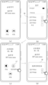
as shown in fig. 8 (a), the incoming call interface includes a put-out control, a device selection control 02, a reject control, and an answer control. When the user wants to make a multi-person call, the user can click on the device selection control 02, so that the mobile phone 2 invokes an interface, and a device list which has established a bluetooth connection with the mobile phone 2 is obtained from the bluetooth application, for example, the device list includes a bluetooth headset a, a bluetooth headset B and a watch. Then, the mobile phone 2 displays a selected audio device window 03 as shown in fig. 8 (B), and the audio device window 03 includes the identifications of the bluetooth headset a, the bluetooth headset B, and the wristwatch. If the user selects the bluetooth headset a and the bluetooth headset B from the select audio device window 03, the handset 2 immediately configures voice paths for the bluetooth headset a and the bluetooth headset B, respectively. After the mobile phone 2 configures voice paths for the bluetooth headset a and the bluetooth headset B, respectively, a user wearing the bluetooth headset a and a user wearing the bluetooth headset B can hear incoming call ringtones respectively. Then, as shown in fig. 8 (c), the user clicks the answer control 04, and the handset 2 establishes a call link with the handset 1. Thereafter, the mobile phone 2 displays a talking interface as shown in (d) of fig. 8. Thus, the Bluetooth headset A and the Bluetooth headset B can play the voice data from the mobile phone 1, and can also send the collected voice data to the mobile phone 1 through the mobile phone 2.
Another display mode of the incoming call interface is as follows:
as shown in fig. 9 (a), the incoming interface does not include a device selection control. When the user wants to make a multi-user call, as shown in (B) of fig. 9, the user may trigger the mobile phone 2 to display a shortcut window such as a toolbar or menu bar through a pull-down operation, and perform a selection operation on the device selection control 05 in the shortcut window, so that the mobile phone 2 invokes an interface, and obtains a device list that has established a bluetooth connection with the mobile phone 2 from a bluetooth application, where the device list includes a bluetooth headset a, a bluetooth headset B, and a watch. Then, the mobile phone 2 displays a selected audio device window 06 as shown in (c) of fig. 9, and the audio device window 06 includes the identifications of the bluetooth headset a, the bluetooth headset B, and the wristwatch. If the user selects the bluetooth headset a and the bluetooth headset B from the select audio device window 06, the handset 2 immediately configures voice paths for the bluetooth headset a and the bluetooth headset B, respectively. After the mobile phone 2 configures voice paths for the bluetooth headset a and the bluetooth headset B, respectively, a user wearing the bluetooth headset a and a user wearing the bluetooth headset B can hear incoming call ringtones respectively. Then, the user clicks the answer control, and the mobile phone 2 establishes a call link with the mobile phone 1. Thereafter, the mobile phone 2 displays a talking interface as shown in (d) of fig. 9. Thus, the bluetooth headset a and the bluetooth headset B can respectively play the voice data from the mobile phone 1, and also can send the collected voice data to the mobile phone 1 through the mobile phone 2.
It should be noted that, in fig. 8 and fig. 9, the user selects at least two audio devices in the audio device window, and then clicks the answer control to trigger the mobile phone 2 to establish a call link with the mobile phone 1. Fig. 10 provides an example of another alternative audio device.
For example, the user may also click on the answering control 07 shown in fig. 10 (a) first, trigger the handset 2 to establish a call link with the handset 1, click on the device selection control 08 shown in fig. 10 (B), or click on the device selection control 09 shown in fig. 10 (c), and then the handset 2 invokes an interface to obtain a list of devices that have established a bluetooth connection with the handset 2 from the bluetooth application, such as a list of devices including the bluetooth headset a, the bluetooth headset B, and the watch. Thereafter, the mobile phone 2 displays a selected audio device window 10 as shown in (d) of fig. 10, and the audio device window 10 includes the identifications of the bluetooth headset a, the bluetooth headset B, and the wristwatch. If the user selects the bluetooth headset a and the bluetooth headset B from the select audio device window 10, the handset 2 immediately configures voice paths for the bluetooth headset a and the bluetooth headset B, respectively. Thus, the Bluetooth headset A and the Bluetooth headset B can play the voice data from the mobile phone 1, and can also send the collected voice data to the mobile phone 1 through the mobile phone 2.
Second scene of
Under the condition that the Bluetooth connection between the mobile phone 2 and the audio equipment is not established in advance, if the mobile phone 2 receives a call service request from the mobile phone 1, a user can select the connected Bluetooth equipment in the Bluetooth interface, then the user returns to the call interface, and the list of the audio equipment can be refreshed automatically. In this way, the user can select at least two audio devices for use as audio input/output devices from the selection audio device window, and configure a voice path for each of the at least two audio devices, respectively.
Illustratively, assume that handset 2 has not previously established a bluetooth connection with an audio device. When the mobile phone 2 receives a call service request from the mobile phone 1, the mobile phone 2 displays an incoming call interface as shown in (a) of fig. 11. Since the handset 2 has not yet established a connection with the audio device, the incoming interface may not include a device selection control. When the user wants to make a multi-person call, the user can switch from the slave interface to the bluetooth interface 11 shown in fig. 11 (B), and the bluetooth interface 11 includes the identifiers of the searched available devices, such as the bluetooth headset a, the bluetooth headset B, the bluetooth headset C and the watch. Then, after the user selects the bluetooth headset a and the bluetooth headset B, the bluetooth headset a and the bluetooth headset B establish a bluetooth connection with the mobile phone 2. The user may return from bluetooth interface 11 as shown in fig. 11 (b) to an incoming call interface as shown in fig. 11 (c), which may include device selection control 12. The user may click on the device selection control 12 and the handset 2 displays a select audio device window 13 as shown in fig. 11 (d). If the user selects the bluetooth headset a and the bluetooth headset B from the audio device selection window 13, the handset 2 configures a voice path for the bluetooth headset a and the bluetooth headset B so that the user wearing the bluetooth headset a and the user wearing the bluetooth headset B can hear incoming ring tones, respectively. After that, the user clicks the answer control, and the mobile phone 2 establishes a call link with the mobile phone 1. Thus, the bluetooth headset a and the bluetooth headset B can respectively play the voice data from the mobile phone 1, and also can send the collected voice data to the mobile phone 1 through the mobile phone 2.
It should be noted that, in fig. 11, a user selects a plurality of audio devices on a bluetooth interface to trigger establishment of a bluetooth connection; then selecting audio equipment in the window for selecting audio equipment, and triggering configuration voice channels; then click on answer control, trigger mobile phone 2 and mobile phone 1 to establish the conversation link to illustrate. In other embodiments, the user may click the answer control first to trigger the mobile phone 2 to establish a call link with the mobile phone 1; then selecting a plurality of audio devices on the Bluetooth interface, and triggering to establish Bluetooth connection; the audio device is then selected in the select audio device window, triggering the configure voice path.
Third scenario
The first scenario described above exemplifies a scenario in which the user selects an audio device from a plurality of audio devices that have previously established a connection with the mobile phone 2 when the mobile phone 2 receives a call service request from the mobile phone 1. The third scenario differs from the first scenario in that: the third scenario is exemplified by the mobile phone 2 initiating a call service request to the mobile phone 1, and the user selects an audio device with a bluetooth connection established as a scenario of the audio device of the mobile phone 2.
Illustratively, assume that handset 2 has previously established a bluetooth connection with bluetooth headset a, bluetooth headset B, and a wristwatch. When the mobile phone 2 initiates a call service request to the mobile phone 1, the mobile phone 2 displays a call interface. As shown in fig. 12 (a), the de-powered interface includes a device selection control 14. Before the mobile phone 1 answers the call, if the user using the mobile phone 2 wants to make a multi-person call, the user using the mobile phone 2 can click on the device selection control 14, so that the mobile phone 2 invokes an interface to obtain a device list, such as a device list including a bluetooth headset a, a bluetooth headset B and a watch, from the bluetooth application, which has established a bluetooth connection with the mobile phone 2. Then, the cellular phone 2 displays a selected audio device window 15 as shown in (b) in fig. 12. The selected audio device interface 15 includes a bluetooth headset a, a bluetooth headset B, and an identification of the wristwatch. If the user selects the identifications of the bluetooth headset a and the bluetooth headset B from the selected audio device interface 15, the handset 2 configures voice paths for the bluetooth headset a and the bluetooth headset B, respectively. After the mobile phone 2 configures voice paths for the bluetooth headset a and the bluetooth headset B, respectively, a user wearing the bluetooth headset a and a user wearing the bluetooth headset B can hear the ring back tone from the mobile phone 1, respectively. If the user using handset 1 answers the call, handset 2 establishes a call link with handset 1. Then, the mobile phone 2 displays the in-call interface as shown in (c) in fig. 12. Thus, the bluetooth headset a and the bluetooth headset B can respectively play the voice data from the mobile phone 1, and also can send the collected voice data to the mobile phone 1 through the mobile phone 2.
It should be noted that, in fig. 12, a user selects a plurality of audio devices in an audio device window, and triggers the mobile phone 2 to configure a voice path for the plurality of audio devices; clicking the answer control to trigger the mobile phone 2 to establish a call link with the mobile phone 1 is taken as an example for illustration. It can be understood that when in actual implementation, the answer control can be clicked first to trigger the mobile phone 2 to establish a call link with the mobile phone 1; and selecting a plurality of audio devices in the audio device window, and triggering the mobile phone 2 to configure voice paths for the plurality of audio devices.
In addition, fig. 12 is an illustration of an example of setting a device selection control in a power-down interface, which is not limited to the embodiment of the present application. It can be understood that in actual implementation, the device selection control can also be set in a shortcut window such as a toolbar or a menu bar, and can be set according to actual use requirements.
Fourth scenario
The fourth scenario differs from the third scenario in that: the third scenario is illustrated by taking as an example that after the mobile phone 2 initiates a call service request to the mobile phone 1, the user selects an audio device from a plurality of audio devices that are pre-connected to the mobile phone 2. The fourth scenario is illustrated by taking how to connect and select an audio device if the mobile phone 2 is not connected to any audio device in advance after the mobile phone 2 initiates a call service request to the mobile phone 1.
Illustratively, assume that handset 2 has not previously established a bluetooth connection with an audio device. When the mobile phone 2 initiates a call service request to the mobile phone 1, the mobile phone 2 displays a call-out interface as shown in (a) of fig. 13, where the call-out interface does not include a device selection control. After the user using the handset 1 answers the call, the handset or microphone of the handset 2 may play the voice data from the handset 1. If the user using the handset 2 wants to make a multi-person call, the user can switch from the on-call interface to the bluetooth interface 16 shown in fig. 13 (B), the bluetooth interface 16 including the identification of available devices searched by the handset 2, such as the identifications of bluetooth headset a, bluetooth headset B, bluetooth headset C and the wristwatch. After the user selects the bluetooth headset a and the bluetooth headset B, the bluetooth headset a and the bluetooth headset B establish a bluetooth connection with the mobile phone 2. The user may return from the bluetooth interface shown in fig. 13 (b) to the talking interface shown in fig. 13 (c), and the list of audio devices may be automatically refreshed. The user may click on the device selection control 17 and the handset 2 displays a select audio device window 18 as shown in fig. 13 (d). Wherein the select audio device window 18 includes identifications of bluetooth headset a and bluetooth headset B for which a bluetooth connection has been established. If the user selects the bluetooth headset a and bluetooth headset B from the select audio device window 18, the handset 2 configures a voice path for the bluetooth headset a and bluetooth headset B. Thus, the bluetooth headset a and the bluetooth headset B can respectively play the voice data from the mobile phone 1, and also can send the collected voice data to the mobile phone 1 through the mobile phone 2.
It should be noted that, during the call, the user can also replace the audio device connected with the mobile phone at any time. In one way, if the previous selected audio device window includes an audio device that the user wants to replace, the user can trigger the handset 2 to display the selected audio device window directly through input to the device selection control, and then reselect the audio device in the selected audio device window, so that the handset 2 configures a voice path for the reselected audio device. Alternatively, if the previous selected audio device window does not include an audio device that the user wants to replace, the user may first reselect a connected audio device in the bluetooth interface and then select a configured audio device in the selected audio device window, so that the handset 2 configures a voice path for the reselected audio device. It should be noted that, for the specific implementation manners of the two manners, reference may be made to the description of the foregoing embodiments for related situations, which is not repeated herein.
The above embodiments are described by taking a telephone call service as an example, and are not limited to the embodiments of the present application. When the mobile phone 2 receives a request for a video call service or an audio call service from the mobile phone 1, or when the mobile phone 2 initiates a request for a video call service or an audio call service to the mobile phone 1, a scheme similar to the call service may be adopted to configure a voice path for a plurality of audio devices selected by a plurality of users using the mobile phone 2, which will not be described herein.
Fig. 14 is a flowchart of a call method using a plurality of audio devices according to an embodiment of the present application. The method can be applied to a scene of realizing multi-person conversation by adopting a plurality of audio devices connected with the electronic device, for example, a scene of receiving conversation services as shown in fig. 8 to 11. The execution subject of the method may be an electronic device or a functional module in an electronic device connected to a plurality of audio devices. The method will be described below taking the execution subject as the mobile phone 2 as an example.
As shown in fig. 14, the method may include S201 to S209 described below.
S201, the mobile phone 2 receives a call service request from the mobile phone 1.
The call service request may be a phone call request, a video call request, or an audio call request, which is not limited in this embodiment.
S202, when the mobile phone 2 and the mobile phone 1 do not establish a call link, the mobile phone 2 displays an incoming call interface.
For example, in a case where the handset 2 and the handset 1 have not established a call link, the handset 2 may display an incoming call interface as shown in (a) in fig. 8, as shown in (a) in fig. 9, as shown in (a) in fig. 10, or as shown in (a) in fig. 11. The incoming interface may include an answer control, a reject control, and the like. The handset 2 continuously detects whether a user operation of these controls has been received. If the mobile phone 2 receives a selection operation of the device selection control by the user, S203, S204, and S207 described below are performed. If the mobile phone 2 receives a selection operation of the interface control by the user, the following S205 to S206 are performed. If the handset 2 receives a user selection operation of the reject control, the step is ended.
S203, the mobile phone 2 displays a device identification list.
S204, the mobile phone 2 responds to the selection input of a plurality of identifiers in the device identifier list by a user, and a voice channel is respectively configured for each of a plurality of audio devices indicated by the plurality of identifiers.
S205, the mobile phone 2 establishes a call link with the mobile phone 1, and displays a call interface.
S206, when the mobile phone 2 receives the selection operation of the user on the equipment selection control, the mobile phone 2 displays an equipment identification list. After the mobile phone 2 displays the device identification list, the mobile phone 2 receives a user selection input of a plurality of audio device identifications in the device identification list. The handset 2 configures a voice path for each of the plurality of audio devices in response to the selection input.
For a specific implementation manner of displaying the device identifier list on the mobile phone 2 and selecting a plurality of audio devices by the user, reference may be made to the description in the foregoing embodiments, which is not repeated herein.
S207, when the mobile phone 2 receives the selection operation of the user on the device selection control, the mobile phone 2 establishes a call link with the mobile phone 1, and the mobile phone 2 displays a call interface.
S208, the mobile phone 2 receives the far-end voice data from the mobile phone 1 through the call link, and receives a plurality of voice data from a plurality of audio devices through a plurality of voice paths.
It should be noted that, the far-end voice data from the mobile phone 1 may be referred to as first voice data, and the voice data from the audio device may be referred to as second voice data.
S209, the mobile phone 2 sends the first mixed data to the mobile phone 1 through a call link, and sends the second mixed data to the target audio device through a target voice channel in a plurality of voice channels.
The first audio mixing data is audio data obtained by mixing a plurality of audio data.
The target audio device is any one of a plurality of audio devices. The second mixing data is voice data obtained by mixing the remote voice data and voice data except the target voice data in the voice data. The target voice data is voice data from a target audio device.
Fig. 15 is a flowchart of another call method using a plurality of audio devices according to an embodiment of the present application. The method can be applied to a scene of realizing multi-person conversation by adopting a plurality of audio devices connected with the electronic device, for example, the scene of initiating conversation service shown in fig. 12 to 13. The execution subject of the method may be an electronic device or a functional module in an electronic device connected to a plurality of audio devices. The method will be described below taking the execution subject as the mobile phone 2 as an example.
As shown in fig. 15, the method may include S301-S311 described below.
S301, the mobile phone 2 sends a call service request to the mobile phone 1.
The call service request may be a telephone call request, a video call request, or an audio call request.
S302, when the mobile phone 2 and the mobile phone 1 do not establish a call link, the mobile phone 2 displays a power-off interface.
S303, the mobile phone 2 detects whether an operation of the device selection control is received.
If the mobile phone 2 receives a selection operation of the device selection control by the user, the following S304-S306 are performed.
If the mobile phone 2 does not receive the user selection operation of the device selection control, S307 to S309 described below are performed.
S304, the mobile phone 2 displays a device identification list.
S305, the mobile phone 2 responds to the selection input of a plurality of identifiers in the device identifier list by a user, and respectively configures a voice channel for each of a plurality of audio devices indicated by the plurality of identifiers.
The handset 2 then establishes a plurality of voice paths with a plurality of audio devices, one for each voice path.
S306, the mobile phone 2 responds to the selection operation of the user to the interface control, establishes a call link with the mobile phone 1, and displays a call interface.
S307, the mobile phone 2 establishes a call link with the mobile phone 1 and displays a call interface.
And S308, when the mobile phone 2 receives the selection operation of the user on the equipment selection control, the mobile phone 2 displays an equipment identification list.
S309, the mobile phone 2 receives user selection input of a plurality of audio equipment identifiers in the equipment identifier list. The handset 2 configures a voice path for each of the plurality of audio devices in response to the selection input.
The handset 2 then establishes a plurality of voice paths with a plurality of audio devices, one for each voice path.
For a specific implementation manner of displaying the device identifier list on the mobile phone 2 and selecting a plurality of audio devices by the user, reference may be made to the description in the foregoing embodiments, which is not repeated herein.
S310, the mobile phone 2 receives the far-end voice data from the mobile phone 1 through a call link and receives a plurality of voice data from a plurality of audio devices through a plurality of voice paths.
S311, the mobile phone 2 sends the first mixed data to the mobile phone 1 through a call link, and sends the second mixed data to the target audio device through a target voice channel in a plurality of voice channels.
The first audio mixing data is audio data obtained by mixing a plurality of audio data.
The target audio device is any one of a plurality of audio devices. The second mixing data is voice data obtained by mixing the remote voice data and voice data except the target voice data in the voice data. The target voice data is voice data from a target audio device.
In order to more clearly understand the mixing scheme introduced in fig. 14 and 15, the following description will be given by way of three examples, taking the bluetooth headset a and the bluetooth headset B as audio input/output devices of the mobile phone 2 as examples.
Example 1
Fig. 16 shows a schematic diagram of a mixing scenario provided in an embodiment of the present application. Accordingly, fig. 17 shows an architecture diagram corresponding to the mobile phone 2 of fig. 16.
As shown in fig. 16, the handset 2 establishes a call link with the handset 1, the handset 2 establishes a voice path a with the bluetooth headset a, and the handset 2 establishes a voice path B with the bluetooth headset B. After the microphone of the bluetooth headset a collects the voice of the user 2, the voice of the user 2 is converted into voice data a, and the voice data a is sent to the mobile phone 2 through the voice channel a. After the microphone of the bluetooth headset B collects the voice of the user 3, the voice of the user 3 is converted into voice data B, and the voice data a is sent to the mobile phone 2 through the voice channel B. If the mobile phone 2 receives the voice channel a and the voice data b at the same time, the voice channel a and the voice data b are mixed to obtain mixed data, and the mixed data is sent to the mobile phone 1 through a communication link. The mobile phone 1 receives the mix data and plays sound according to the mix data, so that the user 1 using the mobile phone 1 can hear the sound of the user 2 and the user 3.
As shown in fig. 17, the mobile phone 2 includes: the system comprises a call application of an application layer, an audio management (AudioManager) module of a framework layer, an audio policy (AudioPolicy) module of a library layer, bluetooth Hal of a hardware abstraction layer, PCM virtual equipment of a kernel layer, and a modem, an ADSP and a Bluetooth chip of a hardware layer.
When the user operates the mobile phone 2 to answer a call, dial a call, answer a video call, initiate a video call, answer a voice call or initiate a voice call, the call application starts call audio in response to the user operation, and sends a configuration instruction to an audio policy (AudioPolicy) module through an API provided by an audio management (AudioManager) module. The configuration instruction is used for indicating the configuration of voice paths for the Bluetooth headset A and the Bluetooth headset B. An audio policy (AudioPolicy) module turns on PCM virtual devices for serving two bluetooth headsets through bluetooth Hal in response to a configuration instruction. Then, the PCM virtual device configures a voice path a for the bluetooth headset a and configures a voice path B for the bluetooth headset B. The Bluetooth headset A, the Bluetooth chip and the ADSP are connected through a voice channel a, and the Bluetooth headset B, the Bluetooth chip and the ADSP are connected through a voice channel B. Thus, the voice data a is firstly sent to the Bluetooth chip through the voice channel a between the Bluetooth headset A and the Bluetooth chip, and then is sent to the ADSP through the voice channel a between the Bluetooth chip and the ADSP. The voice data B is firstly sent to the Bluetooth chip through a voice channel B between the Bluetooth headset B and the Bluetooth chip, and then is sent to the ADSP through the voice channel B between the Bluetooth chip and the ADSP. When the ADSP receives the voice channel a and the voice data b at the same time, the ADSP mixes the voice channel a and the voice data b to obtain mixed data, and sends the mixed data to the modem. The modem modulates the mixed data from a digital signal to a medium-high frequency signal and transmits the mixed data through an antenna.
Example 2
Fig. 18 shows a schematic diagram of another mixing scenario provided in an embodiment of the present application. Accordingly, fig. 19 shows an architecture diagram corresponding to the mobile phone 2 of fig. 18.
As shown in fig. 18, the handset 2 establishes a call link with the handset 1, the handset 2 establishes a voice path a with the bluetooth headset a, and the handset 2 establishes a voice path B with the bluetooth headset B. After the microphone of the mobile phone 1 collects the voice of the user 1, the voice of the user 1 is converted into remote voice data, and the remote voice data is sent to the mobile phone 2 through a communication link. After the microphone of the bluetooth headset a collects the voice of the user 2, the voice of the user 2 is converted into voice data a, and the voice data a is sent to the mobile phone 2 through the voice channel a. If the mobile phone 2 receives the far-end voice data and the voice data a at the same time, the far-end voice data and the voice data a are mixed to obtain mixed data, and the mixed data is sent to the Bluetooth headset B through the voice channel B. The bluetooth headset B receives the mix data and plays sound according to the mix data, so that the user 3 using the bluetooth headset B can hear the sound of the user 1 and the user 2.
As shown in fig. 19, the mobile phone 2 includes: the system comprises a call application of an application layer, an audio management (AudioManager) module of a framework layer, an audio policy (AudioPolicy) module of a library layer, bluetooth Hal of a hardware abstraction layer, PCM virtual equipment of a kernel layer, and a modem, an ADSP and a Bluetooth chip of a hardware layer.
When the user operates the mobile phone 2 to answer a call, dial a call, answer a video call, initiate a video call, answer a voice call or initiate a voice call, the call application starts call audio in response to the user operation, and sends a configuration instruction to an audio policy (AudioPolicy) module through an API provided by an audio management (AudioManager) module. The configuration instruction is used for indicating the configuration of voice paths for the Bluetooth headset A and the Bluetooth headset B. An audio policy (AudioPolicy) module turns on PCM virtual devices for serving two bluetooth headsets through bluetooth Hal in response to a configuration instruction. Then, the PCM virtual device configures a voice path a for the bluetooth headset a and configures a voice path B for the bluetooth headset B. The Bluetooth headset A, the Bluetooth chip and the ADSP are connected through a voice channel a, and the Bluetooth headset B, the Bluetooth chip and the ADSP are connected through a voice channel B. In this way, the modem demodulates the far-end voice data from the call peripheral (such as the mobile phone 1), and sends the demodulated far-end voice data to the ADSP through the call link. In addition, the voice data a is firstly sent to the Bluetooth chip through a voice channel a between the Bluetooth headset A and the Bluetooth chip, and then is sent to the ADSP through the voice channel a between the Bluetooth chip and the ADSP. When the ADSP receives the far-end voice data and the voice data a at the same time, the ADSP mixes the far-end voice data and the voice data a to obtain mixed voice data, and the mixed voice data is sent to the Bluetooth chip through a voice channel b between the ADSP and the Bluetooth chip. Then, the bluetooth chip transmits the mixing data to the bluetooth headset B through the voice path B with the bluetooth headset B.
Example 3
Fig. 20 shows a schematic diagram of still another mixing scenario provided in an embodiment of the present application. Accordingly, fig. 21 shows an architecture diagram corresponding to the mobile phone 2 of fig. 20.
As shown in fig. 20, the handset 2 establishes a call link with the handset 1, the handset 2 establishes a voice path a with the bluetooth headset a, and the handset 2 establishes a voice path B with the bluetooth headset B. After the microphone of the mobile phone 1 collects the voice of the user 1, the voice of the user 1 is converted into remote voice data, and the remote voice data is sent to the mobile phone 2 through a communication link. After the microphone of the bluetooth headset B collects the voice of the user 3, the voice of the user 3 is converted into voice data B, and the voice data B is sent to the mobile phone 2 through the voice channel B. If the mobile phone 2 receives the far-end voice data and the voice data b at the same time, the far-end voice data and the voice data b are mixed to obtain mixed data, and the mixed data is sent to the Bluetooth headset A through the voice channel a. The bluetooth headset a receives the mix data and plays sound according to the mix data, so that the user 2 using the bluetooth headset a can hear the sound of the user 1 and the user 3.
As shown in fig. 21, the mobile phone 2 includes: the system comprises a call application of an application layer, an audio management (AudioManager) module of a framework layer, an audio policy (AudioPolicy) module of a library layer, bluetooth Hal of a hardware abstraction layer, PCM virtual equipment of a kernel layer, and a modem, an ADSP and a Bluetooth chip of a hardware layer.
When the user operates the mobile phone 2 to answer a call, dial a call, answer a video call, initiate a video call, answer a voice call or initiate a voice call, the call application starts call audio in response to the user operation, and sends a configuration instruction to an audio policy (AudioPolicy) module through an API provided by an audio management (AudioManager) module. The configuration instruction is used for indicating the configuration of voice paths for the Bluetooth headset A and the Bluetooth headset B. An audio policy (AudioPolicy) module turns on PCM virtual devices for serving two bluetooth headsets through bluetooth Hal in response to a configuration instruction. Then, the PCM virtual device configures a voice path a for the bluetooth headset a and configures a voice path B for the bluetooth headset B. The Bluetooth headset A, the Bluetooth chip and the ADSP are connected through a voice channel a, and the Bluetooth headset B, the Bluetooth chip and the ADSP are connected through a voice channel B. In this way, the modem demodulates the far-end voice data from the call peripheral (such as the mobile phone 1), and sends the demodulated far-end voice data to the ADSP through the call link. In addition, the voice data B is firstly sent to the Bluetooth chip through a voice channel B between the Bluetooth headset B and the Bluetooth chip, and then is sent to the ADSP through the voice channel B between the Bluetooth chip and the ADSP. When the ADSP receives the far-end voice data and the voice data b at the same time, the ADSP mixes the far-end voice data and the voice data b to obtain mixed voice data, and the mixed voice data is sent to the Bluetooth chip through a voice channel a between the ADSP and the Bluetooth chip. Then, the bluetooth chip transmits the mixing data to the bluetooth headset a through the voice path a with the bluetooth headset a.
ADSP is described in example 1, example 2, and example 3 above. In order to more clearly illustrate the ADSP, the hardware structure and the operation principle of the ADSP will be described in detail with reference to fig. 22.
In fig. 22, the handset includes ADSP, bluetooth Hal, PCM virtual device, modem, audio codec, and bluetooth chip. Wherein the ADSP is used for performing audio mixing processing on audio data from each device. Bluetooth Hal and PCM virtual devices are used to configure a dual bluetooth headset path. The modem is used to modulate and demodulate audio data. The audio codec includes a serial-chip-to-chip media bus (SLIMBUS) module with low power consumption for connecting a baseband/application processor (e.g., ADSP) and a communication chip (e.g., bluetooth chip), and the SLIMBUS module ensures that both control information and data information can be transmitted. The Bluetooth chip is used for transmitting audio data and control instructions.
In some embodiments, the ADSP includes a codec module, an audio effect module, a mixer, a bluetooth sound pickup module 1, and a bluetooth sound pickup module 2. The codec is used to encode and decode voice data. The Bluetooth pickup module 1 is used for acquiring voice data from the Bluetooth headset A. The bluetooth pickup module 2 is used for obtaining voice data from the bluetooth headset B. The sound effect module is used for performing sound effect processing, such as volume adjustment, sound beautification, volume quantization and the like, on each voice data. The mixer is used for integrating a plurality of voice data into one stereo track or single track, i.e. mixing the voice data.
Specifically, fig. 22 shows 6 passages. By adopting the channel (1), the uplink voice data a collected by the Bluetooth headset A can be sequentially transmitted to the mixer through the Bluetooth chip, the audio codec, the Bluetooth pickup module 1 and the sound effect module. By adopting the channel (2), the uplink voice data B collected by the Bluetooth headset B can be sequentially transmitted to the mixer through the Bluetooth chip, the audio codec, the Bluetooth pickup module 2 and the sound effect module. By adopting the channel (3), the remote voice data received by the modem can be sequentially transmitted to the mixer through the encoding and decoding module and the sound effect module. By adopting the channel (4), the mixed data of the uplink voice data a and the uplink voice data b can be transmitted to the call peripheral equipment through the encoding and decoding module and the modem in sequence. By adopting the channel (5), the mixed sound data of the far-end voice data and the uplink voice data b can be sequentially transmitted to the Bluetooth headset A through the audio codec and the Bluetooth chip. By adopting the channel (6), the mixed sound data of the far-end voice data and the uplink voice data a can be sequentially transmitted to the Bluetooth headset B through the audio codec and the Bluetooth chip.
The PCM virtual device will be described in detail below.
In the Linux system, all devices are finally abstracted into one or more device files which can be accessed by a user space, and the process of the user space achieves the purpose of controlling hardware through reading and writing of the device files. PCM virtual devices belong to device files and are therefore also referred to as PCM device files. The workflow of the PCM virtual device includes: creating (create) a PCM device file, opening (open) the PCM device file, writing (write)/reading (read) the PCM device file, and closing the PCM device file. In general, the kernel layer may create one or more PCM device files. Each PCM device file is used to provide services for one or more audio devices. Since different PCM device files are used to serve different audio devices. Therefore, during the call, the user can select the audio device according to the actual use requirement, so that the electronic device can create and open the PCM device file corresponding to the audio device selected by the user.
When one electronic device receives a call service request from other devices, or when the one electronic device initiates the call service request to the other electronic devices, the audio Hal or Bluetooth Hal of the one electronic device realizes multi-user call by reading and writing the PCM device file. One scenario is that when an audio policy (AudioPolicy) module receives a configuration instruction for configuring a voice path for a plurality of audio devices, if a plurality of PCM device files have been created, one PCM device file corresponding to the plurality of audio devices is determined directly from the plurality of PCM device files according to the configuration instruction, and the one PCM device file is opened. Another scenario is that when an audio policy (AudioPolicy) module receives a configuration instruction for configuring a voice path for a plurality of audio devices, if PCM device files corresponding to the plurality of audio devices have not been created yet, one PCM device file corresponding to the plurality of audio devices is created, and the one PCM device file is opened. After opening the PCM device file, the electronic device may read the PCM device file, configuring a voice path for the plurality of audio devices. After the call service is finished, the electronic device closes the PCM device file.
The above embodiments are described by taking the example of the electronic device and the audio device connected through bluetooth. In the embodiment of the application, the mobile phone and the audio device can be connected through a wire. Taking a wired earphone as an example, when the electronic device detects that the wired earphone is plugged in, a voice channel is configured for the wired earphone.
As an example, fig. 23 shows an architecture diagram of a voice path configured by a PCM virtual device. As shown in fig. 23, after the call application starts call audio in response to a user operation, a configuration instruction is transmitted to an audio policy (AudioPolicy) module through an API provided by an audio management (AudioManager) module. The configuration instruction is used for indicating the configuration of the voice path for the wired earphone and the Bluetooth earphone. An audio policy (AudioPolicy) module turns on PCM virtual devices for serving wired headphones and bluetooth headphones through audio Hal in response to a configuration instruction. Then, the PCM virtual device configures a voice path a for the wired headset and configures a voice path b for the bluetooth headset. The Bluetooth headset, the Bluetooth chip and the ADSP establish connection through the voice channel b. The wired earphone and ADSP establish a connection through voice path a. In this way, the modem demodulates the far-end voice data from the call peripheral, and sends the demodulated far-end voice data to the ADSP through the call link. Voice data collected by the wired earphone is transmitted to the ADSP through the voice channel a. The voice data collected by the Bluetooth headset is transmitted to the ADSP through the voice channel b. Then, the ADSP mixes the individual voice data. The implementation manner of mixing each voice data by the ADSP may refer to the description of the foregoing embodiments, which is not repeated herein.
As an example, fig. 24 shows another architecture diagram of a voice path configured by a PCM virtual device. As shown in fig. 24, after the call application starts call audio in response to a user operation, a configuration instruction is transmitted to an audio policy (AudioPolicy) module through an API provided by an audio management (AudioManager) module. The configuration instruction is used for indicating to configure a voice path for the Bluetooth headset and the Bluetooth watch. An audio policy (AudioPolicy) module turns on PCM virtual devices for serving bluetooth headsets and bluetooth watches through bluetooth Hal in response to configuration instructions. Then, the PCM virtual device configures a voice path a for the bluetooth headset and a voice path b for the bluetooth wristwatch. The Bluetooth headset, the Bluetooth chip and the ADSP are connected through a voice channel a, and the Bluetooth watch, the Bluetooth chip and the ADSP are connected through a voice channel b. In this way, the modem demodulates the far-end voice data from the call peripheral, and sends the demodulated far-end voice data to the ADSP through the call link. The voice data collected by the Bluetooth headset is transmitted to the ADSP through the voice channel a. The voice data collected by the Bluetooth watch is transmitted to the ADSP through the voice channel b. Then, the ADSP mixes the individual voice data. The implementation manner of mixing each voice data by the ADSP may refer to the description of the foregoing embodiments, which is not repeated herein.
The above description has been made mainly from the point of view of the electronic device. It will be appreciated that the electronic device, in order to achieve the above-described functions, may comprise a corresponding hardware structure or software module, or a combination thereof, for performing each function. Those of skill in the art will readily appreciate that the elements and algorithm steps of the examples described in connection with the embodiments disclosed herein may be implemented as hardware or combinations of hardware and computer software. Whether a function is implemented as hardware or computer software driven hardware depends upon the particular application and design constraints imposed on the solution. Skilled artisans may implement the described functionality in varying ways for each particular application, but such implementation decisions should not be interpreted as causing a departure from the scope of the present application.
The embodiment of the application may divide the functional modules of the electronic device according to the above method example, for example, each functional module may be divided corresponding to each function, or two or more functions may be integrated into one processing module. The integrated modules may be implemented in hardware or in software functional modules. It should be noted that, in the embodiment of the present application, the division of the modules is schematic, which is merely a logic function division, and other division manners may be implemented in actual implementation. The following description will take an example of dividing each function module into corresponding functions.
Fig. 25 is a schematic structural diagram of a call device according to an embodiment of the present application. The call apparatus may correspond to performing the methods described in the embodiments of the present application. As shown in fig. 25, the telephony device may include a control module 501 and a communication module 502.
The control module 501 is configured to establish a plurality of voice paths with a plurality of audio devices, where one audio device corresponds to one voice path, in a case where a call link is established with the second device.
The communication module 502 is configured to receive far-end voice data from the second device through a call link, and receive a plurality of voice data from a plurality of audio devices through a plurality of voice paths.
The communication module 502 is further configured to send the first mix data to the second device through the call link, and send the second mix data to the target audio device through the target voice path of the plurality of voice paths.
The first audio mixing data is audio data obtained by mixing a plurality of audio data. The target audio device is any one of a plurality of audio devices. The second mixing data is voice data obtained by mixing the remote voice data and voice data except the target voice data in the voice data. The target voice data is voice data from a target audio device.
In some embodiments, the control module 501 is further configured to, before establishing a plurality of voice paths with the plurality of audio devices, configure a voice path for each of the plurality of audio devices separately in response to a user selection operation of the plurality of audio devices.
In some embodiments, the control module 501 is further configured to mix a plurality of voice data to obtain first mixed data; and mixing the remote voice data and voice data except the target voice data in the voice data to obtain second mixed voice data.
The embodiment of the application also provides an electronic device, which comprises a processor, wherein the processor is coupled with the memory, and the processor is used for executing the computer program or the instructions stored in the memory, so that the electronic device realizes the method in each embodiment.
Embodiments of the present application also provide a computer-readable storage medium having a computer program stored therein. The computer readable storage medium, when run on an electronic device, causes the electronic device to perform the method as shown above. The computer instructions may be stored in a computer-readable storage medium or transmitted from one computer-readable storage medium to another computer-readable storage medium, for example, the computer instructions may be transmitted from one website, computer, server, or data center to another website, computer, server, or data center by a wired (e.g., coaxial cable, fiber optic, digital subscriber line (digital subscriber line, DSL)) or wireless (e.g., infrared, wireless, microwave, etc.). The computer readable storage medium can be any available medium that can be accessed by a computer or a data storage device including one or more servers, data centers, etc. that can be integrated with the medium. The usable medium may be a magnetic medium (e.g., a floppy disk, a hard disk, or a magnetic tape), an optical medium, or a semiconductor medium (e.g., a Solid State Disk (SSD)), or the like.
The present application also provides a computer program product comprising computer program code for causing a computer to perform the method of the embodiments described above when the computer program code is run on the computer.
Embodiments of the present application also provide a chip coupled to a memory, the chip being configured to read and execute a computer program or instructions stored in the memory to perform the methods of the embodiments described above. The chip may be a general-purpose processor or a special-purpose processor.
It should be noted that the chip may be implemented using the following circuits or devices: one or more field programmable gate arrays (field programmable gate array, FPGA), programmable logic devices (programmable logic device, PLD), controllers, state machines, gate logic, discrete hardware components, any other suitable circuit or combination of circuits capable of performing the various functions described throughout this application.
The electronic device, the call device, the computer readable storage medium, the computer program product and the chip provided in the embodiments of the present application are all configured to execute the method provided above, so that the beneficial effects achieved by the method provided above can be referred to the beneficial effects corresponding to the method provided above, and are not repeated herein.
It should be understood that the foregoing is only intended to assist those skilled in the art in better understanding the embodiments of the present application and is not intended to limit the scope of the embodiments of the present application. It will be apparent to those skilled in the art from the foregoing examples that various equivalent modifications or variations can be made, for example, certain steps may not be necessary in the various embodiments of the detection methods described above, or certain steps may be newly added, etc. Or a combination of any two or more of the above. Such modifications, variations, or combinations are also within the scope of embodiments of the present application.
It should also be understood that the foregoing description of embodiments of the present application focuses on highlighting differences between the various embodiments and that the same or similar elements not mentioned may be referred to each other and are not described in detail herein for brevity.
It should be further understood that the sequence numbers of the above processes do not mean the order of execution, and the order of execution of the processes should be determined by the functions and the internal logic, and should not constitute any limitation on the implementation process of the embodiments of the present application.
It should be further understood that, in the embodiments of the present application, the "preset" and "predefined" may be implemented by pre-storing corresponding codes, tables, or other manners that may be used to indicate relevant information in a device (including, for example, an electronic device), and the present application is not limited to a specific implementation manner thereof.
It should also be understood that the manner, condition, class and division of the embodiments in the embodiments of the present application are for convenience of description only and should not be construed as being particularly limited, and the various manners, classes, conditions and features of the embodiments may be combined without contradiction.
It is also to be understood that in the various embodiments of the application, terms and/or descriptions of the various embodiments are consistent and may be referenced to one another in the absence of a particular explanation or logic conflict, and that the features of the various embodiments may be combined to form new embodiments in accordance with their inherent logic relationships.
Finally, it should be noted that: the foregoing description is merely specific embodiments of the present application, but the scope of the present application is not limited thereto, and any changes or substitutions within the technical scope of the present disclosure should be covered in the scope of the present application. Therefore, the protection scope of the present application shall be subject to the protection scope of the claims.
Claims (12)
1. A call method using a plurality of audio devices, applied to a first device, the first device including a modem, a communication chip, an audio digital signal processor ADSP and an audio codec, the ADSP including a codec module, a pickup module, an audio effect module and a mixer, the method comprising:
After a call service request is initiated to or received from a second device, the first device opens Pulse Code Modulation (PCM) virtual devices for providing services for the plurality of audio devices in response to a user selection operation on the plurality of audio devices, and configures a voice channel for each of the plurality of audio devices through the PCM virtual devices, wherein different PCM virtual devices are used for providing services for different audio devices;
the first equipment establishes a call link with the second equipment and establishes a plurality of voice channels with the plurality of audio equipment at the same time;
the first device receives first voice data from the second device through the modem based on the call link; and simultaneously receiving, by the communication chip, a plurality of second voice data from the plurality of audio devices based on the voice path established for each audio device;
the first device sends the first voice data subjected to decoding and sound effect processing to the sound mixer through the modem, the encoding and decoding module and the sound effect module in sequence based on the call link; and based on the voice channel established for each audio device, sequentially transmitting the second voice data subjected to decoding and sound effect processing to the mixer through the communication chip, the audio codec, the pickup module corresponding to each audio device and the sound effect module;
The first device mixes the plurality of second voice data through the mixer to obtain first mixed data; mixing the first voice data and voice data except target voice data in the plurality of second voice data through the mixer to obtain second mixed voice data, wherein the target voice data is voice data from target audio equipment, and the target audio equipment is any one of the plurality of audio equipment;
the first device sends the encoded first mixed data to the second device sequentially through the mixer, the encoding and decoding module and the modem based on the call link; and for each of the plurality of audio devices, the first device performs the following operations: and based on a voice channel established for the target audio equipment, sequentially transmitting the encoded second mixed data to the target audio equipment through the mixer, the audio codec and the communication chip.
2. The method of claim 1, wherein the selection operation is a triggering operation of a user's identification of the plurality of audio devices;
Before receiving the trigger operation of the user for the identification of the plurality of audio devices, the method further comprises:
after initiating a call service request to the second device or receiving the call service request from the second device, the first device judges whether to establish connection with an audio device;
if the first device establishes communication connection with the M audio devices, the first device displays a device selection control on a call interface or an incoming call interface;
the first device responds to the operation of the user on the device selection control, and the identifications of the M audio devices are displayed;
wherein the identification of the M audio devices includes identifications of the plurality of audio devices.
3. The method of claim 2, wherein the communication connection comprises a wireless connection; alternatively, the communication connection includes a wired connection and a wireless connection.
4. The method of claim 1, wherein the first device comprises a target application, an audio management module, and an audio policy module;
the first device, in response to a user selection operation on the plurality of audio devices, opens a PCM virtual device that serves the plurality of audio devices, and configures a voice path for each of the plurality of audio devices through the PCM virtual device, respectively, including:
The first device receives the selection operation through the target application program;
in response to the selection operation, the first device sends a configuration instruction to the audio policy module through an application programming interface provided by the audio management module, wherein the configuration instruction is used for indicating to configure voice paths for the plurality of audio devices;
the first device responds to the configuration instruction through the audio strategy module and opens the PCM virtual device for providing services for the plurality of audio devices;
the first device configures a voice path for each of the plurality of audio devices through the PCM virtual device, respectively.
5. The method of claim 4, wherein the first device, in response to the configuration instruction by the audio policy module, opening the PCM virtual device serving the plurality of audio devices, comprising:
the first device responding to the configuration instruction through the audio strategy module, creating the PCM virtual device for providing service for the plurality of audio devices, and opening the PCM virtual device; or, among the plurality of PCM virtual devices created by the first device, determining a PCM virtual device serving the plurality of audio devices, and turning on the PCM virtual device serving the plurality of audio devices.
6. The method of claim 4, wherein the first device further comprises a hardware abstraction layer module that is a communication interface between the audio policy module and the PCM virtual device;
the first device, in response to the configuration instruction through the audio policy module, opens the PCM virtual device serving the plurality of audio devices, comprising:
the first device responds to the configuration instruction through the audio strategy module and opens the PCM virtual device for providing service for the plurality of audio devices through the hardware abstraction layer module.
7. The method according to any one of claims 1 to 6, wherein the first device sequentially transmits the decoded and sound-processed first voice data to the mixer through the modem, the codec module, and the sound effect module based on the call link, comprising:
the first device sequentially performs the following operations based on the call link:
transmitting the first voice data received by the modem to the encoding and decoding module;
decoding the first voice data through the encoding and decoding module;
Performing sound effect processing on the decoded first voice data through the sound effect module;
and sending the first voice data after the sound effect processing to the mixer.
8. The method according to any one of claims 1 to 6, wherein transmitting the decoded and processed second voice data to the mixer through the communication chip, the audio codec, the pickup module corresponding to each audio device, and the sound effect module in order, respectively, based on a voice path established for each audio device, comprises:
the first device sequentially performs the following operations based on the voice channel established for each audio device:
the second voice data from each audio device received by the communication chip is respectively sent to the audio codec;
decoding, by the audio codec, second speech data from each audio device;
transmitting the decoded second voice data from each audio device to the sound effect module through the pickup module corresponding to each audio device;
performing sound effect processing on the decoded second voice data from each audio device through the sound effect module;
And sending the second voice data from each audio device after the sound effect processing to the mixer.
9. The method according to any one of claims 1 to 6, wherein the first device transmits the encoded first mix data to the second device sequentially through the mixer, the codec module, and the modem based on the talk link, comprising:
the first device sequentially performs the following operations based on the call link:
transmitting the first mixing data obtained by the mixer to the encoding and decoding module;
encoding the first mix data by the codec module;
transmitting the encoded first mix data to the modem;
and sending the encoded first mixed data to the second equipment through the modem.
10. The method according to any one of claims 1 to 6, wherein transmitting the encoded second mix data to the target audio device sequentially through the mixer, the audio codec, the communication chip based on the voice path established for the target audio device, comprises:
The first device sequentially performs the following operations based on a voice channel established for the target audio device:
transmitting the second mixing data obtained by the mixer to the audio codec;
encoding the second mix data by the audio codec;
and sending the encoded second audio mixing data to the second equipment through the communication chip.
11. An electronic device comprising a processor, and a memory and a communication interface coupled to the processor; wherein the memory is for storing computer instructions; the communication interface is used for interacting voice data with the audio equipment; the processor is configured to execute the computer instructions to implement a method of talking using multiple audio devices as defined in any one of claims 1 through 10.
12. A computer-readable storage medium, wherein the computer-readable storage medium stores a computer program; wherein the computer program, when run on an electronic device, causes the electronic device to perform the method of talking using multiple audio devices as defined in any one of claims 1-10.
Priority Applications (1)
| Application Number | Priority Date | Filing Date | Title |
|---|---|---|---|
| CN202210682293.0A CN114785886B (en) | 2022-06-16 | 2022-06-16 | Communication method using multiple audio devices and electronic device |
Applications Claiming Priority (1)
| Application Number | Priority Date | Filing Date | Title |
|---|---|---|---|
| CN202210682293.0A CN114785886B (en) | 2022-06-16 | 2022-06-16 | Communication method using multiple audio devices and electronic device |
Publications (2)
| Publication Number | Publication Date |
|---|---|
| CN114785886A CN114785886A (en) | 2022-07-22 |
| CN114785886B true CN114785886B (en) | 2023-05-12 |
Family
ID=82420413
Family Applications (1)
| Application Number | Title | Priority Date | Filing Date |
|---|---|---|---|
| CN202210682293.0A Active CN114785886B (en) | 2022-06-16 | 2022-06-16 | Communication method using multiple audio devices and electronic device |
Country Status (1)
| Country | Link |
|---|---|
| CN (1) | CN114785886B (en) |
Citations (1)
| Publication number | Priority date | Publication date | Assignee | Title |
|---|---|---|---|---|
| CN113301544A (en) * | 2021-04-09 | 2021-08-24 | 荣耀终端有限公司 | Method and equipment for voice intercommunication between audio equipment |
Family Cites Families (7)
| Publication number | Priority date | Publication date | Assignee | Title |
|---|---|---|---|---|
| US8831680B2 (en) * | 2008-01-31 | 2014-09-09 | Qualcomm Incorporated | Flexible audio control in mobile computing device |
| US20150288735A1 (en) * | 2014-04-04 | 2015-10-08 | ClearOne Inc. | Virtual Audio Device System for Unified Communications Applications |
| CN105023593A (en) * | 2014-04-18 | 2015-11-04 | 联想移动通信科技有限公司 | Terminal audio playing method, terminal audio playing device and terminal |
| CN105611402A (en) * | 2015-12-21 | 2016-05-25 | 中国电子科技集团公司第三十研究所 | Channel expansion method supporting multipath PCM (Pulse Code Modulation) audio playing |
| CN109040446B (en) * | 2018-07-31 | 2021-07-27 | Oppo广东移动通信有限公司 | Call processing method and related product |
| CN109302576B (en) * | 2018-09-05 | 2020-08-25 | 视联动力信息技术股份有限公司 | Conference processing method and device |
| CN114513571A (en) * | 2022-02-17 | 2022-05-17 | 北京小米移动软件有限公司 | Device connection method and device, electronic device and readable storage medium |
-
2022
- 2022-06-16 CN CN202210682293.0A patent/CN114785886B/en active Active
Patent Citations (1)
| Publication number | Priority date | Publication date | Assignee | Title |
|---|---|---|---|---|
| CN113301544A (en) * | 2021-04-09 | 2021-08-24 | 荣耀终端有限公司 | Method and equipment for voice intercommunication between audio equipment |
Non-Patent Citations (2)
| Title |
|---|
| 康文静 ; 刘功亮 ; 李昆吉.虚拟式语音信号实时采集与识别平台.计算机测量与控制.(第008期),全文. * |
| 徐珺.基于Ad-Hoc的多方语音通信系统设计与实现.《中国优秀硕士学位论文全文数据库-信息科技辑》.2017,(第03期),全文. * |
Also Published As
| Publication number | Publication date |
|---|---|
| CN114785886A (en) | 2022-07-22 |
Similar Documents
| Publication | Publication Date | Title |
|---|---|---|
| US10674002B2 (en) | Apparatus and method for controlling built-in microphone of portable terminal | |
| KR101947297B1 (en) | A headphone operating mode switching method and a headphone | |
| CN112868244A (en) | Point-to-multipoint data transmission method and device | |
| CN109327613B (en) | Negotiation method based on voice call translation capability and electronic equipment | |
| WO2020078330A1 (en) | Voice call-based translation method and electronic device | |
| CN117909082A (en) | Method for occupying equipment and electronic equipment | |
| CN113691270B (en) | SIM module management method and electronic equipment | |
| CN111556439A (en) | Terminal connection control method, terminal and computer storage medium | |
| CN110381215B (en) | Audio distribution method and device, storage medium and computer equipment | |
| CN113301544B (en) | Method and equipment for voice intercommunication between audio equipment | |
| CN114785886B (en) | Communication method using multiple audio devices and electronic device | |
| TW201442484A (en) | Communication device with self-on-demand module and the method of the same | |
| CN113923305B (en) | Multi-screen cooperative communication method, system, terminal and storage medium | |
| CN114885440B (en) | Method for voice call among multiple audio devices, electronic device and storage medium | |
| CN101815137A (en) | Double-mode conference telephone | |
| US7991428B2 (en) | Dual-mode dual-standby portable communication apparatus and method for enabling communication by sensing thereof | |
| CN116743924B (en) | Color ringing sound processing method and electronic equipment | |
| CN116743905B (en) | Call volume control method and electronic equipment | |
| CN114371823B (en) | Multimedia playing method and device and electronic equipment | |
| CN116743904A (en) | Call volume control method and electronic equipment | |
| CN117729287A (en) | Audio sharing method and device and storage medium | |
| CN116743905A (en) | Call volume control method and electronic equipment | |
| CN116709084A (en) | Bluetooth headset, audio output method and audio output system | |
| RU2569338C2 (en) | Mobile device and third party call method | |
| CN116319746A (en) | Audio transmission method, device, communication equipment and computer readable storage medium |
Legal Events
| Date | Code | Title | Description |
|---|---|---|---|
| PB01 | Publication | ||
| PB01 | Publication | ||
| SE01 | Entry into force of request for substantive examination | ||
| SE01 | Entry into force of request for substantive examination | ||
| GR01 | Patent grant | ||
| GR01 | Patent grant |