CN114768392A - Reusable air filter system and method - Google Patents
Reusable air filter system and method Download PDFInfo
- Publication number
- CN114768392A CN114768392A CN202210458997.XA CN202210458997A CN114768392A CN 114768392 A CN114768392 A CN 114768392A CN 202210458997 A CN202210458997 A CN 202210458997A CN 114768392 A CN114768392 A CN 114768392A
- Authority
- CN
- China
- Prior art keywords
- filter
- air
- filter media
- reusable
- air filter
- Prior art date
- Legal status (The legal status is an assumption and is not a legal conclusion. Google has not performed a legal analysis and makes no representation as to the accuracy of the status listed.)
- Pending
Links
- 238000000034 method Methods 0.000 title claims abstract description 28
- 238000002485 combustion reaction Methods 0.000 claims abstract description 35
- 238000001914 filtration Methods 0.000 claims abstract description 34
- 229920000742 Cotton Polymers 0.000 claims abstract description 26
- 239000002245 particle Substances 0.000 claims abstract description 10
- 239000000463 material Substances 0.000 claims description 16
- 239000013618 particulate matter Substances 0.000 claims description 6
- 238000005452 bending Methods 0.000 claims description 4
- 239000000203 mixture Substances 0.000 description 21
- 238000004140 cleaning Methods 0.000 description 17
- 239000000356 contaminant Substances 0.000 description 6
- XLYOFNOQVPJJNP-UHFFFAOYSA-N water Substances O XLYOFNOQVPJJNP-UHFFFAOYSA-N 0.000 description 6
- 239000006260 foam Substances 0.000 description 4
- 238000012986 modification Methods 0.000 description 4
- 230000004048 modification Effects 0.000 description 4
- 239000011152 fibreglass Substances 0.000 description 3
- 230000002787 reinforcement Effects 0.000 description 3
- 239000002657 fibrous material Substances 0.000 description 2
- 238000009472 formulation Methods 0.000 description 2
- 239000000446 fuel Substances 0.000 description 2
- 230000006698 induction Effects 0.000 description 2
- 239000002904 solvent Substances 0.000 description 2
- 238000005507 spraying Methods 0.000 description 2
- 239000000126 substance Substances 0.000 description 2
- 241000894006 Bacteria Species 0.000 description 1
- 239000000853 adhesive Substances 0.000 description 1
- 230000001070 adhesive effect Effects 0.000 description 1
- 230000009286 beneficial effect Effects 0.000 description 1
- 238000011109 contamination Methods 0.000 description 1
- 230000007423 decrease Effects 0.000 description 1
- 239000000428 dust Substances 0.000 description 1
- 239000002803 fossil fuel Substances 0.000 description 1
- 238000010438 heat treatment Methods 0.000 description 1
- 238000002347 injection Methods 0.000 description 1
- 239000007924 injection Substances 0.000 description 1
- 238000003780 insertion Methods 0.000 description 1
- 230000037431 insertion Effects 0.000 description 1
- 238000009434 installation Methods 0.000 description 1
- 230000003137 locomotive effect Effects 0.000 description 1
- 238000012423 maintenance Methods 0.000 description 1
- 239000004033 plastic Substances 0.000 description 1
- 229920003023 plastic Polymers 0.000 description 1
- 229920002635 polyurethane Polymers 0.000 description 1
- 239000004814 polyurethane Substances 0.000 description 1
- 238000012545 processing Methods 0.000 description 1
- 239000007787 solid Substances 0.000 description 1
- 238000009423 ventilation Methods 0.000 description 1
Images


Classifications
-
- B—PERFORMING OPERATIONS; TRANSPORTING
- B01—PHYSICAL OR CHEMICAL PROCESSES OR APPARATUS IN GENERAL
- B01D—SEPARATION
- B01D46/00—Filters or filtering processes specially modified for separating dispersed particles from gases or vapours
- B01D46/0002—Casings; Housings; Frame constructions
- B01D46/0005—Mounting of filtering elements within casings, housings or frames
-
- B—PERFORMING OPERATIONS; TRANSPORTING
- B01—PHYSICAL OR CHEMICAL PROCESSES OR APPARATUS IN GENERAL
- B01D—SEPARATION
- B01D46/00—Filters or filtering processes specially modified for separating dispersed particles from gases or vapours
- B01D46/10—Particle separators, e.g. dust precipitators, using filter plates, sheets or pads having plane surfaces
-
- B—PERFORMING OPERATIONS; TRANSPORTING
- B01—PHYSICAL OR CHEMICAL PROCESSES OR APPARATUS IN GENERAL
- B01D—SEPARATION
- B01D46/00—Filters or filtering processes specially modified for separating dispersed particles from gases or vapours
- B01D46/24—Particle separators, e.g. dust precipitators, using rigid hollow filter bodies
- B01D46/2403—Particle separators, e.g. dust precipitators, using rigid hollow filter bodies characterised by the physical shape or structure of the filtering element
- B01D46/2411—Filter cartridges
- B01D46/2414—End caps including additional functions or special forms
-
- B—PERFORMING OPERATIONS; TRANSPORTING
- B01—PHYSICAL OR CHEMICAL PROCESSES OR APPARATUS IN GENERAL
- B01D—SEPARATION
- B01D46/00—Filters or filtering processes specially modified for separating dispersed particles from gases or vapours
- B01D46/52—Particle separators, e.g. dust precipitators, using filters embodying folded corrugated or wound sheet material
- B01D46/521—Particle separators, e.g. dust precipitators, using filters embodying folded corrugated or wound sheet material using folded, pleated material
-
- F—MECHANICAL ENGINEERING; LIGHTING; HEATING; WEAPONS; BLASTING
- F02—COMBUSTION ENGINES; HOT-GAS OR COMBUSTION-PRODUCT ENGINE PLANTS
- F02M—SUPPLYING COMBUSTION ENGINES IN GENERAL WITH COMBUSTIBLE MIXTURES OR CONSTITUENTS THEREOF
- F02M35/00—Combustion-air cleaners, air intakes, intake silencers, or induction systems specially adapted for, or arranged on, internal-combustion engines
- F02M35/02—Air cleaners
- F02M35/024—Air cleaners using filters, e.g. moistened
- F02M35/02416—Fixing, mounting, supporting or arranging filter elements; Filter element cartridges
- F02M35/02425—Support structures increasing the stability or stiffness of the filter element
-
- F—MECHANICAL ENGINEERING; LIGHTING; HEATING; WEAPONS; BLASTING
- F02—COMBUSTION ENGINES; HOT-GAS OR COMBUSTION-PRODUCT ENGINE PLANTS
- F02M—SUPPLYING COMBUSTION ENGINES IN GENERAL WITH COMBUSTIBLE MIXTURES OR CONSTITUENTS THEREOF
- F02M35/00—Combustion-air cleaners, air intakes, intake silencers, or induction systems specially adapted for, or arranged on, internal-combustion engines
- F02M35/02—Air cleaners
- F02M35/024—Air cleaners using filters, e.g. moistened
- F02M35/02475—Air cleaners using filters, e.g. moistened characterised by the shape of the filter element
- F02M35/02483—Cylindrical, conical, oval, spherical or the like filter elements; wounded filter elements
-
- F—MECHANICAL ENGINEERING; LIGHTING; HEATING; WEAPONS; BLASTING
- F02—COMBUSTION ENGINES; HOT-GAS OR COMBUSTION-PRODUCT ENGINE PLANTS
- F02M—SUPPLYING COMBUSTION ENGINES IN GENERAL WITH COMBUSTIBLE MIXTURES OR CONSTITUENTS THEREOF
- F02M35/00—Combustion-air cleaners, air intakes, intake silencers, or induction systems specially adapted for, or arranged on, internal-combustion engines
- F02M35/02—Air cleaners
- F02M35/024—Air cleaners using filters, e.g. moistened
- F02M35/02475—Air cleaners using filters, e.g. moistened characterised by the shape of the filter element
- F02M35/02491—Flat filter elements, e.g. rectangular
-
- B—PERFORMING OPERATIONS; TRANSPORTING
- B01—PHYSICAL OR CHEMICAL PROCESSES OR APPARATUS IN GENERAL
- B01D—SEPARATION
- B01D2275/00—Filter media structures for filters specially adapted for separating dispersed particles from gases or vapours
- B01D2275/20—Shape of filtering material
- B01D2275/201—Conical shape
-
- B—PERFORMING OPERATIONS; TRANSPORTING
- B01—PHYSICAL OR CHEMICAL PROCESSES OR APPARATUS IN GENERAL
- B01D—SEPARATION
- B01D2275/00—Filter media structures for filters specially adapted for separating dispersed particles from gases or vapours
- B01D2275/20—Shape of filtering material
- B01D2275/206—Special forms, e.g. adapted to a certain housing
-
- B—PERFORMING OPERATIONS; TRANSPORTING
- B01—PHYSICAL OR CHEMICAL PROCESSES OR APPARATUS IN GENERAL
- B01D—SEPARATION
- B01D2279/00—Filters adapted for separating dispersed particles from gases or vapours specially modified for specific uses
- B01D2279/60—Filters adapted for separating dispersed particles from gases or vapours specially modified for specific uses for the intake of internal combustion engines or turbines
Landscapes
- Engineering & Computer Science (AREA)
- Chemical & Material Sciences (AREA)
- Chemical Kinetics & Catalysis (AREA)
- Combustion & Propulsion (AREA)
- Mechanical Engineering (AREA)
- General Engineering & Computer Science (AREA)
- Physics & Mathematics (AREA)
- Geometry (AREA)
- Filtering Of Dispersed Particles In Gases (AREA)
- Filtering Materials (AREA)
- Lubrication Details And Ventilation Of Internal Combustion Engines (AREA)
Abstract
A reusable air filter and method are provided for filtering air conducted to an intake of an internal combustion engine. The reusable air filter includes a filter media configured to pass an air stream and to capture particles flowing within the air stream. The filter media includes cotton gauze disposed in a sinusoidal arrangement providing a filtration surface area greater than a perimeter area of the filter media. The end cap and the base may be configured to retain the filter media therebetween. The base provides an interface between the air filter and an air inlet of the internal combustion engine. The filter media may be provided in a flat plate-like shape defined by the support tray. The support rod may be embedded in the tray to prevent the tray from being bent due to air pressure when connected to an intake box of an engine.
Description
Priority
This application claims the benefit And priority of U.S. provisional application entitled "Reusable Air Filter System And Method" filed on 24/3/2017, U.S. patent application No.15/469,198 And 2016, 3/24/2016, And having application Serial No. 62/312,930.
Technical Field
The field of the disclosure relates generally to air filters. More specifically, the field of the invention relates to an apparatus and method for a reusable air filter system configured to filter air to an intake of an internal combustion engine.
Background
Air filters designed for particulate removal are typically devices constructed of fibrous materials. These fibrous materials can remove solid particles from the air, such as dust, pollen, mold, and bacteria. Air filters are used in applications where air quality is important, particularly in building ventilation systems and engines.
Air filters may be used in automobiles, trucks, tractors, locomotives and other vehicles that use internal combustion engines. The air filter may be used with gasoline engines, diesel engines, or other engines that rely on fossil fuels or other combustible substances for operation. The air filter may be used with engines in which combustion is intermittent, such as four-stroke and two-stroke piston engines, as well as other types of engines that draw in air to combust combustible substances. For example, air filters may be used with some gas turbines. The filter may also be used with an air compressor or in other devices that draw in air.
The filter may be made of pleated paper, foam, cotton, woven fiberglass, or other known filter materials. Generally, the intake of internal combustion engines and compressors tends to use either: paper, foam or cotton filters. Some filters use an oil bath. Air filters for internal combustion engines prevent abrasive particulate matter from entering the cylinders of the engine where it can cause mechanical wear and oil contamination. Many fuel injected engines use flat, pleated paper filter elements. The filter is typically placed within an encapsulated plastic box that is connected to the throttle body by a ductwork. Vehicles that use a carburetor or throttle body fuel injection system typically use an air filter located above the carburetor or throttle body.
A disadvantage of conventional air filters is that they sacrifice filtering capacity and engine protection in the process, even if they provide improved airflow. Conventional air filters are typically made of paper, and thus they can provide filtration, but at the expense of the required amount of airflow that can be used to improve the performance characteristics of a motor vehicle. Moreover, as the air filter becomes dirty, the effective amount of airflow received by the engine of the motor vehicle decreases, which can be expected over time and use. Furthermore, when a conventional air filter becomes dirty, it must be replaced and therefore represents at least one additional maintenance cost, for example for the owner of the motor vehicle.
What is needed, therefore, is a reusable air filter system that increases the air flow to the engine without reducing the filtering capacity, allows the increased air flow to remain consistent throughout the filter's service interval, and also allows the filter to be periodically cleaned and reused.
Disclosure of Invention
A reusable air filter and method for filtering air conducted to an intake of an internal combustion engine is provided. The reusable air filter includes a filter media configured to pass an air stream and to capture particles flowing within the air stream. The filter media includes one or more layers of cotton scrim arranged in a sinusoidal arrangement including a series of peaks and valleys that provide a filtration surface area that is greater than the perimeter area of the filter media. In some embodiments, the end cap and the base are configured to retain the filter media therebetween. The base is configured to support an air filter and provide an interface between the air filter and an air inlet of an internal combustion engine. In some embodiments, the filter media is provided in a flat, plate-like shape defined by the support tray. The support rods may be embedded within the material comprising the tray and configured to prevent the sides of the tray from bending under air pressure when connected with an intake box of an internal combustion engine.
In an exemplary embodiment, a reusable air filter for filtering air conducted to an intake of an internal combustion engine includes a filter media configured to pass an air flow and to capture particles flowing within the air flow; and an end cap and a base configured to retain the filter media therebetween. In another exemplary embodiment, the filter media includes one or more layers of cotton gauze arranged in a sinusoidal arrangement including a series of peaks and valleys to provide a filtration surface area greater than a perimeter area of the filter media. In another exemplary embodiment, the filter media includes a cubic shape with undulating sides to optimally occupy the interior volume of the intake box. In another exemplary embodiment, the filter media comprises any one of a cylindrical shape and a conical shape, and wherein the end cap is configured to enclose an interior of the reusable air filter and direct the airflow to the filter media.
In another exemplary embodiment, the base is configured to support an air filter and provide an interface between the air filter and an air inlet of an internal combustion engine. In another exemplary embodiment, the interface includes an inlet receiver configured to be connected to any one of an intake pipe, a turbocharger, and a manifold of the internal combustion engine. In another exemplary embodiment, the base includes any of a variety of ridges and raised portions for optimal engagement with the air inlet.
In an exemplary embodiment, a reusable air filter for filtering air conducted to an intake of an internal combustion engine includes a filter media configured to pass an air flow and to capture particles flowing within the air flow; and a tray configured to supportively hold the filter media. In another exemplary embodiment, the filter media comprises one or more layers of cotton gauze arranged in a sinusoidal arrangement including a series of peaks and valleys so as to provide a filtration surface area greater than a perimeter area of the filter media. In another exemplary embodiment, the filter media includes a series of peaks and valleys, and wherein the valleys are wider than the peaks such that the peaks provide relatively less resistance to airflow and the valleys provide a relatively large filtering surface area to capture particulate matter.
In another exemplary embodiment, the tray is configured to support the air filter within an air intake box connected to an air inlet of the internal combustion engine, the air inlet being any one of an air intake duct, a turbocharger, and a manifold of the internal combustion engine. In another exemplary embodiment, the tray includes rounded edges disposed at corner portions of any one of a square shape, a rectangular shape, and a trapezoidal shape. In another exemplary embodiment, the tray includes a lip configured to establish an air-tight seal with a mounting surface within an intake box disposed in connection with an air inlet of the internal combustion engine. In another exemplary embodiment, the reusable air filter further comprises a support rod embedded within the material comprising the tray and configured to prevent sides of the tray from bending under air pressure when connected to an intake box of an internal combustion engine.
In an exemplary embodiment, a method for a reusable air filter for filtering air conducted to an intake of an internal combustion engine includes configuring a cleanable filter medium to capture particles flowing in an air stream; forming the cleanable filter media into a shape that facilitates connecting the reusable air filter with the intake box such that the entire airflow passes through the filter media; configuring the contour of the cleanable filter media to provide a filter surface area that is greater than the area of the shape; and connecting the filter media with one or more support structures that maintain the shape of the filter media.
In another exemplary embodiment, forming further comprises forming the cleanable filter media into any one of a cylindrical shape, a conical shape, and a cube shape having a wave-shaped side. In another exemplary embodiment, the connecting further comprises implementing the support structure as an end cover and a base configured to connect with an air inlet of the internal combustion engine, the air inlet being any one of an intake pipe, a turbocharger and a manifold of the internal combustion engine. In another exemplary embodiment, forming further comprises forming the cleanable filter media into any one of a square shape, a rectangular shape, and a trapezoidal shape. In another exemplary embodiment, the connecting further comprises implementing the support structure as a tray configured to support the air filter within an air intake box connected with an air inlet of the internal combustion engine, the air inlet being any one of an air intake duct, a turbocharger and a manifold of the internal combustion engine. In another exemplary embodiment, the connecting further comprises embedding the support rods within the material comprising the tray to prevent the sides of the tray from flexing under air pressure when connected with an intake box of an internal combustion engine.
Drawings
The figures refer to embodiments of the disclosure in which:
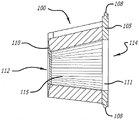
FIG. 1A illustrates a top plan view of an exemplary embodiment of a reusable air filter including an end cap, a base, and filter media;
FIG. 1B shows a cross-sectional view of the reusable air filter of FIG. 1A taken along line 1B-1B;
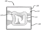
FIG. 1C shows a bottom plan view of the reusable air filter of FIG. 1A;
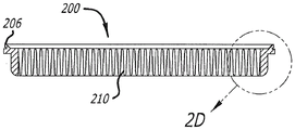
FIG. 2A shows a perspective view of an exemplary embodiment of a reusable air filter including a tray and filter media;
FIG. 2B shows a top plan view of the reusable air filter of FIG. 2A;
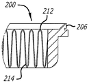
FIG. 2C shows a cross-sectional view of the reusable air filter of FIG. 2B taken along line 2C-2C;
FIG. 2D shows a close-up view of the reusable air filter shown in FIG. 2C;
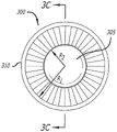
FIG. 3A shows a perspective view of an exemplary embodiment of a reusable air filter including an end cap, a base, and filter media;
FIG. 3B illustrates a top plan view of the reusable air filter shown in FIG. 3A;
FIG. 3C illustrates a cross-sectional view of the reusable air filter of FIG. 3A taken along line 3C-3C of FIG. 3B;
FIG. 3D shows a bottom plan view of the reusable air filter of FIG. 3A;
FIG. 4A illustrates a cross-sectional view of an exemplary embodiment of a reusable air filter including an end cap, a base, and filter media;
FIG. 4B shows a top plan view of the reusable air filter of FIG. 4A;
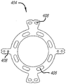
FIG. 4C illustrates a top plan view of an exemplary embodiment of a stiffening ring that may be incorporated into the end cap of the reusable air filter shown in FIG. 4A;
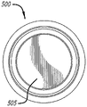
FIG. 5A illustrates a cross-sectional view of an exemplary embodiment of a cylindrical reusable air filter;
FIG. 5B shows a bottom plan view of the reusable air filter of FIG. 5A;
FIG. 5C shows a close-up view of the reusable air filter of FIG. 5A;
FIG. 5D illustrates a top plan view of the reusable air filter of FIG. 5A;
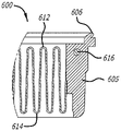
FIG. 6A shows a bottom plan view of an exemplary embodiment of a right angle trapezoidal reusable air filter including a tray and filter media;
FIG. 6B shows a cross-sectional view of the reusable air filter of FIG. 6A taken along line 6B-6B; and
FIG. 6C shows a close-up view of the reusable air filter shown in FIG. 6B.
While the disclosure is subject to various modifications and alternative forms, specific embodiments thereof have been shown by way of example in the drawings and will herein be described in detail. It should be understood, that the invention is not to be limited to the particular forms disclosed, but on the contrary, the intention is to cover all modifications, equivalents, and alternatives falling within the spirit and scope of the disclosure.
Detailed Description
In the following description, numerous specific details are set forth in order to provide a thorough understanding of the present disclosure. It will be apparent, however, to one skilled in the art that the invention disclosed herein may be practiced without these specific details. In other cases, a particular numerical reference, such as "first filter media," may be made. However, the particular numerical references should not be construed as a literal sequential order, but rather as "first filter media" being different from "second filter media". Accordingly, the specific details set forth are merely exemplary. The specific details may be varied and still be contemplated to be within the spirit and scope of the present disclosure. The term "connected" is defined to mean directly connected to the component or indirectly connected to the component through another component. Further, as used herein, the terms "about," "approximately," or "substantially" for any numerical value or range denote suitable dimensional tolerances that allow a portion or collection of components to function for their intended purpose as described herein.
In general, the present disclosure describes an apparatus and method for a reusable air filter configured to filter air conducted to an intake of an internal combustion engine. The air filter includes a filter media configured to pass an air flow and to capture particles flowing within the air flow. The filter media is desirably shaped and formed so as to provide an optimal filtration surface area within the confines of the air filter. The air filter may be configured to be mounted within an air intake box or secured to the interior of an engine compartment. It should be understood that embodiments of the present disclosure are not limited to the exact shapes shown, but may include many various generally cylindrical shapes, generally annular, oval, circular, curved, conical, or other closed perimeter shapes that provide a relatively large filtering surface area in a given volume of filter. Furthermore, embodiments as described herein are not limited to use as internal combustion engine filters, but may have applicability in other filtration systems that require handling large volumes of air.
Fig. 1A-1C illustrate an exemplary embodiment of a reusable air filter 100 according to the present disclosure. More specifically, fig. 1A shows a top plan view of a reusable air filter 100. As shown, the reusable air filter 100 includes an end cap 110, a base 105, and filter media 115 connected between the base and the end cap, the base 105 including an air inlet receiver 111 configured to receive an air inlet of an engine. The filter media 115 is generally configured to remove particulate matter and other contaminants from an incoming airflow. In some embodiments, the filter media may comprise paper, foam, cotton, woven fiberglass or other known filter materials, woven or non-woven materials, synthetic or natural, or any combination thereof. In some embodiments, the filter media may include a filter oil composition to enhance the air cleaning performance of the filter media. It is contemplated that reusable air filter 100 may be installed within an intake box (not shown). Preferably, the air intake box is constructed of a rigid material that is sufficiently durable and temperature resistant to maintain its configuration during installation and operation when connected with the air intake of the engine.
As best shown in FIG. 1B, the filter media 115 provides a region to pass the airflow and capture particles and other contaminants flowing with the airflow. The filter media 115 may be pleated or otherwise shaped or contoured to increase the filtration surface area for the airflow to be cleaned to pass through. In the illustrated embodiment of fig. 1A-1C, the filter media 115 comprises a generally cubic shape configured with wave-shaped sided features to occupy as much volume as possible within the intake box. Moreover, the filter media 115 is configured with rounded and/or curved edges to further increase the surface area for filtration purposes, and also to desirably increase the power output of the engine. As such, in one embodiment, it is contemplated that cube-shaped filter media 115 may be beneficial for vehicle applications requiring special hauling capacity and/or traction, such as, by way of non-limiting example, a heavy duty pick-up truck. In one embodiment, filter media 115 includes a first end 112 and a second end 114 such that first end 112 has a small diameter compared to a diameter of second end 114. Accordingly, the filter media 115 includes a diameter that tapers along the length of the filter media (extending from the second end 114 to the first end 112). In one embodiment, the filter media 115 tapers at an angle of substantially 31 degrees relative to the base 105.
In some embodiments, the filter media 115 may include 4 to 6 layers of cotton gauze sandwiched between a first outer wire mesh and a second inner wire mesh. It is contemplated that in some embodiments, the first and second wire mesh may be co-pleated with a cotton gauze. In one embodiment, the filter media 115 may have a pleat count of substantially 75 pleats, but the pleat count may vary depending on the application. Furthermore, the cotton may advantageously be treated with a suitably formulated filter oil composition which induces tackiness throughout the microscopic strands making up the filter medium. The cotton nature allows for a large amount of airflow and, when combined with the viscosity of the filter oil composition, creates a strong filter medium that presents little resistance to airflow through the air filter 100. Further details regarding the components that make up the Filter Media 115, as well as details regarding the Filter Oil composition, are disclosed in U.S. patent application serial No. 14/181,678 entitled "Air Box With Integrated Filter Media" filed on 16/2014 and U.S. patent application serial No. 14/701,163 entitled "Filter Oil Formulation" filed on 30/4 2015, each of which is incorporated herein by reference in its entirety.
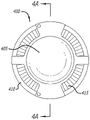
Fig. 1C shows a bottom plan view of the reusable air filter 100 showing the inlet receptacle 111 disposed in the base 105. The base 105 is generally configured to support the air filter 100 and provide an interface between the air filter 100 and an intake box connected to an air inlet (such as, but not limited to, an intake duct, turbocharger, manifold, etc.). As such, it is contemplated that the base 105 may include any of a variety of additional ridges or raised portions for optimal engagement with the intake box. The particular configuration of the base 105 and the size of the inlet receiver 111 depend on the particular make and model of vehicle in which the air filter 100 is to be used, and thus a very large number of configurations and sizes may be incorporated into the air filter 100 without departing from the scope of the present invention.
In the embodiment shown in FIG. 1C, the base 105 further includes a lip element 108 configured to mate with and/or otherwise connect with the air intake box. In some embodiments, the base 105 may include any of a variety of apertures to receive any fastener known in the art. Further, to support the air filter 100 within the intake box, any of a variety of suitable tabs, screws, and various insertion points may be provided on the base 105, but are not limited thereto. Thus, as will be understood by those skilled in the art, the configuration of the base 105 depends on the particular vehicle in which the reusable air filter 100 will be used.
It is contemplated that a user of reusable air filter 100 may periodically clean filter media 115 rather than replace reusable air filter 100 as is typical with conventional air filtration systems. In some embodiments, the method of cleaning the filter media 115 includes removing the reusable air filter 100 from the engine compartment, inserting a water hose through the inlet receiver 111 into the interior cavity of the filter, and spraying water to flush contaminants from the filter media 115. In some embodiments, the method of cleaning the reusable air filter 100 may include using a high pressure air duct instead of a water duct. In some embodiments, a method of cleaning the reusable air filter 100 may include spraying water onto the exterior of the filter media 115 such that water and contaminants drain from the exterior of the filter media 115. Other cleaning methods will be apparent to those skilled in the art without departing from the spirit and scope of the present disclosure.
Fig. 2A shows a perspective view of an exemplary embodiment of a reusable air filter 200, the reusable air filter 200 including a tray 205 defining filter media 210. The tray 205 includes a lip 206 that may be used, for example, to connect the reusable air filter 200 with an optional air induction box (or otherwise support the air filter within the engine compartment). Lip 206 may include any suitably designed hole, bracket, molded portion, protrusion, extension, angled bracket, hardware fastener, or any other similar device for supporting reusable air filter 200 within an intake box or engine compartment, but is not limited thereto. As will be appreciated, the particular fasteners will generally vary depending on the particular make and model of vehicle in which the reusable air filter 200 is used.
The filter media 210 is generally connected to the tray 205 and is configured to remove particulate matter and other contaminants from the incoming airflow. Filter media 210 is substantially similar to filter media 115 as shown in FIGS. 1A-1C, except that filter media 210 is provided in a flat or plate-like configuration. The filter media 210 may include paper, foam, cotton, woven fiberglass or other known filter materials, woven or unwoven materials, synthetic or natural, or any combination thereof. In some embodiments, the filter media 210 may include 4 to 6 layers of cotton gauze, which may be treated with the filter oil composition to enhance the air cleaning performance of the filter media 210. As described herein, the properties of cotton allow a large amount of airflow through the filter media 210, and when combined with the viscosity of the filter oil composition, create a strong filter media that exhibits relatively little resistance to airflow through the filter media. Additionally, the filter media 210 may include a pleated cotton gauze layer arranged in a generally sinusoidal configuration. In the illustrated embodiment of fig. 2C-2D, the sinusoidal configuration of filter media 210 includes a series of peaks 212 and valleys 214, wherein valleys 214 are relatively wider than peaks 212. It is contemplated that the peaks 212 provide relatively little resistance to airflow, while the valleys 214 provide a relatively large filtering surface area to capture particulate matter.
Also, in some embodiments, the tray 205 may include a rounded edge 208 configured to couple with an inner surface of the inlet box. It should be understood that although reusable air filter 200 is shown as having a substantially square shape with rounded edges 208, many other shapes may be used instead of square shapes, including trapezoids, rectangles, etc., alone or in combination with rounded edges 208, as non-limiting examples. Thus, in one embodiment, reusable air filter 200 has a width of substantially 11.82 inches and a length of approximately 12.49 inches, although a wide variety of other widths and lengths are contemplated.
It is contemplated that a user of reusable air filter 200 may periodically clean filter media 210 rather than replace reusable air filter 100 as is typical with conventional air filtration systems. The method of cleaning the reusable air filter 200 is substantially similar to the method of cleaning the reusable air filter 100 discussed in connection with fig. 1A-1C. In some embodiments, where the filter media 210 comprises a filter oil composition, a solvent may be used to remove oil from the filter media. Once the filter media 210 is free of oil and substantially dry, a properly formulated filter oil composition can be uniformly applied and allowed to wick into the filter media. Further details regarding suitable FILTER OIL compositions are disclosed in U.S. patent application serial No. 14/701,163, entitled FILTER OIL FORMULATION, which is disclosed above and incorporated by reference herein above. Various other cleaning methods will be apparent to those skilled in the art without departing from the spirit and scope of the present disclosure.
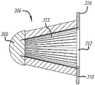
Fig. 3A-3D illustrate an exemplary embodiment of a reusable air filter 300 similar to reusable air filter 100 discussed with reference to fig. 1A-1C. As best shown in FIG. 3A, reusable air filter 300 includes end cap 305, base 310, and filter media 315 connected therebetween. End cap 310 preferably includes a hemispherical shape configured to direct airflow into filter media 315. In one embodiment, the end cap 305 has a diameter of substantially 4.03 inches and a height of substantially 1.76 inches. Further, in one embodiment, reusable air filter 300 has a height of substantially 8.01 inches, and a diameter of substantially 8.16 inches. It should be understood, however, that the particular diameter and height of the end cap 305, as well as the diameter and height of the overall reusable air filter 300, will depend on the particular application for which the air filter is intended to be used.
Fig. 3B shows a top plan view of the reusable air filter 300. As shown, the base 310 has a radius R1Which is greater than the radius R of the end cap 3052. In one embodiment, the logo may be etched or otherwise disposed on the end cap 305. As shown in fig. 3C, filter media 315 preferably comprises a pleated cotton gauze layer to increase the filtration surface area within the confines of air filter 300, while also desirably increasing the power output of the engine through reduced intake resistance. The cotton may advantageously be treated with a suitably formulated filter oil composition that induces tackiness throughout the microscopic strands that make up the filter media 315. As described herein, the properties of cotton allow for a large amount of air flow and, when combined with the viscosity of the filter oil composition, result in a strong filter medium that ensures a high degree of air filtration.
The base 310 is generally configured to support the air filter 300 and provide an interface between the air filter and the air inlet of the engine. It is contemplated that the air inlet may be, but is not limited to, an intake manifold, a turbocharger, a manifold, and the like. As best shown in fig. 3D, the base 310 includes an inlet receiver 312 that facilitates connecting the air filter 300 with an air inlet of an engine. In addition, the base 310 may include a lip 316 that facilitates attachment of the air filter 300 within the intake box or elsewhere in the engine compartment. Lip 316 may include any suitably designed hole, bracket, molded portion, protrusion, extension, angled bracket, hardware fastener, or any other similar means for securely retaining reusable air filter 300 within the engine compartment and/or intake box. Further, it is contemplated that the base 310 may include any of a variety of additional ridges or raised portions to best engage the air intake of the engine. The particular configuration of the base 310 and the diameter of the inlet receiver 312 depend on the particular make and model of vehicle in which the air filter 300 is to be used, and thus a wide variety of configurations and diameters may be incorporated into the air filter 300 without departing from the scope of the present disclosure.
As described above with respect to fig. 1A-2D, a user of reusable air filter 300 may periodically clean filter media 315 rather than replace reusable air filter 300. The method of cleaning the reusable air filter 300 is substantially similar to the method of cleaning the reusable air filter 200 discussed in connection with fig. 2A-2D. It is contemplated that various other cleaning methods will be apparent to those skilled in the art without departing from this disclosure.
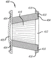
Fig. 4A-4C illustrate an exemplary embodiment of a reusable air filter 400 that includes a reinforced end cap 405, a base 410, and filter media 415. Fig. 4A shows a cross-sectional view of a reusable air filter 400. Reusable air filter 400 is generally circular and the diameter of filter media 415 near base 410 is larger than the diameter near reinforced end cap 405, making the filter media conical. However, as best shown in fig. 4B, the reinforced end cap 405 includes a portion having a diameter substantially similar to the diameter of the base 410. In one embodiment, a logo may be etched and/or otherwise disposed on the reinforced end cap 405. In some embodiments, the reinforced end cap 405 and the base 410 may be constructed of polyurethane or any other similar rigid material, but are not limited thereto. Preferably, the reinforcement ring 404 shown in FIG. 4C is disposed within the material comprising the reinforced end cap 405 to provide structural integrity to the reusable air filter 400. In one embodiment, a plurality of holes 408 are provided in the reinforcement ring 404 to facilitate bonding the material comprising the reinforced end cap 405 with the reinforcement ring. As will be appreciated, the particular number and arrangement of the plurality of apertures 408 is not limited to those shown and discussed herein, but the number and arrangement of the apertures 408 may vary without limitation.
The filter media 415 preferably comprises a layer of pleated cotton gauze, which may be advantageously treated with a suitably formulated filter oil composition that imparts tackiness throughout the microscopic strands that comprise the filter media. As described herein, the properties of cotton allow for a large amount of air flow and, when combined with the viscosity of the filter oil composition, result in a strong filter medium that ensures a high degree of air filtration. Further, the filter media 415 may be periodically cleaned in a substantially similar manner as explained herein with respect to the reusable air filters 100, 200. The method of cleaning the reusable air filter 400 is substantially similar to the method of cleaning the reusable air filter 200 discussed in connection with fig. 2A-2D. It is contemplated that various other cleaning methods will be apparent to those skilled in the art without departing from this disclosure.
As shown in the embodiment of fig. 4A, a slight hemispherical shape may be incorporated into the reinforced end cap 405. In some embodiments, the slight hemispherical shape may contribute to the structural integrity of the reinforced end cap 405 in particular, and of the air filter 400 as a whole. The base 410 is generally configured to support the air filter 400 and provide an interface between the air filter and the air inlet of the engine. For example, the base 410 may be connected with an intake pipe, a turbocharger, a manifold, etc., but is not limited thereto. As best shown in fig. 4A, the base 410 includes an inlet receptacle 412 that facilitates directing airflow from the filter media 415 into an air inlet of the engine. Further, the base 410 may include a lip 416, the lip 416 configured to connect the air filter 400 with an intake box or other location in the engine compartment. Lip 416 may include any suitably designed hole, bracket, molded portion, protrusion, extension, angled bracket, hardware fastener, or any other similar means for supporting reusable air filter 400 within the engine compartment and/or intake box. In some embodiments, the base 410 may include any of a variety of additional ridges or raised portions to best engage with the air inlet of the engine. The particular configuration of the base 410 and the diameter of the opening 412 depend on the particular make and model of vehicle in which the air filter 400 is used, and thus a variety of configurations and diameters may be incorporated into the air filter 400 without departing from the scope of the present disclosure.
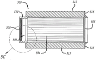
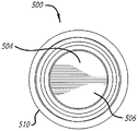
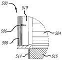
Fig. 5A-5D illustrate an exemplary embodiment of a substantially cylindrical reusable air filter 500 that includes an end cap 505, a base 510, and filter media 515. The filter media 515 preferably comprises a pleated cotton gauze layer configured to increase the filtration surface area. The filter media 515 may be configured to be treated with a suitable filter oil composition in order to enhance the filtering performance of the air filter while also producing a relatively greater engine power output, as described herein. In one embodiment, the logo can be etched and/or otherwise disposed on the end cap 505. In the embodiment shown in fig. 5A-5D, the base 510 has substantially the same radius as the end cap 505, thereby giving the reusable air filter 500 the cylindrical shape described above. It should be understood, however, that reusable air filter 500 is not limited to the exact shape shown, but may include a wide variety of generally cylindrical shapes, generally annular, oval, circular, curved, conical, or other closed perimeter shapes that provide a relatively large filtering surface area in a given volume of the filter.
As best shown in fig. 5A, the inlet receiver 506 provides an opening into the interior 504 of the air filter 500. The inlet receiver 506 is configured to be connected to an air inlet of the engine (such as, for example, an intake air duct, a turbocharger, a manifold, etc.). A series of grooves 508 are disposed about an inner periphery of the inlet receiver 506 and are configured to facilitate an air-tight connection of the base 510 with an air intake of an engine. As such, it is contemplated that the base 510 may include any of a variety of additional ridges or raised portions for optimal engagement with the air inlet. The particular configuration of the base 510 and the diameter of the inlet receiver 506 depend on the particular make and model of vehicle in which the air filter 500 is used, and thus a wide variety of configurations and diameters may be incorporated into the air filter 500 without departing from the scope of the present disclosure.
The filter media 515 is preferably fixedly connected between the base 510 and the end cap 505. As best shown in fig. 5C, the base 510 is connected to the filter media 515 by a flange 514. A similar flange 516 connects the end cap 505 with the filter media 515. However, it is contemplated that any of a variety of suitable structures, fasteners, or adhesives may be used to retain the filter media 515 between the base 510 and the end cap 505. As such, in some embodiments, any suitably designed holes, brackets, molded portions, protrusions, extensions, angled brackets, hardware fasteners, or any other similar means may be incorporated into the reusable air filter 500 for connecting the filter media 515 between the end caps 505 and the base 510, but is not limited to such.
Fig. 6A-6C illustrate an exemplary embodiment of a flat, plate-shaped reusable air filter 600. Reusable air filter 600 is substantially similar to reusable air filter 200 shown in fig. 2A-2D 2, except that air filter 600 has a right trapezoid shape. The reusable air filter 600 generally includes a filter media 610, the filter media 610 being defined by a tray 605. The filter media 610 preferably comprises a pleated cotton gauze layer configured to increase the filtration surface area within the tray 605. The cotton can advantageously be treated with a suitably formulated filter oil composition that creates tackiness throughout the microscopic strands that make up the filter media. As described above, the filter media 610 comprising cotton in combination with the filter oil composition provides a relatively large amount of filtered air flow.
As shown, and best seen in fig. 6B-6C, the filter media 610 includes a series of pleated cotton scrim layers disposed in a generally sinusoidal arrangement. As best shown in fig. 6C, the sinusoidal arrangement of filter media 610 includes peaks 612 and valleys 614 configured to provide a filtration surface area that is substantially greater than the cross-sectional area of tray 605. The large filter surface area exhibits relatively less resistance to airflow through the filter media 610, resulting in a proportionally greater engine power output. In one embodiment, the peaks 612 and valleys 614 have a pleat height (peak-to-peak) of substantially 1.95 inches. It should be understood, however, that the pleat height, as well as the overall size of the reusable air filter 600, will depend on the particular engine application for which the reusable air filter is intended to be used.
As best shown in fig. 6B-6C, the sides of the tray 605 are reinforced by support bars 616, the support bars 616 being embedded within the material making up the tray. It will be appreciated that the support bar 616 serves to prevent the sides of the tray 605 from flexing under air pressure when connected to the inlet box, particularly when subjected to engine heating. In addition, a lip 606 is provided along the topmost edge of the tray 605 and is configured to facilitate connection of the reusable air filter 600 within an air intake box or within a suitable air duct. The lip 606 is preferably constructed of a pliable material and is configured to create an air-tight seal with a mounting surface within the intake box, thereby ensuring that all air flowing through the intake box or duct is directed through the filter media 610. It is contemplated that any suitably designed hole, bracket, molded portion, protrusion, extension, angled bracket, hardware fastener, or any other similar means for advantageously securely retaining reusable air filter 600 within an air induction box may be implemented in addition to lip 606. It should be understood, however, that the specific fasteners will vary depending on the specific make and model of vehicle in which the reusable air filter 600 is used and the air intake box configuration.
It is contemplated that a user of any of the above-described reusable air filters may periodically clean the filter media of the air filter, rather than replacing the entire air filter as is typical with conventional air filtration systems. It is contemplated that the air filter may be removed from any of the air intake boxes discussed herein, and then the water lines may be used to flush contaminants from the filter media. In some embodiments, where the filter media includes a filter oil composition, a solvent may be used to remove oil from the filter media, thereby cleaning the air filter and preparing it for reuse. Once the filter media is completely dry, a properly formulated filter oil composition can be applied uniformly and allowed to wick into the filter media. The filter oil composition is discussed in more detail in U.S. patent application serial No. 14/701,163, which is incorporated by reference above. Various other cleaning methods will be apparent to those skilled in the art without departing from the spirit and scope of the present disclosure.
While the invention has been described in terms of specific variations and illustrative figures, those of ordinary skill in the art will recognize that the invention is not limited to the variations or figures described. Additionally, where methods and steps described above indicate certain events occurring in a certain order, those of ordinary skill in the art will recognize that the order of certain steps may be modified and that such modifications are in accordance with the variations of the present invention. In addition, certain steps may be performed concurrently in parallel processing, where possible, as well as performed sequentially as described above. This patent is intended to cover such modifications as would fall within the spirit of the disclosure or equivalent to the inventions in the claims. Accordingly, the present disclosure should be understood as not being limited by the particular embodiments described herein, but only by the scope of the appended claims.
Claims (8)
1. A reusable air filter for filtering air conducted to an intake of an internal combustion engine, comprising:
a filter media configured to pass the gas stream and capture particles flowing within the gas stream; and
a tray configured to supportively hold a filter media,
wherein the filter media comprises one or more layers of cotton scrim arranged in a sinusoidal arrangement comprising a series of peaks and valleys so as to provide a filtration surface area greater than a perimeter area of the filter media,
wherein the filter media comprises a series of peaks and valleys, and wherein the valleys are wider than the peaks such that the peaks provide relatively little resistance to airflow and the valleys provide a relatively large filtering surface area to capture particulate matter,
also included are support rods embedded within the material comprising the tray and configured to prevent the sides of the tray from bending under air pressure when connected with an intake box of an internal combustion engine.
2. The reusable air filter of claim 1, wherein the tray is configured to support the air filter within an intake box connected to an air inlet of an internal combustion engine, the air inlet being any one of an intake manifold, a turbocharger, and a manifold of an internal combustion engine.
3. The reusable air filter of claim 1, wherein the tray includes rounded edges disposed at corner portions of any one of a square shape, a rectangular shape, and a trapezoidal shape.
4. The reusable air filter of claim 1, wherein the tray includes a lip configured to establish an air-tight seal with a mounting surface disposed within an intake box connected with an air inlet of an internal combustion engine.
5. A method for a reusable air filter according to any of claims 1-4 for filtering air directed to an intake of an internal combustion engine, comprising:
configuring a cleanable filter medium to capture particles flowing in a gas stream;
forming the cleanable filter media into a shape that facilitates connecting the reusable air filter with the intake box such that the entire airflow passes through the filter media;
configuring the contour of the cleanable filter media to provide a filter surface area that is greater than the area of the shape; and
the filter media is attached to one or more support structures that maintain the shape of the filter media.
6. The method of claim 5, wherein the forming further comprises forming the cleanable filter media into any one of a square shape, a rectangular shape, and a trapezoidal shape.
7. The method of claim 6, wherein the connecting further comprises implementing the support structure as a tray configured to support an air filter within an intake box connected with an air inlet of an internal combustion engine, the air inlet being any one of an intake duct, a turbocharger, and a manifold of the internal combustion engine.
8. The method of claim 7, wherein the attaching further comprises embedding support rods within the material comprising the tray to prevent sides of the tray from bending under air pressure when attached to an intake box of an internal combustion engine.
Applications Claiming Priority (4)
| Application Number | Priority Date | Filing Date | Title |
|---|---|---|---|
| US201662312930P | 2016-03-24 | 2016-03-24 | |
| US62/312930 | 2016-03-24 | ||
| PCT/US2017/024113 WO2017165829A1 (en) | 2016-03-24 | 2017-03-24 | Reusable air filter system and method |
| CN201780032058.6A CN109641168B (en) | 2016-03-24 | 2017-03-24 | Reusable air filter system and method |
Related Parent Applications (1)
| Application Number | Title | Priority Date | Filing Date |
|---|---|---|---|
| CN201780032058.6A Division CN109641168B (en) | 2016-03-24 | 2017-03-24 | Reusable air filter system and method |
Publications (1)
| Publication Number | Publication Date |
|---|---|
| CN114768392A true CN114768392A (en) | 2022-07-22 |
Family
ID=59896863
Family Applications (2)
| Application Number | Title | Priority Date | Filing Date |
|---|---|---|---|
| CN201780032058.6A Active CN109641168B (en) | 2016-03-24 | 2017-03-24 | Reusable air filter system and method |
| CN202210458997.XA Pending CN114768392A (en) | 2016-03-24 | 2017-03-24 | Reusable air filter system and method |
Family Applications Before (1)
| Application Number | Title | Priority Date | Filing Date |
|---|---|---|---|
| CN201780032058.6A Active CN109641168B (en) | 2016-03-24 | 2017-03-24 | Reusable air filter system and method |
Country Status (11)
| Country | Link |
|---|---|
| US (3) | US10456727B2 (en) |
| EP (2) | EP4070874A1 (en) |
| KR (2) | KR102393874B1 (en) |
| CN (2) | CN109641168B (en) |
| AU (2) | AU2017238803B2 (en) |
| BR (1) | BR112018069419B1 (en) |
| CA (1) | CA3018376C (en) |
| ES (1) | ES2913059T3 (en) |
| MX (1) | MX2018011490A (en) |
| PH (1) | PH12018502022A1 (en) |
| WO (1) | WO2017165829A1 (en) |
Families Citing this family (5)
| Publication number | Priority date | Publication date | Assignee | Title |
|---|---|---|---|---|
| WO2017079191A1 (en) * | 2015-11-04 | 2017-05-11 | Parker-Hannifin Corporation | Wave seal for filter element |
| CN109641168B (en) * | 2016-03-24 | 2022-08-12 | K&N工程公司 | Reusable air filter system and method |
| US11506155B2 (en) * | 2018-10-27 | 2022-11-22 | K&N Engineering, Inc. | Engine control unit cooling air box |
| USD936198S1 (en) * | 2020-01-22 | 2021-11-16 | Dbg Group Investments, Llc | Ozone plate for an air purification device |
| CN112392632A (en) * | 2020-11-10 | 2021-02-23 | 一汽解放汽车有限公司 | Oil bath type air filter |
Citations (11)
| Publication number | Priority date | Publication date | Assignee | Title |
|---|---|---|---|---|
| US5098767A (en) * | 1989-02-15 | 1992-03-24 | Pall Corporation | Filter device with micropleats and macropleats |
| US6203592B1 (en) * | 1999-04-20 | 2001-03-20 | Dana Corporation | Filter media configuration |
| CN1568217A (en) * | 2001-10-12 | 2005-01-19 | 3M创新有限公司 | Interconnected filter frame and filter framing method |
| US20090249755A1 (en) * | 2008-04-08 | 2009-10-08 | O'leary Richard R | Air filter |
| CN101888892A (en) * | 2007-12-06 | 2010-11-17 | 日东电工株式会社 | Air filter |
| CN102725046A (en) * | 2010-01-19 | 2012-10-10 | 康斐尔集团 | Filter unit |
| US20130062276A1 (en) * | 2010-09-07 | 2013-03-14 | Cummins Filtration Ip Inc. | Filter and filter media having reduced restriction |
| CN202860322U (en) * | 2012-06-21 | 2013-04-10 | 深圳奇滨电子有限公司 | Air purifying filtering paper |
| CN203540252U (en) * | 2013-11-22 | 2014-04-16 | 浙江圣峰汽车部件有限公司 | Filter paper core with bump style knurls |
| CN204710000U (en) * | 2015-05-18 | 2015-10-21 | 美埃(中国)环境净化有限公司 | New-type plate filter |
| CN105221305A (en) * | 2014-02-16 | 2016-01-06 | K&N工程公司 | There is the air tank of Integral filtering medium |
Family Cites Families (40)
| Publication number | Priority date | Publication date | Assignee | Title |
|---|---|---|---|---|
| US4349363A (en) * | 1980-10-27 | 1982-09-14 | Incom International Inc. | Filter element ledge gasket |
| US4473471A (en) * | 1982-09-13 | 1984-09-25 | Purolator Inc. | Filter sealing gasket with reinforcement ring |
| US5238717A (en) * | 1991-04-26 | 1993-08-24 | Pall Corporation | End caps for filter elements |
| US5509950A (en) * | 1992-07-11 | 1996-04-23 | Minnesota Mining And Manufacturing Company | Filter device for the filtration of gases and/or fluids |
| US5484466A (en) * | 1994-02-14 | 1996-01-16 | Baldwin Filters, Inc. | Air filter element with radial seal sealing gasket |
| US5674302A (en) * | 1994-07-12 | 1997-10-07 | Nippondenso Co., Ltd. | Automobile filter element |
| KR0168811B1 (en) * | 1996-08-20 | 1999-01-15 | 윤종용 | Control method and apparatus for lamp lighting of a refrigerator |
| DE19757423C1 (en) * | 1997-12-23 | 1998-11-26 | Freudenberg Carl Fa | Filter insert |
| US6136076A (en) * | 1998-10-16 | 2000-10-24 | Air-Maze Corporation | Air/oil separator with molded top sealing flange |
| DE19856520A1 (en) * | 1998-12-08 | 2000-06-15 | Mann & Hummel Filter | Housing, in particular filter housing with filter insert |
| ITBO20000024A1 (en) * | 2000-01-25 | 2001-07-25 | Bmc Srl | INTERNAL COMBUSTION ENGINE FUEL AIR FILTER. |
| US6447567B1 (en) * | 2001-05-14 | 2002-09-10 | Baldwin Filters, Inc. | Air filter element with integral radial seal gasket |
| US6866693B2 (en) * | 2002-06-06 | 2005-03-15 | Shuetsutechnica Co., Ltd. | Washable air filter for internal combustion engine |
| US7041158B1 (en) * | 2003-05-14 | 2006-05-09 | Wix Filtration Corp. | Pre-molded air filter end cap and method of manufacturing an air filter |
| EP2223729A1 (en) * | 2003-07-18 | 2010-09-01 | Mann + Hummel Gmbh | Filter element, especially for cleaning combustion air |
| US20050022490A1 (en) * | 2003-07-30 | 2005-02-03 | Ruey-Fa Huang | Vehicle air cleaner |
| WO2005026522A1 (en) * | 2003-09-08 | 2005-03-24 | K & N Engineering, Inc. | Air box lid having an integrated filter |
| US20050076621A1 (en) * | 2003-10-09 | 2005-04-14 | Yung-Yu Chang | Air filter for an internal combustion engine |
| GB0326790D0 (en) * | 2003-11-18 | 2003-12-24 | Madison Filter 981 Ltd | Filter cloth retention apparatus |
| WO2005079954A1 (en) * | 2004-02-17 | 2005-09-01 | Donaldson Company, Inc. | Air cleaner arrangements; serviceable filter elements; and, methods |
| PL3470130T3 (en) * | 2004-03-24 | 2022-01-17 | Donaldson Company, Inc. | Air filter cartridge and air cleaner arrangement |
| US20050217625A1 (en) * | 2004-04-05 | 2005-10-06 | Advanced Flow Engineering, Inc. | Heat shielded air intake system |
| DE202005009468U1 (en) * | 2005-06-15 | 2006-10-19 | Mann + Hummel Gmbh | filter element |
| DE202005009836U1 (en) | 2005-06-21 | 2006-10-26 | Mann + Hummel Gmbh | filter element |
| US20070163945A1 (en) * | 2006-01-19 | 2007-07-19 | Baldwin Filters, Inc. | Method and apparatus for reinforcing a tubular-shaped sealing collar extending from a filter apparatus |
| US8102896B2 (en) * | 2006-10-04 | 2012-01-24 | Nokia Corporation | Method and apparatus for multiplexing control and data channel |
| DE102007017091A1 (en) * | 2007-04-10 | 2008-10-16 | Mahle International Gmbh | Ring filter element |
| WO2009015684A1 (en) * | 2007-07-27 | 2009-02-05 | Mann+Hummel Gmbh | Air filter, especially for internal combustion engines in motor vehicles, and method for the production of such an air filter |
| CN201096042Y (en) * | 2007-09-08 | 2008-08-06 | 刘跃峰 | Pressurizing air filter |
| DE102012000482A1 (en) * | 2012-01-13 | 2013-07-18 | Mann + Hummel Gmbh | Air filter element and air filter |
| DE102012012039A1 (en) * | 2012-06-19 | 2013-12-19 | Man Truck & Bus Ag | Intake system for internal combustion engines |
| US11331615B2 (en) * | 2013-03-15 | 2022-05-17 | K&N Engineering, Inc. | Air filter |
| US9010039B2 (en) * | 2013-07-02 | 2015-04-21 | Rite-Hite Holding Corporation | Weather barrier apparatuses for sealing or sheltering vehicles at loading docks |
| US20150075123A1 (en) * | 2013-09-13 | 2015-03-19 | S&B Filters, Inc. | Air filter and air box for engines |
| US9410510B2 (en) * | 2014-03-24 | 2016-08-09 | Caterpillar Inc. | Air cleaner arrangement |
| DE102014006117B4 (en) * | 2014-04-29 | 2017-12-21 | Mann + Hummel Gmbh | Filter element, in particular for gas filtration |
| US10883455B2 (en) * | 2015-10-28 | 2021-01-05 | K&N Engineering, Inc. | Curved base air cleaner |
| CN109641168B (en) * | 2016-03-24 | 2022-08-12 | K&N工程公司 | Reusable air filter system and method |
| US10661215B2 (en) * | 2016-08-03 | 2020-05-26 | K&N Engineering, Inc. | Cone air filter |
| US10744440B2 (en) * | 2016-09-26 | 2020-08-18 | K&N Engineering, Inc. | Flangeless air filter |
-
2017
- 2017-03-24 CN CN201780032058.6A patent/CN109641168B/en active Active
- 2017-03-24 KR KR1020187030221A patent/KR102393874B1/en active IP Right Grant
- 2017-03-24 AU AU2017238803A patent/AU2017238803B2/en active Active
- 2017-03-24 CA CA3018376A patent/CA3018376C/en active Active
- 2017-03-24 EP EP22170088.3A patent/EP4070874A1/en not_active Withdrawn
- 2017-03-24 CN CN202210458997.XA patent/CN114768392A/en active Pending
- 2017-03-24 US US15/469,198 patent/US10456727B2/en active Active
- 2017-03-24 EP EP17771274.2A patent/EP3433004B1/en active Active
- 2017-03-24 BR BR112018069419-3A patent/BR112018069419B1/en active IP Right Grant
- 2017-03-24 KR KR1020227014479A patent/KR102562562B1/en active IP Right Grant
- 2017-03-24 ES ES17771274T patent/ES2913059T3/en active Active
- 2017-03-24 WO PCT/US2017/024113 patent/WO2017165829A1/en active Application Filing
- 2017-03-24 MX MX2018011490A patent/MX2018011490A/en unknown
-
2018
- 2018-09-21 PH PH12018502022A patent/PH12018502022A1/en unknown
-
2019
- 2019-09-25 US US16/582,533 patent/US11383194B2/en active Active
-
2022
- 2022-07-01 US US17/856,331 patent/US20220331731A1/en active Pending
- 2022-09-27 AU AU2022241476A patent/AU2022241476A1/en active Pending
Patent Citations (11)
| Publication number | Priority date | Publication date | Assignee | Title |
|---|---|---|---|---|
| US5098767A (en) * | 1989-02-15 | 1992-03-24 | Pall Corporation | Filter device with micropleats and macropleats |
| US6203592B1 (en) * | 1999-04-20 | 2001-03-20 | Dana Corporation | Filter media configuration |
| CN1568217A (en) * | 2001-10-12 | 2005-01-19 | 3M创新有限公司 | Interconnected filter frame and filter framing method |
| CN101888892A (en) * | 2007-12-06 | 2010-11-17 | 日东电工株式会社 | Air filter |
| US20090249755A1 (en) * | 2008-04-08 | 2009-10-08 | O'leary Richard R | Air filter |
| CN102725046A (en) * | 2010-01-19 | 2012-10-10 | 康斐尔集团 | Filter unit |
| US20130062276A1 (en) * | 2010-09-07 | 2013-03-14 | Cummins Filtration Ip Inc. | Filter and filter media having reduced restriction |
| CN202860322U (en) * | 2012-06-21 | 2013-04-10 | 深圳奇滨电子有限公司 | Air purifying filtering paper |
| CN203540252U (en) * | 2013-11-22 | 2014-04-16 | 浙江圣峰汽车部件有限公司 | Filter paper core with bump style knurls |
| CN105221305A (en) * | 2014-02-16 | 2016-01-06 | K&N工程公司 | There is the air tank of Integral filtering medium |
| CN204710000U (en) * | 2015-05-18 | 2015-10-21 | 美埃(中国)环境净化有限公司 | New-type plate filter |
Non-Patent Citations (3)
| Title |
|---|
| 丁根宝: "《铸造工艺学 下》", 机械工业出版社, pages: 80 * |
| 王顺亭: "《树脂基复合材料:材料选择、模具制作、工艺设计》", 30 June 1997, 中国建材工业出版社, pages: 141 * |
| 陈世敏: "《除尘技术与设备》", 30 June 1988, 人民邮电出版社, pages: 181 * |
Also Published As
| Publication number | Publication date |
|---|---|
| BR112018069419B1 (en) | 2023-12-12 |
| EP3433004B1 (en) | 2022-04-27 |
| EP3433004A1 (en) | 2019-01-30 |
| US11383194B2 (en) | 2022-07-12 |
| CA3018376C (en) | 2022-08-16 |
| WO2017165829A1 (en) | 2017-09-28 |
| AU2022241476A1 (en) | 2022-10-20 |
| KR20180132716A (en) | 2018-12-12 |
| US20220331731A1 (en) | 2022-10-20 |
| KR102393874B1 (en) | 2022-05-03 |
| AU2017238803A1 (en) | 2018-10-04 |
| BR112018069419A2 (en) | 2019-01-22 |
| CN109641168A (en) | 2019-04-16 |
| EP3433004A4 (en) | 2019-11-13 |
| US20200016525A1 (en) | 2020-01-16 |
| KR102562562B1 (en) | 2023-08-03 |
| KR20220062138A (en) | 2022-05-13 |
| MX2018011490A (en) | 2019-08-16 |
| CN109641168B (en) | 2022-08-12 |
| PH12018502022A1 (en) | 2019-03-04 |
| US20170274313A1 (en) | 2017-09-28 |
| US10456727B2 (en) | 2019-10-29 |
| ES2913059T3 (en) | 2022-05-31 |
| EP4070874A1 (en) | 2022-10-12 |
| CA3018376A1 (en) | 2017-09-28 |
| AU2017238803B2 (en) | 2022-09-29 |
Similar Documents
| Publication | Publication Date | Title |
|---|---|---|
| CN109641168B (en) | Reusable air filter system and method | |
| US20220243689A1 (en) | Air box with integrated filter media | |
| US10378491B2 (en) | Aircharger air intake system and method | |
| US20230364543A1 (en) | Air filter precleaner | |
| KR102439990B1 (en) | Super-pleated vehicle air filter | |
| US20210180547A1 (en) | Space optimizing air filter |
Legal Events
| Date | Code | Title | Description |
|---|---|---|---|
| PB01 | Publication | ||
| PB01 | Publication | ||
| SE01 | Entry into force of request for substantive examination | ||
| SE01 | Entry into force of request for substantive examination |