CN114166252B - Comprehensive positioning precision testing method for industrial robot integrated system - Google Patents
Comprehensive positioning precision testing method for industrial robot integrated system Download PDFInfo
- Publication number
- CN114166252B CN114166252B CN202210124693.XA CN202210124693A CN114166252B CN 114166252 B CN114166252 B CN 114166252B CN 202210124693 A CN202210124693 A CN 202210124693A CN 114166252 B CN114166252 B CN 114166252B
- Authority
- CN
- China
- Prior art keywords
- industrial robot
- plate
- positioning
- standard
- standard plate
- Prior art date
- Legal status (The legal status is an assumption and is not a legal conclusion. Google has not performed a legal analysis and makes no representation as to the accuracy of the status listed.)
- Active
Links
Images


Classifications
-
- G—PHYSICS
- G01—MEASURING; TESTING
- G01C—MEASURING DISTANCES, LEVELS OR BEARINGS; SURVEYING; NAVIGATION; GYROSCOPIC INSTRUMENTS; PHOTOGRAMMETRY OR VIDEOGRAMMETRY
- G01C25/00—Manufacturing, calibrating, cleaning, or repairing instruments or devices referred to in the other groups of this subclass
Landscapes
- Engineering & Computer Science (AREA)
- Manufacturing & Machinery (AREA)
- Physics & Mathematics (AREA)
- General Physics & Mathematics (AREA)
- Radar, Positioning & Navigation (AREA)
- Remote Sensing (AREA)
- Manipulator (AREA)
Abstract
The application discloses a comprehensive positioning precision testing method for an industrial robot integrated system, which comprises the following steps: placing a calibration plate on a plane with the flatness not lower than 0.05 mm/m; the calibration plate is provided with a plurality of polygonal grooves and a plurality of strip-shaped grooves; determining a reference point of each polygonal groove; mounting a standard plate at the flange end of the industrial robot; the shape of the standard plate is the same as that of the polygonal groove, and the side end of the standard plate is used for being butted with the strip-shaped groove; moving the standard plate to the reference point by operating the industrial robot, and sequentially enabling the front surface of the standard plate to be correspondingly matched with the corresponding polygonal grooves; adjusting the position and the posture of the industrial robot to enable the standard plate to be perpendicular to the calibration plate; the operating industrial robot moves the standard plate, so that different sides of the standard plate are sequentially and oppositely closed to the corresponding strip-shaped grooves.
Description
Technical Field
The application relates to the technical field of industrial robot precision detection, in particular to a comprehensive positioning precision testing method for an industrial robot integrated system.
Background
An industrial robot is a robot applied to production processes and environments and is characterized in that the robot replaces a human to do some long-time operation which is monotonous, frequent and repeated in a structured environment. The shape of the industrial robot is various, and the industrial robot is based on adapting to the field use environment and functions and is not limited to the shape of a human body. In recent years, the industrial robot industry has been developed vigorously, and more industrial robots are used in production lines for object transportation, component assembly, machining, and the like instead of human labor. At this stage, china has become the largest industrial robot market worldwide. However, because the domestic robot has unstable performance and reliability, the domestic robot is mostly applied to the fields of transportation, loading and unloading. The reason for this phenomenon is that, in the face of a more complex industrial robot system, the quality and performance detection for the robot measurement system in China is still in the starting stage, and the test repeatability and traceability of the related detection method are poor, which is not favorable for the correct assessment of the performance of the industrial robot.
The existing industrial robot precision testing method lacks some auxiliary means of standardized devices, so that the state of a processing surface needs to be considered during detection, repeatable verification cannot be carried out, the accuracy and reliability of positioning precision data after testing are low, most domestic robot manufacturers cannot carry out testing according to two standards of GB/T12642-.
Disclosure of Invention
The application mainly aims to provide a comprehensive positioning precision testing method for an industrial robot integrated system, and aims to solve the technical problems of low accuracy and reliability of positioning precision data after the existing industrial robot precision testing method tests.
In order to achieve the above object, the present application provides a method for testing the comprehensive positioning accuracy of an industrial robot integrated system, comprising the following steps:
placing a calibration plate on a plane with the flatness not lower than 0.05 mm/m; the calibration plate is provided with a plurality of polygonal grooves and a plurality of strip-shaped grooves;
determining a reference point of each polygonal groove;
installing a standard plate at the flange end of the industrial robot; the shape of the standard plate is the same as that of the polygonal groove, and the side end of the standard plate is used for being butted with the strip-shaped groove;
the operating industrial robot moves the standard plate to approach the datum point, so that the front surface of the standard plate is sequentially matched with the corresponding polygonal grooves, and if the standard plate and the polygonal grooves are matched, the visual measurement subsystem of the industrial robot is judged to pass detection;
adjusting the position and the posture of the industrial robot to enable the standard plate to be perpendicular to the calibration plate;
and operating the industrial robot to move the standard plate, so that different sides of the standard plate are sequentially in butt joint with the corresponding strip-shaped grooves, and if the standard plate and the strip-shaped grooves can be in butt joint, judging that the pose adjusting subsystem of the industrial robot passes detection.
Optionally, the calibration plate is further provided with a plurality of positioning holes, and the hole center lines of the plurality of positioning holes are not parallel to each other;
the operating industrial robot moves the standard plate to enable the side end of the standard plate to be sequentially matched with the corresponding strip-shaped groove, if the standard plate and the strip-shaped groove are matched, the operating industrial robot further comprises the following steps after the step of detecting the vision measuring subsystem of the industrial robot is judged to pass through:
removing the standard plate from the flange end of the industrial robot;
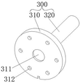
installing a standard rod at the flange end of the industrial robot; the standard rod comprises a mounting plate connected with a flange end of the industrial robot, the mounting plate is connected with a positioning rod, and the positioning rod is used for being matched with the positioning hole;
and operating the industrial robot to move the standard rods, enabling the positioning rods to be sequentially aligned with the corresponding positioning holes, and judging that the vision measuring subsystem and the pose adjusting subsystem of the industrial robot pass detection if the positioning rods can be aligned with the corresponding positioning holes.
Optionally, the determining the reference point of each polygonal slot includes:
determining four positioning points on the calibration plate;
starting a vision measurement subsystem of the industrial robot to find four positioning points of the calibration plate, and taking the plane where the four positioning points are located as a reference plane;
operating a vision measurement subsystem of the industrial robot to scan all the polygonal grooves;
and connecting the diagonals of the polygonal grooves to obtain an intersection point, and taking the intersection point as a reference point of the reference plane.
Alternatively, when the diagonals of the polygonal groove are connected to have a plurality of intersection points that do not overlap with each other, the reference point may be determined by:
recording all the intersection points;
connecting the intersection points to form a graph and making diagonal lines;
and iterating the steps of connecting the intersection points to form a graph and making diagonal lines until the length of the diagonal lines is reduced to be less than 1% or 0.3mm of the length of the first connecting line, and determining the area in the intersection points of the diagonal lines at the moment as the reference point of the reference surface.
Optionally, the determining four positioning points on the calibration board includes:
round marks are respectively arranged at four corners of the calibration plate; wherein the circular mark is a circle with the radius of 1-3mm, the color of the circular mark is different from that of the calibration plate, and the circular mark is tangent to two adjacent edges of the calibration plate;
and taking the area of the circular area where the circular mark is positioned as an anchor point.
Optionally, the polygonal groove has a regular polygon shape or an irregular polygon shape.
Optionally, the relative positions of the polygonal grooves are different from each other, and the relative positions of the strip-shaped grooves are different from each other.
Optionally, the positioning hole includes at least one vertical round hole and at least two inclined round holes, a hole center line of the vertical round hole is perpendicular to the calibration plate, a hole center line of the inclined round hole and the calibration plate have an inclined included angle, the inclined included angle range is 20-60 degrees, and the inclined included angles of the inclined round holes are different.
Optionally, the maximum gap between the edges of the standard plate and the calibration plate after involution is not more than 0.3mm, the maximum gap between the corners is not more than 1mm, the roughness of the involution surfaces of the calibration plate and the standard plate is all ra6.4, and the planeness of the involution surfaces of the calibration plate and the standard plate is less than 0.05 mm/m.
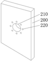
Optionally, a first circular groove is formed in the center of the standard plate, and a plurality of first through holes are formed in the standard plate around the center of the first circular groove.
Optionally, a second circular groove is formed in the center of the mounting plate, and a plurality of second through holes are formed in the mounting plate around the center of the second circular groove.
Optionally, the roughness of the fitting surface of the positioning rod is ra6.4, and the cylindricity of the positioning rod is less than 0.01 mm.
The beneficial effect that this application can realize is as follows:
the method separates the tests of a vision measuring subsystem and a pose measuring subsystem carried by a flange end of a complex integrated industrial robot, evaluates the performance of each subsystem in sequence, utilizes an auxiliary tool calibration plate and a standard plate, firstly, the industrial robot moves the standard plate to respectively test whether different polygonal grooves on the calibration plate can be accurately aligned or not to verify the accuracy of the vision measuring subsystem of the industrial robot, then, after the position of the standard plate is changed by adjusting the pose of the industrial robot, the method tests whether different side edges of the standard plate can be accurately aligned to different strip-shaped grooves on the calibration plate or not, and the angle of the standard plate needs to be rotated for many times in the alignment process, thereby verifying the accuracy of the angle adjustment of the pose adjusting subsystem of the industrial robot, the steps designed by the method can be verified repeatedly, and the verification requirements of the industrial robots with different system comprehensive positioning accuracy levels can be realized by adjusting the matching degree of the calibration plate and the standard plate, by adding the calibration plate and the standard plate auxiliary tool, the state of a machined surface does not need to be considered, the verification conclusion is jointly determined based on the verification result and the machining size of the standard part, the data is accurate, the conclusion is reliable, the operation is simple, and the test cost is lower.
Drawings
In order to more clearly illustrate the detailed description of the present application or the technical solutions in the prior art, the drawings that are needed in the detailed description of the present application or the technical solutions in the prior art will be briefly described below. Throughout the drawings, like elements or portions are generally identified by like reference numerals. In the drawings, elements or portions are not necessarily drawn to scale.
Fig. 1 is a schematic flow chart of a comprehensive positioning accuracy testing method for an industrial robot integrated system in an embodiment of the application;
FIG. 2 is a schematic diagram of a calibration plate according to an embodiment of the present application;
FIG. 3 is a schematic structural diagram of a standard plate in an embodiment of the present application;
fig. 4 is a schematic structural diagram of a standard rod in an embodiment of the present application.
Reference numerals:
100-calibration plate, 110-polygonal groove, 120-strip-shaped groove, 130-positioning hole, 200-standard plate, 210-first circular groove, 220-first through hole, 300-standard rod, 310-mounting plate, 311-second circular groove, 312-second through hole and 320-positioning rod.
The implementation, functional features and advantages of the objectives of the present application will be further explained with reference to the accompanying drawings.
Detailed Description
The technical solutions in the embodiments of the present application will be described clearly and completely with reference to the drawings in the embodiments of the present application, and it is obvious that the described embodiments are only a part of the embodiments of the present application, and not all of the embodiments. All other embodiments, which can be derived by a person skilled in the art from the embodiments given herein without making any creative effort, shall fall within the protection scope of the present application.
It should be noted that all the directional indications (such as up, down, left, right, front, and back … …) in the embodiment of the present application are only used to explain the relative position relationship between the components, the motion situation, and the like in a specific posture, and if the specific posture is changed, the directional indication is changed accordingly.
In this application, unless expressly stated or limited otherwise, the terms "connected," "secured," and the like are to be construed broadly, and for example, "secured" may be a fixed connection, a removable connection, or an integral part; can be mechanically or electrically connected; they may be directly connected or indirectly connected through intervening media, or they may be connected internally or in any other suitable relationship, unless expressly stated otherwise. The specific meaning of the above terms in the present application can be understood by those of ordinary skill in the art as appropriate.
In addition, if there is a description of "first", "second", etc. in the embodiments of the present application, the description of "first", "second", etc. is for descriptive purposes only and is not to be construed as indicating or implying relative importance or implicitly indicating the number of technical features indicated. Thus, a feature defined as "first" or "second" may explicitly or implicitly include at least one such feature. In addition, the meaning of "and/or" appearing throughout includes three juxtapositions, exemplified by "A and/or B" including either A or B or both A and B. In addition, technical solutions between various embodiments may be combined with each other, but must be realized by a person skilled in the art, and when the technical solutions are contradictory or cannot be realized, such a combination should not be considered to exist, and is not within the protection scope of the present application.
Examples
Referring to fig. 1 to 4, the embodiment provides a comprehensive positioning accuracy testing method for an integrated system of an industrial robot, comprising the following steps:
placing a calibration plate 100 on a plane with the flatness not lower than 0.05 mm/m; wherein, a plurality of polygonal grooves 110 and a plurality of strip-shaped grooves 120 are formed on the calibration plate 100;
determining a reference point of each of the polygonal grooves 110;
installing a standard plate 200 at the flange end of the industrial robot; the shape of the standard plate 200 is the same as that of the polygonal groove 110, and the side end of the standard plate 200 is used for being abutted to the strip-shaped groove 120;
moving the standard plate 200 to the datum point by operating the industrial robot, enabling the front surface of the standard plate 200 to be sequentially aligned with the corresponding polygonal grooves 110, and if the standard plate 200 can be aligned with the polygonal grooves, judging that the vision measuring subsystem of the industrial robot passes detection;
adjusting the position and the posture of the industrial robot to enable the standard board 200 to be perpendicular to the calibration board 100;
and operating the industrial robot to move the standard plate 200, so that different sides of the standard plate 200 are sequentially in butt joint with the corresponding strip-shaped grooves 120, and if the standard plate and the strip-shaped grooves are in butt joint, judging that the pose adjusting subsystem of the industrial robot passes detection.
In this embodiment, the test of the vision measuring subsystem and the pose measuring subsystem carried by the flange end of the complex integrated industrial robot is separated, the performance of each subsystem is evaluated in sequence, the auxiliary tool calibration plate 100 and the standard plate 200 are used to complete the test together, the calibration plate 100 with a plurality of polygonal grooves 110 and a plurality of strip-shaped grooves 120 is fixed on the horizontal plane, then the industrial robot moves the standard plate 200 to test whether the calibration plate can be accurately aligned with different polygonal grooves 110 on the calibration plate 100 to verify the accuracy of the vision measuring subsystem of the industrial robot, then after the position of the standard plate 200 is changed by adjusting the pose of the industrial robot, whether different sides of the standard plate 200 can be accurately aligned with different strip-shaped grooves 120 on the calibration plate 100 is tested, the angle of the standard plate 200 needs to be rotated for a plurality of times in the alignment process, so as to verify the accuracy of the angle adjustment of the pose adjusting subsystem of the industrial robot, the steps designed by the application can be repeatedly verified, the verification requirements of the industrial robots with different system comprehensive positioning precision levels can be met by adjusting the matching degree of the calibration plate 100 and the standard plate 200, the machining face state does not need to be considered by adding auxiliary tools of the calibration plate 100 and the standard plate 200, the verification conclusion is jointly determined based on the verification result and the machining size of the standard part, the data is accurate, the conclusion is reliable, the operation is simple, and the test cost is lower.
As an optional implementation manner, the calibration plate 100 further has a plurality of positioning holes 130, and the hole center lines of the plurality of positioning holes 130 are not parallel to each other;
the method comprises the following steps that the operating industrial robot moves the standard plate 200, the side end of the standard plate 200 is sequentially matched with the corresponding strip-shaped groove 120, if the standard plate is matched with the strip-shaped groove, the visual measurement subsystem of the operating industrial robot is judged to pass through the detection step, and the method further comprises the following steps:
removing the standard plate 200 from the industrial robot flange end;
installing a standard rod 300 at the flange end of the industrial robot; the standard rod 300 comprises a mounting plate 310 connected with a flange end of the industrial robot, the mounting plate 310 is connected with a positioning rod 320, and the positioning rod 320 is used for matching with the positioning hole 130;
and operating the industrial robot to move the standard rod 300, so that the positioning rods 320 are sequentially aligned with the corresponding positioning holes 130, and if the alignment is successful, judging that the vision measuring subsystem and the pose adjusting subsystem of the industrial robot both pass the detection.
In this embodiment, after the test of the matching between the standard board 200 and the calibration board 100, the standard board 200 is replaced with the standard rod 300 with greater difficulty in matching, and during the matching, the positioning rod 320 needs to be matched into the positioning hole 130, so as to comprehensively verify the comprehensive positioning accuracy of the system of the industrial robot through a smaller area of the identification region and a more accurate pose inclination angle, and because the hole center lines of each positioning hole 130 are not parallel to each other, i.e. the opening direction of some positioning holes 130 is inclined relative to the calibration board 100, the industrial robot moves the standard rod 300 to match the positioning rod 320 into the corresponding positioning hole 130, not only the position of the positioning hole 130 needs to be visually scanned, but also the inclination angle position of the positioning rod 320 needs to be adjusted, so as to accurately match the positioning rod 320 into the corresponding positioning hole 130, and after the matching is successful, it can be verified that both the vision measuring subsystem and the pose adjusting subsystem of the industrial robot pass the detection, the accuracy and reliability of the detection data are further improved by improving the detection difficulty and comprehensively detecting the vision measuring subsystem and the pose adjusting subsystem.
It should be noted that, taking a six-axis industrial robot as an example, after all the above steps are completed, changing the angle of the 1-axis of the industrial robot, placing the calibration plate 100 in the base mark interval where the end flange is located when the 1-axis of the robot is at 0 °, -90 °, +90 °, and repeating the above steps, and if the 1-axis of the robot is located at 0 °, -90 °, +90 ° when the polygonal grooves 110 of the calibration plate 200 and the calibration plate 100 can be aligned in sequence, and the standard rod 300 and the positioning hole 130 of the calibration plate 100 can be aligned in sequence, it is considered that the system comprehensive positioning accuracy of the industrial robot passes the detection, and the system comprehensive positioning accuracy detection of the six-axis industrial robot is realized.
As an optional implementation, the determining the reference point of each polygonal slot 110 includes:
determining four positioning points on the calibration plate 100;
starting a vision measurement subsystem of the industrial robot to find four positioning points of the calibration plate 100, and taking the plane where the four positioning points are located as a reference plane;
operating the vision measurement subsystem of the industrial robot to scan all of the polygonal slots 110;
the diagonals of the polygonal groove 110 are connected to obtain an intersection point, and the intersection point is used as a reference point of the reference plane.
In this embodiment, when determining the reference points of the polygonal slot 110, the visual measurement subsystem of the industrial robot may find out four positioning points of the calibration plate 100, so as to determine the reference plane first, and then when the visual measurement subsystem scans all the polygonal slots 110, the most basic task of "leveling plane" is completed, an object coordinate system is defined, and with the diagonal intersection point of the polygonal slot 110 as the reference point, the plane is determined first, and then the plane is determined, so as to improve the accuracy of finding points, and the finally determined reference point can be used as a motion reference coordinate point input to the industrial robot.
As an alternative embodiment, when the diagonals of the polygonal groove 110 are connected to have a plurality of intersection points that do not overlap with each other, the method for determining the reference point includes:
recording all the intersection points;
connecting the intersection points to form a graph and making diagonal lines;
and iterating the steps of connecting the intersection points to form a graph and making diagonal lines until the length of the diagonal lines is reduced to be less than 1% or 0.3mm of the length of the first connecting line, and determining the area in the intersection points of the diagonal lines at the moment as the reference point of the reference surface.
In the present embodiment, since there may be a case where the polygonal groove 110 has an irregular polygonal shape and the number of polygonal bars is 5 or more, there may be a case where there are a plurality of diagonal lines connecting the intersection points, at this time, the intersection points are connected to form a graph and a diagonal line is made, and the step is iterated until the length of the diagonal line is reduced to 1% or less than 0.3mm of the length of the first connection line, and finally, the region in the intersection point of the diagonal line is determined as a reference point of the reference plane, which may also be used as a reference coordinate point for the industrial robot to find the polygonal groove 110.
As an optional implementation, the determining four positioning points on the calibration board 100 includes:
round marks are respectively arranged at four corners of the calibration plate 100; wherein the circular mark is a circle with a radius of 1-3mm, the color of the circular mark is different from that of the calibration plate 100, and the circular mark is tangent to two adjacent edges of the calibration plate 100;
and taking the area of the circular area where the circular mark is positioned as an anchor point.
In the present embodiment, circular marks having different colors from the color of the calibration board 100 are set at four corners of the calibration board 100 as the location points of the area, so that the reference plane determined by the four location points can substantially cover the calibration board 100, and the circular marks have color identification degrees relative to the calibration board 100, so as to be conveniently scanned, and the circular marks are also used for positioning action planes, thereby preventing errors caused by parallelism or uneven processing.
Here, the circular mark may be pasted by a circular sticker with a radius of 2mm, or may be formed by directly applying a color paint on the calibration board 100.
As an alternative embodiment, the polygonal groove 110 is in a regular polygon or an irregular polygon, where an irregular polygon is preferred, and the polygonal groove 110 with an irregular polygon can increase the detection difficulty, thereby increasing the accuracy of the detection data.
As an alternative embodiment, the relative positions of the polygonal grooves 110 are different from each other, and the relative positions of the strip-shaped grooves 120 are different from each other, for example, the polygonal grooves 110 are configured as irregular quadrilateral grooves, at least one quadrilateral groove is configured relatively vertically, one quadrilateral groove is configured relatively horizontally, one quadrilateral groove is configured obliquely, and two strip-shaped grooves 120 can be configured and are respectively perpendicular to each other, so that the difficulty of finding the position of the industrial robot during the matching process is increased, and the detection accuracy is improved.
As an alternative embodiment, the positioning hole 130 includes at least one vertical circular hole and at least two inclined circular holes, a hole center line of the vertical circular hole is perpendicular to the calibration plate 100, a hole center line of the inclined circular hole and the calibration plate 100 have an inclined included angle, the inclined included angle ranges from 20 ° to 60 °, and the inclined included angles of different inclined circular holes are different from each other.
In this embodiment, utilize perpendicular round hole and slope round hole to test industrial robot respectively and drive the degree of accuracy that positioning rod 320 was looked for and is closing, improve and close the degree of difficulty, further improve and detect accuracy and reliability, the slope contained angle of slope round hole here can select for use one 20, a 45 tests.
As an optional implementation manner, the maximum gap between the edges of the standard board 200 and the calibration board 100 after being aligned is not more than 0.3mm, the maximum gap between the corners is not more than 1mm, the roughness of the alignment surfaces of the calibration board 100 and the standard board 200 is ra6.4, and the flatness of the alignment surfaces of the calibration board 100 and the standard board 200 is less than 0.05 mm/m.
As an alternative embodiment, the standard board 200 has a first circular groove 210 formed at the center thereof, and the standard board 200 has a plurality of first through holes 220 formed around the center of the first circular groove 210. The first circular groove 210 is provided with a groove depth of 5mm, a groove radius of 20mm, and the number of the first through holes 220 is 8, so that the flange plates of industrial robots of all models can be adapted by adjusting the diameter of a circular construction line and the center distance of a circular array.
As an alternative embodiment, the mounting plate 310 has a second circular groove 311 formed at the center thereof, and the mounting plate 310 has a plurality of second through holes 312 formed around the center of the second circular groove 311, and the number of the second through holes 312 is 6. The second circular groove 311 is provided with a groove depth of 5mm and a groove radius of 20mm, and can be adapted to all types of industrial robot flange plates by adjusting the diameter of a circular construction line and the center distance of a circular array
As an alternative embodiment, the roughness of the mating surface of the positioning rod 320 is ra6.4, and the cylindricity of the positioning rod 320 is less than 0.01 mm.
The above description is only a preferred embodiment of the present application, and not intended to limit the scope of the present application, and all modifications of equivalent structures and equivalent processes, which are made by the contents of the specification and the drawings of the present application, or which are directly or indirectly applied to other related technical fields, are included in the scope of the present application.
Claims (10)
1. A comprehensive positioning precision testing method for an industrial robot integrated system is characterized by comprising the following steps:
placing a calibration plate on a plane with the flatness not lower than 0.05 mm/m; the calibration plate is provided with a plurality of polygonal grooves and a plurality of strip-shaped grooves;
determining a reference point of each polygonal groove;
installing a standard plate at the flange end of the industrial robot; the shape of the standard plate is the same as that of the polygonal groove, and the side end of the standard plate is used for being butted with the strip-shaped groove;
the operating industrial robot moves the standard plate to approach the datum point, so that the front surface of the standard plate is sequentially matched with the corresponding polygonal grooves, and if the standard plate and the polygonal grooves are matched, the visual measurement subsystem of the industrial robot is judged to pass detection;
adjusting the position and the posture of the industrial robot to enable the standard plate to be perpendicular to the calibration plate;
operating the industrial robot to move the standard plate to enable different side edges of the standard plate to be sequentially aligned with the corresponding strip-shaped grooves, and judging that the pose adjusting subsystem of the industrial robot passes detection if the standard plate and the strip-shaped grooves can be aligned;
the determining the reference point of each polygonal groove comprises:
determining four positioning points on the calibration plate;
starting a vision measurement subsystem of the industrial robot to find four positioning points of the calibration plate, and taking the plane where the four positioning points are located as a reference plane;
operating a vision measurement subsystem of the industrial robot to scan all the polygonal grooves;
connecting the diagonals of the polygonal grooves to obtain an intersection point, and taking the intersection point as a reference point of the reference plane;
when the diagonals of the polygonal groove are connected and have a plurality of non-coincident intersection points, the method for determining the reference point comprises the following steps:
recording all the intersection points;
connecting the intersection points to form a graph and making diagonal lines;
and iterating the steps of connecting the intersection points to form a graph and making diagonal lines until the length of the diagonal lines is reduced to be less than 1% or 0.3mm of the length of the first connecting line, and determining the area in the intersection points of the diagonal lines at the moment as the reference point of the reference surface.
2. The method for testing the comprehensive positioning accuracy of the integrated system of the industrial robot according to claim 1, wherein the calibration plate is further provided with a plurality of positioning holes, and the hole center lines of the plurality of positioning holes are not parallel to each other;
the operating industrial robot moves the standard plate to enable the side end of the standard plate to be sequentially matched with the corresponding strip-shaped groove, if the standard plate and the strip-shaped groove are matched, the operating industrial robot further comprises the following steps after the step of detecting the vision measuring subsystem of the industrial robot is judged to pass through:
removing the standard plate from the flange end of the industrial robot;
installing a standard rod at the flange end of the industrial robot; the standard rod comprises a mounting plate connected with a flange end of the industrial robot, the mounting plate is connected with a positioning rod, and the positioning rod is used for being matched with the positioning hole;
and operating the industrial robot to move the standard rods, enabling the positioning rods to be sequentially aligned with the corresponding positioning holes, and judging that the vision measuring subsystem and the pose adjusting subsystem of the industrial robot pass detection if the positioning rods can be aligned with the corresponding positioning holes.
3. The integrated positioning accuracy testing method for the industrial robot integration system according to claim 1, wherein the determining of four positioning points on the calibration plate comprises:
round marks are respectively arranged at four corners of the calibration plate; wherein the circular mark is a circle with the radius of 1-3mm, the color of the circular mark is different from that of the calibration plate, and the circular mark is tangent to two adjacent edges of the calibration plate;
and taking the area of the circular area where the circular mark is positioned as an anchor point.
4. The integrated positioning accuracy testing method for industrial robot systems according to claim 3, wherein the polygonal groove has a regular or irregular polygonal shape.
5. The integrated positioning accuracy testing method for an industrial robot system according to claim 1, wherein the relative positions of the polygonal grooves are different from each other, and the relative positions of the strip-shaped grooves are different from each other.
6. The integrated positioning accuracy testing method for the industrial robot integrated system as claimed in claim 2, wherein said positioning hole comprises at least one vertical circular hole and at least two inclined circular holes, the hole center line of said vertical circular hole is perpendicular to said calibration plate, the hole center line of said inclined circular hole and said calibration plate have an inclined included angle, and the inclined included angles of said inclined circular holes are in the range of 20 ° to 60 °, and different inclined circular holes are different from each other.
7. The method for testing the comprehensive positioning accuracy of the integrated system of the industrial robot according to claim 1, wherein the maximum gap between the edges of the standard plate and the calibration plate after the alignment is not more than 0.3mm, the maximum gap between the angles is not more than 1mm, the roughness of the alignment surfaces of the calibration plate and the standard plate is Ra6.4, and the flatness of the alignment surfaces of the calibration plate and the standard plate is less than 0.05 mm/m.
8. The integrated positioning accuracy testing method for the industrial robot integrated system as claimed in claim 1, wherein the standard plate has a first circular groove formed at a center thereof, and the standard plate has a plurality of first through holes formed around the center of the first circular groove.
9. The method for testing the comprehensive positioning accuracy of the integrated system of an industrial robot according to claim 2, wherein the mounting plate is provided with a second circular groove at the center, and the mounting plate is provided with a plurality of second through holes around the center of the second circular groove.
10. The integrated positioning accuracy testing method for the industrial robot integration system as claimed in claim 9, wherein the roughness of the butt-joint surface of the positioning rod is ra6.4, and the cylindricity of the positioning rod is less than 0.01 mm.
Priority Applications (1)
| Application Number | Priority Date | Filing Date | Title |
|---|---|---|---|
| CN202210124693.XA CN114166252B (en) | 2022-02-10 | 2022-02-10 | Comprehensive positioning precision testing method for industrial robot integrated system |
Applications Claiming Priority (1)
| Application Number | Priority Date | Filing Date | Title |
|---|---|---|---|
| CN202210124693.XA CN114166252B (en) | 2022-02-10 | 2022-02-10 | Comprehensive positioning precision testing method for industrial robot integrated system |
Publications (2)
| Publication Number | Publication Date |
|---|---|
| CN114166252A CN114166252A (en) | 2022-03-11 |
| CN114166252B true CN114166252B (en) | 2022-05-10 |
Family
ID=80489611
Family Applications (1)
| Application Number | Title | Priority Date | Filing Date |
|---|---|---|---|
| CN202210124693.XA Active CN114166252B (en) | 2022-02-10 | 2022-02-10 | Comprehensive positioning precision testing method for industrial robot integrated system |
Country Status (1)
| Country | Link |
|---|---|
| CN (1) | CN114166252B (en) |
Citations (26)
| Publication number | Priority date | Publication date | Assignee | Title |
|---|---|---|---|---|
| CN103292748A (en) * | 2013-01-05 | 2013-09-11 | 中国航空工业集团公司西安飞机设计研究所 | Multi-substrate combining detection method based on laser measurement |
| WO2014026074A2 (en) * | 2012-08-09 | 2014-02-13 | Bae Systems Information And Electronic Systems Integration Inc. | Integrated data registration |
| CN106584513A (en) * | 2017-01-26 | 2017-04-26 | 武汉延锋时代检测技术股份有限公司 | Industrial robot repeated positioning accuracy testing method and industrial robot repeated positioning accuracy testing device |
| CN107091651A (en) * | 2017-06-29 | 2017-08-25 | 飞智控(天津)科技有限公司 | Navigation module alignment aid and calibration method |
| CN107560544A (en) * | 2017-09-12 | 2018-01-09 | 上海大学 | One kind is used for robot hole positioning and normal direction measurement apparatus and method |
| CN107817005A (en) * | 2017-10-09 | 2018-03-20 | 大连理工大学 | The integrated flexible experimental method of monocular pose measurement accuracy evaluation |
| CN108286946A (en) * | 2018-01-30 | 2018-07-17 | 周蕊 | The method and system of sensing station mark fixed sum data splicing |
| CN208223395U (en) * | 2018-05-29 | 2018-12-11 | 北京零壹空间科技有限公司 | Caliberating device positioning plate and caliberating device |
| CN208305109U (en) * | 2018-04-11 | 2019-01-01 | 马鞍山思卡瑞自动化科技有限公司 | A kind of auxiliary fixing device for industrial robot |
| CN109794938A (en) * | 2019-02-01 | 2019-05-24 | 南京航空航天大学 | A kind of robot hole error-compensating apparatus and its method suitable for curved-surface structure |
| CN109916328A (en) * | 2017-12-13 | 2019-06-21 | 山东大学 | A kind of the V-shaped groove scaling board and method of double CCD laser measurements |
| WO2019152360A1 (en) * | 2018-01-30 | 2019-08-08 | Brooks Automation, Inc. | Automatic wafer centering method and apparatus |
| CN110125980A (en) * | 2019-05-21 | 2019-08-16 | 中国科学院沈阳自动化研究所 | The caliberating device and scaling method of industrial robot repetitive positioning accuracy measuring device |
| CN209459611U (en) * | 2019-03-06 | 2019-10-01 | 成都飞机工业(集团)有限责任公司 | A kind of machine table displacement sensor calibrated in situ auxiliary device |
| CN110503885A (en) * | 2019-09-18 | 2019-11-26 | 江苏汇博机器人技术股份有限公司 | A kind of combined industrial robot application expertise real training evaluating platform |
| CN209840961U (en) * | 2019-06-26 | 2019-12-24 | 房山 | Automatic boundary detection cutting equipment for plates |
| CN111069740A (en) * | 2019-12-24 | 2020-04-28 | 哈尔滨焊接研究院有限公司 | Flexible control method and system for robot welding process |
| CN111307033A (en) * | 2018-12-12 | 2020-06-19 | 成都蒸汽巨人机器人科技有限公司 | Industrial robot depth vision sensor calibration board and calibration method |
| CN111571088A (en) * | 2020-05-11 | 2020-08-25 | 海盐县法兰厂 | High-strength welding neck flange and processing method thereof |
| CN112066879A (en) * | 2020-09-11 | 2020-12-11 | 哈尔滨工业大学 | Air floatation motion simulator pose measuring device and method based on computer vision |
| CN112629499A (en) * | 2020-12-03 | 2021-04-09 | 合肥富煌君达高科信息技术有限公司 | Hand-eye calibration repeated positioning precision measuring method and device based on line scanner |
| CN112917510A (en) * | 2019-12-06 | 2021-06-08 | 中国科学院沈阳自动化研究所 | Industrial robot space position appearance precision test system |
| CN214352551U (en) * | 2020-12-25 | 2021-10-08 | 东莞市李群自动化技术有限公司 | Movable platform and robot tail end load mounting device |
| CN214470919U (en) * | 2021-01-14 | 2021-10-22 | 广东中准检测有限公司 | High-precision calibrator for optical measuring instrument |
| CN113681590A (en) * | 2021-08-27 | 2021-11-23 | 中国矿业大学 | Modular robot docking device and docking method |
| CN113781301A (en) * | 2021-08-25 | 2021-12-10 | 深圳群宾精密工业有限公司 | 3D visual point cloud data splicing method, system and storage medium |
Family Cites Families (10)
| Publication number | Priority date | Publication date | Assignee | Title |
|---|---|---|---|---|
| CN101372079A (en) * | 2008-09-26 | 2009-02-25 | 浙江大学 | Industrial robot cutting and processing system applied to auxiliary assembly of airplane as well as method |
| WO2010085536A2 (en) * | 2009-01-23 | 2010-07-29 | Acro Associates | Fluid control platform, fluid control systems, intelligent fluid control components and optical aperture sensors |
| US9958854B2 (en) * | 2013-06-10 | 2018-05-01 | The Boeing Company | Systems and methods for robotic measurement of parts |
| US9511496B2 (en) * | 2014-06-20 | 2016-12-06 | The Boeing Company | Robot alignment systems and methods of aligning a robot |
| CN105716525B (en) * | 2016-03-30 | 2018-03-30 | 西北工业大学 | End effector of robot coordinate system scaling method based on laser tracker |
| CN205664842U (en) * | 2016-06-06 | 2016-10-26 | 陕西铁路工程职业技术学院 | Calibration fine -adjustment device for surveying and mapping instrument |
| CN207215014U (en) * | 2017-05-12 | 2018-04-10 | 上海电器科学研究所(集团)有限公司 | A kind of industrial robot measures end target ball fast-positioning device |
| CN111721270A (en) * | 2019-03-21 | 2020-09-29 | 深圳市道通科技股份有限公司 | Two-line laser |
| CN111660295B (en) * | 2020-05-28 | 2023-01-03 | 中国科学院宁波材料技术与工程研究所 | Industrial robot absolute precision calibration system and calibration method |
| CN215217497U (en) * | 2021-06-16 | 2021-12-17 | 阳光学院 | Calibration device for underwater measurement of stereoscopic vision equipment |
-
2022
- 2022-02-10 CN CN202210124693.XA patent/CN114166252B/en active Active
Patent Citations (26)
| Publication number | Priority date | Publication date | Assignee | Title |
|---|---|---|---|---|
| WO2014026074A2 (en) * | 2012-08-09 | 2014-02-13 | Bae Systems Information And Electronic Systems Integration Inc. | Integrated data registration |
| CN103292748A (en) * | 2013-01-05 | 2013-09-11 | 中国航空工业集团公司西安飞机设计研究所 | Multi-substrate combining detection method based on laser measurement |
| CN106584513A (en) * | 2017-01-26 | 2017-04-26 | 武汉延锋时代检测技术股份有限公司 | Industrial robot repeated positioning accuracy testing method and industrial robot repeated positioning accuracy testing device |
| CN107091651A (en) * | 2017-06-29 | 2017-08-25 | 飞智控(天津)科技有限公司 | Navigation module alignment aid and calibration method |
| CN107560544A (en) * | 2017-09-12 | 2018-01-09 | 上海大学 | One kind is used for robot hole positioning and normal direction measurement apparatus and method |
| CN107817005A (en) * | 2017-10-09 | 2018-03-20 | 大连理工大学 | The integrated flexible experimental method of monocular pose measurement accuracy evaluation |
| CN109916328A (en) * | 2017-12-13 | 2019-06-21 | 山东大学 | A kind of the V-shaped groove scaling board and method of double CCD laser measurements |
| CN108286946A (en) * | 2018-01-30 | 2018-07-17 | 周蕊 | The method and system of sensing station mark fixed sum data splicing |
| WO2019152360A1 (en) * | 2018-01-30 | 2019-08-08 | Brooks Automation, Inc. | Automatic wafer centering method and apparatus |
| CN208305109U (en) * | 2018-04-11 | 2019-01-01 | 马鞍山思卡瑞自动化科技有限公司 | A kind of auxiliary fixing device for industrial robot |
| CN208223395U (en) * | 2018-05-29 | 2018-12-11 | 北京零壹空间科技有限公司 | Caliberating device positioning plate and caliberating device |
| CN111307033A (en) * | 2018-12-12 | 2020-06-19 | 成都蒸汽巨人机器人科技有限公司 | Industrial robot depth vision sensor calibration board and calibration method |
| CN109794938A (en) * | 2019-02-01 | 2019-05-24 | 南京航空航天大学 | A kind of robot hole error-compensating apparatus and its method suitable for curved-surface structure |
| CN209459611U (en) * | 2019-03-06 | 2019-10-01 | 成都飞机工业(集团)有限责任公司 | A kind of machine table displacement sensor calibrated in situ auxiliary device |
| CN110125980A (en) * | 2019-05-21 | 2019-08-16 | 中国科学院沈阳自动化研究所 | The caliberating device and scaling method of industrial robot repetitive positioning accuracy measuring device |
| CN209840961U (en) * | 2019-06-26 | 2019-12-24 | 房山 | Automatic boundary detection cutting equipment for plates |
| CN110503885A (en) * | 2019-09-18 | 2019-11-26 | 江苏汇博机器人技术股份有限公司 | A kind of combined industrial robot application expertise real training evaluating platform |
| CN112917510A (en) * | 2019-12-06 | 2021-06-08 | 中国科学院沈阳自动化研究所 | Industrial robot space position appearance precision test system |
| CN111069740A (en) * | 2019-12-24 | 2020-04-28 | 哈尔滨焊接研究院有限公司 | Flexible control method and system for robot welding process |
| CN111571088A (en) * | 2020-05-11 | 2020-08-25 | 海盐县法兰厂 | High-strength welding neck flange and processing method thereof |
| CN112066879A (en) * | 2020-09-11 | 2020-12-11 | 哈尔滨工业大学 | Air floatation motion simulator pose measuring device and method based on computer vision |
| CN112629499A (en) * | 2020-12-03 | 2021-04-09 | 合肥富煌君达高科信息技术有限公司 | Hand-eye calibration repeated positioning precision measuring method and device based on line scanner |
| CN214352551U (en) * | 2020-12-25 | 2021-10-08 | 东莞市李群自动化技术有限公司 | Movable platform and robot tail end load mounting device |
| CN214470919U (en) * | 2021-01-14 | 2021-10-22 | 广东中准检测有限公司 | High-precision calibrator for optical measuring instrument |
| CN113781301A (en) * | 2021-08-25 | 2021-12-10 | 深圳群宾精密工业有限公司 | 3D visual point cloud data splicing method, system and storage medium |
| CN113681590A (en) * | 2021-08-27 | 2021-11-23 | 中国矿业大学 | Modular robot docking device and docking method |
Also Published As
| Publication number | Publication date |
|---|---|
| CN114166252A (en) | 2022-03-11 |
Similar Documents
| Publication | Publication Date | Title |
|---|---|---|
| US6154279A (en) | Method and apparatus for determining shapes of countersunk holes | |
| US11642747B2 (en) | Aligning parts using multi-part scanning and feature based coordinate systems | |
| US8111907B2 (en) | Method for repeatable optical determination of object geometry dimensions and deviations | |
| US8526705B2 (en) | Driven scanning alignment for complex shapes | |
| CN111795644B (en) | Positive intersection point laser double-measuring head pose calibration test piece | |
| CN110940267A (en) | Measuring method and measuring system thereof | |
| CN114166252B (en) | Comprehensive positioning precision testing method for industrial robot integrated system | |
| US20240077431A1 (en) | Z-axis measurement fixture and method of determining the planarity of objects using the fixture | |
| CN112595281B (en) | Method and medium for rapidly measuring surface profile of workpiece | |
| US6182494B1 (en) | Method for adjustment of transducer position to compensate for ultrasonic testing beam alignment errors | |
| JP4324159B2 (en) | Optical element measuring method and jig | |
| US11820006B2 (en) | Apparatus and method for calibrating laser displacement sensor for use with robot | |
| US11255652B2 (en) | Methods and apparatus for determining a height of an edge portion of a product | |
| CN113414248A (en) | Method and device for detecting workpiece forming process | |
| WO2020105218A1 (en) | Measurement method | |
| JP6900261B2 (en) | Processing equipment, substrate inspection equipment, processing method and substrate inspection method | |
| CN115790399B (en) | Bullet length measuring method based on double-displacement sensor | |
| TWM591613U (en) | Floor squareness measuring instrument | |
| CN220063958U (en) | Ultrasonic phased array test block and ultrasonic phased array equipment detection system | |
| JP3917972B2 (en) | Inspection device for metal belt elements | |
| TWI730479B (en) | Floor squareness measuring instrument and measuring method thereof | |
| EP3243038B1 (en) | System and method for assessing a calibration of a multi-axis ultrasonic scanner | |
| CN116538993A (en) | Method for detecting posture of reflecting surface, reflecting surface and compact range testing system | |
| JP2006300881A (en) | Method and device for measuring object | |
| CN116123976A (en) | Method and device for detecting space angle size |
Legal Events
| Date | Code | Title | Description |
|---|---|---|---|
| PB01 | Publication | ||
| PB01 | Publication | ||
| SE01 | Entry into force of request for substantive examination | ||
| SE01 | Entry into force of request for substantive examination | ||
| GR01 | Patent grant | ||
| GR01 | Patent grant |