CN114162134B - Method, device and storage medium for predicting vehicle track on sea-crossing bridge - Google Patents
Method, device and storage medium for predicting vehicle track on sea-crossing bridge Download PDFInfo
- Publication number
- CN114162134B CN114162134B CN202210131347.4A CN202210131347A CN114162134B CN 114162134 B CN114162134 B CN 114162134B CN 202210131347 A CN202210131347 A CN 202210131347A CN 114162134 B CN114162134 B CN 114162134B
- Authority
- CN
- China
- Prior art keywords
- vehicle
- motion state
- current
- equation
- wind speed
- Prior art date
- Legal status (The legal status is an assumption and is not a legal conclusion. Google has not performed a legal analysis and makes no representation as to the accuracy of the status listed.)
- Active
Links
Images


Classifications
-
- B—PERFORMING OPERATIONS; TRANSPORTING
- B60—VEHICLES IN GENERAL
- B60W—CONJOINT CONTROL OF VEHICLE SUB-UNITS OF DIFFERENT TYPE OR DIFFERENT FUNCTION; CONTROL SYSTEMS SPECIALLY ADAPTED FOR HYBRID VEHICLES; ROAD VEHICLE DRIVE CONTROL SYSTEMS FOR PURPOSES NOT RELATED TO THE CONTROL OF A PARTICULAR SUB-UNIT
- B60W50/00—Details of control systems for road vehicle drive control not related to the control of a particular sub-unit, e.g. process diagnostic or vehicle driver interfaces
- B60W50/0097—Predicting future conditions
-
- B—PERFORMING OPERATIONS; TRANSPORTING
- B60—VEHICLES IN GENERAL
- B60W—CONJOINT CONTROL OF VEHICLE SUB-UNITS OF DIFFERENT TYPE OR DIFFERENT FUNCTION; CONTROL SYSTEMS SPECIALLY ADAPTED FOR HYBRID VEHICLES; ROAD VEHICLE DRIVE CONTROL SYSTEMS FOR PURPOSES NOT RELATED TO THE CONTROL OF A PARTICULAR SUB-UNIT
- B60W40/00—Estimation or calculation of non-directly measurable driving parameters for road vehicle drive control systems not related to the control of a particular sub unit, e.g. by using mathematical models
- B60W40/10—Estimation or calculation of non-directly measurable driving parameters for road vehicle drive control systems not related to the control of a particular sub unit, e.g. by using mathematical models related to vehicle motion
- B60W40/103—Side slip angle of vehicle body
-
- B—PERFORMING OPERATIONS; TRANSPORTING
- B60—VEHICLES IN GENERAL
- B60W—CONJOINT CONTROL OF VEHICLE SUB-UNITS OF DIFFERENT TYPE OR DIFFERENT FUNCTION; CONTROL SYSTEMS SPECIALLY ADAPTED FOR HYBRID VEHICLES; ROAD VEHICLE DRIVE CONTROL SYSTEMS FOR PURPOSES NOT RELATED TO THE CONTROL OF A PARTICULAR SUB-UNIT
- B60W40/00—Estimation or calculation of non-directly measurable driving parameters for road vehicle drive control systems not related to the control of a particular sub unit, e.g. by using mathematical models
- B60W40/10—Estimation or calculation of non-directly measurable driving parameters for road vehicle drive control systems not related to the control of a particular sub unit, e.g. by using mathematical models related to vehicle motion
- B60W40/105—Speed
-
- B—PERFORMING OPERATIONS; TRANSPORTING
- B60—VEHICLES IN GENERAL
- B60W—CONJOINT CONTROL OF VEHICLE SUB-UNITS OF DIFFERENT TYPE OR DIFFERENT FUNCTION; CONTROL SYSTEMS SPECIALLY ADAPTED FOR HYBRID VEHICLES; ROAD VEHICLE DRIVE CONTROL SYSTEMS FOR PURPOSES NOT RELATED TO THE CONTROL OF A PARTICULAR SUB-UNIT
- B60W40/00—Estimation or calculation of non-directly measurable driving parameters for road vehicle drive control systems not related to the control of a particular sub unit, e.g. by using mathematical models
- B60W40/10—Estimation or calculation of non-directly measurable driving parameters for road vehicle drive control systems not related to the control of a particular sub unit, e.g. by using mathematical models related to vehicle motion
- B60W40/107—Longitudinal acceleration
-
- B—PERFORMING OPERATIONS; TRANSPORTING
- B60—VEHICLES IN GENERAL
- B60W—CONJOINT CONTROL OF VEHICLE SUB-UNITS OF DIFFERENT TYPE OR DIFFERENT FUNCTION; CONTROL SYSTEMS SPECIALLY ADAPTED FOR HYBRID VEHICLES; ROAD VEHICLE DRIVE CONTROL SYSTEMS FOR PURPOSES NOT RELATED TO THE CONTROL OF A PARTICULAR SUB-UNIT
- B60W50/00—Details of control systems for road vehicle drive control not related to the control of a particular sub-unit, e.g. process diagnostic or vehicle driver interfaces
- B60W50/0098—Details of control systems ensuring comfort, safety or stability not otherwise provided for
-
- B—PERFORMING OPERATIONS; TRANSPORTING
- B60—VEHICLES IN GENERAL
- B60W—CONJOINT CONTROL OF VEHICLE SUB-UNITS OF DIFFERENT TYPE OR DIFFERENT FUNCTION; CONTROL SYSTEMS SPECIALLY ADAPTED FOR HYBRID VEHICLES; ROAD VEHICLE DRIVE CONTROL SYSTEMS FOR PURPOSES NOT RELATED TO THE CONTROL OF A PARTICULAR SUB-UNIT
- B60W50/00—Details of control systems for road vehicle drive control not related to the control of a particular sub-unit, e.g. process diagnostic or vehicle driver interfaces
- B60W2050/0001—Details of the control system
- B60W2050/0043—Signal treatments, identification of variables or parameters, parameter estimation or state estimation
- B60W2050/0052—Filtering, filters
-
- B—PERFORMING OPERATIONS; TRANSPORTING
- B60—VEHICLES IN GENERAL
- B60W—CONJOINT CONTROL OF VEHICLE SUB-UNITS OF DIFFERENT TYPE OR DIFFERENT FUNCTION; CONTROL SYSTEMS SPECIALLY ADAPTED FOR HYBRID VEHICLES; ROAD VEHICLE DRIVE CONTROL SYSTEMS FOR PURPOSES NOT RELATED TO THE CONTROL OF A PARTICULAR SUB-UNIT
- B60W2520/00—Input parameters relating to overall vehicle dynamics
- B60W2520/06—Direction of travel
-
- B—PERFORMING OPERATIONS; TRANSPORTING
- B60—VEHICLES IN GENERAL
- B60W—CONJOINT CONTROL OF VEHICLE SUB-UNITS OF DIFFERENT TYPE OR DIFFERENT FUNCTION; CONTROL SYSTEMS SPECIALLY ADAPTED FOR HYBRID VEHICLES; ROAD VEHICLE DRIVE CONTROL SYSTEMS FOR PURPOSES NOT RELATED TO THE CONTROL OF A PARTICULAR SUB-UNIT
- B60W2520/00—Input parameters relating to overall vehicle dynamics
- B60W2520/10—Longitudinal speed
- B60W2520/105—Longitudinal acceleration
-
- B—PERFORMING OPERATIONS; TRANSPORTING
- B60—VEHICLES IN GENERAL
- B60W—CONJOINT CONTROL OF VEHICLE SUB-UNITS OF DIFFERENT TYPE OR DIFFERENT FUNCTION; CONTROL SYSTEMS SPECIALLY ADAPTED FOR HYBRID VEHICLES; ROAD VEHICLE DRIVE CONTROL SYSTEMS FOR PURPOSES NOT RELATED TO THE CONTROL OF A PARTICULAR SUB-UNIT
- B60W2520/00—Input parameters relating to overall vehicle dynamics
- B60W2520/20—Sideslip angle
-
- B—PERFORMING OPERATIONS; TRANSPORTING
- B60—VEHICLES IN GENERAL
- B60W—CONJOINT CONTROL OF VEHICLE SUB-UNITS OF DIFFERENT TYPE OR DIFFERENT FUNCTION; CONTROL SYSTEMS SPECIALLY ADAPTED FOR HYBRID VEHICLES; ROAD VEHICLE DRIVE CONTROL SYSTEMS FOR PURPOSES NOT RELATED TO THE CONTROL OF A PARTICULAR SUB-UNIT
- B60W2555/00—Input parameters relating to exterior conditions, not covered by groups B60W2552/00, B60W2554/00
- B60W2555/20—Ambient conditions, e.g. wind or rain
Landscapes
- Engineering & Computer Science (AREA)
- Automation & Control Theory (AREA)
- Transportation (AREA)
- Mechanical Engineering (AREA)
- Physics & Mathematics (AREA)
- Mathematical Physics (AREA)
- Human Computer Interaction (AREA)
- Control Of Driving Devices And Active Controlling Of Vehicle (AREA)
Abstract
The embodiment of the invention discloses a method, equipment and a storage medium for predicting a vehicle track on a cross-sea bridge. The method comprises the following steps: constructing a dynamic equation of the vehicle running on the sea-crossing bridge; wherein the kinetic equation describes a relationship between lateral wind speed and vehicle motion state; according to a Kalman filtering principle, determining a current motion state after filtering according to an actual motion state of the vehicle at the last moment and a current observation motion state, wherein the observation motion state refers to a vehicle motion state observed by observation equipment; correcting the current filtered motion state according to the current lateral wind speed by using the kinetic equation to obtain the current actual motion state; and taking the current moment as the previous moment, and returning to the Kalman filtering step until a complete vehicle track is obtained. The embodiment makes the track prediction result more practical.
Description
Technical Field
The invention relates to the technical field of bridge safety, in particular to a method, equipment and a storage medium for predicting a vehicle track on a sea-crossing bridge.
Background
The cross-sea bridge is an important traffic line in the east coastal region, and vehicles running on the cross-sea bridge are tracked and monitored, so that better traffic management is facilitated. For example, dangerous chemical transport vehicles are tracked and monitored, so that accidents are avoided, and severe consequences such as casualties, bridge structure damage and environmental pollution are avoided.
Vehicle trajectory prediction is a common means of vehicle tracking monitoring. The method comprises the steps of firstly finding out a target vehicle through vehicle identification, then tracking the position and the motion state of the vehicle in real time, and predicting the position and the state of the next moment according to the current position and the current state. The existing vehicle track prediction technology is mostly developed around a common driving environment, the perception of the surrounding environment is limited to the traffic environment such as the road surface condition, the road congestion degree and the like, and the special environmental factors on the sea-crossing bridge are difficult to be considered.
Disclosure of Invention
The invention provides a method, equipment and a storage medium for predicting a vehicle track on a cross-sea bridge, which are used for correcting the motion state of a vehicle according to environmental factors of the cross-sea bridge, so that the track prediction is more practical.
In a first aspect, the present invention provides a method for predicting a vehicle trajectory on a sea bridge, comprising:
constructing a dynamic equation of the vehicle running on the sea-crossing bridge; wherein the kinetic equation describes a relationship between lateral wind speed and vehicle motion state;
according to a Kalman filtering principle, determining a current motion state after filtering according to an actual motion state of the vehicle at the last moment and a current observation motion state, wherein the observation motion state refers to a vehicle motion state observed by observation equipment;
correcting the current motion state after filtering according to the current lateral wind speed by using the kinetic equation to obtain the current actual motion state;
and taking the current moment as the previous moment, and returning to the step of determining the current motion state after filtering according to the Kalman filtering principle and the actual motion state and the current observation motion state of the vehicle at the previous moment until a complete vehicle track is obtained.
In a second aspect, the present invention also provides an electronic device, including:
one or more processors;
a memory for storing one or more programs,
when executed by the one or more processors, cause the one or more processors to implement a method for vehicle trajectory prediction on a sea-crossing bridge as described herein.
In a third aspect, the present invention further provides a computer-readable storage medium, on which a computer program is stored, which when executed by a processor, implements the method for predicting a vehicle trajectory on a sea-crossing bridge according to the present application.
According to the method, a special environment of a sea-crossing bridge is considered, after Kalman filtering is carried out on the motion state of the vehicle, the motion state after filtering is corrected through the lateral wind speed, so that the final current actual motion state is constrained by the lateral wind speed, the actual motion state at the last moment and the current observed motion state, the actual situation is closer to the real situation, and the vehicle track is more accurate; in addition, a dynamic equation related to the lateral wind speed is constructed, a method for calculating the influence of the lateral wind speed on the motion state is provided, and the realizability of considering the lateral wind speed in the track prediction is provided.
Drawings
In order to more clearly illustrate the embodiments of the present invention or the technical solutions in the prior art, the drawings used in the description of the embodiments or the prior art will be briefly described below, and it is obvious that the drawings in the following description are some embodiments of the present invention, and other drawings can be obtained by those skilled in the art without creative efforts.
FIG. 1 is a flow chart of a method for predicting a vehicle trajectory on a cross-sea bridge according to an embodiment of the present invention;
FIG. 2 is a schematic diagram of a vehicle stress situation and a motion state provided by an embodiment of the invention;
FIG. 3 is a schematic diagram of determining a vehicle position based on binocular vision principles provided by an embodiment of the present invention;
FIG. 4 is a flowchart of another method for predicting vehicle trajectories on a cross-sea bridge according to an embodiment of the present invention;
fig. 5 is a schematic diagram of a test object grouping manner provided in an embodiment of the present application;
fig. 6 is a schematic structural diagram of an electronic device according to an embodiment of the present invention.
Detailed Description
In order to make the objects, technical solutions and advantages of the present invention more apparent, the technical solutions of the present invention will be clearly and completely described below. It is to be understood that the described embodiments are merely exemplary of the invention, and not restrictive of the full scope of the invention. All other embodiments, which can be derived by a person skilled in the art from the embodiments given herein without making any creative effort, shall fall within the protection scope of the present invention.
In the description of the present invention, it should be noted that the terms "center", "upper", "lower", "left", "right", "vertical", "horizontal", "inner", "outer", etc., indicate orientations or positional relationships based on the orientations or positional relationships shown in the drawings, and are only for convenience of description and simplicity of description, but do not indicate or imply that the device or element being referred to must have a particular orientation, be constructed and operated in a particular orientation, and thus, should not be construed as limiting the present invention. Furthermore, the terms "first," "second," and "third" are used for descriptive purposes only and are not to be construed as indicating or implying relative importance.
In the description of the present invention, it should also be noted that, unless otherwise explicitly specified or limited, the terms "mounted," "connected," and "connected" are to be construed broadly, e.g., as meaning either a fixed connection, a removable connection, or an integral connection; can be mechanically or electrically connected; they may be connected directly or indirectly through intervening media, or they may be interconnected between two elements. The specific meanings of the above terms in the present invention can be understood in specific cases to those skilled in the art.
Fig. 1 is a flowchart of a method for predicting a vehicle trajectory on a sea-crossing bridge according to an embodiment of the present invention, which is suitable for tracking and monitoring a traveling vehicle on the sea-crossing bridge, and the embodiment is executed by an electronic device. With reference to fig. 1, the method provided in this embodiment specifically includes:
and S10, constructing a dynamic equation of the vehicle on the bridge, wherein the dynamic equation describes the relationship between the lateral wind speed and the motion state of the vehicle.
Lateral refers to a direction perpendicular to the direction of travel of the vehicle. The lateral wind speed refers to a wind speed perpendicular to a vehicle traveling direction. Because the wind speed on the sea-crossing bridge is very high and changeable, and the influence of the lateral wind speed on the vehicle running is obvious, the dynamic equation of the vehicle on the sea-crossing bridge is constructed by fully considering the particularity of the sea-crossing bridge environment. The dynamic equation is used for describing the relation between the lateral wind speed and the motion state of the vehicle, so that the motion state of the vehicle is corrected according to the lateral wind speed.
The motion state in the present embodiment includes position, velocity, and acceleration. Fig. 2 is a schematic diagram of a vehicle stress situation and a motion state provided by the embodiment of the invention. As shown in fig. 2, optionally, the kinetic equation is as follows:

wherein the content of the first and second substances,F i tire with indicationiSubjected to rolling friction force: (i=1、2、3、4),H i Tire with indicationiThe friction force of the side slip is applied to the bearing,T i which is indicative of the tractive effort of the vehicle,V i representing the contact force between the vehicle and the road surface;Mwhich is indicative of the mass of the vehicle, represents the vehicle running acceleration (i.e. the acceleration in the running direction),
 expressed as vehicle side-slip acceleration (i.e. acceleration in the lateral direction),grepresents the acceleration of gravity;prepresenting half of the lateral spacing of the wheels,qrepresenting the distance of the vehicle's center of mass from the road surface,randsrespectively representing the horizontal distances of the center of mass of the vehicle from the rear axle and the front axle of the vehicle;S、D、Lrespectively represents the aerodynamic lateral force, the aerodynamic resistance and the aerodynamic lift force caused by the lateral wind speed,P、R、Yrespectively representing the pitch moment, roll moment and yaw moment induced by the lateral wind velocity,S、D、LandP、R、Ycan be obtained by the lateral wind speed. It can be seen that equation (1) describes the lateral wind speed and the vehicle travel acceleration
 And side-slip acceleration
 The relationship (c) can be used as a kinetic equation in the present embodiment.
And S20, according to a Kalman filtering principle, determining the current motion state after filtering according to the actual motion state of the vehicle at the last moment and the current observed motion state of the vehicle, wherein the observed motion state refers to the motion state of the vehicle observed by the road side equipment.
The basic principle of Kalman filtering is; firstly, according to a set prediction equation, predicting the current motion state by the motion state at the previous moment; meanwhile, observing the current motion state through observation equipment; and then, optimizing the predicted current motion state according to the observed motion state to obtain the filtered current motion state.
For the sake of convenience of distinction and description, the predicted motion state will be referred to as "predicted motion state", the observed motion state will be referred to as "observed motion state", and the filtered motion state will be referred to as "filtered motion state". In addition, the motion state in the present embodiment includes a position, a velocity, and an acceleration, and taking the observation motion state as an example, the observation motion state includes an observation position, an observation velocity, and an observation acceleration. The rest motion states are similar and are not described in detail.
Alternatively, a kinematic equation shown below is employed as the prediction equation:

wherein the content of the first and second substances,xdenotes the position, ΔxDenotes the displacement, Δ The increase in the speed is shown to be,
 the speed is indicated in the form of a speed,
 representing acceleration, ΔtRepresenting the movement time. Firstly, according to the kinematic equation, from the topPredicting the actual motion state at a moment to obtain the current predicted motion state; and then correcting the current predicted motion state according to the current observed motion state to obtain the current motion state after filtering.
It should be noted that the kinematic equation here is different from the kinematic equation obtained in S10. Kinematic equations are established based on kinematic principles describing the relationship between various kinematic state variables of the vehicle (e.g., position, velocity, and acceleration), while kinematic equations are established based on mechanical principles describing the relationship between vehicle forces and vehicle motion.
And S30, correcting the current motion state after filtering according to the current lateral wind speed by using the kinetic equation to obtain the current actual motion state.
Because the kinematic equation describes the relationship among the motion state variables of the vehicle, and it is difficult to reflect the influence of the external factor of the lateral wind speed on the motion state of the vehicle, the motion state after filtering is considered as not a real motion state in the present embodiment, and is to be further corrected, and the corrected motion state is referred to as an "actual motion state".
The influence of the lateral wind speed on the motion state of the vehicle is reflected through a kinetic equation, so that the motion state after filtering is corrected. Taking the dynamic equation (1) as an example, the lateral wind speed and the vehicle running acceleration are described And side-slip acceleration
 At least the current filtered travel acceleration or the current filtered side-slip acceleration of the vehicle can be corrected to obtain a current actual travel acceleration or a current actual side-slip acceleration. For the unmodified motion variable, the current filtered value is taken as the current actual value.
And S40, taking the current moment as the previous moment, and returning to the step of determining the current motion state after filtering according to the Kalman filtering principle and the actual motion state and the current observation motion state of the vehicle at the previous moment until a complete vehicle track is obtained.
Steps S20 and S30 are a continuously repeated process: and after the current actual motion state is obtained from the actual motion state at the last moment through S20 and S30, continuously returning to S20 and S30 to obtain the actual motion state at the next moment from the current actual motion state, and repeating the cycle until the actual motion states at all moments are obtained, namely the complete vehicle track is obtained.
The technical effect of the embodiment is as follows: the special environment of the sea-crossing bridge is considered, after Kalman filtering is carried out on the motion state of the vehicle, the motion state after filtering is corrected through the lateral wind speed, so that the final current actual motion state is constrained by the lateral wind speed, the actual motion state at the last moment and the current observed motion state together, the actual situation is closer to the real situation, and the vehicle track is more accurate; in addition, the embodiment constructs a dynamic equation related to the lateral wind speed, provides a calculation method for the influence of the lateral wind speed on the motion state, and provides realizability for considering the lateral wind speed in the track prediction.
On the basis of the above embodiment and the following embodiment, the present embodiment refines the construction process of the kinetic equation. Optionally, the method for constructing the dynamic equation of the vehicle running on the sea-crossing bridge comprises the following steps:
and S11, constructing a basic equation of the vehicle on the bridge based on the stress balance and moment balance principles.
The force balance and moment balance are basic principles for constructing a dynamic equation, so that a basic equation of a vehicle is constructed according to the force balance and moment balance in the driving direction, the lateral direction and the vertical direction. Alternatively, the equation set (1) is adopted as the basic equation of the present embodiment. The first three equations are established according to the stress balance principle of the driving direction, the lateral direction and the vertical direction, and the last three equations are established according to the moment balance principle of the driving direction, the lateral direction and the vertical direction.
In order to further reduce the number of unknown variables in the basic equation, the present embodiment optimizes the basic equation to be used as the final kinetic equation.
And S12, determining the motion state related variable and the lateral wind speed related variable in the basic equation.
The purpose of constructing the kinetic equation is to describe the relationship between the lateral wind speed and the vehicle motion state. Therefore, the variables related to the motion state and the variables related to the lateral wind speed are firstly determined from the basic equation so as to further clarify the relationship between the two.
Wherein the motion state related variables include: acceleration of travel And side-slip acceleration
 (ii) a The lateral wind speed related variables include: pneumatic side forceSPneumatic resistanceDAnd aerodynamic lift forceLAnd pitching momentPRolling momentRAnd yaw momentY。
And S13, determining a motion relation equation between the motion state related variable and the motion state.
The motion state comprises: position, velocity, and acceleration. Wherein the position includes a driving direction position and a side-slip position, the velocity includes a driving velocity (velocity in the driving direction) and a side-slip velocity (velocity in the side-slip direction), and the acceleration includes a driving acceleration and a side-slip acceleration. The motion state related variable in the present embodiment is the running acceleration And side-slip acceleration
 They are themselves part of the motion state.
And S14, determining a wind speed relation equation between the lateral wind speed related variable and the lateral wind speed.
The lateral wind speed related variables are: pneumatic side forceSPneumatic resistanceDAnd aerodynamic lift forceLAnd pitching momentPRolling momentRDeviation from harmonyMoment of rotationY. The wind speed relationship between them and the lateral wind speed is as follows:

wherein the content of the first and second substances,ρwhich represents the density of the air,Uthe lateral wind speed is indicated and,Athe area of the vehicle facing the wind is represented,C D 、C S 、C L 、C R 、C P 、C Y is known as the aerodynamic coefficient.
And S15, determining variable relation equations among the rest variables.
The remaining variables refer to the variables in the underlying equation (1) other than the state of motion related variable and the lateral wind speed related variable. And the variable relation equation among other variables is determined, so that the number of unknown variables in the equation can be further reduced, and the solvability of the equation is enhanced. The remaining variables in this embodiment include: rolling friction forceF i Side-slip friction forceH i Traction forceT i Contact force of the contact memberV i (ii) a The variable relation equations between the remaining variables are:

wherein, the first and the second end of the pipe are connected with each other,nindicating that the known rolling friction coefficient is known,mindicating the known coefficient of side-slip friction,krepresenting dimensionless coefficients.
It should be noted that the other parameters in the basic equation: vehicle massMRepresents the acceleration of gravitygHalf of the lateral distance of the wheelpDistance of vehicle center of mass from road surfaceqAnd the horizontal distance of the vehicle's center of mass from the rear and front axles of the vehiclerAndscan be directly obtained in a simple manner, and is considered as a fixed quantity in the present embodiment.
And S16, combining the basic equation, the motion relation equation, the wind speed relation equation and the variable relation equation to obtain a dynamic equation.
In this embodiment, the equation sets (1), (3) and (4) are combined to obtain the final kinetic equation. Through the dynamic equation, the driving acceleration and the sideslip acceleration can be solved according to the lateral wind speed, and the motion state can be corrected.
The implementation starts from the influence mechanism of lateral wind speed on the vehicle, and a basic equation of a dynamic equation is constructed through stress balance and moment balance; then searching a motion state related variable and a lateral wind speed related variable from the basic equation, and extending the basic equation to the motion state and the lateral wind speed so as to establish clear connection between the motion state related variable and the lateral wind speed related variable; and finally, the number of unknown variables is reduced by determining the relation between other variables, and the solvability of the equation set is improved. The dynamic equations formed in a simultaneous mode can reflect the relation between the motion state and the lateral wind speed, the number of unknown variables is reduced to a controllable range, and the solvability is high.
On the basis of the above-described embodiment and the following embodiments, the present embodiment refines the loop process of S20, S30, and S40. Optionally, the vehicle is a hazardous chemical substance vehicle, and the observation device is two roadside cameras.
Serious adverse effects can be generated when a safety accident occurs to the dangerous chemical vehicle, so that higher precision is required for tracking the track of the dangerous chemical vehicle. The existing vehicle identification technology generally observes the position information of a vehicle in real time through a vehicle-mounted GPS, due to the limitation of long distance in the air for passing of satellites, the data error of GPS positioning is about 5m generally, the width of a bridge deck of a three-lane is about 12m generally, and 5m exceeds the error acceptable range of a sea-crossing bridge. Therefore, the significance of adopting GPS data to track vehicles and predict tracks for monitoring dangerous chemical vehicles by a sea-crossing bridge management department is not great. The embodiment directly adopts the road side camera to observe the motion state of the vehicle, and has higher observation precision compared with an on-vehicle GPS.
In the above application scenario, the loop process of S20, S30 and S40 can be roughly divided into the following four stages:
and (I) according to a Kalman filtering principle, determining the current motion state after filtering according to the actual motion state of the vehicle at the last moment and the current observation motion state. The method specifically comprises the following steps:
and S21, extracting a current image shot by each camera according to the system time of the two road side cameras, wherein the current image records the position of the vehicle at the current time.
In order to improve the observation accuracy, the present embodiment will use two roadside cameras to simulate a binocular camera, and determine the current observation position of the vehicle based on the principle of binocular vision. The common binocular camera in the market comprises two cameras, the two cameras are controlled by the same processing chip, and the system time is completely synchronous, so that the images shot at the same system time record the position of the vehicle at the same actual moment, and the binocular vision principle can be directly adopted for positioning calculation. However, the two roadside cameras in this embodiment are independent of each other, the system time is not completely synchronized, and the images shot at the same actual time need to be extracted for positioning calculation.
Alternatively, the time when the electronic device executes step S20 is taken as the current time. Each time step S20 is executed, images recorded of the vehicle position at the present time captured by the two roadside cameras are first extracted. In practical application, the system time of the electronic device and the roadside camera is not completely consistent.
For the above reasons, the present embodiment first performs timestamp correction according to the system time of the electronic device and the system time of each camera when extracting the current image of each camera, and ensures that the position of the vehicle at the current time is recorded in the extracted image.
In a specific embodiment, one of the electronic equipment and the two roadside cameras is used as main equipment, and the rest equipment is used as slave equipment; the master device sends master device system time to the slave devices according to preset time intervals, and each slave device proofreads the time stamp of interactive data (images or control signals and the like) according to the master device system time to ensure the time synchronization of the interactive data.
And S22, determining the current observed motion state of the vehicle based on the binocular vision principle according to the positions of the vehicle in the two current images.
Specifically, fig. 3 is a schematic diagram of positioning based on binocular vision principle provided by an embodiment of the present invention. As shown in fig. 3, point P represents the vehicle,O cL 、O cR the optical centers of the two road side cameras are respectively. Setting the left camera coordinate systemO cL - x cL y cL z cL Is located at the origin of the world coordinate system and does not rotate; image coordinate system of left cameraO L -X L Y L Effective focal length off L . Coordinate system of right side cameraO cR -x cR y cR z cR Image coordinate system of the right cameraO R -X R Y R Effective focal length off R . The positional relationship between the coordinate systems of the left and right cameras is expressed by a spatial transformation matrix as:

where [ R | T ] is a spatial transformation matrix, R is a rotation matrix, and T is a translation matrix.
In this step, first, the image coordinates of the vehicle in the two current images are acquired: (X L ,Y L ) And (a)X R ,Y R ) Then, the real coordinates of the vehicle are calculated by the following formula (x,y,z) I.e. the position of the vehicle on the sea-crossing bridge:

optionally, before extracting the current image captured by each camera according to the system time difference between the two roadside cameras, the method further includes: and calibrating the heights of the optical centers of the two road side cameras to make the heights of the optical centers consistent.
In the binocular vision positioning algorithm in the above embodiment, the optical center heights of the left and right cameras are consistent by default. In practical applications, the optical center heights of the two roadside cameras may not be consistent, and the optical center heights of the roadside cameras are calibrated first before the current image is extracted.
In one embodiment, first, an image captured by the roadside camera is randomly acquired, which is used to calibrate the optical center, referred to as a calibration image; then, according to the camera imaging principle, the original optical center height of the camera is identified from the calibration image; and if the heights are inconsistent, sending out an optical center calibration warning for prompting maintenance personnel to adjust the mounting heights of the two drive test cameras so as to keep the optical center height. And after adjustment, randomly acquiring the calibration image again until the optical center heights are consistent.
The embodiment realizes vehicle positioning based on the binocular vision principle, and improves positioning accuracy. However, the existing binocular camera is expensive in manufacturing cost and limited in shooting distance, and is mainly used for laboratory research. The embodiment makes full use of the existing equipment, and two roadside cameras are adopted to replace binocular cameras, so that the shooting distance is greatly increased; and through time calibration and optical center calibration, a binocular vision positioning algorithm is optimized, the problems that the time of two road side cameras is asynchronous and the optical centers are not coaxial are solved, and the applicability of the algorithm in a cross-sea bridge vehicle identification scene is improved. In addition, the existing road side equipment is only needed to be utilized, an observation sensor does not need to be additionally installed on the vehicle, the number of equipment is reduced, and the maintenance and the utilization are convenient; meanwhile, information interaction between roadside equipment and the vehicle and between the vehicle and the vehicle is not needed, and other noises caused by a complex interaction process are avoided.
Optionally, the image coordinates of the vehicle in the two current images are acquired (ii)X L ,Y L ) And (a)X R ,Y R ) Before, still include: obtaining the typical vehicles of the road section continuously shot by each cameraAn image set (such as a typical hazardous chemical vehicle) comprising images of vehicles with different angles and different degrees of obstruction; and (3) labeling the vehicles in the image by adopting a picture labeling tool labelImg, and training a typical vehicle recognition model by utilizing a YOLO algorithm.
Accordingly, the image coordinates of the vehicle in the two current images are acquired: (X L ,Y L ) And (a)X R ,Y R ) The method comprises the following steps: and recognizing the current image by using the trained typical vehicle recognition model to obtain the image coordinates of the vehicle in the current image.
The embodiment combines the YOLO algorithm and the improved binocular vision algorithm to realize identification and positioning of the dangerous chemical vehicle, and compared with the traditional positioning method, the positioning accuracy is higher.
And (II) after the observation motion state is obtained by using the YOLO and binocular vision principle, Kalman filtering is performed by using the observation motion state. This embodiment will be describednThe moment is taken as the current moment, and the current actual motion state of the vehicle is defined as The actual position, the actual speed and the actual acceleration in the direction of travel and in the lateral direction are respectively referred to as: an actual travel position, an actual travel speed, an actual travel acceleration, an actual lateral position, an actual side-slip velocity, and an actual side-slip acceleration.
Optionally, according to the kalman filtering principle, determining the current filtered motion state from the last-time actual motion state and the current observed motion state of the vehicle includes the following steps:
and S23, predicting the current motion state according to the actual motion state at the previous moment according to the following formula:
X n n ,-1 =FX n-1(7)
wherein the content of the first and second substances,X n n,-1indicating the current state of the predictive system,X n-1is shown onThe actual state of motion at a moment in time,Frepresenting a state transition matrix. Optionally, deriving from the prediction equation (2)FThe specific expression of (a) is as follows:

wherein the content of the first and second substances,∆trepresenting the time interval between the current time and the last time. This equation is invariant throughout the kalman filtering process.
And S24, calculating the current prediction error matrix of the motion state according to the following formula by the state transition matrix:
P n,n -1=FP n n-1,-1F T +Q(9)
wherein the content of the first and second substances,P n,n-1which represents the current prediction error matrix and,P n n-1,-1the prediction error matrix for the last moment is represented,Qrepresenting the process noise matrix. Assuming that the direction of travel and the lateral direction are uncorrelated,Qcalculated as follows:

wherein the content of the first and second substances, represents the variance of the acceleration and represents the calculation accuracy of the calculation formula, which will be described in the present embodiment
 Considered as a known quantity.
S25, calculating the current Kalman gain according to the following formula by the current prediction error matrix:
Kn = P n,n -1 H T (HP n,n-1 H T +Rn)-1 (11)
wherein the content of the first and second substances,Kn representing a current kalman gain;Rnrepresenting the observation error, determined by the parameters of the observation equipment (i.e. the two roadside cameras), considered in this embodiment to be known fixed values; h represents an observation matrix, and satisfies an observation equation:z n =HXnwherein, in the step (A),z n identifying a current viewing position, including a current driving position, for a binocular vision algorithmx n,measured And current lateral positiony n,measured ,z n = [x n,measured y n,measured ]T, 。
。
S26, according to the following formula, optimizing the current prediction motion state by the current Kalman gain and the current observation motion state to obtain the current motion state after filtering:
X n n ,= X n n,-1 +K n (z n -HX n,n-1)(12)
wherein the content of the first and second substances,X n n,representing the current post-filter motion state.
S27, calculating the prediction error matrix of the next moment according to the following formula:
P n n ,=(1- K n H)P n n,-1(1- K n H ) T + K n R n K n T (13)
the present embodiment does not incorporate complex acceleration defining equations and kinetic equations into the state transition matrixFIn the method, the simplest state transition matrix is adopted to calculate the Kalman gain, and the filtered motion is obtained according to the observed motion state and the predicted motion stateA state; and then correcting the filtered driving acceleration according to the definition of the acceleration, and correcting the filtered lateral acceleration by using a kinetic equation so as to obtain the actual motion state. By the mode, the influence of lateral wind speed on the motion state is fully considered, and the construction of a huge matrix form is avoidedFAndF Tthe computational complexity of equations (9) - (13) is simplified.
After the current motion state after filtering is obtained, the current motion state after filtering is corrected by using the kinetic equation to obtain the current actual motion state, and the method specifically comprises the following steps:
and S31, obtaining the current actual driving acceleration according to the current filtered position, the actual position at the last moment and the actual position at the last moment.
As can be seen from equation (8), the current predicted acceleration is the same as the actual acceleration at the previous time. In the calculation process of equations (9) - (13), the acceleration is always unchanged, i.e., the current filtered acceleration is still equal to the actual acceleration at the last moment, which does not match the actual acceleration. Therefore, the present embodiment assumes that the current time, the previous time, and the previous time move along a straight line, and then calculates a new current acceleration as the current actual travel acceleration, based on the definition of the acceleration, using the current filtered position obtained by the kalman filter, and the already determined actual position at the previous time and the actual position at the previous time.
And S32, judging whether the pneumatic lateral force of the vehicle exceeds a set threshold value according to the lateral wind speed and the kinetic equation.
The function of the kinetic equation is to correct the motion state after filtering according to the lateral wind speed. When the lateral stress is small, the lateral stress is balanced, and the lateral wind speed does not influence the motion state; only when the aerodynamic lateral force reaches a certain degree will the lateral wind speed have an influence on the state of motion.
The second equation in the set of equations (1) is determined as the lateral stress balance equation of the vehicle according to the kinetic equation, and the set threshold value is determined according to the lateral stress balance equation,H 1 + H 2 + H 3 + H 4 + S = 0, can yield = &S| =|H 1 + H 2 + H 3 + H 4|<m|V 1 + V 2 + V 3 + V 4|<m|MgL. Therefore, the present embodiment will be describedm|MgAnd | is used as a set threshold.
Specifically, first, the lateral wind speed is setUSubstituted into equation set (3)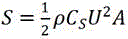 To obtain the pneumatic lateral forceS. Then, comparing-SL and thresholdm|Mg|。
And S33, if the pneumatic lateral force does not exceed the set threshold value, taking the current filtered motion state as the current actual motion state.
If notS| ≤m|MgAnd if the lateral wind speed does not influence the motion state, taking the current motion state after filtering as the current actual motion state.
And S33, if the pneumatic side force exceeds the set threshold value, calculating the current actual motion state according to the kinetic equation.
If notS| >m|MgIf the lateral wind speed is considered to influence the motion state, the current filtered driving acceleration is used And lateral wind velocityUAnd (4) substituting the current actual motion state into the simultaneous power equations of (1), (3) and (4). Specifically, substituting equations (3) and (4) into equation (1) results in 6 equations, including 6 unknown variables: contact forceV i (i=1, 2, 3, 4), side-slip acceleration
 And dimensionless coefficientk. In the subsequent embodiment, 6 equations and 6 variables exist in the equation set, and can beA set of unique solutions is solved. Side slip acceleration obtained by solving
 I.e., the current actual side-slip acceleration.
In the present embodiment, the objects of the lateral wind speed-to-motional state correction are the running acceleration and the side-slip acceleration, and the actual values of the remaining motional state variables are kept unchanged after filtering. In the embodiment, the pneumatic side force threshold value is set, if the wind speed is very low and the pneumatic side force is smaller than the threshold value, the current actual side slip acceleration does not need to be calculated according to a dynamic equation, and the calculation amount is reduced.
And (IV) after the current actual motion state is obtained, taking the current moment as the previous moment, taking the current actual motion state as the previous moment actual motion state, and returning to the step S20 until a complete vehicle track is obtained.
Fig. 4 is a flowchart of another method for predicting a vehicle trajectory on a sea bridge according to an embodiment of the present invention, which shows the above loop processes of S20, S30, and S40.
On the basis of the above-described embodiment and the following embodiments, the present embodiment optimizes the kinetic equations. Optionally, constructing a basic equation of the vehicle on the bridge based on the principle of force balance and moment balance includes:
step one, constructing a vehicle steering wheel corner model according to driver information.
In view of the strict requirement of the hazardous chemical substance vehicle trajectory prediction on the accuracy, the embodiment considers the special natural environment on the sea-crossing bridge and also considers the influence of the driver information on the vehicle motion state. The driver information includes: driver age, driver driving age, and driver abnormal behavior data on the current road segment. These driver information all affect the steering wheel angle of the vehicle, thereby interfering with the vehicle's motion. Therefore, a steering wheel angle model is first constructed to describe the influence of the driver information on the steering wheel angle.
And secondly, constructing a basic equation of the vehicle on the bridge based on the stress balance and moment balance principles according to the steering wheel corner model.
The basic equation was constructed as follows:

wherein the content of the first and second substances,δthe steering angle of the steering wheel of the vehicle can be determined by the steering wheel angle model.
In the vehicle dynamics model of the embodiment, the driver information, the environmental factors of the sea-crossing bridge and the parameters of the hazardous chemical substance vehicles are comprehensively considered, so that the determined vehicle response accords with the driving scene, and the problem that the vehicle is in an accident due to the fact that the improper operation of the driver on the sea-crossing bridge is amplified by the adverse environmental factors is solved.
On the basis of the above-described embodiment and the following-described embodiment, the present embodiment refines the construction process of the vehicle steering wheel angle model. Optionally, constructing a vehicle steering wheel angle model according to the driver information, specifically including:
the method comprises the steps of firstly, obtaining multiple groups of original data, wherein each group of original data comprises original data of driver age, original data of driver driving age, original data of abnormal driver behaviors, original data of vehicle lateral displacement and original data of steering angles of a vehicle steering wheel.
The method for acquiring the multiple groups of original data comprises the following steps: the driver factors have random variability, taking the influence of the driver as a factor that affects the steering angle of the steering wheel of the vehicle. A driver simulation driving test is adopted, and raw data of driver age, driver driving age, typical abnormal behavior of the driver, vehicle lateral displacement and steering angle of a vehicle steering wheel are collected.
In the driving simulation test performed in this example, first, test subjects were selected according to the age and driving age of the driver. The driving age of the driver refers to the time when the driver is engaged in the transportation of dangerous chemical vehicles, and is divided into three groups of within one year, more than one year and less than five years, five years and more than five years. The driver ages are divided into three groups of 30 years old, 30-50 years old and more than 50 years old, and the national regulation that the driver ages below 60 years old for dangerous chemical transportation is met. The same number of drivers of different driving ages and age groups are selected as shown in fig. 5. The test objects are divided into a plurality of groups according to different variable types, each group of tests are repeated for a plurality of times, and a plurality of steering angle data are continuously acquired according to the lateral displacement of the output control vehicle each time. Accordingly, a plurality of groups of original data including original data of driver age, original data of driver driving age, original data of abnormal driver behavior, original data of vehicle lateral displacement and original data of steering angle of a steering wheel of the vehicle are obtained.
And assigning the original data of the abnormal behavior of the driver. The driver has no abnormal behavior assigned 0, the smoke assigned 1, the mobile phone assigned 2, and the fatigue driving assigned 3. There are many abnormal behaviors of the driver, such as drunk driving and road rage, but these behaviors are not easy to detect and are not considered in the steering wheel steering angle model.
And secondly, performing model training through a machine learning linear regression algorithm based on the multiple groups of original data to obtain the steering wheel steering angle model.
Specifically, the original data of the age of the driver, the original data of the driving age of the driver, the original data of the abnormal behavior of the driver and the original data of the lateral displacement of the vehicle in the multiple groups of original data are input into a current steering wheel steering angle model, and multiple outputs of the current steering wheel steering angle model corresponding to the multiple groups of original data are obtained; inputting a plurality of outputs of the current steering wheel steering angle model and original data of the vehicle steering wheel steering angle in a plurality of groups of original data into a loss function, and judging whether the output of the loss function meets a preset requirement or not; in response to the output of the loss function meeting a preset requirement, taking the current steering wheel steering angle model as a preset steering wheel steering angle model; and responding to the condition that the output of the loss function does not meet the preset requirement, adjusting the linear regression fitting coefficient of the current steering wheel steering angle model according to the output of the loss function, and entering the next iteration operation according to the steering wheel steering angle model after the model parameters are adjusted and multiple groups of original data until the preset steering wheel steering angle model is obtained.
Wherein the current steering wheel steering angle model isδ θ (a) =θ 0 + θ 1 a 1 + θ 2 a 2 + θ 3 a 3 + θ 4 a 4, As an output of the current steering wheel steering angle model,a 1、a 2、a 3anda 4respectively comprises the original data of the age of the driver, the original data of the driving age of the driver, the original data of the abnormal behavior of the driver and the original data of the lateral displacement of the vehicle in each group of original data,θ 0、θ 1、θ 2、θ 3andθ 4for the linear regression fit coefficient of the current steering wheel steering angle model, the loss function is
 ,
, Is as followsiThe output of the current steering wheel steering angle model corresponding to the set of raw data,δ i()is as followsiThe vehicle steering wheel steering angle raw data in the set of raw data,lthe number of sets of raw data.
Training a current steering wheel steering angle model in Matlab, and determining a parameter value which minimizes a loss function by using a gradient descent method. The number of iterations in this example is 1500 and the gradient descent step size is 0.01.
It should be noted that, the preset steering wheel steering angle model in this embodiment may be updated continuously, that is, historical data of transportation operations of hazardous chemical substance vehicles on the sea-crossing bridge may be stored to update the raw data for training the preset steering wheel steering angle model, and when the raw data for training the steering wheel steering angle model is updated, step one and step two in this embodiment may be performed to update the linear regression fitting coefficient in the steering wheel steering angle model, so as to improve the accuracy of the model.
In the embodiment, a preset steering wheel steering angle model is determined through a machine learning linear regression algorithm, and the age of a driver, the driving age of the driver, the typical abnormal behavior of the driver and the lateral displacement of the vehicle are comprehensively used as factors influencing the steering angle of the steering wheel of the vehicle, so that the steering angle of the steering wheel of the vehicle is associated with vehicle parameters and driver information, the relationship between the steering angle of the steering wheel of the vehicle and other physical quantities is reflected, and the purpose of improving the accuracy of the steering angle of the steering wheel of the vehicle is achieved.
Fig. 6 is a schematic structural diagram of an electronic device according to an embodiment of the present invention, as shown in fig. 6, the electronic device includes a processor 50, a memory 51, an input device 52, and an output device 53; the number of processors 50 in the device may be one or more, and one processor 50 is taken as an example in fig. 6; the processor 50, the memory 51, the input device 52 and the output device 53 in the apparatus may be connected by a bus or other means, as exemplified by the bus connection in fig. 6.
The memory 51 is a computer-readable storage medium for storing software programs, computer-executable programs, and modules, such as program instructions/modules corresponding to a method for predicting a vehicle trajectory on a cross-sea bridge according to an embodiment of the present invention. The processor 50 executes various functional applications and data processing of the device by running software programs, instructions and modules stored in the memory 51, so as to implement the above-mentioned method for predicting the vehicle trajectory on the sea-crossing bridge.
The memory 51 may mainly include a storage program area and a storage data area, wherein the storage program area may store an operating system, an application program required for at least one function; the storage data area may store data created according to the use of the terminal, and the like. Further, the memory 51 may include high speed random access memory, and may also include non-volatile memory, such as at least one magnetic disk storage device, flash memory device, or other non-volatile solid state storage device. In some examples, the memory 51 may further include memory located remotely from the processor 50, which may be connected to the device over a network. Examples of such networks include, but are not limited to, the internet, intranets, local area networks, mobile communication networks, and combinations thereof.
The input device 52 is operable to receive input numeric or character information and to generate key signal inputs relating to user settings and function controls of the apparatus. The output device 53 may include a display device such as a display screen.
Embodiments of the present invention further provide a computer-readable storage medium, on which a computer program is stored, where the computer program, when executed by a processor, implements a method for predicting a vehicle trajectory on a cross-sea bridge according to any of the embodiments.
Computer storage media for embodiments of the invention may employ any combination of one or more computer-readable media. The computer readable medium may be a computer readable signal medium or a computer readable storage medium. A computer readable storage medium may be, for example, but not limited to, an electronic, magnetic, optical, electromagnetic, infrared, or semiconductor system, apparatus, or device, or any combination of the foregoing. More specific examples (a non-exhaustive list) of the computer readable storage medium would include the following: an electrical connection having one or more wires, a portable computer diskette, a hard disk, a Random Access Memory (RAM), a read-only memory (ROM), an erasable programmable read-only memory (EPROM or flash memory), an optical fiber, a portable compact disc read-only memory (CD-ROM), an optical storage device, a magnetic storage device, or any suitable combination of the foregoing. In the context of this document, a computer readable storage medium may be any tangible medium that can contain, or store a program for use by or in connection with an instruction execution system, apparatus, or device.
A computer readable signal medium may include a propagated data signal with computer readable program code embodied therein, for example, in baseband or as part of a carrier wave. Such a propagated data signal may take many forms, including, but not limited to, electro-magnetic, optical, or any suitable combination thereof. A computer readable signal medium may also be any computer readable medium that is not a computer readable storage medium and that can communicate, propagate, or transport a program for use by or in connection with an instruction execution system, apparatus, or device.
Program code embodied on a computer readable medium may be transmitted using any appropriate medium, including but not limited to wireless, wireline, optical fiber cable, RF, etc., or any suitable combination of the foregoing.
Computer program code for carrying out operations for aspects of the present invention may be written in any combination of one or more programming languages, including an object oriented programming language such as Java, Smalltalk, C + +, or the like, as well as conventional procedural programming languages, such as the "C" programming language or similar programming languages. The program code may execute entirely on the user's computer, partly on the user's computer, as a stand-alone software package, partly on the user's computer and partly on a remote computer or entirely on the remote computer or server. In the case of a remote computer, the remote computer may be connected to the user's computer through any type of network, including a Local Area Network (LAN) or a Wide Area Network (WAN), or the connection may be made to an external computer (for example, through the Internet using an Internet service provider).
Finally, it should be noted that: the above embodiments are only used to illustrate the technical solution of the present invention, and not to limit the same; while the invention has been described in detail and with reference to the foregoing embodiments, it will be understood by those skilled in the art that: the technical solutions described in the foregoing embodiments may still be modified, or some or all of the technical features may be equivalently replaced; and the modifications or the substitutions do not make the essence of the corresponding technical solutions deviate from the technical solutions of the embodiments of the present invention.
Claims (9)
1. A method for predicting vehicle tracks on a cross-sea bridge is characterized by comprising the following steps:
constructing a dynamic equation of the vehicle running on the sea-crossing bridge; wherein the kinetic equation describes a relationship between lateral wind speed and vehicle motion state;
according to a Kalman filtering principle, determining a current motion state after filtering according to an actual motion state of the vehicle at the last moment and a current observation motion state, wherein the observation motion state refers to a vehicle motion state observed by observation equipment;
correcting the current motion state after filtering according to the current lateral wind speed by using the kinetic equation to obtain the current actual motion state;
taking the current moment as the previous moment, and returning to the step of determining the current motion state after filtering according to the Kalman filtering principle and the actual motion state and the current observation motion state of the vehicle at the previous moment until a complete vehicle track is obtained;
the method comprises the following steps of constructing a dynamic equation of a vehicle running on a cross-sea bridge girder, wherein the dynamic equation comprises the following steps:
constructing a basic equation of the vehicle on the bridge based on a stress balance and moment balance principle:
determining a motion state related variable and a lateral wind speed related variable in the basic equation;
determining a motion relation equation between the motion state related variable and the motion state;
determining a wind speed relation equation between the lateral wind speed related variable and the lateral wind speed:
determining the variable relation equation among the other variables:
and combining the basic equation, the motion relation equation, the wind speed relation equation and the variable relation equation to obtain the kinetic equation.
2. The method of claim 1, wherein the vehicle is a hazardous chemical vehicle and the observation device is two roadside cameras;
according to the Kalman filtering principle, determining the current motion state after filtering according to the actual motion state of the vehicle at the last moment and the current observation motion state, wherein the method comprises the following steps:
extracting a current image shot by each camera according to the system time of the two roadside cameras, wherein the current image records the position of the vehicle at the current moment;
and determining the current observed motion state of the vehicle based on a binocular vision principle according to the positions of the vehicle in the two current images.
3. The method of claim 2, wherein extracting a current image captured by each camera according to the system time of the two roadside cameras further comprises:
and calibrating the heights of the optical centers of the two road side cameras to make the heights of the optical centers consistent.
4. The method of claim 1, wherein modifying the current filtered state of motion according to a current lateral wind speed using the kinetic equation to obtain a current actual state of motion comprises:
judging whether the pneumatic lateral force of the vehicle exceeds a set threshold value or not according to the lateral wind speed, wherein the set threshold value is determined according to the kinetic equation;
if the pneumatic lateral force does not exceed the set threshold value, taking the current motion state after filtering as the current actual motion state;
and if the pneumatic side force exceeds the set threshold value, calculating the current actual motion state according to the kinetic equation.
5. The method of claim 1, wherein the motion state comprises: travel acceleration and lateral acceleration; the kinetic equation comprises: the relationship between the running acceleration and the lateral acceleration;
and correcting the current motion state after filtering according to the current lateral wind speed by using the kinetic equation to obtain the current actual motion state, wherein the method comprises the following steps:
obtaining the current actual driving acceleration according to the current filtered position, the actual position at the last moment and the actual position at the last moment;
and obtaining the current actual lateral acceleration according to the current actual running acceleration and the dynamic equation.
6. The method of claim 1, wherein constructing a fundamental equation of a vehicle on the bridge based on force balance and moment balance principles comprises:
constructing a vehicle steering wheel corner model according to the driver information;
and constructing a basic equation of the vehicle on the bridge based on a stress balance principle and a moment balance principle according to the steering wheel corner model.
7. The method of claim 6, wherein the driver information comprises: the driver age, the driver driving age and the abnormal behavior data of the driver on the current road section;
according to the driver information, constructing a vehicle steering wheel corner model, comprising:
acquiring multiple groups of original data, wherein each group of original data comprises original data of driver age, original data of driver driving age, original data of abnormal driver behavior, original data of vehicle lateral displacement and original data of steering angle of a vehicle steering wheel;
and performing model training through a machine learning linear regression algorithm based on the plurality of groups of original data to obtain the steering wheel steering angle model.
8. An electronic device, comprising:
one or more processors;
a memory for storing one or more programs,
when executed by the one or more processors, cause the one or more processors to implement the method of predicting vehicle trajectory on a transoceanic bridge of any of claims 1-7.
9. A computer-readable storage medium, on which a computer program is stored, which, when being executed by a processor, carries out a method for predicting a trajectory of a vehicle on a cross-sea bridge according to any one of claims 1 to 7.
Priority Applications (1)
| Application Number | Priority Date | Filing Date | Title |
|---|---|---|---|
| CN202210131347.4A CN114162134B (en) | 2022-02-14 | 2022-02-14 | Method, device and storage medium for predicting vehicle track on sea-crossing bridge |
Applications Claiming Priority (1)
| Application Number | Priority Date | Filing Date | Title |
|---|---|---|---|
| CN202210131347.4A CN114162134B (en) | 2022-02-14 | 2022-02-14 | Method, device and storage medium for predicting vehicle track on sea-crossing bridge |
Publications (2)
| Publication Number | Publication Date |
|---|---|
| CN114162134A CN114162134A (en) | 2022-03-11 |
| CN114162134B true CN114162134B (en) | 2022-05-06 |
Family
ID=80489930
Family Applications (1)
| Application Number | Title | Priority Date | Filing Date |
|---|---|---|---|
| CN202210131347.4A Active CN114162134B (en) | 2022-02-14 | 2022-02-14 | Method, device and storage medium for predicting vehicle track on sea-crossing bridge |
Country Status (1)
| Country | Link |
|---|---|
| CN (1) | CN114162134B (en) |
Citations (3)
| Publication number | Priority date | Publication date | Assignee | Title |
|---|---|---|---|---|
| WO2006058702A1 (en) * | 2004-12-01 | 2006-06-08 | Daimlerchrysler Ag | Device and method for stabilising a motor vehicle exposed to crosswind |
| CN204895460U (en) * | 2015-07-14 | 2015-12-23 | 内蒙古麦酷智能车技术有限公司 | Automatic adjusting device of a remotely piloted vehicle windage |
| EP3223100A1 (en) * | 2016-03-23 | 2017-09-27 | Airbus Operations GmbH | Method and system for gust speed estimation |
Family Cites Families (17)
| Publication number | Priority date | Publication date | Assignee | Title |
|---|---|---|---|---|
| JP4613668B2 (en) * | 2005-04-01 | 2011-01-19 | 日産自動車株式会社 | Vehicle behavior control apparatus and vehicle behavior control method |
| DE102006042666A1 (en) * | 2006-09-12 | 2008-03-27 | Robert Bosch Gmbh | Method for avoiding or mitigating the collision of a vehicle with at least one object |
| JP5185873B2 (en) * | 2009-03-30 | 2013-04-17 | 本田技研工業株式会社 | Vehicle skid motion state quantity estimation device |
| CN102903162B (en) * | 2012-09-24 | 2015-01-14 | 清华大学 | Automobile running state information acquisition system and method |
| CN104331611B (en) * | 2014-10-24 | 2017-07-11 | 武汉理工大学 | The dangerous situation method for early warning of road vehicle traveling and system under strong Lateral Wind |
| CN105225482B (en) * | 2015-09-02 | 2017-08-11 | 上海大学 | Vehicle detecting system and method based on binocular stereo vision |
| CN106218635B (en) * | 2016-07-22 | 2018-07-06 | 贺祥贵 | A kind of automobile rear-collision method for early warning and system |
| CN108573357B (en) * | 2018-05-08 | 2019-02-19 | 清华大学 | Driving risk real time evaluating method and its device based on equivalent force |
| JP7001009B2 (en) * | 2018-07-11 | 2022-01-19 | トヨタ自動車株式会社 | Wind data estimator |
| CN108842839B (en) * | 2018-07-25 | 2021-02-19 | 浙江工业大学 | Installation method of bridge foundation scouring monitoring equipment |
| CN109129482B (en) * | 2018-08-29 | 2021-05-25 | 武汉理工大学 | Method for dynamically compensating motion error of linear guide rail of robot |
| FR3094317B1 (en) * | 2019-04-01 | 2021-03-05 | Renault Sas | Anticipator module, real-time trajectory control device and associated process |
| EP3718847A1 (en) * | 2019-04-05 | 2020-10-07 | Continental Automotive GmbH | Method and system for tracking at least one traffic participant in a surrounding of a vehicle |
| DE102019119537A1 (en) * | 2019-07-18 | 2021-01-21 | Valeo Schalter Und Sensoren Gmbh | Method for predicting cross wind gusts acting on a carrier vehicle |
| CN110675435B (en) * | 2019-10-08 | 2022-08-02 | 上海智驾汽车科技有限公司 | Vehicle trajectory tracking method based on Kalman filtering and chi 2 detection smoothing processing |
| CN111731289B (en) * | 2020-06-24 | 2021-07-20 | 中国第一汽车股份有限公司 | Following control method and device, vehicle and storage medium |
| CN113392599B (en) * | 2021-06-18 | 2022-09-06 | 中国航空工业集团公司西安飞机设计研究所 | Method for determining dynamic response of elastic aircraft |
-
2022
- 2022-02-14 CN CN202210131347.4A patent/CN114162134B/en active Active
Patent Citations (3)
| Publication number | Priority date | Publication date | Assignee | Title |
|---|---|---|---|---|
| WO2006058702A1 (en) * | 2004-12-01 | 2006-06-08 | Daimlerchrysler Ag | Device and method for stabilising a motor vehicle exposed to crosswind |
| CN204895460U (en) * | 2015-07-14 | 2015-12-23 | 内蒙古麦酷智能车技术有限公司 | Automatic adjusting device of a remotely piloted vehicle windage |
| EP3223100A1 (en) * | 2016-03-23 | 2017-09-27 | Airbus Operations GmbH | Method and system for gust speed estimation |
Also Published As
| Publication number | Publication date |
|---|---|
| CN114162134A (en) | 2022-03-11 |
Similar Documents
| Publication | Publication Date | Title |
|---|---|---|
| CN109747659B (en) | Vehicle driving control method and device | |
| CN111272165B (en) | Intelligent vehicle positioning method based on characteristic point calibration | |
| CN112700470B (en) | Target detection and track extraction method based on traffic video stream | |
| CN108334055B (en) | Method, device and equipment for checking vehicle automatic driving algorithm and storage medium | |
| CN113168708B (en) | Lane line tracking method and device | |
| CN109084786B (en) | Map data processing method | |
| DE102019121521A1 (en) | VIDEO STABILIZATION | |
| CN111142091B (en) | Automatic driving system laser radar online calibration method fusing vehicle-mounted information | |
| CN106339692B (en) | A kind of fatigue driving state information determines method and system | |
| EP4020113A1 (en) | Dynamic model evaluation package for autonomous driving vehicles | |
| CN114758504B (en) | Online vehicle overspeed early warning method and system based on filtering correction | |
| CN108470460B (en) | Peripheral vehicle behavior identification method based on smart phone and RNN | |
| CN107600073A (en) | A kind of vehicle centroid side drift angle estimating system and method based on Multi-source Information Fusion | |
| CN113190036A (en) | Unmanned aerial vehicle flight trajectory prediction method based on LSTM neural network | |
| JP7051424B2 (en) | Anomaly detection device | |
| CN111257853B (en) | Automatic driving system laser radar online calibration method based on IMU pre-integration | |
| CN114162134B (en) | Method, device and storage medium for predicting vehicle track on sea-crossing bridge | |
| CN116985803B (en) | Self-adaptive speed control system and method for electric scooter | |
| CN117452946A (en) | Intelligent automobile remote driving method and system based on digital twin | |
| CN115826583A (en) | Automatic driving vehicle formation method based on point cloud map | |
| CN112319468B (en) | Driverless lane keeping method for maintaining road shoulder distance | |
| CN115082562A (en) | External parameter calibration method, device, equipment, server and vehicle-mounted computing equipment | |
| CN112596509A (en) | Vehicle control method, device, computer equipment and computer readable storage medium | |
| CN113870367B (en) | Method, apparatus, device, storage medium and program product for generating camera external parameters | |
| CN117330063B (en) | Method for improving accuracy of IMU and wheel speed meter combined positioning algorithm |
Legal Events
| Date | Code | Title | Description |
|---|---|---|---|
| PB01 | Publication | ||
| PB01 | Publication | ||
| SE01 | Entry into force of request for substantive examination | ||
| SE01 | Entry into force of request for substantive examination | ||
| GR01 | Patent grant | ||
| GR01 | Patent grant |