CN114007493A - Automated catheter and chest tube apparatus and related systems - Google Patents
Automated catheter and chest tube apparatus and related systems Download PDFInfo
- Publication number
- CN114007493A CN114007493A CN202080042815.XA CN202080042815A CN114007493A CN 114007493 A CN114007493 A CN 114007493A CN 202080042815 A CN202080042815 A CN 202080042815A CN 114007493 A CN114007493 A CN 114007493A
- Authority
- CN
- China
- Prior art keywords
- smart
- catheter
- chest tube
- display
- smart catheter
- Prior art date
- Legal status (The legal status is an assumption and is not a legal conclusion. Google has not performed a legal analysis and makes no representation as to the accuracy of the status listed.)
- Pending
Links
Images


Classifications
-
- A—HUMAN NECESSITIES
- A61—MEDICAL OR VETERINARY SCIENCE; HYGIENE
- A61F—FILTERS IMPLANTABLE INTO BLOOD VESSELS; PROSTHESES; DEVICES PROVIDING PATENCY TO, OR PREVENTING COLLAPSING OF, TUBULAR STRUCTURES OF THE BODY, e.g. STENTS; ORTHOPAEDIC, NURSING OR CONTRACEPTIVE DEVICES; FOMENTATION; TREATMENT OR PROTECTION OF EYES OR EARS; BANDAGES, DRESSINGS OR ABSORBENT PADS; FIRST-AID KITS
- A61F5/00—Orthopaedic methods or devices for non-surgical treatment of bones or joints; Nursing devices; Anti-rape devices
- A61F5/44—Devices worn by the patient for reception of urine, faeces, catamenial or other discharge; Portable urination aids; Colostomy devices
-
- A—HUMAN NECESSITIES
- A61—MEDICAL OR VETERINARY SCIENCE; HYGIENE
- A61B—DIAGNOSIS; SURGERY; IDENTIFICATION
- A61B5/00—Measuring for diagnostic purposes; Identification of persons
- A61B5/103—Detecting, measuring or recording devices for testing the shape, pattern, colour, size or movement of the body or parts thereof, for diagnostic purposes
- A61B5/1032—Determining colour for diagnostic purposes
-
- A—HUMAN NECESSITIES
- A61—MEDICAL OR VETERINARY SCIENCE; HYGIENE
- A61B—DIAGNOSIS; SURGERY; IDENTIFICATION
- A61B5/00—Measuring for diagnostic purposes; Identification of persons
- A61B5/20—Measuring for diagnostic purposes; Identification of persons for measuring urological functions restricted to the evaluation of the urinary system
- A61B5/207—Sensing devices adapted to collect urine
- A61B5/208—Sensing devices adapted to collect urine adapted to determine urine quantity, e.g. flow, volume
-
- A—HUMAN NECESSITIES
- A61—MEDICAL OR VETERINARY SCIENCE; HYGIENE
- A61B—DIAGNOSIS; SURGERY; IDENTIFICATION
- A61B5/00—Measuring for diagnostic purposes; Identification of persons
- A61B5/48—Other medical applications
- A61B5/4869—Determining body composition
- A61B5/4875—Hydration status, fluid retention of the body
-
- A—HUMAN NECESSITIES
- A61—MEDICAL OR VETERINARY SCIENCE; HYGIENE
- A61B—DIAGNOSIS; SURGERY; IDENTIFICATION
- A61B5/00—Measuring for diagnostic purposes; Identification of persons
- A61B5/68—Arrangements of detecting, measuring or recording means, e.g. sensors, in relation to patient
- A61B5/6846—Arrangements of detecting, measuring or recording means, e.g. sensors, in relation to patient specially adapted to be brought in contact with an internal body part, i.e. invasive
- A61B5/6847—Arrangements of detecting, measuring or recording means, e.g. sensors, in relation to patient specially adapted to be brought in contact with an internal body part, i.e. invasive mounted on an invasive device
- A61B5/6852—Catheters
-
- A—HUMAN NECESSITIES
- A61—MEDICAL OR VETERINARY SCIENCE; HYGIENE
- A61M—DEVICES FOR INTRODUCING MEDIA INTO, OR ONTO, THE BODY; DEVICES FOR TRANSDUCING BODY MEDIA OR FOR TAKING MEDIA FROM THE BODY; DEVICES FOR PRODUCING OR ENDING SLEEP OR STUPOR
- A61M25/00—Catheters; Hollow probes
- A61M25/0017—Catheters; Hollow probes specially adapted for long-term hygiene care, e.g. urethral or indwelling catheters to prevent infections
-
- A—HUMAN NECESSITIES
- A61—MEDICAL OR VETERINARY SCIENCE; HYGIENE
- A61M—DEVICES FOR INTRODUCING MEDIA INTO, OR ONTO, THE BODY; DEVICES FOR TRANSDUCING BODY MEDIA OR FOR TAKING MEDIA FROM THE BODY; DEVICES FOR PRODUCING OR ENDING SLEEP OR STUPOR
- A61M25/00—Catheters; Hollow probes
- A61M25/10—Balloon catheters
-
- A—HUMAN NECESSITIES
- A61—MEDICAL OR VETERINARY SCIENCE; HYGIENE
- A61B—DIAGNOSIS; SURGERY; IDENTIFICATION
- A61B5/00—Measuring for diagnostic purposes; Identification of persons
- A61B5/02—Detecting, measuring or recording pulse, heart rate, blood pressure or blood flow; Combined pulse/heart-rate/blood pressure determination; Evaluating a cardiovascular condition not otherwise provided for, e.g. using combinations of techniques provided for in this group with electrocardiography or electroauscultation; Heart catheters for measuring blood pressure
- A61B5/026—Measuring blood flow
-
- A—HUMAN NECESSITIES
- A61—MEDICAL OR VETERINARY SCIENCE; HYGIENE
- A61M—DEVICES FOR INTRODUCING MEDIA INTO, OR ONTO, THE BODY; DEVICES FOR TRANSDUCING BODY MEDIA OR FOR TAKING MEDIA FROM THE BODY; DEVICES FOR PRODUCING OR ENDING SLEEP OR STUPOR
- A61M27/00—Drainage appliance for wounds or the like, i.e. wound drains, implanted drains
Landscapes
- Health & Medical Sciences (AREA)
- Life Sciences & Earth Sciences (AREA)
- Heart & Thoracic Surgery (AREA)
- Engineering & Computer Science (AREA)
- Biomedical Technology (AREA)
- Animal Behavior & Ethology (AREA)
- General Health & Medical Sciences (AREA)
- Public Health (AREA)
- Veterinary Medicine (AREA)
- Biophysics (AREA)
- Molecular Biology (AREA)
- Physics & Mathematics (AREA)
- Medical Informatics (AREA)
- Pathology (AREA)
- Surgery (AREA)
- Epidemiology (AREA)
- Urology & Nephrology (AREA)
- Pulmonology (AREA)
- Hematology (AREA)
- Anesthesiology (AREA)
- Vascular Medicine (AREA)
- Orthopedic Medicine & Surgery (AREA)
- Nursing (AREA)
- Physiology (AREA)
- Child & Adolescent Psychology (AREA)
- Dentistry (AREA)
- Oral & Maxillofacial Surgery (AREA)
- External Artificial Organs (AREA)
- Media Introduction/Drainage Providing Device (AREA)
Abstract
Automated catheter and automated chest tube systems and devices. In some embodiments, the automated or intelligent catheters and chest tubes of the present disclosure include a housing for containing one or more collection containers for collecting fluids, a flexible tube for draining fluids from the bladder, chest or other suitable body part, and a measurement device that measures the amount of fluid flowing through the flexible tube and into the collection container. In some embodiments, the smart catheters and chest tubes of the present disclosure include one or more processors, one or more transmitters, and one or more receivers to send and receive data regarding the volume and other characteristics of the fluid collected in the container and to receive commands for performing various functions. An alarm is triggered when certain predetermined fluid volume thresholds are exceeded or not exceeded.
Description
Cross Reference to Related Applications
This application claims priority from U.S. provisional patent application No. 62/861,169 filed on day 13, 6, 2019 and U.S. provisional patent application No. 62/861,165 filed on day 13, 6, 2019, the entire disclosures of which are incorporated herein by reference.
Technical Field
The subject matter herein relates generally to the field of catheters, chest tubes, and related devices. The subject matter herein more particularly relates to automated catheter devices including urinary catheters and chest tubes and related systems.
Background
Modern medical catheters, especially Foley catheters, are used to collect urine from patients while they are in hospital and in medical institutions. However, the amount of urine collected by the catheter is not automatically calculated and data cannot be obtained electronically by a computer. Rather, urine output must be measured or observed manually and data plotted or recorded manually, as time permits. This can be disadvantageous to the patient because if a nurse, nursing assistant, technician, or other medical professional forgets to chart the periodic output, the provider will assume that there is no urine output. There are many potential errors including, but not limited to, spilled urine and incorrect or inaccurate measurements. This is critical to providing proper medical care. For example, if a patient is admitted for a diagnosis of diabetes insipidus, then proper recording and utilization of urine output may be a matter of life and death.
Similarly, chest tubes are used to collect air, fluids, pleural effusions, blood, chyle, or pus from a patient's chest during the patient's stay in the hospital and while in a medical facility and/or while otherwise receiving medical care. However, the amount of air, fluid, pleural effusion, blood, chyle, or pus collected by the chest tube is not automatically calculated and data cannot be obtained electronically by a computer. Instead, air or fluid output must be measured or observed manually, and data manually plotted or recorded as time permits. Similar to the catheter problem described above, if a nurse or other professional fails to record periodic air, fluid, pleural effusion, blood, chyle, or pus collected from the patient, the provider will assume no output. These types of charts are critical to receiving proper treatment, as is the case with catheters, and the potential consequences of error can be fatal. For example, if a patient is admitted to a hospital for a particular disease, proper recording and utilization of air, fluid, pleural effusion, blood, chyle, or pus output may be life-to-death.
Thus, there is a need for an automated system that delivers results in real time, or a device that collects, measures and/or records urine output and/or air, fluid, pleural effusion, blood, chyle and/or pus output with minimal or no effort on the part of the medical staff. This need is addressed by the devices and systems described herein.
Disclosure of Invention
In accordance with the present disclosure, intelligent catheters and intelligent chest tube devices and systems are provided. In one aspect, a smart catheter is provided, comprising: a flexible tube having an opening at a first end; a drainage port at an opposite second end; an inflatable balloon at the first end and proximal to the opening; a balloon port at the second end and adjacent to the drainage port; and a measurement device comprising one or more sensors integrated into or attached to the flexible tube and configured to measure an amount of fluid flowing therethrough. In some embodiments, the smart catheter is configured to drain urine from the bladder of the patient, and the measurement device is a flow meter sensor. In some embodiments, the drainage port is configured to connect or otherwise attach to one or more collection containers; and the intelligent catheter is configured to deposit urine in the one or more collection containers.
In some further embodiments, the flow meter sensor is configured to measure the amount of urine placed into the one or more collection containers. In some embodiments, the flexible tube comprises two separate channels or lumens extending along the length of the flexible tube, wherein a first lumen open at both ends connects the opening at the first end to a drainage port at the second end, wherein the second lumen connects the inflatable balloon to the balloon port. In some embodiments, the measurement device is integrated into the flexible tube at any suitable location and/or along the length of the flexible tube. In some embodiments, the measurement device includes a transmitter configured to transmit data to one or more processors in communication with the measurement device.
In some further embodiments, the transmitted data includes urine flow data; the one or more processors are configured to store and monitor urine flow data; the one or more processors are configured to monitor the amount of urine placed into the one or more collection containers of the smart catheter; and the one or more processors are configured to send a warning signal or trigger an alarm when at least one of the one or more collection containers of the smart catheter reaches one or more thresholds. In some embodiments, the one or more processors are configured to send a warning signal or trigger an alarm when the smart catheter fails. In some embodiments, components of the smart catheter are housed in a housing that includes a display screen; and a display screen configured to display a fill level of one or more collection vessels of the smart catheter.
In some embodiments, the housing further comprises a transparent or opaque door; and wherein each of the one or more collection containers is transparent or opaque. In some embodiments, one or more collection vessels include a total dissolved solids meter and/or a color sensor configured to detect and measure the color or shade of color of the fluid. In some embodiments, one or more of the collection containers include a quick connect port to connect the one or more collection containers to the smart catheter. In some embodiments, when the first collection container is removed from the smart catheter, the smart catheter is configured to automatically select the second collection container and begin draining urine into the second collection container. In some embodiments, each of the one or more collection containers includes an electrical connection configured to provide power to various components in the respective collection container and to connect the one or more processors to various components in the respective collection container.
In another aspect, a smart catheter system is provided, comprising the smart catheter of any of the above embodiments; and an external device, wherein the external device comprises a tablet computer, a mobile phone, a smart watch, an audio device, or a display device. In some embodiments, wherein the system further comprises: a power source, one or more processors, memory, receivers or transmitters, a display, an accelerometer, a speaker, and/or a tactile signal device, wherein the smart catheter, the power source, the one or more processors, memory, receivers or transmitters, the display, the accelerometer, the speaker, or the tactile signal device are interconnected with one another. In some embodiments, the display is configured to display information about the patient and/or the smart catheter.
In some embodiments, the display is configured to display identification information about the patient and information about the patient's urine; and wherein the display is configured to display information or warning or error messages regarding the capacity of each of the one or more collection containers. In some embodiments, the smart catheter system includes a computer program product comprising computer executable instructions embodied in a computer readable medium for performing steps comprising receiving electrical signals from a measurement device, processing the electrical signals to calculate data related to a measured volume, and relaying the data to an electronic display, speaker, haptic signaling device, or external device. In some embodiments, the smart catheter system is configured to measure and calculate the volume of urine or other bodily fluid produced by the patient every 30 minutes or hour, wherein the calculated volume is processed by the computer and input into the electronic chart system.
In some embodiments, the smart catheter system is configured to measure and calculate the volume of urine or other bodily fluids produced by the patient and activate an alarm when the volume of urine and/or other bodily fluids is above and/or below a predetermined threshold. In some embodiments, the smart catheter or the smart catheter system of any of the above embodiments, wherein the smart catheter or the smart catheter system is configured as a chest tube.
In another aspect, there is provided an intelligent chest tube, comprising: a flexible tube having an opening at a first end; a drainage port at an opposite second end; and a measurement device comprising one or more sensors integrated into or attached to the flexible tube and configured to measure an amount of fluid flowing therethrough. In some embodiments, the chest tube is configured to evacuate air, fluid, pleural effusion, blood, chyle, or pus from the patient's chest cavity, and wherein the measurement device is a fluid flow meter sensor. In some embodiments, the drainage port is configured to connect or otherwise attach to one or more collection containers; and the smart chest tube is configured to place air, fluid, pleural effusion, blood, chyle, or pus in the one or more collection containers. In some embodiments, the flow meter sensor is configured to measure the amount of air, fluid, pleural effusion, blood, chyle, or pus placed into the one or more collection containers.
In some further embodiments, the measurement device is integrated into the flexible tube at any suitable location and/or along the length of the flexible tube. In some embodiments, the measurement device includes a transmitter configured to transmit data to one or more processors in communication with the measurement device. In some embodiments, the transmitted data includes data regarding the flow of air, fluid, pleural effusion, blood, chyle, or pus through the flexible tube and measured by the measuring device; the one or more processors are configured to store and monitor traffic data; the one or more processors are configured to monitor the amount of air, fluid, pleural effusion, blood, chyle, or pus placed into the one or more collection containers of the smart chest tube; the one or more processors are configured to send a warning signal or trigger an alarm when at least one of the one or more collection containers of the intelligent chest tube reaches one or more thresholds.
In some further embodiments, the one or more processors are configured to send a warning signal or trigger an alarm when the intelligent chest tube fails. In some embodiments, the assembly of the smart chest tube is housed in a housing that includes a display screen; and the display screen is configured to display the filling level of the one or more collection containers of the intelligent chest tube. In some embodiments, the chest tube system is configured to measure and calculate the volume of air or bodily fluid produced by the patient and activate an alarm if the volume of air or bodily fluid is above or below one or more predetermined thresholds.
In some further embodiments, one or more of the collection vessels includes a total dissolved solids meter and/or a color sensor configured to detect and measure the color or shade of color of the fluid. In some embodiments, one or more of the collection containers include a quick connect port to connect the one or more collection containers to the smart chest tube. In some embodiments, when the first collection container is removed from the smart chest tube, the smart chest tube is configured to automatically select a second collection container and begin discharging bodily fluid into the second collection container. In some embodiments, each of the one or more collection containers includes an electrical connection configured to provide power to various components in the respective collection container and to connect the one or more processors to various components in the respective collection container.
In some embodiments, there is provided an intelligent chest tube system comprising the intelligent chest tube of any of the above claims; and an external device, wherein the external device comprises a tablet computer, a mobile phone, a smart watch, an audio device, or a display device. In some embodiments, the system further comprises: a power source, one or more processors, memory, receivers or transmitters, a display, an accelerometer, a speaker, and/or a tactile signal device, wherein the power source, one or more processors, memory, receivers or transmitters, display, accelerometer, speaker, or tactile signal device are interconnected with each other. In some embodiments, the display is configured to display information about the patient and/or the smart catheter.
In some embodiments, the display is configured to display identification information about the patient and information about the patient's urine; and
wherein the display is configured to display information or warning or error messages regarding the capacity of each of the one or more collection containers. In some embodiments, the intelligent chest tube system further comprises a computer program product comprising computer executable instructions embodied in a computer readable medium for performing steps comprising receiving an electrical signal from the measurement device, processing the electrical signal to calculate data related to the measured volume, and relaying the data to an electronic display, speaker, haptic signaling device, or external device. In some embodiments, the intelligent chest tube system is configured to measure and calculate the volume of air or body fluid produced by the patient every 30 minutes or hour, wherein the calculated volume is processed by the computer and input into the electronic charting system. In some further embodiments, the chest tube system is configured to measure and calculate the volume of air or body fluid produced by the patient and activate an alarm if the volume of air or body fluid is above and/or below a predetermined threshold.
While some aspects of the subject matter disclosed herein have been set forth above, and may be embodied in whole or in part by the subject matter disclosed, other aspects will become apparent as the description proceeds when taken in connection with the accompanying drawings, as best described below.
Drawings
The features and advantages of the present subject matter will be more readily understood from the following detailed description, which is to be read in connection with the accompanying drawings, which are given by way of illustrative and non-limiting example only, and in which:
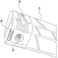
fig. 1A is a perspective view of a smart catheter device according to an embodiment of the presently disclosed subject matter;
fig. 1B is a perspective view of a smart catheter device with a display that glows in the dark according to an embodiment of the presently disclosed subject matter.
Fig. 2A depicts a front view of a smart catheter device according to an embodiment of the presently disclosed subject matter;
fig. 2B and 2C depict side views of a smart catheter device and show details of a flexible tube according to embodiments of the presently disclosed subject matter;
fig. 3A and 3B are perspective views of a smart catheter device with the door of the smart catheter half-open exposing the internal components of the smart catheter, according to an embodiment of the presently disclosed subject matter;
fig. 4A and 4B are close-up views of a vial or collection container of a smart catheter device according to embodiments of the presently disclosed subject matter;
fig. 5 is an exploded view of a vial or collection container of a smart catheter device according to an embodiment of the presently disclosed subject matter.
Fig. 6A is a perspective bottom and side view of a smart catheter device according to an embodiment of the presently disclosed subject matter.
Fig. 6B depicts a perspective rear view of a smart catheter device according to an embodiment of the presently disclosed subject matter;
fig. 7 is a close-up perspective top view of a smart catheter device according to an embodiment of the presently disclosed subject matter; and
fig. 8 is a close-up perspective view of the intelligent chest tube device and shows details of the flexible tube according to an embodiment of the presently disclosed subject matter.
Detailed Description
The present subject matter provides automated or intelligent catheter systems and devices and automated or intelligent thoracic systems and devices. In one aspect, the present subject matter provides intelligent catheter systems and devices for draining, storing, and measuring urine from a patient, and alerting or alerting healthcare personnel when the urine level reaches a particular level or the device fails. In a similar aspect, the present subject matter provides intelligent thoracic system and apparatus for draining, storing, and measuring body fluids from a patient and alerting or alerting healthcare personnel when the body fluid level reaches a particular threshold. While the following terms are believed to be well understood by those of ordinary skill in the art, the following definitions are set forth to facilitate explanation of the subject matter of the present disclosure.
Unless defined otherwise, all technical and scientific terms used herein have the same meaning as commonly understood by one of ordinary skill in the art to which the presently disclosed subject matter belongs. Although any methods, devices, and materials similar or equivalent to those described herein can be used in the practice or testing of the presently disclosed subject matter, representative methods, devices, and materials are now described.
Following long-standing patent law convention, the terms "a", "an" and "the" are used in this application, including the claims, to mean "one or more". Thus, for example, reference to "a vial" can include a plurality of such vials, and the like.
Unless otherwise indicated, all numbers expressing quantities of length, diameter, and width used in the specification and claims are to be understood as being modified in all instances by the term "about" or "approximately. Accordingly, unless indicated to the contrary, the numerical parameters set forth in the specification and attached claims are approximations that may vary depending upon the desired properties sought to be obtained by the presently disclosed subject matter.
As used herein, the terms "about" or "about" when referring to values or lengths, widths, diameters, temperatures, times, volumes, concentrations, percentages, etc., are intended to include variations from the stated amounts by ± 20%, in some embodiments ± 10%, in some embodiments ± 5%, in some embodiments ± 1%, in some embodiments ± 0.5%, and in some embodiments ± 0.1%, as such variations are suitable for the disclosed apparatus and devices.
The term "comprising" synonymous with "including", "containing" or "characterized by" is inclusive or open-ended and does not exclude additional, unrecited elements or method steps. "comprising" is a term of art used in claim language to indicate that the named element is essential, but that other elements may be added and still form a construct within the scope of the claims.
As used herein, the phrase "consisting of … …" excludes any element, step, or ingredient not specified in the claims. When the word "consisting of … …" appears in a clause in the body of a claim, rather than immediately following the preamble, it only limits the elements specified in the clause; other elements are not excluded from the claims as a whole.
As used herein, the phrase "consisting essentially of … …" limits the scope of the claims to particular materials or steps, plus those materials or steps that do not materially affect the basic and novel characteristics of the claimed subject matter.
With respect to the terms "comprising," "consisting of … …," and "consisting essentially of … …," one of these terms is used herein, the subject matter disclosed and claimed may include the use of either of the other two terms.
As used herein, the term "and/or," when used in the context of a list of entities, refers to entities that exist alone or in combination. Thus, for example, the phrase "A, B, C and/or D" includes A, B, C and D alone, but also includes any and all combinations and subcombinations of A, B, C and D.
Intelligent catheter device and system
Urinary catheters are used to collect urine from patients in hospital and in medical institutions, as well as at home and for long-term use. Urine output is collected and measured manually by nurses and other medical professionals. Unfortunately, there is no automated system that performs this important task. Rather, urine output must be measured or observed manually, and the data is typically plotted or recorded manually after hours. This is a critical step in providing proper medical care, but due to the manual nature of this task it is easily overlooked or delayed. An automated or intelligent system or device that can collect, measure and/or record urine output with minimal or no effort on the part of medical personnel would improve efficiency, accuracy, best practices, healthcare effectiveness, and successful patient recovery. The disclosed apparatus and system satisfies this unmet need. In particular, the disclosed devices and systems automatically collect, measure, calculate, and record urine output and other relevant data. In some embodiments, such catheters and catheter systems may be referred to as precision catheters, smart catheters, electronic catheters, and the like, or precision Foley, smart Foley, electronic Foley, and the like.
Referring to fig. 1A, depicted is a perspective view of one embodiment of a possible smart catheter 100 of the present disclosure attached to the side of a hospital bed. In some implementations, the smart catheter 100 may have a housing or shell that houses a subset of its components. The housing or enclosure may have a door 102, the door 102 swinging open, exposing any components therein. In some embodiments, the smart catheter 100 may also include a display 104, a flexible tube 106 (i.e., the actual catheter assembly), and an illumination element 108. Referring to fig. 1B, in some embodiments, the lighting element 108 may illuminate the room in which it is located like a night light, allowing nurses, doctors, and other medical professionals to view the display without having to turn on the lights in the room to view the contents of the catheter collection container, thereby disturbing the patient. The features of the various components are described further below.
Referring to fig. 2A, an external front view of a possible smart catheter 100 of the present disclosure is shown. In some embodiments, the door 102 includes a pattern 110, a groove, or other indicia that indicates the direction in which the door 102 is opened. This would allow a medical professional to easily determine the manner in which to open the door in an attempt to inspect or replace components within the housing of the smart catheter 100 to improve efficiency.
As shown in fig. 2B, in some embodiments, the smart catheter 100 of the present disclosure may include a clamp and/or bracket 112 at the rear of the housing that may be used to temporarily or permanently secure or attach the smart catheter 100 to a surface, such as a side of a hospital bed, a table, or other suitable location. In some embodiments, the smart catheter 100 may be configured such that the flexible tube 106 for draining urine may enter the smart catheter 100 through the top of the housing. In some embodiments, the flexible tube 106 may enter the rear of the smart catheter 100 or any other suitable location.
In some embodiments, the smart catheter 100 of the present disclosure may include a urinary catheter for draining urine from the bladder of a patient. In some embodiments, the urinary catheter may include, for example and without limitation, a Foley catheter, including a flexible tube 106, the clinician passing the flexible tube 106 through the patient's urethra and into the patient's bladder to drain urine. In some embodiments, the flexible tube 106 includes a bladder opening 106-1 at one end and a urinary outlet (not visible in this view because it is located within the housing) at an opposite second end. The bladder opening 106-1 end may be passed through the patient's urethra until the bladder opening 106-1 reaches the patient's bladder. The urine outlet may be configured to connect or otherwise attach to a collection container, as further described herein.
Referring to fig. 2C, in some embodiments, the flexible tube 106 may also include an inflatable balloon 106-2 at or near the end where the bladder opening 106-1 is located, and a balloon port at the opposite end near the drainage port (i.e., connected to the smart catheter housing). In some aspects, the flexible tube 106 has two separate channels or lumens extending along its length. A lumen open at both ends connects the bladder opening 106-1 to the urine drainage port and is configured to drain urine from the bladder through the lumen out the drainage port and into a collection container, such as and without limitation, a collection bag. Another lumen connects balloon port 106-2 and the balloon. Balloon 106-2 is inflated with sterile water while inside the bladder to prevent catheter or flexible tube 106 from slipping out.
In some embodiments, the flexible tube 106 may be made of silicone or other suitable material and/or coated natural rubber latex. The coating may comprise polytetrafluoroethylene, hydrogel or silicone elastomer. In some cases, the different properties of these surface coatings may determine the appropriate duration of use, e.g., whether the catheter is suitable for 28 days or 3 months dwell time. In addition, catheters may be replaced if they become contaminated, leaky or infected.
In some implementations, the smart catheter 100 may include one or more processors (not shown), non-transitory computer-readable media, and executable instructions for operating various automated functions of the device. In some implementations, the one or more processors can be configured to operate the display 104, perform various measurements based on the sensors described herein, and perform various other functions described herein.
Referring to fig. 3A and 3B, in some embodiments, as described above, the housing of the smart catheter 100 may include a door 102, the door 102 configured to open in any suitable direction. For example, but not limited to, the door 102 may be hingedly attached to the housing and open (i.e., like an overhead locker in an aircraft) or the door 102 may open laterally (i.e., like a typical door). Although the embodiments disclosed in the figures depict the door 102 being painted, translucent, or opaque to hide the contents of the collection container 116, in some embodiments, the door 102 may be readily visible or transparent so that medical personnel may readily visually monitor the contents of the collection container 116. In some embodiments, the housing of the smart catheter 100 may include one or more collection containers 116 inside. For example, but not limiting of, the smart catheter 100 may include a first collection container 116A and a second collection container 116B, each configured to collect urine or other fluids, as shown in fig. 3A. As shown in fig. 3A, the first collection container 116A and the second collection container 116B may include, for example, but not limited to, a vial, a bag, a jar, or any suitable container or reservoir for holding urine. In some embodiments, each of the first collection container 116A and the second collection container 116B may include graduated markings 118 thereon to help indicate how full they are for the medical personnel to manually verify their fill levels. In some embodiments, each of the collection containers 116 may be transparent or opaque. For example, if medical personnel are required to visually monitor the contents of the collection container 116, they may be transparent.
As shown in fig. 3B, in some embodiments, the housing of the smart catheter 100 may include one or more buttons 114 to eject one or more of the collection containers. For example, but not limiting of, in some embodiments, there may be one button 114 per collection container, or there may be a different button 114 per collection container. In some embodiments, the button 114 and the one or more collection receptacles 116 may be configured and positioned such that any of the one or more collection receptacles 116 may be removed using only one hand. For example, but not limiting of, in some embodiments, the button 114 may be positioned such that a finger of a hand grasping the body of the collection container 116 may also press the button 114 to release the collection container 116. As shown in fig. 3B, one or more of the collection containers, such as the first collection container 116A, can be removed for inspection, emptying, replacement, or any other suitable purpose.
Referring to fig. 4A and 4B, in some embodiments, collection container 116 can include a Total Dissolved Solids (TDS) meter 120 or sensor configured to measure total dissolved solids in urine. In some implementations, the TDS meter 120 is in communication with one or more processors of the smart catheter 100, where the one or more processors are configured to use the TDS meter 120 to capture total dissolved solids measurements of the urine and relay the data or use the data to perform various tasks. For example, and without limitation, based on the output from the TDS meter 120, the one or more processors may be configured to transmit statistical data about the data to medical provider software or provide an output on the display 102. This information may then be used to ensure that the health of the patient is being monitored.
Further, in some embodiments, one or more color sensors 122, such as but not limited to RGB sensors, may be disposed in the collection container 116. In some embodiments, one or more color sensors 122 may be used to detect and measure the color or shade of urine. This information may be used to determine the health of the patient, e.g., to determine whether the patient is dehydrated and requires more fluid or electrolytes, or is bleeding, etc. In some implementations, the TDS meter 120 and/or one or more color sensors 122 can communicate with the one or more processors through wired or wireless connections and can send and receive data and instructions regarding their functions and output capture, respectively.
Fig. 4B depicts the rear of example collection containers 116, each collection container 116 including a quick connect port 124 that allows it to be quickly connected to the smart catheter 100. The quick connect port 124 may be configured to allow fluids, including urine, to drain from the flexible tube 106 connected to the top of the housing and collect in the collection reservoir 116. Although not depicted in the figures, the smart catheter 100 of the present disclosure may include a infrastructure inside the housing that connects the flexible tube 106 to the quick connect port 124. In some implementations, the infrastructure inside the smart catheter 100 may include an on-off or electrically-actuated valve, which may be configured to select which of the one or more collection vessels 116 the flexible tube 106 drains into. In some embodiments, the one or more processors are configured to operate the infrastructure, including one or more switches or electrically actuated valves. In this case, automatically or manually, the processor is configured to actuate a switch or electrically operated valve to select which collection container 116 will receive urine. For example, but not limiting of, once the first collection container 116A becomes full or reaches a certain level, the processor is configured to actuate a switch or valve such that urine or other fluid begins to drain into the second collection container 116B. Further, if the collection container 116 fails, or for some other reason, the smart catheter 100 is configured to allow medical personnel to manually select a different collection container 116 and the switch will be actuated to change to another container. In some embodiments, if the collection container 116 currently being drained into is removed from the device, the smart catheter 100 is configured to automatically move to any other available collection container 116 that itself is not full or malfunctioning.
Further, the one or more collection containers 116 include electrical connections 128 configured to not only help power the various sensors, meters, and other components within the one or more collection containers 116, but also to connect the one or more processors to the various sensors, meters, and other components for performing the operations described herein. For example, and without limitation, the output of each TDS meter 120 and one or more color sensors 122 may measure their respective characteristics of the urine or other fluid in the collection container and then send these measurements to one or more processors via electrical connection 128. This action may be performed automatically by the sensor itself (i.e., without any request or query from the processor), or one or more processors may query the sensor at constant, periodic, or random times, or a medical professional may manually request to check the output of the sensor through display 104 or other computing device in communication with smart catheter 100.
In some implementations, the smart conduit 100 may communicate with the collection container 116 using the electrical connection 128 to determine the level of the collection container 116. In some embodiments, the smart catheter 100 is configured to sound an alarm when at least one collection container 116 is at least half full. Further, in some embodiments, the smart catheter 100 is configured to sound an alarm when there is no or insufficient urination. These may also be setting parameters. In some embodiments, the alert may be, for example, but not limited to, a signal, message, text message, electronic message, email, or other suitable message sent to a healthcare professional mobile device, tablet, computer, or mobile workstation so that they will be notified of the alert. Any message, alarm or alert sent by text or electronic message may include information such as the type of alert, how much the collection container 116 is full, what its fill level is, and any other relevant information such as the relevant patient, patient room, or other suitable identifier.
In some other embodiments, the alarm may be a sound emitted by the smart catheter 116 through a speaker (not shown), for example. In some embodiments, the smart catheter 100 is configured such that it may sound an alarm using an automated voice such as "container full", "all containers full", "container half full", "container X% full (X being any percentage)", or any other programmable automated voice. In some embodiments, the smart catheter 100 may be configured to sound any of the voice alerts described above each time urine is placed into one or more reservoirs. In some embodiments, the alarm may be a beep or other sound that is sounded one or more times, just to alert the health professional working with the patient that the collection container 116 is half full. In some embodiments, the smart catheter 100 is configured to trigger an alarm when at least one of the collection containers 116 is nearly full and only a selective predetermined volume (e.g., 100ml) remains before the collection container 116 is completely full. In this particular case, the alarm indicating that the collection container 116 is nearly full may be a different sound or have some other indicia (e.g., a different melody, a different number of beeps, etc.) indicating that it is a different alarm than the alarm indicating that the collection container 116 is half full. In a similar manner, if the smart catheter 100 does not collect a predetermined minimum threshold of urine, as described herein, an alarm similar to that described herein may be triggered. In some embodiments, if the amount of urine collected by the smart catheter 100 does not fall within some predetermined threshold within a particular time as described herein, an alarm may be triggered as described herein. In some embodiments, the system will notify the threshold or when a set parameter is exceeded. These parameters may be patient specific and thus may be altered or customized by the healthcare professional via the display 104 or via transmission to one or more processors on the smart catheter 100.
In some embodiments, when only a single collection container 116 is inserted into the smart catheter 100, once it is completely full, an alarm similar to the one described above will be issued and/or the appropriate electronic message described above will be sent. In some implementations, the smart catheter 100 is configured such that any alarm that communicates a sound, such as a beep or other alert sound, will continue to sound an alarm until the collection container 116 is replaced or until the smart catheter 100 is shut down (e.g., if the patient is no longer connected to the smart catheter 100). Similarly, if the smart catheter 100 includes more than one collection receptacle 116, such as the two collection receptacles 116A and 116B in fig. 3A and 3B, a continuously sounding or warning alarm will do so when all of the collection receptacles 116 are full. In some embodiments, these limitations described above may be set and adjusted by medical personnel monitoring the smart catheter 100 to account for patient variations and variations in the size of potential collection containers 116. For example, but not limiting of, an alarm may sound and set more than three alarms at any particular set of limits. For example, but not limiting of, a plurality of alarms may be provided to trigger at various fill levels of the collection container 116. Length, chirp, message, etc. may be modified or changed to help medical staff to distinguish which alarms are localized to which filling level. All of the alarms, measurements and other various features of the smart catheter 100 are customizable and adjustable, and have sufficient memory and storage to be able to have a number of predetermined and preset limits and alarms.
Further, in some embodiments, when the smart catheter 100 detects a failure of a connection to one or more of the collection vessels 116 (or any sensors or meters therein), or a failure of the display 104, the lighting elements 108, or any other component of the smart catheter 100, an alarm is configured to be triggered, similar to the alarms described above. In some embodiments, the lighting elements 108 may flash a different color if possible if the fault is associated with the display 104 or if the fault renders the display 104 unpowered, or an error message indicating the fault may be displayed on the display 104 if the display 104 is powered.
As shown in fig. 4B, in some embodiments, the collection container 116 may include a groove to position and retain the collection container 116. Although they are depicted herein as being substantially cylindrical, one of ordinary skill in the art will appreciate that the shape of the collection vessel 116, and thus, the smart conduit 100, may be any suitable shape and size. For example, the collection container 116 may be a flask, cylinder, pouch, bowl, cube, rectangular prism, or any suitable three-dimensional shape that can collect and hold fluid. The smart catheter 100 may be modified from the shape shown in this figure to fit any of the shapes described above or any three-dimensional shape.
Fig. 5 illustrates an exploded view of an example collection container 116 of the present disclosure. In some embodiments, the collection container 116 includes an inlet port 132 that is connected to the infrastructure of the smart catheter 100 via the quick connect port 124. In some embodiments, the inlet port 132 is connected to a switch or electronic valve that determines or selects which collection container 116 to use to receive urine or other fluid at the current time. Once the collection container 116 is properly inserted into the smart catheter 100 and the quick connect port 124 is connected to the infrastructure of the smart catheter 100 and a particular collection container 116 is selected to receive urine, the urine flows through the inlet port 132 to the flow meter 130, the flow meter 130 being configured to measure the amount of urine collected in the collection container 116. Once urine flows through flow meter 130, it flows out outlet 134 and into mouth 136 of collection container 116. In some embodiments, flow meter 130 is configured to measure the volume of urine flowing through it by any suitable means. For example, and without limitation, in some embodiments, flow meter 130 is configured to calculate the flow rate by determining the number of milliliters of fluid flowing into collection container 116 per second (or other suitable volume per time period) and multiplying by the number of seconds it detects urine flowing at a given rate. In some embodiments, flow meter 130 may use more or less accurate flow rate measurements to determine a more accurate volume of urine in collection container 116. In some embodiments, the flow meter 130 may be part of the flexible tube 106 itself rather than part of the collection vessel 116. In other words, the flow meter 130 may be positioned at any suitable location along the flexible tube 106. Further, the flow meter 130 may be integrated into the flexible tube 106 or a separate component as shown in FIG. 5. In such a case where the flow meter 130 is located outside of the housing, the flow meter 130 is still in communication with and subject to instructions from the one or more processors via a wireless or wired connection.
Referring to fig. 6A and 6B, in some embodiments, the smart catheter 100 may include one or more rubber feet 138 located at the bottom of the device so that if the device is positioned on a surface, any slippage of the device will be minimized. Further, as shown in fig. 6B, in some embodiments, the back clamp and/or cradle 112 may be rotated such that the opening of the clamp and/or cradle 112 is parallel to the length of the housing of the smart catheter 100 or perpendicular to the length of the housing of the smart catheter 100. One of ordinary skill in the art will appreciate that the clamps and/or the brackets 112 may also be adjusted up or down the track on the back of the smart catheter 100. Further, in some embodiments, the clamp and/or the stent 112 may be rotated in situ and need not be removed to rotate it parallel or perpendicular to the smart catheter 100. Further, in some embodiments, the clamp and/or bracket 112 may be configured to mount the smart catheter 100 to a standard hospital bed frame, a transport pole, or any other suitable location. For example, but not limiting of, the clamp or bracket 112 may be configured to attach the smart catheter 100 housing or enclosure to a bed or other frame, pole, or other suitable attachment point of size 1/2 ", 1", 11/2 ", 2", 21/2 ", or the like.
Referring to fig. 7, in some embodiments, the smart catheter 100 of the present disclosure is configured to present various information on a display 104. For example, but not limiting of, the display 104 may be configured to display information identifying the patient to whom a particular smart catheter 100 is applied. Such identification information may be a picture 140 of the patient or an avatar of the patient or a name 142 of the patient, or a patient identification number. Further, in some embodiments, the level 144 or capacity of each collection vessel 116 may be displayed. In some implementations, one or more processors located within the housing of the smart catheter 100 can control what is displayed and when items are displayed. In some embodiments, the alerts described herein may occur simultaneously with various indicators flashing on the display 104 to help alert the medical care workers of the problem. Further, in some embodiments, the display may flash the level 144 indicator of one or more of the collection containers 116 when one or more of the collection containers 116 reaches a particular threshold. In this way, medical personnel can easily determine which collection container 116 is full even before opening the door 102. In some embodiments, the display 104 may also display relevant information about the urine, such as any dissolved solids statistics or other information. In some embodiments, the display 104 is configured to light up to match the color of urine. In some further embodiments, the display 104 has the ability to move the sensor to turn on the lights from dark to light.
One of ordinary skill in the art will appreciate that the display 104 may be configured to display any suitable information related to the status of the patient, medical personnel, the smart catheter 100, or any component thereof, and the like. To allow easier control of the device by a medical professional operating and monitoring the smart catheter 100, the display 104 may be a touch screen display with a number of different pages, folders, and buttons that may be displayed, changed, altered, customized, etc. Further, in some implementations, the one or more processors may communicate with one or more external devices. In some embodiments, the external device comprises a server or other computer that hosts patient medical records and/or medical charts. In such embodiments, the one or more processors may be configured to automatically measure the amount or volume of urine in one or more of collection containers 116 according to a predetermined set of times (e.g., continuously, periodically, randomly, every 30 minutes or hour, etc.) and transmit the volume of urine in all or each collection container 116. In addition, information about urine collected from various sensors may also be recorded and sent to medical records and/or medical charts for updating.
Further, in some embodiments, the external device comprises a tablet, a computer, a mobile device, a phone, a smart watch, an audio device, a handheld document device, or a display device. In some embodiments, such catheters provided herein further comprise a power source, a computer, a memory, a receiver or transmitter, an accelerometer, a speaker, a microphone, or a tactile signal device, wherein the power source, computer, memory, receiver or transmitter, accelerometer, speaker, or tactile signal device are interconnected. In some embodiments, such catheters provided herein further comprise a computer program product comprising computer executable instructions embodied in a computer readable medium for performing steps comprising receiving an electrical signal from a measurement device, processing the electrical signal to calculate data related to the measured volume, and relaying the data to an electronic display, speaker, tactile signal device, or external device. In some embodiments, the wireless receiver is configured to wirelessly receive and transmit data to a computer, wherein the computer is configured to process and transmit the data to a display, speaker, or haptic signaling device.
The functions and subject matter described herein, particularly with respect to one or more processors described herein, may be implemented in some embodiments using a computer program product comprising computer-executable instructions embodied in a computer-readable medium. Such computer-readable media may be stored in a memory and implemented by a computer. Exemplary computer readable media suitable for implementing the subject matter described herein include disk memory devices, chip memory devices, application specific integrated circuits, programmable logic devices, and downloadable electrical signals. Furthermore, a computer program product that implements the subject matter described herein may be located on a single device or computing platform or may be distributed across multiple devices or computing platforms.
All of the above measurements and transmissions may be made in real time or afterwards (i.e., once urine has flowed into and stopped flowing into the collection container 116, the smart catheter 100 may transmit the volumetric data and urine characteristic data to the medical records server). In some embodiments, the smart catheter 100 may include a transmitter, transmission device, or transceiver for wired or wireless connection with a medical records and/or medical chart server/computer. Further, in some embodiments, the smart catheter 100 includes a receiver, such as, but not limited to, a wireless or wired receiver configured to receive data from an external device. Using one or more processors and transmitters and/or receivers, any component of the smart catheter 100 may receive data from or transmit data to any suitable external or internal device (i.e., such as a medical records or medical chart server, a mobile phone, a tablet, a medical device, etc.). The wireless receiver and/or transmitter may be configured to receive and/or transmit data and information wirelessly via wireless signals. By way of example, and not limitation, such forms of wireless communication may include Wi-Fi and Bluetooth. As described herein, with integrated wireless communication capabilities, a catheter may exchange information and/or data, i.e., receive and/or transmit, with another device (such as, but not limited to, a tablet, a computer, a telephone, a smart watch, an audio device, or a display device).
In some embodiments, smart catheter 100 may be powered by a wired power cord connected to an electrical outlet. In further embodiments, the smart catheter 100 may be powered by a battery or other suitable power source. In either embodiment, the smart catheter 100 may be configured to trigger and sound an alarm as described herein when the power connection is inadequate, or a power connector or battery or other power source fails. Further, in some implementations, the smart catheter 100 may operate using speech recognition. To support this feature, some embodiments of the smart catheter 100 of the present disclosure include a speaker and an audio input device, such as a microphone, that allows a user to speak with the smart catheter 100 to issue a command or request. Further, in such embodiments, the one or more processors of the smart catheter 100 may be configured to operate an artificial intelligence program configured to receive spoken commands and respond with additional audio feedback or perform tasks related to the commands. In this manner, any parameter, action, service, or performance that may be performed automatically or manually by a person touching smart catheter 100 may also be performed by voice command using voice recognition.
Intelligent chest tube
In some embodiments of the present disclosure, the smart catheter 100 may be adapted to instead function as a smart chest tube. Provided herein are intelligent chest tubes, also referred to herein as precision chest tubes, KG chest tubes, and/or electronic chest tubes. The chest tube is a flexible plastic tube that can be inserted through the chest wall into the pleural cavity or mediastinum. It is used for removing air, fluid, pleural effusion, blood, chyle or pus in thoracic cavity. It is also known as a B ü lau draft tube or intercostal catheter.
In some cases, the pressure around the lungs is lower than the atmospheric pressure outside the body. The goals to achieve a proper chest drainage system are: (i) fluid and air are expelled as quickly as possible; (ii) preventing the discharged air and fluid from returning to the pleural cavity, recovering the negative pressure of the pleural cavity, and making the lung expand again. Thus, in some embodiments, the drainage device may: (i) allowing air and fluid to exit the chest cavity; (ii) a one-way valve to prevent air and fluid from returning to the chest cavity; (iii) including a design that allows the device to be lowered below the level of the chest tube for gravity drainage. An underwater sealed chest drainage system can be used to restore proper air pressure to the lungs, re-inflate collapsed lungs, and drain blood and other fluids. The system is a two or three chamber plastic device with vertical columns to measure in milliliters. The range of chest drainage devices is wide and has been greatly developed since the introduction. The basic design principle of these systems is to avoid air from entering the pleural cavity and to continuously remove air and fluid from the pleural cavity during various phases of the respiratory cycle. A water seal chamber in series with the collection chamber allows air to pass down through a suction tube or narrow passage and bubble out of the bottom of the water seal. Since air must not be returned to the patient, water seals are considered one of the safest, most cost effective methods of protecting the patient and are a very useful diagnostic tool. The water seal column was calibrated and used as a hydraulic pressure gauge for measuring intrathoracic pressure.
In conventional surge operated systems, fluid is discharged from the patient directly into a large collection chamber through a tube (e.g., a 6 foot 3/8 inch tube). When drainage fluid is collected in this chamber, the nurse or other practitioner can record the amount of fluid collected on a prescribed schedule. Unfortunately, drainage fluid measurement and recording is still done manually. There is a need for an automated and accurate measuring and recording device.
Referring to fig. 8, in some embodiments, the smart chest tube of the present disclosure appears to be virtually identical to the smart catheter 100 of fig. 1-7, and has nearly all of the same components. However, for intelligent chest tubes, additional components are required, as will be well understood by those of ordinary skill in the art. These components are well known in the art. In particular, the measurement devices, sensors, and other device components described above may be modified to be capable of receiving and measuring air, fluid, pleural effusion, blood, chyle, or pus flowing from the intrathoracic space through the chest tube. The flexible tube 106 may be replaced or modified to function as a chest tube, where the flexible tube 106 includes one or more openings at one end 106-1 and a drainage port at the opposite end. In some embodiments, the one or more openings 106-1 may be located at an end face of the flexible tube 106, or they may be axially aligned, meaning that they extend down the length of the flexible tube 106 from near the end. In some other embodiments, one or more openings 106-1 may be circumferentially aligned, meaning around the circumference of the flexible tube 106.
In some embodiments, flow meter 130 of fig. 5 is configured to measure the amount of air, fluid, pleural effusion, blood, chyle, and/or pus flowing therethrough rather than urine. The flow meter 130 may be adapted to suitably measure substantially all of the fluid flowing therethrough.
The measured volume of air, fluid, pleural effusion, blood, chyle, or pus determined by flow meter 130 may be transmitted as data to an external device, such as a computer or receiver. As described herein, in some embodiments, the smart chest tube device may include a transmitter or transmission device to wirelessly transmit data to an external device. In some embodiments, the smart chest tube may further comprise a receiver configured to receive data from an external device.
In some embodiments, when the device is adapted as a smart chest tube, the device is configured to measure and calculate the volume of air, fluid, pleural effusion, blood, chyle, or pus produced by the patient, and activate an alarm when the volume output exceeds or does not meet a set or predetermined threshold, or if the collection container 116 is full, about to be full, or if there is a malfunction, as described above. All of the features and aspects described above with respect to the smart catheter 100 can be adapted and slightly modified to account for any differences in the operation of the urinary catheter and the chest tube. For example, the size of the tubes and ports may be increased, and the material may be altered to make it more suitable for storing pus and chyle.
Further, for intelligent chest tube applications, the intelligent catheter 100 as described herein may be retrofitted with an aspiration control chamber to assist in aspirating fluids expelled from the chest cavity of a patient.
The present subject matter may be embodied in other forms without departing from the spirit or essential characteristics thereof. The described embodiments are, therefore, to be considered in all respects as illustrative and not restrictive. Although the present subject matter has been described in terms of certain specific embodiments, other embodiments that are apparent to those of ordinary skill in the art are also within the scope of the present subject matter.
Claims (45)
1. A smart catheter, comprising:
a flexible tube having an opening at a first end;
a drainage port at an opposite second end;
an inflatable balloon at the first end and proximal to the opening;
a balloon port at the second end and adjacent to the drainage port; and
a measurement device comprising one or more sensors, the measurement device integrated into or attached to the flexible tube and configured to measure an amount of fluid flowing through the flexible tube.
2. The smart catheter of claim 1, wherein the smart catheter is configured to drain urine from a bladder of a patient, and wherein the measurement device is a flow meter sensor.
3. The smart catheter of claim 2, wherein the drainage port is configured to connect or otherwise attach to one or more collection containers; and
wherein the smart catheter is configured to deposit urine in the one or more collection containers.
4. The smart catheter of claim 3, wherein the flow meter sensor is configured to measure an amount of urine placed into one or more collection containers.
5. The smart catheter of claim 1, wherein the flexible tube comprises two separate channels or lumens extending along a length of the flexible tube, wherein a first lumen open at both ends connects an opening at a first end to a drainage port at a second end, wherein a second lumen connects the inflatable balloon to the balloon port.
6. The smart catheter of claim 1, wherein the measurement device is integrated into the flexible tube at any suitable location and/or along the length of the flexible tube.
7. The smart catheter of claim 1, wherein the smart catheter comprises one or more processors, one or more transmitters, and one or more receivers;
wherein the one or more processors are configured to send and receive data to and from one or more computing devices in communication with the smart catheter via one or more transmitters or one or more receivers.
8. The smart catheter of claim 7, wherein the transmitted data includes urine flow data;
wherein at least one of the one or more computing devices is configured to store and monitor urine flow data;
wherein the one or more processors and the at least one computing device are configured to monitor an amount of urine placed into one or more collection containers of the smart catheter; and
wherein the one or more processors are configured to send a warning signal or trigger an alarm when at least one of the one or more collection containers of the smart catheter reaches one or more thresholds.
9. The smart catheter of claim 7, wherein the one or more processors are configured to send a warning signal or trigger an alarm when the smart catheter fails.
10. The smart catheter of claim 1, wherein the components of the smart catheter are housed in a housing comprising a display screen; and
wherein the display screen is configured to display a filling level of one or more collection containers of the smart pipe.
11. The smart catheter of any of the preceding claims, wherein the housing further comprises a transparent or opaque door; and
wherein each of the one or more collection containers is transparent or opaque.
12. The smart catheter of any of the preceding claims, wherein one or more collection vessels comprise a total dissolved solids meter and/or a color sensor configured to detect and measure a color or shade of color of a fluid.
13. The smart catheter of any of the preceding claims, wherein the one or more collection containers comprise a quick connect port to connect the one or more collection containers to the smart catheter.
14. The smart catheter of any of the preceding claims, wherein upon removal of a first collection container from the smart catheter, the smart catheter is configured to automatically select a second collection container and begin discharging urine into the second collection container.
15. The smart catheter of any of the preceding claims, wherein each of the one or more collection containers includes an electrical connection configured to provide power to various components in the respective collection container and to connect the one or more processors to various components in the respective collection container.
16. A smart catheter system comprising:
the smart catheter of any of the preceding claims; and
an external device, wherein the external device comprises a tablet computer, a cell phone, a smart watch, an audio device, or a display device.
17. The smart catheter system as claimed in any one of the preceding claims, wherein the system further comprises:
a power source, one or more processors, memory, receivers or transmitters, a display, an accelerometer, a speaker, and/or a tactile signal device,
wherein the smart catheter, the power source, the one or more processors, the memory, the receiver or transmitter, the display, the accelerometer, the speaker, or the tactile signal device are interconnected with each other.
18. The smart catheter system as claimed in any one of the preceding claims, wherein the display is configured to display information about the patient and/or the smart catheter.
19. The smart catheter system as claimed in any one of the preceding claims, wherein the display is configured to display identification information about the patient and information about the patient's urine; and
wherein the display is configured to display information or warning or error messages regarding the capacity of each of the one or more collection containers.
20. The smart catheter system as claimed in any one of the preceding claims, comprising a computer program product comprising computer executable instructions embodied in a computer readable medium for performing steps comprising receiving electrical signals from a measurement device, processing the electrical signals to calculate data about a measured volume, and relaying the data to an electronic display, speaker, haptic signal device, or external device.
21. The smart catheter system as claimed in any one of the preceding claims, wherein the smart catheter system is configured to measure and calculate the volume of urine or other bodily fluid produced by the patient every 30 minutes or every 1 hour, wherein the calculated volume is processed by the computer and input into the electronic chart system.
22. The smart catheter system as claimed in any one of the preceding claims, wherein the smart catheter system is configured to measure and calculate the volume of urine or other bodily fluid produced by the patient and to activate an alarm if the volume of urine and/or other bodily fluid is above and/or below a predetermined threshold.
23. The smart catheter or smart catheter system as claimed in any one of the preceding claims, wherein the smart catheter and/or smart catheter system is configured as a chest tube.
24. An intelligent chest tube, comprising:
a flexible tube having an opening at a first end;
a drainage port at an opposite second end; and
a measurement device comprising one or more sensors integrated into or attached to the flexible tube and configured to measure an amount of fluid flowing therethrough.
25. The intelligent chest tube of claim 24, wherein chest tube is configured to evacuate air, fluids, pleural effusion, blood, chyle, or pus from a patient's chest cavity, and wherein the measurement device is a fluid flow meter sensor.
26. The intelligent chest tube of claim 25, wherein the drainage port is configured to connect or otherwise attach to one or more collection containers; and
wherein the smart chest tube is configured to place air, fluid, pleural effusion, blood, chyle, or pus in one or more collection containers.
27. The intelligent chest tube of claim 26, wherein the flow meter sensor is configured to measure the amount of air, fluid, pleural effusion, blood, chyle, or pus placed into the one or more collection containers.
28. The intelligent chest tube of claim 24, wherein the measurement device is integrated into the flexible tube at any suitable location and/or along the length of the flexible tube.
29. The intelligent chest tube of claim 24, wherein the intelligent chest tube comprises one or more processors, one or more transmitters, and one or more receivers; and
wherein the one or more processors are configured to send and receive data to and from one or more computing devices in communication with the smart chest tube via the one or more transmitters or the one or more receivers.
30. The intelligent chest tube of claim 29, wherein the transmitted data comprises flow data regarding air, fluid, pleural effusion, blood, chyle, or pus flowing through the flexible tube and measured by the measuring device;
wherein at least one of the one or more computing devices is configured to store and monitor traffic data;
wherein the one or more processors and the at least one computing device are configured to monitor an amount of air, fluid, pleural effusion, blood, chyle, or pus placed into the one or more collection containers of the smart chest tube; and
wherein the one or more processors are configured to send a warning signal or trigger an alarm when at least one of the one or more collection containers of the intelligent chest tube reaches one or more thresholds.
31. The intelligent chest tube of claim 30, wherein the one or more processors are configured to send a warning signal or trigger an alarm when the intelligent chest tube fails.
32. The intelligent chest tube of claim 24, wherein the components of the intelligent chest tube are housed in a housing comprising a display screen; and
wherein the display screen is configured to display a filling level of the one or more collection containers of the intelligent chest tube.
33. The intelligent chest tube of any one of the preceding claims, wherein the housing further comprises a transparent or opaque door; and
wherein each of the one or more collection containers is transparent or opaque.
34. The intelligent chest tube of claim 24, wherein the chest tube is configured to measure and calculate the volume of air or bodily fluid produced by the patient and activate an alarm if the volume of air or bodily fluid is above or below one or more predetermined thresholds.
35. The intelligent chest tube of any one of the preceding claims, wherein one or more collection vessels comprise a total dissolved solids meter and/or a color sensor configured to detect and measure the color or shade of color of fluid.
36. The intelligent chest tube of any one of the preceding claims, wherein the one or more collection containers comprise a quick connect port to connect the one or more collection containers to the intelligent chest tube.
37. The intelligent chest tube of any of the preceding claims, wherein upon removal of a first collection container from the intelligent chest tube, the intelligent chest tube is configured to automatically select a second collection container and begin discharging bodily fluid into the second collection container.
38. The intelligent chest tube of any one of the preceding claims, wherein each of the one or more collection containers comprises an electrical connection configured to provide power to various components in the respective collection container and to connect the one or more processors to various components in the respective collection container.
39. An intelligent chest tube system, the system comprising:
the intelligent chest tube of any one of the preceding claims; and
an external device, wherein the external device comprises a tablet computer, a cell phone, a smart watch, an audio device, or a display device.
40. The intelligent chest tube system of any of the preceding claims, wherein the system further comprises:
a power source, one or more processors, memory, receivers or transmitters, a display, an accelerometer, a speaker, and/or a tactile signal device,
wherein the power source, the one or more processors, the memory, the receiver or transmitter, the display, the accelerometer, the speaker, or the tactile signal device are interconnected with each other.
41. The intelligent chest tube system of any of the preceding claims, wherein the display is configured to display information about the patient and/or the intelligent catheter.
42. The intelligent chest tube system of any one of the preceding claims, wherein the display is configured to display identification information about the patient and information about the patient's urine; and
wherein the display is configured to display information or warning or error messages regarding the capacity of each of the one or more collection containers.
43. The intelligent chest tube system of any of the preceding claims, comprising a computer program product comprising computer executable instructions embodied in a computer readable medium for performing steps comprising receiving electrical signals from a measurement device, processing the electrical signals to calculate data about a measured volume, and relaying the data to an electronic display, speaker, haptic signal device, or external device.
44. The intelligent chest tube system of any of the preceding claims, wherein the intelligent chest tube system is configured to measure and calculate the volume of air or bodily fluid produced by the patient every 30 minutes or every 1 hour, wherein the calculated volume is processed by the computer and input into the electronic charting system.
45. The intelligent chest tube system of any of the preceding claims, wherein the chest tube system is configured to measure and calculate the volume of air or bodily fluid produced by the patient and activate an alarm if the volume of air or bodily fluid is above and/or below a predetermined threshold.
Applications Claiming Priority (5)
| Application Number | Priority Date | Filing Date | Title |
|---|---|---|---|
| US201962861169P | 2019-06-13 | 2019-06-13 | |
| US201962861165P | 2019-06-13 | 2019-06-13 | |
| US62/861,165 | 2019-06-13 | ||
| US62/861,169 | 2019-06-13 | ||
| PCT/US2020/036640 WO2020251893A1 (en) | 2019-06-13 | 2020-06-08 | Automated catheter and chest tube devices and related systems |
Publications (1)
| Publication Number | Publication Date |
|---|---|
| CN114007493A true CN114007493A (en) | 2022-02-01 |
Family
ID=73782089
Family Applications (1)
| Application Number | Title | Priority Date | Filing Date |
|---|---|---|---|
| CN202080042815.XA Pending CN114007493A (en) | 2019-06-13 | 2020-06-08 | Automated catheter and chest tube apparatus and related systems |
Country Status (6)
| Country | Link |
|---|---|
| US (1) | US20220296406A1 (en) |
| EP (1) | EP3982823A4 (en) |
| JP (1) | JP2022536514A (en) |
| CN (1) | CN114007493A (en) |
| CA (1) | CA3144059C (en) |
| WO (1) | WO2020251893A1 (en) |
Cited By (2)
| Publication number | Priority date | Publication date | Assignee | Title |
|---|---|---|---|---|
| US20220142843A1 (en) * | 2020-11-11 | 2022-05-12 | Purewick Corporation | Urine collection system including a flow meter and related methods |
| US11944740B2 (en) | 2018-05-01 | 2024-04-02 | Purewick Corporation | Fluid collection devices, related systems, and related methods |
Families Citing this family (10)
| Publication number | Priority date | Publication date | Assignee | Title |
|---|---|---|---|---|
| US11806266B2 (en) | 2014-03-19 | 2023-11-07 | Purewick Corporation | Apparatus and methods for receiving discharged urine |
| US10973678B2 (en) | 2016-07-27 | 2021-04-13 | Purewick Corporation | Apparatus and methods for receiving discharged urine |
| CA3098571C (en) | 2018-05-01 | 2023-09-26 | Purewick Corporation | Fluid collection devices, systems, and methods |
| KR102519976B1 (en) | 2018-05-01 | 2023-04-10 | 퓨어윅 코포레이션 | fluid collection garments |
| US11801186B2 (en) | 2020-09-10 | 2023-10-31 | Purewick Corporation | Urine storage container handle and lid accessories |
| EP4349306A2 (en) | 2021-01-19 | 2024-04-10 | Purewick Corporation | Variable fit fluid collection devices |
| CA3195841A1 (en) | 2021-02-26 | 2022-09-01 | Camille Rose Newton | Fluid collection devices having a sump between a tube opening and a barrier, and related systems and methods |
| EP4304535A1 (en) * | 2021-03-10 | 2024-01-17 | Purewick Corporation | Fluid collection system sensing and notification and related methods |
| CA3214843A1 (en) * | 2021-04-15 | 2022-10-20 | Eric Conley | Urine collection systems and associated methods and devices |
| WO2023107528A1 (en) * | 2021-12-07 | 2023-06-15 | Tessefi Innovations, Inc. | Automated catheter and chest tube devices and related systems |
Family Cites Families (10)
| Publication number | Priority date | Publication date | Assignee | Title |
|---|---|---|---|---|
| KR20030069757A (en) * | 2002-02-21 | 2003-08-27 | 김철준 | Indwelling Urinary Catheter |
| WO2003105942A1 (en) * | 2002-06-14 | 2003-12-24 | Margaret Pamela Richardson | Improvements in and relating to control of liquid flow into or out of a human or animal body |
| US7267671B2 (en) * | 2003-02-07 | 2007-09-11 | Alfred E. Mann Institute For Biomedical Research At The University Of Southern California | Surgical drain with sensors for monitoring fluid lumen |
| US20130165877A1 (en) * | 2011-12-21 | 2013-06-27 | University Of Pittsburgh-Of The Commonwealth System Of Higher Education | Augmented chest tube drainage system and method with volume sensing, automated alerts and messaging capability |
| JP2016520804A (en) * | 2013-03-15 | 2016-07-14 | シー・アール・バード・インコーポレーテッドC R Bard Incorporated | Urine monitoring system and method |
| JP6634661B2 (en) * | 2014-01-07 | 2020-01-22 | ポトレロ メディカル,インコーポレイテッド | Systems, instruments and methods for draining and analyzing body fluids |
| WO2015149191A1 (en) * | 2014-04-01 | 2015-10-08 | Berlinger & Co. Ag | Catheter or cannula arrangement with flow sensor and related devices, systems, uses and methods |
| US10391275B2 (en) * | 2015-11-17 | 2019-08-27 | Potrero Medical, Inc. | Systems, devices and methods for draining and analyzing bodily fluids |
| CN110461233B (en) * | 2017-03-30 | 2022-08-23 | 泰尔茂株式会社 | Oxygen measuring device and oxygen measuring system |
| US11395616B2 (en) * | 2017-09-07 | 2022-07-26 | WSA Medical Ventures, LLC | Catheter assemblies, oxygen-sensing assemblies, and related methods |
-
2020
- 2020-06-08 US US17/618,092 patent/US20220296406A1/en active Pending
- 2020-06-08 JP JP2021573720A patent/JP2022536514A/en active Pending
- 2020-06-08 WO PCT/US2020/036640 patent/WO2020251893A1/en active Application Filing
- 2020-06-08 CN CN202080042815.XA patent/CN114007493A/en active Pending
- 2020-06-08 CA CA3144059A patent/CA3144059C/en active Active
- 2020-06-08 EP EP20823537.4A patent/EP3982823A4/en active Pending
Cited By (2)
| Publication number | Priority date | Publication date | Assignee | Title |
|---|---|---|---|---|
| US11944740B2 (en) | 2018-05-01 | 2024-04-02 | Purewick Corporation | Fluid collection devices, related systems, and related methods |
| US20220142843A1 (en) * | 2020-11-11 | 2022-05-12 | Purewick Corporation | Urine collection system including a flow meter and related methods |
Also Published As
| Publication number | Publication date |
|---|---|
| CA3144059C (en) | 2024-04-16 |
| CA3144059A1 (en) | 2020-12-17 |
| WO2020251893A1 (en) | 2020-12-17 |
| EP3982823A4 (en) | 2022-08-10 |
| US20220296406A1 (en) | 2022-09-22 |
| JP2022536514A (en) | 2022-08-17 |
| EP3982823A1 (en) | 2022-04-20 |
Similar Documents
| Publication | Publication Date | Title |
|---|---|---|
| CN114007493A (en) | Automated catheter and chest tube apparatus and related systems | |
| US11896755B2 (en) | Chest drainage systems and methods | |
| US20200384167A1 (en) | Systems, devices and methods for draining and analyzing bodily fluids | |
| RU2539534C2 (en) | Urine measurement apparatus | |
| US3888126A (en) | Liquid measuring apparatus | |
| AU2019203962A1 (en) | Chest drainage systems and methods | |
| US20230040915A1 (en) | Systems and Methods for Ultrasonically Monitoring Urine Output | |
| JP2021515618A (en) | System for managing chest drainage | |
| JPWO2020251893A5 (en) | ||
| WO2011112291A1 (en) | Chest drainage systems and methods | |
| US20220355018A1 (en) | Devices and methods for managing chest or wound drainage | |
| US20220409422A1 (en) | Urine collection systems having one or more of volume, pressure, or flow indicators, and related methods | |
| CN206756832U (en) | Body fluid drains detecting system | |
| EP3188768B1 (en) | System for determining components of matter removed from a living body and related methods | |
| CN113289090A (en) | Novel intelligent precise metering alarm drainage device | |
| CN208958902U (en) | Disposable Simple negative-pressure drainage bottle | |
| CN209004987U (en) | A kind of medical urethral catheterization device | |
| WO2021150999A1 (en) | Devices and methods for managing chest or wound drainage | |
| CN206652031U (en) | A kind of Novel drainage device | |
| US10172982B2 (en) | System, apparatus, method, and computer readable medium for monitoring volume and rate of air drained from a body | |
| US20240019287A1 (en) | Methods, apparatuses, and computer program products for measuring fluid volumes | |
| CN216985844U (en) | Novel intelligent precise metering and alarming drainage device | |
| CN106983920A (en) | A kind of Antislippage catheter and its anti-skidding desorption method | |
| WO2023213426A1 (en) | Cardiothoracic drainage device | |
| CN111265726A (en) | Drainage liquid measuring device and method |
Legal Events
| Date | Code | Title | Description |
|---|---|---|---|
| PB01 | Publication | ||
| PB01 | Publication | ||
| SE01 | Entry into force of request for substantive examination | ||
| SE01 | Entry into force of request for substantive examination |