CN113910022A - Numerical control end surface cylindrical grinder for efficiently and ultraprecisely grinding high-speed cutter handle - Google Patents
Numerical control end surface cylindrical grinder for efficiently and ultraprecisely grinding high-speed cutter handle Download PDFInfo
- Publication number
- CN113910022A CN113910022A CN202111332690.7A CN202111332690A CN113910022A CN 113910022 A CN113910022 A CN 113910022A CN 202111332690 A CN202111332690 A CN 202111332690A CN 113910022 A CN113910022 A CN 113910022A
- Authority
- CN
- China
- Prior art keywords
- grinding
- end surface
- numerical control
- headstock
- tailstock
- Prior art date
- Legal status (The legal status is an assumption and is not a legal conclusion. Google has not performed a legal analysis and makes no representation as to the accuracy of the status listed.)
- Pending
Links
Images


Classifications
-
- B—PERFORMING OPERATIONS; TRANSPORTING
- B24—GRINDING; POLISHING
- B24B—MACHINES, DEVICES, OR PROCESSES FOR GRINDING OR POLISHING; DRESSING OR CONDITIONING OF ABRADING SURFACES; FEEDING OF GRINDING, POLISHING, OR LAPPING AGENTS
- B24B5/00—Machines or devices designed for grinding surfaces of revolution on work, including those which also grind adjacent plane surfaces; Accessories therefor
- B24B5/36—Single-purpose machines or devices
-
- B—PERFORMING OPERATIONS; TRANSPORTING
- B24—GRINDING; POLISHING
- B24B—MACHINES, DEVICES, OR PROCESSES FOR GRINDING OR POLISHING; DRESSING OR CONDITIONING OF ABRADING SURFACES; FEEDING OF GRINDING, POLISHING, OR LAPPING AGENTS
- B24B41/00—Component parts such as frames, beds, carriages, headstocks
- B24B41/04—Headstocks; Working-spindles; Features relating thereto
-
- B—PERFORMING OPERATIONS; TRANSPORTING
- B24—GRINDING; POLISHING
- B24B—MACHINES, DEVICES, OR PROCESSES FOR GRINDING OR POLISHING; DRESSING OR CONDITIONING OF ABRADING SURFACES; FEEDING OF GRINDING, POLISHING, OR LAPPING AGENTS
- B24B41/00—Component parts such as frames, beds, carriages, headstocks
- B24B41/06—Work supports, e.g. adjustable steadies
- B24B41/067—Work supports, e.g. adjustable steadies radially supporting workpieces
-
- B—PERFORMING OPERATIONS; TRANSPORTING
- B24—GRINDING; POLISHING
- B24B—MACHINES, DEVICES, OR PROCESSES FOR GRINDING OR POLISHING; DRESSING OR CONDITIONING OF ABRADING SURFACES; FEEDING OF GRINDING, POLISHING, OR LAPPING AGENTS
- B24B47/00—Drives or gearings; Equipment therefor
- B24B47/22—Equipment for exact control of the position of the grinding tool or work at the start of the grinding operation
-
- B—PERFORMING OPERATIONS; TRANSPORTING
- B24—GRINDING; POLISHING
- B24B—MACHINES, DEVICES, OR PROCESSES FOR GRINDING OR POLISHING; DRESSING OR CONDITIONING OF ABRADING SURFACES; FEEDING OF GRINDING, POLISHING, OR LAPPING AGENTS
- B24B5/00—Machines or devices designed for grinding surfaces of revolution on work, including those which also grind adjacent plane surfaces; Accessories therefor
- B24B5/35—Accessories
Landscapes
- Engineering & Computer Science (AREA)
- Mechanical Engineering (AREA)
- Constituent Portions Of Griding Lathes, Driving, Sensing And Control (AREA)
Abstract
The invention mainly relates to the field of numerical control grinding machines, in particular to a numerical control end surface cylindrical grinding machine for efficiently and ultraprecisely grinding a high-speed cutter handle. The cylindrical grinding machine comprises a machine body, a tool shank outer diameter measuring instrument, an end surface measuring instrument, a tail frame device, a head frame device, an upper workbench, a grinding wheel, a lower workbench and an upper workbench angle adjusting device; the tail frame device and the head frame device are arranged on the upper workbench, and the head frame device can move along the connecting line direction of the tail frame device and the head frame device; the outer diameter measuring instrument of the knife handle is arranged between the tail frame device and the head frame device; the end face measuring instrument is arranged on one side of the grinding wheel and can measure the end face position of the workpiece. The grinding machine is controlled by a numerical control system, can accurately grind and process the positioning conical surfaces and the end surfaces of various tool handles at one time, can process qualified products at one time, and is efficient and stable. The cost and the dependence on operators can be greatly reduced, and high processing precision is achieved.
Description
Technical Field
The invention mainly relates to the field of numerical control grinding machines, in particular to a numerical control end surface cylindrical grinding machine for efficiently and ultraprecisely grinding a high-speed cutter handle.
Background
In current machining, various high-end machining centers using high-speed milling and drilling are increasingly common, and a tool shank used for clamping a high-speed rotating tool is a core component influencing machining precision and efficiency and is one of vulnerable parts of the machine tool. At present, the high-speed tool handles most applied in China have two types: HSK handle of a knife, BBT handle of a knife, the structure of these two kinds of handles of a knife can both reach tens of thousands of rotations per minute. The traditional BT cutter handle has the highest rotating speed of only 5000 turns. It is known that a tool rotating at high speed generates high centrifugal forces, and therefore requires a particularly rigid connection of the shank and the spindle. Both tool shanks are capable of high speed rotation, primarily due to the design of their over-locating features. Wherein the HSK knife handle adopts 1: 10, while the BBT knife handle adopts 7: the taper of 24 is used for centering and positioning, but the end surface of the machine tool spindle and the end surface of the tool holder are required to be tightly attached.
The special over-positioning structure causes super-strong rigidity, but also brings common difficulty in processing the knife handle. The difficulty mainly lies in low processing efficiency and unstable primary yield; and relies heavily on the skill and experience of the operator. Through investigation, two pain points universally exist in knife handle production enterprises. The first is that: the over-positioning structure of the cutter handle ensures that the grinding size is not easy to control, and if a manufacturer lacks special finishing equipment, the manufacturer can seriously depend on operating workers with industry and production experience. Resulting in competition for these experienced industrial workers by multiple enterprises, increasing labor costs and instability. Secondly, the tool handle is high in price due to the difficulty in processing, so that a plurality of manufacturers can produce the tool handle, and meanwhile, due to the fact that the tool handle is various in types, the tool handle is difficult to produce in a large-batch mode by the plurality of manufacturers. The production of small batches (20-100 pieces) becomes a normal state, so that machine tool equipment is required to be adjusted frequently according to different varieties of products. The increase of the adjustment and preparation time occupies the effective processing time, the low efficiency means the increase of the cost and the selling price, and in turn, the goods output is restricted, thereby causing vicious circle and vicious competition.
There are tens of products in each series of diameters depending on the length. The general purpose grinding machine is used for grinding tool shanks with different lengths, and the position of a tailstock is required to be adjusted. The grinding part is just closest to the tail frame, so that grinding parameters and coordinates can be forced to be updated each time of adjustment, the position of the measuring instrument is adjusted, and more troublesome is that the taper of a workpiece can be changed by the movement of the tail frame, and the time is consumed for adjusting the taper of the tool holder.
Disclosure of Invention
Aiming at the existing problems, the positioning conical surfaces and the end surfaces of various tool handles can be precisely machined at one time under the control of a numerical control system, and the qualified one-time machining is achieved; greatly reducing the cost and the dependence on operators.
A numerical control end face cylindrical grinding machine for grinding a high-speed cutter handle efficiently and ultraprecisely comprises a machine body, a cutter handle outer diameter measuring instrument, an end face measuring instrument, a tail frame device, a headstock device, an upper working table, a lower working table and an upper working table angle adjusting device; the upper workbench and the lower workbench are rectangular platforms; the lower workbench is arranged on the bed body, and the upper workbench is arranged on the lower workbench; the upper workbench angle adjusting device is arranged at one end of the short side of the upper workbench;
the tailstock device and the headstock device are arranged on the bed body, and the tailstock device can move 8-25mm along the connecting line direction of the tailstock device and the headstock device;
the grinding wheel is arranged on one side between the tail frame device and the head frame device;
the outer diameter measuring instrument of the tool handle is arranged between the tail frame device and the head frame device, and the end surface measuring instrument is arranged on one side of the grinding wheel and can measure the position of the end surface on the left side or the right side of the workpiece.
Furthermore, the tail frame device comprises a fixed base and a tail frame body, wherein the fixed base is arranged at one end of the upper workbench, two parallel linear guide rails are arranged on the fixed base, and the tail frame body is arranged on the linear guide rails; the tailstock body can slide 8-25mm along the linear guide rail, and the tailstock body adopts a hydrostatic bearing structure, so that the rotation precision is less than 0.2 micron.
Furthermore, a driving motor is installed on one side of the tailstock body, which is far away from the grinding wheel, the driving motor drives a large belt pulley to rotate through a small belt pulley, and the large belt pulley is arranged at one end of a sleeve of the tailstock body; one side of the tailstock body is provided with a return spring and a contact switch, and the other side of the tailstock body is provided with a front stop block.
Furthermore, one end of the tailstock body is provided with a tip; and a cooling liquid valve is arranged at the top of the tailstock body.
Further, the headstock device comprises a headstock body and a fixed bottom plate, and the fixed bottom plate is installed on the upper workbench through screws; the linear guide rail is fixedly arranged on the fixed bottom plate; the head frame body is arranged on the sliding block between the linear guide rails, and the sliding block can ensure that the head frame body can stably slide along the linear guide rails by 300-500 mm; a driving motor II is arranged on one side of the headstock body, which is far away from the grinding wheel; the second driving motor is connected with a headstock main shaft; the lathe headstock is characterized in that a tip is arranged in a taper hole in one side of the headstock main shaft, a stepping motor is arranged on the other side of the headstock main shaft, a driving gear is installed at the shaft end of the stepping motor and meshed with a rack, and the rack is arranged on the fixed bottom plate and is parallel to the linear guide rail. The stepping motor stably slides on the linear guide rail through the meshing head frame body of the driving gear and the rack, and the position of the stepping motor is adjusted according to the total length of the workpiece. Preferably, the tailstock device and the headstock device adopt a hydrostatic bearing structure.
Furthermore, locking devices are arranged on two sides of the driving gear and below the stepping motor; the locking device comprises a locking oil cylinder and a lever pressing arm.
Furthermore, a grating ruler is arranged on one side of the headstock device; and a V-shaped workpiece bracket is arranged between the tail frame device and the head frame device.
Further, the upper workbench angle adjusting device comprises a turbine, a worm, a driving motor III and a coupler; the driving motor can drive the worm wheel and the worm to move through the coupler; the turbine is arranged on one side of the upper workbench.
Further, a rotating shaft is arranged between the upper workbench and the lower workbench, and the rotating shaft is arranged between the tailstock device and the headstock device; the rotating shaft uses a conical self-aligning ball bearing to eliminate a gap, and the joint surface between the upper workbench and the lower workbench improves the contact precision through scraping and grinding so that the upper workbench and the lower workbench are tightly attached.
The air conditioner further comprises a cooling liquid tank, wherein a constant-temperature air conditioner is installed on the cooling liquid tank; and a precision filter bag filter is arranged in the cooling liquid tank.
The invention has the following beneficial effects:
the tail frame device is not provided with a sliding telescopic sleeve, the workpiece clamping and positioning position is almost fixed, the only change is the position of the head frame device and the position of the tool shank outer diameter measuring instrument for online measurement at each time, and the design is very favorable for improving the repeated precision of each part of the machine tool and reducing the positioning error to the maximum extent.
The tailstock body is provided with an elasticity adjusting device and a limit switch. The design ensures that a constant spring force is always kept between the head and the top points after the head and the tail frames clamp the workpiece, and the magnitude of the spring force can be conveniently adjusted steplessly according to needs. Meanwhile, the precise limit switch can accurately fix the working position of the tailstock unchanged. So that the repeated positioning precision of the previous strip can reach the best.
The headstock device automatically adjusts the position according to the length of the workpiece, and the headstock driving device and the displacement grating ruler are matched for use, so that the working position of the headstock can be accurately controlled by a system. The workpiece with the same model and different lengths can be processed in a mixed batch mode. The adjusting time of the machine tool is obviously shortened, the efficiency is greatly improved, and the efficiency of mass production is improved for small-batch production.
The tailstock device and the headstock device are driven by servo motors, so that synchronous driving can be formed, manual installation and poking of a rotating clamp can be omitted, and the existing mature robot arm or the loading and unloading device are matched, so that a foundation is laid for truly realizing automatic production, greatly reducing dependence on labor and saving labor cost.
The upper workbench can be driven by a servo motor and precisely adjusted to the most suitable angle through worm and gear transmission, and the requirement of precise grinding is met.
The constant-temperature cooling liquid tank with precise filtering is provided with an air conditioner with constant cutting liquid temperature, the temperature of the cooling liquid can be controlled to be +/-0.2 ℃, and a circulating pump is arranged to balance the temperature in the cooling liquid tank, so that the working temperature of a workpiece, a tailstock device and a headstock device can be constant, and conditions are created for precise and stable grinding.
Drawings
FIG. 1 is a schematic structural view of the present invention;
FIG. 2 is a schematic view of the structure at A in FIG. 1;
FIG. 3 is a schematic structural view of a tailstock apparatus;
FIG. 4 is a schematic structural view of another tailstock apparatus;
FIG. 5 is a schematic view of a headgear assembly;
FIG. 6 is a schematic view of another headgear assembly;
FIG. 7 is a schematic view of the V-shaped workpiece carrier position;
FIG. 8 is a schematic view of a locking device of the head frame body;
fig. 9 is a schematic view of a structure of a rotating shaft between an upper stage and a lower stage.
Description of reference numerals: 1. a machine body, 201, a tool shank external diameter measuring instrument, 202, an end surface measuring instrument, 3, a tail frame device, 301, a driving motor, 302, a small belt wheel, 303, a large belt wheel, 304, a fixed base, 305, a tail frame body, 306, a linear guide rail, 307, a reset spring, 308, a contact switch, 309, a front stop block, 310, a tip, 311, a cooling liquid valve, 312, a pressure oil inlet, 313, a pressure oil outlet, 4, a head frame device, 401, a stepping motor, 402, a fixed bottom plate, 403, a head frame body, 404, a driving motor II, 406, a driving gear, 407, a rack, 408, a grating ruler, 409, a locking cylinder, 410, a lever pressing arm, 411, a left clamping plate, 412, a right clamping plate, 413, a reset spring, 5, an upper working table, 6, a lower working table, 7, an upper working table angle adjusting device, 701, a driving motor III, a worm 702, a coupling, 703, a worm, 704, a pressing device, 705. turbine 706, rotating shaft 8, grinding wheel 9 and V-shaped workpiece bracket.
The specific implementation mode is as follows:
the present invention will be described in further detail with reference to the accompanying drawings.
A numerical control end face cylindrical grinding machine for grinding a high-speed tool shank in an efficient and ultra-precise manner comprises a machine body 1, a tool shank outer diameter measuring instrument 201, an end face measuring instrument 202, a tail frame device 3, a head frame device 4, an upper workbench 5, a lower workbench 6 and an upper workbench angle adjusting device 7; the cooling liquid box is provided with a constant temperature air conditioner; and a precision filter bag filter is arranged in the cooling liquid tank. A V-shaped workpiece bracket 9 is arranged between the tail frame device 3 and the head frame device 4.
The constant temperature air conditioner is arranged on the cooling liquid tank, the temperature regulation within 0.5 ℃ can be achieved, the cooling liquid tank is provided with a precision filter bag filter, impurities above 1 micron can be filtered, the filtered cooling liquid can cool a workpiece, the shells of the tailstock device 3 and the headstock device 4 are cooled, the temperature of the rotary tailstock device 3 and the temperature of the headstock device 4 are guaranteed to be relatively constant, and necessary conditions are provided for precision grinding.
The tailstock device 3 and the headstock device 4 are arranged on the lathe bed 1, and the tailstock device 3 can move 8-25mm along the connecting line direction of the tailstock device 3 and the headstock device 4; the outer diameter measuring instrument 201 of the tool shank is arranged between the tail frame device 3 and the head frame device 4; the end face measuring instrument 202 is provided on the grinding wheel 8 side, and can measure the position of the side end face of the workpiece to determine the initial position of the grinding wheel 8 at the time of rapid feed grinding.
The tailstock device 3 and the headstock device 4 can both adopt static pressure structures, the same static pressure hydraulic station is used, the rotation accuracy of the tailstock device 3 and the headstock device 4 of the static pressure structures is higher than that of the traditional bearing type by one quantity grade, so that the tailstock device 3 and the headstock device 4 cannot be influenced by poor roundness of positioning taper holes at two ends of a workpiece when the workpiece is clamped, stable and reliable precise grinding can be realized, and the shape accuracy of each workpiece is guaranteed to be optimal.
For the shank outside diameter measuring instrument 201: the machine tool carries out a fine grinding procedure of the reference end face of the workpiece, and after the end face is ground, the outer diameter measuring instrument 201 of the tool shank and the tool shank starts to work. Before the outer diameter measuring instrument 201 of the tool shank feeds and measures, an end face positioning device of the device is opened and feeds to a measuring station, the end face positioning device is closed, a positioning friction block fixed on the end face positioning device is tightly attached to a reference end face of a workpiece, the end face positioning device is fixed after adjustment is completed in the process, and the outer diameter measuring instrument 201 of the tool shank can carry out online measurement and grinding of the controlled outer diameter. After the outer diameter grinding is finished, the tool shank measuring instrument returns after being loosened, and the workpiece is ground.
The tailstock device 3 comprises a fixed base 304 and a tailstock body 305, one end of the upper workbench 5 is provided with the fixed base 304, the fixed base 304 is provided with two parallel linear guide rails 306, and the tailstock body 305 is arranged on the linear guide rails 306. A driving motor 301 is installed on one side of the tailstock body 305, which is far away from the grinding wheel 8, the driving motor 301 drives a large belt wheel 303 to rotate through a small belt wheel 302, and the large belt wheel 303 is arranged at one end of a sleeve of the tailstock body 305; the tailstock body 305 is provided with a return spring 307 and a contact switch 308 on one side and a front stopper 309 on the other side. One end of the tailstock body 305 is provided with an apex 310; the top of the tailstock body 305 is provided with a coolant valve 311. Wherein the preferred material for the tip 310 is a wear resistant cemented carbide.
The headstock 4 includes a headstock body 403 and a fixed base plate 402, the fixed base plate 402 is mounted on the upper table 5 by screws; the precision linear guide 306 is connected with the fixed base plate 402; the head frame body 403 is arranged on four sliding blocks between the linear guide rails 306, and the sliding blocks can ensure that the head frame body 403 can slide stably along the linear guide rails 306; a second driving motor 404 is arranged on one side of the head frame body 403 far away from the grinding wheel 8; the second driving motor 404 is connected with a main shaft; a centre 310 is arranged in a taper hole at one side of the main shaft, a stepping motor 401 is arranged at the other side of the main shaft, a driving gear 406 is arranged at the shaft end of the stepping motor 401, and the driving gear 406 is meshed with a rack 407. That is, the second driving motor 404 drives the stepping motor 401 to work, and then drives the driving gear 406 to rotate, and finally the sliding of the head frame body 403 is controlled by the meshing motion of the stepping motor 401 and the rack 407. The stepping motor can realize the stable sliding of the head frame body on the precise linear guide rail through the meshing of the driving gear and the rack, and can adjust the position according to the total length of the workpiece, and the adjusting range is 300-500 mm.
Under the action of the driving motor 301, the large belt wheel 303 and the small belt wheel 302 can be stably driven to drive the sleeve to rotate and drive the tip 310 arranged in the inner hole at the left side of the sleeve to rotate, so that the workpiece can be driven to rotate. Due to the oil film homogenization effect of the hydrostatic bearing, the rotation and the driving are very stable and stable, and the rotation precision can reach within 0.2 micron. In addition, because the precise linear guide rail is installed below the tailstock body, the whole tailstock body 305 can stably slide by about 8-25mm along the direction of the rotation axis. An elastic force adjusting device, and a touch position switch 308 are installed on the right side of the stationary base 304. After the workpiece is positioned and clamped, the headstock body 403 moves towards the tailstock body 305, and when the workpiece is pressed, the tailstock body 305 and the tip 310 move rightwards by about 8-15 mm along the linear guide rail 306, and the return spring 307 is compressed in the process. When the tailstock body 305 moves to the right to the contact position switch 307 and is turned on and signaled, the system will immediately stop the movement of the headstock body 403, and the position of the headstock body 403 will be locked. The design is to ensure that a clamping force of 50-200N is always kept between the top points 310 and the top points 310 in the whole grinding process. The clamping force is obtained by compressing the return spring 307. The spring force adjusting device of the spring is internally provided with a top thread which can adjust the initial pre-compression length of the spring. Generally, less compressive force is used for a less rigid HSK shank (with a groove in the back of the taper shank) and conversely, more compressive force is used.
Locking devices are arranged on two sides of the driving gear 406 and below the stepping motor 401; the locking device comprises a locking oil cylinder 409 and a lever pressing arm 410. A grating scale 408 is provided on one side of the head frame device 4.
As shown in fig. 8, the principle of the locking device is as follows: the piston rod of the locking cylinder 409 extends out and presses the lever pressing arm 410, after the lever is amplified by 2 times, the lower end of the lever pressing arm 410 presses one end of the left clamping plate 411, the left clamping plate 411 overcomes the reset spring 413 to approach the right clamping plate 412, the left clamping plate 411 and the right clamping plate 412 approach, and when the left clamping plate 411 clamps the shaft neck of the driving gear 406, the right clamping plate 412 is driven to also clamp the other side of the shaft neck of the driving gear 406 to rotate. Eventually gripping the journal of the drive gear 406 like a pliers, it will be firmly gripped against rotation and the position of the head frame body 403 will be locked. When released, the action is reversed.
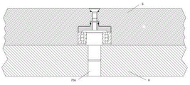
The upper workbench angle adjusting device 7 comprises a turbine 705, a worm 703, a driving motor III 701 and a coupler 702; the driving motor III 701 can drive the turbine 705 and the worm 703 to move through the coupler 702; the turbine 705 is provided on one side of the upper table 5; a rotating shaft 706 is arranged between the upper workbench 5 and the lower workbench 6, and the rotating shaft 706 is arranged between the tailstock device 3 and the headstock device 4; the contact surface between the upper working table 5 and the lower working table 6 at the rotating shaft 706 is scraped, so that the contact precision is improved, and the upper working table 5 and the lower working table 6 are tightly attached; the rotating shaft 706 comprises a centering rotating shaft, a conical self-aligning ball bearing, a clearance adjusting pressure plate and a countersunk head screw, and the lower half part of the centering rotating shaft is arranged in the lower workbench 6; the clearance adjusting pressure plate is arranged above the conical self-aligning ball bearing and is arranged at the upper part of the conical self-aligning ball bearing; the upper portion of circular cone self-aligning ball bearing is provided with countersunk screw, and countersunk screw's top and 5 upper surface levels of last workstation.
The upper table 5 is generally adjusted to an angle at which a side generatrix (on the grinding wheel 8 side) of the tapered surface of the shank to be machined is parallel to the guide rail direction of the lower table 6. The upper workbench 5 is adjusted to the angle, so that the cylindrical grinding and longitudinal grinding of the taper shank can be facilitated, and the shape precision and the surface roughness of the taper shank can be improved. The third driving motor 701 drives the coupler 702 and then drives the worm 703 to rotate, and the worm 703 drives the worm wheel 705 to slowly rotate at a constant speed, so as to finally control the upper workbench 5 to rotate around the rotating shaft 706. Wherein, this embodiment adopts worm and worm wheel drive ratio to be 1: 100 to achieve high controllable rotational accuracy.
When the angle is checked and finely adjusted through trial grinding, the parameters corresponding to the position can be recorded by the system, and the coordinate position recorded by the system can be directly driven when the angle is adjusted again next time. The pressing device 704 is in a released state during the angle adjustment process, and is in a pressed state after the angle adjustment process is completed.
The present invention can be easily implemented by those skilled in the art from the above detailed description. It should be understood, however, that the intention is not to limit the invention to the particular embodiments described. On the basis of the disclosed embodiments, a person skilled in the art can combine different technical features at will, thereby implementing different technical solutions.
Claims (10)
1. The utility model provides a numerical control end surface cylindrical grinder of high-efficient ultra-precision grinding high-speed handle of a knife which characterized in that: comprises a lathe bed, a grinding wheel frame, a tool shank outer diameter measuring instrument, an end surface measuring instrument, a tail frame device, a head frame device, an upper working table, a lower working table and an upper working table angle adjusting device; the lower workbench is arranged on the bed body, and the upper workbench is arranged on the lower workbench; the upper workbench angle adjusting device is arranged at one end of the short side of the upper workbench;
the tailstock device and the headstock device are arranged on the bed body, and the headstock device can move along the connecting line direction of the tailstock device and the headstock device;
the grinding wheel frame is arranged on the lathe body, a grinding wheel is arranged on the grinding wheel frame, and the grinding wheel is arranged on one side between the tail frame device and the head frame device;
the outer diameter measuring instrument of the tool handle is arranged between the tail frame device and the head frame device, and the end surface measuring instrument is arranged on one side of the grinding wheel and can measure the position of the side end surface of the workpiece.
2. The numerical control end surface cylindrical grinding machine for grinding the high-speed tool shank efficiently and ultraprecisely according to claim 1, is characterized in that: the tailstock device comprises a fixed base and a tailstock body, wherein one end of the upper workbench is provided with the fixed base, the fixed base is provided with two parallel linear guide rails, the tailstock body is installed on a sliding block of the linear guide rails, and the tailstock body can slide along the linear guide rails by 8-25 mm.
3. The numerical control end surface cylindrical grinding machine for grinding the high-speed tool shank efficiently and ultraprecisely as claimed in claim 2, is characterized in that: a driving motor is installed on one side of the tailstock body, which is far away from the grinding wheel, the driving motor drives a large belt pulley to rotate through a small belt pulley, and the large belt pulley is arranged at one end of a sleeve of the tailstock body; one side of the tailstock body is provided with a return spring and a contact switch, and the other side of the tailstock body is provided with a front stop block.
4. The numerical control end surface cylindrical grinding machine for grinding the high-speed tool shank efficiently and ultraprecisely as claimed in claim 2 or 3, wherein: one end of the tailstock body is provided with a tip; and a cooling liquid valve is arranged at the top of the tailstock body.
5. The numerical control end surface cylindrical grinding machine for grinding the high-speed tool shank efficiently and ultraprecisely as claimed in claim 2, is characterized in that: the headstock device comprises a headstock body and a fixed bottom plate, and the fixed bottom plate is arranged on the upper workbench through a screw; the linear guide rail is arranged on the fixed bottom plate; the head frame body is arranged on the sliding block between the linear guide rails, and the sliding block can drive the head frame body to slide along the linear guide rails by 300-500 mm; a driving motor II is arranged on one side of the headstock body, which is far away from the grinding wheel; the second driving motor is connected with a headstock main shaft; the lathe headstock is characterized in that a tip is arranged in a taper hole in one side of the headstock main shaft, a stepping motor is arranged on the other side of the headstock main shaft, a driving gear is installed at the shaft end of the stepping motor and meshed with a rack, and the rack is arranged on the fixed bottom plate and is parallel to the linear guide rail.
6. The numerical control end surface cylindrical grinding machine for grinding the high-speed tool shank efficiently and ultraprecisely as claimed in claim 5, is characterized in that: locking devices are arranged on the two sides of the driving gear and below the stepping motor; the locking device comprises a locking oil cylinder and a lever pressing arm.
7. The numerical control end surface cylindrical grinding machine for grinding the high-speed tool shank efficiently and ultraprecisely as claimed in claim 6, is characterized in that: a grating ruler is arranged on one side of the headstock device; and a V-shaped workpiece bracket is arranged between the tail frame device and the head frame device.
8. The numerical control end surface cylindrical grinding machine for grinding the high-speed tool shank efficiently and ultraprecisely according to claim 1, is characterized in that: the upper workbench angle adjusting device comprises a turbine, a worm, a driving motor III and a coupler; the driving motor can drive the worm wheel and the worm to move through the coupler; the turbine is arranged on one side of the upper workbench.
9. The numerical control end surface cylindrical grinding machine for grinding the high-speed tool shank efficiently and ultraprecisely as claimed in claim 8, is characterized in that: a rotating shaft is arranged between the upper workbench and the lower workbench and is arranged between the tailstock device and the headstock device; the rotating shaft uses a conical self-aligning ball bearing, and a joint surface between the upper workbench and the lower workbench is in close fit by scraping.
10. The numerical control end surface cylindrical grinding machine for grinding the high-speed tool shank efficiently and ultraprecisely according to claim 1, is characterized in that: the cooling system also comprises a cooling liquid box, wherein a constant-temperature air conditioner is arranged on the cooling liquid box; and a precision filter bag filter is arranged in the cooling liquid tank.
Priority Applications (1)
| Application Number | Priority Date | Filing Date | Title |
|---|---|---|---|
| CN202111332690.7A CN113910022A (en) | 2021-11-11 | 2021-11-11 | Numerical control end surface cylindrical grinder for efficiently and ultraprecisely grinding high-speed cutter handle |
Applications Claiming Priority (1)
| Application Number | Priority Date | Filing Date | Title |
|---|---|---|---|
| CN202111332690.7A CN113910022A (en) | 2021-11-11 | 2021-11-11 | Numerical control end surface cylindrical grinder for efficiently and ultraprecisely grinding high-speed cutter handle |
Publications (1)
| Publication Number | Publication Date |
|---|---|
| CN113910022A true CN113910022A (en) | 2022-01-11 |
Family
ID=79246157
Family Applications (1)
| Application Number | Title | Priority Date | Filing Date |
|---|---|---|---|
| CN202111332690.7A Pending CN113910022A (en) | 2021-11-11 | 2021-11-11 | Numerical control end surface cylindrical grinder for efficiently and ultraprecisely grinding high-speed cutter handle |
Country Status (1)
| Country | Link |
|---|---|
| CN (1) | CN113910022A (en) |
Cited By (3)
| Publication number | Priority date | Publication date | Assignee | Title |
|---|---|---|---|---|
| CN114608510A (en) * | 2022-03-29 | 2022-06-10 | 无锡连强智能装备有限公司 | Automatic outer diameter measuring device of lathe with accurate measuring effect |
| CN115164686A (en) * | 2022-09-08 | 2022-10-11 | 济南铸信机械有限公司 | Cone crusher barrel size detection device |
| CN117260411A (en) * | 2023-11-15 | 2023-12-22 | 河北力准机械制造有限公司 | Composite machining mechanism and tap machining grinding machine |
Citations (10)
| Publication number | Priority date | Publication date | Assignee | Title |
|---|---|---|---|---|
| USB325102I5 (en) * | 1973-01-19 | 1975-01-28 | ||
| CH623261A5 (en) * | 1978-07-14 | 1981-05-29 | Tschudin Werkzeugmasch | Process for the cylindrical grinding of cylindrical parts, and cylindrical grinding machine for carrying out this process |
| FR2512725A1 (en) * | 1981-09-14 | 1983-03-18 | Gendron Sa | Movable centre carriers for cylindrical grinder - uses mobile headstock drive along guide by lead screw actuated by NC electric motor |
| US4584795A (en) * | 1984-03-22 | 1986-04-29 | Toyoda Koki Kabushiki Kaisha | Numerical control grinding machine for grinding a taper portion of a workpiece |
| US4928437A (en) * | 1985-11-25 | 1990-05-29 | Werkzeugmaschinenfabrik Tschudin | Means and method for resetting a cylindrical grinding machine |
| US5555178A (en) * | 1992-11-17 | 1996-09-10 | Mitsubishi Denki Kabushiki Kaisha | Control apparatus and method for holding a workpiece in a machine tool |
| JPH10230458A (en) * | 1997-02-17 | 1998-09-02 | Okuma Mach Works Ltd | Taper grinding device |
| CN101776439A (en) * | 2010-02-10 | 2010-07-14 | 贵阳新天光电科技有限公司 | Variable light path laser length measuring machine |
| CN102252608A (en) * | 2010-04-21 | 2011-11-23 | 特莎有限公司 | Optical measurement method and apparatus |
| CN108788959A (en) * | 2018-07-13 | 2018-11-13 | 北京工业大学 | A kind of vertical grinder for the conical surface and taper hole grinding |
-
2021
- 2021-11-11 CN CN202111332690.7A patent/CN113910022A/en active Pending
Patent Citations (10)
| Publication number | Priority date | Publication date | Assignee | Title |
|---|---|---|---|---|
| USB325102I5 (en) * | 1973-01-19 | 1975-01-28 | ||
| CH623261A5 (en) * | 1978-07-14 | 1981-05-29 | Tschudin Werkzeugmasch | Process for the cylindrical grinding of cylindrical parts, and cylindrical grinding machine for carrying out this process |
| FR2512725A1 (en) * | 1981-09-14 | 1983-03-18 | Gendron Sa | Movable centre carriers for cylindrical grinder - uses mobile headstock drive along guide by lead screw actuated by NC electric motor |
| US4584795A (en) * | 1984-03-22 | 1986-04-29 | Toyoda Koki Kabushiki Kaisha | Numerical control grinding machine for grinding a taper portion of a workpiece |
| US4928437A (en) * | 1985-11-25 | 1990-05-29 | Werkzeugmaschinenfabrik Tschudin | Means and method for resetting a cylindrical grinding machine |
| US5555178A (en) * | 1992-11-17 | 1996-09-10 | Mitsubishi Denki Kabushiki Kaisha | Control apparatus and method for holding a workpiece in a machine tool |
| JPH10230458A (en) * | 1997-02-17 | 1998-09-02 | Okuma Mach Works Ltd | Taper grinding device |
| CN101776439A (en) * | 2010-02-10 | 2010-07-14 | 贵阳新天光电科技有限公司 | Variable light path laser length measuring machine |
| CN102252608A (en) * | 2010-04-21 | 2011-11-23 | 特莎有限公司 | Optical measurement method and apparatus |
| CN108788959A (en) * | 2018-07-13 | 2018-11-13 | 北京工业大学 | A kind of vertical grinder for the conical surface and taper hole grinding |
Cited By (6)
| Publication number | Priority date | Publication date | Assignee | Title |
|---|---|---|---|---|
| CN114608510A (en) * | 2022-03-29 | 2022-06-10 | 无锡连强智能装备有限公司 | Automatic outer diameter measuring device of lathe with accurate measuring effect |
| CN114608510B (en) * | 2022-03-29 | 2023-11-24 | 无锡连强智能装备有限公司 | Automatic external diameter measuring device of lathe with accurate measurement effect |
| CN115164686A (en) * | 2022-09-08 | 2022-10-11 | 济南铸信机械有限公司 | Cone crusher barrel size detection device |
| CN115164686B (en) * | 2022-09-08 | 2022-11-08 | 济南铸信机械有限公司 | Cone crusher barrel size detection device |
| CN117260411A (en) * | 2023-11-15 | 2023-12-22 | 河北力准机械制造有限公司 | Composite machining mechanism and tap machining grinding machine |
| CN117260411B (en) * | 2023-11-15 | 2024-02-13 | 河北力准机械制造有限公司 | Composite machining mechanism and tap machining grinding machine |
Similar Documents
| Publication | Publication Date | Title |
|---|---|---|
| CN113910022A (en) | Numerical control end surface cylindrical grinder for efficiently and ultraprecisely grinding high-speed cutter handle | |
| CN209793106U (en) | Turning and grinding integrated numerical control composite machine tool | |
| CN111618670A (en) | Adjustable twist drill grinding device | |
| CN112720224A (en) | Large-diameter high-precision abrasive wheel cutting machine | |
| CN110181347B (en) | Remanufacturing automatic numerical control crankshaft grinding machine | |
| CN2838853Y (en) | Semi-automatic micro-ball bearing ring multipurpose grinding machine | |
| CN216883179U (en) | Head walking type follow-up grinding machine suitable for processing inner and outer curves | |
| CN109909753A (en) | Vehicle grinds integrated composite numerical control machine tool | |
| CN203401361U (en) | Numerically-controlled grinding machine for screw tap | |
| CN110549198A (en) | Internal spherical surface grinding machine | |
| CN215788632U (en) | Grinding device of cylindrical grinding machine | |
| CN220761676U (en) | Positioning mechanism for metal cutting machine tool | |
| CN205733094U (en) | A kind of multi-shaft interlocked hole processing device | |
| CN219747532U (en) | Numerical control screw tap thread machining center | |
| CN220561172U (en) | High-precision numerical control roller grinding machine | |
| CN215148007U (en) | Quick workpiece changing structure of high-precision polishing machine | |
| CN210281647U (en) | Special equipment for machining screw tap die | |
| CN219819296U (en) | Numerical control deep hole honing machine | |
| CN217194302U (en) | Cutter excircle grinding machine tool | |
| CN219255111U (en) | High-precision automatic machine tool device | |
| CN214186764U (en) | Screw tap thread grinder fixture | |
| CN217019672U (en) | Excircle grinding equipment | |
| CN218639210U (en) | Full-automatic numerical control screw tap thread grinder | |
| CN217619479U (en) | Automatic cylindrical grinding machine for shaft parts | |
| CN212886889U (en) | Ditching and back-turning numerical control tool grinding machine for drill bit and milling cutter |
Legal Events
| Date | Code | Title | Description |
|---|---|---|---|
| PB01 | Publication | ||
| PB01 | Publication | ||
| SE01 | Entry into force of request for substantive examination | ||
| SE01 | Entry into force of request for substantive examination |