CN113825054A - Head-wearing type voice communication device - Google Patents
Head-wearing type voice communication device Download PDFInfo
- Publication number
- CN113825054A CN113825054A CN202010557805.1A CN202010557805A CN113825054A CN 113825054 A CN113825054 A CN 113825054A CN 202010557805 A CN202010557805 A CN 202010557805A CN 113825054 A CN113825054 A CN 113825054A
- Authority
- CN
- China
- Prior art keywords
- audio
- head
- bone conduction
- audio device
- control unit
- Prior art date
- Legal status (The legal status is an assumption and is not a legal conclusion. Google has not performed a legal analysis and makes no representation as to the accuracy of the status listed.)
- Granted
Links
- 238000004891 communication Methods 0.000 title description 16
- 210000000988 bone and bone Anatomy 0.000 claims abstract description 94
- 230000005236 sound signal Effects 0.000 claims abstract description 69
- 238000000034 method Methods 0.000 claims abstract description 5
- 230000003750 conditioning effect Effects 0.000 claims description 11
- 230000008878 coupling Effects 0.000 claims description 11
- 238000010168 coupling process Methods 0.000 claims description 11
- 238000005859 coupling reaction Methods 0.000 claims description 11
- 238000005286 illumination Methods 0.000 claims description 8
- 229910000859 α-Fe Inorganic materials 0.000 claims description 6
- 230000003213 activating effect Effects 0.000 claims description 4
- 230000000712 assembly Effects 0.000 claims description 3
- 238000000429 assembly Methods 0.000 claims description 3
- 238000010586 diagram Methods 0.000 description 20
- 230000006870 function Effects 0.000 description 20
- 230000005540 biological transmission Effects 0.000 description 13
- 239000003990 capacitor Substances 0.000 description 13
- 241000282414 Homo sapiens Species 0.000 description 10
- 230000002829 reductive effect Effects 0.000 description 8
- 229910000831 Steel Inorganic materials 0.000 description 5
- 239000010959 steel Substances 0.000 description 5
- 230000003321 amplification Effects 0.000 description 4
- 239000004020 conductor Substances 0.000 description 4
- 238000001514 detection method Methods 0.000 description 4
- 239000003292 glue Substances 0.000 description 4
- 239000000463 material Substances 0.000 description 4
- 230000004048 modification Effects 0.000 description 4
- 238000012986 modification Methods 0.000 description 4
- 238000003199 nucleic acid amplification method Methods 0.000 description 4
- 239000004033 plastic Substances 0.000 description 4
- 230000010287 polarization Effects 0.000 description 4
- 210000003625 skull Anatomy 0.000 description 4
- 230000006872 improvement Effects 0.000 description 3
- 230000005865 ionizing radiation Effects 0.000 description 3
- 229910052751 metal Inorganic materials 0.000 description 3
- 239000002184 metal Substances 0.000 description 3
- 230000008569 process Effects 0.000 description 3
- 239000000725 suspension Substances 0.000 description 3
- 238000013459 approach Methods 0.000 description 2
- 230000008901 benefit Effects 0.000 description 2
- 230000001413 cellular effect Effects 0.000 description 2
- 210000005069 ears Anatomy 0.000 description 2
- 230000000694 effects Effects 0.000 description 2
- 230000005684 electric field Effects 0.000 description 2
- 230000014509 gene expression Effects 0.000 description 2
- PXHVJJICTQNCMI-UHFFFAOYSA-N nickel Substances [Ni] PXHVJJICTQNCMI-UHFFFAOYSA-N 0.000 description 2
- 230000036961 partial effect Effects 0.000 description 2
- 230000004044 response Effects 0.000 description 2
- 210000004872 soft tissue Anatomy 0.000 description 2
- 230000007704 transition Effects 0.000 description 2
- RNFJDJUURJAICM-UHFFFAOYSA-N 2,2,4,4,6,6-hexaphenoxy-1,3,5-triaza-2$l^{5},4$l^{5},6$l^{5}-triphosphacyclohexa-1,3,5-triene Chemical compound N=1P(OC=2C=CC=CC=2)(OC=2C=CC=CC=2)=NP(OC=2C=CC=CC=2)(OC=2C=CC=CC=2)=NP=1(OC=1C=CC=CC=1)OC1=CC=CC=C1 RNFJDJUURJAICM-UHFFFAOYSA-N 0.000 description 1
- RYGMFSIKBFXOCR-UHFFFAOYSA-N Copper Chemical compound [Cu] RYGMFSIKBFXOCR-UHFFFAOYSA-N 0.000 description 1
- HBBGRARXTFLTSG-UHFFFAOYSA-N Lithium ion Chemical compound [Li+] HBBGRARXTFLTSG-UHFFFAOYSA-N 0.000 description 1
- 238000010521 absorption reaction Methods 0.000 description 1
- 230000004913 activation Effects 0.000 description 1
- 239000002390 adhesive tape Substances 0.000 description 1
- 230000036626 alertness Effects 0.000 description 1
- 229910052782 aluminium Inorganic materials 0.000 description 1
- XAGFODPZIPBFFR-UHFFFAOYSA-N aluminium Chemical compound [Al] XAGFODPZIPBFFR-UHFFFAOYSA-N 0.000 description 1
- 238000004458 analytical method Methods 0.000 description 1
- 230000002238 attenuated effect Effects 0.000 description 1
- 239000011324 bead Substances 0.000 description 1
- 230000009286 beneficial effect Effects 0.000 description 1
- 230000000903 blocking effect Effects 0.000 description 1
- 210000001715 carotid artery Anatomy 0.000 description 1
- 239000011248 coating agent Substances 0.000 description 1
- 238000000576 coating method Methods 0.000 description 1
- 230000003111 delayed effect Effects 0.000 description 1
- 238000011161 development Methods 0.000 description 1
- 238000005516 engineering process Methods 0.000 description 1
- 230000002708 enhancing effect Effects 0.000 description 1
- 230000007613 environmental effect Effects 0.000 description 1
- 230000005294 ferromagnetic effect Effects 0.000 description 1
- 238000001914 filtration Methods 0.000 description 1
- 239000003063 flame retardant Substances 0.000 description 1
- 239000011521 glass Substances 0.000 description 1
- 230000005484 gravity Effects 0.000 description 1
- 230000036541 health Effects 0.000 description 1
- 210000000003 hoof Anatomy 0.000 description 1
- 239000012943 hotmelt Substances 0.000 description 1
- 229910001416 lithium ion Inorganic materials 0.000 description 1
- GELKBWJHTRAYNV-UHFFFAOYSA-K lithium iron phosphate Chemical compound [Li+].[Fe+2].[O-]P([O-])([O-])=O GELKBWJHTRAYNV-UHFFFAOYSA-K 0.000 description 1
- 230000007774 longterm Effects 0.000 description 1
- 230000005291 magnetic effect Effects 0.000 description 1
- 239000000696 magnetic material Substances 0.000 description 1
- 238000002844 melting Methods 0.000 description 1
- 230000008018 melting Effects 0.000 description 1
- 229910052987 metal hydride Inorganic materials 0.000 description 1
- 210000003205 muscle Anatomy 0.000 description 1
- 229910052759 nickel Inorganic materials 0.000 description 1
- 229910000652 nickel hydride Inorganic materials 0.000 description 1
- -1 nickel metal hydride Chemical class 0.000 description 1
- 230000000149 penetrating effect Effects 0.000 description 1
- 230000008447 perception Effects 0.000 description 1
- 239000002985 plastic film Substances 0.000 description 1
- 229920006255 plastic film Polymers 0.000 description 1
- 239000002861 polymer material Substances 0.000 description 1
- 229920001296 polysiloxane Polymers 0.000 description 1
- 238000012545 processing Methods 0.000 description 1
- 230000002035 prolonged effect Effects 0.000 description 1
- 230000001681 protective effect Effects 0.000 description 1
- 238000011084 recovery Methods 0.000 description 1
- 239000011347 resin Substances 0.000 description 1
- 229920005989 resin Polymers 0.000 description 1
- 230000002441 reversible effect Effects 0.000 description 1
- 230000008054 signal transmission Effects 0.000 description 1
- 229920001169 thermoplastic Polymers 0.000 description 1
- 239000004416 thermosoftening plastic Substances 0.000 description 1
- 210000003437 trachea Anatomy 0.000 description 1
Images


Classifications
-
- H—ELECTRICITY
- H04—ELECTRIC COMMUNICATION TECHNIQUE
- H04R—LOUDSPEAKERS, MICROPHONES, GRAMOPHONE PICK-UPS OR LIKE ACOUSTIC ELECTROMECHANICAL TRANSDUCERS; DEAF-AID SETS; PUBLIC ADDRESS SYSTEMS
- H04R1/00—Details of transducers, loudspeakers or microphones
- H04R1/10—Earpieces; Attachments therefor ; Earphones; Monophonic headphones
- H04R1/1008—Earpieces of the supra-aural or circum-aural type
-
- H—ELECTRICITY
- H04—ELECTRIC COMMUNICATION TECHNIQUE
- H04B—TRANSMISSION
- H04B1/00—Details of transmission systems, not covered by a single one of groups H04B3/00 - H04B13/00; Details of transmission systems not characterised by the medium used for transmission
- H04B1/38—Transceivers, i.e. devices in which transmitter and receiver form a structural unit and in which at least one part is used for functions of transmitting and receiving
- H04B1/3827—Portable transceivers
-
- H—ELECTRICITY
- H04—ELECTRIC COMMUNICATION TECHNIQUE
- H04Q—SELECTING
- H04Q5/00—Selecting arrangements wherein two or more subscriber stations are connected by the same line to the exchange
- H04Q5/24—Selecting arrangements wherein two or more subscriber stations are connected by the same line to the exchange for two-party-line systems
-
- H—ELECTRICITY
- H04—ELECTRIC COMMUNICATION TECHNIQUE
- H04R—LOUDSPEAKERS, MICROPHONES, GRAMOPHONE PICK-UPS OR LIKE ACOUSTIC ELECTROMECHANICAL TRANSDUCERS; DEAF-AID SETS; PUBLIC ADDRESS SYSTEMS
- H04R1/00—Details of transducers, loudspeakers or microphones
- H04R1/08—Mouthpieces; Microphones; Attachments therefor
-
- H—ELECTRICITY
- H04—ELECTRIC COMMUNICATION TECHNIQUE
- H04R—LOUDSPEAKERS, MICROPHONES, GRAMOPHONE PICK-UPS OR LIKE ACOUSTIC ELECTROMECHANICAL TRANSDUCERS; DEAF-AID SETS; PUBLIC ADDRESS SYSTEMS
- H04R1/00—Details of transducers, loudspeakers or microphones
- H04R1/10—Earpieces; Attachments therefor ; Earphones; Monophonic headphones
-
- H—ELECTRICITY
- H04—ELECTRIC COMMUNICATION TECHNIQUE
- H04R—LOUDSPEAKERS, MICROPHONES, GRAMOPHONE PICK-UPS OR LIKE ACOUSTIC ELECTROMECHANICAL TRANSDUCERS; DEAF-AID SETS; PUBLIC ADDRESS SYSTEMS
- H04R3/00—Circuits for transducers, loudspeakers or microphones
-
- H—ELECTRICITY
- H04—ELECTRIC COMMUNICATION TECHNIQUE
- H04R—LOUDSPEAKERS, MICROPHONES, GRAMOPHONE PICK-UPS OR LIKE ACOUSTIC ELECTROMECHANICAL TRANSDUCERS; DEAF-AID SETS; PUBLIC ADDRESS SYSTEMS
- H04R2201/00—Details of transducers, loudspeakers or microphones covered by H04R1/00 but not provided for in any of its subgroups
- H04R2201/10—Details of earpieces, attachments therefor, earphones or monophonic headphones covered by H04R1/10 but not provided for in any of its subgroups
-
- H—ELECTRICITY
- H04—ELECTRIC COMMUNICATION TECHNIQUE
- H04R—LOUDSPEAKERS, MICROPHONES, GRAMOPHONE PICK-UPS OR LIKE ACOUSTIC ELECTROMECHANICAL TRANSDUCERS; DEAF-AID SETS; PUBLIC ADDRESS SYSTEMS
- H04R2203/00—Details of circuits for transducers, loudspeakers or microphones covered by H04R3/00 but not provided for in any of its subgroups
-
- H—ELECTRICITY
- H04—ELECTRIC COMMUNICATION TECHNIQUE
- H04R—LOUDSPEAKERS, MICROPHONES, GRAMOPHONE PICK-UPS OR LIKE ACOUSTIC ELECTROMECHANICAL TRANSDUCERS; DEAF-AID SETS; PUBLIC ADDRESS SYSTEMS
- H04R2410/00—Microphones
-
- H—ELECTRICITY
- H04—ELECTRIC COMMUNICATION TECHNIQUE
- H04R—LOUDSPEAKERS, MICROPHONES, GRAMOPHONE PICK-UPS OR LIKE ACOUSTIC ELECTROMECHANICAL TRANSDUCERS; DEAF-AID SETS; PUBLIC ADDRESS SYSTEMS
- H04R2460/00—Details of hearing devices, i.e. of ear- or headphones covered by H04R1/10 or H04R5/033 but not provided for in any of their subgroups, or of hearing aids covered by H04R25/00 but not provided for in any of its subgroups
- H04R2460/13—Hearing devices using bone conduction transducers
Landscapes
- Engineering & Computer Science (AREA)
- Signal Processing (AREA)
- Physics & Mathematics (AREA)
- Acoustics & Sound (AREA)
- Computer Networks & Wireless Communication (AREA)
- Telephone Set Structure (AREA)
- Circuit For Audible Band Transducer (AREA)
Abstract
An embodiment of the present disclosure provides a head-mounted voice call device, including: a head-mounted frame; the first audio equipment is arranged on the head-mounted frame and is fixedly connected with the head-mounted frame; the first bone conduction vibrator and the second bone conduction vibrator are respectively arranged on the head-wearing type frame and are fixedly connected with the head-wearing type frame; and a control unit disposed on the head-mounted frame and electrically coupled with the first audio device, the first bone conduction vibrator, the second bone conduction vibrator, and the second audio device, wherein the control unit is configured to: receiving a first audio signal from a first audio device and outputting the first audio signal via a first bone conduction vibrator; and receiving a second audio signal from a second audio device and outputting via a second bone conduction transducer. With the above method, audio signals of the first audio device and the second audio device can be output via the two bone conduction vibrators, respectively, without switching.
Description
Technical Field
The present disclosure relates to wearable audio accessories, and more particularly, to a head-mounted voice communicator.
Background
The use of the interphone has been gradually popularized in the fields of life scenes such as outdoor sports, group driving, international travel and the like, and operations such as security, special and the like. However, the conventional walkie-talkie is not portable, and needs to be removed from a fixed location (such as a belt) when responding to a call, which causes a call delay, and a speaker of the walkie-talkie is affected by environmental noise to cause a call quality to be degraded, and even a call sound is not heard, which causes no response.
In the prior art, in order to solve the above problems, an audio accessory integrated with an earphone, a microphone and a push button (PTT) of an interphone is proposed. The audio accessory connects the earphone, the microphone, the interphone PTT and the interphone body through the cable to realize the interphone voice communication.
Still some prior art's schemes adopt bluetooth headset or bluetooth PTT to connect the intercom to avoid using the potential safety hazard of unexpected fatal events such as trip, tumble, cut neck trachea, carotid artery even that longer cable conductor brought. Other prior art solutions have embedded an intercom in the space between the inside of the helmet and the skull to secure the intercom.
Disclosure of Invention
Although the audio accessory integrated with the earphone, the microphone and the PTT can realize a timely response to a call, the overlong cable and the operation of the PTT with fingers can bring other potential safety hazards to users. Moreover, after the earphone is inserted into the auditory canal, the perception degree of surrounding environment sound is reduced, and therefore a new potential safety hazard is formed.
In addition, although the scheme of adopting the bluetooth headset or the bluetooth PTT can avoid using a cable, the bluetooth is suitable for short-distance audio transmission, crosses obstacles, has weak wall penetrating capability, is easily interfered when an electromagnetic environment is complex, blocks a frequency band or is intercepted, and the reliability is reduced by an extra power supply system required by the bluetooth headset or the bluetooth PTT. Fixing the intercom inside the helmet not only reduces the protective capacity of the helmet and the antenna transmission efficiency of the intercom antenna, but also increases the non-ionizing radiation Absorption exposure Rate (SAR) of the user.
The present disclosure provides a head-mounted voice call apparatus. A first embodiment of the present disclosure provides a head-mounted voice call apparatus, including: a head-mounted frame; the first audio equipment is arranged on the head-mounted frame and is fixedly connected with the head-mounted frame; the first bone conduction vibrator and the second bone conduction vibrator are respectively arranged on the head-wearing type frame and are fixedly connected with the head-wearing type frame; and a control unit disposed on the head-mounted frame and electrically coupled with the first audio device, the first bone conduction vibrator, the second bone conduction vibrator, and the second audio device, wherein the control unit is configured to: receiving a first audio signal from a first audio device and outputting the first audio signal via a first bone conduction vibrator; and receiving a second audio signal from a second audio device and outputting via a second bone conduction transducer.
In this embodiment, the audio signals of the first audio device and the second audio device can be output via the two bone conduction vibrators respectively without switching (as if intercom call and voice navigation are realized in real time), which makes full use of the capability of the left and right ears of human beings to simultaneously receive the audio signals transmitted by the two devices. Moreover, the bone conduction vibrator can enable a user to keep alert of surrounding environment sounds while listening to audio signals, potential safety hazards are reduced, and interference of a loudspeaker of a traditional interphone to the surrounding environment is reduced.
In a preferred example, the control unit further includes: an audio amplifier electrically coupled to the audio output of the second audio device to selectively amplify the second audio signal; and an audio amplifier switch configured to: when the first position is located, the second audio signal is amplified by the audio amplifier and then output through the second bone conduction vibrator; and when in the second position, causing the second audio signal to be output directly via the second bone conduction vibrator.
In a preferred example, the control unit further comprises an amplifier control module configured to: activating the audio amplifier to amplify the second audio signal when the audio amplifier switch is in the first position; and deactivating the audio amplifier when the audio amplifier switch is in the second position.
In a preferred example, the control unit further comprises a signal adjustment module electrically coupled to the audio output of the second audio device and configured to compensate for low frequency signals in the second audio signal before the second audio signal is amplified when the audio amplifier switch is in the first position.
In a preferred example, the headset further includes a first microphone and a second microphone fixedly connected to the headset frame, respectively, and electrically coupled to the control unit for inputting audio signals to audio input terminals of the first audio device and the second audio device, respectively.
In a preferred example, the control unit further comprises an audio forwarding switch configured to: electrically coupling a first microphone to an audio input of a first audio device and a second microphone to an audio input of a second audio device when in a first position; and electrically coupling the audio output of the first audio device with the audio input of the second audio device and electrically coupling the audio output of the second audio device with the audio input of the first audio device when in the second position.
In a preferred example, the first microphone and the second microphone are electrically coupled with the control unit via a cable line, and the apparatus further comprises a radio frequency ground line electrically coupled with a ground terminal of the first audio device, the radio frequency ground line being arranged in parallel with the cable line.
In a preferred example, the headset further comprises at least one rechargeable battery for powering the first audio device and the control unit, wherein the first audio device comprises a charging module configured to control charging of the at least one rechargeable battery.
In a preferred example, the first audio device is an intercom and the second audio device is any one of a mobile phone, an intercom or a bluetooth adapter.
In a preferred example, the head-mounted frame comprises a top head load-bearing band and a hollow semi-toroidal frame, wherein the control unit is electrically coupled with the first audio device, the first bone conduction vibrator, the second bone conduction vibrator and the second audio device via a cable housed within the semi-toroidal frame, and the apparatus further comprises a ferrite bead sleeved over the semi-toroidal frame.
In a preferred example, the head-mounted voice communicator further comprises a pair of cushion members, each cushion member comprising a card slot for receiving the first bone conduction vibrator or the second bone conduction vibrator, a hollow support tray fixedly connected with the card slot for receiving the gel, and a gel, wherein the gel is in direct contact with the first bone conduction vibrator or the second bone conduction vibrator when the first bone conduction vibrator or the second bone conduction vibrator is received in the card slot.
In a preferred example, the head-mounted voice communicator further comprises a deflector prism and the first audio device comprises an illumination device, wherein the deflector prism is used for receiving and deflecting light emitted by the illumination device.
In a preferred example, the second audio device is detachably connected to the head-mounted voice call apparatus.
Drawings
Embodiments are shown and described with reference to the drawings. These drawings are provided to illustrate the basic principles and thus only show the aspects necessary for understanding the basic principles. The figures are not to scale. In the drawings, like reference numerals designate similar features.
FIG. 1 illustrates an exemplary block diagram of one angle of a head-mounted voice communicator according to one embodiment of the present disclosure;
FIG. 2 illustrates an exemplary block diagram of another perspective of the head-mounted voice communicator of FIG. 1;
fig. 3 is a diagram illustrating an exemplary configuration of a function control box area of the head-mounted voice call apparatus of fig. 1;
FIG. 4 illustrates an exemplary circuit diagram of an audio amplifier switch of the voice-over-head device of FIG. 1;
FIG. 5 illustrates an exemplary circuit diagram of an audio amplifier and signal conditioning module of the voice-over-head device of FIG. 1;
FIG. 6 illustrates an exemplary circuit diagram of an amplifier control module of the voice headset of FIG. 1;
FIG. 7 illustrates an exemplary circuit diagram of an audio relay switch of the voice-over-head device of FIG. 1;
fig. 8 is a diagram illustrating an exemplary configuration of a microphone mounting manner of the head-mounted voice call apparatus of fig. 1;
FIG. 9 illustrates an exemplary circuit diagram of a charging module of the intercom of FIG. 1;
figures 10(a) - (c) illustrate exemplary block diagrams of a pair of cushion assemblies of figure 1; and
fig. 11(a) - (b) show two examples of a polarization prism mounted on the intercom of fig. 1, respectively.
Detailed Description
The making and using of specific embodiments are described in detail below. It should be understood, however, that the specific embodiments discussed are merely illustrative of specific ways to make and use the disclosure, and do not limit the scope of the disclosure. In the description, the structural positions of the respective components, such as the directions of up, down, top, bottom, etc., are not absolutely expressed, but are relative. When the respective components are arranged as shown in the drawings, these direction expressions are appropriate, but when the positions of the respective components in the drawings are changed, these direction expressions are changed accordingly. As used herein, the terms "connected" or "coupled," and the like, are not limited to physical or mechanical connections, but may include electrical connections, whether direct or indirect. The terms "first," "second," and the like, do not denote any order, quantity, or importance, but rather are used to distinguish one element from another. Also, the use of the terms "a" or "an" and the like do not denote a limitation of quantity, but rather denote the presence of at least one.
As used herein, the terms "comprising," "including," and similar terms are open-ended terms, i.e., "including/including but not limited to," meaning that additional content may also be included. The term "one embodiment" means "at least one embodiment"; the term "another embodiment" means "at least one additional embodiment," and the like. In this specification, the schematic representations of the terms used above are not necessarily intended to refer to the same embodiment or example. Furthermore, the particular features, structures, materials, or characteristics described may be combined in any suitable manner in any one or more embodiments or examples. Furthermore, various embodiments or examples and features of different embodiments or examples described in this specification can be combined and combined by one skilled in the art without contradiction.
As mentioned above, overlong cables, finger-operated PTT and in-ear headphones all cause potential safety hazards to users, and the distance and reliability of audio transmission can be affected by connecting a bluetooth headset or bluetooth PTT with an intercom. In addition, the interphone is fixed inside the helmet, so that the protection capability of the helmet and the antenna emission efficiency of the interphone antenna are reduced, and the non-ionizing radiation exposure of a user is increased.
In order to solve the above problems, the present invention provides a head-mounted voice communication device. Embodiments of the present disclosure are described in detail below with reference to fig. 1-11 as examples.
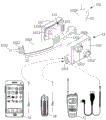
Reference is first made to fig. 1 and 2. Fig. 1 illustrates an exemplary block diagram of one angle of a head-mounted voice call apparatus according to an embodiment of the present disclosure, and fig. 2 illustrates an exemplary block diagram of another angle of the head-mounted voice call apparatus in fig. 1. In the present embodiment, the head-mounted voice communicator 100 includes a head-mounted frame 10, a first audio device 11, a first bone conduction vibrator 12, a second bone conduction vibrator 12 ', a function control box 13, a first battery box 14 and a second battery box 14 ', a microphone assembly 15, a bluetooth audio adapter 16, a ferromagnetic ring 17, a pair of cushion assemblies 18 and 18 ', and a deflector prism 19. In the present embodiment, the first audio device 11 is a VOX (voice activated transmission) small interphone. In other embodiments, first audio device 11 and second audio device 16 may be any audio device capable of outputting audio signals. For convenience of explanation, the head-mounted voice call apparatus of the present disclosure will be specifically described below by taking the first audio device 11 as an example of an intercom. In other embodiments, the first audio device 11 may be any other type of audio device.
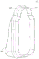
As shown in fig. 1 and 2, the head-mounted frame 10 is composed of a top load-bearing belt 101 and a hollow semi-annular frame 102. When the user wears the head-mounted voice communicator 100, the semi-ring frame 102 is located at the occiput of the back of the user's skull, and the overhead weight-bearing belts 101 are fixed on both sides of the semi-ring frame 102 by passing around the top of the user's head. The weight of the whole head-mounted voice communication device 100 is mainly dispersed to the top of the head through the top-head bearing belt 101, and also is partially borne by the clamping force and the friction force of the first bone conduction vibrator 12 and the second bone conduction vibrator 12' after being deformed by the semi-annular frame 102. . The head-mounted voice communication device can be used in the fields of life scenes such as outdoor sports, group driving and the like, security, special operations and the like, and when a user wears a half-wrapped sports helmet, a worker safety helmet or a tactical helmet, the semi-ring-shaped frame 102 is positioned at the lower edge of the helmet or the safety helmet, so that the wearing of the helmet or the safety helmet is not influenced.
In this embodiment, the overhead bearing belt 101 is a self-adhesive tape having a width of about 20mm, and a length thereof can be adjusted according to an actual wearing condition, and the semi-ring frame 102 is formed of an elastic steel wire having a diameter of about 1mm as a main supporting member. In other embodiments, the overhead weight belt 101 may be made of other materials (e.g., plastic) or other widths (e.g., widths between 1-50 mm), and the semi-annular frame 102 may be supported by other resilient structures (e.g., resilient plastic structures) or by resilient steel wires of other dimensions (e.g., diameters between 0.5mm-3 mm). In other embodiments, the head-mounted frame 10 may have other structures as long as it can be stably worn on the head of the user.
By using the overhead carrying belt 101 and the semi-ring frame 102, the head-mounted voice communicator 100 can be independently and stably worn on the head of a user and can be compatible with a semi-packaged sports helmet, a worker's helmet and a tactical helmet.
With continued reference to fig. 1 and 2, the first and second bone conduction elements 12 and 12' are fixedly mounted at the left and right ends of the semi-ring frame 102, respectively. The intercom 11 is fixedly connected with the first bone conduction vibrator 12 via a fastener such as a screw, and therefore the intercom 11 is fixedly connected to the head mount frame 10 via the first bone conduction vibrator 12. The function control box 13 is fixedly installed on the semi-annular frame 102, and a first battery box 14 and a second battery box 14' are respectively installed at both sides thereof. One or more AA size (nominal diameter 14mm x length 50mm) batteries (e.g., 1.2V nickel metal hydride, 1.5V alkaline, 3.7V/3.85V lithium ion, 3.2V lithium iron phosphate, etc.) may be disposed in each of the first and second battery compartments 14, 14', and may be connected in series or in parallel to provide power to the headset 100. In the present embodiment, the first battery pack 14 and the second battery pack 14' are a single AA battery pack and a double AA battery pack, respectively, and three AA batteries are connected in series to supply power. The mounting positions of the first battery box 14, the function control box 13 and the second battery box 14' on the semi-ring frame 102 are set to keep the center of gravity of the whole head-mounted voice communicator 100 near the tongue root of the user, so that the extra driving moment required by the muscles of the head and neck of the user is small, thereby improving the wearing experience of the user.
In addition, in cold seasons, people usually wear clothes such as cotton-padded clothes, rain coats, hooves and the like with hats, and thus a warm and dry cavity is formed at the back of the skull. As mentioned above, the semi-annular frame 102 is located at the occiput of the back of the skull when worn by the user, and therefore the positions of the first battery compartment 14, the function control compartment 13, and the second battery compartment 14 'are located within this cavity, thereby improving the weather resistance of the battery components within the first battery compartment 14 and the second battery compartment 14', and therefore the entire head-mounted voice communicator 100, in severe environments such as cold, weather, and the like.
Referring now to fig. 3, fig. 3 illustrates an exemplary block diagram of a function control box area of the head-mounted voice communicator of fig. 1. As shown in fig. 3, the function control box 13 includes three parts of a control unit 131, a first box 132, and a second box 133. The edges of the first case 132 and the second case 133 are respectively provided with semicircular slots so that the elastic steel wire 1021, the cable wires 1022 and 1024, and the battery case leads 21 and 22 of the semi-ring frame 102 pass through the slots and are electrically coupled with the control unit 131 when being snapped together. The first case 132 and the second case 133 may be made of plastic. Through fixing intercom 11, first bone conduction oscillator 12, second bone conduction oscillator 12 'and function control box 13 on head-mounted frame 10, can accomodate the cable conductor in semi-ring frame 102, still guaranteed audio transmission's effect when avoiding the cable conductor to expose the potential safety hazard that brings, can not bring extra non-ionizing radiation for the user yet. The control unit 131 includes a circuit board 1310, an audio amplifier switch 1311, an audio relay switch 1312, an internal audio jack 1313, an audio amplifier, an amplifier control module, and a signal conditioning module (not shown in fig. 3, which will be described in detail below).
In this embodiment, the cable 1022 is a twelve-core cable, and is composed of two power lines (e.g. 26AWG wires) and 10 signal lines (e.g. enameled wires with a diameter of 0.2-0.3 mm), and these power lines and signal lines are disposed close to the elastic steel wire 1021. The 10 signal lines of the cable lines 1022 each indicate one end electrically connected to the following terminals: (1) a first microphone audio output positive pole; (2) a microphone ground; (3) a second microphone audio output positive pole; (4) a battery temperature sensor; (5) the audio input anode of the interphone; (6) the audio input ground of the interphone; (7) the audio output anode of the interphone; (8) the audio output cathode of the interphone; (9) the audio input anode of the first bone conduction vibrator; (10) the audio frequency of the first bone conduction vibrator is input into the cathode. One end of each of the two power lines of the cable 1022 is electrically connected to the positive and negative power input terminals of the intercom 11. The other ends of the signal and power lines of the cable lines 1022 are soldered directly to the circuit board 1310.
In this embodiment, the cable 1024 is composed of two signal wires (e.g., enameled wires with a diameter of 0.2-0.3 mm) placed against the elastic wire 1021. One end of each of the two signal wires of the cable 1024 is electrically connected to the following connecting terminal: (1) the second bone conduction vibrator 12' is audio-frequency input positive pole; (2) the second bone conduction element 12' is audio input negative. The other ends of the two signal wires of the cable wires 1024 are soldered directly to the circuit board 1310. Two sheath tubes 1023 and 1023' made of flame retardant insulating plastic material (such as heat shrinkable sheath tube with inner diameter of 4.0-4.5 mm) are respectively sleeved outside the cable wires 1022 and 1024. Two sets of battery box wires 21 and 22 are respectively disposed outside the sheath tubes 1023 and 1023 ', one end of each battery box wire is electrically connected to the rechargeable batteries in the first battery box 14 and the second battery box 14', and the other end of each battery box wire is provided with a plug-in connector which is electrically connected to the circuit board 1310 through a socket disposed on the circuit board 1310.
The second box 133 is provided with an external audio interface 1331, which is plugged into the internal audio socket 1313 through a plug-in connector to transmit an external audio signal to the circuit board 1310 of the control unit 131, and then to the second bone conduction vibrator 12' through a cable 1024. The internal audio jack 1313 is soldered to the circuit board 1310. The external audio interface 1331 may be connected to the second audio device through a different interface form to transmit an audio signal from the second audio device to the circuit board 1310 of the control unit 131 via the internal audio jack 1313. In this embodiment, the internal audio jack 1313 is connected to the external audio interface 1331 via a 5-pin dupont line plug. External audio interface 1331 is a 5-pin aerial connector with a 6mm opening, and each pin thereof is electrically connected with the following wiring terminals of the second audio device: (1) a left channel audio output; (2) a right channel audio output; (3) an audio output ground; (4) a second audio device audio input; (5) and outputting the audio.
In the present embodiment, as shown in fig. 1, the head-mounted voice call apparatus 100 further includes a bluetooth audio adapter 16 provided between the intercom 11 and the microphone assembly 15. When the head-mounted voice communicator 100 is used as an audio accessory of the intercom 11 and also as a bluetooth headset, the bluetooth audio adapter 16 may be connected to the external audio interface 1331 (as shown in fig. 1 and 2) using 3.5mm stereo audio lines (three electrodes defined as left channel audio output, right channel audio output, ground). The bluetooth audio adapter 16 receives audio signals from other bluetooth devices via bluetooth and outputs as a second audio signal to the second bone conduction vibrator 12' via the cable 1024.
In this embodiment, the external audio interface 1331 may also be connected to other second audio devices. In addition to the bluetooth audio adapter 16, two other different second audio devices are shown in fig. 3, including a mobile phone 31 and another intercom 32. When connecting the mobile phone 31, the mobile phone 31 may be connected to the external audio interface 1331 using 3.5mm four-pole audio lines (four electrodes defined as a left channel audio output, a right channel audio output, ground, and an audio input (e.g., a microphone)). The second audio signal from the mobile phone 31 can be output to the second bone conduction vibrator 12' via the cable 1024, so that the head-mounted voice call apparatus 100 becomes an audio accessory of the mobile phone 31 as well as an audio accessory of the interphone 11. When the other interphone 32 is connected, an interphone audio line (e.g., an interphone audio line with a PTT button) can be connected to the external audio interface 1331 and output to the second bone conduction vibrator 12' via the cable line 1024, so that the head-mounted voice communicator 100 can simultaneously serve as an audio accessory for the interphone 11 and the other interphone 32.
As shown in fig. 3, the second case 133 is further opened with two apertures 1332 and 1332' for allowing the audio amplifier switch 1311 and the audio relay switch 1312 of the control unit 132 to pass therethrough and be exposed outside the second case 133 when the first case 132 and the second case 133 are assembled, so that a user can press them to switch the operation mode of the control unit 132. The audio amplifier switch 1311 is used to selectively amplify the second audio signal of the second audio device received by the external audio interface 1331, so that the head-mounted voice communicator 100 can be compatible with external common digital products (such as the mobile phone 31 and the bluetooth adapter 16) and the external interphone 32 at the same time. The audio relay switch 1312 enables relay between the intercom 11 and the second audio equipment, for example, voice relay is implemented between the intercom 11 and another intercom 32 or between the intercom 11 and the mobile phone 31, thereby enabling the head-mounted voice call apparatus 100 to function as a relay device (such as when a relay is temporarily set up in the field).
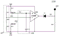
The selective audio amplification function of the head-mounted voice call apparatus 100 will now be described with reference to fig. 4 to 6. Fig. 4 illustrates an exemplary circuit diagram of an audio amplifier switch of the voice headset of fig. 1, fig. 5 illustrates an exemplary circuit diagram of an audio amplifier and a signal adjusting module of the voice headset of fig. 1, and fig. 6 illustrates an exemplary circuit diagram of an amplifier control module of the voice headset of fig. 1.
As shown in fig. 4 and 5, in this embodiment, audio amplifier switch 1311 is a double pole double throw push button switch having 6 terminals 1-6, where terminals 1 and 6 are common, terminal 1 may selectively turn on terminal 5 or terminal 3, and terminal 6 may selectively turn on terminal 2 or terminal 4. Signals from 1331(3) of external audio interface 1331 (connected to the audio output ground of the second audio device) are coupled through C2 capacitor block to input terminal 5. In addition, a signal from 1331(2) (connected to the right channel audio output of the second audio device) of the external audio interface 1331 is input to the terminal 2 via the C1 capacitor blocking direct coupling. Meanwhile, the terminal 2 and the terminal 5 are connected to the two input terminals 401 and 402 of the signal adjustment module 1315. The positive output terminal 403 and the negative output terminal 404 of the audio amplifier 1314 are connected to the terminal 4 and the terminal 3, respectively. A signal line 1024(1) of the cable 1024 connects the terminal 6 to the positive audio input terminal of the second bone conduction vibrator 12 ', and a cable 1024(2) connects the terminal 1 to the negative audio input terminal of the second bone conduction vibrator 12'.
Thus, when terminal 1 is connected to terminal 3 and terminal 6 is connected to terminal 4, audio amplifier switch 1311 is in a first position, electrically coupling positive output 403 and negative output 404 of audio amplifier 1314 to second bone conduction element 12 ', and outputting the amplified second audio signal from the second audio device to second bone conduction element 12'. When terminal 1 is connected to terminal 5 and terminal 6 is connected to terminal 2, audio amplifier switch 1311 is in a second position, electrically coupling the audio output of the second audio device to the second bone conduction element 12 ', outputting a second audio signal from the second audio device coupled via the C1 capacitor and the C2 capacitor to the second bone conduction element 12'.
With continued reference to fig. 4 and 5, the positive input 401 and the negative input 402 of the signal conditioning module 1315 are coupled to terminal 2 and terminal 5, respectively, of the audio amplifier switch 1311, and thus the signal conditioning module 1315 receives a second audio signal from a second audio device. The output terminal of the signal adjusting module 1315 is connected to two input terminals of the audio amplifier 1314. The signal adjustment module 1315 compensates for a low frequency signal in the second audio signal before the second audio signal is amplified when the audio amplifier switch 1311 is in the first position. In this embodiment, the signal adjusting module 1315 is an EQ adjusting circuit (equalization adjusting circuit), which adopts a structure of a low-pass filter and an adder to perform EQ adjustment on the second audio signal from the second audio device, so as to compensate for a low-frequency signal lost by the bone conduction vibrator during bone conduction of the audio signal, thereby improving sound quality. In other embodiments, the signal conditioning module may be other circuitry for processing the audio signal or may be omitted.
In the present embodiment, the audio amplifier 1314 employs an Automatic Gain Control (AGC) amplifier chip, model NS4145, manufactured by shenzhen nawei technologies ltd. In other embodiments, any other type or model of amplifier chip may be used. The audio amplifier 1314 having an Automatic Gain Control (AGC) function may automatically adjust a gain according to the level size of the input adjusted second audio signal. When overload peak clipping distortion is detected to occur due to the second audio signal being excessively amplified, the amplifier chip automatically reduces the gain to reduce the distortion, thereby realizing loud and clear audio amplification. However, in other embodiments, other types of amplifier chips or circuits may be employed.
In addition, the control terminal 405 of the audio amplifier 1314 is controlled by the amplifier control module shown in fig. 6. The amplifier control module 1316 activates the audio amplifier 1314 when the audio amplifier switch 1311 is in the first position to cause the audio amplifier 1314 to amplify a second audio signal from a second audio device. The amplifier control module 1316 deactivates the audio amplifier 1314 when the audio amplifier switch 1311 is in the second position, causing the audio amplifier 1314 to be in a non-operational state.
In the present embodiment, in the amplifier control module 1316, the reference voltage provided by the divided voltage reference detection circuit 407 is provided to the negative input terminal of the voltage comparator 406, the input terminal of the RC low-pass filter 408 is connected to the input terminal 401 of the signal adjusting module 1315, and the low-pass filtered audio signal is provided to the positive input terminal of the voltage comparator 406. The input terminal 402 of the signal conditioning module 1315 is connected to the resistor R11 and then to ground. The voltage comparator 406 outputs a high level when the voltage of the output signal of the RC low-pass filter 408 is greater than the reference voltage provided by the divided reference detection circuit 407, and the voltage comparator 406 outputs a low level when the voltage of the output signal of the RC low-pass filter 408 is less than the reference voltage provided by the divided reference detection circuit 407. The output level of the voltage comparator 406 is divided by a D1 voltage regulator (such as a zener diode or a reference voltage source) and resistors R30 and R31 and then provided to the control terminal 405. In other embodiments, other forms of amplifier control modules may be used, as long as they control the activation of audio amplifier 1314 and enter AGC conditions and deactivate. In the present embodiment, voltage comparator 406 employs a model TLV3491aid bvr voltage comparator chip manufactured by Texas Instruments, usa. In other embodiments, any other type of voltage comparator chip may be used.
The process of the amplifier control module 1316 automatically activating/deactivating the audio amplifier 1314 in the present embodiment is explained with reference to fig. 4-6 as well.
When it is desired to amplify the second audio signal, the audio amplifier switch 1311 is in the first position, i.e., terminal 1 is connected to terminal 3 and terminal 6 is connected to terminal 4. Only the capacitor C13 is connected between the input terminals 401 and 402 of the signal conditioning module 1315, and both terminals are isolated by C1, C2, C17 and C18, so the dc resistance between the input terminals 401 and 402 of the signal conditioning module 1315 approaches infinity. Accordingly, the voltage of the output signal of the RC low pass filter 408 approaches the power supply voltage VDD, and the voltage comparator 406 outputs a high level and provides the high level to the control terminal 405 of the audio amplifier 1314 after voltage division, so as to activate the audio amplifier 1314 to amplify the second audio signal.
When there is no need to amplify the second audio signal, the audio amplifier switch 1311 is in the second position, i.e., terminal 1 turns on terminal 5 and terminal 6 turns on terminal 2. A second bone conduction element 12 'is connected between the input terminals 401 and 402 of the signal conditioning module 1315, and the second bone conduction element 12' has a smaller dc resistance (e.g. 5 Ω), i.e. the dc resistance between the input terminals 401 and 402 of the signal conditioning module 1315 is smaller. Accordingly, the voltage of the output signal of the RC low pass filter 408 is smaller than the reference voltage provided by the voltage division reference detection circuit 407, and the voltage comparator 406 outputs a low level, and the low level is divided and provided to the control terminal 405 of the audio amplifier 1314, so as to deactivate the audio amplifier 1314, and enable the audio amplifier 1314 to be in a non-operating state, that is, enable the second bone conduction vibrator 12' to be in a passive and passive operating state to save power.
The operation of the modules of fig. 4-6 is further described below by taking as an example three different second audio devices shown in fig. 3.
When the second audio device connected to the external audio interface 1331 is the mobile phone 31 or the bluetooth adapter 16, the second audio signal is a normal stereo headphone audio signal, and its output power is low and is not enough to directly drive the second bone conduction element 12', so that the second audio signal needs to be amplified. The user presses the audio amplifier switch 1311 to assume a first position. As described above, the positive output terminal 403 and the negative output terminal 404 of the audio amplifier 1314 are connected to the terminal 4 and the terminal 3, respectively. At this time, after the signals (i.e., the second audio signal output from the mobile phone 31 or the bluetooth adapter 16) from the pins 1331(2) and 1331(3) of the external audio interface 1331 are respectively and directly coupled through the capacitors C1 and C2, the input signals are input to the input terminals 401 and 402 of the signal adjusting module 1315, and EQ adjustment is performed. Meanwhile, as described above, the voltage comparator 406 outputs a high level and is provided to the control terminal 405 of the audio amplifier 1314, thereby activating the audio amplifier 1314 to amplify the second audio signal. The dynamic amplification gain for the second audio signal may be set between 5-40 dB. The positive output terminal 403 and the negative output terminal 404 of the audio amplifier 1314 input the amplified second audio signal to the terminal 4 and the terminal 3 of the audio amplifier switch 1311, and output through the second bone conduction vibrator 12' via the cable 1024 connected to the terminal 6 and the terminal 1.
When the second audio device connected to the external audio interface 1331 is another interphone 32, the second audio signal is a mono audio signal, and the output power thereof is high enough to drive the second bone conduction vibrator 12', so that amplification of the second audio signal is not required. The user presses the audio amplifier switch 1311 to assume the second position. Signals from pins 1331(2) and 1331(3) of the external audio interface 1331 are input to the terminal 2 and the terminal 5 of the audio amplifier switch 1311 after being blocked and directly coupled by the capacitors C1 and C2, respectively, and output through the second bone conduction element 12' via the cable 1024 connected to the terminal 6 and the terminal 1. Meanwhile, the voltage comparator 406 in the amplifier control module 1316 outputs a low level, and provides the low level to the control terminal 405 of the audio amplifier 1314 after voltage division, so as to deactivate the audio amplifier 1314, and make the audio amplifier 1314 in a non-operating state to save power.
By including the audio amplifier switch 1311, the audio amplifier 1314, the signal adjusting module 1315 and the amplifier control module 1316 in the control unit 131, the problem that the interphone PTT earphone is incompatible or universal with a 3.5mm earphone of a common digital product is solved.
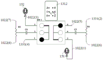
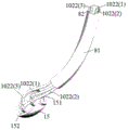
The audio forwarding function of the head-mounted voice call apparatus 100 will now be described with reference to fig. 1 to 2 and fig. 7 to 8. Fig. 7 shows an exemplary circuit diagram of an audio relay switch of the head-mounted voice call apparatus of fig. 1, and fig. 8 shows an exemplary block diagram of a microphone mounting manner of the head-mounted voice call apparatus of fig. 1.
As shown in fig. 7, in this embodiment, audio relay switch 1312 is also a double pole double throw push button switch. Like the audio amplifier switch 1311, it has 6 terminals 1-6, where terminals 1 and 6 are common, terminal 1 may selectively turn on terminal 5 or terminal 3, and terminal 6 may selectively turn on terminal 2 or terminal 4. As shown in fig. 1, 2 and 8, the microphone assembly 15 includes two microphones (e.g., electret microphones): a first microphone 151 and a second microphone 152. The first microphone 151 is connected to the signal lines 1022(1) and 1022(2), and the second microphone 152 is connected to the signal lines 1022(3) and 1022 (2). The first microphone 151 and the second microphone 152 share one ground signal line 1022 (2). The suspension microphone tube 81 is sleeved outside the signal lines 1022(1), 1022(2), and 1022(3), and one end of the suspension microphone tube 81 is installed below the first bone conduction vibrator 12. The suspension microphone hose 81 is a hollow deformable hose, for example, a metal corrugated hose.
Referring back to fig. 7, first microphone 151 is connected to terminal 2 of audio relay switch 1312 by signal line 1022(1), and second microphone 152 is connected to terminal 5 of audio relay switch 1312 by signal line 1022 (3). The signal line 1022(7) is connected to one end of the potentiometer R3, and the other end of the potentiometer R3 is connected to the signal line 1022(6) (which is connected to the interphone audio input ground). The potentiometer R3 is used to attenuate the audio signal from the intercom 11 and is input to the terminal 3 through the capacitor C4. The pin 1331(2) of the external audio interface 1331 is connected to one end of the potentiometer R4 through the internal audio jack 1313, and the other end of the potentiometer R4 is connected to the signal line 1022 (6). The potentiometer R4 is used to attenuate the right channel audio signal from the second audio device and is input to terminal 4 through capacitor C5. Pins 1331(4) of external audio interface 1331 (which are connected to the audio input of the second audio device) are connected to terminal 1 via internal audio jack 1313, and signal line 1022(5) (which is connected to the speaker audio input positive) is connected to terminal 6.
In the normal mode, terminal 1 of audio relay switch 1312 turns on terminal 5 and terminal 6 turns on terminal 2, and audio relay switch 1312 is in the first position. The first microphone 151 is electrically coupled to the audio input of the intercom 11 via signal lines 1022(1) and 1022(5), and the second microphone 152 is electrically coupled to the audio input of the second audio device via signal line 1022(3) and pins 1331 (4). Thus, the audio signal from the first microphone 151 is transmitted to the audio input of the intercom 11 connected to the signal line 1022(5), and the audio signal from the second microphone 152 is transmitted to the audio input of the second audio device connected to the pin 1331 (4). In this mode, the first microphone 151 functions as an audio input device of the interphone 11, and the second microphone 152 functions as an audio input device of the second audio device.
In relay mode, terminal 1 of audio relay switch 1312 turns on terminal 3 and terminal 6 turns on terminal 4, with audio relay switch 1312 in the second position. The audio output of the intercom 11 is electrically coupled to the audio input of the second audio device via signal lines 1022(7) and pins 1331(4), and the audio output of the second audio device is electrically coupled to the audio input of the intercom 11 via pins 1331(2) and signal lines 1022 (5). In this mode, the audio signals output by the intercom 11 and the second audio device enter the audio input end of the other party after being respectively attenuated, and the C4 capacitor and the C5 capacitor are isolated and coupled, so that the cross interconnection of the audio signals is realized, an audio relay is formed, and the user can monitor the communication contents of the two devices at the same time.
In some embodiments, two or more head-mounted voice communicators may also be used to enable relaying between multiple audio devices. For example, a first mobile phone connected to a first head-mounted voice communicator relays with a first interphone on the first head-mounted voice communicator, which in turn performs radio transmission with a second interphone on a second head-mounted voice communicator, and the second interphone relays with a second mobile phone connected to the second head-mounted voice communicator, and finally a radio voice signal transmission channel is established between the first mobile phone and the second mobile phone.
By including an audio forwarding switch in the control unit, relays can be temporarily set up between different interphones or between an interphone and other digital products (such as mobile phones), for example, voice calls are realized without public mobile (cellular) communication networks (such as in the field).
In some embodiments, a mobile phone or a computer pre-installed with audio encoding-decoding software commonly used in amateur radio, such as SSTV, EasyPal, multispsk, RTTY, etc., may use a first intercom fixed on a head-mounted voice communicator and another intercom + mobile phone or computer assembly pre-installed with the above software to implement a low-rate radio transmission function of image fax and binary data based on intercom channels. The low-rate transmission mode of the image fax and the binary data does not need to use a WIFI, a Bluetooth and a public frequency band of a public mobile (cellular) communication network, and a user can set parameters such as communication frequency, frequency hopping, subsonic and coding modes on two interphones, so that the image fax and binary data transmission mode has high confidentiality, anti-interference performance and survivability. This can provide the secure, free communication guarantee of local communication for the user under the harsh electromagnetic environment.
With continued reference to fig. 8, in the present embodiment, the headset 100 further includes a radio frequency ground wire 82, the upper end of which is connected to the ground terminal (e.g., the aluminum heat sink plate, the GND plane of the circuit board or the battery cathode GND) of the intercom 11, and is disposed in the hanging microphone hose in parallel with the signal wires 1022(1), 1022(2), and 1022 (3). In the present embodiment, the rf ground line 82 may be a wire (preferably, an enameled copper wire with a diameter of 0.6mm and a length of 13 cm) with a diameter of 0.1-2mm and a length of 1-50cm, which is combined with the circuit board of the interphone 11 with a length of 7-10cm to achieve a physical size of about 8-60cm, and the resonance size of about 1/4 wavelength can be adjusted in the common operating frequency bands 136 and 470MHz of the interphone 11.
Through setting up the radio frequency earth connection, still prolonged the earth mat of intercom when reducing microphone common mode interference, also increased whole antenna feed system's physical dimension promptly, tested on the spot through the antenna analysis appearance, this kind of technological improvement can reduce intercom antenna feed system's Voltage Standing Wave Ratio (VSWR), finely tunes resonant frequency, improves intercom antenna feed system's transmitting efficiency and work bandwidth. The implementation effect of the present disclosure proves its benefits.
Referring back to fig. 1, the head-mounted voice communicator 100 further includes a ferrite ring 17 disposed on the semi-annular frame 102 between the first bone conduction vibrator 12 and the first battery box 14. The ferrite ring 17 is a hollow magnetic material made of ferrite material. Since the cable wires and the steel wire conductive material are accommodated in the semi-annular frame 102 and an approximately semicircular space structure is formed, a short-circuit condition is provided for a vortex electric field, and thus a large induced current is generated in the semi-annular frame 102. Meanwhile, the semicircular structure can participate in the antenna feeding process to form an upward transmission side lobe, so that the transmission gain of the antenna in the horizontal direction is reduced and the SAR value of a human body is increased. The ferrite magnetic ring 17 is sleeved on the semi-annular frame 102 containing the cable and has the filtering characteristic of low-pass resistance and high-frequency resistance, the radio-frequency resistance of the semi-annular frame 102 is increased, the short-circuit condition and the feeding process of a vortex electric field are damaged, the dissipation of electromagnetic wave energy side lobe emission and the increase of a human body SAR value are avoided, the horizontal emission gain of the antenna is basically not influenced, and the interference of radio-frequency current on a microphone audio signal is eliminated.
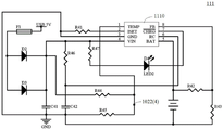
Next, a charging module of the interphone 11 is explained with reference to fig. 1 to 2 and 9, and fig. 9 shows an exemplary circuit diagram of the charging module of the interphone in fig. 1. As shown in fig. 1 and 2, the back surface of the intercom 11 is connected with the first bone conduction vibrator 12, and a charging module 111 (e.g., a PCB circuit board) is accommodated in the body of the intercom 11. The interphone 11 is provided with a USB interface (such as a USB TYPE-C interface or a USB Micro-B interface) to provide a USB 5V power supply to the charging module 111 via the USB interface and charge the AA-sized rechargeable batteries in the first battery box 14 and the second battery box 14'.
In the circuit diagram shown in fig. 9, F1 is a self-recovery fuse, and the parallel diodes D2 and D3 and the capacitor C41 are used to reduce power supply ripple, absorb surge pulse, and prevent accidents such as short circuit, power supply reverse polarity and backflow. Resistor R41 sets the maximum charging current for the charge management chip 1110. In the present embodiment, the charge management chip 1110 is a nickel hydride charge management chip with model number CN3085, manufactured by shanghai, e.g., yun electronics ltd. In other embodiments, any other model of charge management chip may be used. Resistor R46 forms an RC time delayed freewheeling charge with capacitor C42. The resistors R42 and R43 form a voltage divider to determine the charge saturation voltage. The resistors R42 and R43 are connected at one end and at the other end to two power lines of the cable 1022, respectively, to supply power to the intercom 11. The resistors R44 and R45 are connected to a signal line 1022(4) (which is connected to a thermistor, such as a negative temperature coefficient thermistor, in the second battery pack 14 ') for sensing the charging temperature in the second battery pack 14' to between 0-40 c. The resistor R47 is connected to the led D2 for indicating the charging state.
A pair of cushion members 18 and 18' of the head-mounted voice communicator will be described next with reference to fig. 1-2 and fig. 10(a) - (c). Fig. 10(a) and (b) show two angled side views of the first cushion assembly 18, respectively. As shown in fig. 10(a) and (b), the first cushion assembly 18 includes a first catch 181, a first support tray 182 and a first gel 183. The first card slot 181 is adapted to receive the first bone conduction element 12, is dimensioned to be slightly larger than the outer dimensions of the first bone conduction element 12, and is shaped to match the first bone conduction element 12 to form a nested transition fit with the first bone conduction element 12.
A hollow first support tray 182 is fixedly connected to the first catch 181 and is used to define the form of the first gel 183. Specifically, the first support tray 182 is a ring of hollow thin-walled continuous body, the inner wall is a smooth hollow shape, and the edge position of the outer wall is provided with at least two fold ring-like groove structures for coating glue to stick the plastic film to fix the edge of the first gel 183, so that the first gel 183 is limited in the first support tray 182. The first support tray 182 may be made of thermoplastic or metal and the first gel 183 may be a resilient polymer material such as silicone gel, D30 gel or aqueous gel. When the first bone conduction element 12 is received in the first card slot 181, the first bone conduction element 12 is in direct contact with the first gel 183. In this embodiment, a small amount of glue or a conductive metal film with double-sided tape is applied to the back of the first gel 183 to bond the first gel 183 and the first bone conduction vibrator 12 together, so as to fill the gap between the first gel 183 and the first bone conduction vibrator 12 and improve the sound transmission efficiency.
In fig. 10(a) and (b), the first card slot 181 is further provided with a pair of card holes 184 and 184', and correspondingly, a pair of fasteners are provided at corresponding positions on the back surface of the intercom 11. When the intercom 11 and the first cushion member 18, which have been fixedly connected to the first bone conduction vibrator 12, are mounted, the first bone conduction vibrator 12 is received in the first card slot 181, and the pair of snaps on the intercom 11 are engaged with the pair of snap holes 184 and 184' on the first card slot 181, thereby further enhancing the strength of the mechanical connection between the first bone conduction vibrator 12 and the first cushion member 18. In other embodiments, the first card slot 181 and the first bone conduction vibrator 12 can be bonded together by glue or hot melting to increase the mechanical connection strength.
Similarly, fig. 10(c) shows a side view of the second cushion assembly 18'. The second cushion assembly 18 'includes a second catch 181', a second support tray 182 ', and a second gel 183'. The second card slot 181 ' is adapted to receive a second bone conduction element 12 ', which is dimensioned slightly larger than the outer dimensions of the second bone conduction element 12 ', and which is shaped to match the second bone conduction element 12 ' to form a nested transition fit with the second bone conduction element 12 '.
The second support tray 182 ' is fixedly connected to the second engaging groove 181 ' and is used to define the shape of the second gel 183 '. The structure of the second card slot 181 ' and the second support tray 182 ', and the manner of mounting the second gel 183 ' and the second bone conduction element 12 ' are similar to the first cushion assembly 18 ', and therefore will not be described in detail. In this embodiment, the second card slot 181 'and the second bone conduction vibrator 12' are bonded together by glue or hot melt.
Through set up the cushion subassembly on the bone conduction oscillator, can disperse the pressure that the semicircular frame produced and hold the power to reduce the pressure to skin through the contact of soft gel and human skin, increase the long-term comfort level of wearing of bone conduction oscillator, reduce the risk of pressing the sore. In addition, the contact area with the skin of the human body is increased, so that the pressure on the skin soft tissue can be further reduced. In addition, the density of the gel is similar to that of human soft tissue, and the gel has good acoustic and vibration transmission performance and is beneficial to transmitting the vibration energy emitted by the bone conduction vibrator. In addition, the cushion assembly is located between the interphone and the human body, the distance between the antenna and the head is increased, a good capacitive coupling condition is formed, the SAR value of the human body is reduced, meanwhile, the human body is fully utilized as a ground net part of the antenna feed system to participate in feeding, and the receiving and sending efficiency of the antenna system is further improved. The groove structure arranged at the edge of the supporting tray can ensure that the gel is firmly attached to the groove structure, and a structure similar to a cone loudspeaker can be formed, so that the efficiency of transmitting vibration energy can be improved.
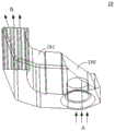
The deflector prism 19 of the head-mounted voice call apparatus 100 of the present disclosure will now be described with reference to fig. 1 and fig. 11(a) - (b). Fig. 11(a) - (b) show two examples of a polarization prism mounted on the intercom of fig. 1, respectively. As shown in fig. 1, a deflector prism 19 is installed at the top of the interphone 11 for guiding light emitted from an illumination device (e.g., an illumination lamp) at the top of the interphone 11 to the front of the user. As shown in fig. 11(a), the deflection prism 19 includes a deflection section 190 and a light guide strip 191. The deflecting portion 190 has a 45-degree slope for deflecting vertical light incident from the a direction (i.e., light emitted by an illumination lamp installed at the top of the interphone 11) into horizontal light. The light guide strip 191 is arc-shaped and guides the deflected horizontal light to the direction B to be emitted. The profile of the light guide strip 191 may be a smooth arc and/or a combination of planar corners. In the present embodiment, the deflector prism 19 is made of transparent resin or glass, and its refractive index is greater than 1.414. Fig. 11(b) shows another example of a partial prism 19', which is different from the partial prism 19 in its shape and direction of guiding light. The deflector prisms of different shapes can be arranged according to specific needs, as long as the deflector prisms can deflect the light of the illuminating lamp on the interphone 11 to a proper direction.
By arranging the deflector prism at the top of the interphone, when the interphone antenna is in a vertical polarization working condition (namely the working condition with the maximum communication coverage range), light rays of the illuminating lamp can horizontally shoot to the front of a user. The technical improvement reduces the communication coverage by eliminating the need for the interphone to be converted to a horizontal polarization state when the interphone uses the lighting function. Therefore, the present embodiment can avoid the mutual exclusivity of the illumination function and the communication function, which can be used simultaneously.
The head-wearing voice communication device can enable the audio signal of first audio equipment (such as an interphone) installed on the head-wearing frame to be output through the first bone conduction vibrator, and can be externally connected with second audio equipment (such as a mobile phone) to enable the audio signal of the first audio equipment to be output through the second bone conduction vibrator, and the two paths of signals are independent. Thus, the present disclosure takes full advantage of the ability of the human left and right ears to simultaneously receive and distinguish audio signals from both devices, while maintaining alertness for ambient sounds, eliminating safety hazards and reducing interference with the ambient environment.
The above description is only an alternative embodiment of the present disclosure and is not intended to limit the embodiment of the present disclosure, and various modifications and changes may be made to the embodiment of the present disclosure by those skilled in the art. Any modification, equivalent replacement, improvement, etc. made within the spirit and principle of the embodiments of the present disclosure should be included in the scope of protection of the embodiments of the present disclosure.
While embodiments of the present disclosure have been described with reference to several particular embodiments, it should be understood that embodiments of the present disclosure are not limited to the particular embodiments disclosed. The embodiments of the disclosure are intended to cover various modifications and equivalent arrangements included within the spirit and scope of the appended claims. The scope of the claims is to be accorded the broadest interpretation so as to encompass all such modifications and equivalent structures and functions.
Finally, as medical health care workers and international amateur Radio (also called HAM Radio), for the phenomenon that digital standards such as DMR, dPMR, C4FM, D-STAR, TETRA, PDT and the like are incompatible with each other, which is caused by the digital development of analog interphones in recent years (see eleven chapters of "old york | century"), the relay function disclosed by the invention can be used for realizing interconnection and intercommunication so as to eliminate the digital huge gully of each battle (see science fiction television, "interstellar maze" -universal translator of universe and EPS relay). This helps the user to use the head-mounted voice call apparatus safely and freely. De BH4CAZ & KD9EZG VY-73.
Claims (13)
1. A head-mounted voice communicator comprising:
a head-mounted frame;
the first audio equipment is arranged on the head-mounted frame and is fixedly connected with the head-mounted frame;
the first bone conduction vibrator and the second bone conduction vibrator are respectively arranged on the head-wearing type frame and are fixedly connected with the head-wearing type frame; and
a control unit disposed on the head-mounted frame and electrically coupled with the first audio device, the first bone-conduction transducer, the second bone-conduction transducer, and a second audio device, wherein the control unit is configured to:
receiving a first audio signal from the first audio device and outputting via the first bone conduction vibrator; and
a second audio signal from the second audio device is received and output via the second bone conduction element.
2. The apparatus of claim 1, wherein the control unit further comprises:
an audio amplifier electrically coupled with an audio output of the second audio device to selectively amplify the second audio signal; and
an audio amplifier switch configured to:
when the second audio signal is at the first position, the second audio signal is amplified by the audio amplifier and then output through the second bone conduction vibrator; and
when in the second position, causing the second audio signal to be output directly via the second bone conduction element.
3. The apparatus of claim 2, wherein the control unit further comprises an amplifier control module configured to:
activating the audio amplifier to amplify the second audio signal when the audio amplifier switch is in the first position; and
deactivating the audio amplifier when the audio amplifier switch is in the second position.
4. The method of claim 2, wherein the control unit further comprises a signal conditioning module electrically coupled with an audio output of the second audio device and configured to compensate for low frequency signals in the second audio signal before the second audio signal is amplified when the audio amplifier switch is in the first position.
5. The apparatus of claim 1, further comprising first and second microphones fixedly connected to the head-mounted frame, respectively, and electrically coupled with the control unit for inputting audio signals to audio inputs of the first and second audio devices, respectively.
6. The apparatus of claim 5, wherein the control unit further comprises an audio forwarding switch configured to:
when in a first position, electrically coupling the first microphone with an audio input of the first audio device and electrically coupling the second microphone with an audio input of the second audio device; and is
When in a second position, electrically coupling the audio output of the first audio device with the audio input of the second audio device and electrically coupling the audio output of the second audio device with the audio input of the first audio device.
7. The apparatus of claim 1, wherein the first microphone and the second microphone are electrically coupled with the control unit via a cable cord, and further comprising a radio frequency ground cord electrically coupled with a ground terminal of the first audio device, the radio frequency ground cord being disposed in parallel with the cable cord.
8. The apparatus of claim 1, further comprising at least one rechargeable battery for powering the first audio device and the control unit, wherein the first audio device comprises a charging module configured to control charging of the at least one rechargeable battery.
9. The apparatus of claim 1, wherein the first audio device is an intercom and the second audio device is any one of a mobile phone, an intercom, or a bluetooth adapter.
10. The apparatus of claim 1, wherein the head-mounted frame comprises a top head weight bearing band and a hollow semi-ring frame, wherein the control unit is electrically coupled with the first audio device, the first bone conduction vibrator, the second bone conduction vibrator, and the second audio device via a cable housed within the semi-ring frame, and further comprising a ferrite ring sleeved over the semi-ring frame.
11. The apparatus of claim 1, further comprising a pair of cushion assemblies, each cushion assembly comprising a card slot for receiving the first or second bone conduction vibrator, a hollow support tray fixedly connected with the card slot for receiving the gel, and a gel, wherein the gel is in direct contact with the first or second bone conduction vibrator when the first or second bone conduction vibrator is received in the card slot.
12. The apparatus of claim 1, further comprising a deflector prism and the first audio device comprises an illumination device, wherein the deflector prism is configured to receive and deflect light emitted by the illumination device.
13. The apparatus of claim 1, wherein the second audio device is removably connected to the head-mounted voice communicator.
Priority Applications (2)
| Application Number | Priority Date | Filing Date | Title |
|---|---|---|---|
| CN202010557805.1A CN113825054B (en) | 2020-06-18 | 2020-06-18 | Head-wearing voice communication device |
| PCT/CN2020/112794 WO2021253644A1 (en) | 2020-06-18 | 2020-09-01 | Head worn-type voice communication apparatus |
Applications Claiming Priority (1)
| Application Number | Priority Date | Filing Date | Title |
|---|---|---|---|
| CN202010557805.1A CN113825054B (en) | 2020-06-18 | 2020-06-18 | Head-wearing voice communication device |
Publications (2)
| Publication Number | Publication Date |
|---|---|
| CN113825054A true CN113825054A (en) | 2021-12-21 |
| CN113825054B CN113825054B (en) | 2024-01-12 |
Family
ID=78924433
Family Applications (1)
| Application Number | Title | Priority Date | Filing Date |
|---|---|---|---|
| CN202010557805.1A Active CN113825054B (en) | 2020-06-18 | 2020-06-18 | Head-wearing voice communication device |
Country Status (2)
| Country | Link |
|---|---|
| CN (1) | CN113825054B (en) |
| WO (1) | WO2021253644A1 (en) |
Citations (17)
| Publication number | Priority date | Publication date | Assignee | Title |
|---|---|---|---|---|
| JPH0715688A (en) * | 1993-06-29 | 1995-01-17 | Toshiba Corp | Audio signal processing circuit |
| CN2379986Y (en) * | 1998-06-02 | 2000-05-24 | 天津开发区朗达电子声像技术有限公司 | Remote control voic box/power amplifier selector |
| CN1304215A (en) * | 2000-01-07 | 2001-07-18 | 摩托罗拉公司 | Method and device for operating single track and stereophony of radio receiver |
| US6748085B1 (en) * | 1998-05-06 | 2004-06-08 | Samsung Electronics Co., Ltd. | Computer system with a common audio input for its audio circuitry |
| CN2650430Y (en) * | 2003-11-04 | 2004-10-20 | 周纬 | Head intercom for electrician |
| US20080292120A1 (en) * | 2007-05-25 | 2008-11-27 | Wilson Kelce S | Automatically reconfigurable stereo speaker system |
| KR20110084581A (en) * | 2010-01-18 | 2011-07-26 | 이동원 | Microphone of bone conduction |
| CN202406265U (en) * | 2011-12-16 | 2012-08-29 | 江辉 | Combined type bone-conduction earphone |
| US20120243691A1 (en) * | 2008-05-09 | 2012-09-27 | Sure Best Limited | Wireless headset device capable of providing balanced stereo and method thereof |
| CN203554660U (en) * | 2013-10-31 | 2014-04-16 | 南京正泽科技有限公司 | Digital voice control bone conduction headset |
| US20140146243A1 (en) * | 2012-11-28 | 2014-05-29 | Lenovo (Beijing) Co., Ltd. | Head-Mounted Electronic Device And Audio Processing Method |
| CN204425599U (en) * | 2015-03-19 | 2015-06-24 | 四川中软科技有限公司 | A kind of earphone based on bone conduction technology |
| CN106658304A (en) * | 2017-01-11 | 2017-05-10 | 广东小天才科技有限公司 | Wearable device and audio output control method used for same |
| CN206442490U (en) * | 2016-12-27 | 2017-08-25 | 深圳市八达晟电子有限公司 | Osteoacusis gaming headset |
| KR101773357B1 (en) * | 2016-02-24 | 2017-08-31 | 주식회사 아미스 | Walkie-talkie of headphone using for bone conduction speaker |
| CN208112881U (en) * | 2018-04-03 | 2018-11-16 | 深圳市增长点科技有限公司 | A kind of novel bone conduction earphone |
| CN109863758A (en) * | 2016-10-28 | 2019-06-07 | 松下知识产权经营株式会社 | Bone-conduction head set type ear receiver |
Family Cites Families (3)
| Publication number | Priority date | Publication date | Assignee | Title |
|---|---|---|---|---|
| US9124974B2 (en) * | 2013-06-17 | 2015-09-01 | Michael Flynn | Hat mounted music system |
| CN205545930U (en) * | 2016-02-03 | 2016-08-31 | 褚建峰 | Bone conductive hearing -aid |
| CN206442477U (en) * | 2017-01-20 | 2017-08-25 | 昆明聚讯科技有限公司 | Wide area communications sytem based on mobile radio communication network modem and digital handset |
-
2020
- 2020-06-18 CN CN202010557805.1A patent/CN113825054B/en active Active
- 2020-09-01 WO PCT/CN2020/112794 patent/WO2021253644A1/en active Application Filing
Patent Citations (17)
| Publication number | Priority date | Publication date | Assignee | Title |
|---|---|---|---|---|
| JPH0715688A (en) * | 1993-06-29 | 1995-01-17 | Toshiba Corp | Audio signal processing circuit |
| US6748085B1 (en) * | 1998-05-06 | 2004-06-08 | Samsung Electronics Co., Ltd. | Computer system with a common audio input for its audio circuitry |
| CN2379986Y (en) * | 1998-06-02 | 2000-05-24 | 天津开发区朗达电子声像技术有限公司 | Remote control voic box/power amplifier selector |
| CN1304215A (en) * | 2000-01-07 | 2001-07-18 | 摩托罗拉公司 | Method and device for operating single track and stereophony of radio receiver |
| CN2650430Y (en) * | 2003-11-04 | 2004-10-20 | 周纬 | Head intercom for electrician |
| US20080292120A1 (en) * | 2007-05-25 | 2008-11-27 | Wilson Kelce S | Automatically reconfigurable stereo speaker system |
| US20120243691A1 (en) * | 2008-05-09 | 2012-09-27 | Sure Best Limited | Wireless headset device capable of providing balanced stereo and method thereof |
| KR20110084581A (en) * | 2010-01-18 | 2011-07-26 | 이동원 | Microphone of bone conduction |
| CN202406265U (en) * | 2011-12-16 | 2012-08-29 | 江辉 | Combined type bone-conduction earphone |
| US20140146243A1 (en) * | 2012-11-28 | 2014-05-29 | Lenovo (Beijing) Co., Ltd. | Head-Mounted Electronic Device And Audio Processing Method |
| CN203554660U (en) * | 2013-10-31 | 2014-04-16 | 南京正泽科技有限公司 | Digital voice control bone conduction headset |
| CN204425599U (en) * | 2015-03-19 | 2015-06-24 | 四川中软科技有限公司 | A kind of earphone based on bone conduction technology |
| KR101773357B1 (en) * | 2016-02-24 | 2017-08-31 | 주식회사 아미스 | Walkie-talkie of headphone using for bone conduction speaker |
| CN109863758A (en) * | 2016-10-28 | 2019-06-07 | 松下知识产权经营株式会社 | Bone-conduction head set type ear receiver |
| CN206442490U (en) * | 2016-12-27 | 2017-08-25 | 深圳市八达晟电子有限公司 | Osteoacusis gaming headset |
| CN106658304A (en) * | 2017-01-11 | 2017-05-10 | 广东小天才科技有限公司 | Wearable device and audio output control method used for same |
| CN208112881U (en) * | 2018-04-03 | 2018-11-16 | 深圳市增长点科技有限公司 | A kind of novel bone conduction earphone |
Also Published As
| Publication number | Publication date |
|---|---|
| WO2021253644A1 (en) | 2021-12-23 |
| CN113825054B (en) | 2024-01-12 |
Similar Documents
| Publication | Publication Date | Title |
|---|---|---|
| US7548617B2 (en) | Bluetooth earphone | |
| US6681022B1 (en) | Two-way communication earpiece | |
| US20060126882A1 (en) | Earphone | |
| US20040165720A1 (en) | Two-way voice communication device having external acoustic noise reduction | |
| US20110019860A1 (en) | Communication device with combined electrical socket and microphone opening | |
| CA2483439A1 (en) | Earphone/microphone adapter | |
| CN103125125A (en) | Communication headset | |
| US20160100237A1 (en) | Integrated Personal Electronic Device | |
| US9742890B2 (en) | System for control and operation of electronic devices | |
| CN212649682U (en) | Bluetooth headset capable of being worn after TWS combination | |
| JP3066305U (en) | Hearing aid | |
| CN209994537U (en) | Earphone compatible with 2.4G wireless receiving mode | |
| CN111479191A (en) | Wireless earphone, head-wearing earphone bracket and earphone assembly | |
| CN113825054B (en) | Head-wearing voice communication device | |
| KR20160037183A (en) | Headset | |
| CN213462193U (en) | Magnetic traffic earphone | |
| CN217406705U (en) | Headset, headset device, and removable control module and removable battery pack | |
| CN220210575U (en) | Headset earphone | |
| CN210351555U (en) | Wireless earphone based on anion | |
| CN218473341U (en) | Intelligent Bluetooth earphone | |
| CN210629796U (en) | Hanging neck type Bluetooth earphone | |
| CN218634211U (en) | Multifunctional earphone | |
| CN217116399U (en) | Hearing aid | |
| CN219372567U (en) | Headset | |
| CN219536266U (en) | TWS earphone with waterproof capability |
Legal Events
| Date | Code | Title | Description |
|---|---|---|---|
| PB01 | Publication | ||
| PB01 | Publication | ||
| SE01 | Entry into force of request for substantive examination | ||
| SE01 | Entry into force of request for substantive examination | ||
| GR01 | Patent grant | ||
| GR01 | Patent grant |