CN113727804A - Machining system, machining method, robot system, connecting device, and terminal effector device - Google Patents
Machining system, machining method, robot system, connecting device, and terminal effector device Download PDFInfo
- Publication number
- CN113727804A CN113727804A CN201980095238.8A CN201980095238A CN113727804A CN 113727804 A CN113727804 A CN 113727804A CN 201980095238 A CN201980095238 A CN 201980095238A CN 113727804 A CN113727804 A CN 113727804A
- Authority
- CN
- China
- Prior art keywords
- movable member
- processing
- irradiation device
- processing system
- coating film
- Prior art date
- Legal status (The legal status is an assumption and is not a legal conclusion. Google has not performed a legal analysis and makes no representation as to the accuracy of the status listed.)
- Pending
Links
- 239000012636 effector Substances 0.000 title claims description 123
- 238000003754 machining Methods 0.000 title description 160
- 238000000034 method Methods 0.000 title description 26
- 238000012545 processing Methods 0.000 claims abstract description 655
- 238000005259 measurement Methods 0.000 claims description 227
- 230000008859 change Effects 0.000 claims description 70
- 230000033001 locomotion Effects 0.000 claims description 59
- 238000003672 processing method Methods 0.000 claims description 15
- 230000009467 reduction Effects 0.000 claims description 14
- 230000008878 coupling Effects 0.000 claims description 12
- 238000010168 coupling process Methods 0.000 claims description 12
- 238000005859 coupling reaction Methods 0.000 claims description 12
- 238000005286 illumination Methods 0.000 claims description 12
- 238000003384 imaging method Methods 0.000 claims description 11
- 239000003550 marker Substances 0.000 claims description 11
- 230000005484 gravity Effects 0.000 claims description 10
- 230000002452 interceptive effect Effects 0.000 claims description 6
- 238000006073 displacement reaction Methods 0.000 claims description 3
- 230000011664 signaling Effects 0.000 claims description 3
- 239000011248 coating agent Substances 0.000 description 448
- 238000000576 coating method Methods 0.000 description 448
- 230000003287 optical effect Effects 0.000 description 77
- 230000008093 supporting effect Effects 0.000 description 64
- 238000012360 testing method Methods 0.000 description 50
- 238000005192 partition Methods 0.000 description 43
- 239000007789 gas Substances 0.000 description 38
- 239000000463 material Substances 0.000 description 30
- 230000002829 reductive effect Effects 0.000 description 28
- 230000006870 function Effects 0.000 description 25
- 230000015572 biosynthetic process Effects 0.000 description 23
- 230000008569 process Effects 0.000 description 22
- 239000012530 fluid Substances 0.000 description 20
- 230000001976 improved effect Effects 0.000 description 20
- 239000000126 substance Substances 0.000 description 18
- 238000003860 storage Methods 0.000 description 16
- 239000013256 coordination polymer Substances 0.000 description 14
- 238000010521 absorption reaction Methods 0.000 description 13
- 238000004590 computer program Methods 0.000 description 13
- 230000000694 effects Effects 0.000 description 13
- 238000002955 isolation Methods 0.000 description 13
- 238000001514 detection method Methods 0.000 description 12
- 239000000470 constituent Substances 0.000 description 11
- 238000013016 damping Methods 0.000 description 10
- 210000001364 upper extremity Anatomy 0.000 description 10
- 230000001678 irradiating effect Effects 0.000 description 8
- 239000000049 pigment Substances 0.000 description 8
- -1 acrylic polyol Chemical class 0.000 description 6
- 239000007788 liquid Substances 0.000 description 6
- 239000003973 paint Substances 0.000 description 5
- 238000007789 sealing Methods 0.000 description 5
- 238000004040 coloring Methods 0.000 description 4
- 230000000737 periodic effect Effects 0.000 description 4
- 230000000007 visual effect Effects 0.000 description 4
- 238000002835 absorbance Methods 0.000 description 3
- 230000005540 biological transmission Effects 0.000 description 3
- 230000001965 increasing effect Effects 0.000 description 3
- 230000001939 inductive effect Effects 0.000 description 3
- 230000007246 mechanism Effects 0.000 description 3
- 229920005862 polyol Polymers 0.000 description 3
- 230000002265 prevention Effects 0.000 description 3
- 230000001902 propagating effect Effects 0.000 description 3
- 238000001179 sorption measurement Methods 0.000 description 3
- 230000003595 spectral effect Effects 0.000 description 3
- 229920002554 vinyl polymer Polymers 0.000 description 3
- 240000002853 Nelumbo nucifera Species 0.000 description 2
- 235000006508 Nelumbo nucifera Nutrition 0.000 description 2
- 235000006510 Nelumbo pentapetala Nutrition 0.000 description 2
- 230000001133 acceleration Effects 0.000 description 2
- 230000002238 attenuated effect Effects 0.000 description 2
- 239000004918 carbon fiber reinforced polymer Substances 0.000 description 2
- 238000004140 cleaning Methods 0.000 description 2
- 238000004891 communication Methods 0.000 description 2
- 230000008602 contraction Effects 0.000 description 2
- 238000005520 cutting process Methods 0.000 description 2
- 238000000354 decomposition reaction Methods 0.000 description 2
- 230000006866 deterioration Effects 0.000 description 2
- 238000009826 distribution Methods 0.000 description 2
- 238000001704 evaporation Methods 0.000 description 2
- 230000004438 eyesight Effects 0.000 description 2
- 229910052731 fluorine Inorganic materials 0.000 description 2
- 239000011737 fluorine Substances 0.000 description 2
- 239000011261 inert gas Substances 0.000 description 2
- 239000002184 metal Substances 0.000 description 2
- 238000012986 modification Methods 0.000 description 2
- 230000004048 modification Effects 0.000 description 2
- 230000010355 oscillation Effects 0.000 description 2
- 230000036961 partial effect Effects 0.000 description 2
- 230000002940 repellent Effects 0.000 description 2
- 239000005871 repellent Substances 0.000 description 2
- 229920005989 resin Polymers 0.000 description 2
- 239000011347 resin Substances 0.000 description 2
- 239000004065 semiconductor Substances 0.000 description 2
- 238000001228 spectrum Methods 0.000 description 2
- 125000000391 vinyl group Chemical group [H]C([*])=C([H])[H] 0.000 description 2
- IJGRMHOSHXDMSA-UHFFFAOYSA-N Atomic nitrogen Chemical compound N#N IJGRMHOSHXDMSA-UHFFFAOYSA-N 0.000 description 1
- 241000251730 Chondrichthyes Species 0.000 description 1
- 229910000737 Duralumin Inorganic materials 0.000 description 1
- VGGSQFUCUMXWEO-UHFFFAOYSA-N Ethene Chemical compound C=C VGGSQFUCUMXWEO-UHFFFAOYSA-N 0.000 description 1
- 239000005977 Ethylene Substances 0.000 description 1
- 241000282326 Felis catus Species 0.000 description 1
- YCKRFDGAMUMZLT-UHFFFAOYSA-N Fluorine atom Chemical compound [F] YCKRFDGAMUMZLT-UHFFFAOYSA-N 0.000 description 1
- XUIMIQQOPSSXEZ-UHFFFAOYSA-N Silicon Chemical compound [Si] XUIMIQQOPSSXEZ-UHFFFAOYSA-N 0.000 description 1
- 238000002679 ablation Methods 0.000 description 1
- 230000004308 accommodation Effects 0.000 description 1
- NIXOWILDQLNWCW-UHFFFAOYSA-N acrylic acid group Chemical group C(C=C)(=O)O NIXOWILDQLNWCW-UHFFFAOYSA-N 0.000 description 1
- 229910045601 alloy Inorganic materials 0.000 description 1
- 239000000956 alloy Substances 0.000 description 1
- 230000003373 anti-fouling effect Effects 0.000 description 1
- 230000008901 benefit Effects 0.000 description 1
- 210000000988 bone and bone Anatomy 0.000 description 1
- 238000004364 calculation method Methods 0.000 description 1
- 230000000052 comparative effect Effects 0.000 description 1
- 230000006835 compression Effects 0.000 description 1
- 238000007906 compression Methods 0.000 description 1
- 229910001873 dinitrogen Inorganic materials 0.000 description 1
- 229920001971 elastomer Polymers 0.000 description 1
- 229920006334 epoxy coating Polymers 0.000 description 1
- 239000000835 fiber Substances 0.000 description 1
- 230000004927 fusion Effects 0.000 description 1
- 239000011521 glass Substances 0.000 description 1
- 230000006872 improvement Effects 0.000 description 1
- 238000000608 laser ablation Methods 0.000 description 1
- 238000011089 mechanical engineering Methods 0.000 description 1
- 238000002844 melting Methods 0.000 description 1
- 230000008018 melting Effects 0.000 description 1
- 239000013307 optical fiber Substances 0.000 description 1
- 239000002245 particle Substances 0.000 description 1
- 229920000728 polyester Polymers 0.000 description 1
- 229920005906 polyester polyol Polymers 0.000 description 1
- 150000003077 polyols Chemical class 0.000 description 1
- 229920002635 polyurethane Polymers 0.000 description 1
- 239000004814 polyurethane Substances 0.000 description 1
- 239000011527 polyurethane coating Substances 0.000 description 1
- 230000001681 protective effect Effects 0.000 description 1
- 238000002407 reforming Methods 0.000 description 1
- 238000012552 review Methods 0.000 description 1
- 229910052710 silicon Inorganic materials 0.000 description 1
- 239000010703 silicon Substances 0.000 description 1
- 239000007921 spray Substances 0.000 description 1
- 230000006641 stabilisation Effects 0.000 description 1
- 238000011105 stabilization Methods 0.000 description 1
- 230000003746 surface roughness Effects 0.000 description 1
- 230000008719 thickening Effects 0.000 description 1
- XLYOFNOQVPJJNP-UHFFFAOYSA-N water Substances O XLYOFNOQVPJJNP-UHFFFAOYSA-N 0.000 description 1
- 239000013585 weight reducing agent Substances 0.000 description 1
Images


Classifications
-
- B—PERFORMING OPERATIONS; TRANSPORTING
- B23—MACHINE TOOLS; METAL-WORKING NOT OTHERWISE PROVIDED FOR
- B23K—SOLDERING OR UNSOLDERING; WELDING; CLADDING OR PLATING BY SOLDERING OR WELDING; CUTTING BY APPLYING HEAT LOCALLY, e.g. FLAME CUTTING; WORKING BY LASER BEAM
- B23K37/00—Auxiliary devices or processes, not specially adapted to a procedure covered by only one of the preceding main groups
- B23K37/02—Carriages for supporting the welding or cutting element
- B23K37/0247—Driving means
-
- B—PERFORMING OPERATIONS; TRANSPORTING
- B25—HAND TOOLS; PORTABLE POWER-DRIVEN TOOLS; MANIPULATORS
- B25J—MANIPULATORS; CHAMBERS PROVIDED WITH MANIPULATION DEVICES
- B25J9/00—Programme-controlled manipulators
- B25J9/16—Programme controls
- B25J9/1628—Programme controls characterised by the control loop
- B25J9/1641—Programme controls characterised by the control loop compensation for backlash, friction, compliance, elasticity in the joints
-
- B—PERFORMING OPERATIONS; TRANSPORTING
- B23—MACHINE TOOLS; METAL-WORKING NOT OTHERWISE PROVIDED FOR
- B23K—SOLDERING OR UNSOLDERING; WELDING; CLADDING OR PLATING BY SOLDERING OR WELDING; CUTTING BY APPLYING HEAT LOCALLY, e.g. FLAME CUTTING; WORKING BY LASER BEAM
- B23K26/00—Working by laser beam, e.g. welding, cutting or boring
- B23K26/02—Positioning or observing the workpiece, e.g. with respect to the point of impact; Aligning, aiming or focusing the laser beam
- B23K26/06—Shaping the laser beam, e.g. by masks or multi-focusing
- B23K26/062—Shaping the laser beam, e.g. by masks or multi-focusing by direct control of the laser beam
- B23K26/0622—Shaping the laser beam, e.g. by masks or multi-focusing by direct control of the laser beam by shaping pulses
-
- B—PERFORMING OPERATIONS; TRANSPORTING
- B23—MACHINE TOOLS; METAL-WORKING NOT OTHERWISE PROVIDED FOR
- B23K—SOLDERING OR UNSOLDERING; WELDING; CLADDING OR PLATING BY SOLDERING OR WELDING; CUTTING BY APPLYING HEAT LOCALLY, e.g. FLAME CUTTING; WORKING BY LASER BEAM
- B23K26/00—Working by laser beam, e.g. welding, cutting or boring
- B23K26/08—Devices involving relative movement between laser beam and workpiece
- B23K26/082—Scanning systems, i.e. devices involving movement of the laser beam relative to the laser head
-
- B—PERFORMING OPERATIONS; TRANSPORTING
- B23—MACHINE TOOLS; METAL-WORKING NOT OTHERWISE PROVIDED FOR
- B23K—SOLDERING OR UNSOLDERING; WELDING; CLADDING OR PLATING BY SOLDERING OR WELDING; CUTTING BY APPLYING HEAT LOCALLY, e.g. FLAME CUTTING; WORKING BY LASER BEAM
- B23K26/00—Working by laser beam, e.g. welding, cutting or boring
- B23K26/08—Devices involving relative movement between laser beam and workpiece
- B23K26/0869—Devices involving movement of the laser head in at least one axial direction
- B23K26/0876—Devices involving movement of the laser head in at least one axial direction in at least two axial directions
- B23K26/0884—Devices involving movement of the laser head in at least one axial direction in at least two axial directions in at least in three axial directions, e.g. manipulators, robots
-
- B—PERFORMING OPERATIONS; TRANSPORTING
- B23—MACHINE TOOLS; METAL-WORKING NOT OTHERWISE PROVIDED FOR
- B23K—SOLDERING OR UNSOLDERING; WELDING; CLADDING OR PLATING BY SOLDERING OR WELDING; CUTTING BY APPLYING HEAT LOCALLY, e.g. FLAME CUTTING; WORKING BY LASER BEAM
- B23K26/00—Working by laser beam, e.g. welding, cutting or boring
- B23K26/12—Working by laser beam, e.g. welding, cutting or boring in a special atmosphere, e.g. in an enclosure
- B23K26/127—Working by laser beam, e.g. welding, cutting or boring in a special atmosphere, e.g. in an enclosure in an enclosure
-
- B—PERFORMING OPERATIONS; TRANSPORTING
- B23—MACHINE TOOLS; METAL-WORKING NOT OTHERWISE PROVIDED FOR
- B23K—SOLDERING OR UNSOLDERING; WELDING; CLADDING OR PLATING BY SOLDERING OR WELDING; CUTTING BY APPLYING HEAT LOCALLY, e.g. FLAME CUTTING; WORKING BY LASER BEAM
- B23K26/00—Working by laser beam, e.g. welding, cutting or boring
- B23K26/36—Removing material
- B23K26/362—Laser etching
-
- B—PERFORMING OPERATIONS; TRANSPORTING
- B23—MACHINE TOOLS; METAL-WORKING NOT OTHERWISE PROVIDED FOR
- B23K—SOLDERING OR UNSOLDERING; WELDING; CLADDING OR PLATING BY SOLDERING OR WELDING; CUTTING BY APPLYING HEAT LOCALLY, e.g. FLAME CUTTING; WORKING BY LASER BEAM
- B23K26/00—Working by laser beam, e.g. welding, cutting or boring
- B23K26/36—Removing material
- B23K26/40—Removing material taking account of the properties of the material involved
-
- B—PERFORMING OPERATIONS; TRANSPORTING
- B23—MACHINE TOOLS; METAL-WORKING NOT OTHERWISE PROVIDED FOR
- B23K—SOLDERING OR UNSOLDERING; WELDING; CLADDING OR PLATING BY SOLDERING OR WELDING; CUTTING BY APPLYING HEAT LOCALLY, e.g. FLAME CUTTING; WORKING BY LASER BEAM
- B23K37/00—Auxiliary devices or processes, not specially adapted to a procedure covered by only one of the preceding main groups
- B23K37/02—Carriages for supporting the welding or cutting element
- B23K37/0205—Carriages for supporting the welding or cutting element guided by hand
-
- B—PERFORMING OPERATIONS; TRANSPORTING
- B25—HAND TOOLS; PORTABLE POWER-DRIVEN TOOLS; MANIPULATORS
- B25J—MANIPULATORS; CHAMBERS PROVIDED WITH MANIPULATION DEVICES
- B25J11/00—Manipulators not otherwise provided for
- B25J11/0075—Manipulators for painting or coating
-
- B—PERFORMING OPERATIONS; TRANSPORTING
- B25—HAND TOOLS; PORTABLE POWER-DRIVEN TOOLS; MANIPULATORS
- B25J—MANIPULATORS; CHAMBERS PROVIDED WITH MANIPULATION DEVICES
- B25J9/00—Programme-controlled manipulators
- B25J9/16—Programme controls
- B25J9/1656—Programme controls characterised by programming, planning systems for manipulators
- B25J9/1664—Programme controls characterised by programming, planning systems for manipulators characterised by motion, path, trajectory planning
-
- B—PERFORMING OPERATIONS; TRANSPORTING
- B23—MACHINE TOOLS; METAL-WORKING NOT OTHERWISE PROVIDED FOR
- B23K—SOLDERING OR UNSOLDERING; WELDING; CLADDING OR PLATING BY SOLDERING OR WELDING; CUTTING BY APPLYING HEAT LOCALLY, e.g. FLAME CUTTING; WORKING BY LASER BEAM
- B23K2101/00—Articles made by soldering, welding or cutting
- B23K2101/006—Vehicles
-
- B—PERFORMING OPERATIONS; TRANSPORTING
- B23—MACHINE TOOLS; METAL-WORKING NOT OTHERWISE PROVIDED FOR
- B23K—SOLDERING OR UNSOLDERING; WELDING; CLADDING OR PLATING BY SOLDERING OR WELDING; CUTTING BY APPLYING HEAT LOCALLY, e.g. FLAME CUTTING; WORKING BY LASER BEAM
- B23K2101/00—Articles made by soldering, welding or cutting
- B23K2101/18—Sheet panels
-
- B—PERFORMING OPERATIONS; TRANSPORTING
- B23—MACHINE TOOLS; METAL-WORKING NOT OTHERWISE PROVIDED FOR
- B23K—SOLDERING OR UNSOLDERING; WELDING; CLADDING OR PLATING BY SOLDERING OR WELDING; CUTTING BY APPLYING HEAT LOCALLY, e.g. FLAME CUTTING; WORKING BY LASER BEAM
- B23K2101/00—Articles made by soldering, welding or cutting
- B23K2101/34—Coated articles, e.g. plated or painted; Surface treated articles
-
- B—PERFORMING OPERATIONS; TRANSPORTING
- B23—MACHINE TOOLS; METAL-WORKING NOT OTHERWISE PROVIDED FOR
- B23K—SOLDERING OR UNSOLDERING; WELDING; CLADDING OR PLATING BY SOLDERING OR WELDING; CUTTING BY APPLYING HEAT LOCALLY, e.g. FLAME CUTTING; WORKING BY LASER BEAM
- B23K2103/00—Materials to be soldered, welded or cut
- B23K2103/30—Organic material
- B23K2103/42—Plastics
Landscapes
- Engineering & Computer Science (AREA)
- Physics & Mathematics (AREA)
- Optics & Photonics (AREA)
- Mechanical Engineering (AREA)
- Plasma & Fusion (AREA)
- Robotics (AREA)
- Laser Beam Processing (AREA)
- Manipulator (AREA)
Abstract
The processing system includes: a movable member whose relative positional relationship with a part of the object can be changed; an irradiation device that irradiates the processing light toward the object; and a connecting device for connecting the movable member and the irradiation device so that a relative positional relationship between the movable member and the irradiation device can be changed, the connecting device including: a driving member that moves at least one of the movable member and the irradiation device; and an elastic member for connecting the movable member and the irradiation device.
Description
Technical Field
The present invention relates to the technical field of a processing system and a processing method for processing an object using processing light, a robot system, an end effector (end effector) device, and a connecting device for connecting a robot and an end effector.
Background
As a processing system that can process an object, patent document 1 describes a processing system that irradiates a surface of an object with processing light to form a structure. In such a processing system, it is required to make the relative positional relationship between the irradiation device for irradiating the object with the processing light and the object appropriate.
Documents of the prior art
Patent document
Patent document 1: U.S. Pat. No. 4,994,639
Disclosure of Invention
According to a first aspect, there is provided a processing system for processing an object with a processing light, the processing system comprising: a movable member whose relative positional relationship with a part of the object can be changed; an irradiation device that irradiates the processing light toward the object; and a connecting device that connects the movable member and the irradiation device so that a relative positional relationship between the movable member and the irradiation device can be changed, the connecting device including: a driving member that moves at least one of the movable member and the irradiation device; and an elastic member that couples the movable member and the irradiation device.
According to a second aspect, there is provided a processing system for processing an object with a processing light, the processing system comprising: a movable member whose relative positional relationship with a part of the object can be changed; an irradiation device that irradiates the processing light toward the object; a connecting device for connecting the movable member and the irradiation device so that a relative positional relationship between the movable member and the irradiation device can be changed; and a vibration reducing device that reduces vibration from the movable member toward the irradiation device.
According to a third aspect, there is provided a processing system that processes an object with a processing light, the processing system including: a movable member whose relative positional relationship with a part of the object can be changed; an irradiation device that irradiates the processing light toward the object; a connecting device for connecting the movable member and the irradiation device so that a relative positional relationship between the movable member and the irradiation device can be changed; and a position measuring device that measures a position of the irradiation device with respect to the object or a reference position, the connection device including a position changing member that changes the position of the irradiation device with respect to the movable member based on a position measurement result obtained by the position measuring device.
According to a fourth aspect, there is provided a processing method of processing an object with a processing light, the processing method including: changing a positional relationship between a position of the movable member and a position of a part of the object; illuminating the processing light toward the object using an illumination device; changing a relative positional relationship between the movable member and the irradiation device; and connecting the movable member and the irradiation device by a connecting portion including a driving member that moves at least one of the movable member and the irradiation device and an elastic member that couples the movable member and the irradiation device.
According to a fifth aspect, there is provided a processing method of processing an object with a processing light, the processing method including: changing a positional relationship between a position of the movable member and a position of a part of the object; illuminating the processing light toward the object using an illumination device; changing a relative positional relationship between the movable member and the irradiation device; and reducing vibration from the movable member toward the irradiation device.
According to a sixth aspect, there is provided a processing method for processing an object with processing light, the processing method including: changing a positional relationship between a position of the movable member and a position of a part of the object; illuminating the processing light toward the object using an illumination device; measuring the position of the illumination device relative to the object or a reference position; and changing a relative positional relationship between the movable member and the irradiation device based on the measured position of the irradiation device.
According to a seventh aspect, there is provided a robot system comprising: a terminal effector that acts on an object; a movable member whose relative relationship with a part of the object can be changed; and a connecting device for connecting the movable member and the terminal effector so that a relative positional relationship between the movable member and the terminal effector can be changed, the connecting device including: a drive member that moves at least one of the movable member and the terminal effector; and an elastic member coupling the movable member and the terminal effector.
According to an eighth aspect, there is provided a robotic system comprising: a terminal effector that acts on an object; a movable member whose relative relationship with a part of the object can be changed; a connecting device for connecting the movable member and the terminal effector so that a relative positional relationship between the movable member and the terminal effector can be changed; and a vibration reducing device that reduces vibration from the movable member toward the terminal effector.
According to a ninth aspect, there is provided a robotic system comprising: a terminal effector that acts on an object; a movable member whose relative relationship with a part of the object can be changed; a connecting device for connecting the movable member and the terminal effector so that a relative positional relationship between the movable member and the terminal effector can be changed; and a position measuring device that measures a position of the end effector with respect to the object or a reference position, the connecting device including a position changing member that changes the position of the end effector with respect to the movable member based on a position measurement result obtained by the position measuring device.
According to a tenth aspect, there is provided a connecting device that connects an end effector that acts on an object and a movable member whose relative relationship with a part of the object can be changed, the connecting device comprising: a drive member that moves at least one of the movable member and the terminal effector; and an elastic member that couples the movable member and the terminal effector, wherein the coupling device couples the movable member and the terminal effector such that a relative positional relationship between the movable member and the terminal effector can be changed.
According to an eleventh aspect, there is provided a connecting device that connects an end effector that acts on an object and a movable member whose relative relationship with a part of the object can be changed, the connecting device comprising: and a vibration reduction device that reduces vibration from the movable member toward the terminal effector, wherein the connection device connects the movable member and the terminal effector such that a relative positional relationship between the movable member and the terminal effector can be changed.
According to a twelfth aspect, there is provided a connecting device that connects an end effector that acts on an object and a movable member whose relative relationship with a part of the object can be changed, the connecting device comprising: and a position changing member that changes a position of the end effector with respect to the movable member based on a position measurement result obtained by a position measurement device that measures a position of the connection device and/or the end effector with respect to the object or a reference position.
According to a thirteenth aspect, there is provided a terminal effector apparatus comprising: a terminal effector that acts on an object; and a connecting device that connects the movable member and the terminal effector such that a relative positional relationship between the movable member and the terminal effector can be changed, the connecting device including: a drive member that moves at least one of the movable member and the terminal effector; and an elastic member coupling the movable member and the terminal effector.
According to a fourteenth aspect, there is provided a terminal effector apparatus, comprising: a terminal effector that acts on an object; a connecting device for connecting the movable member and the terminal effector such that a relative positional relationship between the movable member and the terminal effector can be changed, the relative relationship between the movable member and a part of the object being changeable; and a vibration reducing device that reduces vibration from the movable member toward the terminal effector.
According to a fifteenth aspect, there is provided a terminal effector device, comprising: a terminal effector that acts on an object; a connecting device for connecting the movable member and the terminal effector such that a relative positional relationship between the movable member and the terminal effector can be changed, the relative relationship between the movable member and a part of the object being changeable; and a position measuring device that measures a position of the end effector with respect to the object or a reference position, the connecting device including a position changing member that changes the position of the end effector with respect to the movable member based on a position measurement result obtained by the position measuring device.
Drawings
Fig. 1 is a sectional view schematically showing the overall configuration of a machining system according to a first embodiment.
Fig. 2(a) and 2(b) are cross-sectional views each schematically showing a state of processing a coating film formed on a surface of an object to be processed.
Fig. 3(a) is a cross-sectional view schematically showing a light irradiation device provided in a processing system according to the first embodiment, and fig. 3(b) and 3(c) are cross-sectional views each showing a configuration of a light source system provided in the light irradiation device.
Fig. 4 is a cross-sectional view schematically showing the configuration of a light irradiation device not provided with a light source system.
FIG. 5 is a sectional view showing the structure of the first drive system.
FIG. 6 is a sectional view showing the structure of a second drive system.
Fig. 7 is a cross-sectional view showing a cross section of a groove (riblet) structure formed by the processing apparatus of the first embodiment, and fig. 7 is a perspective view showing the groove structure formed by the processing apparatus of the first embodiment.
Fig. 8(a) and 8(b) are front and side views, respectively, of an airplane as an example of a processing object having a groove structure formed therein, and fig. 8(c) is a side view of an airplane as an example of a processing object having a groove structure formed therein.
Fig. 9 is a plan view showing a plurality of work exposure (shot) regions set on the surface of the coating film.
Fig. 10 is a cross-sectional view of a processing apparatus showing a step of performing a processing operation for forming a trench structure.
Fig. 11(a) is a cross-sectional view of a processing apparatus showing a step of a processing operation for forming a groove structure, and fig. 11(b) is a plan view showing a surface of a coating film on which the step of the processing operation shown in fig. 11(a) is performed.
Fig. 12 is a plan view showing a scanning trajectory of the processing light (i.e., a movement trajectory of the target irradiation region) during a period in which the scanning operation and the stepping operation are repeated.
Fig. 13 is a cross-sectional view of a processing apparatus showing a step of performing a processing operation for forming a trench structure.
Fig. 14 is a sectional view of a processing apparatus showing a step of a processing operation for forming a groove structure, and fig. 14(b) is a plan view showing a surface of a coating film showing the step of the processing operation shown in fig. 14 (a).
Fig. 15 is a cross-sectional view of a processing apparatus showing a step of performing a processing operation for forming a trench structure.
Fig. 16 is a cross-sectional view showing a processing apparatus which performs a processing operation for forming a trench structure in one step.
Fig. 17 is a cross-sectional view of a processing apparatus showing a step of performing a processing operation for forming a trench structure.
Fig. 18 is a cross-sectional view showing a processing apparatus which performs a processing operation for forming a trench structure in one step.
Fig. 19 is a cross-sectional view of a processing apparatus showing a step of performing a processing operation for forming a trench structure.
Fig. 20 is a cross-sectional view of a processing apparatus showing a step of performing a processing operation for forming a trench structure.
Fig. 21 is a sectional view schematically showing the overall configuration of a machining system according to a second embodiment.
Fig. 22 is a sectional view schematically showing the overall configuration of a machining system according to a third embodiment.
Fig. 23(a) and 23(b) are plan views each showing a test structure formed when a drive system is controlled based on a measurement result of a position measuring device.
Fig. 24(a) and 24(b) are plan views each showing a characteristic change pattern formed in the inductive member when the processing light is irradiated while the drive system is controlled, similarly to the case of forming the test structure, based on the measurement result of the position measuring device.
Fig. 25 is a sectional view schematically showing the structure of a processing system according to a fourth embodiment.
Fig. 26 is a perspective view schematically showing the structure of a machining system according to a fifth embodiment.
Fig. 27 is a front view schematically showing the configuration of a processing system according to a fifth embodiment.
Fig. 28 is a side view schematically showing the structure of a machining system according to a fifth embodiment.
Fig. 29 is a front view showing a part of the structure of a processing system according to the fifth embodiment in an enlarged manner.
Fig. 30 is a sectional view showing the structure of a drive system according to a sixth embodiment.
Fig. 31 is a sectional view showing the structure of a drive system according to the sixth embodiment.
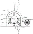
Fig. 32 is a front view of the light irradiation device whose posture is changed so that the processing light is irradiated from an obliquely lower side to an obliquely upper side of the airplane as the object to be processed.
FIG. 33 is a sectional view showing a plurality of second drive systems connecting the light irradiation device shown in FIG. 32 and the first drive system.
Fig. 34 is a sectional view schematically showing the structure of a processing system according to a seventh embodiment.
Fig. 35 shows an example of the terminal effector in fig. 35.
Fig. 36(a) to 36(e) show an example of a terminal effector.
Detailed Description
Hereinafter, embodiments of a machining system, a machining method, a robot system, a connecting device, and a terminal effector device will be described with reference to the drawings. Hereinafter, embodiments of a processing system, a processing method, a robot system, a connecting device, and a terminal effector device will be described with reference to a processing system SYS that processes a coating film SF formed on a surface of an object S to be processed using processing light EL. However, the present invention is not limited to the embodiments described below.
In the following description, positional relationships of various components constituting the machining system SYS are described using an XYZ orthogonal coordinate system defined by X, Y, and Z axes orthogonal to each other. In the following description, for convenience of explanation, the X-axis direction and the Y-axis direction are respectively assumed to be a horizontal direction (i.e., a predetermined direction in a horizontal plane), and the Z-axis direction is assumed to be a vertical direction (i.e., a direction orthogonal to the horizontal plane, and substantially an up-down direction). The rotational directions (in other words, the tilt directions) around the X axis, the Y axis, and the Z axis are referred to as the θ X direction, the θ Y direction, and the θ Z direction, respectively. Here, the Z-axis direction may be a gravitational direction. Further, the XY plane may be set to the horizontal direction.
(1) Processing system SYSa of the first embodiment
First, a machining system SYS according to a first embodiment (hereinafter, the machining system SYS according to the first embodiment is referred to as a "machining system SYSa") will be described.
(1-1) Structure of processing System SYSa
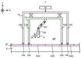
First, the configuration of the machining system SYSa according to the first embodiment will be described with reference to fig. 1. Fig. 1 is a cross-sectional view schematically showing the configuration of a processing system SYSa according to a first embodiment.
As shown in fig. 1, the processing system SYS processes a coating film SF formed (for example, applied) on a surface of an object S. The object S may be a metal, an alloy (e.g., duralumin), a resin (e.g., Carbon Fiber Reinforced Plastic (CFRP)), a glass, or any other material. The coating film SF is a film of paint covering the surface of the object S. Therefore, the coating film SF may also be referred to as a paint layer. The object S serves as a base material for the coating film SF. The thickness of the coating film SF is, for example, several tens of micrometers to several hundreds of micrometers, but may be any other size. The paint constituting the coating film SF may include, for example, a resinous paint or other paint. The resin-made coating material may include at least one of an acrylic coating material (e.g., a coating material containing an acrylic polyol), a polyurethane coating material (e.g., a coating material containing a polyurethane polyol), a polyester coating material (e.g., a coating material containing a polyester polyol), a vinyl coating material, a fluorine coating material (e.g., a coating material containing a fluorine polyol), a silicon coating material, and an epoxy coating material.
Fig. 1 shows an example in which a machining system SYSa (in particular, a machining apparatus 1 described later provided in the machining system SYSa) is disposed on a machining target S having a surface along a horizontal plane (i.e., an XY plane). However, the machining system SYSa is not limited to being disposed on the machining object S having a surface along a horizontal plane. For example, as will be described in detail below with reference to fig. 8 and the like, the machining system SYSa may be disposed on the object S having a surface intersecting a horizontal plane. The machining system SYSa may be disposed so as to be suspended from the object S. In this case, for convenience, the X-axis direction and the Y-axis direction may be defined as a direction along the surface of the object S (typically, a parallel direction), and for convenience, the Z-axis direction may be defined as a direction intersecting the surface of the object S (typically, an orthogonal direction).
The processing system SYSa irradiates the processing light EL to the coating film SF in order to process the coating film SF. The processing light EL may be any light as long as the coating film SF can be processed by being irradiated to the coating film SF. For example, the processing light EL may be laser light. The processing light EL may be any light having any wavelength as long as the coating film SF can be processed by being irradiated to the coating film SF. In the first embodiment, an example in which the processing light EL is invisible light (for example, at least one of infrared light and ultraviolet light) will be described. That is, in the first embodiment, the description will be made using an example in which the processing light EL is at least one of light having a wavelength included in a wavelength range shorter than the wavelength range of visible light and light having a wavelength included in a wavelength range longer than the wavelength range of visible light. However, the processing light EL may be visible light.
Now, the processing of the coating film SF using the processing light EL will be described with reference to fig. 2(a) and 2 (b). Fig. 2(a) and 2(b) are cross-sectional views each schematically showing the processing of the coating film SF formed on the surface of the object S.
As shown in fig. 2(a), the processing system SYSa irradiates the processing light EL to the target irradiation area EA set on the surface of the coating film SF. The target irradiation area EA is an area to which the processing light EL is to be irradiated by the processing system SYSa. As shown in fig. 2(a), when the processing light EL is irradiated to the target irradiation area EA, a part of the coating film SF overlapping the target irradiation area EA (i.e., the coating film located on the-Z side of the target irradiation area EA) is evaporated by the processing light EL. At this time, the coating film SF overlapping the target irradiation region EA does not evaporate entirely in the thickness direction of the coating film SF. That is, in the thickness direction of the coating film SF, a part of the coating film SF overlapping the target irradiation region EA (specifically, a part of the coating film SF relatively close to the target irradiation region EA) evaporates, and the other part of the coating film SF overlapping the target irradiation region EA (specifically, a part of the coating film SF relatively far from the target irradiation region EA) does not evaporate. In other words, the coating film SF is evaporated only to such an extent that the object S is not exposed from the coating film SF. Therefore, the characteristics of the processing light EL can be set to desired characteristics such that only the coating film SF is evaporated to such an extent that the object S is not exposed from the coating film SF. The characteristics of the processing light EL may be set to desired characteristics that do not affect the object S to be processed by irradiation with the processing light EL. The characteristics of the processing light EL can be set to desired characteristics that affect only the coating film SF by irradiation with the processing light EL. The characteristic of the processing light EL may include at least one of a wavelength of the processing light EL, an amount of energy per unit time and/or unit area transmitted from the processing light EL to the surface of the coating film SF, an intensity distribution of the processing light EL on the surface of the coating film SF, an irradiation time of the processing light EL on the surface of the coating film SF, and a size (for example, a dot diameter or an area) of the processing light EL on the surface of the coating film SF.
At this time, the energy (i.e., intensity) of the processing light EL irradiated to the coating film SF is determined so as not to affect the object S by the irradiation of the processing light EL. The energy of the processing light EL is determined so that the processing light EL does not penetrate the coating film SF and reach the object S. In other words, the energy of the processing light EL is defined so as to affect only the coating film SF by irradiation of the processing light EL.
As a result, the coating film SF is removed from the evaporated portion of the coating film SF. On the other hand, the coating film SF remains in the non-evaporated portion of the coating film SF. That is, as shown in fig. 2(b), the coating film SF is partially removed at a portion irradiated with the processing light EL. As a result, as shown in fig. 2(b), the thickness of the coating film SF is reduced in the portion irradiated with the processing light EL compared with the portion not irradiated with the processing light EL. In other words, as shown in fig. 2(b), a relatively thick coating film SF due to the processing light EL not being irradiated and a relatively thin coating film SF due to the processing light EL being irradiated exist on the surface of the object S. That is, the thickness of the coating film SF is adjusted at least partially by irradiation of the processing light EL. By irradiation of the processing light EL, a part of the coating film SF is removed in the thickness direction (Z-axis direction in the example shown in fig. 2 (b)). As a result, a concave portion (in other words, a groove portion) C corresponding to a relatively thin portion of the coating film SF is formed on the surface of the coating film SF. Therefore, the "operation of processing the coating film SF" in the first embodiment includes at least one of an operation of adjusting the thickness of the coating film SF, an operation of removing a part of the coating film SF, and an operation of forming the concave portion C in the coating film SF.
The coating film SF is evaporated by absorbing the processing light EL. That is, the energy of the processing light EL is transmitted to the coating film SF, and the coating film SF is removed by, for example, photochemical decomposition. When the processing light EL is laser light, a phenomenon in which energy of the processing light EL is transmitted to the coating film SF and the coating film SF is removed by photochemical decomposition may be referred to as laser ablation. Therefore, the coating film SF contains a material that can absorb the processing light EL. Specifically, for example, the coating film SF may contain a material whose absorption rate with respect to the processing light EL (for example, in the case where the processing light EL is invisible light, the absorption rate with respect to light in a wavelength range including a wavelength different from that of visible light) is equal to or higher than a predetermined first absorption threshold. Conversely, light in a wavelength range in which the absorptance of the coating film SF is equal to or greater than a predetermined first absorption threshold may be used as the processing light EL.
The material constituting the coating film SF may contain a coloring matter (specifically, for example, at least one of a pigment and a dye). In the case where the coating film SF contains a pigment, the pigment may be a pigment that exhibits a desired color when irradiated with visible light. As a result, the coating film SF including such a pigment will exhibit a desired color. In this case, the coloring matter may have a characteristic such that the coating film SF has a desired color, and the absorption rate of light in a first wavelength range including a wavelength of light in a visible light wavelength range, which is recognized as the desired color by being reflected by the coating film SF, is different from the absorption rate of light in a second wavelength range different from the first wavelength range in the visible light. For example, the dye may have a characteristic that the absorbance of light in the first wavelength range is smaller than the absorbance of light in the second wavelength range. For example, the dye may have a characteristic that the absorptance of light in the first wavelength range is equal to or less than a predetermined second absorption threshold (where the second absorption threshold is smaller than the first absorption threshold), and the absorptance of light in the second wavelength range is equal to or more than a predetermined third absorption threshold (where the third absorption threshold is larger than the second absorption threshold). An example of such a dye that can absorb the processing light EL as invisible light and exhibit a desired color is a near infrared absorbing dye (for example, 4- ((E) -2- { (3E) -2-chloro-3- [2- (2, 6-diphenyl-4H-thiopyran-4-ylidene) ethylene ] cyclohex-1-en-1-yl } vinyl) -2, 6-diphenylthiopyrylium tetrafluoroborate) manufactured by spectral information (Spectrum Info) co. When the coating film SF is transparent, the coating film SF may not contain a coloring matter.
When the coating film SF contains a pigment, the pigment may be transparent to visible light. As a result, the coating film SF containing such a coloring matter becomes a transparent film (so-called clear coat). The term "transparent film" as used herein may also mean a film through which light in at least a part of the visible light wavelength range passes. In this case, the pigment may have a property of absorbing less visible light (i.e., reflecting accordingly) so that the coating film SF becomes transparent. For example, the dye may have a characteristic that the absorbance of visible light is less than a predetermined fourth absorption threshold. An example of such a dye that can absorb the processing light EL as invisible light and is transparent to visible light correspondingly includes, for example, a near-infrared absorbing dye manufactured by spectral information (Spectrum Info) Inc. (for example, 6-chloro-2- [ (E) -2- (3- { (E) -2- [ 6-chloro-1-ethylbenzo [ cd ] indol-2 (1H) -ylidene ] ethylidene } -2-phenyl-1-cyclopenten-1-yl) vinyl ] -1-ethylbenzo [ cd ] indolium tetrafluoroborate).
Referring back to fig. 1 again, the processing system SYSa includes a processing device 1 and a control device 2 in order to process the coating film SF. Further, the processing apparatus 1 includes a light irradiation device 11, a drive system 12, a housing device 13, a support device 14, a drive system 15, an exhaust device 16, a gas supply device 17, and a position measurement device 18.
The light irradiation device 11 can irradiate the processing light EL to the coating film SF under the control of the control device 2. In order to irradiate the processing light EL to the coating film SF, the light irradiation device 11 includes a light source system 111 capable of emitting the processing light EL, and an optical system 112 for guiding the processing light EL emitted from the light source system 111 to the coating film SF, as shown in fig. 3(a), which is a cross-sectional view schematically showing the configuration of the light irradiation device 11.
The light source system 111 emits a plurality of processing lights EL at the same time, for example. However, the light source system 111 may emit a single processing light EL. In this case, the light irradiation device 11 may emit the single processing light EL. In order to emit a plurality of processing lights EL, the light source system 111 includes a plurality of light sources 1111 as shown in fig. 3(b), which is a cross-sectional view schematically showing an example of the configuration of the light source system 111. The plurality of light sources 1111 are arranged in a line at equal intervals. Each light source 1111 emits pulsed light as processing light EL. When the emission time width (hereinafter referred to as "pulse width") of the pulsed light is shortened, the processing accuracy (for example, the accuracy of forming a groove structure described later) is improved. Therefore, each light source 1111 may emit pulsed light having a relatively short pulse width as the processing light EL. For example, each light source 1111 may emit pulsed light having a pulse width of 1000 nanoseconds or less as the processing light EL. For example, each light source 1111 may emit pulsed light with a pulse width of picoseconds or femtosecond as the processing light EL. Alternatively, as shown in fig. 3(c), which is a cross-sectional view schematically showing another example of the configuration of the light source system 111, the light source system 111 may include a single light source 1111 and a splitter 1112 for splitting light from the single light source 1111 into a plurality of processing lights EL. The plurality of emission ports for emitting the plurality of processing light EL branched by the branching unit 1112 are arranged in a line at equal intervals. As an example of the splitter 1112, at least one of a fiber coupler, a waveguide type splitter, a lens array, a diffractive optical element, a spatial light modulator, and the like can be cited.
The optical system 112 includes a focusing lens 1121, a galvanometer mirror 1122, and an f θ lens 1123. The plurality of processing lights EL are irradiated to the coating film SF through the focusing lens 1121, the galvanometer mirror 1122, and the f θ lens 1123.
The focus lens 1121 includes one or more lenses, and is an optical element for adjusting the position along the optical axis direction of at least a part of the lenses to adjust the convergence position BF of the plurality of processing lights EL (in other words, the light converging position or the irradiation position in the optical axis direction, that is, the focal position of the optical system 112). The galvanometer mirror 1122 deflects the plurality of processing lights EL so that the plurality of processing lights EL scan the surface of the coating film SF (that is, the plurality of target irradiation regions EA irradiated with the plurality of processing lights EL, respectively, move on the surface of the coating film SF). That is, the galvanometer mirror 1122 functions as an irradiation position changing device that changes the irradiation position of the plurality of processing lights EL on the coating film SF with respect to the light irradiation device 11. Further, the plurality of processing lights Elk emitted from the optical system 112 can also be swept across the surface of the coating film SF by the galvanometer mirror 1122. The galvanometer mirror 112 includes an X-scan mirror 1122X and a Y-scan mirror 1122Y. The X-scan mirror 1122X reflects the plurality of processing lights EL toward the Y-scan mirror 1122Y. The X-scan mirror 1122X can oscillate or rotate in the oy direction (i.e., a direction of rotation about the Y axis). The plurality of processing lights EL scan the surface of the coating film SF in the X-axis direction by the oscillation or rotation of the X-scan mirror 1122X. By the swinging or rotation of the X-scan mirror 1122X, the plurality of target irradiation areas EA move on the coating film SF along the X-axis direction. The X-scan mirror 1122X changes the relative positional relationship along the X-axis direction between the target irradiation regions EA and the coating film SF. The Y-scan mirror 1122Y reflects the plurality of processing lights EL toward the f θ lens 1123. The Y-scan mirror 1122Y can oscillate or rotate in the ox direction (i.e., the direction of rotation about the X-axis). The plurality of processing lights EL scan the surface of the coating film SF in the Y-axis direction by the oscillation or rotation of the Y-scan mirror 1122Y. The plurality of target irradiation areas EA are moved on the coating film SF along the Y-axis direction by the swing or rotation of the Y-scan mirror 1122Y. The Y-scan mirror 1122Y changes the relative positional relationship along the Y-axis direction between the target irradiation regions EA and the coating film SF. The f θ lens 1123 is an optical element for condensing the plurality of processing lights EL from the galvanometer mirror 1122 on the coating film SF.
The f θ lens 1123 is an end optical element located on the most light-outgoing side of the optical system 112 (in other words, closest to the coating film SF or located at the end of the optical path of the plurality of processing lights EL) among the optical elements included in the optical system 112. However, the optical system 112 may include an optical element (e.g., a cover lens) provided on the light exit side of the f θ lens 1123. The f θ lens 1123 may be detachable from the optical system 112. As a result, after the old f θ lens 1123 is removed from the optical system 112, another f θ lens 1123 is mounted on the optical system 112. However, when the optical system 112 includes an optical element (for example, a protective lens) provided on the light-emitting side of the f θ lens 1123, the optical element may be a terminal optical element, and the optical element may be detachable from the optical system 112.
The traveling directions of the plurality of processing lights EL from the optical system 112 are, for example, parallel to each other. As a result, in the first embodiment, the coating film SF is simultaneously irradiated with the plurality of processing lights EL having the traveling directions parallel to each other. That is, a plurality of target irradiation areas EA are simultaneously set on the coating film SF. Therefore, the productivity (throughput) associated with the processing of the coating film SF is improved as compared with the case where the coating film SF is irradiated with a single processing light EL. Further, the traveling directions of the plurality of processing lights EL from the optical system 112 may not be parallel to each other.
The light irradiation device 11 may not include the light source system 111. In this case, the light irradiation device 11 may irradiate the coating film SF with the plurality of processing lights EL emitted from the light source system 111 disposed outside the light irradiation device 11 using the optical system 112. Specifically, for example, as shown in fig. 4, which is a cross-sectional view schematically showing the configuration of the light irradiation device 11 not including the light source system 111, a plurality of processing lights EL may be made to enter the light irradiation device 11 from the light source system 111 disposed outside the light irradiation device 11 through the light transmission member 113 such as an optical fiber. The light irradiation device 11 may also irradiate the coating film SF with the plurality of processing lights EL incident on the light irradiation device 11 via the conveyance member 113 using the optical system 112. Although fig. 4 shows an example in which the optical system 112 is housed in the housing 114, the optical system 112 may not be housed in the housing 114. That is, the light irradiation device 11 may or may not include the housing 114. Even when the light irradiation device 11 includes the light source system 111, the optical system 112 may be housed in the housing 114, or the optical system 112 may not be housed in the housing 114. The light source system 111 may be housed in the housing 114, or the light source system 111 may not be housed in the housing 111. Here, as the light transmission member 113, a light pipe (light pipe), a relay optical system including one or more lenses or mirrors, or the like may be used.
Referring back to fig. 1 again, the drive system 12 moves the light irradiation device 11 relative to the coating film SF (i.e., relative to the object S having the coating film SF formed on the surface) under the control of the control device 2. That is, the drive system 12 moves the light irradiation device 11 relative to the coating film SF to change the relative positional relationship between the light irradiation device 11 and the coating film SF. When the relative positional relationship between the light irradiation device 11 and the coating film SF is changed, the relative positional relationship between the target irradiation regions EA to which the processing lights EL are irradiated and the coating film SF is also changed. Therefore, the drive system 12 may move the light irradiation device 11 relative to the coating film SF to change the relative positional relationship between the target irradiation regions EA and the coating film SF.
The drive system 12 may also move the light irradiation device 11 along the surface of the coating film SF. In the example shown in fig. 1, the surface of the coating film SF is a plane parallel to at least one of the X axis and the Y axis, and therefore the driving system 12 can also move the light irradiation device 11 along at least one of the X axis and the Y axis. As a result, the target irradiation area EA moves on the coating film SF along at least one of the X axis and the Y axis. That is, the range in which the light irradiation device 11 can irradiate the processing light EL is changed. The drive system 12 may also move the light irradiation device 11 in the thickness direction of the coating film SF (i.e., the direction intersecting the surface of the coating film SF). In the example shown in fig. 1, the thickness direction of the coating film SF is a direction along the Z axis, and therefore the driving system 12 can also move the light irradiation device 11 along the Z axis direction. The driving system 12 may also move the light irradiation device 11 in at least one rotational direction of the ox direction, the oy direction, and the oz direction in addition to the movement in at least one of the X axis, the Y axis, and the Z axis.
The drive system 12 supports the light irradiation device 11 and moves the light irradiation device 11 supported thereby. In this case, the driving system 12 may include, for example, a first support member for supporting the light irradiation device 11, and a first moving mechanism for moving the first support member.
In the first embodiment, the driving system 12 includes a first driving system 121 and a second driving system 122. In the first drive system 121, a second drive system 121 is mounted. The first drive system 121 supports the second drive system 122. The light irradiation device 11 is mounted on the second drive system 122 via the mounting member 19. The second driving system 122 supports the light irradiation device 11 via the mounting member 19. Therefore, the second drive system 122 can substantially function as a connection device for connecting the first drive system 121 and the light irradiation device 11. Further, the second driving system 122 may support the light irradiation device 11 without the mounting member 19. For example, the second driving system 122 may support the light irradiation device 11 by supporting the frame 114 shown in fig. 4.
The first drive system 121 moves the second drive system 122 relative to the coating film SF under the control of the control device 2. That is, the first drive system 121 functions as a moving device that moves the second drive system 122 relative to the coating film SF. Since the light irradiation device 11 is attached to the second drive system 122, it can be said that the first drive system 121 moves the light irradiation device 11 with respect to the coating film SF by moving the second drive system 122. That is, the first drive system 121 moves the light irradiation device 11 together with the second drive system 122. The second drive system 122 moves the second drive system 122 relative to the coating film SF under the control of the control device 2. That is, the second drive system 122 functions as a moving device that moves the light irradiation device 11 relative to the coating film SF.
The specific configurations of the first and second driving systems 121 and 122 will be described in detail later (see fig. 5 and 6), and thus the detailed description thereof is omitted.
The housing device 13 includes a top member 131 and a partition wall member 132. The top member 131 is disposed on the + Z side of the light irradiation device 11. The top member 131 is a plate-like member along the XY plane. The top member 131 supports the drive system 12. Specifically, the first drive system 121 is mounted on the top member 131. That is, the top member 131 supports the first drive system 121. Further, as described above, since the second drive system 122 is mounted on the first drive system 121, the second drive system 122 is mounted on the top member 131 via the first drive system 121. That is, the top member 131 supports the second drive system 122 via the first drive system 121. Further, as described above, since the light irradiation device 11 is mounted on the second drive system 122, the light irradiation device 11 is mounted on the top member 131 via the first drive system 121 and the second drive system 122. The top member 131 supports the light irradiation device 11 via the first driving system 121 and the second driving system 122. A partition wall member 132 is disposed at (or near) the outer edge of the-Z side surface of the top member 131. The partition wall member 132 is a cylindrical (e.g., cylindrical or rectangular cylindrical) member extending from the top member 131 toward the-Z side. The space surrounded by the top member 131 and the partition member 132 becomes a housing space SP for housing the light irradiation device 11 and the drive system 12. Therefore, the driving system 12 moves the light irradiation device 11 in the housing space SP. Further, the housing space SP includes a space between the light irradiation device 11 and the coating film SF (particularly, a space including an optical path of the processing light EL). More specifically, the housing space SP includes a space between the end optical element (for example, the f θ lens 1123) provided in the light irradiation device 11 and the coating film SF (particularly, a space including the optical path of the processing light EL).
The top member 131 and the partition wall member 132 are members capable of shielding the processing light EL. That is, the top member 131 and the partition wall members 132 are opaque to the wavelength of the processing light EL. As a result, the processing light EL propagating through the housing space SP does not leak to the outside of the housing space SP (i.e., the outside of the housing device 13). The top member 131 and the partition wall member 132 may be members that can dim the processing light EL. That is, each of the top member 131 and the partition wall member 132 may be translucent to the wavelength of the processing light EL. Further, each of the top member 131 and the partition wall member 132 is a member that does not transmit (i.e., can shield) unnecessary substances generated by irradiation of the processing light EL. As an example of the unnecessary substance, vapor of the coating film SF can be cited. As a result, the unnecessary material generated in the housing space SP does not leak to the outside of the housing space SP (i.e., the outside of the housing device 13).
An end portion (specifically, an end portion on the coating film SF side, in the example shown in fig. 1, an end portion on the-Z side) 134 of the partition wall member 132 may contact the surface of the coating film SF. When the end 134 contacts the coating film SF, the storage device 13 (i.e., the top member 131 and the partition wall member 132) maintains the sealing of the storage space SP in cooperation with the coating film SF. When the end portion 134 comes into contact with the coating film SF, the shape thereof (in particular, the shape of a contact surface (a surface on the-Z side in the example shown in fig. 1) of the end portion 134 that comes into contact with the coating film SF) can be changed according to the shape of the surface of the coating film SF, and the same applies hereinafter). For example, in the case of the coating film SF in which the contact surface of the end portion 134 is a planar shape, the shape of the end portion 134 becomes a planar shape similarly to the coating film SF. For example, in the case of the coating film SF having a curved contact surface of the end 134, the shape of the end 134 is curved in the same manner as the coating film SF. As a result, the sealing property of the housing space SP is improved compared to the case where the shape of the end 134 cannot be changed in accordance with the shape of the surface of the coating film SF. As an example of the shape-changeable end portion 134, an end portion 134 formed of a member having elasticity (in other words, a soft member) such as rubber is cited. As the shape-changeable end 134, for example, a bellows-shaped end having an elastic structure may be used.
The end 134 may be in contact with the coating film SF and may be attached to the coating film SF. For example, the end portion 134 may also include an adsorption mechanism that can be adsorbed to the coating film SF. When the end 134 adheres to the coating film SF, the sealing property of the housing space SP is further improved as compared with the case where the end 134 does not adhere to the coating film SF. However, the end 134 may not be attachable to the coating film SF. At this time, as long as the end 134 contacts the coating film SF, the sealing property of the housing space SP can be maintained accordingly.
The partition wall member 132 is a member that can be extended and contracted in the Z-axis direction by a drive system (e.g., an actuator), not shown, that operates under the control of the control device 2. For example, the partition wall member 132 may be a bellows-shaped member (so-called bellows). At this time, the partition wall member 132 can be expanded and contracted by the expansion and contraction of the bellows portion. Alternatively, for example, the partition wall member 132 may also include a telescopic tube (telescope pipe) composed of a plurality of hollow cylindrical members having different diameters. At this time, the partition wall member 132 can be expanded and contracted by the relative movement of the plurality of cylindrical members. The state of the partition wall member 132 can be set to at least a first elongated state in which the length in the Z-axis direction is relatively long by the partition wall member 132 extending in the Z-axis direction, and a first contracted state in which the length in the Z-axis direction is relatively short by the partition wall member 132 contracting in the Z-axis direction.
In the case where the partition wall member 132 is in the first elongated state, the end portion 134 is in the first contact state that can contact the coating film SF. On the other hand, in the case where the partition wall member 132 is in the first contracted state, the end portion 134 is in the first non-contact state not contacting the coating film SF. That is, when the partition wall member 132 is in the first contracted state, the end portion 134 is in the first non-contact state away from the coating film SF toward the + Z side. The configuration for switching the state of the end portion 134 between the first contact state and the first non-contact state is not limited to the configuration for expanding and contracting the partition wall member 132. For example, the state of the end portion 134 may be switched between the first contact state and the first non-contact state by configuring the housing device 13 to be movable in the ± Z direction.
The housing means 13 further comprises detection means 135. The detection device 135 detects unnecessary substances (i.e., substances generated by irradiation of the processing light EL) in the housing space SP. As described in detail later, the detection result of the detection device 135 is referred to by the control device 2 when the state of the partition wall member 132 is changed from the first extended state to the first contracted state.
The supporting device 14 supports the accommodating device 13. The housing device 13 supports the driving system 12 and the light irradiation device 11, and therefore the supporting device 14 substantially supports the driving system 12 and the light irradiation device 11 via the housing device 13. In order to support the housing device 13, the supporting device 14 includes a beam member 141 and a plurality of leg members 142. The beam member 141 is disposed on the + Z side of the housing device 13. The beam member 141 is a beam-like member extending along the XY plane. The beam member 141 supports the housing device 13 via the support member 143. A plurality of leg members 142 are disposed on the beam member 141. The foot member 142 is a rod-shaped member extending from the beam member 141 toward the-Z side.
An end portion (specifically, an end portion on the coating film SF side, and an end portion on the-Z side in the example shown in fig. 1) 144 of the foot member 142 may contact the surface of the coating film SF. As a result, the supporting device 14 is supported by the coating film SF (i.e., the object S). That is, the support device 14 supports the housing device 13 in a state where the end portion 144 contacts the coating film SF (in other words, a state where the support device 14 is supported by the coating film S). Similarly to the end 134 of the housing device 13, the shape of the end 144 may be changed depending on the shape of the surface of the coating film SF when the end is in contact with the coating film SF (in particular, the shape of the contact surface (the surface on the-Z side in the example shown in fig. 1) of the end 144 that contacts the coating film SF, which will be the same hereinafter). The end portion 144 may be in contact with the coating film SF and may be attached to the coating film SF. For example, the end portion 144 may also include an adsorption mechanism that can adsorb to the coating film SF. If the end portion 144 is attached to the coating film SF, the stability of the supporting device 14 is improved as compared with the case where the end portion 144 is not attached to the coating film SF. However, the end portion 144 may not be attachable to the coating film SF.
The beam member 141 is a member that is extendable and retractable along at least one of the X axis and the Y axis (or in any direction along the XY plane) by the drive system 15 operating under the control of the control device 2. For example, the beam member 141 may also include a sleeve bellows combined from a plurality of barrel members having different diameters. At this time, the beam member 141 can be extended and contracted by the relative movement of the plurality of tube members.
The foot member 142 is a member that is extendable and retractable in the Z-axis direction by the drive system 15 operating under the control of the control device 2. For example, foot member 142 may also comprise a sleeve extension tube made up of a plurality of barrel members having different diameters. At this time, the foot member 142 can be extended and contracted by the relative movement of the plurality of tube members. The state of the foot member 142 can be set to at least a second extended state in which the length in the Z-axis direction is relatively long by the foot member 142 extending in the Z-axis direction, and a second contracted state in which the length in the Z-axis direction is relatively short by the foot member 142 contracting in the Z-axis direction. In the case where the foot member 142 is in the second elongated state, the end portion 144 is in a second contact state that can contact the coating film SF. On the other hand, when the leg member 142 is in the second contracted state, the end portion 144 is in a second non-contact state where it does not contact the coating film SF. That is, when the leg member 142 is in the second contracted state, the end portion 144 is in the second non-contact state separated from the coating film SF toward the + Z side.
The drive system 15 moves the support device 14 relative to the coating film SF (i.e., relative to the object S having the coating film SF formed on the surface) under the control of the control device 2. That is, the drive system 15 moves the support device 14 relative to the coating film SF to change the relative positional relationship between the support device 14 and the coating film SF. The supporting device 14 supports the housing device 13, and therefore the driving system 15 substantially moves the housing device 13 relative to the coating film SF by moving the supporting device 14. That is, the drive system 15 substantially moves the support device 14 relative to the coating film SF to change the relative positional relationship between the housing device 13 and the coating film SF. Further, the housing device 13 supports the light irradiation device 11 via the drive system 12. Therefore, the drive system 15 can substantially move the light irradiation device 11 relative to the coating film SF by moving the support device 14. That is, the drive system 15 can substantially move the support device 14 relative to the coating film SF to change the relative positional relationship between the light irradiation device 11 and the coating film SF. In other words, the driving system 15 can substantially move the supporting device 14 relative to the coating film SF to change the relative positional relationship between the target irradiation areas EA and the coating film SF.
The driving system 15 extends and contracts the beam member 141 under the control of the control device 2 in order to move the supporting device 14. Further, the drive system 15 extends and contracts the plurality of leg members 142 under the control of the control device 2 in order to move the support device 14. The movement of the support device 14 by the drive system 15 will be described in detail below with reference to fig. 9 to 20.
The exhaust device 16 is connected to the housing space SP via an exhaust pipe 161. The exhaust device 16 can exhaust the gas in the housing space SP. In particular, the exhaust device 16 can exhaust the gas in the housing space SP, thereby sucking the unnecessary material generated by the irradiation of the processing light EL from the housing space SP to the outside of the housing space SP. In particular, when the unnecessary substance exists on the optical path of the processing light EL, the irradiation of the processing light EL to the coating film SF may be affected. Therefore, the exhaust device 16 sucks the unnecessary substances together with the gas in the space, particularly from the space including the optical path of the processing light EL between the end optical element of the optical system 112 and the coating film SF. The unnecessary material sucked from the housing space SP by the exhaust device 16 is discharged to the outside of the processing apparatus 1 through the filter 162. The filter 162 adsorbs unnecessary substances. Again, the filter 162 may be removable or replaceable.
The gas supply device 17 is connected to the housing space SP via a gas suction pipe 171. The gas supply device 17 can supply gas to the housing space SP. The gas supplied to the housing space SP may be at least one of Air, Clean Dry Air (CDA), and inert gas. As an example of the inert gas, nitrogen gas can be cited. In the first embodiment, the gas supply device 17 is configured to supply CDA. Therefore, the housing space SP is a space flushed by the CDA. At least a part of the CDA supplied to the housing space SP is sucked by the exhaust device 16. The exhaust device 16 exhausts the CDA sucked from the housing space SP to the outside of the processing system SYSa through the filter 162.
The gas supply device 17 supplies a gas such as CDA to an optical surface 1124 on the housing space SP side of the f θ lens 1123 (i.e., an optical surface on the housing space SP side of the end optical element of the optical system 112) shown in fig. 3. Since the optical surface 1124 faces the housing space SP, it may be exposed to unnecessary substances generated by irradiation of the processing light EL. As a result, an unnecessary substance may be attached to the optical surface 1124. Further, since the processing light EL passes through the optical surface 1124, there is a possibility that the unnecessary substance attached to the optical surface 1124 is sintered (i.e., fixed) by the processing light EL passing through the optical surface 1124. The unnecessary substance attached (and further fixed) to the optical surface 1124 is likely to become a stain on the optical surface 1124, which affects the characteristics of the processing light EL. Further, when a gas such as CDA is supplied to the optical surface 1124, the optical surface 1124 can be prevented from coming into contact with an unnecessary substance. Therefore, the adhesion of stains to the optical surface 1124 is prevented. Therefore, the gas supply device 17 also functions as an adhesion prevention device for preventing adhesion of dirt to the optical surface 1124. Further, even when the optical surface 1124 has stains attached (and further fixed), the stains may be removed (for example, blown off) by CDA supplied to the optical surface 1124. Therefore, the gas supply device 17 also functions as an adhesion prevention device for removing dirt adhering to the optical surface 1124.
The position measuring device 18 measures the relative positional relationship between the coating film SF and the light irradiation device 11. That is, the position measuring device 18 measures the relative positional relationship between the object S and the light irradiation device 11. In the first embodiment, the position measuring device 18 measures the position of the coating film SF with respect to the light irradiation device 11. That is, the position measuring device 18 measures the position of the object S with respect to the light irradiation device 11.
The position measuring device 18 may measure the coating film SF in order to measure the position of the coating film SF with respect to the light irradiation device 11 (i.e., the position of the object S, which will be the same hereinafter). That is, the position measuring device 18 may measure the object S. At this time, the position measuring device 18 is also referred to as an object measuring device since it measures an object including at least one of the coating film SF and the object S.
The position measurement device 18 may also be arranged at a fixed position with respect to the light irradiation device 11 (in particular, the optical system 112). The position measuring device 18 may be disposed at a position where the relative position with respect to the light irradiation device 11 is fixed. The position measuring device 18 may also be configured to be a position in which the relative positions of the light irradiating device 11 and the position measuring device 18 are unchanged even if the driving system 12 moves the light irradiating device 11. For example, fig. 1 shows an example in which the position measurement device 18 is mounted to a mounting member 19 on which the light irradiation device 11 is mounted. However, the position measuring device 18 may be mounted to a member different from the mounting member 19. For example, the position measuring device 18 may be attached to the light irradiation device 11. For example, the position measuring device 18 may be attached to the housing 114 (see fig. 4).
In the case where the position measuring device 18 is disposed at a fixed position with respect to the light irradiation device 11, the output from the position measuring device 18 (i.e., the measurement result of the position measuring device 18) will include information about the position of the coating film SF with respect to the light irradiation device 11. Specifically, the measurement result of the position measurement device 18 includes information relating to the position of the coating film SF with respect to the position measurement device 18. That is, the measurement result of the position measurement device 18 contains information on the position of the coating film SF on the measurement coordinate system of the position measurement device 18. Here, when the position measurement device 18 is disposed at a position fixed to the light irradiation device 11, the information on the position of the coating film SF with respect to the position measurement device 18 substantially includes information on the position of the coating film SF with respect to the light irradiation device 11 disposed at the position fixed to the position measurement device 18. Therefore, the control device 2 can appropriately determine the position of the coating film SF with respect to the light irradiation device 11.
The position measuring device 18 may be any type of measuring device as long as it can measure the coating film SF. For example, the position measuring device 18 may include an imaging device (i.e., a camera) that can image an object such as the coating film SF. The position measurement device 18 may also include: an irradiation device that irradiates the coating film SF with measurement light in which a predetermined pattern is drawn on the coating film SF; and an imaging device that images a pattern drawn on the coating film SF by the measurement light. In this manner, the position measuring device 18 may be a measuring device that measures the coating film SF in a non-contact manner (for example, at least one of a light detection manner, a sound wave detection manner, and a radio wave detection manner). Furthermore, a plurality of position measuring devices 18 may also be provided. In this case, the measurement axes (typically, optical axes in an optical measurement system such as an imaging system) of the respective position measurement devices 18 may be in a relationship of intersecting with each other (or twisted), or may be parallel to each other (or coaxial).
The control device 2 controls the overall operation of the machining system SYSa. In particular, the control device 2 controls the light irradiation device 11, the drive system 12, the housing device 13, and the drive system 15 so as to form the recess C of a desired shape at a desired position, as described in detail later.
The control device 2 may include a Central Processing Unit (CPU) (or a Graphics Processing Unit (GPU) in addition to or instead of the CPU), and a memory, for example. The control device 2 functions as a device for controlling the operation of the machining system SYSa by executing a computer program by a CPU. The computer program is a computer program for causing the control device 2 (e.g., CPU) to perform (i.e., execute) an operation to be described later to be performed by the control device 2. That is, the computer program is a computer program for causing the control device 2 to function so as to cause the machining system SYSa to perform an operation described below. The computer program executed by the CPU may be recorded in a memory (i.e., a recording medium) provided in the control device 2, or may be recorded in any storage medium (e.g., a hard disk or a semiconductor memory) that can be incorporated in the control device 2 or can be externally provided to the control device 2. Alternatively, the CPU may download (download) a computer program to be executed from an external device of the control device 2 via a network interface.
The control device 2 may not be provided inside the processing system SYSa, and may be provided outside the processing system SYSa as a server (server), for example. In this case, the control device 2 and the processing system SYSa may be connected by a wired and/or wireless network (or a data bus and/or a communication line). For example, a network using a Serial Bus (Serial Bus) interface represented by at least one of Institute of Electrical and Electronic Engineers (IEEE) 1394, RS-232x, RS-422, RS-423, RS-485, and Universal Serial Bus (USB) may be used as the wired network. As the wired network, a network using a parallel bus (parallel bus) interface may be used. As the wired network, a network using an interface conforming to Ethernet (registered trademark) typified by at least one of 10BASE-T, 100BASE-TX, and 1000BASE-T may be used. As the wireless network, a network using radio waves may be used. An example of a Network using radio waves is a Network conforming to ieee802.1x (for example, at least one of a Local Area Network (LAN) and Bluetooth (registered trademark)). As the wireless network, a network using infrared rays may be used. As the wireless network, a network using optical communication may be used. In this case, the control device 2 and the machining system SYSa may be configured to transmit and receive various information via a network. Further, the control device 2 may transmit information such as a command and a control parameter to the machining system SYSa via a network. The processing system SYSa may include a receiving device that receives information such as commands and control parameters from the control device 2 via the network. Alternatively, a first control device that performs a part of the processes to be performed by the control device 2 may be provided inside the processing system SYSa, while a second control device that performs another part of the processes to be performed by the control device 2 may be provided outside the processing system SYSa.
Further, as a recording medium for recording a computer program executed by the CPU, a Compact Disc Read-Only Memory (CD-ROM), a Compact Disc-Recordable (CD-R), a Compact Disc-rewritable (CD-RW) or a floppy Disc (flexible Disc), a magneto-Optical Disc (MO), a Digital Versatile Disc Read-Only Memory (DVD-ROM), a Digital Versatile Disc Random Access Memory (DVD-RAM), a Digital Versatile Disc Recordable (DVD-R), a DVD + R, a rewritable (DVD-RW), a Blu-ray Disc (RW), or the like may be used, Magnetic media such as magnetic tape, semiconductor memory such as optical disk and USB memory, and any other media capable of storing programs. The recording medium may include a machine that can record a computer program (for example, a general-purpose machine or a dedicated machine that is installed with a computer program in a state that the computer program can be executed in at least one form of software (software) or firmware (firmware)). Further, each process or function included in the computer program may be realized by a logic processing block implemented in the control device 2 by the control device 2 (i.e., a computer) executing the computer program, may be realized by hardware (hardware) such as a predetermined Gate Array (FPGA) or an Application Specific Integrated Circuit (ASIC) provided in the control device 2, or may be realized by a form in which the logic processing block is mixed with a local hardware module that realizes a part of the hardware.
(1-2) Structure of drive System 12
Next, the structure of the drive system 12 will be explained. As described above, the driving system 12 includes the first driving system 121 and the second driving system 122, and therefore the structure of the first driving system 121 and the structure of the second driving system 122 are described in sequence below.
(1-2-1) Structure of drive System 121
First, the configuration of the first drive system 121 will be described with reference to fig. 5. Fig. 5 is a sectional view showing the structure of the first drive system 121.
As shown in fig. 5, the first drive system 121 includes a base 1211 and an arm drive system 1212.
The base 1211 is attached to the top member 131 of the storage device 13. An arm drive system 1212 is attached to the base 1211. Base 1211 supports an arm drive system 1211. Base 1211 is used as a base member for supporting arm drive system 1211.
The arm drive system 1212 includes a plurality of arm members 12121. The plurality of arm members 12121 are connected to each other via at least one joint member 12122 so as to be freely swingable. Thus, the arm drive system 1212 is a robot having a so-called vertical articulated structure. Arm drive system 1212 may also include a single joint (i.e., a drive shaft defined by joint member 12122). Alternatively, the arm drive system 1212 may also include multiple joints. Fig. 5 shows an example where the arm drive system 1212 includes three joints. The two arm members 12121 coupled via the joints are swung by the actuators 12123 corresponding to the joints. Fig. 5 shows an example where the arm drive system 1212 includes three actuators 12123 corresponding to three joints. As a result, at least one arm member 12121 moves. Therefore, at least one arm member 12121 is movable relative to the coating film SF. That is, the at least one arm member 12121 is movable to change the relative positional relationship of the at least one arm member 12121 to the coating film SF.
The second drive system 122 is mounted on the arm drive system 1212. Specifically, the second drive system 122 is attached to one arm member 12121 of the plurality of arm members 12121 that is located farthest from the base 1211. Hereinafter, for convenience of explanation, one arm member 12121 to which the second drive system 122 is attached will be referred to as a front end arm member 12124. The second drive system 122 may be directly attached to the front end arm member 12124, or may be indirectly attached to the front end arm member 12124 via another member (e.g., an attachment member 1213 described below with reference to fig. 30 in a sixth embodiment).
When the front end arm member 12124 is moved by the actuator 12123, the second drive system 122 mounted to the front end arm member 12124 also moves. Thus, the arm drive system 1212 (i.e., the first drive system 121) may move the second drive system 122. Specifically, the arm drive system 1212 may move the second drive system 122 relative to the coating film SF. The arm driving system 1212 may move the second driving system 122 to change the relative positional relationship between the second driving system 122 and the coating film SF. When the second driving system 122 moves, the light irradiation device 11 attached to the second driving system 122 also moves. Accordingly, the arm driving system 1212 (i.e., the first driving system 121) may move the light irradiation device 11.
The control device 2 may also control the arm drive system 1212 based on the measurement result of the position measurement device 18. Specifically, the control device 2 may acquire information on the relative positional relationship between the coating film SF and the light irradiation device 11 based on the measurement result of the position measurement device 18, and control the arm drive system 1212 based on the information on the relative positional relationship between the coating film SF and the light irradiation device 11. Further, in the case where the position measurement device 18 includes a camera, the control device 2 may also control the arm drive system 1212 using visual servos (visual servos) based on the measurement results of the position measurement device 18 (i.e., images captured by the camera). Furthermore, visual servoing may also be referred to as vision servoing (vision servo). Also, the light irradiation device 11 may also include an acceleration sensor as a motion measurement sensor for measuring the vibration thereof. At this time, the control device 2 may also control the arm drive system 1212 based on the measurement result of the acceleration sensor.
For example, the control device 2 may control the arm drive system 1212 so that the light irradiation device 11 moves relative to the coating film SF. That is, the control device 2 may control the arm drive system 1212 to change the relative position of the light irradiation device 11 and the coating film SF. At this time, the control device 2 may control the arm drive system 1212 to align the coating film SF with the light irradiation device 11. The control device 2 may control the arm drive system 1212 to align the coating film SF with the target irradiation region EA irradiated with the processing light EL from the light irradiation device 11. For example, the control device 2 may control the arm drive system 1212 to set the target irradiation area EA (i.e., the processing light EL to be irradiated) at a desired position on the coating film SF. The control device 2 may also control the arm drive system 1212 to move the target irradiation area EA on the desired path on the coating film SF. The control device 2 may control the arm driving system 1212 by using an output from an encoder provided at a joint portion of the arm driving system 1212, and detect an angle between the plurality of arm members 12121.
The "relative position between the light irradiation device 11 and the coating film SF" in the first embodiment refers to a relative position between the light irradiation device 11 and the coating film SF in at least one of the X-axis direction, the Y-axis direction, the Z-axis direction, the rotation around the X-axis (i.e., the rotation direction corresponding to the θ X direction), the rotation around the Y-axis (i.e., the rotation direction corresponding to the θ Y direction), and the rotation around the Z-axis (i.e., the rotation direction corresponding to the θ Z direction). That is, the "relative position between the light irradiation device 11 and the coating film SF" in the first embodiment may also include the relative posture between the light irradiation device 11 and the coating film SF.
When the relative position between the light irradiation device 11 and the coating film SF is changed, the relative position between the target irradiation region EA and the coating film SF is changed, and therefore, in addition to or instead of measuring the relative positional relationship between the light irradiation device 11 and the coating film SF, the position measurement device 18 may measure the relative positional relationship between the coating film SF and the irradiation position of the processing light EL (for example, the irradiation position of the processing light EL on the coating film SF). For example, the position measuring device 18 may measure the irradiation position of the processing light EL with respect to the coating film SF at least a part of the period during which the light irradiation device 11 irradiates the coating film SF with the processing light EL. For example, the position measuring device 18 may measure the irradiation position of the processing light EL on the coating film SF (that is, the position to which the processing light EL is actually irradiated, for example, the position of the portion processed by the processing light EL) after the light irradiation device 11 irradiates the coating film SF with the processing light EL. For example, the position measuring device 18 may measure the irradiation position of the processing light EL on the sensitive member (that is, the position of the portion of the sensitive member whose characteristic changes due to the irradiation of the processing light EL) after the irradiation of the processing light EL on the sensitive member (specifically, a member whose characteristic changes due to the irradiation of the processing light EL, for example, the sensitive member PE described in the third embodiment) formed on the coating film SF by the light irradiation device 11. At this time, the control device 2 may control the arm drive system 1212 so as to perform the alignment of the coating film SF with the light irradiation device 11 (i.e., the alignment of the coating film SF with the target irradiation area EA) based on the measurement result of the position measurement device 18. Further, the position measuring device 18 may measure the irradiation position of the processing light EL itself. At this time, the position measuring device 18 may also measure light of the wavelength of the processing light EL.
The first drive system 121 is not limited to the articulated robot, and may have any configuration as long as the second drive system 122 can be moved relative to the coating film SF. For example, the first drive system 121 is an orthogonal multi-axis moving body in which a plurality of linear guides (linear guides) are combined. For example, the present invention may be applied to a perpendicular two-axis moving body in which a first linear guide is provided along a first direction within a predetermined plane, and a second linear guide is provided in a moving body (first moving block) of the first linear guide along a second direction intersecting (typically perpendicular to) the first direction. At this time, the second drive system is mounted to the moving body (second moving block) of the second linear guide. Further, a third linear guide may be provided on the moving body (second moving block) of the second linear guide of the orthogonal two-axis moving body along a third direction intersecting the predetermined plane. In such an orthogonal triaxial moving body, the second drive system 122 may be mounted to a moving body (third moving block) of a third linear guide.
(1-2-2) Structure of the second drive System 122
Next, the configuration of the second drive system 122 will be described with reference to fig. 6. Fig. 6 is a sectional view showing the structure of the second drive system 122.
As shown in fig. 6, the second drive system 122 includes a support member 1221, a support member 1222, an air spring (air spring)1223, a damper (damper) member 1224, and a drive member 1225.
The support member 1221 is mounted to the first drive system 121. Specifically, the support member 1221 is mounted to the front end arm member 12124 of the first drive system 121. The support member 1221 is fixed to the front end arm member 12124 such that the mounted surface 1221a of the support member 1221 and the mounting surface 12124a formed by the foremost end of the front end arm member 12124 are in contact with each other. Here, the mounting surface 12124a may be a portion that moves relative to the coating film SF as an object. The support member 1222 is attached to the light irradiation device 11 via the attachment member 19. The support member 1222 is fixed to the mounting member 19 so that the mounted surface 1222a of the support member 1222 and the first mounting surface 19a of the mounting member 19 contact each other. The light irradiation device 11 is fixed to the mounting member 19 so that the second mounting surface 19b of the mounting member 19 and the mounted surface 11a formed on a part of the outer surface of the light irradiation device 11 contact each other.
The support member 1221 and the support member 1222 are coupled (in other words, coupled or connected) via an air spring 1223, a damper member 1224, and a drive member 1225. Specifically, an air spring 1223, a damper member 1224, and a driving member 1225 are arranged between a second surface (a surface on the-Z side in the example shown in fig. 6) of the support member 1221 opposite to the first surface (a surface on the + Z side in the example shown in fig. 6) on which the first drive system 121 is mounted and a fourth surface (a surface on the + Z side in the example shown in fig. 6) of the support member 1222 opposite to a third surface (a surface on the-Z side in the example shown in fig. 6) on which the mounting member 19 is mounted, so as to couple the support member 1221 and the support member 1222. That is, the air spring 1223, the damper member 1224, and the driving member 1225 are attached to the support member 1221 and the support member 1222, respectively, to couple the support member 1221 and the support member 1222. Since the first driving system 121 is mounted on the support member 1221 and the light irradiation device 11 is mounted on the support member 1222, it can be said that the air spring 1223, the damper member 1224, and the driving member 1225 are substantially mounted on the support member 1221 and the support member 1222, respectively, so as to couple the first driving system 121 and the light irradiation device 11.
The air spring 1223 applies an elastic force due to a pressure of gas (air, for example) to at least one of the support member 1221 and the support member 1222 under the control of the control device 2. The air spring 1223 applies an elastic force due to the gas pressure to at least one of the first drive system 121 and the light irradiation device 11 via at least one of the support member 1221 and the support member 1222 under the control of the control device 2. In particular, the air spring 1223 may apply an elastic force due to the gas pressure to at least one of the support member 1221 and the support member 1222 along the arrangement direction of the support member 1221 and the support member 1222 (the Z-axis direction and the gravity direction in the example shown in fig. 6). That is, the air spring 1223 may apply an elastic force due to the gas pressure to at least one of the first drive system 121 and the light irradiation device 11 via at least one of the support member 1221 and the support member 1222 along the arrangement direction (the Z-axis direction and the gravity direction in the example shown in fig. 6) of the first drive system 121 (particularly, the front end arm member 12124) and the light irradiation device 11. Further, air spring 1223 may also be referred to as a resilient member.
In order to apply elastic force due to the gas pressure, the air spring 1223 is supplied with gas from a gas supply device 12261 via a pipe 12262 and a valve 12263. The control device 2 controls at least one of the gas supply device 12261 and the valve 12263 based on the measurement result of the pressure gauge 1226 that measures the pressure of the body in the air spring 1223. Further, the gas supply device 12261, the pipe 12262, and the valve 12263 may be omitted. At this time, the air spring 1223 may apply an elastic force due to the internal air pressure to at least one of the support member 1221 and the support member 1222 regardless of the control of the controller 2.
The air spring 1223 may support the weight of the support member 1222 by an elastic force under the control of the control device 2. Specifically, the air spring 1223 may support the weight of the support member 1222 by an elastic force along the arrangement direction of the support member 1221 and the support member 1222. Since the light irradiation device 11 is attached to the support member 1222, the air spring 1223 can support the weight of the light irradiation device 11 attached to the support member 1222 by an elastic force. Specifically, the air spring 1223 may support the weight of the light irradiation device 11 by the elastic force along the direction in which the first drive system 121 (particularly, the front end arm member 12124) and the light irradiation device 11 are aligned. In this case, the air spring 1223 may also function as a self-weight eliminator (cancel) for eliminating the self-weight of the light irradiation device 11. The air spring 1223 may support the weight of the support member 1222 by an elastic force regardless of the control device 2.
The air spring 1223 may reduce the vibration transmitted between the first drive system 121 and the light irradiation device 11 via the second drive system 122 by an elastic force under the control of the control device 2. That is, the air spring 1223 may damp vibration transmitted between the first drive system 121 and the light irradiation device 11 via the second drive system 122 by an elastic force. Specifically, the air spring 1223 may also reduce (attenuate) the vibration from the first drive system 121 toward (i.e., transmitted to) the light irradiation device 11 via the second drive system 122 by the elastic force. That is, the air spring 1223 may also reduce (damp) the vibration from the portion of the first drive system 121 to which the second drive system 122 is attached (i.e., the front end arm portion 12124) toward the portion of the light irradiation device 11 to which the second drive system 122 is attached, using the elastic force. At this time, the control device 2 may control at least one of the gas supply device 12261 and the valve 12263 based on the measurement result of the pressure gauge 1226 so as to reduce (i.e., attenuate) the vibration transmitted between the first drive system 121 and the light irradiation device 11 via the second drive system 122. Further, air spring 1223 (or second drive system 122 including air spring 1223) may also be referred to as a vibration reduction device or a vibration attenuation device. The air spring 1223 may reduce the vibration transmitted between the first drive system 121 and the light irradiation device 11 via the second drive system 122 by an elastic force, regardless of the control device 2.
Reducing the vibration from the first driving system 121 toward the light irradiation device 11 may also include: the amount of vibration of the light irradiation device 11 is reduced (i.e., the amplitude of vibration) as compared to the amount of vibration (i.e., the amplitude of vibration) of the first drive system 121. Reducing the vibration from the first driving system 121 toward the light irradiation device 11 may also include: the amount of vibration of the portion of the light irradiation device 11 where the second drive system 122 is mounted is reduced compared to the amount of vibration of the portion of the first drive system 121 where the second drive system 122 is mounted (i.e., the leading arm portion 12124). Reducing the vibration from the first driving system 121 toward the light irradiation device 11 may also include: the amount of vibration of the support member 1222 mounting the light irradiation device 11 is reduced compared to the amount of vibration of the support member 1221 mounting the first driving system 121. When the air spring 1223 does not reduce the vibration from the first drive system 121 toward the light irradiation device 11, the vibration amount of the first drive system 121 is substantially the same as the vibration amount of the light irradiation device 11. That is, the amount of vibration of the support member 1121 is substantially the same as the amount of vibration of the support member 1122. Therefore, reducing the vibration from the first driving system 121 toward the light irradiation device 11 may also include: the amount of vibration of the light irradiation device 11 is reduced compared to a case where the vibration from the first drive system 121 toward the light irradiation device 11 is not reduced. Reducing the vibration from the first driving system 121 toward the light irradiation device 11 may also include: the amount of vibration of the support member 1122 is reduced as compared to the case where the vibration from the first drive system 121 toward the light irradiation device 11 is not reduced. Further, the vibration amount referred to herein may also refer to a vibration amount with respect to some object. For example, the vibration amount of the first driving system 121, the vibration amount of the light irradiation device 11, the vibration amount of the support member 1221, and the vibration amount of the support member 1222 may also refer to the vibration amount of the first driving system 121 with respect to the coating film SF (or the object SF, the same applies hereinafter), the vibration amount of the light irradiation device 11 with respect to the coating film SF, the vibration amount of the support member 1221 with respect to the coating film SF, and the vibration amount of the support member 1222 with respect to the coating film SF, respectively.
The damper member 1224 applies an elastic force due to a factor different from the air pressure to at least one of the support member 1221 and the support member 1222. The damper member 1224 applies an elastic force due to a factor different from the air pressure to at least one of the first drive system 121 and the light irradiation device 11 via at least one of the support member 1221 and the support member 1222. In particular, the damper member 1224 may apply an elastic force to at least one of the support member 1221 and the support member 1222 along the direction in which the support member 1221 and the support member 1222 are arranged (the Z-axis direction and the gravity direction in the example shown in fig. 6). That is, the damper member 1224 may apply an elastic force to at least one of the first drive system 121 and the light irradiation device 11 via at least one of the support member 1221 and the support member 1222 along the direction in which the first drive system 121 (particularly the distal end arm member 12124) and the light irradiation device 11 are arranged (the Z-axis direction and the gravity direction in the example shown in fig. 6). Further, the damper member 1224 may also be referred to as a resilient member.
The damper member 1224 may be any member as long as it can impart an elastic force. For example, the damper member 1224 may also include a compression spring coil. For example, the damper member 1224 can also comprise a leaf spring.
The damper member 1224 may also utilize a spring force to support the weight of the support member 1222. Specifically, the damper member 1224 may also support the weight of the support member 1222 by using an elastic force along the arrangement direction of the support member 1221 and the support member 1222. Since the light irradiation device 11 is attached to the support member 1222, the damper member 1224 may support the weight of the light irradiation device 11 attached to the support member 1222 by an elastic force. Specifically, the damper member 1224 may support the weight of the light irradiation device 11 along the direction in which the first drive system 121 (particularly, the front end arm member 12124) and the light irradiation device 11 are aligned by the elastic force. In this case, the damper member 1224 can also function as a weight eliminator for eliminating the weight of the light irradiation device 11.
The damper member 1224 may also reduce vibration transmitted between the first driving system 121 and the light irradiation device 11 via the second driving system 122 by using elastic force. That is, the damper member 1224 may damp vibration transmitted between the first drive system 121 and the light irradiation device 11 via the second drive system 122 by an elastic force. Specifically, the damper member 1224 may also reduce (damp) the vibration from the first drive system 121 toward (i.e., transmitted to) the light irradiation device 11 via the second drive system 122 by using the elastic force. Accordingly, the damper member 1224 (or the second drive system 122 including the damper member 1224) may also be referred to as a vibration reducing device or a vibration attenuating device.
The driving member 1225 may generate a driving force under the control of the control device 2. The driving member 1225 may impart the generated driving force to at least one of the support member 1221 and the support member 1222. The driving member 1225 may impart the generated driving force to at least one of the first driving system 121 and the light irradiation device 11 via at least one of the support member 1221 and the support member 1222. The driving member 1225 may have any structure as long as it can generate a driving force. For example, the driving member 1225 may also have a structure that can electrically generate a driving force. For example, the driving member 1225 may also have a structure that can magnetically generate a driving force. As an example, fig. 6 shows an example in which the driving member 1225 is a Voice Coil Motor (VCM) capable of electrically generating a driving force. Further, the voice coil motor is one of linear motors, but the driving member 1225 may be a linear motor different from the voice coil motor. The driving member 1225 may be one that generates a driving force along a linear axis.
Further, the driving member 1225 may have a structure in which a member of the driving member 1225 attached to the supporting member 1221 is not in physical contact with a member of the driving member 1225 attached to the supporting member 1222. For example, in the case where the driving member 1225 is a voice coil motor, a member (e.g., a member including any one of a coil and a magnetic pole) of the driving member 1225 that is attached to the supporting member 1221 is not in physical contact with a member (e.g., a member including the other of a coil and a magnetic pole) of the driving member 1225 that is attached to the supporting member 1222.
The driving member 1225 may move at least one of the support member 1221 and the support member 1222 by a driving force under the control of the control device 2. The driving member 1225 may move at least one of the first driving system 121 and the light irradiation device 11 by moving at least one of the support member 1221 and the support member 1222 by a driving force under the control of the control device 2. At this time, the driving member 1225 may change the relative position of the first driving system 121 and the light irradiation device 11 by moving at least one of the first driving system 121 and the light irradiation device 11 by the driving force. In the first embodiment, the "relative position between the first drive system 121 and the light irradiation device 11" refers to the relative position between the first drive system 121 and the light irradiation device 11 in at least one of the X-axis direction, the Y-axis direction, the Z-axis direction, the rotation around the X-axis, the rotation around the Y-axis, and the rotation around the Z-axis. That is, the "relative position between the first drive system 121 and the light irradiation device 11" in the first embodiment may also include the relative posture between the first drive system 121 and the light irradiation device 11. At this time, it can be said that the second drive system 122 including the drive means 1225 couples the first drive system 121 and the light irradiation device 11 so that the relative positions of the first drive system 121 and the light irradiation device 11 can be changed. That is, it can be said that the air spring 1223 and the damper member 1224 (and the driving member 1225) are coupled to the first driving system 121 and the light irradiation device 11 so that the relative positions of the first driving system 121 and the light irradiation device 11 can be changed by the driving member 1225. The driving member 1225 may also be referred to as a position changing device.
The driving means 1225 may change the relative position of the first driving system 121 and the light irradiation device 11 based on the measurement result of the position measurement device 1227 included in the second driving system 122 under the control of the control device 2. The position measuring device 1226 measures the relative position of the first drive system 121 and the light irradiation device 11. For example, the position measuring device 1226 may be an encoder including a detecting portion 12261 attached to the support member 1221 and a scale portion 12262 attached to the support member 1222. The measurement result of the position measurement device 1226 contains information relating to the relative positions of the support member 1221 and the support member 1222. Since the first driving system 121 is mounted on the support member 1221 and the light irradiation device 11 is mounted on the support member 1222, the information on the relative positions of the support member 1221 and the support member 1222 includes information on the relative positions of the first driving system 121 and the light irradiation device 11. Thus, the control device 2 can appropriately determine the relative position of the first drive system 121 and the light irradiation device 11. As a result, the control device 2 can appropriately change the relative position of the first drive system 121 and the light irradiation device 11 based on the measurement result of the position measurement device 1227.
The driving means 1225 may move the light irradiation device 11 with respect to the coating film SF by changing the relative position between the first driving system 121 and the light irradiation device 11 (typically, moving the light irradiation device 11 with respect to the first driving system 121) under the control of the control device 2. The driving means 1225 may also move the light irradiation device 11 to change the relative positional relationship between the light irradiation device 11 and the coating film SF. At this time, the control device 2 may control the driving member 1225 based on the measurement result of the position measuring device 18 in addition to the measurement result of the position measuring device 1227. Specifically, the control device 2 may also acquire information relating to the relative positional relationship between the coating film SF and the light irradiation device 11 based on the measurement result of the position measurement device 18, and control the driving member 1225 based on the information relating to the relative positional relationship between the coating film SF and the light irradiation device 11. For example, the control device 2 may control the driving member 1225 so that the light irradiation device 11 moves relative to the coating film SF. That is, the control device 2 may control the driving means 1225 to change the relative position of the light irradiation device 11 and the coating film SF. At this time, the controller 2 may control the driving means 1225 to align the coating film SF with the light irradiator 11. The control device 2 may control the driving means 1225 to align the coating film SF with the target irradiation region EA irradiated with the processing light EL from the light irradiation device 11. For example, the control device 2 may control the driving means 1225 to set the target irradiation area EA (i.e., the processing light EL to be irradiated) at a desired position on the coating film SF. The control device 2 may also control the driving member 1225 to move the target irradiation area EA on the desired path on the coating film SF.
Here, as described above, the first driving system 121 can also move the light irradiation device 11 with respect to the coating film SF, as in the second driving system 122. That is, the processing apparatus 1 can move the light irradiation device 11 using either or both of the first drive system 121 and the second drive system 122. In this case, the movement mode of the light irradiation device 11 by the first driving system 121 may be different from the movement mode of the light irradiation device 11 by the second driving system 122. For example, the positioning accuracy of the light irradiation device 11 by the first driving system 121 may be lower than the positioning accuracy of the light irradiation device 11 by the second driving system 122. That is, the positioning accuracy of the second driving system 122 on the light irradiation device 11 may be higher than the positioning accuracy of the first driving system 121 on the light irradiation device 11. For example, the accuracy of movement of the light irradiation device 11 by the first drive system 121 (i.e., the accuracy of change in the relative position between the coating film SF and the light irradiation device 11) may be lower than the accuracy of movement of the light irradiation device 11 by the second drive system 122. That is, the accuracy of movement of the light irradiation device 11 by the second driving system 122 may be higher than the accuracy of movement of the light irradiation device 11 by the first driving system 121. For example, the moving range of the light irradiation device 11 by the first driving system 121 may also be larger than the moving range of the light irradiation device 11 by the second driving system 122. That is, the moving range of the second driving system 122 to the light irradiation device 11 may be smaller than the moving range of the first driving system 121 of the light irradiation device 11 to the light irradiation device 11 by the first driving system 121. For example, the amount of movement of the light irradiation device 11 by the first drive system 121 (i.e., the amount of change in the relative position between the coating film SF and the light irradiation device 11) may be larger than the amount of movement of the light irradiation device 11 by the second drive system 122. That is, the amount of movement of the light irradiation device 11 by the second driving system 122 may be smaller than the amount of movement of the light irradiation device 11 by the first driving system 121. At this time, the control device 2 may control the first drive system 121 to align the light irradiation device 11 with respect to the coating film SF with a first accuracy, and control the second drive system 122 to align the light irradiation device 11 with respect to the coating film SF with a second accuracy higher than the first accuracy. That is, the control device 2 may control the first drive system 121 to relatively roughly align the light irradiation device 11 with respect to the coating film SF, and control the second drive system 122 to accurately align the light irradiation device 11 with respect to the coating film SF. The positioning accuracy of the light irradiation device 11 by the first driving system 121 may be considered to be substantially equivalent to the positioning accuracy of the front end arm member 12124 by the first driving system 121. The accuracy of movement of the light irradiation device 11 by the first drive system 121 can be regarded as substantially equivalent to the accuracy of movement of the front end arm member 12124 by the first drive system 121. The moving range of the light irradiation device 11 by the first driving system 121 can be regarded as being substantially equivalent to the moving range of the front end arm member 12124 by the first driving system 121. The amount of movement of the light irradiation device 11 of the first drive system 121 can be regarded as substantially equivalent to the amount of movement of the front end arm member 12124 by the first drive system 121.
The driving means 1225 may change the relative position of the first driving system 121 and the light irradiation device 11 by the driving force under the control of the control device 2, thereby reducing the vibration transmitted between the first driving system 121 and the light irradiation device 11 via the second driving system 122. That is, the driving member 1225 may damp the vibration transmitted between the first driving system 121 and the light irradiation device 11 via the second driving system 122 by the driving force. Specifically, the driving member 1225 may also reduce (attenuate) the vibration from the first driving system 121 toward (i.e., transmitted to) the light irradiation device 11 via the second driving system 122 by the driving force. Thus, the drive member 1225 (or the second drive system 122 comprising the drive member 1225) may also be referred to as a vibration reduction device or a vibration attenuation device.
The driving member 1225 may convert the vibration of the air spring 1223 into damping vibration by changing the relative position of the first driving system 121 and the light irradiation device 11 by the driving force. That is, the driving member 1225 may convert the vibration transmitted between the first driving system 121 and the light irradiation device 11 via the second driving system 122 into the damping vibration by the driving force. At this time, it can be said that the driving member 1225 reduces the relative displacement amount of the first driving system 121 and the light irradiation device 11 due to the vibration from the first driving system 121 toward the light irradiation device 11 by the driving force. Specifically, it can be said that the driving member 1225 reduces, with the driving force, the relative displacement amount of the portion of the first driving system 121 to which the second driving system 122 is connected (i.e., the front end arm portion 12124) and the portion of the light irradiation device 11 to which the second driving system 122 is connected, which is caused by the vibration from the first driving system 121 toward the light irradiation device 11. Further, second drive system 122 may not include damper member 1224 where drive member 1225 may convert vibrations of air spring 1223 to dampened vibrations. However, second drive system 122 may not include damper member 1224 even in the event that drive member 1225 is unable to convert the vibrations of air spring 1223 to dampened vibrations. Also, the number of air springs 1223, the number of damper members 1224, and the number of drive members 1225 may not be equal to each other.
Here, as described above, considering that the processing apparatus 1 can move the light irradiation apparatus 11 using both or either of the first drive system 121 and the second drive system 122, it can be said that the processing apparatus 1 can reduce the vibration from the first drive system 121 toward the light irradiation apparatus 11 using both or either of the first drive system 121 and the second drive system 122. At this time, as described above, when the movement form of the light irradiation device 11 by the first drive system 121 is different from the movement form of the light irradiation device 11 by the second drive system 122, the control device 2 may determine whether the vibration should be reduced using the first drive system 121 and/or whether the vibration should be reduced using the second drive system 122, based on the characteristics of the vibration to be reduced. For example, the control device 2 may also determine whether the vibration should be reduced using the first drive system 121 and/or whether the vibration should be reduced using the second drive system 122, based on the frequency of the vibration that should be reduced. Specifically, the control device 2 may determine that the vibration should be reduced using the first drive system 121 when the vibration to be reduced includes vibration in the first frequency range. The first frequency range is typically a frequency range set to contain vibrations that can be reduced by the first drive system 121. At this time, the control device 2 may also control the first drive system 121 so as to reduce at least a part of the vibration from the first drive system 121 toward the light irradiation device 11. Further, the control device 2 may determine that the vibration should be reduced using the second drive system 122 when the vibration to be reduced includes vibration in a second frequency range different from the first frequency range. The second frequency range is typically a frequency range set to contain vibrations that may be reduced by the second drive system 122. At this time, the control device 2 may also control the second driving system 122 so as to reduce at least a part of the vibration from the first driving system 121 toward the light irradiation device 11. Further, as described above, in the case where the positioning accuracy of the light irradiation device 11 by the first drive system 121 is lower than the positioning accuracy of the light irradiation device 11 by the second drive system 122, typically, the second frequency range includes a higher frequency than the first frequency range.
The driving member 1225 may also impart a driving force acting in a direction including a directional component of the elastic force imparted by the air spring 1223 and/or the damper member 1224. In the example shown in fig. 6, the air spring 1223 and/or the damper member 1224 provide an elastic force in the Z-axis direction, and therefore the driving member 1225 can provide a driving force acting in a direction including a component in the Z-axis direction. In the case where the driving member 1225 generates a driving force acting in a direction including a directional component of the elastic force imparted by the air spring 1223 and/or the damper member 1224, the driving member 1225 can convert the vibration of the air spring 1223 into an attenuated vibration using the driving force. When the vibration of the air spring 1223 is attenuated, the driving member 1225 may change the resonance frequency of the air spring 1223 by the driving force. Typically, the driving member 1225 can also increase the resonant frequency of the air spring 1223 using the driving force.
The driving member 1225 may also impart a driving force that acts in a direction that intersects the direction in which the air spring 1223 and/or damper member 1224 impart a spring force. In the example shown in fig. 6, since the air spring 1223 and/or the damper member 1224 provide an elastic force in the Z-axis direction, the driving member 1225 may provide a driving force acting in a direction (for example, at least one of the X-axis direction and the Y-axis direction) intersecting the Z-axis direction. When the driving member 1225 generates a driving force that acts in a direction intersecting the direction in which the elastic force is applied by the air spring 1223 and/or the damper member 1224, the driving member 1225 may perform an operation for damping the vibration of the air spring 1223 without using the driving force. Thus, the load of the driving member 1225 is relatively reduced.
A device that actively reduces vibration using an elastic member such as an air spring 1223 and a driving member 1225 may also be referred to as an active type vibration damping device. Therefore, the second driving system 122 may also be referred to as an active type vibration damping device. The Active type Vibration isolator may also be called an Active Vibration Isolation System (AVIS).
(1-3) specific example of the machining operation performed by the machining System SYSa
(1-3-1) specific example of Structure formed by machining operation
As described with reference to fig. 2, in the first embodiment, the processing system SYSa forms the concave portion C in the coating film SF. The concave portion C is formed in a portion of the coating film SF to which the processing light EL is actually irradiated. Therefore, the concave portion C can be formed at a desired position of the coating film SF by appropriately setting the position to which the machining light EL is actually irradiated (i.e., the position to set the target irradiation area EA to which the machining light EL is to be irradiated) on the coating film SF. That is, the structure formed by the coating film SF can be formed on the object S.
Specifically, as described above, the processing system SYSa moves the target irradiation region EA on the surface of the coating film SF using at least one of the galvanometer mirror 1122 and the drive system 12. The machining system SYSa irradiates the machining light EL at a timing when the target irradiation area EA overlaps with an area to be actually irradiated with the machining light EL (i.e., an area to be machined) on the surface of the coating film SF while the target irradiation area EA moves on the surface of the coating film SF. On the other hand, the machining system SYSa does not irradiate the machining light EL at a timing when the target irradiation region EA does not overlap with a region to be actually irradiated with the machining light EL on the surface of the coating film SF while the target irradiation region EA moves on the surface of the coating film SF. That is, the processing system SYSa does not irradiate the processing light EL at a timing when the target irradiation region EA is overlapped with a region (that is, a region not to be processed) that is not to be actually irradiated with the processing light EL on the surface of the coating film SF while the target irradiation region EA is moving on the surface of the coating film SF. As a result, the object S is formed with a structure in which the coating film SF is formed in accordance with the pattern (or distribution) of the region of the coating film SF actually irradiated with the processing light EL.
In the first embodiment, the processing system SYSa forms a groove structure as an example of a structure formed by such a coating film SF on the object S under the control of the control device 2. The groove structure is a structure capable of reducing the resistance (particularly, frictional resistance, turbulent frictional resistance) of the surface of the coating film SF with respect to the fluid. The resistance of the surface of the object S on which the groove structure is formed to the fluid is smaller than the resistance of the surface of the object S on which the groove structure is not formed to the fluid. Therefore, the groove structure may be a structure capable of reducing the resistance of the surface of the object S to the fluid. The fluid used here may be a medium (gas or liquid) that flows against the surface of the coating film SF. For example, a medium that flows against the stationary processing object SF and a stationary medium that is distributed around the moving processing object SF are examples of the fluid.
Fig. 7(a) and 7(b) show examples of the trench structure. As shown in fig. 7 a and 7 b, the trench structure is, for example, a structure in which a plurality of concave structures CP1 (i.e., concave structures CP1 linearly formed so as to extend in a first direction) formed by continuously forming concave portions C along the first direction (Y-axis direction in the example shown in fig. 7 a and 7 b) and a plurality of concave structures CP1 formed so as to extend in a second direction (X-axis direction in the example shown in fig. 7 a and 7 b) intersecting the first direction are arranged. That is, the trench structure is, for example, a structure in which a plurality of concave structures CP1 extending along the first direction have a periodic direction in the second direction intersecting the first direction. Between the adjacent two concave structures CP1, there is substantially a convex structure CP2 protruding from the periphery. Therefore, the groove structure may be a structure in which a plurality of convex structures CP2 extending linearly in a first direction (for example, Y-axis direction) are arranged in a second direction (for example, X-axis direction) intersecting the first direction. That is, the trench structure may be, for example, a structure in which a plurality of convex structures CP2 extending along a first direction have a periodic direction in a second direction intersecting the first direction. The trench structure shown in fig. 7(a) and 7(b) is a periodic structure. Further, the trench structure may be a non-periodic structure.
The interval between two adjacent concave structures CP1 (i.e., the arrangement pitch P1 of the concave structures CP 1) is, for example, several micrometers to several hundred micrometers, but may be other sizes. Further, the depth D of each concave structure CP1 (i.e., the depth in the Z-axis direction) is, for example, several micrometers to several hundred micrometers, but may be other dimensions. The depth D of each concave structure CP1 may be equal to or less than the arrangement pitch P1 of the concave structures CP 1. The depth D of each of the concave structures CP1 may be equal to or less than half of the arrangement pitch P1 of the concave structures CP 1. The cross section including the Z axis (specifically, the cross section along the XZ plane) of each concave structure CP1 has a bowl-shaped curved shape, but may be a triangle, a quadrangle, or a polygon of at least a pentagon.
The interval between two adjacent convex structures CP2 (i.e. the arrangement pitch P2 of the convex structures CP 2) is, for example, several micrometers to several hundred micrometers, but may be other sizes. Further, the height H of each convex structure CP2 (i.e., the height in the Z-axis direction) is, for example, several micrometers to several hundred micrometers, but may be other dimensions. The height H of each convex structure CP2 may be equal to or less than the arrangement pitch P2 of the convex structures CP 2. The height H of each convex structure CP2 may be equal to or less than half of the arrangement pitch P2 of the convex structures CP 2. The cross section including the Z axis (specifically, the cross section along the XZ plane) of each convex structure CP2 has a mountain shape with a curved slope, but may be a triangle, a quadrangle, or a polygon of at least a pentagon.
The groove structure itself formed by the processing system SYSa may be, for example, a conventional groove structure described in chapter 5 of "mechanical engineering review basic α 4 fluid engineering" of the japan mechanical society, and thus a detailed description of the groove structure itself is omitted.
As described above, such a groove structure can reduce the resistance of the surface of the object S on which the groove structure is formed against the fluid. Therefore, the object S may be an object (e.g., a structure) for which it is desired to reduce resistance against the fluid. For example, the object S may include an object (i.e., a moving body) that can move so that at least a part of the object enters a fluid (e.g., at least one of a gas and a liquid). Specifically, as shown in fig. 8 a to 8 c, for example, the object S may include a body of the aircraft PL (for example, at least one of the trunk PL1, the main wing PL2, the vertical tail PL3, and the horizontal tail PL 4). In this case, as shown in fig. 8(a) and 8(c), the processing apparatus 1 (or the processing system SYSa, hereinafter, the same as in this paragraph) may be independent on the body of the aircraft PL via the support apparatus 14. Alternatively, since the end 144 of the foot member 142 of the support device 14 may be attached to the coating film SF, the processing device 1 may also be attached to the fuselage of the aircraft PL by being suspended (i.e., hanging) from the fuselage of the aircraft PL by the support device 14, as shown in fig. 8 (b). Further, since the end portion 144 of the foot member 142 of the supporting device 14 may be attached to the coating film SF and the end portion 134 of the partition wall member 132 of the housing device 13 may be attached to the coating film SF, the processing device 1 can stand alone on the coating film SF even in the case where the surface of the coating film SF is inclined with respect to the horizontal plane in an upward state. Further, the processing apparatus 1 can be attached to the coating film SF so as to be suspended from the coating film SF even when the surface of the coating film SF is inclined with respect to the horizontal plane in a downward state. In either case, the light irradiation device 11 can be moved along the surface of the body by the movement of the drive system 12 and/or the support device 14. Therefore, the machining system SYSa can form the groove structure formed by the coating film SF also in the object S to be machined such as the fuselage of the aircraft (i.e., the object S to be machined whose surface is a curved surface, whose surface is inclined with respect to the horizontal plane, or whose surface is directed downward).
The object S may include a body of an automobile or an aerodynamic part, for example. For example, the object S may include a hull of a ship. For example, the object S may include a rocket body. For example, the object S may include a turbine (e.g., at least one of a water turbine and a wind turbine, and particularly a turbine plate thereof). For example, the object S may include a part constituting an object that can move so that at least a part of the object enters the fluid. For example, the object S may include an object at least a part of which is fixed in a flowing fluid. Specifically, for example, the object S may include a bridge installed in a river or sea. For example, the object S may include a pipe through which a fluid flows. In this case, the inner wall of the pipe may be the surface of the object S.
An example of the object S to be processed is a relatively large object (e.g., an object having a size of several meters to several hundreds meters). In this case, as shown in fig. 8(a) to 8(c), the size of the light irradiation device 11 is smaller than the size of the object S. However, the processing object S may be any size object. For example, the processing object S may be a micrometer, centimeter, millimeter, or micrometer sized object.
The characteristics of the groove structure may be set to appropriate characteristics such that a friction reduction effect can be appropriately obtained depending on the type of the object S to be processed. That is, the characteristics of the groove structure may be optimized so that the friction reduction effect can be appropriately obtained depending on what kind of object is the object S to be processed. More specifically, the characteristics of the groove structure may be set to appropriate characteristics that can appropriately obtain the friction reduction effect, depending on at least one of the type of fluid distributed around the object S in use (i.e., in operation), the relative velocity of the object S with respect to the fluid, and the shape of the object S. Further, the characteristics of the groove structure may be set to appropriate characteristics such that a friction reduction effect can be appropriately obtained depending on which object the object S is and in which portion of the object the groove structure is formed. For example, when the object S is the fuselage of the airplane PL, the characteristics of the groove structure formed in the trunk PL1 may be different from the characteristics of the groove structure formed in the main wing PL 2.
The characteristics of the trench structure may also include the dimensions of the trench structure. The dimensions of the trench structure may include at least one of an arrangement pitch P1 of the concave structures CP1, a depth D of each concave structure CP1, an arrangement pitch P2 of the convex structures CP2, a height H of each convex structure CP2, and the like. The characteristics of the trench structure may also include the shape of the trench structure (e.g., the shape of a cross-section including the Z-axis (specifically, a cross-section along the XZ plane)). The characteristics of the trench structure may also include the extending direction of the trench structure (i.e., the extending direction of the concave structures CP 1). The characteristics of the trench structure may also include the location of formation of the trench structure.
For example, when the object S is an airplane body flying at a speed of 1000km per hour at a height of 10km during cruising, the arrangement pitch P1 of the concave structures CP1 (i.e., the arrangement pitch P2 of the convex structures CP 2) may be set to about 78 μm, for example.
(1-3-2) flow of processing operation
Next, a flow of a processing operation for forming the groove structure will be described with reference to fig. 9 to 20.
First, as described above, the plurality of processing lights EL are deflected by the galvanometer mirror 1122. In order to form the trench structure, the galvanometer mirror 1122 deflects the plurality of processing lights EL so as to alternately repeat a scanning operation of irradiating the plurality of processing lights EL onto the corresponding target irradiation regions EA at a desired timing while moving the plurality of target irradiation regions EA on the surface of the coating film SF in the Y-axis direction and a stepping operation of moving the plurality of target irradiation regions EA on the surface of the coating film SF by a predetermined amount at least in the X-axis direction. In this case, the Y axis may be referred to as a scanning axis, and the X axis may be referred to as a stepping axis.
Here, there is a limit to the size of the region on the surface of the coating film SF in which the plurality of processing lights EL can be scanned by the control of the galvanometer mirror 1122 while the light irradiation device 11 is kept stationary with respect to the coating film SF. Therefore, in the first embodiment, as shown in fig. 9, the control device 2 sets a plurality of processing exposure regions SA on the surface of the coating film SF (particularly, on the region of the coating film SF where the groove structure is to be formed). Each processing exposure region SA corresponds to a region on the coating film SF in which the plurality of processing lights EL can be scanned by the control of the galvanometer mirror 1122 while the light irradiation device 11 is held stationary with respect to the coating film SF. Each of the processing exposure areas SA has a quadrangular shape, but has an arbitrary shape.
The control device 2 controls the light irradiation device 11 to irradiate a part of one processing exposure region SA (SA1, for example) with the plurality of processing lights EL deflected by the galvanometer mirror 1122, thereby forming a trench structure in the one processing exposure region SA (SA 1). Subsequently, the control device 2 controls at least one of the drive system 12 and the drive system 15 to move the light irradiation device 11 relative to the coating film SF, thereby arranging the light irradiation device 11 at a position where the plurality of processing lights EL can be irradiated to another processing exposure area SA (for example, SA 2). Subsequently, the control device 2 controls the light irradiation device 11 to irradiate the plurality of processing lights EL deflected by the galvanometer mirror 1122 to the other processing exposure region SA (SA2), thereby forming a trench structure in the other processing exposure region SA. The controller 2 repeats the following operations for all of the processing exposure regions SA1 to SA16, thereby forming a trench structure.
The following description will be made by taking as an example the operation of forming the trench structure in the process exposure region SA1 to the process exposure region SA4 shown in fig. 9. In the following, description will be given using an example in which two processing exposure areas SA adjacent to each other in the X-axis direction are located in the housing space SP. However, the same operation is performed even when any number of processing exposure areas SA exist in the housing space SP. The operation of forming the groove structure described below is merely an example, and the processing system SYS may form the groove structure by performing an operation different from the operation described below. In short, the processing system SYS may perform any operation as long as it can irradiate the plurality of processing lights EL to the object S to form the groove structure in the object S.
As shown in fig. 10, first, the control device 2 controls the drive system 15 to move the support device 14 relative to the coating film SF, so that the storage device 13 is disposed at the first storage position where the processing exposure area SA1 and the processing exposure area SA2 are located in the storage space SP. That is, the control device 2 moves the storage device 13 supported by the support device 14 so that the processing exposure area SA1 and the processing exposure area SA2 are covered by the storage device 13. Further, the control device 2 controls the drive system 12 (i.e., the first drive system 121 and/or the second drive system 122) to move the light irradiation device 11 relative to the coating film SF, so that the light irradiation device 11 is disposed at a first irradiation position where the processing exposure area SA1 can be irradiated with the plurality of processing lights EL. After the housing device 13 is disposed at the first housing position and the light irradiation device 11 is disposed at the first irradiation position, the partition wall member 132 is in the first extended state. Thus, the end 134 of the partition wall member 132 contacts and adheres to the coating film SF. Similarly, the plurality of leg members 142 are in the second extended state. Thus, the end portions 144 of the plurality of leg members 142 contact and adhere to the coating film SF.
Subsequently, as shown in fig. 11(a) and 11(b), the control device 2 controls the light irradiation device 11 (in particular, the galvanometer mirror 1122) so that the plurality of processing lights EL scan the processing exposure area SA 1. Specifically, in order to perform the scanning operation, the control device 2 controls the Y-scanning mirror 1122Y of the galvanometer mirror 1122 so that the plurality of processing lights EL scan a certain region within the processing exposure region SA1 along the Y-axis direction. During the scanning operation, the light source system 111 emits a plurality of processing lights EL. Subsequently, in order to perform the stepping operation, the control device 2 rotates at least the X-scanning mirror 1122X of the galvanometer mirror 1122 by a unit stepping amount. While the stepping operation is performed, the light source system 111 does not emit the plurality of processing lights EL. Subsequently, in order to perform the scanning operation, the control device 2 controls the Y-scanning mirror 1122Y of the galvanometer mirror 1122 so that the plurality of processing lights EL scan a certain region within the processing exposure region SA1 along the Y-axis direction. In this manner, the controller 2 controls the galvanometer mirror 1122 to alternately repeat the scanning operation and the stepping operation, thereby scanning the entire processing exposure region SA1 (or a partial region of the processing exposure region SA1 in which a trench structure is to be formed) with the plurality of processing lights EL. Further, a plurality of processing lights EL may be emitted during the stepping operation.
That is, in the first embodiment, as shown in fig. 12 which is a plan view showing the scanning locus of the processing light EL (i.e., the movement locus of the target irradiation area EA) during the period in which the scanning operation and the stepping operation are repeated, the processing apparatus 1 sequentially performs the scanning operation on the plurality of scanning areas SCA set in the processing exposure area SA. Fig. 12 shows an example in which six scan regions SCA # 1 to SCA # 6 are set within the processing exposure region SA. Each scanning region SCA is a region scanned by the plurality of processing lights EL irradiated in one scanning operation (i.e., a series of scanning operations without intervening stepping operations). Each scanning region SCA is a region in which the plurality of target irradiation regions EA move in one scanning operation. At this time, in one scanning operation, the target irradiation area EA moves from the scanning start position SC _ start to the scanning end position SC _ end of each scanning area SCA. Typically, such a scanning region SCA is a region extending along the Y-axis direction (i.e., the scanning direction of the plurality of processing lights EL). The plurality of scanning regions SCA are arranged along the X-axis direction (i.e., the direction intersecting the scanning direction of the plurality of processing lights EL).
At this time, the processing system SYSa starts a scanning operation from, for example, a scan area SCA located on the most + X side or the most-X side among the plurality of scan areas SCA set in a certain processing exposure area SA. For example, fig. 12 shows an example in which the processing system SYSa starts a scanning operation from the exposure region SCA # 1 located on the most-X side. At this time, the controller 2 controls the galvanometer mirror 1122 so that the processing light EL can be irradiated to the scanning start position SC _ start # 1 of the scanning region SCA #1 (for example, the end portion on the-Y side in the scanning region SCA # 1 or the vicinity thereof). That is, the control device 2 controls the galvanometer mirror 1122 to set the target irradiation region EA at the scanning start position SC _ start # 1 of the scanning region SCA # 1. Subsequently, the processing system SYSa performs a scanning operation on the scanning area SCA # 1. Specifically, the controller 2 controls the galvanometer mirror 1122 so that the target irradiation regions EA are moved from the scanning start position SC _ start # 1 of the scanning region SCA # 1 toward the scanning end position SC _ end # 1 of the scanning region SCA #1 (for example, the end on the + Y side in the scanning region SCA # 1 or the vicinity thereof). Further, the control device 2 controls the light irradiation device 11 to irradiate the plurality of processing lights EL to the corresponding target irradiation areas EA at desired timings. As a result, the scanning region SCA # 1 is scanned by the plurality of processing lights EL. Note that, in fig. 12, the movement locus of one target irradiation region EA in each scanning region SCA is shown for simplifying the drawing, but actually, a plurality of target irradiation regions EA move in each scanning region SCA. That is, in fig. 12, for simplification of the drawing, the scanning locus of one processing light EL in each scanning region SCA is shown, but actually, each scanning region SCA is scanned by a plurality of processing lights EL.
After the scanning operation for the scan area SCA # 1 is completed, the processing system SYSa performs a stepping operation to perform a scanning operation for another scan area SCA different from the scan area SCA # 1. Specifically, the controller 2 controls the galvanometer mirror 1122 so that the machining light EL can be irradiated to the scanning start position SC _ start #2 (for example, the end on the-Y side in the scanning region SCA # 2 or the vicinity thereof) of the scanning region SCA # 2 adjacent to the scanning region SCA # 1 in the X-axis direction. That is, the control device 2 controls the galvanometer mirror 1122 to set the target irradiation region EA at the scanning start position SC _ start # 2 of the scanning region SCA # 2. As a result, as shown in fig. 12, the target irradiation position EA moves in the X-axis direction and the Y-axis direction, respectively. At this time, the amount of movement of the target irradiation position EA in the X-axis direction may also be the same as the size of the scanning area SCA in the X-axis direction. The amount of movement of the target irradiation position EA in the Y-axis direction may also be the same as the size of the scanning area SCA in the Y-axis direction.
Subsequently, the processing system SYSa performs a scanning operation on the scanning area SCA # 2. Specifically, the controller 2 controls the galvanometer mirror 1122 so that the target irradiation regions EA are moved from the scanning start position SC _ start # 2 of the scanning region SCA # 2 toward the scanning end position SC _ end # 2 of the scanning region SCA #2 (for example, the end on the + Y side in the scanning region SCA # 2 or the vicinity thereof). Further, the control device 2 controls the light irradiation device 11 to irradiate the plurality of processing lights EL to the corresponding target irradiation areas EA at desired timings. As a result, the scanning region SCA # 2 is scanned by the plurality of processing lights EL.
Thereafter, the same operation is repeated until the scanning operation for the scan areas SCA # 3 to SCA # 6 is completed.
In the example shown in fig. 12, the scanning direction of the machining light EL in the scanning operation is fixed to the + Y-axis direction. The moving direction of the target irradiation area EA during the scanning operation is fixed to the + Y-axis direction. That is, in the example shown in fig. 12, the scanning directions of the processing light EL in the scanning operation performed a plurality of times within the processing exposure area SA (i.e., the moving direction of the target irradiation area EA, hereinafter the same) are the same. The scanning directions of the plurality of processing lights EL respectively scanning the plurality of scanning areas SCA are the same as each other. The moving directions of the target irradiation areas EA within the plurality of scanning areas SCA are the same as each other. Specifically, the scanning direction of the machining light EL in the scanning operation performed on the scanning area SCA # 1, the scanning direction of the machining light EL in the scanning operation performed on the scanning area SCA # 2, … …, and the scanning direction of the machining light EL in the scanning operation performed on the scanning area SCA # 6 are the same.
By repeating such a scanning operation and a stepping operation, a groove structure is formed in the processing exposure area SA 1. As shown in fig. 11 a and 11 b, the width of the region scanned by the processing light EL (i.e., the width of the processing exposure region SA, particularly the width in the X-axis direction) is larger than the width of the light irradiation device 11 (particularly the width in the X-axis direction).
In the process of repeating the scanning operation and the stepping operation, the position of the target irradiation region EA may be displaced by the operation of the galvanometer mirror 1122. For example, if the galvanometer mirror 1122 continues to operate, the temperature of the galvanometer mirror 1122 may change (typically rise). When the temperature of the galvanometer mirror 1122 changes, there is a possibility that the characteristics of the galvanometer mirror 1122 may change compared to before the temperature of the galvanometer mirror 1122 changes. As a result, there is a possibility that the position of the target irradiation region EA with respect to the galvanometer mirror 1122 changes (that is, a positional deviation of the target irradiation region EA occurs). Such positional deviation of the target irradiation area EA may prevent the coating film SF from being processed properly. Therefore, the control device 2 may control the drive system 12 to move the light irradiation device 11 relative to the coating film SF so as to reduce the positional deviation of the target irradiation area EA (that is, to bring the target irradiation area EA closer to the original position). For example, the control device 2 may control the first drive system 121 to move the light irradiation device 11 relative to the coating film SF so as to reduce the positional deviation of the target irradiation area EA (e.g., reduce the amount of positional deviation). For example, the control device 2 may control the second driving system 122 (particularly, the driving means 1225) to move the light irradiation device 11 with respect to the coating film SF, so as to reduce the positional deviation of the target irradiation area EA.
The control device 2 controls the driving system 15 so that the plurality of leg members 142 maintain the second extended state while the light irradiation device 11 irradiates the processing light EL. As a result, the end portions 144 of the plurality of leg members 142 are continuously attached to the coating film SF. As a result, the stability of the supporting device 14 is improved, and thus the possibility that the target irradiation area EA of the processing light EL is unexpectedly deviated from the coating film SF due to the instability of the supporting device 14 is reduced. However, as long as the supporting device 14 can stand alone on the coating film SF (or can be attached to the coating film SF in a manner of being suspended from the coating film SF) at least for part of the period during which the light irradiation device 11 irradiates the light EL, part of the plurality of leg members 142 may be in the second contracted state.
The control device 2 controls a driving system, not shown, that expands and contracts the partition wall member 132 so that the partition wall member 132 maintains the first extended state while the light irradiation device 11 irradiates the processing light EL. As a result, the end 134 of the partition wall member 132 continues to adhere to the coating film SF. As a result, the sealing property of the housing space SP is maintained, and thus the processing light EL propagating through the housing space SP does not leak to the outside of the housing space SP (i.e., the outside of the housing device 13). Further, the unnecessary material generated in the housing space SP does not leak to the outside of the housing space SP (i.e., the outside of the housing device 13).
Further, there is a possibility that at least a part of the end portion 134 to be attached to the coating film SF may be separated from the coating film SF due to some factor. At this time, if the light irradiation device 11 continues to irradiate the processing light EL, at least one of the processing light EL and the unnecessary material may leak to the outside of the housing device 13. Therefore, when it is detected that at least a part of the end portion 134 is separated from the coating film SF during the irradiation of the processing light EL by the light irradiation device 11, the control device 2 may control the light irradiation device 11 to stop the irradiation of the processing light EL.
Subsequently, as shown in fig. 13, the control device 2 controls the drive system 12 to move the light irradiation device 11 from the first irradiation position to the second irradiation position where the light irradiation device 11 can irradiate the processing exposure area SA2 with the plurality of processing lights EL. While the light irradiation device 11 is moving, the control device 2 controls the light irradiation device 11 so that the light irradiation device 11 does not irradiate the processing light EL.
Subsequently, as shown in fig. 14(a) and 14(b), the control device 2 controls the light irradiation device 11 (in particular, the galvanometer mirror 1122) so that the plurality of processing lights EL scan the processing exposure area SA 2. Specifically, the control device 2 controls the light irradiation device 11 (particularly, the galvanometer mirror 1122) to alternately repeat the scanning operation and the stepping operation, thereby scanning the entire processing exposure region SA2 (or a partial region of the processing exposure region SA2 in which a trench structure is to be formed) with the plurality of processing lights EL. As a result, a trench structure is formed in the processing exposure area SA 2. Further, the plurality of concave portions CP1 constituting the trench structure in the processing exposure region SA1 may be formed such that the plurality of concave portions CP1 constituting the trench structure in the processing exposure region SA2 (or other processing exposure region SA) adjacent to the processing exposure region SA1 are continuously connected to each other. Alternatively, the plurality of recesses CP1 constituting the trench structure in the processing exposure region SA1 may not be connected to the plurality of recesses CP1 constituting the trench structure in the processing exposure region SA2, respectively. For example, the continuous length of the single concave portion CP1 finally formed by scanning the processing light EL in the processing exposure area SA depends on the size of the processing exposure area SA (in particular, the size in the Y-axis direction which is the scanning direction of the processing light EL). Therefore, if the size of the processing exposure region SA is a size that can realize a continuous length in which the groove structure can exert the above-described function, the plurality of concave portions CP1 constituting the groove structure in the processing exposure region SA1 may be formed so as not to be connected to the plurality of concave portions CP1 constituting the groove structure in the processing exposure region SA2, respectively. For example, when the object S is an airplane, the continuous length of the groove structure that can exhibit the above function is about several millimeters by calculation based on the airspeed and the frequency of the turbulence phenomenon at the time of use (typically, at the time of cruising) of the airplane. Therefore, if the processing exposure region SA having a dimension in the Y-axis direction larger than about several millimeters can be set on the surface of the coating film SF, the plurality of concave portions CP1 constituting the groove structure in the processing exposure region SA1 may not be connected to the plurality of concave portions CP1 constituting the groove structure in the processing exposure region SA2, respectively.
At the time point when the groove structure is formed in the processing exposure area SA2, no processing exposure area SA in which the groove structure is not formed remains in the housing space SP. Therefore, the light irradiation device 11 is moved within the housing space SP only by the drive system 12, and the light irradiation device 11 cannot irradiate the processing exposure area SA, in which the groove structure is not formed, with the plurality of processing lights EL to form the groove structure. Therefore, if the machining exposure area SA in which the groove structure is not formed is not left in the housing space SP, the control device 2 controls the driving system 15 to move the supporting device 14 (i.e., to move the housing device 13), so that the machining exposure area SA in which the groove structure is not formed is located in the housing space SP again.
Specifically, first, as shown in fig. 15, the control device 2 controls a drive system, not shown, that extends and contracts the partition wall member 132 so that the state of the partition wall member 132 is switched from the first extended state to the first contracted state. As a result, the end 134 of the partition wall member 132 is separated from the coating film SF. While the supporting device 14 is moving, the control device 2 controls the light irradiation device 11 so that the light irradiation device 11 does not irradiate the processing light EL. Therefore, even if the end 134 is separated from the coating film SF, there is no possibility that at least one of the processing light EL and the unnecessary material leaks to the outside of the housing device 13.
However, although the unnecessary substances present in the housing space SP are sucked to the outside of the housing space SP by the exhaust device 16, there is a possibility that all the unnecessary substances present in the housing space SP are not sucked by the exhaust device 16 (that is, the unnecessary substances remain in the housing space SP) due to some factors. At this time, when the end 134 is separated from the coating film SF, there is a possibility that the unnecessary substances may leak to the outside of the housing device 13. Therefore, the control device 2 may determine whether or not to switch the partition wall member 132 from the first extended state to the first contracted state based on the detection result of the detection device 135 that detects the unnecessary material in the housing space SP. If the unnecessary material remains in the housing space SP, the control device 2 may not switch the partition wall member 132 from the first extended state to the first contracted state. At this time, the exhaust device 16 continues to suck the unnecessary material remaining in the housing space SP. On the other hand, if no unnecessary material remains in the housing space SP, the control device 2 may switch the partition wall member 132 from the first extended state to the first contracted state.
Further, the control device 2 controls the drive system 15 so that the state of at least a part of the leg members 142 moving relative to the coating film SF with the movement of the support device 14 (in particular, the extension of the contracted beam member 141 as will be described later) among the plurality of leg members 142 is switched from the second extended state to the second contracted state. The leg member 142 that moves relative to the coating film SF in accordance with the expansion of the reduced beam member 141 is typically the leg member 142 located on the front side in the moving direction of the supporting device 14 (i.e., the moving direction of the housing device 13) among the plurality of leg members 142. In the example shown in fig. 15, the supporting device 14 moves toward the + X side, and the foot member 142 located on the front side in the moving direction of the supporting device 14 is the foot member 142 located on the + X side. Hereinafter, the leg member 142 positioned on the front side in the moving direction of the supporting device 14 is referred to as a "front leg member 142". As a result, the end 144 of the front leg member 142 is separated from the coating film SF.
Subsequently, as shown in fig. 16, the control device 2 controls the drive system 15 so that the housing device 13 moves from the first housing position to the second housing position where the processing exposure area SA3 and the processing exposure area SA4 are located in the housing space SP. Specifically, the control device 2 controls the drive system 15 so that the beam member 141 is extended along the moving direction of the support device 14. As a result, the beam member 141 is extended while maintaining a state of supporting the housing device 13 (and further, maintaining a state of supporting the light irradiation device 11 supported by the housing device 13). Further, in parallel with the movement of the support device 14, the control device 2 controls the drive system 12 to move the light irradiation device 11 from the second irradiation position to a third irradiation position at which the light irradiation device 11 can irradiate the plurality of processing lights EL on the processing exposure area SA 3. In this manner, in the first embodiment, the supporting device 14 can automatically travel while being supported by the object S. Thus, the support device 14 may also be referred to as a self-propelled device.
While the supporting device 14 is moving (i.e., the contracted beam member 141 is extending), the control device 2 controls a not-shown driving system that expands and contracts the partition wall member 132 so that the partition wall member 132 maintains the first contracted state. As a result, the movement of the support device 14 (i.e., the movement of the storage device 13) is not hindered by the contact between the end 134 of the partition wall member 132 and the coating film SF. Further, the coating film SF is not damaged by the contact of the end 134 with the coating film SF during the movement of the supporting device 14. However, in the case where the movement of the support device 14 is not hindered by the contact of the end portion 134 with the coating film SF, at least a part of the end portion 134 may be brought into contact with the coating film SF at least a part of the period during which the support device 14 is moved. In the case where the coating film SF is not damaged by the contact between the end portion 134 and the coating film SF during the movement of the support device 14, at least a part of the end portion 134 may be brought into contact with the coating film SF at least a part of the period during which the support device 14 is moved.
Further, the control device 2 controls the drive system 15 so that the front leg member 142 maintains the second contracted state while the supporting device 14 is moving. As a result, the movement of the supporting device 14 (i.e., the movement of the storage device 13) is not hindered by the contact between the end 144 of the front leg member 142 and the coating film SF. Further, the coating film SF is not damaged by the contact of the end portion 144 with the coating film SF during the movement of the supporting device 14. However, in a case where the movement of the support device 14 is not hindered by the contact of the end portion 144 with the coating film SF, at least a part of the end portion 144 may be brought into contact with the coating film SF at least a part of the period during which the support device 14 is moved. In a case where the coating film SF is not damaged by the contact between the end portion 144 and the coating film SF during the movement of the support device 14, at least a part of the end portion 144 may be brought into contact with the coating film SF at least a part of the period during which the support device 14 is moved.
Further, while the supporting device 14 is moving, the control device 2 controls the drive system 15 so that the other leg members 142 than the front leg member 142 among the plurality of leg members 142 maintain the first extended state. As a result, even if the end 144 of the front leg member 142 is separated from the coating film SF, the end 144 of the leg member 142 other than the front leg member 142 is still in contact with the coating film SF. Therefore, the supporting device 14 can be still independent from the coating film SF (or can be attached to the coating film SF in a suspended manner from the coating film SF), similarly to the case where the end portions 144 of all the leg members 142 contact the coating film SF.
Further, while the supporting device 14 is moving, the control device 2 controls the light irradiation device 11 so that the light irradiation device 11 does not irradiate the processing light EL.
After the housing device 13 is disposed at the second housing position, as shown in fig. 17, the control device 2 controls a drive system, not shown, that extends and contracts the partition wall member 132 so as to switch the partition wall member 132 from the first contracted state to the first expanded state. As a result, the end 134 of the partition wall member 132 contacts and adheres to the coating film SF. Further, the control device 2 controls the drive system 15 so that the front leg member 142 is switched from the second contracted state to the second extended state. As a result, the end 144 of the front leg member 142 contacts and adheres to the coating film SF. Here, the extension operation of the partition wall member 132 and the extension operation of the front leg member 142 may be performed simultaneously or with a time difference.
Subsequently, as shown in fig. 18, the control device 2 controls the drive system 15 so that at least a part of the plurality of leg members 142 that moves relative to the coating film SF as the support device 14 moves (in particular, as described later, the elongated beam member 141 contracts) is switched from the second elongated state to the second contracted state. The leg member 142 that moves relative to the coating film SF in accordance with the contraction of the elongated beam member 141 is typically the leg member 142 located on the rear side in the moving direction of the supporting device 14, among the plurality of leg members 142. In the example shown in fig. 17, the foot member 142 located on the rear side in the moving direction of the supporting device 14 is the foot member 142 located on the-X side. Hereinafter, the foot member 142 located on the rear side in the moving direction of the supporting device 14 is referred to as "rear foot member 142". As a result, the end 144 of the rear leg member 142 is separated from the coating film SF.
Subsequently, as shown in fig. 19, the control device 2 controls the driving system 15 to contract the beam member 141 elongated along the moving direction of the supporting device 14.
After the beam member 141 is completely contracted, as shown in fig. 20, the control device 2 controls the drive system 15 so that the rear leg member 142 is switched from the second contracted state to the second extended state. As a result, the end 144 of the rear leg member 142 contacts and adheres to the coating film SF.
Subsequently, the control device 2 controls the light irradiation device 11 to scan the processing exposure area SA3 and the processing exposure area SA4 with the plurality of processing lights EL, as in the case where the plurality of processing lights EL scan the processing exposure area SA1 and the processing exposure area SA 2. Thereafter, by repeating the same operation, the surface of the coating film SF (particularly, the region of the coating film SF where the groove structure is to be formed) is irradiated with the plurality of processing lights EL. As a result, a groove structure formed by the coating film SF is formed on the object S.
(1-4) technical Effect of processing System SYSa
As described above, the machining system SYSa according to the first embodiment can form the groove structure formed by the coating film SF on the surface of the object S by irradiating the machining light EL to the object S (particularly, the coating film SF formed on the surface of the object S). Therefore, the machining system SYSa can form the groove structure relatively easily and in a relatively short time as compared with a machining apparatus that forms the groove structure by cutting the surface of the object S by a cutting tool such as an end mill (end mill).
Further, the processing system SYSa can simultaneously irradiate a plurality of processing lights EL to simultaneously form a plurality of concave structures CP 1. Therefore, the productivity associated with the formation of the groove structure is improved as compared with a processing apparatus that irradiates a single processing light EL and can form only a single concave structure CP1 at a time.
Further, the processing system SYSa deflects the plurality of processing lights EL by the galvanometer mirror 1122, and can scan the coating film SF at a relatively high speed. Therefore, productivity associated with the formation of the trench structure is improved.
Further, the machining system SYSa can form a groove structure on the surface of the object S by machining the coating film SF formed on the surface of the object S instead of directly machining the object S. Therefore, as compared with a processing apparatus in which a groove structure is formed by newly adding (for example, attaching) a special material for forming a groove structure to the surface of the object S (i.e., the surface of the coating film SF), an increase in the weight of the object S due to the formation of the groove structure can be avoided.
Further, the processing system SYSa does not directly process the object S to be processed, and thus the groove structure can be relatively easily reformed. Specifically, when the trench structure is newly formed, the trench structure formed by the coating film SF is first temporarily peeled off, and then a new coating film SF is applied. Subsequently, the processing system SYSa may form a new groove structure by processing the newly applied coating film SF. Therefore, with respect to deterioration (e.g., breakage, etc.) of the trench structure, it is relatively easy to cope with by reforming the trench structure.
Further, since the processing system SYSa does not directly process the object S, the groove structure can be formed on the surface of the object S on which direct processing is difficult or on which the groove structure is not originally formed. That is, the groove structure can be relatively easily formed by processing the coating film SF by the processing system SYSa after the coating film SF is applied to the surface of the object S.
When the coating film SF is applied to the object S and then the coating film SF is processed, the operation of processing the object S may include an operation of applying (i.e., forming) the coating film SF to the object S and an operation of processing the coating film SF (e.g., partially removing the coating film SF). The operation of applying the coating film SF to the object S may be performed by the processing system SYSa. In this case, the processing system SYSa may include an application device for applying the coating film SF to the processing object S. Alternatively, the operation of applying the coating film SF to the object S may be performed outside the processing system SYSa. For example, the operation of applying the coating film SF to the object S may be performed by an application device outside the processing system SYSa.
Further, the processing system SYSa may form a trench structure formed by the coating film SF. In general, the coating film SF has relatively high durability with respect to an external environment (for example, at least one of heat, light, wind, and the like). Therefore, the processing system SYSa can relatively easily form the trench structure having relatively high durability.
Further, in the first embodiment, the optical path of the processing light EL between the end optical element of the optical system 112 and the coating film SF is included in the housing space SP. Therefore, as compared with a processing system in which the optical path of the processing light EL is not included in the housing space SP (i.e., is open to the open space), the processing light EL irradiated to the coating film SF (or the scattered light or the reflected light of the processing light EL from the coating film SF) can be appropriately prevented from propagating (in other words, scattering) to the periphery of the processing system SYSa. Further, it is possible to appropriately prevent the unnecessary material generated by the irradiation of the processing light EL from being transmitted (in other words, scattered) to the periphery of the processing system SYSa.
Further, in the first embodiment, the light irradiation device 11 is supported by the support device 14 that is movable on the coating film SF. Therefore, the processing system SYSa can relatively easily process the coating film SF spread over a relatively wide range. That is, the processing system SYSa can form the groove structure formed by the coating film SF over a relatively wide range on the surface of the object S. Further, since the machining system SYSa does not move the object S, it is possible to form the groove structure relatively easily on the surface of the relatively large or heavy object S.
Further, the processing system SYSa may use the air exhausting device 16 to suck unnecessary substances generated by irradiation of the processing light EL to the outside of the housing space SP. Therefore, the irradiation of the processing light EL to the coating film SF is not substantially hindered by the unnecessary material. Therefore, the irradiation accuracy of the processing light EL is improved as compared with a processing system that does not include the exhaust device 16 (that is, irradiation of the processing light EL to the coating film SF may be hindered by unnecessary substances). As a result, the accuracy of forming the trench structure is improved.
Further, the processing apparatus 1 can prevent the adhesion of dirt to the optical surface 1124 (i.e., the optical surface on the housing space SP side of the end optical element of the optical system 112) using the gas supply device 17. Therefore, the irradiation of the processing light EL to the coating film SF by the processing light EL is less likely to be hindered by the stains adhering to the optical surface 1124 than in a processing apparatus not including the gas supply device 17. Therefore, the irradiation accuracy of the processing light EL is improved. As a result, the accuracy of forming the trench structure is improved.
In the first embodiment, the processing apparatus 1 can move the light irradiation device 11 relative to the coating film SF by using the driving system 12 including the first driving system 121 and the second driving system 122. Therefore, the processing apparatus 1 can appropriately move the light irradiation device 11 with respect to the coating film SF. Specifically, it is assumed that in the case where the light irradiation device 11 is moved using only the first drive system 121 (i.e., without using the second drive system 122), it is difficult to improve the positioning accuracy of the light irradiation device 11 accordingly. This is because the positioning accuracy of the light irradiation device 11 by the first drive system 121 is obtained by integrating the movement accuracy (that is, the swing accuracy or the rotation accuracy) of the plurality of joints of the first drive system 121. However, in the first embodiment, even when the positioning accuracy of the light irradiation device 11 by the first driving system 121 cannot be improved accordingly, the positioning accuracy of the light irradiation device 11 can be improved by the second driving system 122 having a higher positioning accuracy than the first driving system 121. That is, the second drive system 122 can make the positioning accuracy of the light irradiation device 11, which is the entire drive system 12 including the first drive system 121 and the second drive system 122, higher than the positioning accuracy of the light irradiation device 11 by the first drive system 121. Therefore, the processing apparatus 1 can move the light irradiation device 11 appropriately (for example, with high accuracy) with respect to the coating film SF, as compared with the case where the second drive system 122 is not included.
Further, since the drive system 12 includes the first drive system 121 capable of increasing the moving range of the light irradiation device 11 as compared with the second drive system 122 in addition to the second drive system 122, there is an advantage that the moving range of the light irradiation device 11 is increased as compared with a drive device of a comparative example including the second drive system 122 without including the first drive system 121.
That is, in the first embodiment, the processing system SYSa can increase the movement range of the light irradiation device 11 by mainly using the first drive system 121, and improve the movement accuracy of the light irradiation device 11 by mainly using the second drive system 122. That is, the processing system SYSa can achieve both the expansion of the movement range of the light irradiation device 11 and the improvement of the movement accuracy of the light irradiation device 11.
In addition, in the first embodiment, there is little need to improve the positioning accuracy of the light irradiation device 11 by the first drive system 121. Therefore, the rigidity of the first drive system 121 (e.g., the rigidity of the arm member 12121) may not be increased in order to increase the positioning accuracy of the first drive system 121 on the light irradiation device 11 accordingly. As a result, the first drive system 121 can be reduced in weight. Further, along with the weight reduction of the first drive system 121, the actuator 12123 for moving the arm member 12121 can be made smaller.
In the first embodiment, the possibility that the vibration generated by the movement of the first drive system 121 is transmitted to the light irradiation device 11 can be reduced, or the vibration amount of the light irradiation device 11 can be made smaller than the vibration amount generated by the movement of the first drive system 121. As a result, the stabilization time of the light irradiation device 11 can be shortened, and the overall productivity can be improved. Alternatively, since the deterioration of the positioning accuracy due to the vibration of the light irradiation device 11 can be reduced, the formation accuracy of the trench structure can be improved.
In the first embodiment, the arm drive system 1212 is controlled based on the measurement result of the position measurement device 18, and therefore the positioning accuracy of the light irradiation device 11 can be improved.
(2) Processing system SYSb of second embodiment
Next, a machining system SYS according to a second embodiment (hereinafter, the machining system SYS according to the second embodiment is referred to as a "machining system SYSb") will be described with reference to fig. 21. Fig. 21 is a cross-sectional view schematically showing the overall configuration of a processing system SYSb according to the second embodiment.
As shown in fig. 21, the machining system SYSb of the second embodiment is different from the machining system SYSa of the first embodiment in that a machining device 1b is included instead of the machining device 1. Other features of the processing system SYSb may also be the same as those of the processing system SYSa. The machining apparatus 1b is different from the machining apparatus 1 in that a position measuring device 18b is included instead of the position measuring device 18. Other features of the processing device 1b may also be the same as those of the processing device 1.
The position measuring device 18b measures the relative positional relationship between the coating film SF and the light irradiation device 11, as in the position measuring device 18. The position measuring device 18b measures the position of the light irradiation device 11 with respect to a predetermined reference position, as compared with the position measuring device 18. Specifically, the position measuring device 18b measures the position of the light irradiation device 11 in a reference coordinate system in which a reference position is defined. The reference position may be, for example, the origin of the reference coordinate system. As the reference coordinate system, for example, a measurement coordinate system used by the position measuring device 18b for measuring the relative positional relationship between the coating film SF and the light irradiation device 11 is used. However, other coordinate systems may be used as the reference coordinate system. When the position of the coating film SF in the reference coordinate system is known, the relative positional relationship between the coating film SF and the light irradiation device 11 is determined by measuring the relative positional relationship between the reference position in the reference coordinate system and the light irradiation device 11 by the position measuring device 18 b. That is, it can be said that the position measuring device 18b indirectly measures the relative positional relationship between the coating film SF and the light irradiation device 11.
In order to measure the position of the light irradiation device 11 with respect to the reference position, the position measurement device 18b includes an index member 181b and an index measurement device 182 b.
The index member 181b is a member that serves as an index when measuring the position of the light irradiation device 11 with respect to the reference position. The index member 181b is disposed at a position fixed with respect to the light irradiation device 11 (particularly, the optical system 112). The index member 181b is disposed at a position where the relative position with respect to the light irradiation device 11 is fixed. The index member 181b is disposed at a position where the relative position of the light irradiation device 11 and the index member 181b does not change even if the driving system 12 moves the light irradiation device 11. For example, fig. 21 shows an example in which the index member 181b is disposed on the mounting member 19 on which the light irradiation device 11 is mounted. However, the indicator member 181b may be attached to a member different from the attachment member 19. For example, the index member 181b may be attached to the light irradiation device 11. For example, the index member 181b may be attached to the housing 114 (see fig. 4).
The index measuring device 182b measures the position of the index member 181 b. The index measuring device 182b may be any measuring device as long as it can measure the position of the index measuring member 181 b. The index measuring device 182b may be disposed at any position as long as it can measure the position of the index measuring member 181 b.
The output from the index measuring device 182b (i.e., the measurement result of the index measuring device 182 b) will contain information about the position of the light irradiation device 11 with respect to the reference position. Specifically, the measurement result of the index measuring device 182b includes information on the position of the index member 181b with respect to the reference position. That is, the measurement result of the index measuring device 182b includes information on the position of the index member 181b in the reference coordinate system. Here, since the pointer member 181b is disposed at a position fixed with respect to the light irradiation device 11, the information on the position of the pointer member 181b in the reference coordinate system substantially includes information on the position of the light irradiation device 11 in the reference coordinate system. Thus, the control device 2 can appropriately determine the position of the light irradiation device 11 with respect to the reference position.
As an example of the index member 181b, a mark (mark) may be mentioned. The indicia may also comprise indicia (e.g., an imprint, a protrusion, or a depression) that is identifiable by a physical shape. The marker may include a marker that can be recognized by a visual feature (e.g., color, etc.) (e.g., the marker may include a marker that can be recognized by Light emitted from the marker itself (e.g., a Light Emitting Diode (LED), etc.). in this case, the index measuring device 182b may include a photographing device (e.g., a camera) that can photograph the marker, or the index measuring device 182b may include an irradiation device that irradiates measuring Light (or an arbitrary measuring beam) to the marker, and a Light receiving device that receives the measuring Light from the marker.
As an example of the pointer member 181b, a transmitter capable of transmitting a signal may be mentioned. As an example of the signal, at least one of a radio wave signal and an optical signal may be mentioned. In this case, the index measuring device 182b may include a receiving device capable of receiving a signal.
The position measurement device 18b may also include a single index member 181 b. At this time, the control device 2 can determine the position of the light irradiation device 11 in each of the X-axis direction, the Y-axis direction, and the Z-axis direction based on the measurement result of the index measuring device 182b (i.e., information on the position of the single index member 181 b). The position measurement device 18b may also include two index members 181 b. At this time, the control device 2 can specify the position of the light irradiation device 11 in the rotation direction corresponding to the θ Z direction (i.e., the amount of rotation of the light irradiation device 11 about the Z axis) in addition to the positions of the light irradiation device 11 in each of the X axis direction, the Y axis direction, and the Z axis direction, based on the measurement result of the index measurement device 182b (i.e., information on the positions of the two index members 181 b). The position measurement device 18b may also include more than three index members 181 b. At this time, the control device 2 can specify the position of the light irradiation device 11 in each of the X-axis direction, the Y-axis direction, and the Z-axis direction, and can specify the position of the light irradiation device 11 in each of the rotation directions of the θ X-direction, the θ Y-direction, and the θ Z-direction (that is, the amount of rotation of the light irradiation device 11 about the X-axis, the Y-axis, and the Z-axis, respectively), based on the measurement result of the index measurement device 182b (that is, information on the positions of the three or more index members 181 b).
Further, a reflecting member that reflects the measurement light from the (index) measurement device 182b may be provided instead of the index member 181b or in addition to the index member 181 b. At this time, the reflection member may also be a corner cube reflector (corner cube reflector) or a cat-eye reflector (cat's-eye reflector).
Further, the position of a portion that becomes a characteristic point on the coating film SF (on the object S) may be measured in the reference coordinate system by the position measuring device 18 b. Here, when Three-Dimensional (3D) data of the object S (coating film SF) is used, the coordinates of the feature points in the coordinate system of the 3D data are known. When the coordinates of the feature point in the reference coordinate system are matched with the coordinates of the feature point in the coordinate system of the 3D data, the positional relationship between the arbitrary position of the object S (coating film SF) and the index member 181b can be obtained by the position measuring device 18 b. Note that the feature points of the object S may include points at characteristic positions in the three-dimensional shape of the object represented by point cloud data that is a collection of points representing positions on the surface (coating film SF) of the object S. As an example of the feature point, at least one of a vertex, an angle, a boundary, a point located on the most + Z side, a point located on the most-Z side, a point located on the most + X side, a point located on the most-X side, a point located on the most + Y side, and a point located on the most-Y side on the object S may be cited.
Further, a plurality of position measuring devices 18b may be provided. At this time, the measurement axes of the respective position measurement devices 18b may also intersect with each other.
The position measuring device 18b may measure the position of the light irradiation device 11 in a non-contact manner (for example, at least one of a light detection method, a sound wave detection method, and a radio wave detection method).
Such a machining system SYSb according to the second embodiment can enjoy the same effects as those enjoyable by the machining system SYSa according to the first embodiment.
(3) Processing system SYSc of the third embodiment
Next, a machining system SYS according to a third embodiment (hereinafter, the machining system SYS according to the third embodiment is referred to as a "machining system SYSc") will be described with reference to fig. 22. Fig. 22 is a cross-sectional view schematically showing the overall configuration of a machining system SYSc according to the third embodiment.
As shown in fig. 22, the machining system SYSc according to the third embodiment is different from the machining system SYSa according to the first embodiment in that a machining device 1c is provided instead of the machining device 1. Other features of the processing system SYSc may also be the same as those of the processing system SYSa. The machining device 1c is different from the machining device 1 in that a position measuring device 18b described in the second embodiment is included in addition to the position measuring device 18. Other features of the processing device 1c may be the same as those of the processing device 1.
The control device 2 may also control the drive system 12 (i.e., the first drive system 121 and the second drive system 122) based on the measurement result of at least one of the position measurement device 18 and the position measurement device 18 b. As a result, the machining system SYSb according to the third embodiment can enjoy the same effects as those enjoyable by the machining system SYSa according to the first embodiment and the machining system SYSb according to the second embodiment.
However, when the machining system SYSc includes the position measuring device 18 and the position measuring device 18b (i.e., a plurality of position measuring devices), there is a possibility that the relative position between the measurement reference position of the position measuring device 18 and the measurement reference position of the position measuring device 18b changes during the machining operation. Specifically, the relative position between the measurement reference position of the position measurement device 18 and the measurement reference position of the position measurement device 18b may deviate from the original ideal relative position. As a result, the structure formed on the coating film SF when the drive system 12 is controlled based on the measurement result of the position measurement device 18 to form a certain structure may be different from the structure formed on the coating film SF when the drive system 12 is controlled based on the measurement result of the position measurement device 18b to form the same structure. Therefore, in the third embodiment, the control device 2 may control the drive system 12 based on information on the relative position between the measurement reference position of the position measurement device 18 and the measurement reference position of the position measurement device 18b in addition to the measurement result of at least one of the position measurement device 18 and the position measurement device 18 b.
Specifically, the control device 2 first acquires information on the relative position of the measurement reference position of the position measurement device 18 and the measurement reference position of the position measurement device 18 b. The control device 2 may control the processing device 1c to perform test processing (specifically, a test structure (hereinafter, referred to as a "test structure") ST) in order to acquire information on the relative position between the measurement reference position of the position measurement device 18 and the measurement reference position of the position measurement device 18 b. Specifically, the control device 2 may control the processing device 1c to control the drive system 12 based on the measurement result of the position measuring device 18 to form the test structure ST, and control the drive system 12 based on the measurement result of the position measuring device 18b to form the same test structure ST. At this time, the control device 2 may control the processing device 1c to form the test structure ST on the actual coating film SF. Alternatively, the control device 2 may control the processing device 1c to form the test structure ST on the test processing coating film after the test processing coating film is applied on the coating film SF by a coating device not shown. Alternatively, the control device 2 may control the processing device 1c to form the test structure ST on a test object (i.e., an object different from the object SF) for forming the test structure ST.
As a result, as shown in fig. 23 a and 23 b, a test structure ST (hereinafter, referred to as "test structure ST 1") formed when the drive system 12 is controlled based on the measurement result of the position measuring device 18 and a test structure ST (hereinafter, referred to as "test structure ST 2") formed when the drive system 12 is controlled based on the measurement result of the position measuring device 18b are formed on the coating film SF (or the coating film for test or the object for test). Fig. 23(a) is a plan view showing a test structure ST1 formed when the drive system 12 is controlled based on the measurement result of the position measuring device 18. Fig. 23(b) is a plan view showing a test structure ST2 formed when the drive system 12 is controlled based on the measurement result of the position measuring device 18 b. Test structures ST1 and ST2 shown in fig. 23(a) and 23(b) are line and space (line and space) structures extending in one dimension, but the test structures are not limited thereto. For example, the structure may be developed in a two-dimensional direction (for example, one or more cross shapes or box (box) shapes).
Subsequently, the control device 2 measures the two formed test structures ST1 and ST2 using at least one of the position measuring device 18 and the position measuring device 18b (for example, an imaging device) or an imaging device (not shown). Subsequently, control device 2 acquires information relating to the formation positions of test structures ST1 and ST2 based on the measurement result of at least one of position measurement device 18 and position measurement device 18 b. Here, if the relative position between the measurement reference position of the position measuring device 18 and the measurement reference position of the position measuring device 18b does not change (that is, the relative position between the measurement reference position of the position measuring device 18 and the measurement reference position of the position measuring device 18b does not deviate from the original ideal relative position), the relative formation position of the test structure ST1 in the region where the test structure ST1 is formed should coincide with the relative formation position of the test structure ST2 in the region where the test structure ST2 is formed. On the other hand, if the relative position between the measurement reference position of the position measuring device 18 and the measurement reference position of the position measuring device 18b changes (that is, the relative position between the measurement reference position of the position measuring device 18 and the measurement reference position of the position measuring device 18b deviates from the original ideal relative position), there is a high possibility that the relative formation position of the test structure ST1 in the region where the test structure ST1 is formed does not coincide with the relative formation position of the test structure ST2 in the region where the test structure ST2 is formed. Fig. 23(a) and 23(b) show an example in which the relative formation position of test structure ST1 does not coincide with the relative formation position of test structure ST2 in the region where test structure ST2 is formed. Therefore, the information on the formation positions of test structures ST1 and ST2 substantially includes information on the relative positions of the measurement reference position of position measurement device 18 and the measurement reference position of position measurement device 18 b.
As a result, the control device 2 can control the drive system 12 based on the information on the formation positions of the test structures ST1 and ST2 so as to reduce the influence of the change in the relative position between the measurement reference position of the position measurement device 18 and the measurement reference position of the position measurement device 18 b. For example, the control device 2 may correct the measurement result of at least one of the position measurement device 18 and the position measurement device 18b to reduce the influence of a change in the relative position between the measurement reference position of the position measurement device 18 and the measurement reference position of the position measurement device 18b, and control the drive system 12 based on the corrected measurement result. For example, when the control device 2 controls the drive system 12 based on the measurement result of at least one of the position measurement device 18 and the position measurement device 18b, the control device may control the movement mode (for example, at least one of the movement direction and the movement amount) of the light irradiation device 11 by the drive system 12 so as to reduce the influence of the change in the relative position between the measurement reference position of the position measurement device 18 and the measurement reference position of the position measurement device 18 b. For example, the control device 2 may control the irradiation position of the one or more processing lights EL on the coating film SF (the object S) based on the measurement result of at least one of the position measuring device 18 and the position measuring device 18b so as to reduce the influence of the change in the relative position between the measurement reference position of the position measuring device 18 and the measurement reference position of the position measuring device 18 b. In this case, the irradiation position of the processing light EL may be at least one of a position within the surface of the coating film SF (object S to be processed) and a position in a direction intersecting the surface. In this case, the processing data (data including the moving path of the irradiation position of the processing light EL, the intensity of the processing light EL, and the like) used by the light irradiation device 11 may be corrected using the measurement result of at least one of the position measurement device 18 and the position measurement device 18 b.
Alternatively, in consideration of the fact that the test structure ST is formed due to a change in the characteristics of the coating film SF (or a test coating film or a test object) caused by the irradiation of the processing light EL, the control device 2 may control the processing device 1c to irradiate the processing light EL for forming the test structure ST to the sensitive member PE whose characteristics are changed by the irradiation of the processing light EL, instead of actually forming the test structure ST. Specifically, the control device 2 may control the processing device 1c to irradiate the processing light EL to the sensitive member PE while controlling the driving system 12 based on the measurement result of the position measuring device 18, in the same manner as in the case of forming the test structure ST, and to irradiate the processing light EL to the sensitive member PE while controlling the driving system 12 based on the measurement result of the position measuring device 18b, in the same manner as in the case of forming the same test structure ST. Alternatively, the control device 2 may control the processing device 1c to apply the processing light EL to the applied sensitive member PE (for example, a sheet-like sensitive member PE) after the sensitive member PE is applied to the coating film SF by an unillustrated applying device. Further, if the positional relationship between the sensitive member PE and the coating film SF does not change between the irradiation of the processing light EL and the measurement of the test structure ST, it is not necessary to attach the sensitive member PE to the coating film SF. For example, the inductive member PE may be placed on the coating film SF.
As a result, as shown in fig. 24(a) and 24(b), a characteristic change pattern PV in which the characteristic is changed by the irradiation of the processing light EL is formed on the sensitive member PE. Fig. 24(a) is a plan view showing a characteristic change pattern PV (hereinafter referred to as "characteristic change pattern PV 1") formed when the drive system 12 is controlled to irradiate the processing light EL, as in the case of forming the test structure ST, based on the measurement result of the position measuring device 18. Fig. 24 b is a plan view showing a characteristic change pattern PV (hereinafter referred to as "characteristic change pattern PV 2") formed when the drive system 12 is controlled to irradiate the processing light EL, similarly to the case of forming the test structure ST, based on the measurement result of the position measuring device 18 b.
Subsequently, the control device 2 measures the two formed characteristic change patterns PV1 and PV2 using at least one of the position measurement device 18 and the position measurement device 18b (for example, an imaging device), an imaging device (not shown), or the like. Subsequently, the control device 2 acquires information on the formation positions of the characteristic change pattern PV1 and the characteristic change pattern PV2 based on the measurement result of at least one of the position measurement device 18 and the position measurement device 18 b. Here, if the relative position between the measurement reference position of the position measurement device 18 and the measurement reference position of the position measurement device 18b does not change, the relative formation position of the characteristic change pattern PV1 in the region where the characteristic change pattern PV1 is formed should coincide with the relative formation position of the characteristic change pattern PV2 in the region where the characteristic change pattern PV2 is formed. On the other hand, if the relative position between the measurement reference position of the position measurement device 18 and the measurement reference position of the position measurement device 18b changes, there is a high possibility that the relative formation position of the characteristic change pattern PV1 in the region where the characteristic change pattern PV1 is formed and the relative formation position of the characteristic change pattern PV2 in the region where the characteristic change pattern PV2 is formed do not coincide. Fig. 24(a) and 24(b) show an example in which the relative formation position of the characteristic change pattern PV1 coincides with the relative formation position of the test structure ST2 in the region where the characteristic change pattern PV2 is formed. Therefore, the information on the formation positions of the characteristic change pattern PV1 and the characteristic change pattern PV2 substantially includes information on the relative positions of the measurement reference position of the position measurement device 18 and the measurement reference position of the position measurement device 18 b.
As a result, the control device 2 can control the drive system 12 based on the information on the formation positions of the characteristic change pattern PV1 and the characteristic change pattern PV2 so as to reduce the influence of the change in the relative position between the measurement reference position of the position measurement device 18 and the measurement reference position of the position measurement device 18 b.
Further, by measuring the line widths of the characteristic variation pattern PV1 and the characteristic variation pattern PV2, information on the irradiation position of the processing light EL in the direction intersecting the surface of the coating film SF (the object S) can be obtained.
Further, a plurality of position measuring devices 18 and a plurality of position measuring devices 18b may be provided. At this time, the measurement axes of the respective position measurement devices 18 may be in a crossing (or twisted) relationship with each other, or may be parallel (or coaxial) with each other. Further, the measurement axes of the respective position measurement devices 18b may be in a crossing relationship with each other.
(4) Processing system SYSd of fourth embodiment
Next, with reference to fig. 25, a machining system SYS according to a fourth embodiment (hereinafter, the machining system SYS according to the fourth embodiment is referred to as a "machining system SYSd") will be described. Fig. 25 is a perspective view schematically showing the configuration of a processing system SYSd according to the fourth embodiment.
As shown in fig. 25, the machining system SYSd of the fourth embodiment is different from the machining system SYSa of the first embodiment in that a machining device 1d is included instead of the machining device 1. Other features of the processing system SYSd may also be the same as those of the processing system SYSa. The processing apparatus 1d is different from the processing apparatus 1 in that a support device 14d is included instead of the support device 14. Other features of the processing device 1d may be the same as those of the processing device 1. In fig. 25, in order to emphasize the ease of drawing, some of the components included in the processing system SYSd (for example, the storage device 13, the drive system 15, the exhaust device 16, the gas supply device 17, and the control device 2) are omitted.
The supporting device 14d supports the accommodating device 13 in the same manner as the supporting device 14. That is, the supporting device 14d supports the driving system 12 and the light irradiation device 11 via the housing device 13, similarly to the supporting device 14. The difference from the supporting device 14 that can automatically travel while being supported by the object SF is that the supporting device 14d can automatically travel without being supported by the object SF. The difference from the supporting device 14 that can automatically travel in a state of being in contact with the object SF is that the supporting device 14d can automatically travel without being in contact with (i.e., without interfering with) the object SF. Other features of the support device 14d may also be the same as other features of the support device 14.
The supporting device 14d includes a gantry (gantry) member 141d and a moving block 142d instead of the beam member 141 and the leg member 142 included in the supporting device 14 so as to travel automatically without interfering with the object S.
The gantry member 141d is a gate-shaped member in which a beam member 1412d having a linear shape is disposed on the upper portion of the plurality of leg members 1411d having a linear shape. In the example shown in fig. 25, the plurality of foot members 1411d are linear members extending in the Z-axis direction, and the beam member 1412d is a linear member extending in the X-axis direction. The gantry member 141d has a size large enough to surround the object SF at least partially without contacting the object S. Specifically, the gantry member 141d may have a size large enough to sandwich the object S between the plurality of leg members 1411 d. The gantry member 141d may have a size large enough to allow the beam member 1412d to be positioned above the object S. For example, in the example shown in fig. 25, the gantry member 141d has a size large enough to straddle the body of an airplane, which is a specific example of the object S to be processed.
The gantry member 141d can automatically travel along a track (not shown) formed on a support surface (or other surface) on which the object S is placed. In the example shown in fig. 25, the gantry member 141d can automatically travel along a rail, not shown, extending in the Y-axis direction, for example. That is, in the example shown in fig. 25, the gantry member 141d can automatically travel in the Y-axis direction.
The moving block 142d is mounted to a beam member 1412d of the gantry member 141 d. The moving block 142d is mounted to the beam member 1412d so as to be movable along the beam member 1412 d. For example, the moving block 142d may be attached to a track, not shown, formed on the beam member 1412d so as to be movable along the track. In the example shown in fig. 25, the beam member 1412d is a member extending in the X-axis direction, and thus the moving block 142d is movable in the X-axis direction. The moving block 142d is further movable in a direction intersecting the direction in which the gantry member 141d automatically travels and the direction in which the beam member 1412d extends. In the example shown in fig. 25, the moving block 142d is movable in the Z-axis direction intersecting the Y-axis direction in which the gantry member 141d automatically travels and the X-axis direction in which the beam member 1412d extends.
The drive system 12 and the light irradiation device 11 are mounted on the moving block 142d via the housing device 13 not shown. That is, the moving block 142d supports the drive system 12 and the light irradiation device 11 via the not-shown housing device 13. Therefore, the light irradiation device 11 is also moved by the movement of the gantry member 141d and the moving block 142 d. Specifically, the light irradiation device 11 moves in the Y-axis direction by the movement of the gantry member 141d in the Y-axis direction. By the movement of the moving block 142d in the X-axis direction and the Z-axis direction, the light irradiation device 11 moves in the X-axis direction and the Z-axis direction.
In order to reduce the positional deviation of the light irradiation device 11 when the processing object S is processed, the gantry member 141d may include a fixing member for fixing the gantry member 141d to the support surface.
Such a processing system SYSd according to the fourth embodiment can enjoy the same effects as those enjoyed by the processing system SYSa according to the first embodiment.
Further, the gantry member 141d may be automatically moved in a plurality of different directions. In addition to, or instead of, the beam member 1412d, the moving block 142d may also be mounted to at least one foot member 1411 d. The moving block 142d may also be mounted to the at least one foot member 1411d such that it can move along the at least one foot member 1411 d. In addition to, or instead of, moving along the beam member 1412d, the moving block 142d may also move along at least one foot member 1411 d. The moving block 142d may also be movable along a single direction. The moving block 142d may also be non-movable.
The machining system SYSd according to the fourth embodiment may further include at least one of the constituent elements specific to the machining systems SYSb according to the second to third embodiments. The components unique to the machining system SYSb according to the second embodiment include components related to the position measuring device 18 b. The components unique to the machining system SYSc according to the third embodiment include components related to the position measuring device 18 and the position measuring device 18 b.
(5) Working of the fifth embodimentSystem SYSe
Next, a description will be given of a machining system SYS according to a fifth embodiment (hereinafter, the machining system SYS according to the fifth embodiment will be referred to as a "machining system SYSe") with reference to fig. 26 to 29. Fig. 26 is a perspective view schematically showing the structure of a processing system SYSe according to the fifth embodiment. Fig. 27 is a front view schematically showing the structure of a processing system SYSe according to the fifth embodiment. Fig. 28 is a side view schematically showing the structure of a processing system SYSe according to the fifth embodiment. Fig. 29 is a front view showing a part of the structure of a processing system SYSe according to the fifth embodiment in an enlarged manner.
As shown in fig. 26 to 29, the machining system SYSe according to the fifth embodiment is different from the machining system SYSd according to the fourth embodiment in that a machining device 1e is provided instead of the machining device 1. Other features of the processing system SYSe may also be the same as those of the processing system SYSd. The processing apparatus 1e is different from the processing apparatus 1d in that a support apparatus 14e is included instead of the support apparatus 14 d. Other features of the processing device 1e may be the same as those of the processing device 1 d. In fig. 26 to 29, in order to emphasize the ease of drawing, some of the constituent elements included in the processing system SYSe (for example, the housing device 13, the drive system 15, the exhaust device 16, the gas supply device 17, and the control device 2) are omitted.
The supporting means 14e supports the accommodating means 13 in the same manner as the supporting means 14 d. That is, the supporting device 14e supports the driving system 12 and the light irradiation device 11 via the housing device 13, similarly to the supporting device 14 d. The supporting device 14e can automatically travel without being supported by the object SF, similarly to the supporting device 14 d. The supporting device 14e is different from the supporting device 14d in that an arcuate (arch) member 141e and a moving block 142e are included instead of the gantry member 141d and the moving block 142 d. Other features of support device 14e may also be the same as other features of support device 14 d.
The arch member 141e is an arch member in which a beam member 1412e having a curved shape (for example, an arch shape) is disposed on the plurality of leg members 1411e having a linear shape. In the example shown in fig. 26 to 29, the plurality of foot members 1411e are linear members extending in the Z-axis direction, and the beam member 14e is a curved member extending in the X-axis direction and having a position (i.e., height) in the Z-axis direction that varies depending on the position in the X-axis direction. The arcuate member 141e has a size large enough to surround the object SF at least partially without contacting the object S. Specifically, the arcuate member 141e may have a size large enough to sandwich the object S by the plurality of leg members 1411 e. The arcuate member 141e may have a size large enough that the beam member 1412e may be positioned above the object S. For example, in the example shown in fig. 26 to 29, the arcuate member 141e has a size large enough to straddle the body of an airplane as a specific example of the object S.
The arcuate member 141e is capable of automatically traveling along a rail (not shown) formed on a support surface (or other surface) on which the object S is placed, similarly to the gantry member 141d of the fourth embodiment. In the example shown in fig. 26, the arcuate member 141e can automatically travel along a track, not shown, extending in the Y-axis direction, for example. That is, in the example shown in fig. 26, the arcuate member 141e can automatically travel in the Y-axis direction. However, the arcuate member 141e may be configured to automatically travel in different directions.
The moving block 142e is mounted to the arcuate member 141 e. For example, the moving block 142e may also be mounted to the beam member 1412e of the arcuate member 141 e. For example, the moving block 142e may also be mounted to at least one foot member 1411e of the arcuate member 141 e. The moving block 142e may be attached to the arcuate member 141e so as to be movable along the arcuate member 141 e. For example, the moving block 142e may be attached to the track 143e so as to be movable along the track 143e (see fig. 29) formed in the arcuate member 141 e. The rail 143e is formed on the beam member 1412e of the arcuate member 141 e. The track 143e may also be formed in at least one foot member 1411e of the arcuate member 141 e. In the example shown in fig. 26 to 29, the beam member 1412d is a curved member extending in the X-axis direction and having a position (i.e., height) in the Z-axis direction that changes according to the position in the X-axis direction, and therefore the moving block 142e is movable in the X-axis direction and the Z-axis direction.
The drive system 12 and the light irradiation device 11 are mounted on the moving block 142e via the housing device 13 not shown. That is, the moving block 142e supports the drive system 12 and the light irradiation device 11 via the not-shown housing device 13. Therefore, the light irradiation device 11 is also moved by the movement of the arcuate member 141e and the moving block 14 e. Specifically, by the movement of the arcuate member 141e in the Y-axis direction, the light irradiation device 11 is moved in the Y-axis direction. By the movement of the moving block 142e in the X-axis direction and the Z-axis direction, the light irradiation device 11 moves in the X-axis direction and the Z-axis direction. Further, in the example shown in fig. 26 to 29, the drive system 12 does not include the first drive system 121, but the drive system 12 may include the first drive system 121.
Such a processing system SYSe according to the fifth embodiment can enjoy the same effects as those enjoyed by the processing system SYSd according to the fourth embodiment.
Similarly to the machining system SYSd according to the fourth embodiment, the machining system SYSe according to the fifth embodiment may further include constituent elements unique to at least one of the machining systems SYSb according to the second embodiment to SYSc according to the third embodiment.
(6) Processing system SYSf of sixth embodiment
Next, a machining system SYS according to a sixth embodiment (hereinafter, the machining system SYS according to the sixth embodiment will be referred to as a "machining system SYSf") will be described. The machining system SYSf of the sixth embodiment is different from the machining system SYSa of the first embodiment in that a machining device 1f is included instead of the machining device 1. Other features of the processing system SYSf may be the same as those of the processing system SYSa. The machining apparatus 1f is different from the machining apparatus 1 in that a drive system 12f is included instead of the drive system 12. Other features of the processing device 1f may be the same as those of the processing device 1. Therefore, the drive system 12f of the sixth embodiment will be described below with reference to fig. 30 and 31. Fig. 30 and 31 are sectional views each showing the structure of a drive system 12f according to the sixth embodiment.
As shown in fig. 30 and 31, the drive system 12f is different from the drive system 12 in that a plurality of second drive systems 122 are included. Fig. 30 shows an example in which the drive system 12f includes two second drive systems 122, but the drive system 12f may include more than three second drive systems 122. Other features of drive system 12f may also be the same as other features of drive system 12. Further, fig. 30 shows an example in which the second drive system 122 is mounted to the front end arm member 12124 of the first drive system 121 via the mounting member 1213. However, as described above, the second drive system 122 may also be mounted directly to the front end arm member 12124.
The plurality of second drive systems 122 may also be configured such that the direction of the elastic force imparted by the air spring 1223 of a second drive system 122 of the plurality of second drive systems 122 is different from the direction of the elastic force imparted by the air spring 1223 of other second drive systems 122 of the plurality of second drive systems 122. For example, in the example shown in fig. 30 and 31, the air spring 1223#1 of the second drive system 122#1 is arranged to apply an elastic force in the X-axis direction, and the air spring 1223#2 of the second drive system 122#2 is arranged to apply an elastic force in the Z-axis direction. At this time, at least one air spring 1223 of the plurality of second drive systems 122 may also be configured to impart an elastic force in a direction including a gravitational direction component. In the example shown in fig. 30 and 31, the air spring 1223#2 of the second drive system 122#2 is arranged to apply an elastic force along the Z-axis direction, which is a direction including a gravitational component.
However, as shown in fig. 32 and 33, depending on the movement mode of the light irradiation device 11 by the drive system 12, there is a possibility that the posture of the light irradiation device 11 (that is, at least one of the amount of rotation about the X axis, the amount of rotation about the Y axis, and the amount of rotation about the Z axis) may change in a coordinate system including the X axis, the Y axis, and the Z axis. Fig. 32 is a front view showing the light irradiation device 11 whose posture is changed so as to irradiate the processing light EL from obliquely lower to obliquely upper directions of the airplane as the processing object S, and fig. 33 is a cross-sectional view showing the plurality of second driving systems 122 connecting the light irradiation device 11 shown in fig. 32 and the first driving system 121. As a result, as shown in fig. 32 and 33, the direction of the elastic force applied by the air spring 1223 may change in a coordinate system including the X axis, the Y axis, and the Z axis. In the sixth embodiment, the plurality of second drive systems 122 may be arranged such that, even when the posture of the light irradiation device 11 changes, the direction of the elastic force applied by the air spring 1223 of one second drive system 122 is different from the direction of the elastic force applied by the air springs 1223 of the other second drive systems 122. For example, the plurality of second driving systems 122 may also be configured such that a second driving system 122 connects the light irradiation device 11 and the first driving system 121 in a different direction from the other second driving systems 122 connecting the light irradiation device 11 and the first driving system 121. Further, the air spring 1223 of each second drive system 122 may apply an elastic force in a direction in which each second drive system 122 connects the light irradiation device 11 and the first drive system 121. At this time, even when the posture of the light irradiation device 11 is changed, the direction of the elastic force applied by the air spring 1223 of one second drive system 122 is different from the direction of the elastic force applied by the air springs 1223 of the other second drive system 122. For example, in the example shown in fig. 32 and 33, the air spring 1223#1 of the second drive system 122#1 applies an elastic force in a direction (for example, a direction a1 from the lower left to the upper right in fig. 33) in which the light irradiation device 11 (particularly, the housing 114) and the first drive system 121 (particularly, the mounting member 1213) are connected to the second drive system 122#1, and the air spring 1223#2 of the second drive system 122#2 applies an elastic force in a direction (for example, a direction a2 from the upper left to the lower right in fig. 33) in which the light irradiation device 11 and the first drive system 121 are connected to the second drive system 122# 2.
The plurality of second drive systems 122 may also be configured such that the direction of the spring force imparted by the damper member 1224 of a second drive system 122 of the plurality of second drive systems 122 is different than the direction of the spring force imparted by the damper member 1224 of the other second drive system 122 of the plurality of second drive systems 122. For example, in the example shown in fig. 30 and 31, the damper member 1224#1 of the second drive system 122#1 is arranged to impart an elastic force in the X-axis direction, and the damper member 1224#2 of the second drive system 122#2 is arranged to impart an elastic force in the Z-axis direction. At this time, at least one damper member 1224 of the plurality of second drive systems 122 may also be configured to impart a resilient force in a direction including a gravitational direction component. In the example shown in fig. 30 and 31, the damper member 1224#2 of the second drive system 122#2 is arranged to apply an elastic force along the Z-axis direction, which is a direction including a gravitational component.
However, as shown in fig. 32 and 33, the direction of the elastic force applied by the damper member 1224 may change in a coordinate system including the X axis, the Y axis, and the Z axis for the same reason as the case where the direction of the elastic force applied by the air spring 1223 changes. In the sixth embodiment, the plurality of second drive systems 122 may be arranged such that, even when the posture of the light irradiation device 11 changes, the direction of the elastic force imparted by the damper member 1224 of one second drive system 122 is different from the direction of the elastic force imparted by the damper member 1224 of the other second drive system 122. For example, the direction in which one second driving system 122 connects the light irradiation device 11 and the first driving system 121 may be different from the direction in which the other second driving system 122 connects the light irradiation device 11 and the first driving system 121. Further, the damper member 1224 of each second drive system 122 may apply an elastic force in a direction in which each second drive system 122 connects the light irradiation device 11 and the first drive system 121. At this time, even when the posture of the light irradiation device 11 is changed, the direction of the elastic force applied by the damper member 1224 of one second drive system 122 is different from the direction of the elastic force applied by the damper member 1224 of the other second drive system 122. For example, in the example shown in fig. 32 and 33, the damper member 1224#1 of the second drive system 122#1 applies an elastic force in a direction (for example, a direction a1 from the lower left to the upper right in fig. 33) in which the light irradiation device 11 and the first drive system 121 are connected to the second drive system 122#1, and the damper member 1224#2 of the second drive system 122#2 applies an elastic force in a direction (for example, a direction a2 from the upper left to the lower right in fig. 33) in which the light irradiation device 11 and the first drive system 121 are connected to the second drive system 122# 2.
The plurality of second drive systems 122 may also be configured such that the direction of the drive force imparted by the drive member 1225 of a second drive system 122 of the plurality of second drive systems 122 is different from the direction of the drive force imparted by the drive members 1225 of other second drive systems 122 of the plurality of second drive systems 122. For example, in the example shown in fig. 30 and 31, the driving member 1225#1 of the second driving system 122#1 is arranged to apply a driving force in a direction intersecting with the X axis (for example, at least one of the Y axis direction and the Z axis direction), and the driving member 1225#2 of the second driving system 122#2 is arranged to apply a driving force in a direction intersecting with the Z axis (for example, at least one of the X axis direction and the Y axis direction). At this time, at least one driving member 1225 of the plurality of second driving systems 122 may also be configured to impart a driving force along a direction including a directional component intersecting the direction of gravity. In the example shown in fig. 30 and 31, the driving member 1225#2 of the second driving system 122#2 is arranged to apply an elastic force along at least one of the X-axis direction and the Y-axis direction, which is a direction including a directional component intersecting the gravitational direction.
However, as shown in fig. 32 and 33, the direction of the driving force applied by the driving member 1225 may change in the coordinate system including the X axis, the Y axis, and the Z axis for the same reason as the case where the direction of the elastic force applied by the air spring 1223 changes. In the sixth embodiment, the plurality of second driving systems 122 may be arranged such that, even when the posture of the light irradiation device 11 is changed, the direction of the driving force applied by the driving member 1225 of one second driving system 122 is different from the direction of the driving force applied by the driving members 1225 of the other second driving systems 122. For example, the direction in which one second driving system 122 connects the light irradiation device 11 and the first driving system 121 may be different from the direction in which the other second driving system 122 connects the light irradiation device 11 and the first driving system 121. Further, the driving means 1225 of each second driving system 122 may apply a driving force in a direction intersecting a direction in which the light irradiation device 11 and the first driving system 121 are connected to each second driving system 122. At this time, even when the posture of the light irradiation device 11 is changed, the direction of the driving force applied by the driving member 1225 of one second driving system 122 is different from the direction of the driving force applied by the driving members 1225 of the other second driving system 122. For example, in the example shown in fig. 32 and 33, the driving member 1225#1 of the second driving system 122#1 applies a driving force in a direction (for example, a direction a2 from the left side to the right side in fig. 33) intersecting a direction in which the light irradiation device 11 and the first driving system 121 are connected to the second driving system 122#1, and the driving member 1225#2 of the second driving system 122#2 applies a driving force in a direction (for example, a direction a1 from the left side to the right side in fig. 33) intersecting a direction in which the light irradiation device 11 and the first driving system 121 are connected to the second driving system 122# 2.
In the example shown in fig. 30 and 31, the number of air springs 1223, the number of damper members 1224, and the number of drive members 1225 may not be equal to each other. For example, the number of air springs 1223 may be less than the number of drive members 1225.
The machining system SYSf according to the sixth embodiment can enjoy the same effects as those enjoyed by the machining system SYSa according to the first embodiment. In addition, since the processing system SYSf includes the plurality of second drive systems 122, the degree of freedom of the posture of the light irradiation device 11 is improved as compared with the processing system SYSa including a single second drive system 122. For example, in the machining system SYSf, the light irradiation device 11 is movable so as to have not only a first posture in which the machining light EL is irradiated from above the machining object S toward the lower side, but also a second posture in which the machining light EL is irradiated from obliquely above the machining object S toward obliquely below, a third posture in which the machining light EL is irradiated from the side of the machining object S toward the side, a fourth posture in which the machining light EL is irradiated from obliquely below the machining object S toward obliquely above, and a fifth posture in which the machining light EL is irradiated from below the machining object S toward the upper side. Therefore, the machining system SYSf can appropriately form a structure on the coating film SF of the object S having a complicated shape.
In the sixth embodiment, the connection portion of the second driving system 122 to the first driving system 121 and the light irradiation device 11 may be located between the first surface of the light irradiation device 11 and the second surface of the light irradiation device 11 opposite to the first surface. For example, as shown in fig. 30, when the light irradiation device 11 includes the housing 114, the second drive system 122 may be located between the first surface of the housing 114 (for example, a surface 1141 of the housing 114 facing the opposite side of the object S to be processed) and the second surface of the housing 114 (for example, a surface 1142 of the housing 114 facing the object S) at the connection point CP between the first drive system 121 and the light irradiation device 11. In the case where the connection portion CP is disposed generally between the first surface and the second surface of the light irradiation device 11 (for example, between the surface 1141 and the surface 1142 of the housing 114) as such, the positioning accuracy of the light irradiation device 11 is improved as compared with the case where the connection portion CP is not disposed between the first surface and the second surface of the light irradiation device 11 (for example, between the surface 1141 and the surface 1142 of the housing 114). At this time, the connection portion CP of the second driving system 122 to the first driving system 121 and the light irradiation device 11 may be located at the center of gravity GP of the light irradiation device 11 (see fig. 30). When the connection portion CP is located at the center of gravity position GP, the positioning accuracy of the light irradiation device 11 is improved as compared with a case where the connection portion CP is not located at the center of gravity position GP. Further, the connection portion CP may be disposed between the first surface and the second surface of the light irradiation device 11 (for example, between the surface 1141 and the surface 1142 of the housing 114) in at least one of the first to fifth embodiments without being limited to the sixth embodiment. In at least one of the first to fifth embodiments, the connecting portion CP may be disposed at the center of gravity position GP.
The machining system SYSf according to the sixth embodiment may further include constituent elements unique to at least one of the machining systems SYSb according to the second to fifth embodiments. The constituent elements unique to the processing system SYSd of the fourth embodiment include constituent elements related to the support device 14 d. The constituent elements unique to the processing system SYSe according to the fifth embodiment include constituent elements related to the support device 14 e.
(7) Processing system SYSg of seventh embodiment
Next, a machining system SYS according to a seventh embodiment (hereinafter, the machining system SYS according to the seventh embodiment is referred to as a "machining system SYSg") will be described with reference to fig. 34. Fig. 34 is a cross-sectional view schematically showing the structure of a processing system SYSg according to the seventh embodiment.
As shown in fig. 34, the machining system SYSg of the seventh embodiment is different from the machining system SYSa of the first embodiment in that a machining device 1g is included instead of the machining device 1. Other features of the processing system SYSg may be the same as those of the processing system SYSa. The processing apparatus 1g is different from the processing apparatus 1 in that a support device 14g is included instead of the support device 14. Other features of the processing device 1g may be the same as those of the processing device 1. In fig. 34, in order to emphasize the ease of drawing, some of the constituent elements included in the processing system SYSg (for example, the storage device 13, the drive system 15, the exhaust device 16, the gas supply device 17, and the control device 2) are omitted.
The supporting device 14g supports the accommodating device 13 in the same manner as the supporting device 14. That is, the supporting device 14g supports the driving system 12 and the light irradiation device 11 via the housing device 13, similarly to the supporting device 14. The difference from the support device 14 which may not be flyable is that the support device 14g may be flyable at a position away from the processing object SF. As an example of the support device 14g that can fly, a flying body such as an airplane can be cited. The flying body can be remotely controlled, can be controlled by an operator riding on the flying body, and can fly by itself. As an example of the flying object, at least one of an airplane, a drone (bone) (see fig. 34), a helicopter (helicopter), a balloon, and a ship may be mentioned.
The machining system SYSg according to the seventh embodiment can enjoy the same effects as those enjoyed by the machining system SYSa according to the first embodiment.
The machining system SYSg according to the seventh embodiment may further include at least one of the components unique to the machining system SYSb according to the second embodiment to the machining system SYSf according to the sixth embodiment. The constituent elements unique to the machining system SYSf of the sixth embodiment include constituent elements related to the drive system 12 f.
(8) Other modifications
In the illustration, the driving system 12 includes a first driving system 121 and a second driving system 122. However, the drive system 12 may not include the first drive system 121. In this case, the second drive system 122 may be attached to the storage apparatus 13 without passing through the first drive system 121. The second drive system 122 may also be mounted to the support device 14 (or the support device 14d, the support device 14e, or the support device 14g) without the first drive system 121.
In the above description, the processing system SYS deflects the processing light EL by the galvanometer mirror 1122 in order to scan the plurality of processing lights EL on the surface of the coating film SF. However, in addition to or instead of deflecting the processing light EL by the galvanometer mirror 1122, the processing apparatus 1 may scan the surface of the coating film SF with a plurality of processing lights EL by moving the light irradiation device 11 relative to the coating film SF. That is, the control device 2 may control the drive system 12 to move the light irradiation device 11 relative to the coating film SF so that the processing light EL scans the surface of the coating film SF.
One of the purposes of the drive system 12 to move the light irradiation device 11 relative to the coating film SF is to scan the processing light EL on the surface of the coating film SF as described above. Therefore, in the case where the scanning of the coating film SF by the processing light EL can be performed even if the light irradiation device 11 does not move, the light irradiation device 11 may not move. That is, the machining system SYS may not include the drive system 12.
One of the purposes of the drive system 12 to move the light irradiation device 11 relative to the coating film SF is to sequentially scan a plurality of processing exposure regions SA with the processing light EL without moving the housing device 13 and the support device 14 when the housing space SP of the housing device 13 houses the plurality of processing exposure regions SA. Therefore, when a single machining exposure area SA is accommodated in the accommodation space SP, the light irradiation device 11 may not be moved. That is, the processing apparatus 1 may not include the drive system 12.
In the above description, the processing apparatus 1 includes the housing apparatus 13, the support apparatus 14, the drive system 15, the exhaust apparatus 16, and the gas supply apparatus 17. However, the machining device 1 may not include at least one of the housing device 13, the support device 14, the drive system 15, the exhaust device 16, and the gas supply device 17 as long as the machining of the object S is possible. The machining device 1 may not include at least some of the housing device 13, the support device 14, the drive system 15, the exhaust device 16, and the gas supply device 17 as long as the machining of the object S is possible. In case the processing device 1 does not comprise the housing device 13, the drive system 12 may also be mounted to the support device 14. Further, the configurations of the storage device 13, the support device 14, the drive system 15, the exhaust device 16, and the gas supply device 17 are merely examples, and the processing apparatus 1 may include at least one of the storage device 13, the support device 14, the drive system 15, the exhaust device 16, and the gas supply device 17 having a configuration different from the above-described configurations.
In the above description, the processing system SYS forms a groove structure formed by the coating film SF on the surface of the object S. However, the machining system SYS may form an arbitrary structure formed of the coating film SF having an arbitrary shape on the surface of the object S. In this case, the control device 2 may be configured to control the light irradiation device 11 and the like so that the processing light EL scans the surface of the coating film SF along a scanning trajectory corresponding to the structure to be formed, thereby forming an arbitrary structure having an arbitrary shape. As an example of the arbitrary structure, a micro-textured structure (typically, a concave-convex structure) of a micro/nano scale formed regularly or irregularly is cited. Such micro-texture structures may also include at least one of a shark skin structure and a dimple (dimple) structure having a function of reducing resistance caused by fluids (gas and/or liquid). The micro-texture structure may also include a lotus leaf surface structure having at least one of a liquid repellent function and a self cleaning (self cleaning) function, such as a lotus effect. The micro texture structure may include at least one of a fine protrusion structure having a liquid transport function (see U.S. patent publication No. 2017/0044002), an uneven structure having a lyophilic function, an uneven structure having an antifouling function, a moth-eye (moth-eye) structure having at least one of a reflectance reduction function and a liquid repellent function, an uneven structure that exhibits a structural color by intensifying only light of a specific wavelength by interference, a pillar array (pilar array) structure having a sticking function by Van der Waals' forces, an uneven structure having an aerodynamic noise reduction function, a honeycomb (honeycomb) structure having a droplet trapping function, and the like.
In the above description, the processing system SYS removes the coating film SF by evaporating the coating film SF by irradiation of the processing light EL. However, in addition to or instead of evaporating the coating film SF by irradiation of the processing light EL, the processing system SYS may also remove the coating film SF by changing the properties of the coating film SF by irradiation of the processing light EL. For example, the processing system SYS may remove the coating film SF by melting the coating film SF and removing the melted coating film SF by irradiation of the processing light EL. For example, the processing system SYS may remove the coating film SF by irradiating the processing light EL to embrittle the coating film SF and peeling off the embrittled coating film SF. In the above description, the machining system SYS performs ablation machining on the coating film SF formed on the surface of the object S. However, the processing system SYS may remove a part of the coating film SF formed on the surface of the object S by hot working.
In the above description, the processing system SYS forms the concave portion C (or any structure such as the concave structure CP1 or the groove structure including the concave structure CP 1) by removing the coating film SF. That is, the processing system SYS processes the coating film SF so as to locally thin the coating film SF. However, in addition to or instead of locally thinning the coating film SF, the processing system SYS may process the coating film SF so as to locally thicken the coating film SF. That is, in addition to or instead of forming the concave portions C by removing the coating film SF, the processing system SYS may form convex portions (or the convex structure CP2, or any structure including the convex structure CP 2) by adding the coating film SF. For example, the processing system SYS may remove a first portion of the coating film SF by irradiating the processing light EL to the first portion, and then fix the removed coating film SF to a second portion of the coating film SF, thereby relatively thickening the coating film SF of the second portion (that is, a convex portion may be formed in the second portion).
In the above description, the processing system SYS processes the coating film SF formed on the surface of the object S. However, the machining system SYS may machine any coating film other than the coating film SF formed on the surface of the object S. Alternatively, the processing system SYS may process a structure in which a plurality of layers are stacked. Specifically, the processing system SYS may process at least one layer (typically, at least one layer including the outermost layer) among the plurality of layers constituting the structure. The processing system SYS may also process at least one of the layers constituting the structure to form a structure including the layer. At this time, at least one layer processed corresponds to the coating film SF, and the other layers than the at least one layer correspond to the object S. Alternatively, the machining system SYS may machine the object S itself. That is, the machining system SYS may machine the object S on which the coating film SF or any coating film is not formed.
In the above description, the machining system SYS forms a groove structure for reducing the resistance of the surface of the object S to the fluid in the object S. However, the machining system SYS may form another structure different from the groove structure for reducing the resistance of the surface against the fluid in the object S. For example, the machining system SYS may form a groove structure for reducing noise generated when the fluid moves relative to the surface of the object S to be machined. For example, the machining system SYS may be configured to form a vortex flow in the object S with respect to the flow of the fluid on the surface of the object S. For example, the machining system SYS may form a structure for imparting hydrophobicity to the surface of the object S on the object S.
In the above description, the processing system SYS that processes an object by the processing light EL is described. That is, in the above description, an example in which the second drive system 122 connects the irradiation device 11 and the first drive system 121 has been described. However, in addition to or instead of the light irradiation device 11 in the processing system SYS, a terminal effector that acts on an object may be used. For example, the second drive system 122 may also connect the end effector with the first drive system 121. Here, the end effector may be a part having a function of directly acting on the work target (e.g., an object). Further, the end effector may be a portion that can obtain the property (property) of the work object (e.g., object). Here, the attribute of the object (for example, the work object) may include at least one of a shape of the object, a position of a feature point of the object, a posture of the object, a surface property of the object (for example, at least one of reflectance, spectral reflectance, surface roughness, color, and the like), hardness of the object, and the like. Further, the light irradiation device 11 or the position measurement device 18 in the description may be regarded as one of the terminal effectors.
As an example of a device including such a terminal effector, there is a first device including: a terminal effector; a first drive system 121 as a movable member whose relative positional relationship with a part of the object is changeable; and a second drive system 122 as a connecting means for connecting the first drive system 121 and the end effector so that the relative positional relationship between the first drive system 121 and the end effector can be changed. The first device may also be referred to as a robotic system. Further, as an example of the device including the end effector, a second device including the end effector and the second drive system 122 may be configured. The second device may also be referred to as an end effector device. Further, the apparatus may be constituted by a second drive system 122 as a connecting means for connecting the first drive system 121 and the terminal effector.
Fig. 35 shows an end effector Efa as an example of the end effector. As shown in fig. 35, the terminal effector Efa includes: an attached portion Ef1 attached to a connecting device (e.g., the second drive system 122); and a plurality of finger modules attached to a plurality of attachment surfaces (three attachment surfaces in the example shown in fig. 35) inclined with respect to an axis of the attached portion Ef1 (typically, an axis connecting the attached portion Ef1 and the connecting device). Each finger module includes: a first link module Ef21 rotatable about a first joint axis of a mounted part Ef 1; a first driving module Ef31 provided to the first link module Ef21 and driving the first link module Ef21 to rotate about the first joint axis; a second link module Ef22 provided on the first link module Ef21 and rotatable about a second joint axis orthogonal to the first joint axis; a second drive module Ef32 driving the second link module Ef22 to rotate about a second joint axis; a third link module Ef23 rotatably provided on the second link module Ef22 about a third joint axis; and a third driving part Ef33 driving the third link module Ef23 to rotate about the third joint axis. Here, the end effector Efa may also be referred to as a hand (hand). Further, a part (typically, a tip part) of the third link module Ef23 may be regarded as a grip part for gripping an object, or may be referred to as a fingertip of a robot.
Further, the position measuring device 18 may be attached to the attached portion Ef 1. At this time, the measurement axis of the position measuring device may be a direction along the axis of the mounted portion Ef1, a direction parallel to the axis of the mounted portion Ef1, or a direction inclined with respect to the axis of the mounted portion Ef 1. The position measuring device 18 can also measure at least one of at least a part of the object and a part of the end effector Efa (typically a grip or a fingertip). Further, a part of the position measuring device 18b (typically, the index member 181b) may be attached to the attached portion Ef 1.
The end effector is not limited to the end effector Efa or the position measuring device as a robot hand that can hold the object shown in fig. 35. For example, the end effector may include at least one of an adsorption holding device Efb for adsorbing and holding an object shown in fig. 36(a), a spray type coating device Efc shown in fig. 36(b), a roll type coating device Efd shown in fig. 36(c), a machining head device Efe provided with a tool such as a drill (drill) shown in fig. 36(d), and a fusion gun device Eff shown in fig. 36 (e). For example, the end effector may include at least one of an injector (injector) that injects molten metal, molten resin, blast (blast) processing particles, and the like, a manipulator (manipulator), and an air blower (air blow).
In addition, the connecting device can also supply power contactlessly to the terminal effector when the terminal effector requires power. Further, the output from the terminal effector may be output to the outside (typically, the control device 2) in a non-contact manner such as wireless or optical transmission.
(9) Supplementary note
The embodiments described above further disclose the following remarks.
[ additional notes 1]
A processing system, comprising:
an active type vibration isolator;
an irradiation device that is attached to the active vibration isolation device and irradiates a processing light for processing an object to be processed to the object; and
and a control device that controls the active vibration isolation device to change a relative position between the object and the irradiation device.
[ appendix 2]
The processing system according to supplementary note 1, wherein
The control device controls the active vibration isolation device to change a relative position between the object and the irradiation device, and performs alignment between the object and an irradiation region of the processing light.
[ additional notes 3]
The processing system according to supplementary note 1 or supplementary note 2, wherein
The control device controls the active vibration isolation device to change a relative position between the object and the irradiation device so as to irradiate the processing light to a desired position of the object.
[ additional notes 4]
The processing system according to any one of supplementary notes 1 to 3, wherein
The control device controls the active vibration isolation device to change the relative position of the object and the irradiation device so that the amount of vibration of the irradiation device with respect to the object is smaller than in a case where the active vibration isolation device is not controlled.
[ additional notes 5]
The processing system according to any one of supplementary notes 1 to 4, wherein
The irradiation device is attached to another member via the active vibration isolator,
the control device controls the active vibration isolation device to change a relative position between the object and the irradiation device so that an amount of vibration of the irradiation device with respect to the object is smaller than an amount of vibration of the other member with respect to the object.
[ additional notes 6]
The processing system according to any one of supplementary notes 1 to 5, further comprising:
and a moving device for moving the active vibration isolator.
[ additional notes 7]
The processing system according to supplementary note 6, wherein
The moving means moves the irradiation means together with the active vibration prevention means.
[ additional notes 8]
The processing system according to supplementary note 6 or supplementary note 7, wherein
The active type vibration isolator is mounted to the moving device.
[ appendix 9]
The processing system according to any one of supplementary notes 6 to 8, wherein
The irradiation device is attached to the moving device via the active vibration isolator.
[ appendix 10]
The processing system according to any one of supplementary notes 6 to 9, wherein
The moving device includes a plurality of arm members and a joint member connecting the plurality of arm members to each other so as to be swingable.
[ appendix 11]
The processing system according to any one of supplementary notes 6 to 10, wherein
The mobile device includes an automatic walking device that can automatically walk without interfering with the object.
[ appendix 12]
The processing system according to any one of supplementary notes 6 to 11, wherein
The mobile device includes an automatic walking device that can automatically walk in a state of being supported on the object.
[ additional notes 13]
The processing system according to any one of supplementary notes 6 to 12, wherein
The mobile device includes a flying device that can fly at a location away from an object.
[ appendix 14]
The processing system according to any one of supplementary notes 6 to 13, wherein
The control means controls the moving means to change the relative position of the object and the illumination means.
[ appendix 15]
The processing system according to supplementary note 14, wherein
The control device controls the moving device to change the relative position of the object and the irradiation device, so as to align the object and the irradiation region of the processing light.
[ additional notes 16]
The processing system according to supplementary note 14 or supplementary note 15, wherein
The control device controls the moving device to change the relative position of the object and the irradiation device to irradiate the processing light to a desired position of the object.
[ additional character 17]
The processing system according to any of supplementary notes 14 to 16, wherein
The amount of change in the relative position of the object and the irradiation device by the active vibration isolator is less than the amount of change in the relative position of the object and the irradiation device by the moving device.
[ additional notes 18]
The processing system according to any of supplementary notes 14 to 17, wherein
The accuracy of the active vibration isolator in changing the relative position of the object and the irradiation device is higher than the accuracy of the moving device in changing the relative position of the object and the irradiation device.
[ appendix 19]
The processing system according to any of supplementary notes 14 to 18, wherein
The control device controls at least one of the active vibration isolation device and the moving device to change the relative position of the object and the irradiation device such that the amount of vibration of the irradiation device with respect to the object is smaller than in a case where the active vibration isolation device and the moving device are not controlled.
[ appendix 20]
The processing system according to supplementary note 19, wherein
The control device controls at least one of the active vibration damping device and the moving device so that the amount of vibration of the irradiation device with respect to the object is reduced, based on the frequency of vibration of the irradiation device with respect to the object.
[ appendix 21]
The processing system according to supplementary note 20, wherein
The control means controls the moving means so that the amount of vibration of the irradiation means with respect to the object becomes smaller when the frequency is included in a first frequency range,
the control device controls the active vibration isolation device so that the amount of vibration of the irradiation device with respect to the object is reduced when the frequency is included in a second frequency range higher than the first frequency range.
[ appendix 22]
The processing system according to any one of supplementary notes 1 to 21, wherein
The irradiation device is attached to another member via the active vibration isolator,
the active type vibration isolator includes: a position changing device that changes a relative position between the other member and the irradiation device; and a vibration damping device that damps vibration transmitted between the other member and the irradiation device.
[ additional notes 23]
The processing system according to supplementary note 22, wherein
The control device changes the relative position of the object and the irradiation device by changing the relative position of the other member and the irradiation device using the position changing device.
[ appendix 24]
The processing system according to annex 22 or annex 23, wherein
The position changing device changes the relative position of the other member and the irradiation device by electric power,
the vibration damping device damps vibration transmitted between the other member and the irradiation device by the pressure of air.
[ appendix 25]
The processing system according to any one of supplementary notes 1 to 24, further comprising:
a position measuring device that measures a relative position of the object and the irradiation device.
[ additional notes 26]
The processing system according to supplementary note 25, wherein
The control device controls the active type vibration damping device based on a measurement result of the position measurement device.
[ additional character 27]
The processing system according to annex 25 or annex 26, wherein
Comprising a plurality of said position-measuring devices,
the control device controls the active vibration isolation device based on information on a relative position between a measurement reference position of a first position measurement device of the plurality of position measurement devices and a measurement reference position of a second position measurement device of the plurality of position measurement devices, and measurement results of the first position measurement device and the second position measurement device.
[ appendix 28]
The processing system according to any of supplementary notes 25 to 27, wherein
The position measurement device includes: an index member whose relative position with respect to the irradiation device is fixed; and an index measuring device that measures a position of the index member.
[ appendix 29]
The processing system according to supplementary note 28, wherein
The index member comprises a marker that is,
the index measuring device includes at least one of a photographing device that can photograph the mark, and a light receiving device that can receive light from the mark.
[ appendix 30]
The processing system according to annex 28 or annex 29, wherein
Said indicator means comprising signalling means capable of sending a signal,
the indicator measuring device includes a receiving device that can receive the signal.
[ appendix 31]
The processing system according to any of supplementary notes 25 to 30, wherein
The position measurement device includes an object measurement device that measures the object.
[ appendix 32]
A method of processing, comprising:
irradiating a processing light for processing an object to be processed to the object from an irradiation device attached to an active vibration isolator; and
changing a relative position of the object and the irradiation device using the active type vibration isolation device.
[ appendix 33]
A robotic system, comprising:
an active type vibration isolator;
a terminal effector attached to the active vibration control device and acting on an object; and
and a controller for controlling the active vibration isolator to change a relative position between the object and the terminal effector.
The elements of the embodiments described above may be combined as appropriate. Some of the elements of the embodiments described above may not be used. The elements of the embodiments described above may be replaced with those of the other embodiments as appropriate. Further, all publications and U.S. patent publications relating to devices and the like cited in the above embodiments are incorporated as part of the present disclosure to the extent allowed by law.
The present invention can be modified as appropriate within a range not departing from the spirit or scope of the present invention that can be read from the claims and the entire specification, and a processing system, a processing method, a robot system, a connecting device, and a terminal effector device that are accompanied by such modifications are also included in the technical idea of the present invention.
Description of the symbols
1: processing device
11: light irradiation device
111: light source system
1111: light source
112: optical system
114: frame body
1122: galvanometer mirror
12: drive system
121: first drive system
1212: arm drive system
12121: arm member
12122: joint member
12123: actuator
12124: front end arm member
122: second drive system
1223: air spring
1224: damper member
1225: drive member
14. 14d, 14e, 14 g: supporting device
18. 18 b: position measuring device
181 b: index member
182 b: index measuring device
19: mounting member
2: control device
C: concave part
CP 1: concave structure
CP 2: convex structure
EA: target irradiation area
EL: processing light
S: object to be processed
SF: coating film
PE: inductive component
SYS: machining system
And SA: processing the exposure area
Efa to Eff: terminal effect device
Claims (71)
1. A processing system for processing an object with a processing light, the processing system comprising:
a movable member whose relative positional relationship with a part of the object can be changed;
an irradiation device that irradiates the processing light toward the object; and
a connecting device for connecting the movable member and the irradiation device so that a relative positional relationship between the movable member and the irradiation device can be changed,
the connecting device includes: a driving member that moves at least one of the movable member and the irradiation device; and an elastic member that couples the movable member and the irradiation device.
2. The processing system of claim 1, wherein
The driving member gives a driving force in a first direction to at least one of the movable member and the irradiation device,
the elastic member gives an elastic force to at least one of the movable member and the irradiation device along a second direction intersecting the first direction.
3. The processing system of claim 2, wherein
The elastic member supports the weight of the irradiation device.
4. The processing system of claim 3, wherein
The elastic member supports the weight in the second direction.
5. A processing system according to any of claims 1 to 4, wherein
The driving member gives a driving force in a first direction to at least one of the movable member and the irradiation device,
the elastic member imparts an elastic force to at least one of the movable member and the irradiation device in a second direction having a component along the first direction.
6. The processing system of claim 5, wherein
The driving member imparts the driving force to change a resonance frequency of the elastic member.
7. A processing system according to any of claims 1 to 4, wherein
The elastic member couples the movable member and the irradiation device so that at least one of a position and a posture of the irradiation device can be changed with respect to the movable member.
8. A processing system according to any of claims 1 to 7, wherein
The connecting device includes: a first elastic member that gives an elastic force to at least one of the movable member and the irradiation device in a first direction; and a second elastic member that gives an elastic force to at least one of the movable member and the irradiation device in a second direction different from the first direction.
9. A processing system according to any of claims 1 to 7, wherein
The connection member includes: a first elastic member that gives an elastic force to at least one of the movable member and the irradiation device along a first direction including a component in a gravitational direction; and a second elastic member that gives an elastic force to at least one of the movable member and the irradiation device in a second direction different from the first direction.
10. A processing system according to claim 8 or 9, wherein
The connecting device includes: a first driving member that gives a driving force in a third direction to at least one of the movable member and the irradiation device; and a second driving member that gives a driving force in a fourth direction different from the third direction to at least one of the movable member and the irradiation device.
11. A processing system according to any of claims 1 to 10, wherein
The connecting device connects a first portion of the movable member, the relative positional relationship of which with a portion of the object can be changed, and a second portion that is a portion of the irradiation device.
12. The processing system of claim 11, further comprising:
a control device that controls the driving member so that a vibration amount of the irradiation device is smaller than a vibration amount of the first portion.
13. The processing system of claim 11 or 12, further comprising:
a moving device that moves a position of the first portion of the movable member relative to the portion of the object.
14. The processing system of claim 13, wherein
The accuracy of the positioning of the second portion by the drive member is higher than the accuracy of the positioning of the first portion by the moving device.
15. A processing system according to claim 13 or 14, wherein
The range of movement of the first portion by the moving device is greater than the range of movement of the second portion by the drive member.
16. The processing system according to any one of claims 1 to 15, comprising:
a position measuring device that measures a relative positional relationship of the object and the irradiation device,
comprising using the output from the position measurement device to control the drive member.
17. The processing system according to any one of claims 13 to 15, comprising:
A position measuring device that measures a relative positional relationship of the object and the irradiation device,
including using the output from the position measurement device to control the mobile device.
18. A processing system according to claim 16 or 17, wherein
The position measuring device measures a position of the object relative to the illumination device.
19. A processing system according to any of claims 16 to 18, wherein
The position measuring device measures a position of the illuminating device relative to a reference position.
20. A processing system according to any one of claims 1 to 19, wherein
The range in which the processing light can be irradiated by the irradiation device is changed by moving the irradiation device.
21. A processing system according to any of claims 1 to 20, wherein
The connecting device connects a first portion of the movable member, the relative positional relationship of which with a portion of the object can be changed, and a second portion which is a portion of the irradiation device,
the elastic member reduces vibration from the first portion toward the second portion,
the drive member reduces relative displacement of the first portion and the second portion caused by the vibration from the first portion toward the second portion.
22. A processing system according to any one of claims 1 to 21, wherein
The irradiation device includes an irradiation position changing device that changes an irradiation position of the processing light on the object with respect to the irradiation device.
23. The processing system of claim 22, wherein
The drive means reduces positional deviation of the irradiation position caused by operation of the irradiation position changing device.
24. The processing system according to any one of claims 1 to 23, comprising:
a plurality of position measurement devices; and
and a control device that controls the drive member based on information on a relative position between a measurement reference position of a first position measurement device of the plurality of position measurement devices and a measurement reference position of a second position measurement device of the plurality of position measurement devices, and measurement results of the first position measurement device and the second position measurement device.
25. A processing system according to any one of claims 16 to 19 and 24, wherein
The position measurement device includes: an index member whose relative position with respect to the irradiation device is fixed; and an index measuring device that measures a position of the index member.
26. The processing system of claim 25, wherein
The index member comprises a marker that is,
the index measuring device includes at least one of an imaging device capable of imaging the mark and a light receiving device capable of receiving light from the mark.
27. A processing system according to claim 25 or 26, wherein
Said indicator means comprising signalling means capable of sending a signal,
the index measuring device includes a receiving device capable of receiving the signal.
28. A processing system according to any one of claims 16 to 19 and 24 to 27, wherein
The position measurement device includes an object measurement device that measures the object.
29. A processing system for processing an object with a processing light, the processing system comprising:
a movable member whose relative positional relationship with a part of the object can be changed;
an irradiation device that irradiates the processing light toward the object;
a connecting device for connecting the movable member and the irradiation device so that a relative positional relationship between the movable member and the irradiation device can be changed; and
and a vibration reduction device that reduces vibration from the movable member toward the irradiation device.
30. The processing system of claim 29, wherein
The vibration reduction device includes: a driving member that moves at least one of the movable member and the irradiation device; and an elastic member that couples the movable member and the irradiation device.
31. The processing system of claim 30, wherein
The vibration reducing device includes a control device that controls the driving member so that the amount of vibration of the irradiation device is smaller than the amount of vibration of the movable member.
32. The processing system of claim 31, further comprising:
a position measuring device that measures a relative positional relationship of the object and the irradiation device,
the control device controls the drive member using an output from the position measurement device.
33. The processing system of claim 32, wherein
The position measuring device measures a position of the illumination device relative to the object.
34. A processing system according to claim 32 or 33, wherein
The position measuring device measures a position of the illuminating device relative to a reference position.
35. A processing system according to any of claims 29 to 34, wherein
The irradiation device includes an irradiation position changing device that changes an irradiation position of the processing light on the object with respect to the irradiation device.
36. The processing system of claim 35, wherein
The vibration reduction device reduces the positional deviation of the irradiation device caused by the operation of the irradiation position changing device.
37. The processing system of claim 22, 23, 35 or 36, further comprising:
and a position measuring device that measures a relative positional relationship between the object and the irradiation position.
38. The processing system of claim 37, wherein
The position measurement device measures the illumination position relative to the object.
39. The processing system of claim 38, wherein
In the case of a sensitive member whose characteristic changes by irradiation of the processing light, the processing light is irradiated from the irradiation device, and a portion of the sensitive member where the characteristic changes is measured by the position measurement device.
40. The processing system according to any one of claims 29 to 39, comprising:
a plurality of position measurement devices; and
And a control device that controls the vibration reduction device based on information on a relative position between a measurement reference position of a first position measurement device of the plurality of position measurement devices and a measurement reference position of a second position measurement device of the plurality of position measurement devices, and measurement results of the first position measurement device and the second position measurement device.
41. The processing system of any of claims 32 to 34 and 40, wherein
The position measurement device includes: an index member whose relative position with respect to the irradiation device is fixed; and an index measuring device that measures a position of the index member.
42. The processing system of claim 41, wherein
The index member comprises a marker that is,
the index measuring device includes at least one of an imaging device capable of imaging the mark and a light receiving device capable of receiving light from the mark.
43. A tooling system according to claim 41 or 42, wherein
Said indicator means comprising signalling means capable of sending a signal,
the index measuring device includes a receiving device capable of receiving the signal.
44. The processing system of any of claims 32 to 34 and 40 to 43, wherein
The position measurement device includes an object measurement device that measures the object.
45. A processing system for processing an object with a processing light, the processing system comprising:
a movable member whose relative positional relationship with a part of the object can be changed;
an irradiation device that irradiates the processing light toward the object;
a connecting device for connecting the movable member and the irradiation device so that a relative positional relationship between the movable member and the irradiation device can be changed; and
a position measuring device that measures a position of the illuminating device relative to the object or a reference position,
the connecting device includes a position changing member that changes a position of the irradiation device with respect to the movable member based on a position measurement result obtained by the position measuring device.
46. The processing system of claim 45, wherein
The connecting means includes an elastic member that couples the movable member and the irradiation device.
47. A processing system according to any one of claims 1 to 46, wherein
The movable member includes a plurality of arm members and a joint member connecting the plurality of arm members to each other so as to be swingable.
48. A processing system according to any one of claims 1 to 47, wherein
The movable member includes an automatic traveling device capable of automatically traveling without interfering with the object.
49. A processing system according to any one of claims 1 to 48, wherein
The movable member includes a self-traveling device capable of self-traveling while being supported by the object.
50. A processing system according to any one of claims 1 to 49, wherein
The movable member includes a flying device capable of flying at a location away from the object.
51. A processing system according to any one of claims 13 to 15 and 17, wherein
The mobile device includes an automatic walking device capable of automatically walking without interfering with the object.
52. The processing system of any of claims 13 to 15, 17 and 51, wherein
The moving device includes an automatic traveling device capable of automatically traveling in a state of being supported on the object.
53. The processing system of any of claims 13 to 15, 17, and 51 to 52, wherein
The mobile device includes a flying device capable of flying at a location away from the object.
54. A processing system according to any one of claims 1 to 53, wherein
The irradiation device includes a frame body having a first surface facing a first side and a second surface facing a second side opposite to the first side,
the connecting part of the connecting member for the movable member and the irradiation device is positioned between the first surface and the second surface.
55. The processing system of claim 54, wherein
The connecting part is positioned at the gravity center of the irradiation device.
56. A processing method of processing an object with a processing light, the processing method comprising:
changing a positional relationship between a position of the movable member and a position of a part of the object;
illuminating the processing light toward the object using an illumination device;
changing a relative positional relationship between the movable member and the irradiation device; and
the movable member and the irradiation device are connected by a connecting portion including a driving member that moves at least one of the movable member and the irradiation device and an elastic member that couples the movable member and the irradiation device.
57. A processing method of processing an object with a processing light, the processing method comprising:
Changing a positional relationship between a position of the movable member and a position of a part of the object;
illuminating the processing light toward the object using an illumination device;
changing a relative positional relationship between the movable member and the irradiation device; and
reducing vibration from the movable member toward the irradiation device.
58. A processing method of processing an object with a processing light, the processing method comprising:
changing a positional relationship between a position of the movable member and a position of a part of the object;
illuminating the processing light toward the object using an illumination device;
measuring the position of the illumination device relative to the object or a reference position; and
changing a relative positional relationship between the movable member and the irradiation device based on the measured position of the irradiation device.
59. A robotic system, comprising:
a terminal effector that acts on an object;
a movable member whose relative relationship with a part of the object can be changed; and
a connecting device for connecting the movable member and the terminal effector so that a relative positional relationship between the movable member and the terminal effector can be changed,
The connecting device includes: a drive member that moves at least one of the movable member and the terminal effector; and an elastic member coupling the movable member and the terminal effector.
60. A robotic system, comprising:
a terminal effector that acts on an object;
a movable member whose relative relationship with a part of the object can be changed;
a connecting device for connecting the movable member and the terminal effector so that a relative positional relationship between the movable member and the terminal effector can be changed; and
a vibration reducing device that reduces vibration from the movable member toward the terminal effector.
61. A robotic system, comprising:
a terminal effector that acts on an object;
a movable member whose relative relationship with a part of the object can be changed;
a connecting device for connecting the movable member and the terminal effector so that a relative positional relationship between the movable member and the terminal effector can be changed; and
a position measuring device that measures a position of the terminal effector relative to the object or a reference position,
the connecting device includes a position changing member that changes a position of the terminal effector with respect to the movable member based on a position measurement result by the position measuring device.
62. The robotic system of any one of claims 59-61, wherein
The movable member includes a plurality of arm members and a joint member connecting the plurality of arm members to each other so as to be swingable.
63. A robotic system according to any one of claims 59 to 62, wherein
The movable member includes an automatic traveling device capable of automatically traveling without interfering with the object.
64. A robotic system according to any one of claims 59 to 63, wherein
The movable member includes a self-traveling device capable of self-traveling while being supported by the object.
65. The robotic system of any one of claims 59-64, wherein
The movable member includes a flying device capable of flying at a location away from the object.
66. A coupling device that couples an end effector that acts on an object and a movable member whose relative relationship with a portion of the object can be changed, the coupling device comprising:
a drive member that moves at least one of the movable member and the terminal effector; and an elastic member coupling the movable member and the terminal effector,
The connecting device connects the movable member and the terminal effector so that a relative positional relationship between the movable member and the terminal effector can be changed.
67. A coupling device that couples an end effector that acts on an object and a movable member whose relative relationship with a portion of the object can be changed, the coupling device comprising:
a vibration reduction device that reduces vibration from the movable member toward the terminal effector,
the connecting device connects the movable member and the terminal effector so that a relative positional relationship between the movable member and the terminal effector can be changed.
68. A coupling device that couples an end effector that acts on an object and a movable member whose relative relationship with a portion of the object can be changed, the coupling device comprising:
and a position changing member that changes a position of the end effector with respect to the movable member based on a position measurement result obtained by a position measurement device that measures a position of the connection device and/or the end effector with respect to the object or a reference position.
69. An end effector device, comprising:
a terminal effector that acts on an object; and
a connecting device for connecting the movable member and the terminal effector so that a relative positional relationship between the movable member and the terminal effector can be changed, the relative relationship between the movable member and a part of the object can be changed,
the connecting device includes: a drive member that moves at least one of the movable member and the terminal effector; and an elastic member coupling the movable member and the terminal effector.
70. An end effector device, comprising:
a terminal effector that acts on an object;
a connecting device for connecting the movable member and the terminal effector such that a relative positional relationship between the movable member and the terminal effector can be changed, the relative relationship between the movable member and a part of the object being changeable; and
a vibration reducing device that reduces vibration from the movable member toward the terminal effector.
71. An end effector device, comprising:
a terminal effector that acts on an object;
a connecting device for connecting the movable member and the terminal effector such that a relative positional relationship between the movable member and the terminal effector can be changed, the relative relationship between the movable member and a part of the object being changeable; and
A position measuring device that measures a position of the terminal effector relative to the object or a reference position,
the connecting device includes a position changing member that changes a position of the terminal effector with respect to the movable member based on a position measurement result by the position measuring device.
Applications Claiming Priority (1)
| Application Number | Priority Date | Filing Date | Title |
|---|---|---|---|
| PCT/JP2019/015966 WO2020208808A1 (en) | 2019-04-12 | 2019-04-12 | Machining system, machining method, robot system, connecting device, and end effector device |
Publications (1)
| Publication Number | Publication Date |
|---|---|
| CN113727804A true CN113727804A (en) | 2021-11-30 |
Family
ID=72751000
Family Applications (1)
| Application Number | Title | Priority Date | Filing Date |
|---|---|---|---|
| CN201980095238.8A Pending CN113727804A (en) | 2019-04-12 | 2019-04-12 | Machining system, machining method, robot system, connecting device, and terminal effector device |
Country Status (6)
| Country | Link |
|---|---|
| US (1) | US20220281104A1 (en) |
| EP (1) | EP3954493A4 (en) |
| JP (2) | JP7298681B2 (en) |
| CN (1) | CN113727804A (en) |
| TW (1) | TW202042987A (en) |
| WO (1) | WO2020208808A1 (en) |
Families Citing this family (3)
| Publication number | Priority date | Publication date | Assignee | Title |
|---|---|---|---|---|
| US20220203477A1 (en) * | 2019-04-24 | 2022-06-30 | Nikon Corporation | Processing apparatus, processing method and processing system |
| DE102021109043A1 (en) | 2021-04-12 | 2022-10-13 | Jenoptik Automatisierungstechnik Gmbh | Method and control device for controlling a laser machining process of a surface of a workpiece and machining system for machining a surface of a workpiece using a laser machining process |
| JP2024054891A (en) * | 2022-10-06 | 2024-04-18 | 三菱重工業株式会社 | Laser processing device and laser processing method |
Citations (7)
| Publication number | Priority date | Publication date | Assignee | Title |
|---|---|---|---|---|
| JPH04197589A (en) * | 1990-11-28 | 1992-07-17 | Amada Co Ltd | Laser punch press, laser working head unit for the laser punch press, device for connecting laser working head unit with laser oscillator and beam detector used in adjusting laser beam path |
| JPH11309593A (en) * | 1998-04-22 | 1999-11-09 | Tdk Corp | Laser beam-positioning machining method and apparatus thereof |
| JP2000176760A (en) * | 1998-12-16 | 2000-06-27 | Amada Eng Center Co Ltd | Laser-punch complex processing machine |
| JP2002239856A (en) * | 2001-02-16 | 2002-08-28 | Amada Eng Center Co Ltd | Vibration isolation device and combined punch.laser beam machine using the same |
| JP2003071760A (en) * | 2001-08-31 | 2003-03-12 | Ricoh Co Ltd | Assembly robot |
| CN103429400A (en) * | 2011-03-16 | 2013-12-04 | 菲尔罗伯蒂克斯顺从式机器人技术有限公司 | Active handling apparatus and method for contact tasks |
| JP2018183853A (en) * | 2017-04-27 | 2018-11-22 | 住友理工株式会社 | Contact detector |
Family Cites Families (6)
| Publication number | Priority date | Publication date | Assignee | Title |
|---|---|---|---|---|
| GB2226970B (en) | 1989-01-11 | 1992-10-21 | British Aerospace | Methods of manufacture and surface treatment using laser radiation |
| DE19636458C1 (en) * | 1996-09-07 | 1998-04-02 | Schweistechnische Lehr Und Ver | Manually positioning and operating unit for laser beam welding of lap joint welded seams |
| JP6244017B2 (en) | 2014-04-23 | 2017-12-06 | 国立研究開発法人科学技術振興機構 | Blade composite type open channel device and joined body thereof |
| KR101789673B1 (en) * | 2016-10-31 | 2017-11-20 | 한국생산기술연구원 | A vibration decreasing apparatus for multi-articulated robot and a method for decreasing vibration |
| DE102017206968B4 (en) * | 2017-04-26 | 2019-10-10 | 4Jet Microtech Gmbh & Co. Kg | Method and device for producing riblets |
| CN107962591B (en) * | 2017-11-23 | 2021-05-07 | 哈尔滨工业大学 | Passive vibration-damping elastic element capable of measuring torque on flexible robot joint |
-
2019
- 2019-04-12 US US17/602,720 patent/US20220281104A1/en active Pending
- 2019-04-12 EP EP19924157.1A patent/EP3954493A4/en active Pending
- 2019-04-12 JP JP2021513135A patent/JP7298681B2/en active Active
- 2019-04-12 WO PCT/JP2019/015966 patent/WO2020208808A1/en unknown
- 2019-04-12 CN CN201980095238.8A patent/CN113727804A/en active Pending
-
2020
- 2020-04-09 TW TW109112047A patent/TW202042987A/en unknown
-
2023
- 2023-06-13 JP JP2023096872A patent/JP2023116669A/en active Pending
Patent Citations (8)
| Publication number | Priority date | Publication date | Assignee | Title |
|---|---|---|---|---|
| JPH04197589A (en) * | 1990-11-28 | 1992-07-17 | Amada Co Ltd | Laser punch press, laser working head unit for the laser punch press, device for connecting laser working head unit with laser oscillator and beam detector used in adjusting laser beam path |
| JPH11309593A (en) * | 1998-04-22 | 1999-11-09 | Tdk Corp | Laser beam-positioning machining method and apparatus thereof |
| JP2000176760A (en) * | 1998-12-16 | 2000-06-27 | Amada Eng Center Co Ltd | Laser-punch complex processing machine |
| JP2002239856A (en) * | 2001-02-16 | 2002-08-28 | Amada Eng Center Co Ltd | Vibration isolation device and combined punch.laser beam machine using the same |
| JP2003071760A (en) * | 2001-08-31 | 2003-03-12 | Ricoh Co Ltd | Assembly robot |
| CN103429400A (en) * | 2011-03-16 | 2013-12-04 | 菲尔罗伯蒂克斯顺从式机器人技术有限公司 | Active handling apparatus and method for contact tasks |
| US20140005831A1 (en) * | 2011-03-16 | 2014-01-02 | Ferrobotics Compliant Robot Technology Gmbh | Active handling apparatus and method for contact tasks |
| JP2018183853A (en) * | 2017-04-27 | 2018-11-22 | 住友理工株式会社 | Contact detector |
Also Published As
| Publication number | Publication date |
|---|---|
| WO2020208808A1 (en) | 2020-10-15 |
| TW202042987A (en) | 2020-12-01 |
| US20220281104A1 (en) | 2022-09-08 |
| JP7298681B2 (en) | 2023-06-27 |
| JP2023116669A (en) | 2023-08-22 |
| JPWO2020208808A1 (en) | 2020-10-15 |
| EP3954493A4 (en) | 2023-01-04 |
| EP3954493A1 (en) | 2022-02-16 |
Similar Documents
| Publication | Publication Date | Title |
|---|---|---|
| CN113727804A (en) | Machining system, machining method, robot system, connecting device, and terminal effector device | |
| JP7363894B2 (en) | Processing system and inspection system | |
| JPWO2019082315A1 (en) | Processing equipment and manufacturing method of moving body | |
| US20220355412A1 (en) | Processing apparatus | |
| JP2022179630A (en) | Processing device, paint, processing method, and movable body manufacturing method | |
| JP2024026496A (en) | Processing system and robot system | |
| JP2022183230A (en) | Processing device and movable body manufacturing method | |
| JP2022107680A (en) | Processing device and method for manufacturing mobile body | |
| US20230256537A1 (en) | Processing system | |
| TW202042947A (en) | Processing method and processing apparatus | |
| JP7230822B2 (en) | Processing device and method for manufacturing moving body | |
| WO2021220456A1 (en) | Processing system | |
| JP7298764B2 (en) | Processing device and method for manufacturing moving body | |
| JP7315463B2 (en) | Processing device and method for manufacturing moving body | |
| TW202045288A (en) | Machining apparatus, machining method, and machining system | |
| JP2023116670A (en) | Processing device, and method for manufacturing movable body | |
| JP2022185115A (en) | Processing equipment, processing system, and method of manufacturing movable body |
Legal Events
| Date | Code | Title | Description |
|---|---|---|---|
| PB01 | Publication | ||
| PB01 | Publication | ||
| SE01 | Entry into force of request for substantive examination | ||
| SE01 | Entry into force of request for substantive examination |