CN113631097A - Health monitoring system and method - Google Patents
Health monitoring system and method Download PDFInfo
- Publication number
- CN113631097A CN113631097A CN202080012437.0A CN202080012437A CN113631097A CN 113631097 A CN113631097 A CN 113631097A CN 202080012437 A CN202080012437 A CN 202080012437A CN 113631097 A CN113631097 A CN 113631097A
- Authority
- CN
- China
- Prior art keywords
- circuit board
- light
- signal
- adhesive
- red
- Prior art date
- Legal status (The legal status is an assumption and is not a legal conclusion. Google has not performed a legal analysis and makes no representation as to the accuracy of the status listed.)
- Pending
Links
Images


Classifications
-
- A—HUMAN NECESSITIES
- A61—MEDICAL OR VETERINARY SCIENCE; HYGIENE
- A61B—DIAGNOSIS; SURGERY; IDENTIFICATION
- A61B5/00—Measuring for diagnostic purposes; Identification of persons
- A61B5/0002—Remote monitoring of patients using telemetry, e.g. transmission of vital signals via a communication network
-
- A—HUMAN NECESSITIES
- A61—MEDICAL OR VETERINARY SCIENCE; HYGIENE
- A61B—DIAGNOSIS; SURGERY; IDENTIFICATION
- A61B5/00—Measuring for diagnostic purposes; Identification of persons
- A61B5/02—Detecting, measuring or recording pulse, heart rate, blood pressure or blood flow; Combined pulse/heart-rate/blood pressure determination; Evaluating a cardiovascular condition not otherwise provided for, e.g. using combinations of techniques provided for in this group with electrocardiography or electroauscultation; Heart catheters for measuring blood pressure
- A61B5/0205—Simultaneously evaluating both cardiovascular conditions and different types of body conditions, e.g. heart and respiratory condition
-
- A—HUMAN NECESSITIES
- A61—MEDICAL OR VETERINARY SCIENCE; HYGIENE
- A61B—DIAGNOSIS; SURGERY; IDENTIFICATION
- A61B5/00—Measuring for diagnostic purposes; Identification of persons
- A61B5/68—Arrangements of detecting, measuring or recording means, e.g. sensors, in relation to patient
- A61B5/6801—Arrangements of detecting, measuring or recording means, e.g. sensors, in relation to patient specially adapted to be attached to or worn on the body surface
- A61B5/683—Means for maintaining contact with the body
- A61B5/6832—Means for maintaining contact with the body using adhesives
- A61B5/6833—Adhesive patches
-
- A—HUMAN NECESSITIES
- A61—MEDICAL OR VETERINARY SCIENCE; HYGIENE
- A61B—DIAGNOSIS; SURGERY; IDENTIFICATION
- A61B5/00—Measuring for diagnostic purposes; Identification of persons
- A61B5/72—Signal processing specially adapted for physiological signals or for diagnostic purposes
- A61B5/7271—Specific aspects of physiological measurement analysis
- A61B5/7278—Artificial waveform generation or derivation, e.g. synthesising signals from measured signals
-
- A—HUMAN NECESSITIES
- A61—MEDICAL OR VETERINARY SCIENCE; HYGIENE
- A61B—DIAGNOSIS; SURGERY; IDENTIFICATION
- A61B7/00—Instruments for auscultation
- A61B7/02—Stethoscopes
- A61B7/04—Electric stethoscopes
-
- A—HUMAN NECESSITIES
- A61—MEDICAL OR VETERINARY SCIENCE; HYGIENE
- A61B—DIAGNOSIS; SURGERY; IDENTIFICATION
- A61B2560/00—Constructional details of operational features of apparatus; Accessories for medical measuring apparatus
- A61B2560/04—Constructional details of apparatus
- A61B2560/0406—Constructional details of apparatus specially shaped apparatus housings
- A61B2560/0412—Low-profile patch shaped housings
-
- A—HUMAN NECESSITIES
- A61—MEDICAL OR VETERINARY SCIENCE; HYGIENE
- A61B—DIAGNOSIS; SURGERY; IDENTIFICATION
- A61B2562/00—Details of sensors; Constructional details of sensor housings or probes; Accessories for sensors
- A61B2562/02—Details of sensors specially adapted for in-vivo measurements
- A61B2562/0204—Acoustic sensors
-
- A—HUMAN NECESSITIES
- A61—MEDICAL OR VETERINARY SCIENCE; HYGIENE
- A61B—DIAGNOSIS; SURGERY; IDENTIFICATION
- A61B2562/00—Details of sensors; Constructional details of sensor housings or probes; Accessories for sensors
- A61B2562/16—Details of sensor housings or probes; Details of structural supports for sensors
- A61B2562/164—Details of sensor housings or probes; Details of structural supports for sensors the sensor is mounted in or on a conformable substrate or carrier
-
- A—HUMAN NECESSITIES
- A61—MEDICAL OR VETERINARY SCIENCE; HYGIENE
- A61B—DIAGNOSIS; SURGERY; IDENTIFICATION
- A61B2562/00—Details of sensors; Constructional details of sensor housings or probes; Accessories for sensors
- A61B2562/22—Arrangements of medical sensors with cables or leads; Connectors or couplings specifically adapted for medical sensors
- A61B2562/225—Connectors or couplings
-
- A—HUMAN NECESSITIES
- A61—MEDICAL OR VETERINARY SCIENCE; HYGIENE
- A61B—DIAGNOSIS; SURGERY; IDENTIFICATION
- A61B5/00—Measuring for diagnostic purposes; Identification of persons
- A61B5/0002—Remote monitoring of patients using telemetry, e.g. transmission of vital signals via a communication network
- A61B5/0004—Remote monitoring of patients using telemetry, e.g. transmission of vital signals via a communication network characterised by the type of physiological signal transmitted
- A61B5/0006—ECG or EEG signals
-
- A—HUMAN NECESSITIES
- A61—MEDICAL OR VETERINARY SCIENCE; HYGIENE
- A61B—DIAGNOSIS; SURGERY; IDENTIFICATION
- A61B5/00—Measuring for diagnostic purposes; Identification of persons
- A61B5/08—Detecting, measuring or recording devices for evaluating the respiratory organs
- A61B5/0816—Measuring devices for examining respiratory frequency
-
- A—HUMAN NECESSITIES
- A61—MEDICAL OR VETERINARY SCIENCE; HYGIENE
- A61B—DIAGNOSIS; SURGERY; IDENTIFICATION
- A61B5/00—Measuring for diagnostic purposes; Identification of persons
- A61B5/08—Detecting, measuring or recording devices for evaluating the respiratory organs
- A61B5/083—Measuring rate of metabolism by using breath test, e.g. measuring rate of oxygen consumption
- A61B5/0833—Measuring rate of oxygen consumption
-
- A—HUMAN NECESSITIES
- A61—MEDICAL OR VETERINARY SCIENCE; HYGIENE
- A61B—DIAGNOSIS; SURGERY; IDENTIFICATION
- A61B7/00—Instruments for auscultation
- A61B7/003—Detecting lung or respiration noise
-
- A—HUMAN NECESSITIES
- A61—MEDICAL OR VETERINARY SCIENCE; HYGIENE
- A61B—DIAGNOSIS; SURGERY; IDENTIFICATION
- A61B7/00—Instruments for auscultation
- A61B7/02—Stethoscopes
- A61B7/026—Stethoscopes comprising more than one sound collector
Landscapes
- Health & Medical Sciences (AREA)
- Life Sciences & Earth Sciences (AREA)
- Engineering & Computer Science (AREA)
- Physics & Mathematics (AREA)
- Veterinary Medicine (AREA)
- Biomedical Technology (AREA)
- Heart & Thoracic Surgery (AREA)
- Medical Informatics (AREA)
- Molecular Biology (AREA)
- Surgery (AREA)
- Animal Behavior & Ethology (AREA)
- General Health & Medical Sciences (AREA)
- Public Health (AREA)
- Biophysics (AREA)
- Pathology (AREA)
- Physiology (AREA)
- Cardiology (AREA)
- Acoustics & Sound (AREA)
- Pulmonology (AREA)
- Computer Networks & Wireless Communication (AREA)
- Signal Processing (AREA)
- Artificial Intelligence (AREA)
- Computer Vision & Pattern Recognition (AREA)
- Psychiatry (AREA)
- Measurement Of The Respiration, Hearing Ability, Form, And Blood Characteristics Of Living Organisms (AREA)
- Measuring Pulse, Heart Rate, Blood Pressure Or Blood Flow (AREA)
- Measuring And Recording Apparatus For Diagnosis (AREA)
- Measurement And Recording Of Electrical Phenomena And Electrical Characteristics Of The Living Body (AREA)
Abstract
Monitoring health systems, methods and devices for reducing noise in health monitoring, including monitoring systems, monitoring methods and/or monitoring devices that receive health signals and/or have at least one electrode and/or sensor for health detection.
Description
Background
Advances in software, electronics, sensor technology, and materials science have revolutionized patient monitoring technology. In particular, many devices and systems are becoming available for use in various health monitoring applications. However, there remains a need for improvements in health monitoring devices and systems to provide one or more of efficient data collection and/or operations for parameter determination.
Other alternatives for the patient and his physician may then be developed to include robust and convenient monitors that in some cases may collect and deliver short or long term data and/or real time monitoring events, and in some cases may include multivariate parameter determinations.
Disclosure of Invention
Described herein are several alternative medical monitoring devices, systems and/or methods for parameter determination, in some cases for long-term sensing and/or recording of cardiac and/or respiratory and/or temperature and/or audio data of one or more individuals, such as infants, toddlers, mothers/parents, athletes, or patients. Various alternative embodiments and applications are summarized and/or exemplified below and throughout the specification.
In an alternative aspect, the invention may include embodiments wherein the health device is configured to monitor one or more physiological parameters of one or more individuals from time consistent measurements collected by one or more sensors, including but not limited to one or more of the following: electrodes for measuring ionic potential changes of an Electrocardiogram (ECG), one or more light sources and one or more photodetectors (in some cases including LED photodiode sets) for optical-based oxygen saturation measurement, and/or one or more temperature sensors and/or one or more x-y-z accelerometers for motion and physical activity measurements, and/or one or more audio or acoustic pickups or sensors or microphones, and the like. In certain embodiments, the methods and apparatus of the present invention may be used to generate a respiratory waveform. Other embodiments may include an analog right leg drive circuit (sometimes referred to herein as a "proxy right leg drive circuit") that can reduce common mode noise in small footprint devices that are conveniently or with the ability to adhere to an individual.
In another alternative aspect of the invention, in some cases, the blood pressure determination may be made based on a determination of pulse transit time. Pulse transit time is the time for a heart pressure wave to travel from the heart to other parts of the body. The measurement of pulse transit time can then be used to estimate blood pressure. The timing of the heartbeat from ECG or other and photoplethysmogram (also known as PPG) signals may be used to generate the pulse transit time. It should be noted that such signals may be generated in accordance with conventional or other future developed methods and/or devices or systems; alternatively, such signals may be taken from one or more wearable health monitoring devices such as will also be described below.
In another alternative aspect, the present invention may include, in some cases, one or more methods and/or devices for measuring and/or determining oxygen saturation parameters from time coincident pulse oximetry and ECG signals. In some embodiments, the ECG signal may be used to define intervals or "frames" of pulse oximetry data that are collected and averaged for determining the constant and primary periodic components (e.g., Direct Current (DC) and Alternating Current (AC) components) of the pulse oximetry signal, from which in turn the value of oxygen saturation may be determined. The patient-worn device in these embodiments with pulse oximetry and ECG sensors is particularly useful for such signal acquisition when placed on the chest of a patient.
These and other alternative and/or additional aspects are exemplified in several illustrative alternative and/or additional embodiments and applications, some of which are illustrated in the accompanying drawings and characterized by the claims section that follows. However, as will be understood by those of ordinary skill in the art, the foregoing summary and the following detailed description do not describe the full scope of the invention, and are not intended to describe each illustrated embodiment or every possible implementation of the present invention nor are they intended to limit the scope of the claims or protection set forth below.
Drawings
The drawings comprise:
fig. 1, which includes and is defined by fig. 1A through 1W, illustrates several alternative ways of the present invention, including various isometric top, bottom, and elevation views of the device and alternative conductive adhesive structures.
Fig. 2, which includes and is defined by fig. 2A-2D, is a circuit diagram providing an alternative to the right leg driver circuit in fig. 2A-2C, and an alternative to pulse oximetry in fig. 2D.
Fig. 3 is a flow chart including an alternative method used.
FIG. 4 illustrates an exemplary computer system or computing resource that may be used in embodiments of the present invention.
Fig. 5, which includes and is defined by sub-diagrams 5A-5D, provides alternative screenshots of alternative software embodiments according to the present invention.
Fig. 6A and 6B illustrate features of one embodiment for measuring oxygen saturation using a pulse oximetry signal and an electrocardiogram signal.
Figure 6C is a flow chart illustrating steps of one embodiment for determining an oxygen saturation value.
Fig. 6D and 6E show embodiments for determining depth values of breaths.
Fig. 7A, 7B and 7C present a flow chart of an alternative method of the present invention.
Detailed Description
While the invention is amenable to various modifications and alternative forms, specifics thereof have been shown by way of example in the drawings and will be described in detail. It should be understood, however, that the intention is not to limit the invention to the particular embodiments described. The intention is to cover all modifications, equivalents, and alternatives falling within the spirit and scope of the invention, which are described in this application or sufficiently interpreted to be included therein even if not given by way of text or drawings.
Generally, a physical, multi-functional, biometric sensor is included here. These devices monitor bodily functions such as one or more or all of ECG, PPG, temperature, respiration, and activity, among other possible options. In many cases, such devices may be configured to be operatively attached to the subject's sternum or to a location on, near, or adjacent to the subject's chest using an adhesive (typically a disposable adhesive). In many cases, such devices may be generally, but are not limited to, small and thin relative to the user (e.g., about + \ - — 1.5 "× 3" × 1/4 "or about 30mm × 100mm × 6.3 mm; actual size is not so limited, but may depend, inter alia, on body size and availability of actual components, as well as other features), and may generally be configured to be wearable by a wide range of subjects, from infants to morbidly obese people.
In one aspect, the system in the present application may include a device for monitoring a physiological parameter, such as one or more or all of the following: electrocardiogram (also known as ECG or EKG), photoplethysmogram (also known as PPG), pulse oximetry, temperature and/or patient acceleration or movement signals and/or audio or sound signals, such as heart beat sounds.
Further, the system of the present application may be established to measure and/or process such signals of a patient using or including any one or more of the following elements: (a) a circuit in or on or forming a resilient or flexible circuit board embedded in a flat resilient substrate or board having an upper surface and a lower surface, the circuit having one or more of the following: (i) at least one sensor mounted in or on or near the lower surface of the flat, resilient substrate, the at least one sensor being capable of electrical or optical communication with a patient, in some embodiments, the circuitry may include (ii) at least one signal processing module for receiving and/or accepting a signal from the at least one sensor and, in some embodiments, also converting the signal to be stored as patient data, and/or (iii) at least one memory module for receiving and/or accepting and storing patient data, and/or (iv) at least one data communication module for communicating the stored patient data or otherwise to an external device, and/or (v) a control module for controlling one or more of the at least one sensor, the at least one signal processing module, and/or (v) a memory module for storing data of the patient data, The timing and operation of one or more of the at least one memory module, the at least one data communication module, and/or the control module is capable of receiving commands to effect transmission of patient data by the at least one data communication module and to erase and/or erase patient data from the at least one memory module. In certain embodiments, the system of the present invention can include (b) an electrically conductive adhesive removably adhered to the lower surface of the flat flexible substrate, the electrically conductive adhesive being capable of adhering to the skin of a patient or other user only in a direction substantially perpendicular to the lower surface of the flat flexible substrate, and in certain non-limiting examples the system of the present invention is capable of conducting electrical signals, and/or in certain embodiments, the electrically conductive adhesive can include an electrically conductive portion adjacent to one or more sensors and a non-electrically conductive portion. In certain embodiments, the conductive adhesive is an anisotropic conductive adhesive comprising regions of material that conduct current only in a direction substantially perpendicular to the skin (i.e., the "z-axis" conduction).
In certain embodiments, the device of the present invention will be particularly useful for, among other things, integrated long-term cardiac monitoring. Such features may, but need not, include any one or more of a lead 1ECG, PPG, pulse oximeter, accelerometer, temperature sensor, and/or buttons or other indicators for manual patient event tagging. Such a device may be adapted to store, for example, up to two weeks of continuous data (although it is also possible in alternative embodiments to store longer or shorter periods of continuous data) which may be downloaded to an outpatient or other computer in a short period of only about 90 seconds (although it may be longer or shorter in alternative embodiments) via a wired or wireless computer connection (such as a USB connection in one example) or other acceptable data connection in some embodiments. The companion software data analysis package may be adapted to provide automatic event capture and/or allow for immediate or delayed local data parsing.
It is often difficult for physicians to detect and/or diagnose intermittent cardiac abnormalities because abnormalities are typically only detected and/or diagnosed during a physical examination of a patient. The device of the present invention may address this problem by allowing continuous or substantially continuous monitoring of one or more vital signs in some embodiments.
Certain alternative features may include, but are not limited to, one or more of the following: (i) a "right leg" drive circuit with electrodes located only on the chest, and/or (ii) a "z-axis" or anisotropic conductive adhesive electrode interface that can only allow electrical communication between the electrodes and the patient's skin directly beneath the electrodes, and/or (iii) data transmission to and data interpretation by a local computer accessible by the CCU/ICU personnel, and/or (iv) a unique combination of hardware that can enable correlation of multiple data resources that are consistent over time to assist in diagnosis.
In certain non-limiting alternative embodiments, the devices and systems of the present invention can provide 1) reusability (in some cases, reusability for close to or more than 1000 patients) such that device costs can be recovered through only about 10 to 15 patient tests; and/or 2) one or more of ECG waveform data, inertial application sensing, manual event tagging, temperature sensing, and/or pulse oximetry, any or all of which are time consistent to better detect and analyze arrhythmic events; and/or 3) effective watertightness or waterproofness (enabling the patient/wearer to swim while wearing the device); and/or 4) comprehensive analysis packages, typically for immediate local data parsing. An alternative device may be adapted to utilize flexible circuit technology to provide a device that is lightweight, durable, and flexible to conform to and move with the patient's skin during patient/wearer motion.
Fig. 1 and 2 (which are defined by respective sub-figures) show examples of alternative embodiments of devices applicable thereto.
Fig. 1, which includes and is defined by fig. 1A-1W, shows a device 100 having a component side or upper side 101, a patient side or circuit side 102, one or more inner electrical layers, generally identified by reference 103, and an elongated strip layer 105. The strip layer 105 may have electronic devices thereon and/or therein. FIG. 1A illustrates the above components, and other elements that may be used in the present application, to an intermediate scale in a device that is considered to be substantially transparent in certain non-limiting embodiments. Fig. 1B is more specifically directed to a plan view of the upper side 101, and fig. 1C is more specifically directed to a plan view of the lower patient side 102, and fig. 1D is more specifically directed to a first elevational side view.
An optional number of electronic devices in the present invention may be disposed in one or more electronic layers 103, and as generally indicated herein, the electronic devices may be encapsulated in a material 104 (see fig. 1A, 1B, 1D, and 1S for certain examples, and see, for example, fig. 1T2, iu, 1U1, and 1U2, described further below) such as medical grade silicone, plastic, or the like, or potting material, to secure the electronic devices in an operative position on or in the elongated strip layer 105, or otherwise functionally disposed relative to the elongated strip layer 105. In many embodiments, the potting material or other material may also or alternatively provide a waterproof or watertight or water-blocking covering for the electronics so that the electronics may continue to operate even in a water or sweat use environment. One or more access points, joints, or other functional units 106 may be disposed on either side of the encapsulation material 104 and/or may pass through either side of the encapsulation material 104 for externally connecting and/or communicating with electronic devices disposed in or below the encapsulation material 104. Fig. 1A, 1B and 1D show four such access points 106 on the upper side. These access points may include high Z data communication ports and/or charging contacts, etc. This upper or component side 101 of the device 100 may be coated with a silicone compound for protection and/or waterproofing, in some examples only the HSUSB connector exposed via one or more ports 106, e.g. for data communication or data transfer and/or for charging.
The elongated strip layer 105 may be or may include circuitry or circuit portions such as electrical leads or other inner conductors, such as lead 107 shown in fig. 1D for communicating between the electronic device 103 and conductive pads or contacts 108, 109 and 110 (in some examples, 108 and 109 are for high impedance/high Z silver or copper/silver electrodes of an electrocardiographic ECG, and 110 is sometimes a reference electrode) as will be described further below. In many embodiments, the strap layer 105 may be or include a flexible circuit system that is understood to provide acceptable deformation, twisting, bending, etc., and still maintain robust electrical line connections within the flexible circuit system. It should be noted that although the electronic device 103 and electrodes 108, 109, 110 are shown as being attached to the layer 105; the electronics 103 are attached at the top and the electrodes 108, 109, 110 are attached at the bottom or patient side; such elements may also be formed in layer 105 or disposed within layer 105, or at least relatively indiscriminately disposed in a relative operative position that is actually present in or adjacent to layer 105 or in one or more layers above layer 105. Similarly, leads or traces 107 are shown as being embedded (represented by dashed lines in fig. 1D); however, the leads and traces may be on the upper or lower side, even though the leads and traces are more likely to be on the upper side to be insulated for electrical communication with other skin sides. If initially located on the upper side (lower side), the traces may then be covered by an insulating encapsulant or similar protective covering (not separately shown), and/or in many embodiments, a flexible material covering is used to flexibly select the overall flexibility or most of the flexibility for maintaining the layer 105.
For many of the functions described herein, complex electronic devices may be preferred; indeed, many embodiments may include a large number of functions and/or combinations of functions on respective devices, and in many cases may even require complex electronic devices to implement such functions. Flexible circuit boards (also known as FCBs) and/or flexible printed circuits (also known as FPCs) become very rigid when filled with electronic components, even flexible circuit boards become relatively more rigid by simply adding multiple components. Solder connections for large Integrated Circuits (ICs) may be unreliable in many cases, or become unreliable in cases where the flexible substrate is constantly or significantly flexed. The alternative embodiments, designs, and methods of fig. 1E-1N may be used to address these flexibility and reliability issues arising in the manufacture of a multi-function wearable biometric monitor.
In the embodiment of fig. 1A-1D (and other embodiments also shown and described below), all of the circuitry is shown as being attached relatively directly to the flexible circuit board 105, the flexible circuit board 105 still being a viable option, although perhaps less preferred for current flexible substrates. However, in some alternatives, in order to make the subject-facing FPC relatively more flexible than the board 105 of fig. 1A-1D, many (if not all) of the large ICs and other components may be repositioned onto another relatively rigid printed circuit board (also referred to as a PCB), but the printed circuit board may still be operably connected to the flexible circuit board. These are shown in devices 500 and 500a in fig. 1E through 1N.
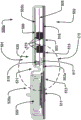
More specifically, fig. 1E through 1N illustrate a device 500 or an alternative device 500a, the device 500 and the alternative device 500a each generally having a component side or upper side 501, a patient side or circuit side 502, and one or more universal electrical layers generally identified by reference numeral 503. Here also an elongated strip layer or circuit layer 505 arranged in the common electrical layer. The circuit layer 505 may have electronic devices thereon and/or therein, see, for example, component 519, described further below. Fig. 1E and 1F, in certain non-limiting embodiments, show these elements, and some other elements that may be used with these elements, in moderate scale in a device that may be shown to be substantially transparent or translucent. Fig. 1E and 1F show two or more layers, typically one above the next, here comprising a first layer 503a, the first layer 503a being a flexible or flex circuit layer showing significant bending, here shown as an arch, as the first layer 503a may be intended for a subject user (generally identifying the user or wearer 1000 in fig. 1F). In this context, the second or intermediate circuit layer 505 is a relatively rigid sheet of material, and the second or intermediate circuit layer 505 is not bent or bowed or otherwise bent to more easily maintain electrical connections and/or circuit components attached to, in and/or within the layer. Herein, an optional third layer 503b is also shown above the circuit layer 505, the third layer 503b also being a flexible layer; herein, the third layer 503b has data communication capabilities via one or more data communication devices 506 (herein, via antenna 506).
Respective cross-sectional views of the devices 500 and 500a are shown in respective fig. 1G and 1H and 1I. Devices 500 and 500a also each have a top or external side 501, a patient side 502, and one or more universal electrical layers, generally identified by reference numeral 503, typically including an elongated strip layer or circuit layer 505 located in the universal electrical layers. In these embodiments, a stack of these two or more layers is shown, here three layers, one on top of the other, as shown. Adhesive layer 513 is shown in fig. 1H and 1I, with adhesive layer 513 omitted in the embodiment of fig. 1G for ease of displaying/viewing other operational portions as described below. On the side opposite the stack of these circuit layers are a battery 520 and a battery case or case 520 a. Other optional and/or preferred components are further explored/described below.
As a result of the removal of many electrical components from the bottom, a subject-facing layer (herein, layer 503a) is achieved, which subject-facing layer 503a remains extremely flexible, being able to accommodate a variety of body types, sizes and shapes, and body movements. Only a few components remain on this lower layer 503a, which are themselves typically the actual sensors in this embodiment. These components are ECG electrodes 508 and 509, PPG (photo-plethysmogram) device/sensor 511, temperature sensor 515 and microphone 516, e.g. a piezoelectric microphone. The signals received by these sensors can then be passed to the next layer 505 above it, i.e., the "floating" relatively rigid PCB, by the microconnectors 517, which are placed in such a way as to be mechanical hinge points to have electrical communication between them. In some embodiments, the processing electronics 519 may be provided to reside on the rigid PCB505, which may thereby increase solder reliability, and thereby increase reliability and robustness of electrical communication; this is why the electronics and/or processing components 519 have little movement relative to the PCB 505. In addition, removal of the electronic device 519, such as an IC, from the flexible layer 503a may remove or reduce the rigidity in or from the subject-facing layer 503a disposed below the more rigid layer 505.
In some embodiments, and as shown herein, above the rigid layer 505, another flexible layer 503b may be disposed. In some cases, this may be an antenna 506, such as a bluetooth antenna, connected to layer 505 by a micro-coaxial connector 518 placed near the hinge point 517 described above. The third layer 503b may be configured to be flexible to maintain the flexibility of the overall stack of three circuit boards.
The housing 530 is shown in fig. 1H and 1I because the housing 530 may be disposed on and include other portions. The housing 530 may be made of a pliable or flexible silicone, typically medical grade silicone, and may be a molded part to provide a shape substantially as shown. Also shown are pleats 531 or folds, creases or folds in such a housing 530; this corrugation allows for further bending movements, here near the center of the device, and/or near the connection of the rigid plate 505 to the flexible substrate 503 a. This connection region is shown and described in more detail in FIG. 1I et al, where FIG. 1I is generally an enlarged approximation of FIG. 1H taken near circle C1I of FIG. 1H.
In FIG. 1I, a host substrate 503a is shown with an adhesive layer 513. Attached to the substrate 503a is a rigid board 505, the rigid board 505 being connected to the substrate 503a through electrical/data connectors 517. General purpose electronics 519 are shown on both sides of the board 505; the two sides may optionally be used to maximize the use of real estate on the plate 505 while keeping the overall size, width, and length of the plate 505 relatively minimal. This is optional and in some embodiments only one side may be used. Also shown in fig. 1I for general reference are sensor assemblies 511 and 515, a battery 520, and a battery compartment 520a (which may take other forms, not shown) on substrate 503 a. The third layer, layer 503b, is shown housing antenna 506 and connected to PCB505 via connector 518. However, as introduced in fig. 1H, a better view of the folds 531 of the cover 530 is shown in fig. 1I, the folds 531 allowing a greater curvature of the substrate 503 a. In this context, it is more apparent that two gaps or hinges 503h and 513h are formed in the substrate 503a and the adhesive layer 513, respectively, each gap at the hinge being provided with flexibility. In a simple model or view, these gaps may be formed due to the lack of material at these points. (note that in the embodiments described herein, the adhesive may be formed from six layers strategically placed, and for the opposing gap/hinge 513h, only 1 or a few of the 6 layers may remain present at/at this point 513h, with a reduction in material being representative of this concept). Note that the gaps and adhesive are not shown in the alternative embodiment shown in fig. 1G.
Fig. 1J is a more schematic diagram showing some options, showing an alternative representation (dashed lines) of a gap/hinge 503h in the substrate 503a and a gap/hinge 513h in the adhesive layer 513. A representative sensor element, as herein, a temperature sensor 515 is shown as being schematically attachable to the substrate 503 a. A relatively rigid plate 505 is shown attachable to the flexible substrate 503a via a connector 517. The electronic components 519 are shown on the top/outer side of the board 505, with a dashed/optional representation of the second component 519 on the lower side of the board 505, which schematically shows the alternatives of these connections/configurations, the upper side being as optional as the lower side, although not illustrated as such herein.
FIG. 1K differs from FIG. 1J, although it is represented by adhesive removal and removal alternatives/dashed lines, with a more schematic representation. In a front view, the embodiment of fig. 1K shows a relatively unbent flexible circuit board 503 a. In contrast, the embodiment of fig. 1K1 shows the same assembly with a curved arrangement of the substrate 503 a. The curved arrows generally show movement. Fig. 1K1 illustrates a situation that may not be ideal depending on the type of connector 517. Preferably, a connector 517 is selected that can allow some rotational movement; however, the preferred embodiment will provide a robust secure electrical connection at 517. In fig. 1K1, some space is visible, which may indicate a disconnection; however, the objective is to demonstrate a connection device that, if available, can allow some relative rotational movement, but still continue to provide a robust electrical and/or data communication connection.
In another alternative, as shown in fig. 1L and 1L1, the flexible circuit board 503a may be configured to have a relative stiffness in the area under/near the connector 517, which may be a feature of the board 503a or may be imposed on the board 503a by the connector 517. In either case, this embodiment of a "Flexible Stack-Rigid Connector" may provide a relative correction to the embodiment of fig. 1K1, which shows that the Connector mating surface does not deform during bending as shown in the embodiment of fig. 1K 1. As shown in fig. 1L1, the device may be relatively more flexible in the regions generally identified as 503a1 and 503a3, and may be relatively more rigid in region 503a 2. In this embodiment, the connector itself has little movement. In fig. 1K1, the connector portion is slightly skewed, which may also occur, although it is more slightly skewed in fig. 1L 1; however, in many embodiments, connector 517 will have locking lugs to prevent any movement within the connector to keep all 60 pins in contact with each other. Some connectors found to meet certain preferences include 60 pin connector 517, female and male connectors manufactured by sammtech corporation (Samtech). Hirose is a manufacturer of coaxial connectors on/from the antenna 506 to the connector 518 (as in fig. 1H and 1I), where the mating coaxial connector 518 on the double-sided board 505 (also depicted in fig. 1H and 1I) may be provided by Amphenol.
As an annotation on the embodiments of fig. 1I-1L, the temperature sensor 515 (which may be an "insulated skin temperature sensor" in many embodiments) was found to be located with a more suitable deployment near the rigid portion of the stack and/or near the center of the area of the device. A location near the rigid portion may provide better, if not optimal, skin contact, while a location at the center of the area may allow for maximum distance from the edge in the x and y directions. In combination with the adhesive stack (which may serve as a thermal insulator in this application), the temperature sensor can be brought into thermal equilibrium with the skin quickly, thereby improving accuracy.
Fig. 1M and 1M1 illustrate "flexible microphones" that may be implemented herein. The microphone technology used herein may be a flexible piezoelectric strip 516, the flexible piezoelectric strip 516 may emit a voltage having a magnitude proportional to the amount of bending it experiences. A piezoelectric film 516 connected to the substrate 503a by an electrical connection 516a may be employed to allow the device to be sensitive in two band passes: 0 to 10Hz, and centered on a bandpass of 1100 Hz. The placement of the piezo 516 as shown in FIG. 1M is of interest. The piezo 516 may be placed on the patient side of the substrate 503a to straddle the hinge point. By placing a portion of the piezo in region 516b on the flexible hinge 503h and a portion of the piezo on the less flexible region 516c, the microphone 516 may be sensitive to relatively large chest movements occurring during breathing (in the 10Hz range), thereby producing breathing frequencies from ultra low frequency sounds. The portion above the less flexible portion is sensitive to sounds in the mid range of 1100Hz, producing breath sound data such as wheezes, air occlusion volume, etc. Since the hinge point is where the maximum bending occurs, the maximum possible voltage will be generated during the patient's breathing. The modulated voltage is then processed using DSP techniques to provide an accurate measurement of the patient's breathing rate and depth.
The description of antenna 506 is that antenna 506 may preferably be designed to fit, for example may be custom fit to fit within the housing of device 500/500 a. Antenna 506 may resonate at 2.4GHz with a minimum standing wave ratio and maximum forward power. To achieve this, the length, width and dielectric thickness of the active elements can be optimized in situ on the human body when the circuit board, silicone covering 530 and adhesive layer 513 are placed in place. A novel feature may be that the dipole antenna is generally made up of two elements (one passive and one active) of equal length at the resonant frequency. This embodiment of a dipole uses active elements at the resonant frequency, while the human body acts as a passive element.
Fig. 1N and 1N 1-1N 6 illustrate various external views of the device 500 or 500a, etc. FIG. 1N is a three-dimensional top view; fig. 1N1 is a plan view more specifically for the upper side 501, fig. 1N2 is a plan view for the patient side 502 of the lower side, fig. 1N3 is a first elevational side view, and fig. 1N4 is a second elevational side view. Fig. 1N5 is a front elevational view, and fig. 1N6 is a back elevational view.
Fig. 1N provides a three-dimensional top view of device 500 or 500a, etc., including optional third electrode 510, electrode extender 504, silicone cover 530, pleat 531, battery compartment 520, and removable battery compartment cover 533. The removable battery compartment cover 533 may be a rotatable friction fit type (or bayonet style) cap that allows the cap to be fixed in place relative to the battery compartment 520. In some embodiments, the removable battery pack cover 533 may have an unlock indicator 534 and a lock indicator 535, the unlock indicator 534 and the lock indicator 535 aligned with a reference mark 536 to assist the user in determining whether the removable battery pack cover 533 is more generally fixed in place relative to the battery pack and the device. Furthermore, in some embodiments, the battery compartment cover 533 may also have a handle 537 protruding from the surface of the battery compartment cover, the handle 537 may assist the user in turning (screwing or unscrewing) and securing the battery compartment cover. Optionally, the battery case cover 533 may also have one or more notches 538 to assist the user in rotating (screwing or unscrewing) the battery case cover. In some cases, the battery case cover may have a sealing material, such as silicon, rubber or other suitable material (not shown in the drawings), around the circumference of the underside of the cap to make the battery case waterproof and thus protected from external conditions.
Fig. 1N1 is a plan view of the upper side 501 of a device 500 or 500a, etc., including an optional third electrode 510, a flexible electrode extension 504, a silicone cover 530, a pleat 531, a battery compartment 520, a removable battery compartment cover 533, an unlock indicator 534, a lock indicator 535, a reference sign 536, a handle 537, and a recess 538.
Fig. 1N2 provides a plan view of the patient side 502 of the underside of device 500 or 500a, etc., including optional third electrode 510, flexible electrode extender 504, and silicone covering 530.
Fig. 1N3 provides a first elevational side view of a device 500 or 500a, etc., including an optional third electrode 510, a flexible electrode extender 504, a silicone cover 530, a pleat 531, a battery compartment 520, a removable battery compartment cover 533, and a handle 537.
Fig. 1N4 provides a second elevational side view of device 500 or 500a, etc., including optional third electrode 510, flexible electrode extender 504, silicone cover 530, pleat 531, battery compartment 520, removable battery compartment cover 533, and handle 537.
Fig. 1N5 is a front elevation view of a device 500 or 500a, etc., including an optional third electrode 510, a flexible electrode extender 504, a silicone cover 530, a pleat 531, a battery compartment 520, a removable battery compartment cover 533, and a handle 537.
Fig. 1N6 is a back elevational view of a device 500 or 500a, etc., including an optional third electrode 510, a flexible electrode extender 504, a silicone cover 530, a pleat 531, a battery compartment 520, a removable battery compartment cover 533, a battery compartment cover handle 537.
Fig. 1N7 provides a plan view of the upper side 501 of device 500 or 500a, etc., including optional third electrode 510, flexible electrode extension 504, silicone cover 530, pleat 531, battery compartment 520, removable battery compartment cover 533, unlock indicator 534, lock indicator 535, reference numeral 536, battery compartment cover handle 537, and notch 538.
Another alternative embodiment is shown in fig. 1W. Shown herein is a method of audio pick-up and bonding structures and/or reducing audio, audible noise or acoustic noise; in particular, but not limited to, for reducing audible noise in worn devices (fig. 1W). Applying an audio pick-up device or sensor or microphone or the like to a patient, the interaction between the pick-up sensor or similar and the skin, in particular the movement of the sensor relative to the skin, may cause unwanted noise to the sensor or the sensitive mechanical membrane of the sensor, if any, which may mask important or desired physiological sounds. This is even more evident on/in/when used with electronic amplification or other very sensitive audio sensors, which may be arranged to introduce noise.
Embodiments herein may relate to a removable double-sided silicone adhesive, in some embodiments, one or both sides are initially protected by a release liner. In such embodiments, one adhesive side is applied to the audio sensor and then the other side may be applied to the patient (the person to be monitored), so that at least some of the motion noise due to the motion of the sensor relative to the skin, and in other possible embodiments, all of the motion noise may be eliminated or significantly reduced.
In one or more primary embodiments, other adhesives are typically not included (e.g., no composite adhesive or no stacked composite adhesive, even typically no conductive regions or layers); however, in other possible embodiments, other uses are included with or including such other adhesives or adhesive portions, whether used with audio sensors or with wearable health monitoring devices having other sensors and/or electrodes, for example. In the primary embodiment of fig. 1W, the adhesive may typically be a single-sided, thin, double-sided silicone adhesive or tape. Typically, this may be a silicone adhesive approved or acceptable for skin contact, thereby eliminating mechanical noise. This may also and/or alternatively be applied to wearable devices by providing a relatively immovable or very limited movement coupling between the microphone and the skin, thereby reducing mechanical noise. In some embodiments, the silicone adhesive may be provided for one or more applications to a particular patient. Furthermore, in some embodiments, hair removal may not be required by selection of an appropriate adhesive.
In fig. 1W, for a specific first non-limiting example, in the wearable health monitoring device 100b, for example, a microphone or other audible, acoustic, or audio sensor 150 may be disposed on or in or otherwise operatively associated with the substrate 105 of the device 100b for final operational application to or association with a patient or other wearer (not shown in fig. 1W). Also shown is a dashed representation of an electrical/audio signal connection 151 for communicating sound data from the patient via the sensor or microphone 150 to a central data collection and/or communication device of the health monitoring device 100b (see other descriptions of optional alternative operational data acquisition and/or operational devices that may be disposed on the substrate 105 and used herein) for appropriate processing. The adhesive 113 is shown disposed over the acoustic sensor or microphone 150 (different from the description above) and is in operative relation to the acoustic sensor or microphone 150 (in this example, the adhesive is configured to be disposed over the other devices 108, 109, 110, and the substrate 105). The adhesive 113 will be exposed by removal of the release liner 114 (unlike the description elsewhere herein), as well as attached to the patient for final handling and collection of physiological signals or sounds such as heartbeats. The adhesive will function to isolate and/or maintain the operational setting of the device 150 relative to the skin and/or patient to eliminate and/or reduce movement of the device 150 and the resulting noise that would otherwise disrupt or potentially erase the sound or signal data of interest.
The specific use may be on a device 100b with one or more other sensors, electrodes and/or optical devices (transmitters and/or receivers) as shown, or the specific use may involve only an audio sensor or microphone. Use by either an adult or a child has the benefit of potentially enhancing the sensing and/or capture of the child's heartbeat.
Returning to the description of the other components, on the patient side 102, the ECG electrodes 108, 109, and 110 may be exposed for substantially direct contact with the patient's skin (although at least conductive adhesive may be applied therebetween); and/or, in many embodiments, the patient side electrodes 108, 109, and/or 110 may be covered by a conductive adhesive material as described below. The electrodes may be plated or may be of robust highly conductive material (e.g., silver/silver chloride) for biocompatibility and high signal quality, and may be strong in some embodiments, suitable for withstanding over about one thousand (1000) alcohol wash cycles between patients, for one non-limiting example. In some cases, these silver/silver chloride electrodes may be printed directly on the flexible circuit board or flexible printed circuit, while in other cases, the silver/silver chloride electrodes may be attached or secured to the flexible circuit board or flexible printed circuit as a separate and independent step in the manufacturing process. The pulse oximeter may be provided with windows or other communication channels or openings 111, 112 (fig. 1C), e.g., LEDs and sensors. Such openings 111, 112 (e.g., in fig. 1C) may typically be provided to optimize optical communication to or from the patient's skin. The non-limiting example in FIG. 1D illustrates an alternative arrangement of one or more light pipes 111a/112a (and 111b/112b), the one or more light pipes 111a/112a (and 111b/112b) being disposed closer to the electronic device 103 and/or connected to the electronic device 103. Various alternative arrangements may be used in the present invention, some of which are described further below.
In some embodiments, a sample of ambient light (LED off) may be provided and then subtracted from each of the pulse oximetry (ox) signals to cancel noise caused by sunlight or other ambient light sources.
The LED and one or more photodiode sensors may also and/or alternatively be covered with a silicone layer to remove any air gaps between the sensor/LED and the patient's skin. Some examples of this are given in fig. 1Q and/or 1S and/or 1T1 and/or 1T2, 1U1 and 1U2, respectively. Wherein silicone layers or coverings 121 and/or 121a and/or 121b and/or 121c and/or 121d are shown covering/surrounding the light pipes and/or sensors/LEDs 111c/111d/112 c. LED111c (one or more of fig. 1Q and/or 1S and/or 1T, 1T1, 1T2, 1U1, and/or 1U2) may be a red LED, LED111 d (one or more of fig. 1Q and/or 1S and/or 1T to 1U2) may be an Infrared (IR) LED, and device 112c (one or more of fig. 1Q and 1S and/or 1T to 1U2) may be a sensor. Alternative and/or additional LEDs may be provided; with respect to the first example, one or more additional or alternative color LEDs (not shown) may be provided, e.g., green LEDs (not shown) provided for additional and/or alternative functions as described further below, similar to those shown in fig. 1Q and/or 1S and/or one or more of fig. 1T-1U 2.
Other alternative LED and sensor arrays or arrangements are shown in fig. 1T and 1T1, where one or more LEDs are more centrally disposed within the epoxy/light pipe 121c on the substrate 105a and one or more sensors or photodiodes are more peripherally disposed. In fig. 1T, two LEDs 111c and 111d (other than for positioning/geometry, as opposed to LEDs 111c and 111d in fig. 1Q and/or fig. 1S) are shown to be relatively centrally located with respect to one or more sensors (i.e., two sensors or photodiodes 112c and 112d in the present invention). As with fig. 1Q and/or fig. 1S described above, LED111c may be a red LED, and LED111 d may be an IR (infrared) LED, and device 112c and/or 112d may be one or more sensors, in the present invention two sensors or photodiodes 112c and 112 d. In fig. 1T1, four LEDs 111c, 111d, 11le, and 111f (other than for positioning/geometry, as opposed to LEDs 111c and 111d in fig. 1Q and/or fig. 1S and/or fig. 1T) are shown to be relatively centrally located with respect to one or more sensors, i.e., four sensors or photodiodes 112c, 112d, 112e, and 112f in the present invention. For fig. 1Q and/or fig. 1S and/or fig. 1T as described above, LED111c may be a red LED, and LED111 d may be an IR (infrared) LED, and/or 111e may also be a red LED, and LED111 f may be an IR (infrared) LED, and devices 112c, 112d, 112e and/or 112f may be one or more sensors, i.e. four sensors or photodiodes 112c, 112d, 112e and 112f in the present invention.
In contrast to more conventional or relatively conventional approaches where an intermediate sensor or photodiode is surrounded by LEDs, placing the LEDs in a more centered manner in the locations of fig. 1T and 1T1, and surrounding those more centrally placed LEDs with the sensor or photodiode, provides a geometry that can be set to capture a greater percentage of emitted light emitted from the LEDs in some cases. In more conventional or relatively conventional geometries, substantially all of the emitted light that is directed away from the photodiode is wasted. In the geometry described in fig. 1T and 1T1, more light, possibly as much as nearly all of the emitted light is captured by the sensor or photodiode, or in some cases, much more efficiently than the pre-assumed capture efficiency. Fewer LEDs than conventional multiple LED integrated sensors may be required due to the higher light capture efficiency. This may help to significantly reduce power consumption and achieve similar or better measurement results. In summary, the geometry of the LEDs, such as the red and IR combined geometry described above, and the photodiode (or sensor) array are shown and described, which can allow a more concentrated light to enter the subcutaneous region of the subject (e.g., patient/infant/baby/mother/athlete). In some embodiments, the combination of LEDs and photodiodes/sensors may also be referred to as an efficient integrated sensor. This arrangement may be implemented to determine SpO2 (peripheral capillary oxygen saturation). Note that in some practical embodiments, the sensor shown in FIGS. 1T and 1T1 may be, for example, about 5mm2And the diameter of the outer circle containing the sensor and LED may be about 8mm, respectively. In some embodiments, a preferred distance of the center of the red LED light source to the center of the corresponding sensor may be set to 3.2mm, and a preferred distance of the center of the infrared LED light source to the corresponding sensor may be set to about 3.7 mm.
The silicone layer or covering 121/121a/121b/121c/121d/121e may reduce the loss of light reflected off the skin and thereby substantially increase the signal and reduce noise due to movement of the skin relative to the sensor. In certain embodiments, the silicone may be referred to as a light pipe, and in some cases the silicone may be a clear, colorless, and/or medical grade silicone. As described further below, the silicone layer or covering 121 and/or 121a and/or 121b and/or 121c and/or 121d and/or the lens surface 121e (abbreviated 121/121a/121b/121c/121d/121e in this application, but having the same meaning) may also/alternatively be referred to as a light pipe or lens 121/121a/121b/121c/121d/121e, depending on whether it is transmitting or receiving in reflection, or both, since they participate in or propagate in the light.
In one or more embodiments, the encapsulants and/or lenses 121/121a/121b/121c/121d/121e herein can be made from medical grade silicone having one or more of a clear, colorless, soft, low durometer character. An example of such a professional silicone used by the present invention is known as a "tacky gel" (several suppliers), and typically has an ultra-high viscosity adhesive preferably embedded on both sides. The low durometer silicone combined with the double-sided adhesive on the tacky gel can constitute lenses 121/121a/121b/121c/121d/121e that can be simultaneously conformable to the electronic sensor and the skin, and in some embodiments, exhibit reduced motion artifact characteristics by limiting motion between the skin-lens-sensor interface. The lens according to the present invention may also/alternatively be specially shaped so that it can be snapped between the layers of the composite adhesive strip (see, e.g., fig. 1D, 1P, 1R, and 1R1), and in some embodiments, the size of the opening (typically a rectangular opening) in the adhesive strip allows the lens to be slightly raised from the patient side of the adhesive strip by a raised portion (see further fig. 1S described below).
In FIG. 1S, another alternative silicone coating or encapsulant 121a embodiment for the LEDs and sensors 111c/111d/112c may include a convex lens at or near the outer surface 121b coating. In many embodiments, the outer surface and the lens are the same, and/or the lens may be defined by surface 121b of encapsulant material 121 a. This provides a structure and method for attaching the pulse oximetry LED emitters 111c/111d and one or more photodiode sensors 112c to the skin surface of the chest or forehead (e.g., a toddler or infant) or otherwise mounted on the patient or user's body.
More specifically, as described further herein, systems and/or devices 100 according to the present invention may utilize one or more LED emitters 111c/111d (and/or 111e and/or 111f) and one or more photodiodes of selected wavelengths. However, to maximize the coupling of the LED/sensor combination to the skin 1001 of the wearer 1000, the encapsulant and/or lens 121/121a/121b/121c/121d/121e constructed of optically clear, medical grade silicone can be molded over the LED/sensor combination or can be molded such that the encapsulant and/or lens 121/121a/121b/121c/121d/121e can be affixed in overlying relation to the LED/sensor combination 111c/111d/112 c. In many embodiments, such as in fig. 1S, the lens 121b may be partially spherical or may be hemispherical, although the lens need not be of such a shape. See FIGS. 1T 2-1U 2, below. Other shapes of bends are also useful. The bending may reduce the loss of skin contact when the device 100 is moved by the wearer's motion or otherwise. That is, movement of the wearer 1000 or movement of the device 100 relative to the wearer 1000 in fig. 1S may result in a similar rolling contact of the lens on or with respect to the skin 1001. Maintaining better skin contact means better data acquisition without interference and/or with reduced noise. In some embodiments, including those described above and below (although not shown directly therein, i.e., optionally included or not included therein), or as described below with particular reference to fig. 1U2, a thin silicone adhesive 113e may be used on and between the silicone layers 121/121a/121b/121c/121d/121e to help maintain skin contact with respect to the silicone encapsulant 121/121a/121b/121c/121d/121 e. See, for example, the description of fig. 1U2 below.
Furthermore, relevant to the function of maintaining contact is the light pipe effect, which can be achieved even if the LEDs and sensors of different heights communicate through a light pipe emanating from the skin and returning from the skin to the packaging material 121a/121c/121d/121e of the sensor with substantially little or substantially no air gap interference. Since there is no air gap in substantially constant contact with the skin from the emitter to the light conduit 121a/121c/121d/121e and/or the light conduit, which sometimes includes a curved surface, and through the light conduit 121a/121c/121d/121e, there is no or little or no air gap interference in the transmission into the skin and back through and from within the skin, and back to the sensor through the same light conduit material 121a/121c/121d/121e (transmission and reflection both refer to light propagation). This reduces inefficiencies caused by light waves scattering at the air gap interface (the air gap enables light to reflect from the skin or other surface). That is, the encapsulation of the LED and sensor provides no air gap to the skin and provides a light guiding effect to the skin, and the curved surface provides high quality low scattering into the skin and reception of reflections from the skin and bone. The light pipe and curved lens surface maintain continuous contact between the skin and the lens and reduce the loss signal generated by skin reflections. The signal-to-noise ratio is reduced and the quality of the data acquisition is improved.
It should be further noted that for curved lens 121b as selected in fig. 1S, the radius of the lens may be designed to maximize the content in (1) to (3). The height of the lens may be designed so that the lens can protrude above the composite adhesive 113 of the device 100 and into the skin, but not deep enough to affect the capillary bed, as this would result in poor data generation. Furthermore, there is no need and no need for a high degree of control over the bend radius and the angle of the LED light wave emission, since LEDs used to penetrate the skin (e.g., red and infrared and/or green LEDs) provide a wide array of emission angles, and thus a large array of reflected light waves will be focused back to the sensor through various curved surfaces. That is, the curved surface helps maintain contact during motion (accidental or intentional) and is less important for the angle of transmission through the skin and the angle of reflection back to the sensor. In other words, many different bend radii differ little in the effect of data/wave transmission and reflection; the wide angle emission of the LED thus takes into account the multiple radii case. However, this bending may be more restrictive to the process of maintaining contact due to movement of the device 100, e.g., a smaller degree of bending may not be easy to roll, and a small radius of curvature may render it impossible to transmit or receive an equivalent amount of data.
In some embodiments, a radius of curvature that has proven useful ranges between about 20 and 40mm for devices having LEDs and sensors in a compartment having dimensions of about 12.6mm by 6.6mm (radii of curvature of 20.34mm and 39.94mm have proven useful). It should also be noted that the LEDs may be located on one side or the other or two opposing sides, or possibly at four or more substantially equidistant points around the sensor, and may provide the desired results.
It should also be noted that pulse oximetry in the present application, as illustrated in one of any of the arrangements of fig. 1Q and 1S, and/or 1T-1U 2, may involve multiple light sources and/or sensors, e.g., typical pulse oximetry circuitry uses one light source (LED) at each wavelength (typically red, infrared and other wavelengths sometimes including green light or, for another example as described below, a long term average of red/infrared wavelengths). However, the apparatus and/or methods of the present invention may use multiple light sources within each wavelength. This may allow interrogation of a wider area of the capillary bed located on/in the patient/wearer in order to reduce the effect of local motion artifacts. Similarly, multiple sensors may be used for the same or similar purposes or advantages.
Furthermore, the combination of right leg actuation and/or proxy right leg actuation with pulse oximetry may provide additional advantages. Right leg circuitry for the chest or forehead or other electrode locations, proxy right leg and/or right leg drive may remove common mode noise and power line noise that would/might otherwise be capacitively coupled into the pulse oximetry sensor and attenuate the effects of noise generated therein. The combination of right leg actuation and/or proxy right leg actuation with improved pulse oximetry with the lens depicted in fig. 1S and/or the light pipe used in any one or more of fig. 1Q and/or 1T through 1U2 can significantly attenuate such noise and thereby enhance the quality of data acquisition. For the drive electrodes, see further details below.
Thus, the arterial blood oxygen content can be measured using optical signals (sometimes also referred to as heartbeat optical signals), typically from red and infrared pulse sources, which exhibit different optical absorptions depending on the presence or absence of oxygenated hemoglobin. In general, the transmission system is used with a light source and an optical detector. In many embodiments, as described below, a light pipe may be employed that encapsulates one or both light sources and one or more sensors, and in particular a sensor that may be encapsulated by a light pipe (meaning substantially without gaps) may be used to provide one or both of: increased light emission efficiency to the skin and/or capture photons that would otherwise be lost.
In the present invention, reflective systems are typical, and these systems generally have some advantages, namely being less intrusive and potentially more portable. As described herein, such reflective systems typically employ red and infrared light sources and photodiode sensors or detectors, or various arrangements of these components. Also, as described, one embodiment/method employs one or more central large area photodiodes/sensors/detectors with one or more LED light sources, typically one or more red LED and infrared LED light sources adjacent to or surrounding the array of photodiodes. Also, as described, an alternative arrangement uses a central LED group of one or more light sources with one or more of each wavelength type (red, infrared, green, etc.) and uses a plurality of large area photodiodes or photosensors surrounding the central LED. Such an arrangement may use two or three or four such detectors around the LED to collect more light scatter from the LED through the skin and other tissue; see, for example, fig. 1T and/or fig. 1T 1.
Another alternative embodiment may employ structural enhancement of the light source and/or one or more photodiodes and/or the surroundings. Described first is one or more such enhancements provided with respect to the central LED arrangement described above, but may also be used with or with respect to the previously described central sensor arrangement below. The optical enhancement structure may provide minimal intrusion in the collection region and may reduce the photodiode area or reduce the number of photodiodes. Thereby potentially providing cost benefits and/or increased efficiency.
In fig. 1T2, 1U1, and 1U2, in the light pipe 121d, the central LED light sources 111c and 111d are isolated from the peripheral photodetectors 112c, 112d, 112e, and 112f on the substrate 105a by surrounding the blocking wall 122 (also here by alternative reference B1). An alternative outer barrier 123 is also shown surrounding the sensor area. The barrier wall 122 (or B1) and/or the wall 123 (or B2) are preferably opaque and/or reflective to red and IR (or use any other color or wavelength of light, such as green light, etc.) to prevent cross-talk between the LED and the sensor, i.e., preferably and/or desirably all of the light leaving the LED area enters the skin rather than some of the light directly entering the sensor. The preferred surface of the barrier is diffusely reflective (as opposed to generally relatively absorptive and/or specular gloss). One example may be transparent anodized aluminum. Another example is textured white paint. Operations are shown and described with respect to FIG. 1U1 and/or FIG. 1U 2; see below.
The shape and size of the wall 122 may be selected to be suitable for the shape and size of the LED light sources (here light sources 111c and 111 d). For example, as shown, the wall 122 may be circular, or may be a square or rectangular shape of the surrounding LEDs 111c, 111d or other shapes (not shown) (note also here that the wall 122 may include or surround more or fewer light sources). The width or thickness and material used for the barrier walls 122 may be variable or varied as needed or desired; in practice, the width may depend on the material and/or vice versa, as the relative opacity of any particular material may mean a smaller or larger width required to provide a particular level of opacity or relative diffuse reflectance. The particular wavelength of light (i.e., the type of light used) and/or the type of sensor and/or the relative and/or overall geometric relationship (sensor of light source, sensor of sensor, and/or light source of light) (source) may also be considered for use in and/or due to the relative size and/or material of opacity corresponding to the particular wavelength. There may be cases where: the relative thickness may have a greater relationship to the type of material of the wall or its opacity or relative diffuse reflectance. In some embodiments, the barrier/wall may be machined, anodized aluminum or other similar material, but other embodiments are plastic, such as molded plastic. For red and infrared use, one driving consideration may be that the material may preferably be opaque or reflective or diffusely reflective at 660 and 940 nanometers. Thus, in many cases, very thin aluminum meets this standard, and so does thicker plastics.
The choice of wall 122 will be primarily to provide an optical barrier to lateral propagation of emission from the LED (e.g., by far red or infrared light from, for example, LED11 lc/111 d), and the wall 122 is preferably horizontal or slightly above the optical exit of the LED. Preferably, the barrier wall 122 is also wide enough to prevent optical cross-talk of light or scattering material that never enters the skin, but not so wide that light from the LED scattered from the skin or other bodily material is prevented from reaching the photodiode detector outside the barrier wall.
An optional outer barrier wall 123 may also be employed. This outer barrier wall helps to collect light reflected from the patient or user. The size, thickness and material of the wall 123 may be similarly considered; the difference is mainly in the collection rather than the generation of light.
As described in fig. 1T 2/fig. 1U and/or fig. 1U 1/fig. 1U2, these developments may provide an improvement in external detectors by adding an optical collection structure that collects light from other areas where no detector diode is present and transmits or reflects a portion of the light to reach one or more detectors in this manner. Note that a central detector with other individually isolated light sources (not shown) may also have similar improvements.
A preferred structure of this type may include a transparent optical medium, in this case a light pipe material 121 d. The light pipe material may be molded into a shape that is within and/or around the relatively opaque barrier wall 122 (see, e.g., fig. 1U2, described further below), and that contains the sources 111c and 111d (and/or if others are present/when others are present) within the wall 122 and/or outside the wall 122 (between the wall 122 and the wall 123), the diode detectors 112c, 112d, 112e, and/or 112f (and/or if others are present/when others are present) embedded in the structure 121d with little or substantially no air gap between their detectors and the light pipe material. The detector devices 112c, 112d, 112e, and/or 112f may be molded into the optical medium, i.e., into the light pipe material itself, or may be pre-molded into cavities in the optical medium. This type of optical structure may be generally referred to as a "light pipe".
The shape of the light guide structure 121d and/or the surface 121e may be chosen in various ways depending on the number and size or shape of the detector diodes, and may be designed in such a way as to capture scattered light received from skin or flesh material not in direct contact with or above any detector diode, and to suppress the scattered light by total internal reflection and using a scattering reflective surface to redirect the light rays in a direction towards the one or more photodiodes. In this way, light lost in previous designs is captured by these devices of the present embodiments. In fig. 1T2 and 1U, the epoxy (light pipe) 121d is relatively flat, i.e., presents a relatively flat surface 121e that is neither concave nor convex, although it may have a curvature with one or more barrier walls. In fig. 1U2, a relatively flat or substantially flat surface 121e is also shown.
Also shown in fig. 1U2 is an optional thin silicone adhesive 113e on surface 121e, which thin silicone adhesive 113e can be used to relatively adhere the device to the skin (not shown here) to reduce movement of the device relative to the skin and enhance light emission and reception. If an adhesive is used, such adhesive may preferably be as thin as possible so as not to interfere with or provide refraction of the light wave passing therethrough. The thickness that can be handled in this way may be 0.2 mm. Also, it may be preferred that the adhesive have a similar index of refraction to the epoxy/encapsulant/light pipe 121/121a/121b/121c/121d/121 e. This choice of similar refractive index may contribute to or may be related to the thickness and material of the adhesive to be used. For example, a suitable refractive index similarity may result from or result in an operable 0.2mm thickness.
Some operational examples and/or alternatives are shown in fig. 1U1 and fig. 1U 2. In FIG. 1U1, where the light pipe is not shown for simplicity, lightwave emissions A, B and C from example LED111C are shown, although alternative examples of operation are possible. Wave a is a relatively direct emission that is unobstructed en route from the device to the skin (not shown), while wave B is shown as reflected from wall 122 (note that while waves are sometimes described, it is understood that any form of light energy herein, whether understood, for example, as or better understood, as emitted and/or collected photons or not; less preferred is wave C that is not reflected from wall 122; only the preferred form for highlighting most, if not all, of the waves exiting the LED that exit the LED area in a reflected manner and enter the user's skin (not shown here) is shown here; collection of light is shown with respect to exemplary sensors 112C and 112D, where in fig. 1U1 and 1U2, relatively direct waves D are shown, as these waves D may enter the sensor area and be captured by sensors 112C and/or 112D; reflected waves E are also shown, as wave E may reflect from walls 122 and/or 123. Note that the bottom or upper surface of substrate 105a may also be diffusely reflective of waves and help to eventually reflect these waves for sensor collection.
In fig. 1U2, the light pipe 121d is shown as an optional thin adhesive 113 e. The relative refractive indices of these materials may or may not affect or greatly affect the light passing therethrough. Similar refractive indices are preferred to minimize refraction. Even so, some refraction may occur, for example, by emitting light wave B in FIG. 1U2 and, for example, in collected waves E and F, F differs from E because F has no reflection of walls 122 and/or 123 of light wave E. Wave B appears as reflected and refracted. The choice of materials and the size and shape of the opposing structures may help manage the relative reflection and/or refraction to improve the efficiency of light emission and/or capture.
Turning to the adhesive alternative, fig. 1D provides a first example of an adhesive 113 used herein. The adhesive layer 113 is here a double-sided adhesive for application to the underside 102 of the device 100, and the second side may use a different type of adhesive for adhering to the skin of a human patient (not shown). Different types of adhesive materials may be used because the materials selected for the adhesive layer to be attached are different; typically, the material to be attached is a circuit or circuit board material for connection to the device 100, and a material to be attached to the patient's skin on the patient side (not separately shown). The protective backing 114 may be disposed on the patient side until it is desired to apply the protective backing to the patient. It should be noted that in many applications, the adhesive 113 is anisotropic in that it may advantageously conduct electricity in only a single direction or substantially a single direction, e.g., on an axis perpendicular to the surface in adhesive contact. Thus, a good electrically conductive electrical contact for signal communication can be made by/by such adhesive bonded to/by the adhesion layer on electrical contacts or electrodes 108, 109, and 110. It should be noted that a corresponding one or more optical apertures 111b/112b are shown in the example adhesive 113 of fig. 1D, the one or more optical apertures 111b/112b being used in conjunction with one or more light pipes 111a/112a in the layer 105 or through the layer 105 to convey light for communication of light data typically involved in pulse oximetry.
The adhesive may thus be placed or provided on the apparatus 100, in some embodiments, in a substantially permanent manner or with some replaceability. In certain embodiments, the apparatus shown in fig. 1A-1D and/or 1P may be reusable without (or in certain embodiments with) an adhesive. In many such cases, the adhesive layer 113 may be removed and replaced prior to each subsequent use, although the possibility of subsequent reuse of the layer 113 is not precluded. In a first or subsequent use of the replaceable adhesive layer 113, the user applying the apparatus to the patient may be, for example, a physician or technician or even the patient himself, who applies the conductive transfer adhesive 113 to the patient side 102 of the apparatus 100. The protective backing 114 can then be removed and the device adhered to the patient and activated.
After the device is applied to the patient/wearer, the device may be activated in a number of ways; in some cases, activation may be preset to not necessarily be a positive activation interaction from a doctor or patient, etc., as inertial activation and/or pulse oximeter activation may be substantially automatic, e.g., automatic upon receiving a sufficient minimum input (movement in the case of light reflection of blood flow by an inertial system or pulse oximeter); however, a button may be provided at the access point 106 or some other location proximate the electronics to allow the patient to start or stop the device, or to flag an event if desired. In an exemplary embodiment, the device may be worn for a period of time such as two weeks for substantially continuous data collection or at time intervals preferred and established in or by the system of the present application.
After the monitoring period is over, the physician, technician, patient or other person can then remove the device from the patient, remove the adhesive in some cases using alcohol, and establish a data communication connection for data transfer, e.g., using wireless communication or downloading data by plugging in/connecting a USB or similar data connector. The data can then be processed and/or parsed and, in many cases, immediately interpreted if desired. The on-board power supply may include a battery pack, and the battery pack may then also be capable of being recharged during the use interval, and in some embodiments, may be capable of being quickly fully charged in approximately 24 hours, after which the device may then be considered ready for the next patient or next use.
Certain alternative conductive adhesives may be used in the present application. Fig. 1O, O1, and 1P illustrate one such alternative conductive adhesive 113 a; a lower plan view in fig. 1O and an elevated side view in fig. 1O1 and 1P (connected to device 100 in fig. 1P). In certain embodiments, the conductivity may be anisotropic, as described above; primarily, if not entirely, in the Z-axis direction; the axial direction is perpendicular to the plane of the paper in fig. 1O (perpendicular to the plane of the paper inward and/or outward), and/or perpendicular or transverse to the long horizontal axis of the device 100 in the view of the embodiment of fig. 1O 1.
This particular exemplary embodiment includes a composite adhesive 113a, which composite adhesive 113a itself may include some non-conductive portions 113b and one or more conductive portions 113 c. In accordance with the adhesive 113 described above, the composite adhesive 113a may be a double-sided adhesive such that one side is adhered to the patient and the other side is adhered to the underside 102 of the device 100 (see fig. 1P) such that one or more conductive portions 113c may be disposed or placed at electrical communication and/or conductive contact points with integrated electrodes on the electronic monitoring device 100. Because the electrodes may function better with electrical isolation or insulation from each other, the adhesive may also be more specifically provided in certain embodiments described below with each electrode being in electrical contact or communication with the skin of the patient.
As shown in fig. 1O and 1O1, three isolated conductive portions 113c may be provided separately from each other by a non-conductive body portion 113 b. These conductive portions may then correspond to the electrodes 108, 109, 110 in the above example, and in particular as schematically shown in fig. 1P (note that the scale of the adhesive 113a is exaggerated and thus does not necessarily show an exact match with the electrodes of the device 100). In some examples, electrode region 113c may be an electrically conductive hydrogel that is or is not an adhesive, and in some examples, the electrically conductive hydrogel may be made of a tacky electrically conductive material, such as 9880 hydrogel adhesive by 3M company (3M company, st. paul, Minnesota). These areas 113c may then be isolated from each other by a non-conductive material 113b, such as 3M company 9836 tape or 3M double-sided transfer adhesive 9917(3M, st. paul, MN) or equivalent. The additional layer 113d, when used, may be 3M 9917 adhesive and may be bonded to 113b of 9836 material. These structures can provide the following effects: a low electrical impedance path in the Z-axis direction (perpendicular to the paper plane of fig. 1O and perpendicular/transverse to the paper plane in fig. 1O1 and fig. 1P) of the electrode region 113c is created, and a high electrical impedance path in the X/Y direction is created between the electrodes. (see fig. 1O, 1O1, and 1P; coplanar with the paper in fig. 1O, and horizontal and perpendicular to the paper in fig. 1O1, and 1P.) thus, the composite adhesive strip can ensure not only that the device is adhered to the patient, but that both or the three electrodes shown are conductively connected by the conductive portions of the adhesive strip, wherein the combination of the conductive and non-conductive portions can reduce signal noise and/or enhance non-noise characteristics. Electrode movement relative to the skin can cause noise; that is, electrodes that are electrically communicated/connected to the skin through the gel may cause noise due to movement relative to the skin. However, the portion of the conductive adhesive or adhesives that are connected to the electrodes in the composite adhesive and then substantially securely connected to the skin will keep the electrodes substantially fixed relative to the skin and thereby reduce or even eliminate movement of the electrodes relative to the skin. Removing this motion removes noise and thus provides a clean signal that allows monitoring of the heart P-wave, thereby increasing the likelihood of detecting arrhythmias that could not otherwise be detected. Further description is given below.
In some embodiments, an alternative connection and/or isolation structure 113d may be implemented in the manner shown in fig. 1O1 and/or fig. 1P to provide further structural and isolation separation between electrodes connected to device 100 on underside 102 (see fig. 1P). Although the connecting and/or insulating structure 113d is shown in a separated form in fig. 1O1 and/or fig. 1P, the connecting and/or insulating structure 113d in these views may be adjacent to the insulating adhesive 113 b.
Other alternatives related to adhesives may be used. In certain embodiments, the composite adhesive tape used may have features for reducing one or more motion artifacts. Typical ECG attachment systems use conductive gel on the electrodes. However, a hydrogel adhesive may be used herein, embedded in a continuous sheet of laminating adhesive covering selected areas or the entire footprint of the device. The strong adhesive properties of the hydrogel itself, together with the use of an adhesive to cover the entire covered area of the device, may ensure a strong bond between the device and the patient's skin. An alternative way of placing the device vertically on the sternum may help to reduce motion artifacts, with the result that motion artifacts of one or more of the ECG signal, the photoplethysmography waveform, and the oxygen saturation signal are reduced.
In certain embodiments, improvements to composite adhesives may include waterproof encapsulation of the hydrogel adhesive to prevent clipping of the signal amplitude due to ohmic resistance reduction. This also helps to prevent degradation of the hydrocolloid adhesive. In particular, as shown by the non-limiting alternative examples in fig. 1R and 1R 1; several layers may be used. Here, layer 1(113h) may be a hydrocolloid, which is an adhesive designed to make long-term skin contact by absorbing sweat and cells. Layer 2(113i) may then also be a layer designed for long-term skin contact, however, this layer 2(113i) isolates layer 3(113j) from contact with the skin. The smaller size of layer 2(113i) creates a gap between layer 1(113h) and layer 3(113 j). When layer 1(113h) and layer 3(113j) are joined together, a water-tight seal is formed around layer 2(113 i). This layer 2(113i) also isolates the hydrocolloid from the hydrogel to preserve the adhesive properties of the hydrocolloid. Thereafter, layer 3(113j) and layer 5(113l) are typically electrically isolated, water-resistant layers of double-sided adhesive type. These two layers encapsulate the hydrogel adhesive to prevent "shorting" as described below with respect to layer 4(113 k). Layer 4(113k) is a hydrogel adhesive, which is herein a conductive element. The three island-like regions of the hydrogel adhesive of layer 4(113k) must remain electrically isolated from each other. However, since the hydrocolloid in layer 1(113h) absorbs sweat, it is able to conduct electricity and may create "shorts" between the three islands of hydrogel adhesive in layer 4(113k), thereby reducing signal amplitude. However, this "short circuit" can be avoided by the above-described layer 3(113j) and layer 5(113 l).
In one or more additional alternative embodiments, the temperature may be a parameter determined therefrom. Which may be determined by a single sensor or multiple sensors as described herein. In some temperature embodiments, it will be sought to capture body temperature data for an infant or young child, or for other users, adults, or other users when used.
Temperature sensing of young children and/or infants may provide important assistance for health monitoring. Forehead or other use may be one such application. Another set of possible applications may include methods and devices for sensing the temperature of infants and mothers incorporated in so-called "kangaroo care". Evidence suggests that premature infants may benefit more than when placed in an incubator by sustained contact with the skin of the parent or mother. There is also evidence for lower mortality.
A device 100a for dual temperature sensing of an infant wearer 1000 as well as a mother wearer 1010 or ambient air 1011 is shown in the attached fig. 1V. Substrate 1105 is preferably a small flexible circuit board, which in some examples is about 20mm by 30mm in size. The board 1105 may be configured to contain circuitry 1103 for sensing relative X-Y-Z position and/or acceleration, for example, and/or to contain bluetooth or other wireless data/signal connections, and in many examples, replaceable and/or rechargeable batteries for extended use, for example, seven (7) days of continuous monitoring (alternatives to the circuit elements are not all separately shown in fig. 1V). The device 100a may be affixed to the infant using an adhesive, such as the composite adhesive 1113 shown in fig. 1V, which may further be a disposable, medical grade, double-sided adhesive, for example.
Each of the two temperature sensors 1111a and 111b may be disposed on one of the opposing sides 1101, 1102 of the device 100a and may be thermally isolated from each other and are typically waterproof, watertight or water-resistant. A thermally insulating layer or layer 1103a may provide thermal isolation for the electronics 1103 and/or the sensors 1111a and 1111 b. Another spacer 1103b may be disposed through the insulating/isolation layer 1103a to provide a path for electronic communication of the sensor 1111b to the electronics layer 1103. A silicone bead 1104 may be provided for insulation on the "infant side" 1102 and to help create a waterproof or water-resistant seal, and a silicone covering 1121 may provide a waterproof or water-resistant barrier on the "mother side" 1101. The sensor 1111b on the "mother's side" or on the top or outer side 1101 may be slightly raised relative to the cover 1121, with a thin/thinner covering material and/or silicone layer on the sensor 1111b on the "mother's side" or on the top or outer side 1101 in many embodiments. The sensor 1111a on the child side or patient side or circuitry side 1102 may be raised over or through adhesive and/or provided exposed or may also/alternatively be covered with a thin protective layer for water or water blocking.
The thermal insulation layer may provide one or two or more functions. It may be arranged to allow or allow the "baby side" sensor 1111a to reach equilibrium, thereby providing an accurate "core temperature" of the baby. It may also or alternatively isolate the temperature reading of the infant from the temperature reading of the mother or the environment. The "mother side" sensor 1111b does not have to provide the mother with an accurate core temperature. Generally, the function of the sensor 1111b is to distinguish whether the baby is in correct direct contact with the mother's skin; that is, relative measurements are provided for determining whether the infant is in relative contact with the mother or not in relative contact with the mother. If the infant is facing the wrong direction, but is still in the "nursing bag", the sensor will read the temperature of the environment. If the infant is outside the nursing bag, the sensor will read the indoor ambient temperature. The relative difference will be resolvable to provide an indication of where the infant is: whether in contact with or closely associated with (but not in contact with) the controlled "nursery bag" environment, or outside of the nursery bag in another environment that is removed.
An alert from bluetooth or otherwise wirelessly connected device may be used to alert the mother (or health care professional) that the baby is no longer in the correct desired position, or is no longer in the "nursing bag".
Certain alternative embodiments in the present application may include a right leg driven ECG circuit with one or more chest only electrodes "driven chest electrodes". In addition to the electrodes used to measure single or multiple lead electrocardiographic signals, device 100 may also use additional electrodes such as reference electrode 110 (see fig. 1A, 1C, 1D, and 1P) to reduce common mode noise. The operation of such an electrode may be similar to that of a conventional right leg drive electrode, but in this case the electrode may be located on the chest of the patient rather than the right leg of the patient, however the third/reference electrode may function as a leg electrode. The chest electrode may thus mimic the right leg electrode and/or be considered a proxy right leg drive electrode. A circuit or a portion of an overall circuit adapted to operate in this manner may include one, two, three or more of several amplifier stages for providing gain, and for filtering to ensure circuit stability and to tailor the overall frequency response. Such circuitry may be biased to control the common mode bias of the electrocardiogram signals. This driven chest electrode embodiment can be used in conjunction with a differential amplifier or a measurement amplifier to reduce common mode noise. In this case, the sensing electrode may be used as one of electrocardiogram electrodes. Alternatively, a single-ended ecg amplifier may be used in cases where the differential ecg signal is referenced to ground or some other known voltage.
The circuit or sub-circuit 200 shown in fig. 2A-2D using the transistor 201 may be such a circuit (also referred to as a module) and thus, as further shown in fig. 2A, may include a sense electrode 202, a drive electrode 203, and an amplifier 204. Both the sensing electrodes 202 and the driving electrodes 203 are placed on the chest of the patient so that both can be electrically connected with the patient. The amplifier 204 may include gain and filtering functions. The amplifier output is connected to the drive electrode, the inverting input is connected to the sense electrode, and the non-inverting input is connected to the bias voltage 205. The amplifier maintains the voltage of the sense electrode at a level close to the bias voltage. The electrocardiogram signal can then be measured using the additional electrodes. Indeed, where conductivity is enhanced by the use of anisotropic adhesive portions as described above, the use of this third electrode as a proxy right leg electrode (i.e. proxy right leg drive electrode) herein, as well or alternatively, can provide signal reception in otherwise unavailable situations. The clean signal may thus allow reception of cardiac P-waves, which increases the likelihood of detecting arrhythmias that cannot otherwise be detected.
Other alternative descriptions of circuitry include those shown in FIGS. 2B and 2C; in the non-limiting alternative shown therein, three adjacent electrodes E1, E2, and E3 may be used to acquire the ECG signal, with one electrode being used as the distal limb electrode of a conventional ECG monitor. Because the electrode-patient interface has associated impedances (Re1 and Re2), the current flowing through the interface will cause a voltage difference between the patient and the electrode. The circuitry may use a sensing electrode (El) to detect the patient voltage. Because the exemplary circuit node has a high impedance relative to circuit Ground (GND), only a minimal current flows through the electrode interface, which minimizes voltage drop between the patient and the node. The first of these alternative non-limiting circuits (fig. 2B) also includes an amplifier (Ul), the low impedance output of which (U1) is connected to a separate drive electrode (E2). The amplifier uses negative feedback to control the drive electrodes such that the patient voltage (measured by sense electrode E1) is equal to the bias voltage (V1). This may effectively maintain the patient voltage equal to the bias voltage without regard to any voltage difference between the drive electrode (E2) and the patient. The voltage difference can include a voltage difference caused by a power line sense current flowing (through Re2) between the drive electrode and the patient. This arrangement differs from a conventional "right leg drive" circuit in at least two respects: the drive electrode is placed on the patient's chest (rather than on the right leg) and the ECG signal is a single-ended (non-differential) measurement from the third electrode (E3). Since all electrodes are located on the patient's chest in the chest mounted example, a small device placed on the patient's chest may contain all electrodes needed for ECG measurements. One possible benefit of single ended measurement is that the gain and filtering circuitry (U2 and associated components (FIG. 2C)) required to determine the ECG signal requires fewer components and is less sensitive to component tolerance matching prior to recording (ECG output). the examples of FIGS. 2A, 2B, and 2C are non-limiting examples and are not intended to limit the scope of the claims thereto, and those skilled in the art may form other circuits with other circuit elements in accordance with the concepts of the present invention and within the spirit and scope of the claims of the present invention.
In many embodiments, the system of the present invention may include other circuitry that may work in conjunction with the ECG electrodes, which may therefore be accompanied by other sensors to provide a time consistent trajectory as described below: i) ECGp waves, qrs waves, and t waves; ii) oxygen saturation measured using pulse oximetry; and/or iii) xyz acceleration to provide an index of physical activity. Such circuitry may be applied to one or more of the following electrical specifications. The overall system may include a run-time duration of up to two weeks (or more) in some embodiments; and data is collected during this time. Certain embodiments may be adapted to provide up to and even over 1000 uses. Alternative means may include operational capability even after or during exposure to liquid or humid environments; water-resistant, waterproof, or watertight in some such examples; in some cases work well when fully submerged (in low salinity waters). Other embodiments may include fast data transfer, such as using HSUSB to transfer all data in less than about 90 seconds. A rechargeable battery pack may be generally used.
Another alternative embodiment may include an electronic "ground" in the device of the present invention that is integrally mounted on a flexible circuit board, and the ground plane function may be provided by a coaxial ground conductor adjacent to the signal conductor. The main role of this type of grounding system is to allow the device to have the flexibility required to fit and adhere to the skin. Note that this alternative embodiment is not depicted in the figures herein.
For electrocardiograms, EKG, or ECG, certain embodiments may include an input impedance of greater than about 10 megaohms; some embodiments may operate at bandwidths of 0.1-48 Hz; and the sampling rate of some embodiments is close to 256 Hz; and a resolution of 12 bits can be achieved. For PPG and pulse oximetry, the work may use wavelengths of 660 and 940nm, approximately 80-100 Sp oxygen saturation range, 0.05-4.8 Hz bandwidth, 16Hz sampling rate, and 12 bit resolution. For accelerometers, 3-axis measurements may be employed, and in some embodiments a 2G range, a 16Hz sampling rate, and a 12-bit resolution are used.
For pulse oximetry, then a removal option for PPG ambient light may be included. A method and circuitry for reducing errors caused by ambient light during pulse oximetry is described and one circuitry option is shown in fig. 2D. There is shown a related double sampling technique for removing the effects of ambient light, photo-detectors, dark current and flash noise.
The content schematically shown in fig. 2D may be used for the case where the noise signal may be measured first. The light source is turned off, switch S1 is closed, and switch S2 is open. This causes a charge proportional to the noise signal to be accumulated at C1. After that, the switch S1 is opened. Here, the voltage at C1 is equal to the noise signal voltage. The optical signal may then be measured. The light source is turned on, switch S2 is closed, and charge can flow through C1 and C2 in sequence. Thereafter, S2 is turned off and the voltage on C2 is maintained until the next measurement cycle, at which point the entire process is repeated.
If C1 is much larger than C2, then C2 will experience almost all of the voltage and the voltage on C2 will be equal to one or more noise free signals. Otherwise, the voltage on C2 would be the linear combination of the previous C2 voltage (p) and the noise-free signal (S): (C2 × s + C1 × p)/(Cl + C2). This has the effect of applying a first order, low-pass IIR discrete-time filter to the signal. If this filtering effect is not desired, the voltage at C2 may be discharged to zero before measuring the signal every cycle, so that the voltage at C2 remains only: (C2 xs)/(C1 + C2).
Such a circuit may use a transimpedance amplifier instead of a resistor R, a phototransistor instead of a photodiode, and a FET instead of a switch. The output may be followed by additional buffer stages, amplification stages, filtering stages and processing stages.
Some of the summarized methods may be understood herein with reference to fig. 3, although other summarized methods may be understood by and in accordance with portions of the remainder of the disclosure. The flow chart 300 in fig. 3 may illustrate certain alternatives; wherein the initial operation 301 may be the application of the device 100 to a patient. Indeed, this may include one or more of the above-described alternatives to adhesive application, either by/through the use of an adhesive such as 113 in fig. 1D, or by the adhesive in fig. 1O, 1O1, and/or fig. 1P. Thereafter, moving along flow line 311, as shown, data collection operation 302 may be performed. It should be noted that this may include continuous or substantially continuous collection, or intermittent or periodic collection, or even a one-time event collection. This may depend on the type of data to be collected and/or on other characteristics or alternatives, e.g. whether a long-term data volume is required for the ECG, or whether a relatively single data point is useful in some cases of pulse oximetry (sometimes a single saturation point may be of interest, e.g. if the comparison data shows a trend of a single saturation point over time, it is actually more typical if the single saturation point is significantly too low).
Several alternatives are then shown in the flow chart 300 of fig. 3: a first alternative may be to reach the data transfer operation 303 along flow line 312, after which the data transfer operation 303 may involve wireless or wired (e.g., USB or otherwise) data communication from the device 100 to a data analysis device and/or a data storage device and/or system (not separately shown in fig. 3, which may include a computing device, e.g., see fig. 4 or similar figures described below). This option is also evident; however, a first alternative may include reaching the data analysis operation 304 along flow line 313 to analyze the data for determining relative health and/or for condition diagnosis of the patient. A computing system, such as a computer (which may be of many types, hand-held, personal, mainframe, or otherwise, see fig. 4 and the description below), may be used to perform this analysis; however, sufficient intelligence may be integrated into the electronics 103 of the device 100 so that certain analyses may be run on or within the device 100. One non-limiting example may be a threshold comparison, such as for pulse oximetry, where an indication or warning may be activated entirely on or by the electronics 103 of the device 100 when a low threshold level (or a high pre-high threshold level in some examples) is reached.
A similar such example is that the alternative flow path 312a may consider which branch of its own two sections 312b and 312c to take. Following flow path 312a, and then in the first exemplary path 312b, skipping the transmit data operation 303 can be understood such that the analysis 304 can be achieved without a large transfer of data. This may explain on-board analysis, e.g., according to the above threshold example, or in some cases may include more detailed analysis according to the degree of intelligence integrated on or in the electronics 103. Another view is on how much transfer volume may be needed even with transfer operation 303; as this may include at one level from the patient's skin through the conductors 108, 109 and/or 110 through the lead 107 to the electronic device 103 for analysis of data at the electronic device 103. Of course, in other examples, the transfer may include off-board download onto other computing resources (e.g., fig. 4). In some cases, this off-board loading of data may allow or provide more complex analysis by using resources with higher computing power.
Other alternatives, when used, may relate primarily to the time and place of data storage. Due to the intelligence, some or no storage device or memory may be used in the on-board electronics 103 of the device 100 or by the electronics 103. If some storage device (whether few or many) is available on device 100, then following path 312a and through path 312c may be used to implement some data store 305. This may occur in many cases, even if not necessarily before transmission or analysis (note that for certain types of data, multiple paths may be taken in parallel at the same time, although this may not be at the same time or sequentially (e.g., paths 312b and 312c need not be taken entirely independently of one another), so that storage and transmission or storage and analysis may occur without necessarily requiring any particular operation to be completed before another operation is started or performed). Accordingly, flow path 315a may be followed after (or during) storage 305, such that the stored data may be transferred to operation 303 via path 315b and/or to operation 304 for analysis via path 315 c. In this storage example (which may also be an on-board storage example in many cases), data can be collected and subsequently stored in local memory and later unloaded/transmitted to one or more robust computing resources (e.g., fig. 4) for analysis. Generally, the process may include long-term data collection, for example in the form of days or weeks or even longer, and thus may include remote collection when the patient is away from a doctor's office or other medical facility. Thus, data can be collected from the patient in the real world environment in which the patient is located. Thereafter, after collection, the data can be transferred from the storage device on its device 100 back to the desired computing resource (e.g., fig. 4), and this transfer can be wireless or wired or a combination of both, such as connecting to a personal computer using bluetooth or WiFi (one example in fig. 4), which can then transfer the data over the internet to the designated computer for final analysis. Another example may include connecting to a computer via USB, the connected computer may be a PC or host (fig. 4), and may be a patient computer or a doctor computer for analysis.
If there is little or no storage or memory resident on device 100 (or, in some examples, there may even be a large amount of resident memory available), then shortly after collection, it may be necessary or desirable to transfer and later store the data (see path 313a after operation 303), and/or transfer and analyze the data (see paths 312 and 313), or both. If path 313a is used, then more typically, the data storage device may be located off-board (although on-board memory may also be used) in or on a computing resource (not shown in FIG. 3, but see FIG. 4 below), and then any of paths 315a, 315b, and 315c may be used.
One feature of the present invention may include an overall system that includes one or more devices 100 and computing resources (see, e.g., fig. 4) that are onboard or independent of the devices 100, such as in a personal or mobile or handheld computing device (generally given by fig. 4), that also provides the ability for a physician or doctor to have immediate indoor analysis capabilities and present collected test data. In some embodiments, this will allow field data analysis by the device without using third parties for data extraction and analysis.
Alternative embodiments of the present invention may thus include one or more hardware and software combinations for multiple alternative data source resolutions. As indicated above, the device 100 of the present invention includes hardware that monitors one or more different physiological parameters and subsequently generates and stores relevant data representative of the monitored parameters. The system then includes hardware, software, and computing resources for processing therein (shown generally in fig. 4), such as the device 100 and/or components thereof. The system then includes not only data collection, but also interpretation of the data and related content.
For example, an electrocardiogram trace showing ventricular arrhythmias during intense exercise may be resolved differently from the same arrhythmias during rest. The blood oxygen saturation, which varies greatly with movement, can particularly indicate a much more severe condition than at rest. More combinations of four physiological parameters are possible and the ability of the software of the present invention to display and highlight possible problems will greatly assist the physician in making the diagnosis. Thus, the system described in the present invention is able to provide beneficial data parsing.
Certain features that can help achieve this can be included in one or more of operations 303 and 304 of fig. 3, where data collected on device 100 can be more easily transmitted/sent to a computing resource (again, may be onboard device 100 or independent of device 100, such as shown in fig. 4). For one example, when a patient to whom the device has been applied (operation 301) returns to the physician's office after a testing phase in which data is collected (operation 302), the device is connected to the office via one or more data transfer alternatives, for example via USB to a computer (Windows or Mac) in the office (see generally fig. 4 and the description of the invention), allowing for immediate analysis by the physician during the patient's wait (note that the device 100 may first be removed from the patient or may remain on the patient in the course of transmitting and analyzing to determine if more data is needed). In some embodiments, the data analysis time may be relatively short, in some embodiments about less than 15 minutes, less than 10 minutes, and less than 5 minutes, and may be accomplished by using a User-friendly GUI (graphical User Interface) to guide the physician through the analysis software.
The analysis/software package may be arranged to present the results to the physician in a variety of formats. In some embodiments, an overview of the test results may be presented with or in place of more detailed results. In either case, a summary of the detected abnormal conditions and/or patient-triggered events may be provided as part of the overview and/or as part of a more detailed presentation. Selecting a single abnormal condition or patient triggering event may provide the desired flexibility to allow the physician to view additional details, including source data from the ECG and/or other sensors. The software package may also allow for printing of the data and storing the data with annotations in an industry standard EHR (electronic health record) format.
In one embodiment, patient data may be analyzed using software having one or more of the following specifications. Some alternative capabilities may include: 1. data acquisition, namely loading a data file from equipment; 2. data formatting, i.e., formatting source data into an industry standard file format (e.g., aacg (xml), DIC0M, or SCP-ECG) (note that such data formatting may be part of the acquisition, storage, or analysis, or may be a conversion from one format to another (e.g., data may be better stored in a compact format, which may require conversion or other decapsulation for analysis)); 3. data storage (stored locally, in a clinic/medical facility, or, for example, in the cloud (optionally and allowing for offline portable browser-based rendering/analysis)); 4. analysis, which may include, for example, noise filtering (high-pass/low-pass digital filtering), among others; and/or QRS (heartbeat) detection (which in some cases may include Continuous Wave Transform (CWT) for speed and accuracy); and/or 5, data/results presentation, which may include one or more Graphical User Interfaces (GUIs), more particularly with a summary of the summary and/or gross statistics and/or exception summary of one or more patient-triggered events; additional levels of detail are presented: one or more strip views of anomalous data of blood oxygen saturation, pressure correlation, etc. of an event (before and after); and/or allow the caregiver to bookmark/annotate with events and/or printing capabilities.
Additionally, in an alternative combination of hardware and suitable software packages: (i) a software package on one device may be adapted to store measurements of data signals acquired from one or more EKG/ECGs (right leg and/or p-wave, qrs-wave and/or t-wave), or oxygen saturation measurements, or x-y-z acceleration measurements in a time consistent manner such that a physician may access a temporary history of measurements (i.e., maintaining intervals of 1 to 2 weeks in some examples), which may provide useful information about patient activity level before, during, and after the occurrence of a cardiac event; (ii) one alternative is to alternatively manage the real-time transmission of real-time measurement parameters to nearby base stations or repeaters, and/or (iii) the off-device ECG analysis software is intended to identify arrhythmias.
The software may be industrial licensing software provided by a third party or data specifically adapted to be generated, transmitted and/or received from the wearable device 100 of the present invention. The FDA510(k) was considered to be preferred during the entire testing procedure using the standard (MIT-BIH/AHA/NST) (Massachusetts Institute of Technology-Beth Israel Hospital/American Heart Association-Noise Stress Test, Massachusetts Institute of Technology-Israel Hospital/American Heart Association-Noise pressure testing) arrhythmia database. Such software may be adapted to allow one or more of the following: automatic ECG analysis and interpretation, QRS detection and measurement, QRS feature extraction, classification of normal and ventricular abnormal heart beats, heart rate measurement, measurement of PR and QT intervals, and beat rhythm interpretation by providing callable functions for ECG signal processing.
In many embodiments, the software may be adapted to provide and/or be arranged to be capable of providing one or more of the following measurements:
table 1:
1. heart rate minimum, maximum and mean
QRS duration mean
Mean value of PR intervals
Mean value of QT interval
Mean value of ST deviation
And, may be adapted to identify a wide range of arrhythmias, such as given by:
table 2A:
1. sinus rhythm
2. Sinus rhythm + inferior vena cava diameter
3. Sinus bradycardia
4. Sinus bradycardia + inferior vena cava diameter
5. Sinus tachycardia
6. Cardiac arrest
7. Unclassified heartbeat rhythm
8. Artifacts
The first set of 8 arrhythmia types given above can be identified even without discernable P-waves. These types of arrhythmias are typically identified by existing products in the outpatient monitoring market provided by the devices, systems and methods set forth in this study.
The second set or group of arrhythmias described below may require a P-wave that is discernable and measurable. Certain embodiments of the present invention may be adapted to be able to detect and identify this P-wave, as the device 100 may be able to detect P-waves based on the intensity of the P-wave or the physiological condition of the patient as affected by the location of the device 100, as described above.
Table 2B:
9. atrial fibrillation/tremor peripheral vascular resistance (slow)
10. Mechanical valve of atrial fibrillation/tremble heart (Normal frequency)
11. Atrial fibrillation/fibrillation ventricular repeat response (Rapid)
12. First-order atrioventricular block + sinus rhythm
13. First-order atrioventricular block + sinus tachycardia
14. First-order atrioventricular block + sinus bradycardia
15. Second-order atrioventricular block
16. Triple atrioventricular block
17. Premature atrial contraction
18. Ventricular tachycardia
19. Premature ventricular contraction
20. Room connection
21. Room bigeminal
22. Room triple
23. Ventricular self-rhythm
24. Ventricular tachycardia
25. Ventricular tachycardia
Additionally, in an alternative software implementation, some sample screenshots are shown in FIG. 5. A first such alternative is shown in fig. 5A, which is an example screen shot showing ECG and oxygen saturation data obtained by using a block device such as device 100 of the present invention. Here a very clean signal is shown (the data is not filtered or smoothed). Different p-waves are also shown (3 of which are shown as examples with arrows). P-wave detection is crucial for the detection of ECG abnormalities. The oxygen saturation measured using pulse oximetry is shown in the bottom graph. This data is acquired by a device on the chest and is time-aligned with the ECG data.
Another alternative, which is an example screenshot of the analysis software, is shown in fig. 5B. This is an ECG data sample obtained from the recording 205 of the MIT-BIH arrhythmia database. As analyzed by the system of the present invention, we can see in the five (5) abnormal case types (more normal sinusoidal rhythms) of the event occurrence summary list (top left). The list also shows the number of occurrences of each abnormal condition, the total duration of the abnormal condition in the entire ECG, and the proportion of time the abnormal condition occurred in the entire ECG. To view the specific case of each abnormal case, the user double clicks on a specific row in the event occurrence summary list, as shown in FIG. 5C.
As previously described, fig. 5C is an example screen shot illustrating a particular case of ventricular tachycardia. The ECG graph automatically navigates to a particular instant of the ECG waveform and marks the beginning and end of the event. More detailed data about this particular event is shown in the occurrence details: HR average, HR maximum, etc. during the event. To illustrate an example of another abnormal situation in this ECT, the user may click on the Premature Ventricular Contraction (PVC) line of the event occurrence summary, as shown in fig. 5D.
As previously described, fig. 5D is an example screen shot illustrating a particular case of a premature ventricular contraction. The figure shows the occurrence of PVC. The start time list (top middle) shows all occurrences of a PVC in this ECG and lists the start time for each occurrence. In this case, the user can click on a PVC starting at 00:15:27 (11 th occurrence). The ECG plot automatically reaches this point in time to show and indicate the PVC condition in the waveform. Since there were 3 cases of PVC during this time period, all 3 occurrences were marked.
As noted above, in one aspect of the inventive result, ECG signals collected in time correspondence with pulse oximetry signals may be used to reduce noise in the pulse oximetry signals and allow for the calculation of oxygen saturation values, particularly in environments where the sensors of the pulse oximetry data are located on noise prone locations such as the patient's chest. In certain embodiments, this aspect may be achieved by: (a) measuring electrocardiogram signals of a plurality of heartbeats; (b) measuring one or more pulse oximetry signals during a plurality of heartbeats such that the electrocardiogram signal and the one or more pulse oximetry signals during the one or more heartbeats coincide in time; (c) comparing a portion of the electrocardiogram signal that is consistent in time during the one or more heartbeats with the one or more pulse oximetry signals to determine a constant component and a dominant periodic component of each of the one or more pulse oximetry signals; and (d) determining oxygen saturation from the constant component and the primary periodic component of the one or more pulse oximetry signals. The measurement of the ECG signal and the pulse oximetry signal may be accomplished by embodiments of the device of the present invention. In particular, the pulse oximetry signals may be reflected infrared signals and reflected red light signals collected by the photodetectors in the device of the present invention. Alternatives may include other colors, such as green light in addition to or in place of one or both of red and infrared. Such alternatives are described further below.
The interval of the pulse oximetry signal corresponding to the heartbeat may be determined by comparing the signal to a time-coincident ECG signal. For example, and not intended to be limiting, successive R-wave peaks of a time-coincident ECG signal may be used to identify such intervals, although other features of the ECG signal may be used for identification as well. Once such an interval is identified, the values at the respective times within the interval may be averaged to reduce signal noise and obtain the number of signal values recorded in one interval for the constant component (sometimes referred to as the "DC component" and the primary periodic component (sometimes referred to as the more reliable value of the "AC component")) of the pulse oximetry signal (e.g., Warner et al, anesthesiology, 108:950-, signals from one or more heartbeats or intervals may be analyzed; in other embodiments, signals from multiple heartbeats or intervals may be analyzed; and in some embodiments the plurality of heartbeats or intervals range from 2 to 25, or from 5 to 20, or from 10 to 20.
As described above, pulse oximetry methods measure a photoplethysmogram (PPG) signal at red and infrared wavelengths. Direct Current (DC) or average is estimated and subtracted, and Alternating Current (AC) or pulse signals are estimated and/or averaged. A linear regression between the two signals can be used as described below. However, performance is limited due to the presence of similar noise in both the red and infrared signals. Using green light ( 550nm) is more resilient to motion noise,since this light is more absorbed by blood than by water or other tissue. However, the difference between oxygenated and deoxygenated blood in the green region of the spectrum is much lower than in the red region of the spectrum. In one alternative, the green PPG signal (or long-term average of red/infrared (see below)) may be used to determine the shape of the pulse signal. Any number of weighted averages of different wavelengths (such as green, red, and infrared) can be used to estimate the shape of the pulse waveform.
In other alternative embodiments, a linear regression algorithm may be used to calculate oxygen saturation. Likewise, one or both of the patient's ECG signal and/or green light (or other color) LEDPPG signal may be used. With respect to the first example, an ECG signal may be used to determine when a heartbeat occurs. The heartbeat position allows an associated time mean to be found for each of the two photoplethysmogram signals. A linear regression of the overall mean may then be used to determine a linear gain factor between the two signals. The gain factor may be used to determine the oxygen saturation of the patient.
In the alternative and/or additionally, if green light is used (ii) ((iii)) 550nm) performing a photoplethysmogram (PPG) when using green light (PPG)
 550nm), the PPG signal may be used to determine the shape of the pulse signal. This low noise signal can then be used as an independent variable for the linear regression of the red and infrared signals. The ratio of these two regression results is an estimate of the correlation between the red and infrared signals. Noise can be reduced by taking an overall average over multiple heartbeats as disclosed herein (e.g., see description of frames below). In addition to or instead of using the ECG signal to determine the heartbeat time, a green light wavelength PPG signal may be used. Alternatively, any number of different wavelengths (such as green)A weighted average of the light, red and infrared or long-term average of red/infrared (see below)) may be used. It is possible to detect and remove abnormal heart beats by discarding heart beats that are less correlated to the estimated overall mean than other heart beats, or by estimating the noise and weighted heart beats from high noise regions to be smaller, so that the overall mean is improved. Noise can also be improved by longer averaging periods.
As such, a method for health monitoring may be included, the method comprising: (a) determining when a heartbeat occurs from one or both of the user's ECG signal and/or the first photoplethysmogram, PPG, signal and/or the weighted wavelength combination; (b) time averaging the first photoplethysmogram, PPG, signal to generate a first pulse shape template or data set; (c) time-averaging each of two additional photoplethysmogram signals related to the heart beat position; one of the additional signals is a red light signal, and the other additional signal is an infrared signal; (d) generating an overall mean value for each of the red and infrared signals; (e) comparing each of the red and infrared ensemble means to a first pulse shape template or data set; (f) using a linear regression of each of the red and infrared ensemble means for comparison with a first pulse template or data set to determine a linear gain factor between the two signals; and (g) determining the patient oxygen saturation from the gain factor.
In a similar view, a method for determining pulse oxygenation may be included, the method comprising: (a) detecting the heartbeat by using ECG, using green light, or using a weighted combination of wavelengths; (b) generating one or more first pulse shape templates or data sets representing a first pulse shape, including using a green light wavelength, a green light ensemble mean over about the same amount of time for red or infrared, a plurality of wavelength ensemble means over about the same amount of time for red or infrared, or a plurality of wavelength ensemble means over a span of significantly greater amount of time than for red or infrared; an ensemble mean giving the shape of the heartbeat can be used; or a long-term average of individual wavelengths of any color; (c) obtaining a red pulse shape template or dataset representing the same term and an infrared pulse shape template or dataset representing the same term, and comparing each of these with the above first pulse shape; and (d) correlating via linear regression between the red ensemble mean with the first pulse shape template or data set and the infrared ensemble mean with the first pulse shape or data set, where the ratio of these correlations is then used as an Alternating Current (AC) ratio for oxygen saturation.
In certain embodiments, the pulse shape template or data set may also be similar to the reference frame template described herein, as the pulse shape template represents a long-term overall mean of the PPG signal. However, the difference is that the reference frame template described herein is specified elsewhere for pulse transit time, while in this specification relating to the first pulse shape or data set, the reference frame template is used for oxygen saturation.
Although the first method may be a method using green light for heartbeat detection, other methods are possible in which an ECG is used for heartbeat detection. Further, alternatives include green light or long red and infrared means being used for the first pulse shape, and shorter red and infrared are used for oxygen saturation compared to the first pulse shape. It may be helpful to understand: the long red and infrared mean values for the first pulse waveform shape (or data set) are correlated with the relatively shorter red/infrared signals for oxygen saturation measurement. Because the desired shape changes more slowly than the oxygen saturation, a long mean can be used for the shape, while still using a shorter mean (and thus faster response time) for the oxygen saturation portion.
It should be noted that green light has been found to be preferable because it has a high signal-to-noise ratio; the pulse signal is strong relative to other possible motion noise. However, other wavelengths may be used instead of green light, i.e. green light may be replaced by other colors in the spectrum of light, it being understood that some colors will perform better or other colors perform less well in signal to noise relationships. It should be noted that other colors can be used herein, even if they do not have the desired signal-to-noise ratio. Similarly, red and/or infrared wavelengths are preferred because red and/or infrared have been found to provide better relative reflectance for a particular oxygenation of hemoglobin blood in a test subject. Each of the oxygenated blood reflects a relatively effective amount of red light, and the deoxygenated blood reflects a relatively effective amount of infrared IR light. Other colors can be used to replace red and infrared light altogether, although other colors have less (or more) effectiveness in certain applications. It should also be noted that, as understood in the art, whenever light of any particular color is described, some discrete wavelengths may be understood to fall within such a definition, and the utility may fall within or outside of that definition, although preferably distinguished by a general color. Thus, colors other than green or red or infrared are understood to be used, and/or such color selection may be limited only by minimal effectiveness in signal-to-noise ratio and/or oxygenation-related reflectivity or other utility.
The ECG data and the green PPG data (or the like) or the long-term average data of red/infrared (see below) can be recorded in temporal correspondence with two or more photoplethysmograms with different light wavelengths. The heartbeat is detected in an ECG signal or a green PPG signal. These heartbeats allow the definition of 'frames' of photoplethysmogram data in the time between two adjacent heartbeats. Two or more of the frames may then be averaged together at each point in time to create an averaged frame for the time interval. Since the photoplethysmogram is correlated with the heartbeat, the photoplethysmograph signal is enhanced by this averaging process. However, any motion artifacts or other noise sources that are not temporally related to the heartbeat are eliminated. Thus, the signal-to-noise ratio of the average frame is typically higher than the signal-to-noise ratio of the individual frames.
After the average frame has been constructed for at least two photoplethysmographs of different light wavelengths, a linear regression method can be used to estimate the gain between the two average frame signals. The gain value may be used to estimate blood oxygen saturation information or other components present in the blood, such as hemoglobin, carbon dioxide, or others. To this end, the process may be repeated for additional and/or alternative wavelengths of light.
An exemplary/alternative method of the present invention may include determining the gain between particular and/or independent signals, if/when available, such as determining the gain between red and infrared and/or green frame signals. The gain may be first found by averaging the two frames together. This may result in a noise reduction of the signal. The gain is found by performing a linear regression of the relative bound red light and the relative bound infrared and then taking the ratio of the two results; or by performing a linear regression of red versus green combined and infrared versus green combined and then taking the ratio of the two results; or by performing a linear regression of red versus green and infrared versus green, and then taking the ratio of the two results; or by performing a linear regression of the green light combined with each of the red and infrared and using the ratio of the two results to find the gain.
Another method involves selecting possible gain values, multiplying the gain values by the average frame signal, and determining the residual error of the average frame with respect to different wavelengths. This process may be repeated for a plurality of potential gain values. Although simple linear regression finds the global minimum gain value, the method can also find the local minimum. Thus, if a global minimum can represent a correlation caused by motion artifact, venous blood motion, or another noise source, the global minimum can be ignored and a local minimum can be selected for replacement.
Yet another approach uses an ensemble average of red and/or infrared signals over a longer time to determine the pulse waveform shape, and then adjusts the shorter time average signal to that waveform shape. Basically, the green light signal or the ECG signal described above can be replaced with a long term average of red/infrared.
As described above, the patient-wearable device of the present invention for implementing the above aspects is particularly useful for monitoring oxygen saturation in noisy areas of such measurements, e.g. such as with significant local skin movement in chest locations.
One embodiment of the above-described aspects of the present invention is illustrated in fig. 6A-6C. In fig. 6A, curve a (600) shows the output of the Infrared (IR) reflection of the photodiode of the device of the present invention as a function of time, and curve B (602) shows the output of the photodiode of the device as a function of time. In certain embodiments, red and infrared LEDs are alternatively used to illuminate the skin to generate signals collected by the same photodiode. In fig. 6B, the time-synchronized (i.e., time-consistent) ECG data shown by curve C (604) (or alternatively/additionally, the green PPG data or the long-term average of red/infrared as introduced above) is added to the graph of fig. 6B. The peaks in the ECG data (e.g., peaks 606 and 608) (or long term averages of green PPG or red/infrared data, see above) may be used to define frames or intervals of pulse oximetry data. Additional consecutive frames or intervals are indicated by 612 and 614, and other frames are determined in a similar manner. According to this aspect, pulse oximetry data from a plurality of frames is collected. The modulus values of the multiple frames may vary widely depending on the particular application. In some embodiments, the plurality of frames collected ranges from 5 to 25; in one embodiment, the plurality of frames is from 8 to 10 frames. Typically, frames or intervals of pulse oximetry data contain different numbers of signal samples. That is, the output of the sensor may be sampled at a predetermined sampling rate, for example 32 samples per second. If the time between ECG (or green PPG or red/infrared long term average) peaks changes, the number of samples per frame will change. In one embodiment, the feature in the ECG (or green PPG or red/infrared long term average) data that serves as the starting point for a frame is selected such that the associated peak in the pulse oximetry data is located approximately at the middle or center of the frame, after which a predetermined number of signal samples are recorded for each frame. Preferably, in this embodiment, the predetermined number is selected to be large enough to ensure that the peak of the pulse oximetry signal is substantially an intermediate frame. Sample values greater than a predetermined value corresponding to the above time point are not used. After a plurality of data frames are collected, an average of values at respective time points of the frames is calculated. From the values in this average, the AC and DC components of the pulse oximetry data are determined and then used to calculate the relative oxygen saturation by conventional methods, such as ratio of ratios algorithms, e.g., Cypress Semiconductor document No. 001-. This basic procedure is summarized in the flowchart of fig. 6C. A determination is first made of the frame size (i.e., the number of samples) (620). The sample values at the respective time points within each frame are then summed (622), after which an average value at each time point of each frame is calculated (624) and ac and dc components of infrared and red and/or green light reflections with reduced noise are given in turn. In certain embodiments, the values of these components can be used to calculate oxygen saturation (626) by using conventional algorithms. By calibrating the measurements for a particular embodiment, the relative values of oxygen saturation can be converted to absolute values. Calibration may be performed in a controlled environment, where an individual is exposed to varying atmospheric oxygen concentrations, and the measured oxygen saturation values are correlated to corresponding oxygen levels.
In addition to the above embodiments of comparing the ECG signal and/or the green PPG signal or the red/infrared long-term average signal with the pulse oximetry signal, some other embodiments for such comparison are within the understanding of those of ordinary skill in the art. For example, to peak the AC component of the pulse oximetry signal in the presence of noise, the features of the time consistent ECG signal at feature times before and after the pulse oximetry maximum and/or minimum values may be used to reliably determine the pulse oximetry peaks and valleys when averaging multiple heartbeats (without averaging all of the values of the pulse oximetry signal over multiple heartbeats). For example, if within one interval the R-wave peak of the ECG signal is characteristically x milliseconds after the maximum value of the pulse oximetry signal and y milliseconds before the minimum value of the pulse oximetry signal, critical information about the alternating current component of the pulse oximetry signal may be obtained by repeatedly measuring only two values in the pulse oximetry signal.
In some embodiments, the values of infrared or red light reflections measured by the photodiode may be used to estimate the depth of breathing and/or the rate of breathing. The red or infrared or green light values are plotted against time (630) in fig. 6D. In fig. 6E, the maximum and minimum values of curve (630) are shown by dashed curves (632) and (634), respectively. The difference between the maximum and minimum at a certain point in time is monotonically correlated with the depth of respiration of the monitored individual. Thus, as shown, the breath at time (636) is shallower than the breath at time (638). In some embodiments, the depth of breath with respect to time may be monitored and calculated in an individual. Over time, the respiration rate can be estimated from the time-dependent curves of the maxima and minima.
Furthermore, based on an understanding of the respiratory waveform derived from the ECG R-S amplitude and/or R-R interval, it can be seen that the PPG and/or pulse oximeter described in the present application can be used to estimate the respiratory waveform relatively directly. Since the chest expands and contracts during breathing, the motion here shows up as an artifact of baseline drift on the PPG signal. The respiratory signal may be isolated by filtering the PPG data to specifically focus on the respiratory signal. This may be the case in particular with regard to chest mounted PPG.
Additionally, a chest mounted accelerometer may also or alternatively be used to measure the respiratory waveform, particularly when the user is lying on his back. As the chest expands and contracts, the chest will accelerate and decelerate (either laterally or depending on orientation), which can be measured by an accelerometer.
Any of the PPG and/or accelerometers, devices, and/or methods may be used separately or in conjunction with each other, and/or with the ECG-based respiration estimation techniques described above. Using multiple methods may improve accuracy compared to an estimation based on a single method.
Thereafter, time and/or frequency domain methods may be used to estimate the respiration rate and depth from the respiration signal.
In some embodiments, the heartbeat timing (e.g., from ECG) and PPG signals may be used to determine pulse transit time; i.e. the time the pressure wave travels from the heart to other locations in the body. The measurement of pulse transit time may then be used to determine or estimate blood pressure. It should be noted that the ECG and/or PPG signals may be generated by conventional methods or other future developed methods, systems, or devices, or may be generated by a wearable device such as those described elsewhere in this application. That is, the algorithms in the present application may be independently available and available in a wearable cardiac device.
As disclosed herein or elsewhere herein, the PPG signals of several heartbeats may be averaged by associating each of the PPG signals of several heartbeats with a respective heartbeat. The result is a PPG frame, in which the PPG signal associated with the heart rate is enhanced, while the irrelevant noise is eliminated. Furthermore, since the PPG frame has been associated with the heartbeat timing, the pulse transit time can be estimated by determining the location of the peak or trough in relation to the start or end of the frame itself. This may be achieved by finding one or more minimum and/or maximum samples, or by interpolating the signal to find points between measurement samples. Interpolation may be achieved, for example, by quadratic fitting, cubic splines, digital filtering, or many other methods.
The pulse transit time may also be estimated by correlating the PPG frame with the sample signal. By shifting the two signals with respect to each other, the time shift that yields the greatest degree of correlation can be determined. If the sample signal is an approximation of the desired PPG frame, the time shift with the greatest correlation can be used to determine the pulse transit time.
An exemplary method or algorithm is described herein and illustrated in FIGS. 7A, 7B, and 7C. First, the method 710 (including and/or defined by portions 710a, 710b, and/or 710 c) employs at least one heartbeat (typically ECG) signal 712 and at least one PPG signal 711 as inputs shown in fig. 7A, e.g., heartbeat timing information/signal 712 is used to generate heartbeat timing information by detecting R-waves or other ECG features from each heartbeat; multiple ECG signals (i.e., different leads from multiple locations on the body) can be used to obtain a better estimate of the heart beat timing information. The PPG signal 711 may use a single optical wavelength or a signal from multiple optical wavelengths. Using the respective heartbeat timing information associated with each PPG signal 711, each PPG signal 711 is divided into a plurality of "frames," see PPG frame 1, PPG frame 2, and PPG frame N in fig. 7A, where each frame contains a single wavelength of PPG signal over a respective heartbeat duration.
Optionally, but not typically, PPG signal quality estimation may also be performed. One such example is shown as method portion 710B in fig. 7B. The estimation may take into account variance of the PPG signal, estimated signal-to-noise ratio of the PPG signal, PPG signal saturation, patient motion information from accelerometers or gyroscopes, ECG or impedance measurement noise estimation, or other information about the PPG signal quality. An example of generating a PPG signal quality value/estimate 714 by using the accelerometer signal 713 along with the PPG signal 711 is shown in fig. 7B. This signal quality estimate 714 can then be used in conjunction with the heartbeat timing information 712 to generate a per frame gain, see PPG frame 1 gain, PPG frame 2 gain, and PPG frame N gain in fig. 7B, where a lower signal quality results in a smaller gain. To reduce the computation time, the signal quality estimation 714 may be omitted and the gain information may use some constant.
As shown in fig. 7C, the gain information (PPG frame 1 gain, PPG frame 2 gain, and PPG frame N gain from fig. 7B) may be used (shown herein as combining/operating) with the frame information (PPG frame 1, PPG frame 2, and PPG frame N from fig. 7A) to create a weighted N-sample moving average frame 715 in which the PPG signal associated with the heartbeat timing is enhanced, while the unrelated noise is attenuated. The number of samples contained in frame (n)715 may be adapted to reduce noise or reduce response time. Frames may be additionally weighted by time to enhance the contribution of recent or near-term frames relative to frames that are progressively further away and may be less correlated. This additional weighting by time can be achieved by using IIR (Infinite Impulse Response) or FIR (Finite Impulse Response) filters.
Once an average frame for a given instant has been generated 715, the pulse transit time can be determined 716 by taking the shift in the frame signal associated with the heartbeat. This can be achieved simply by finding a sample index 717 where the signal is at a minimum or maximum and comparing the signal to a frame range (heart beat timing) to determine the pulse transit time. To get more accurate results, the signal may be interpolated 718 at or near the minimum or maximum using spline or polynomial fitting to enable the minimum or maximum to be determined with better accuracy than the sampling rate. Finally, the frame may be compared 719 to a reference frame template, where the average frame is shifted with respect to the template. This shift, which results in the highest degree of correlation between the average frame and the template, indicates the conduction time 716. The reference template may be a predetermined signal or the template may be adapted to a known conduction time by using a long term frame average.
It should be noted that these methods may be used with PPG and heartbeat timing information derived from multiple sources, including but not limited to conventional and/or future developed techniques; either alone or in combination with one or the other or both, and/or with a quality signal (PPG variance, estimated PPG signal-to-noise ratio, PPG signal saturation, patient motion accelerometer or gyroscope data, ECG or impedance measurement noise estimate, or other information about PPG signal quality) obtained from a wearable device and/or system as will be described below.
Still other alternatives may include data transfer and/or parsing by a local medical facility, which may be a physician or doctor's office or, for example, an ICU/CCU (Intensive Care/Coronary Care Units). Accordingly, the device 100 of the present invention that will measure one or more of a number of physiological signals, which may include an electrocardiogram, a photoplethysmogram, a pulse oximetry measurement, and/or a patient acceleration signal, will be located on the patient's chest and secured using an adhesive as described herein. The device transmits the physiological signal in a wireless or wired (e.g., USB) manner to a nearby base station for interpretation and further transmission as needed. The wireless transmission may use bluetooth, Wi-Fi, infrared, RFID (Radio Frequency IDentification), or other wireless protocols. The device may be powered by wireless induction, a battery pack, or a combination of both. The device 100 monitors physiological signals and/or collects data representative of physiological signals. The collected data may then be transmitted to nearby base stations in real time, either wirelessly or through a wired connection. The device may be powered wirelessly by a base station or battery pack, so that no wires are required between the patient and the base station.
Relatedly and/or alternatively, the patient or wearer may be monitored wirelessly in a hospital, including an ICU (intensive care unit) or other facility. Likewise, the small wireless block device of the present invention can be used to measure ECG signals on a patient. The signal is then digitized and wirelessly transmitted to a receiver. The receiver converts the signal back to analog format so that the signal is approximately equal in amplitude to the original ECG signal. This output is then presented to the existing hospital ECG display via standard electrode leads. This enables the patient to be monitored using the existing hospital infrastructure without having to connect the patient to the monitor through any wires. The patient chest impedance can also be measured so that the reconstructed signal can be approximately equal to the ECG signal not only in magnitude but also in output impedance. This can be used to detect disconnected blocks. The output impedance may be continuously variable, or may have discrete values that may be selected (e.g., a low value for connecting devices and a high value indicating that the block has started to loosen). Impedance may also be used to represent problems with wireless transmission.
Other alternative embodiments may include mounting one or more sensors to the forehead of the infant. First, as introduced above, a method for obtaining oxygen saturation data by mounting the device on the forehead of an infant may be used. However, an extension or alternative may include coupling the oxygen saturation sensor and associated location and temperature sensors to the same forehead-mounted device. The combined data can be used to determine if the infant is at risk of any asphyxia based on the face down position.
Accordingly, certain alternative combinations of the invention may include one or more of the following: (1) medical grade adhesives are selected (from many possible sources) based on their ability to be in intimate contact with the skin for several days (up to 10 days or two weeks in some examples) without harming the skin, and to work with different types of sensors; (2) a conductive electrode or photosensitive detector capable of providing a photoresponsive electrical signal from the skin or from tissue on or under the skin; (3) amplifiers, microprocessors, and memories capable of processing and storing these electrical signals; (4) a power supply for the electronic device of the present invention having a stored or wirelessly accessed charging capability; (5) a flexible circuit capable of collectively binding the above elements within a flexible strip capable of conforming to a skin area of interest.
Examples of physiological parameters that are monitored, recorded/collected, and/or analyzed may include one or more of the following; electrocardiogram, light response for light-excited tissue such as blood oxygen saturation; pulse rate and related fluctuations; physical activity/acceleration index. One or more of these can be used in the case of monitoring ambulatory cardiologists over several circadian periods, whereby this can provide a record of the value of several days of continuous ECG signals for post-test analysis, and simultaneously recorded oxygen saturation and physical activity index. Similarly, one or more of these can be used to monitor ambulatory pulmonary patients for several circadian periods, to record oxygen saturation, and simultaneously record indices of physical activity for post-test analysis. Alternatively and/or additionally, one or more of these may be used to monitor an inpatient or other patient of interest (e.g., an infant) in a clinic, emergency room or intensive care unit in a wireless manner (or in some cases in a wired manner), detect EKG parameters, oxygen and/or parameters of physical activity in some instances, but rather than store the parameters, wirelessly transmit the parameters to a bedside monitor or central station monitor, thus protecting the patient from physical leads. More particularly, the device of the present invention may be adhered to the forehead of an infant for monitoring respiration and oxygen saturation. In other alternatives, the device of the present invention may be used to monitor respiration and ECG in patients with sleep apnea syndrome. In a further alternative, the apparatus of the present invention may be used to remotely monitor a physiological parameter of an athlete, a first responder (e.g., a firefighter), a soldier, or other individual whose physical condition needs to be monitored and whose physiological parameter needs to be monitored.
Exemplary computer systems or computing resources for use with the present invention will be described herein, even though it should be noted that many alternatives to computing systems and resources are available and operable within the reasonably anticipated scope of the invention, such that the following is in no way intended to limit the myriad of possible computing alternatives that are suitably adapted within the spirit and scope of the present invention.
Some of the embodiments of the present invention include multiple steps. Each of these steps may be implemented by hardware components or may be implemented by machine-executable instructions, which may be used to cause a general-purpose or special-purpose processor that is compiled with the instructions to perform the steps. Alternatively, the steps may be performed by a combination of hardware, software, and/or firmware. Thus, FIG. 4 is one example of a computing resource or computer system 400 that enables embodiments of the present invention to be used. According to this example, one sample of this example computer system 400 may include a bus 401, at least one processor 402, at least one communication port 403, a main memory 404, a removable storage medium 405, a read only memory 406, and a mass storage device 407. More or less of these elements may be used in particular embodiments of the invention.
The one or more processors 402 may be any known processor, such asBut is not limited to, Intel Anteng
 Or an
Or an Teng 2 Processor, or AMD glorion
 Or fast dragon MP
 Processor, or motorola
 The processor product line of (1). The one or
 more communication ports 403 may be any of the following: an RS-232 port for use with a dial-up connection based modem, an 10/100 ethernet port, a Universal Serial Bus (USB) port, or a gigabit port using copper or fiber optics. The one or more communication ports 403 may be selected according to a network, such as a Local Area Network (LAN), a Wide Area Network (WAN), or any network to which the computer system 400 is connected or adapted to be connected.
The mass storage device 407 may be used to store information and instructions. For example, hard disks, e.g. SCSI driven, may be used Series, optical disks, arrays of hard disks such as RAID, e.g. Adaptec series of RAID drives), or any otherThe mass storage device of (1).
The bus 401 communicatively couples the one or more processors 402 with other memory, storage, and communication blocks. The bus 401 may be a PCI/PCI-X or SCSI based system bus determined according to the storage device used.
The removable storage medium 405 can be any of the following: an external hard disk drive, a floppy disk drive, A drive, a compact disc read only memory (CD-ROM), a compact disc rewritable (CD-RW), a digital versatile disc read only memory (DVD-ROM), and/or a micro-memory card (microsD card).
The components described above are intended to exemplify certain possible types. The foregoing examples are not to be construed as limiting the scope of the invention, as these are merely exemplary embodiments.
Embodiments of the present invention relate, inter alia, to devices, systems, methods, media and arrangements for monitoring and processing cardiac parameters and data. While detailed descriptions of one or more embodiments of the invention have been given above, various alternatives, modifications, and equivalents will be apparent to those skilled in the art without departing from the spirit of the invention. Accordingly, the above description should not be taken as limiting the scope of the invention, which is defined by the appended claims.
Claims (121)
1. A method, apparatus and/or system as described herein.
2. A system, device or method for health monitoring using one or more of an audio sensor or microphone, wherein an adhesive is configured to be disposed on one or more of the audio sensor or microphone.
3. A system, device or method for health monitoring using one or more of an audio sensor or microphone, wherein an adhesive is configured to be disposed on the one or more of the audio sensor or microphone, the method, device or system comprising disposing the adhesive on a patient.
4. One or more of an audio sensor or microphone for health monitoring as claimed in any of claims 1 to 3, having one or both of:
an adhesive configured to be disposed on one or more of the audio sensor or microphone; and
an adhesive configured to be replaceably disposed on one or more of the audio sensor or microphone for health monitoring.
5. The method, apparatus or system of any of claims 1-4, further comprising one or both of:
one or more of an audio sensor or microphone configured with an adhesive configured to be replaceably disposed on the one or more of the audio sensor or microphone for health monitoring, the one or more of the audio sensor or microphone including a removable isolation pad; and
one or more of an audio sensor or microphone configured with an adhesive configured to be replaceably disposed on the one or more of the audio sensor or microphone for health monitoring, the one or more of the audio sensor or microphone including two removable isolation pads.
6. The method, device, or system for health monitoring of any of claims 1-5, the adhesive configured to be disposed on a wearable health monitoring device.
7. The method, apparatus or system of claim 6, further comprising one or both of:
removing the release liner to coat the adhesive on one or more of the audio sensor or microphone; and
the second release liner is removed to apply the adhesive to the skin of the user.
8. The method, apparatus or system of any of claims 1 to 7, further comprising collecting sound using the method, apparatus or system.
9. The method, apparatus or system according to claim 8, wherein said collecting sound comprises collecting heartbeat sound.
10. The method, apparatus or system of any of claims 1 to 9, comprising using the sound for oxygenation determination.
11. The method, device or system of claim 10, further comprising:
removing the first liner;
applying the adhesive to one or more of the audio sensor or microphone; and
applying the adhesive to a patient.
12. The method, apparatus or system of claim 11, further comprising one or more of:
noise is reduced;
noise is eliminated;
reducing the effect of one or more of the audio sensors or microphones moving with the skin of the subject or other interaction; and
a sound signal of interest that is less affected by noise is received.
13. A system, apparatus or method for health monitoring using one or more of the following: a circuit board stack, a flexible circuit board stack, and a flexible circuit board stack including at least one flexible circuit board and at least one relatively rigid circuit board.
14. A system, apparatus or method for health monitoring using one or more of the following: a circuit board stack, a flexible circuit board stack, and a flexible circuit board stack including at least one flexible circuit board and at least one relatively rigid circuit board, wherein the adhesive is configured to be disposed on one or more of: a circuit board stack, a flexible circuit board stack, and a flexible circuit board stack including at least one flexible circuit board and at least one relatively rigid circuit board.
15. A system, apparatus or method for health monitoring using one or more of the following: a circuit board stack, a flexible circuit board stack, and a flexible circuit board stack comprising at least one flexible circuit board and at least one relatively rigid circuit board, wherein the adhesive is configured to be disposed on one or more of: a circuit board stack, a flexible circuit board stack, and a flexible circuit board stack including at least one flexible circuit board and at least one relatively rigid circuit board, the system, apparatus, or method including disposing the adhesive on a patient.
16. One or more of the following for health monitoring according to any one of claims 1 to 15: a circuit board stack, a flexible circuit board stack, and a flexible circuit board stack including at least one flexible circuit board and at least one relatively rigid circuit board, having one or both of:
an adhesive configured to be disposed on one or more of: a circuit board stack, a flexible circuit board stack, and a flexible circuit board stack including at least one flexible circuit board and at least one relatively rigid circuit board; and
an adhesive configured to be replaceably disposed on one or more of: a circuit board stack, a flexible circuit board stack, and a flexible circuit board stack including at least one flexible circuit board and at least one relatively rigid circuit board for health monitoring.
17. The method, apparatus or system of any of claims 1-16, further comprising one or both of:
one or more of the following configured with an adhesive: a circuit board stack, a flexible circuit board stack, and a flexible circuit board stack including at least one flexible circuit board and at least one relatively rigid circuit board, the adhesive configured to be replaceably disposed on one or more of: a circuit board stack, a flexible circuit board stack, and a flexible circuit board stack including at least one flexible circuit board and at least one relatively rigid circuit board for health monitoring, one or more of the following including a removable release liner: a circuit board stack, a flexible circuit board stack, and a flexible circuit board stack including at least one flexible circuit board and at least one relatively rigid circuit board; and
one or more of the following configured with an adhesive: a circuit board stack, a flexible circuit board stack, and a flexible circuit board stack including at least one flexible circuit board and at least one relatively rigid circuit board, the adhesive configured to be replaceably disposed on one or more of: a circuit board stack, a flexible circuit board stack, and a flexible circuit board stack including at least one flexible circuit board and at least one relatively rigid circuit board for health monitoring, one or more of the following including two removable release liners: a circuit board stack, a flexible circuit board stack, and a flexible circuit board stack including at least one flexible circuit board and at least one relatively rigid circuit board.
18. The method, device, or system for health monitoring of any one of claims 1-17, the adhesive configured to be disposed on a wearable health monitoring device.
19. A method, apparatus or system according to any one of claims 1 to 18, further comprising collecting sound using the method, apparatus or system.
20. The method, apparatus or system according to claim 19, wherein said collecting sound comprises collecting heartbeat sound.
21. The method, apparatus or system of any of claims 1 to 20, comprising using the sound for oxygenation determination.
22. The method, apparatus or system of claim 21, further comprising one or more of:
noise is reduced;
noise is eliminated;
reducing the effect of one or more of the audio sensor or microphone moving with the skin of the subject or other interaction; and
a sound signal of interest that is less affected by noise is received.
23. A method, apparatus or system for health monitoring, comprising one or more of: a circuit board stack, a flexible circuit board stack, and a flexible circuit board stack including at least one flexible circuit board and at least one relatively rigid circuit board;
the circuit board stack includes at least a first board to be attached to a user and a second board connected to the first board via a connector.
24. The method, apparatus or system of claim 23, the first board having at least one circuit component disposed thereon.
25. The method, apparatus or system of claim 23 or 24, the second board having at least one circuit component disposed thereon.
26. A method, apparatus or system according to claim 23, 24 or 25, the connector being movable to accommodate movement of one or the other of the first and second plates.
27. A method, apparatus or system according to any one of claims 23 to 26, the connector being rotatably movable to accommodate movement of one or the other of the first and second plates.
28. A method, apparatus or system according to any of claims 23 to 27, the connector being rotatably movable to accommodate movement of one or other of the first and second plates, and the connector having a locking lug to limit unacceptable movement beyond the limit of maintaining electrical communication.
29. A method, apparatus or system according to any of claims 23 to 28, the method, apparatus or system comprising at least one of:
said first board having at least one circuit component disposed thereon, the components of the first board not being sensor components; and
said second board having at least one circuit assembly disposed thereon, the components of the second board being sensor components.
30. A method, apparatus or system according to any of claims 23 to 29, the method, apparatus or system comprising at least one of:
the first circuit board is a flexible circuit board;
the second circuit board is a relatively rigid circuit board.
31. A method, apparatus or system according to any of claims 30, comprising at least one of:
the second circuit board has at least one circuit component on an upper side of the second circuit board;
the second circuit board has at least one circuit component on a lower side of the second circuit board; and
the second circuit board has at least one circuit component on an upper side of the second circuit board and at least one circuit component on a lower side of the second circuit board.
32. A method, apparatus or system according to any of claims 31, comprising at least one of:
the first circuit board has at least one gap or hinge on an upper side of the first circuit board for flexible bending.
33. The method, device or system of any of claims 23-32,
the first circuit board has at least one temperature sensor, an audio sensor, an optical sensor, and electrodes on an underside of the first circuit board for health monitoring.
34. A method, apparatus or system according to any one of claims 33:
the first circuit board has at least one adhesive layer attached to an underside of the first circuit board for attachment to a user.
35. The method, apparatus or system of any of claims 34, the adhesive layer having a gap or hinge for flexible bending.
36. The method, apparatus or system of any of claims 23 to 35: the first layer is relatively rigid adjacent to the connectors that maintain an electrical or data connection.
37. The method, device or system of any of claims 36: the method, apparatus or system also has a third layer disposed on the second layer and connected to the second layer by a second connector.
38. The method, device or system of any of claims 37: the third layer comprises one or more of:
a communication device;
an antenna.
39. The method, device or system of any of claims 38: the method, apparatus or system comprises one or both of:
the third layer is a flexible circuit board; and
the second connector is a movable connector.
40. The method, apparatus or system of any of the preceding claims, further comprising a flexible covering.
41. A method, apparatus or system according to any one of claims 40, comprising one or more of:
the flexible covering is medical silicone;
the flexible covering has a fold or kink for bending;
the flexible cover has a fold or kink adjacent a gap or hinge in the first layer and/or adjacent a gap or hinge in the adhesive layer.
42. The method, device, or system of any of claims 41, further comprising a battery compartment adapted to house a battery.
43. The method, apparatus or system of any preceding claim, further comprising one or more of:
emitting light to the skin of the user by one or both of direct emission or reflection; and
collecting light by one or both of direct collection or reflection;
reflects off the barrier wall or the outer barrier wall.
44. A oxygenation determination method using a device, method or system according to any one of the preceding claims, and a light conduit having one or more light sources or LEDs, and a barrier wall disposed therein.
45. The method, apparatus or system of any of the preceding claims, which uses red light, infrared light (IR), green light, or uses a weighted combination of wavelengths.
46. The method, apparatus or system of any preceding claim, further comprising one or more of:
the transmission material is epoxy resin;
the barrier wall is one or the other of metal or plastic;
one or both of the barrier walls are opaque or diffusely reflective to one or more wavelengths of light used;
the transfer material has a substantially planar surface;
a thin adhesive adhered to the surface of the transfer material to adhere to the skin;
the thin adhesive has a similar refractive index to the transport material; and/or
There may be little or no air gap between the transmission material and one or more of the skin, light source and sensor.
47. A oxygenation determination method using the apparatus, method or system of any one of the preceding claims, one or more centrally disposed light sources or LEDs disposed in a light conduit, and a barrier wall disposed in the light conduit.
48. A method according to any preceding claim, wherein the one or more light sources or LEDs are centrally located with respect to one or more sensors or photodiodes to sense reflected light emanating from the light sources.
49. The method of any preceding claim, wherein the one or more sensors or photodiodes are disposed peripherally relative to the light source or LED.
50. A method, apparatus or system according to any preceding claim, wherein one or more of the following are included:
two light sources or LEDs are centrally located with respect to two or more sensors;
four light sources or LEDs are centrally located with respect to two or more sensors; and the number of the first and second groups,
four light sources or LEDs are centrally located with respect to four or more sensors;
wherein the barrier wall is disposed between the sensor and the light source or the LED.
51. A device for monitoring a physiological parameter according to any one of the preceding claims, said device being adapted to adhere to the skin of a subject for physiological parameter monitoring; the apparatus comprises:
a substrate; and one or both of the following:
a conductive sensor connected to the substrate, an
A combination of one or more pulse oximetry sensors connected to the substrate with one or more light sources or LEDs for one or more wavelengths, and a barrier wall disposed therebetween.
52. The apparatus of claim 51, the one or more light sources or LEDs being centrally disposed with respect to the sensor.
53. Apparatus according to claim 51 or 52 or an apparatus comprising a method, apparatus or system according to any one of claims 1 to 50 wherein the one or more pulse oximetry sensors and/or light sources or LEDs provide focused or controlled interrogation of the capillary bed in order to reduce the effect of local motion artifacts.
54. A method of oxygenation determination using a device, method or system according to any preceding claim, using one or more centrally disposed light sources or LEDs.
55. The method of claim 54, wherein the one or more centrally disposed light sources or LEDs are centrally disposed relative to one or more sensors or photodiodes to sense reflected light emanating from the light sources.
56. The method of claim 54 or 55, wherein the one or more sensors or photodiodes are peripherally disposed relative to the light source or LED.
57. The method of claims 54-56, using red, Infrared (IR), or green light, or using a weighted combination of wavelengths.
58. The method of claims 54 to 57, wherein one or more of the following are included:
two light sources or LEDs are centrally located with respect to two or more sensors;
four light sources or LEDs are centrally located with respect to two or more sensors; and the number of the first and second groups,
four light sources or LEDs are centrally located with respect to four or more sensors.
59. A device for monitoring a physiological parameter according to any one of the preceding claims, said device being adapted to adhere to the skin of a subject for physiological parameter monitoring; the apparatus comprises:
a substrate; and one or both of the following:
a conductive sensor connected to the substrate, an
A combination of one or more pulse oximetry sensors connected to the substrate and one or more light sources or LEDs for one or more wavelengths, the one or more light sources or LEDs being centrally located with respect to the sensors.
60. Apparatus according to claim 59 or comprising a method according to any one of claims 54 to 58 wherein the one or more pulse oximetry sensors and/or light sources or LEDs provide interrogation of a wider area of the capillary bed to reduce the effects of local motion artefacts.
61. A device for monitoring a physiological parameter according to any one of claims 54 to 60, said device being adapted to adhere to the skin of a subject for physiological parameter monitoring; the apparatus comprises:
a substrate; and one or both of the following:
a conductive sensor connected to the substrate, an
Circuitry for reducing errors caused by ambient light using a correlated double sampling technique; the circuit comprises:
one or more light sensors;
one or more light sources or LEDs for one or more wavelengths, the one or more light sources being centrally located with respect to the sensor;
a first switch and a second switch; and
a first capacitor and a second capacitor, wherein the first capacitor is connected with the second capacitor,
wherein the first capacitor is connected in series with the photosensor, the second capacitor is connected in parallel with an output terminal, and the first switch and the second switch are disposed between the output terminal and a ground point to provide an output or shunt to the ground point.
62. A method, device and method for monitoring a physiological parameter according to any one of claims 1 to 61, adapted for adherence to the skin of a subject for physiological parameter monitoring; the apparatus comprises:
a substrate; and one or both of the following:
a conductive sensor connected to the substrate, an
Circuitry for reducing errors caused by ambient light using a correlated double sampling technique; the circuit comprises:
one or more light sensors;
one or more light sources or LEDs for one or more wavelengths;
a barrier wall disposed between one or more light sensors and one or more light sources or LEDs;
a first switch and a second switch; and
a first capacitor and a second capacitor, wherein the first capacitor is connected with the second capacitor,
wherein the first capacitor is connected in series with the photosensor, the second capacitor is connected in parallel with an output terminal, and the first switch and the second switch are disposed between the output terminal and a ground point to provide an output or shunt to the ground point.
63. An apparatus, system or method according to claim 61 or 62 wherein the one or more light sources are centrally located with respect to the sensor.
64. The apparatus, system, or method of any of claims 61, 62, or 63, further comprising a resistor in parallel with other circuit elements.
65. The apparatus, system, or method of claim 61, 62, 63, or 64, wherein the first capacitor is C1, the second capacitor is C2, the first switch is S1, the second switch is S2, and
wherein when the light source is turned off, switch S1 is closed, and switch S2 is open; the charge proportional to the noise signal accumulates on C1 and subsequently switches off switch S1, when the voltage on C1 equals the noise signal voltage; and is
Wherein, next, the optical signal may be measured; closing switch S2 so that charge can flow through the series C1 and C2; subsequently, S2 is turned off and the voltage is maintained on C2 until the next measurement cycle, at which the entire process is repeated; and the number of the first and second groups,
if Cl is much greater than C2, almost all of the voltage will be present on C2, and the voltage on C2 will be equal to the noise-free signal(s); or, otherwise, the voltage at C2 would be a linear combination of the previous C2 voltage (p) and the noise-free signal: (C2 × s + Cl × p)/(Cl + C2).
66. An apparatus, system or method according to claim 65, comprising any one of:
the effect is to apply a first-order low-pass IIR discrete-time filter to the signal; alternatively, the first and second electrodes may be,
if such a filtering effect is not required, the voltage at C2 may discharge to zero before measuring the signal every cycle, keeping the signal at C2: (C2 xs)/(Cl + C2).
67. The apparatus of claims 61-66; wherein one or more of the following are included: using a transimpedance amplifier instead of resistor R, a phototransistor instead of the photosensor, and FETs instead of the first and second switches; or the output may be followed by one or more additional buffer stages, amplification stages, filtering stages and processing stages.
68. A method, apparatus or system of measuring oxygen saturation of an individual according to any one of claims 1 to 67, the method including the steps of:
measuring an electrocardiogram signal over a plurality of heart beats;
measuring one or more pulse oximetry signals during a plurality of heartbeats such that the electrocardiogram signal and the one or more pulse oximetry signals coincide in time during the one or more heartbeats;
comparing a portion of the electrocardiogram signal that is consistent in time during the one or more heartbeats with the one or more pulse oximetry signals to determine a constant component and a dominant periodic component of each of the one or more pulse oximetry signals; and
oxygen saturation is determined from the constant component and the primary periodic component of the one or more pulse oximetry signals.
69. The method, device or system according to claim 68, wherein said pulse oximetry signals include a reflected infrared signal and a reflected red light signal.
70. The method of claim 68 or 69, wherein said comparing step includes defining intervals of said pulse oximetry signals based on characteristics of said electrocardiogram signals and averaging values of said pulse oximetry signals over a plurality of such intervals.
71. The method of claims 68-70, wherein said constant component and said predominantly periodic component of said pulse oximetry signal are determined from said average value.
72. The method of claims 68-71, wherein the electrocardiogram signal includes R-wave signals, each R-wave signal having a peak in one of the heartbeats, and the interval is determined relative to the peaks of the R-wave signals.
73. The method of claims 68-72, wherein the electrocardiogram signal and the pulse oximetry signal are measured from the individual's chest location.
74. A device, system or method for reducing noise in health monitoring according to any one of claims 1 to 73, comprising a wearable health monitoring device having at least one sensor for health monitoring; a wearable health monitoring device having a composite adhesive with at least one conductive portion adjacent to a sensor; and, comprising an adapter for at least one sensor, so as to have an enhanced efficiency in receiving signals with reduced noise; wherein the adaptor includes a convex lens.
75. The device of claim 74, wherein the convex lens is adapted to be disposed in operable contact with the skin of a wearer/user.
76. Apparatus according to claims 74-75, wherein the convex lens is adapted to be arranged in operative contact with the skin of a wearer/user at or near the forehead or chest of the wearer/user.
77. The apparatus of claims 74-76, wherein the convex lens is an encapsulant.
78. The device of claims 74-77, wherein the convex lens package encapsulates a sensor.
79. The apparatus of claims 74-78, wherein the convex lens package encapsulates and is in operable contact with the sensor such that there is no intervening air gap between the sensor and the package.
80. The apparatus of claims 74-79, further comprising one or more LEDs, wherein the convex lens encapsulant encapsulates the one or more LEDs.
81. The apparatus of claims 74-80, wherein the convex lens encapsulant encapsulates and is in operable contact with at least one of the one or more LEDs such that there is no intervening air gap between the at least one of the one or more LEDs and the encapsulant.
82. The apparatus of claims 74-81, wherein the convex lens is one or more of: clear, colorless silicones and medical grade silicones.
83. The apparatus of claims 74-82, wherein said adaptor is for pulse oximetry.
84. The device of claims 74-83, further comprising one or more functions including one or more of EKG, PPG, and wearer acceleration.
85. The apparatus of claims 74-84, further comprising one or more functions comprising one or both of a right leg drive and/or a proxy right leg drive.
86. The device of claims 74-85, further comprising a drive electrode or a proxy drive electrode on the wearer's chest or the wearer's forehead.
87. An apparatus according to claim 86, wherein said adaptor is arranged and configured to maintain concave operable contact with the skin of the wearer/user.
88. The device of claims 74-87, which provides transmission of LED waves through the device to the skin of a wearer/user without interfering with transmission to the device.
89. The apparatus of claim 88, which provides for reception of reflected transmissions of LED waves from a wearer/user's skin to the sensor without interfering with transmissions through the apparatus.
90. The device of claims 74-89, made from medical grade silicone that is one or more of: a substantially transparent, substantially colorless, substantially soft, substantially low durometer adhesive gel or silicone with very high tack adhesive embedded on both sides.
91. The device of claim 90, wherein the silicone with double-sided adhesive provides one or both of:
adaptation of the lens to one or both of the electronic sensor and the skin, or
Motion artifact reduction is shown by limiting the movement between the skin-lens-sensor interface.
92. The device of claim 90 or 91, the device being particularly configured such that the device can be snapped between layers of a composite adhesive strip of a wearable health monitoring device, wherein the adhesive strip has a raised portion of rectangular opening dimensions such that the lens protrudes slightly on the patient side of the adhesive strip.
93. An apparatus, system or method for a health sensor according to any one of claims 1 to 92, comprising a lens that:
configured for operative contact with the skin of a wearer/user; and is
Configured to provide non-interfering light pipe transmission of energy waves through the lens.
94. A method of generating one or more of a pulse shape template or a dataset representing pulse shapes using a method, system or device according to any one of claims 1 to 93, the method comprising:
a green light wavelength, an overall average of green light over about the same amount of time with respect to red or infrared, an overall average of a plurality of wavelengths over about the same amount of time with respect to red or infrared, or an overall average of a plurality of wavelengths over a span of time significantly greater than the amount of time with respect to red or infrared is used.
95. A method of determining pulse oxygenation using the method, system or apparatus of any one of claims 1-94, the method comprising:
generating one or more first pulse shape templates or data sets representing a first pulse shape, including using a green light wavelength, a green light ensemble mean over about the same amount of time for red or infrared, a plurality of wavelength ensemble means over about the same amount of time for red or infrared, or a plurality of wavelength ensemble means over a span of significantly greater amount of time than for red or infrared; or a long term average of individual wavelengths of any color.
96. A method of determining pulse oxygenation using the method, system or apparatus of any one of claims 1-95, the method comprising:
a) detecting the heartbeat by using ECG, using green or other wavelengths of light, or using a weighted combination of wavelengths;
b) generating one or more first pulse shape templates or data sets representing a first pulse shape, including using a green light wavelength, a green light ensemble mean over about the same amount of time for red or infrared, a plurality of wavelength ensemble means over about the same amount of time for red or infrared, or a plurality of wavelength ensemble means over a span of significantly greater amount of time than for red or infrared; or a long-term average of individual wavelengths of any color;
c) obtaining a red pulse shape template or dataset representing the same term and an infrared pulse shape template or dataset representing the same term, and comparing each of these with the above first pulse shape; and the number of the first and second groups,
d) a correlation is made via linear regression between the red ensemble mean with the first pulse shape template or data set and the infrared ensemble mean with the first pulse shape or data set, wherein the ratios of these correlations are then used as the alternating ratio for oxygen saturation.
97. The method of any one of claims 1 to 96, wherein light of a color other than green or red or IR is used.
98. The method of claim 97, wherein the selection of color is limited only by a minimum effectiveness in signal-to-noise ratio and/or oxygenation-related reflectivity.
99. A method of health monitoring using the method or apparatus of any one of claims 1-98, the method comprising:
determining when a heartbeat occurs from one or both of the user's ECG signal and/or the first photoplethysmogram, PPG, signal and/or the weighted wavelength combination;
time averaging the first photoplethysmogram, PPG, signal to generate a first pulse shape template or data set;
time-averaging each of two additional photoplethysmogram signals related to the heart beat position; one of the additional signals is a red light signal, and the other additional signal is an infrared signal; generating an overall mean value for each of the red and infrared signals;
comparing each of the red and infrared ensemble means to a first pulse shape template or data set;
using a linear regression of each of the red and infrared ensemble means for comparison with a first pulse template or data set to determine a linear gain factor between the two signals;
determining patient oxygen saturation from the gain factor.
100. The method of claim 99, wherein the first PPG signal is one or more of: green light, non-red light, non-infrared, and/or weighted wavelength combinations.
101. The method of claims 99 to 100 wherein the two photoplethysmogram signals include one or more or all of green, red and infrared signals.
102. The method of any one of claims 1-101, further comprising:
recording first PPG or ECG data in temporal correspondence with one or two or more additional photoplethysmograms having different light wavelengths;
detecting heartbeats in the first PPG or ECG signal, which heartbeats allow defining 'frames' of photoplethysmogram data in the time between two adjacent heartbeats;
averaging together two or more of the frames at each point in time to create an averaged frame for the time interval; wherein the photoplethysmograph signal is enhanced by the averaging, because the photoplethysmograph is related to the heart beat, and any motion artifacts or other noise sources that are not temporally related to the heart beat are reduced,
the signal-to-noise ratio for resolving the average frame is typically higher than for a single frame;
estimating a gain between the two averaged frame signals using linear regression; from the gain value, one or more of the oxygen saturation level or other components present in the blood, such as hemoglobin, carbon dioxide, etc., are estimated.
103. The method of any one of claims 1 to 102, wherein the operations are repeated for additional wavelengths of light in order to estimate from the gain values one or more of blood oxygen saturation or other components present in the blood such as hemoglobin, carbon dioxide or others.
104. A method of using the method or apparatus of any of claims 1-103, the method comprising: the possible gain values are selected such that,
multiplying the gain value by the average frame signal, an
Determining a residual error of the averaged frame relative to the different wavelengths; the gain between red and Infrared (IR) frame signals can be found by:
by generating one or more of green or other colour PPG signals or long term averages of red/red light;
generating two frames comprising red and infrared frame signals and one or more of green or other color PPG signals or long-term averages of red/red light;
first averaging the two frames together to provide a reduced noise signal;
performing a linear regression of red light combined versus long term average of green or red/infrared and infrared combined versus long term average of green or red/infrared; or performing a linear regression of red light combined with the long term average of green or red/infrared and infrared versus the long term average of green or red/infrared; or performing long-term averaging of green or red/infrared combined with each of red and infrared and using the ratio of these results; and
subsequently, the ratio of the two corresponding results is found.
105. The method of claim 104, for determining a depth of breath and/or a rate of breath.
106. The method of one of claims 104 to 105, wherein one or more of ECG data, PPG data, pulse oximetry data, and/or accelerometer data are used to determine a respiratory rate and/or depth of breath.
107. The method of claim 106, the method comprising:
the respiratory waveform is generated using one or more of ECG data, PPG data, pulse oximetry data, and/or accelerometer data.
108. The method of claims 104 to 107, wherein time varying red or IR or green values are used.
109. The method of claims 104 to 108, the method comprising:
the depth of breathing and/or the breathing rate is estimated by measuring the infrared or red or green reflection by a photodiode.
110. A method according to claims 104 to 109, wherein one or both of maxima and minima of a curve or waveform of infrared or red or green light data represents a difference between maxima and minima associated with the depth of breathing of the monitored individual and/or the rate of breathing may be estimated from a curve of maxima and minima over time.
111. A method as claimed in claims 104 to 110 using a PPG signal.
112. The method of claim 111, the method comprising:
the PPG signal is generated when the chest expands and contracts during breathing, where the motion shows up as an artifact of baseline drift on the PPG signal.
113. The method of claims 111-112, the method comprising:
the respiratory signal is isolated by filtering the PPG data to specifically focus on the respiratory signal.
114. The method of claims 111-113, wherein the PPG is chest mounted.
115. An apparatus using the method of any one of claims 1 to 114, wherein the one or more signals are obtained from one or more of:
a wearable health monitoring device, the device having:
a substrate;
a conductive sensor connected to the substrate, an
A double-sided composite adhesive having the following properties:
at least one conductive adhesive portion, and
at least one non-conductive adhesive portion;
the double-sided composite adhesive is adhered to the substrate and the conductive sensor;
the at least one conductive adhesive portion is disposed in conductive communication with the conductive sensor and
configured to conductively adhere to the skin of the subject to communicate a conductive signal from the subject to the conductive sensor.
116. The method of any one or more of claims 104 to 115, wherein any one or more of PPG and/or accelerometer, methods are used separately or in combination with each other, and/or with the above-mentioned ECG-based respiration estimation techniques.
117. The method of claims 104-116, wherein using multiple methods improves accuracy compared to an estimation based on a single method.
118. A system using the device of claim 117, the system further comprising a computer.
119. An apparatus using the method of claims 117 to 118.
120. The device of claim 119, which uses a wearable health monitoring device.
121. The method of claims 104-120, which uses software and computer hardware to determine oxygen saturation.
Applications Claiming Priority (3)
| Application Number | Priority Date | Filing Date | Title |
|---|---|---|---|
| US201962797197P | 2019-01-25 | 2019-01-25 | |
| US62/797,197 | 2019-01-25 | ||
| PCT/US2020/015099 WO2020154697A1 (en) | 2019-01-25 | 2020-01-24 | Health monitoring systems and methods |
Publications (1)
| Publication Number | Publication Date |
|---|---|
| CN113631097A true CN113631097A (en) | 2021-11-09 |
Family
ID=71733113
Family Applications (1)
| Application Number | Title | Priority Date | Filing Date |
|---|---|---|---|
| CN202080012437.0A Pending CN113631097A (en) | 2019-01-25 | 2020-01-24 | Health monitoring system and method |
Country Status (5)
| Country | Link |
|---|---|
| US (1) | US20200237309A1 (en) |
| EP (1) | EP3914159A4 (en) |
| JP (1) | JP2022527042A (en) |
| CN (1) | CN113631097A (en) |
| WO (1) | WO2020154697A1 (en) |
Families Citing this family (9)
| Publication number | Priority date | Publication date | Assignee | Title |
|---|---|---|---|---|
| US10413251B2 (en) | 2012-10-07 | 2019-09-17 | Rhythm Diagnostic Systems, Inc. | Wearable cardiac monitor |
| US10610159B2 (en) | 2012-10-07 | 2020-04-07 | Rhythm Diagnostic Systems, Inc. | Health monitoring systems and methods |
| EP4021293A4 (en) | 2019-08-28 | 2023-08-09 | Rds | Vital signs or health monitoring systems and methods |
| US11240579B2 (en) | 2020-05-08 | 2022-02-01 | Level 42 Ai | Sensor systems and methods for characterizing health conditions |
| IL278099B (en) * | 2020-10-16 | 2021-05-31 | Megatherapy Ltd | Method for health detection supportive devices and system |
| CN113616162B (en) * | 2021-09-18 | 2024-04-05 | 中国人民解放军空军军医大学 | Wearable equipment for improving sleep monitoring accuracy |
| WO2023195393A1 (en) * | 2022-04-05 | 2023-10-12 | 株式会社ジャパンディスプレイ | Detection device |
| KR20240001351A (en) | 2022-06-24 | 2024-01-03 | (주)아이트로닉스 | A Multifunctional Anti-drowsiness Aerminal For Vehicle |
| KR102446628B1 (en) | 2022-07-25 | 2022-09-26 | (주)아이트로닉스 | High Pass System For Having Drowsy Driving Alarm |
Family Cites Families (12)
| Publication number | Priority date | Publication date | Assignee | Title |
|---|---|---|---|---|
| JP2658935B2 (en) * | 1994-12-30 | 1997-09-30 | 日本電気株式会社 | Electronic device having hinge structure |
| US7257438B2 (en) | 2002-07-23 | 2007-08-14 | Datascope Investment Corp. | Patient-worn medical monitoring device |
| US6661161B1 (en) * | 2002-06-27 | 2003-12-09 | Andromed Inc. | Piezoelectric biological sound monitor with printed circuit board |
| US7946994B2 (en) | 2004-10-07 | 2011-05-24 | Tensys Medical, Inc. | Compact apparatus and methods for non-invasively measuring hemodynamic parameters |
| US8684900B2 (en) * | 2006-05-16 | 2014-04-01 | Bao Tran | Health monitoring appliance |
| US20080013747A1 (en) * | 2006-06-30 | 2008-01-17 | Bao Tran | Digital stethoscope and monitoring instrument |
| US20080058907A1 (en) * | 2006-08-30 | 2008-03-06 | Reuben David I | Self Sanitizing Bandage with Built-In Ultraviolet LED |
| US20080091090A1 (en) | 2006-10-12 | 2008-04-17 | Kenneth Shane Guillory | Self-contained surface physiological monitor with adhesive attachment |
| US8116841B2 (en) * | 2007-09-14 | 2012-02-14 | Corventis, Inc. | Adherent device with multiple physiological sensors |
| US8823490B2 (en) * | 2008-12-15 | 2014-09-02 | Corventis, Inc. | Patient monitoring systems and methods |
| KR102608250B1 (en) * | 2014-10-31 | 2023-12-01 | 아이리듬 테크놀로지스, 아이엔씨 | Wireless physiological monitoring device and systems |
| US10228725B2 (en) * | 2016-09-30 | 2019-03-12 | Intel IP Corporation | Flexible band wearable electronic device |
-
2020
- 2020-01-24 CN CN202080012437.0A patent/CN113631097A/en active Pending
- 2020-01-24 EP EP20745511.4A patent/EP3914159A4/en active Pending
- 2020-01-24 WO PCT/US2020/015099 patent/WO2020154697A1/en unknown
- 2020-01-24 JP JP2021543312A patent/JP2022527042A/en active Pending
- 2020-01-24 US US16/752,554 patent/US20200237309A1/en active Pending
Also Published As
| Publication number | Publication date |
|---|---|
| JP2022527042A (en) | 2022-05-30 |
| US20200237309A1 (en) | 2020-07-30 |
| EP3914159A4 (en) | 2022-09-14 |
| EP3914159A1 (en) | 2021-12-01 |
| WO2020154697A1 (en) | 2020-07-30 |
Similar Documents
| Publication | Publication Date | Title |
|---|---|---|
| US11185291B2 (en) | Health monitoring systems and methods | |
| US11786182B2 (en) | Health monitoring systems and methods | |
| US10842391B2 (en) | Health monitoring systems and methods | |
| CN105960197B (en) | Health monitoring system and method | |
| US11903700B2 (en) | Vital signs monitoring systems and methods | |
| JP2022153480A (en) | Health state monitoring systems and methods | |
| US20200237309A1 (en) | Health monitoring systems and methods | |
| WO2016210334A1 (en) | Health monitoring systems and methods | |
| US20220225945A1 (en) | Health monitoring systems and methods |
Legal Events
| Date | Code | Title | Description |
|---|---|---|---|
| PB01 | Publication | ||
| PB01 | Publication | ||
| SE01 | Entry into force of request for substantive examination | ||
| SE01 | Entry into force of request for substantive examination |