CN113423503A - Microfluidic array for sample digitization - Google Patents
Microfluidic array for sample digitization Download PDFInfo
- Publication number
- CN113423503A CN113423503A CN201980091674.8A CN201980091674A CN113423503A CN 113423503 A CN113423503 A CN 113423503A CN 201980091674 A CN201980091674 A CN 201980091674A CN 113423503 A CN113423503 A CN 113423503A
- Authority
- CN
- China
- Prior art keywords
- microchamber
- channel
- inlet
- microfluidic device
- solution
- Prior art date
- Legal status (The legal status is an assumption and is not a legal conclusion. Google has not performed a legal analysis and makes no representation as to the accuracy of the status listed.)
- Pending
Links
Images


Classifications
-
- B—PERFORMING OPERATIONS; TRANSPORTING
- B01—PHYSICAL OR CHEMICAL PROCESSES OR APPARATUS IN GENERAL
- B01L—CHEMICAL OR PHYSICAL LABORATORY APPARATUS FOR GENERAL USE
- B01L3/00—Containers or dishes for laboratory use, e.g. laboratory glassware; Droppers
- B01L3/50—Containers for the purpose of retaining a material to be analysed, e.g. test tubes
- B01L3/502—Containers for the purpose of retaining a material to be analysed, e.g. test tubes with fluid transport, e.g. in multi-compartment structures
- B01L3/5027—Containers for the purpose of retaining a material to be analysed, e.g. test tubes with fluid transport, e.g. in multi-compartment structures by integrated microfluidic structures, i.e. dimensions of channels and chambers are such that surface tension forces are important, e.g. lab-on-a-chip
- B01L3/502769—Containers for the purpose of retaining a material to be analysed, e.g. test tubes with fluid transport, e.g. in multi-compartment structures by integrated microfluidic structures, i.e. dimensions of channels and chambers are such that surface tension forces are important, e.g. lab-on-a-chip characterised by multiphase flow arrangements
- B01L3/502784—Containers for the purpose of retaining a material to be analysed, e.g. test tubes with fluid transport, e.g. in multi-compartment structures by integrated microfluidic structures, i.e. dimensions of channels and chambers are such that surface tension forces are important, e.g. lab-on-a-chip characterised by multiphase flow arrangements specially adapted for droplet or plug flow, e.g. digital microfluidics
-
- B—PERFORMING OPERATIONS; TRANSPORTING
- B01—PHYSICAL OR CHEMICAL PROCESSES OR APPARATUS IN GENERAL
- B01L—CHEMICAL OR PHYSICAL LABORATORY APPARATUS FOR GENERAL USE
- B01L3/00—Containers or dishes for laboratory use, e.g. laboratory glassware; Droppers
- B01L3/50—Containers for the purpose of retaining a material to be analysed, e.g. test tubes
- B01L3/502—Containers for the purpose of retaining a material to be analysed, e.g. test tubes with fluid transport, e.g. in multi-compartment structures
- B01L3/5027—Containers for the purpose of retaining a material to be analysed, e.g. test tubes with fluid transport, e.g. in multi-compartment structures by integrated microfluidic structures, i.e. dimensions of channels and chambers are such that surface tension forces are important, e.g. lab-on-a-chip
- B01L3/502723—Containers for the purpose of retaining a material to be analysed, e.g. test tubes with fluid transport, e.g. in multi-compartment structures by integrated microfluidic structures, i.e. dimensions of channels and chambers are such that surface tension forces are important, e.g. lab-on-a-chip characterised by venting arrangements
-
- C—CHEMISTRY; METALLURGY
- C12—BIOCHEMISTRY; BEER; SPIRITS; WINE; VINEGAR; MICROBIOLOGY; ENZYMOLOGY; MUTATION OR GENETIC ENGINEERING
- C12Q—MEASURING OR TESTING PROCESSES INVOLVING ENZYMES, NUCLEIC ACIDS OR MICROORGANISMS; COMPOSITIONS OR TEST PAPERS THEREFOR; PROCESSES OF PREPARING SUCH COMPOSITIONS; CONDITION-RESPONSIVE CONTROL IN MICROBIOLOGICAL OR ENZYMOLOGICAL PROCESSES
- C12Q1/00—Measuring or testing processes involving enzymes, nucleic acids or microorganisms; Compositions therefor; Processes of preparing such compositions
- C12Q1/68—Measuring or testing processes involving enzymes, nucleic acids or microorganisms; Compositions therefor; Processes of preparing such compositions involving nucleic acids
- C12Q1/6844—Nucleic acid amplification reactions
- C12Q1/686—Polymerase chain reaction [PCR]
-
- B—PERFORMING OPERATIONS; TRANSPORTING
- B01—PHYSICAL OR CHEMICAL PROCESSES OR APPARATUS IN GENERAL
- B01L—CHEMICAL OR PHYSICAL LABORATORY APPARATUS FOR GENERAL USE
- B01L2200/00—Solutions for specific problems relating to chemical or physical laboratory apparatus
- B01L2200/02—Adapting objects or devices to another
- B01L2200/026—Fluid interfacing between devices or objects, e.g. connectors, inlet details
- B01L2200/027—Fluid interfacing between devices or objects, e.g. connectors, inlet details for microfluidic devices
-
- B—PERFORMING OPERATIONS; TRANSPORTING
- B01—PHYSICAL OR CHEMICAL PROCESSES OR APPARATUS IN GENERAL
- B01L—CHEMICAL OR PHYSICAL LABORATORY APPARATUS FOR GENERAL USE
- B01L2200/00—Solutions for specific problems relating to chemical or physical laboratory apparatus
- B01L2200/06—Fluid handling related problems
- B01L2200/0605—Metering of fluids
-
- B—PERFORMING OPERATIONS; TRANSPORTING
- B01—PHYSICAL OR CHEMICAL PROCESSES OR APPARATUS IN GENERAL
- B01L—CHEMICAL OR PHYSICAL LABORATORY APPARATUS FOR GENERAL USE
- B01L2200/00—Solutions for specific problems relating to chemical or physical laboratory apparatus
- B01L2200/06—Fluid handling related problems
- B01L2200/0647—Handling flowable solids, e.g. microscopic beads, cells, particles
- B01L2200/0663—Stretching or orienting elongated molecules or particles
-
- B—PERFORMING OPERATIONS; TRANSPORTING
- B01—PHYSICAL OR CHEMICAL PROCESSES OR APPARATUS IN GENERAL
- B01L—CHEMICAL OR PHYSICAL LABORATORY APPARATUS FOR GENERAL USE
- B01L2200/00—Solutions for specific problems relating to chemical or physical laboratory apparatus
- B01L2200/06—Fluid handling related problems
- B01L2200/0673—Handling of plugs of fluid surrounded by immiscible fluid
-
- B—PERFORMING OPERATIONS; TRANSPORTING
- B01—PHYSICAL OR CHEMICAL PROCESSES OR APPARATUS IN GENERAL
- B01L—CHEMICAL OR PHYSICAL LABORATORY APPARATUS FOR GENERAL USE
- B01L2200/00—Solutions for specific problems relating to chemical or physical laboratory apparatus
- B01L2200/06—Fluid handling related problems
- B01L2200/0684—Venting, avoiding backpressure, avoid gas bubbles
-
- B—PERFORMING OPERATIONS; TRANSPORTING
- B01—PHYSICAL OR CHEMICAL PROCESSES OR APPARATUS IN GENERAL
- B01L—CHEMICAL OR PHYSICAL LABORATORY APPARATUS FOR GENERAL USE
- B01L2300/00—Additional constructional details
- B01L2300/08—Geometry, shape and general structure
- B01L2300/0809—Geometry, shape and general structure rectangular shaped
- B01L2300/0829—Multi-well plates; Microtitration plates
-
- B—PERFORMING OPERATIONS; TRANSPORTING
- B01—PHYSICAL OR CHEMICAL PROCESSES OR APPARATUS IN GENERAL
- B01L—CHEMICAL OR PHYSICAL LABORATORY APPARATUS FOR GENERAL USE
- B01L2300/00—Additional constructional details
- B01L2300/08—Geometry, shape and general structure
- B01L2300/0861—Configuration of multiple channels and/or chambers in a single devices
- B01L2300/0864—Configuration of multiple channels and/or chambers in a single devices comprising only one inlet and multiple receiving wells, e.g. for separation, splitting
-
- C—CHEMISTRY; METALLURGY
- C12—BIOCHEMISTRY; BEER; SPIRITS; WINE; VINEGAR; MICROBIOLOGY; ENZYMOLOGY; MUTATION OR GENETIC ENGINEERING
- C12Q—MEASURING OR TESTING PROCESSES INVOLVING ENZYMES, NUCLEIC ACIDS OR MICROORGANISMS; COMPOSITIONS OR TEST PAPERS THEREFOR; PROCESSES OF PREPARING SUCH COMPOSITIONS; CONDITION-RESPONSIVE CONTROL IN MICROBIOLOGICAL OR ENZYMOLOGICAL PROCESSES
- C12Q2565/00—Nucleic acid analysis characterised by mode or means of detection
- C12Q2565/60—Detection means characterised by use of a special device
- C12Q2565/629—Detection means characterised by use of a special device being a microfluidic device
Landscapes
- Chemical & Material Sciences (AREA)
- Health & Medical Sciences (AREA)
- Chemical Kinetics & Catalysis (AREA)
- Dispersion Chemistry (AREA)
- Analytical Chemistry (AREA)
- General Health & Medical Sciences (AREA)
- Clinical Laboratory Science (AREA)
- Hematology (AREA)
- Life Sciences & Earth Sciences (AREA)
- Organic Chemistry (AREA)
- Engineering & Computer Science (AREA)
- Proteomics, Peptides & Aminoacids (AREA)
- Zoology (AREA)
- Wood Science & Technology (AREA)
- Molecular Biology (AREA)
- Microbiology (AREA)
- Biochemistry (AREA)
- Bioinformatics & Cheminformatics (AREA)
- General Engineering & Computer Science (AREA)
- Immunology (AREA)
- Genetics & Genomics (AREA)
- Biotechnology (AREA)
- Biophysics (AREA)
- Physics & Mathematics (AREA)
- Apparatus Associated With Microorganisms And Enzymes (AREA)
- Measuring Or Testing Involving Enzymes Or Micro-Organisms (AREA)
Abstract
The present disclosure provides systems, methods, and devices for processing biological samples. The device may be a microfluidic device comprising a fluid flow path and a microchamber. The fluid flow path may include a channel and an inlet and not include an outlet. The inlet may be configured to direct the biological sample to the channel. The channel may be in fluid communication with the microchamber. The microchamber may be configured to receive a portion of the biological sample from the channel and retain the biological sample during processing.
Description
Cross-referencing
This application claims the benefit of U.S. provisional patent application No. 62/777,616 filed on 12/10/2018, which is incorporated herein by reference in its entirety.
Statement of government interest
The present invention was made with government support based on the Small Business Innovation Research grant number 1R43CA221597-01A1 awarded by the National Cancer Institute. The united states government has certain rights in this invention.
Background
Microfluidic devices are devices containing structures that process fluids on a small scale. Typically, microfluidic devices operate at sub-millimeter levels and process microliter, nanoliter, or less quantities of fluid. One application of microfluidic structures is the digital polymerase chain reaction (dPCR). For example, a microfluidic structure having multiple partitions may be used to partition a nucleic acid sample for dPCR. In dPCR, the nucleic acid sample may be diluted such that one or less nucleic acid template is present in the partitions and a PCR reaction may be performed in each partition. The target nucleic acid can be quantified by counting the partitions in which the template was successfully PCR amplified and poisson counting the results.
dPCR is particularly useful in rare mutation detection, copy number variant quantitation, and next generation sequencing library quantitation for genomic researchers and clinicians. Potential uses in the clinical setting of cell-free DNA liquid biopsies and viral load quantification further increase the value of dPCR technology.
Disclosure of Invention
Provided herein are methods and devices that can be used to analyze biological samples, e.g., amplify and quantify nucleic acids. The present disclosure provides methods, systems, and devices that can achieve sample preparation, sample amplification, and sample analysis by using dPCR. The sample can be digitized and analyzed with little to no sample waste (e.g., zero or nearly zero sample dead volume). This can enable sample analysis, such as nucleic acid amplification and quantification, at reduced cost and complexity compared to other systems and methods.
In one aspect, the present disclosure provides a microfluidic device for processing a biological sample, comprising: a fluid flow path comprising a channel and an inlet, wherein the fluid flow path does not comprise an outlet, and wherein the inlet is configured to direct a solution comprising the biological sample to the channel; and a microchamber in fluid communication with the channel, wherein the microchamber is configured to receive at least a portion of the solution from the channel and retain the at least a portion of the solution during the treatment.
In some embodiments, the microfluidic device further comprises a plurality of microchambers in fluid communication with the channel, wherein the plurality of microchambers comprises the microchamber. In some embodiments, the channel comprises a first end and a second end, and wherein the first end and the second end are connected to a single inlet. In some embodiments, the fluid flow path is annular. In some embodiments, the channel comprises a first end and a second end, and wherein the first end is connected to an inlet and the second end is connected to a different inlet.
In some embodiments, the microchamber is configured to allow for pressurized venting. In some embodiments, the microchamber includes a membrane or membrane that allows for pressurized venting. In some embodiments, the film or membrane is a polymeric film or membrane. In some embodiments, the polymeric film or membrane does not comprise an elastomer. In some embodiments, the film or membrane has a thickness of less than about 100 micrometers (μm). In some embodiments, the thickness is less than about 50 μm. In some embodiments, the film or membrane is substantially liquid impermeable.
In some embodiments, the fluid flow path or microchamber does not comprise a valve. In some embodiments, the volume of the microchamber is less than or equal to about 250 picoliters. In some embodiments, the volume of the microchamber is less than or equal to about 500 picoliters. In some embodiments, the microchamber has a cross-sectional dimension of less than or equal to about 250 μm. In some embodiments, the microchamber has a depth less than or equal to about 250 μm. In some embodiments, the microfluidic device further comprises a siphon orifice disposed between the channel and the microchamber, wherein the siphon orifice is configured to provide fluid communication between the channel and the microchamber.
In another aspect, the present disclosure provides a method for processing a biological sample, the method comprising: providing a device comprising (i) a fluid flow path comprising a channel and an inlet, wherein the fluid flow path does not comprise an outlet, and (ii) a microchamber in fluid communication with the channel; directing a solution comprising the biological sample from the inlet to the channel; and directing at least a portion of the solution from the channel to the microchamber, the microchamber retaining the at least a portion of the solution during the treatment.
In some embodiments, the device comprises a plurality of microchambers in fluid communication with the channel, and wherein the plurality of microchambers comprises the microchamber. In some embodiments, the method further comprises applying a single pressure differential to the inlet to direct solution from the inlet to the channel and from the channel to the microchamber. In some embodiments, the single pressure differential allows for pressurized venting of the gas in the microchamber.
In some embodiments, the method further comprises applying a first pressure differential to the inlet to direct the solution from the inlet to the channel. In some embodiments, the method further comprises applying a second pressure differential to the inlet to direct the solution from the channel to the microchamber. In some embodiments, the second pressure differential is greater than the first pressure differential. In some embodiments, the second pressure differential allows for pressurized venting of gas in the microchamber. In some embodiments, a microchamber includes a membrane or membrane and wherein the membrane or membrane allows for pressurized venting of a gas in the microchamber.
In some embodiments, the volume of the solution is less than or equal to the volume of the microchamber. In some embodiments, the device partitions a solution comprising a biological sample into a microchamber such that no residual solution remains in the channel. In some embodiments, the method further comprises providing an immiscible fluid to the inlet and directing the immiscible fluid to the channel. In some embodiments, the volume of immiscible fluid is greater than the volume of the channel. In some embodiments, the biological sample is a nucleic acid molecule. In some embodiments, the method further comprises amplifying the nucleic acid molecule by thermocycling the microchamber. In some embodiments, the method further comprises controlling the temperature of the channel or the microchamber. In some embodiments, the method further comprises detecting one or more components of the biological sample or a reaction with one or more components of the biological sample in the microchamber. In some embodiments, detecting one or more components of the biological sample or the reaction comprises imaging the microchamber.
In another aspect, the present disclosure provides a system for processing a biological sample, the system comprising: a device comprising (i) a fluid flow path comprising a channel and an inlet, wherein the fluid flow path does not comprise an outlet, and wherein the inlet is configured to direct a solution comprising the biological sample to the channel, and (ii) a microchamber in fluid communication with the channel, wherein the microchamber is configured to receive at least a portion of the solution from the channel and retain the at least a portion of the solution during the processing; a holder configured to receive and hold the device during the process; and a fluid flow module configured to be fluidly coupled to the inlet and to provide a pressure differential to cause (i) the solution to flow from the inlet to the channel and (ii) at least a portion of the solution to flow from the channel to the microchamber.
In some embodiments, the device comprises a plurality of microchambers in fluid communication with the channel, and wherein the plurality of microchambers comprises the microchamber. In some embodiments, a microchamber of the device is configured to allow pressurized venting of gas in the microchamber when the fluid flow module applies a pressure differential to the inlet. In some embodiments, the microchamber comprises a membrane or membrane configured to allow pressurized venting.
In some embodiments, the system further comprises one or more computer processors operatively coupled with the fluid flow module, wherein the one or more computer processors are individually or collectively programmed to command the fluid flow module to provide a pressure differential when the fluid flow module is fluidly coupled to the inlet, thereby causing the solution to flow from the inlet to the channel and directing at least a portion of the solution from the channel to the microchamber. In some embodiments, the system further comprises a thermal module in thermal communication with the microchamber, wherein the thermal module is configured to control the temperature of the microchamber during the processing. In some embodiments, the system further comprises a detection module in communication with the microchamber, wherein the detection module is configured to detect the contents of the microchamber during the processing. In some embodiments, the detection module is an optical module in optical communication with the microchamber. In some embodiments, the optical module is configured to image the microchamber.
In another aspect, the present disclosure provides a system for processing a biological sample, the system comprising: a holder configured to hold a device comprising (i) a fluid flow path comprising a channel and an inlet, wherein the fluid flow path does not comprise an outlet, and (ii) a microchamber in fluid communication with the channel; and one or more computer processors configured to operably couple with the device when the device is held by the holder, wherein the one or more computer processors are individually or collectively programmed to (i) direct a solution comprising the biological sample from the inlet to the channel; and (ii) directing at least a portion of the solution from the channel to the microchamber, the microchamber retaining the at least a portion of the solution during the treatment.
In some embodiments, the system further comprises a fluid flow module operably coupled with the one or more computer processors, wherein the fluid flow module is configured to operably couple with the device when the device is held by the holder, and wherein the one or more computer processors are programmed to command the fluid flow module to direct the solution from the inlet to the channel.
In some embodiments, the system further comprises a thermal module configured to be in thermal communication with the microchamber when the device is held by the holder, wherein the thermal module is configured to control the temperature of the microchamber during the processing.
In some embodiments, the system further comprises a detection module configured to communicate with the microchamber when the device is held by the holder, wherein the detection module is configured to detect the contents of the microchamber during the processing. In some embodiments, the detection module is an optical module in optical communication. In some embodiments, the optical module is configured to image the microchamber.
Other aspects and advantages of the present disclosure will become apparent to those skilled in the art from the following detailed description, which shows and describes only illustrative embodiments of the disclosure. It is to be understood that the disclosure is capable of other different embodiments and its several details are capable of modifications in various obvious respects, all without departing from the disclosure. Accordingly, the drawings and description are to be regarded as illustrative in nature, and not as restrictive.
Is incorporated by reference
All publications, patents, and patent applications mentioned in this specification are herein incorporated by reference to the same extent as if each individual publication, patent, or patent application was specifically and individually indicated to be incorporated by reference. To the extent publications and patents or patent applications incorporated by reference contradict the disclosure contained in the specification, the specification is intended to supersede and/or take precedence over any such contradictory material.
Drawings
The novel features of the invention are set forth with particularity in the appended claims. A better understanding of the features and advantages of the present invention will be obtained by reference to the following detailed description that sets forth illustrative embodiments, in which the principles of the invention are utilized, and the accompanying drawings (also referred to herein as "figures"), of which:
1A-1F schematically illustrate an exemplary microfluidic device and method for filling the microfluidic device; FIG. 1A schematically illustrates loading of a sample and immiscible fluid into a microfluidic device; FIG. 1B schematically illustrates pressurizing a microfluidic device to load a sample into a channel; FIG. 1C schematically illustrates continued pressurization to degas the fluid flow path and continue loading the sample into the channel; FIG. 1D schematically shows the partial digitization of a sample entering a microchamber, the loading of oil into the channel, and the displacement of air; FIG. 1E schematically illustrates further digitization and displacement of air; FIG. 1F schematically shows the complete digitization of the sample;
FIGS. 2A-2E show exemplary images of sample digitization in a microfluidic device; FIG. 2A shows an exemplary microfluidic device; FIG. 2B shows an example of pressurized loading of a sample into a microfluidic device; FIG. 2C shows an example of a sample and immiscible fluid filling a channel; fig. 2D shows an example of loading a sample portion into a microchamber; FIG. 2E shows an example of a sample that is fully digitized;
FIG. 3 schematically illustrates an exemplary method for digitization of a sample;
FIG. 4 schematically illustrates an exemplary method of digital polymerase chain reaction (dPCR);
FIG. 5 schematically illustrates an exemplary system for digitizing and analyzing a sample;
FIG. 6 shows a computer system programmed or otherwise configured to implement the methods provided herein;
FIGS. 7A and 7B show a microfluidic device comprising a plurality of slides, each slide comprising a plurality of processing units;
FIG. 8 shows a microscope image of a single processing unit;
FIGS. 9A-9D show four different points in time during the digitization process;
FIG. 10 shows a laboratory workflow of an integrated reagent digitization process, as described herein; and
FIG. 11 shows an example of a screenshot of image analysis software.
Detailed Description
While various embodiments of the present invention have been shown and described herein, it will be obvious to those skilled in the art that such embodiments are provided by way of example only. Numerous variations, changes, and substitutions will now occur to those skilled in the art without departing from the invention. It should be understood that various alternatives to the embodiments of the invention described herein may be employed.
As used herein, the terms "amplification" and "amplification" are used interchangeably and generally refer to the generation of one or more copies of a nucleic acid or "amplification product". Such amplification may use, for example, Polymerase Chain Reaction (PCR) or isothermal amplification.
As used herein, the term "nucleic acid" generally refers to a biopolymer comprising a nucleic acid subunit (e.g., nucleotide) of any length (e.g., at least 2, 3, 4, 5, 6, 7, 8, 9, 10, 100, 500, or 1000 nucleotides), which is a deoxyribonucleotide or a ribonucleotide, or an analog thereof. The nucleic acid may comprise one or more subunits selected from adenosine (a), cytosine (C), guanine (G), thymine (T) and uracil (U), or variants thereof. The nucleotide may include A, C, G, T or U, or a variant thereof. A nucleotide may include any subunit that can be incorporated into a growing nucleic acid strand. Such a subunit may be A, C, G, T or U, or any other subunit specific for one of the multiple complementary A, C, G, T or any other subunit complementary to a purine (i.e., a or G, or variants thereof) or pyrimidine (i.e., C, T, or U, or variants thereof). In some examples, the nucleic acid may be single-stranded or double-stranded, in some cases the nucleic acid molecule is circular. Non-limiting examples of nucleic acids include deoxyribonucleic acid (DNA) and ribonucleic acid (RNA). Nucleic acids may include coding or non-coding regions of a gene or gene fragment, one or more loci defined by linkage analysis, exons, introns, messenger RNA (mrna), transfer RNA (trna), ribosomal RNA, short interfering RNA (sirna), short hairpin RNA (shrna), micro RNA (mirna), ribozymes, cDNA, recombinant nucleic acids, branched nucleic acids, plasmids, vectors, isolated DNA of any sequence, isolated RNA of any sequence, nucleic acid probes, and primers. The nucleic acid may comprise one or more modified nucleotides, such as methylated nucleotides and nucleotide analogs.
As used herein, the terms "polymerase chain reaction reagent" or "PCR reagent" are used interchangeably and generally refer to a composition comprising reagents to complete a reaction for nucleic acid amplification (e.g., DNA amplification), non-limiting examples of such reagents include primer sets or priming sites (e.g., nicks) specific for a target nucleic acid, polymerases, suitable buffers, cofactors (e.g., divalent and monovalent cations), dntps, and other enzymes. The PCR reagents may also include probes, indicators, and molecules comprising probes and indicators.
As used herein, the term "probe" generally refers to a molecule comprising a detectable moiety, the presence or absence of which can be used to detect the presence or absence of an amplification product. Non-limiting examples of detectable moieties may include radioactive labels, stable isotope labels, fluorescent labels, chemiluminescent labels, enzyme labels, colorimetric labels, or any combination thereof.
As used herein, the term "extension" generally refers to the incorporation of nucleotides into nucleic acids in a template-directed manner. Extension may be facilitated by an enzyme. For example, extension may be facilitated by a polymerase. Conditions under which extension can occur include "extension temperature," which generally refers to the temperature at which extension is achieved, and "extension duration," which generally refers to the amount of time allotted for extension to occur.
As used herein, the term "indicator molecule" generally refers to a molecule comprising a detectable moiety, the presence or absence of which can be used to indicate a sample partition. Non-limiting examples of detectable moieties may include radioactive labels, stable isotope labels, fluorescent labels, chemiluminescent labels, enzyme labels, colorimetric labels, or any combination thereof.
As used herein, the term "sample" generally refers to any sample that contains or is suspected of containing nucleic acid molecules. For example, the sample may be a biological sample containing one or more nucleic acid molecules. The biological sample may be obtained from or include blood (e.g., whole blood), plasma, serum, urine, saliva, mucosal excreta, sputum, stool, and tears (e.g., extracted or isolated). The biological sample may be a fluid or tissue sample (e.g., a skin sample). In some examples, the sample is obtained from a cell-free bodily fluid such as whole blood. In this case, the sample may comprise cell-free DNA and/or cell-free RNA. In some examples, the sample may include circulating tumor cells. In some examples, the samples are environmental samples (e.g., soil, waste, ambient air, etc.), industrial samples (e.g., samples from any industrial process), and food samples (e.g., dairy products, vegetable products, and meat products). The sample may be processed prior to loading into the microfluidic device. For example, the sample may be treated to lyse cells, purify nucleic acid molecules, and/or contain reagents.
As used herein, the term "fluid" generally refers to a liquid or a gas. The fluid cannot maintain a definite shape and will flow to fill the container in which it is placed during an observable time frame. Thus, the fluid may have any suitable viscosity that allows flow. If two or more fluids are present, each fluid can be independently selected by one of ordinary skill in the art from essentially any fluid (liquid, gas, etc.).
As used herein, the term "partition" generally refers to a division or allocation into portions or shares. For example, a partitioned sample is a sample that is separated from other samples. Examples of structures that enable partitioning of a sample include wells and microchambers.
The terms "digitized" or "digitizing" as used herein may be used interchangeably and generally refer to a sample having been assigned to one or more partitions. The digitized sample may or may not be in fluid communication with another digitized sample. The digitized sample may not interact with or exchange material (e.g., reagents, analytes, etc.) with another digitized sample.
The term "microfluidic" as used herein generally refers to a chip, region, device, article or system comprising at least one channel, a plurality of siphon holes, and an array of microchambers. The channels can have a cross-sectional dimension of less than or equal to about 10 millimeters (mm), less than or equal to about 5mm, less than or equal to about 4mm, less than or equal to about 3mm, less than or equal to about 2mm, less than or equal to about 1.5mm, less than or equal to about 1mm, less than or equal to about 750 micrometers (μm), less than or equal to about 500 μm, less than or equal to about 250 μm, less than or equal to about 100 μm, or less.
The term "depth" as used herein generally refers to the distance measured from the bottom of a channel, siphon hole or microchamber to a membrane covering the channel, siphon hole or microchamber array.
The terms "cross-section" or "cross-sectional" as used herein may be used interchangeably and generally refer to the dimension or area of a channel or siphon bore that is substantially perpendicular to the long dimension of the feature.
The terms "pressure-venting" or "pressure-degassing" as used herein may be used interchangeably and generally refer to the removal or venting of gas (e.g., air, nitrogen, oxygen, etc.) from a channel or microchamber of a device (e.g., a microfluidic device) to an environment external to the channel or microchamber by the application of a pressure differential. A pressure differential may be applied between the channel or microchamber and the environment external to the channel or microchamber. The pressure differential may be provided by applying a pressure source to one or more inlets of the device or a vacuum source to a surface of the device. The pressure degassing or pressure degassing may be allowed by a membrane or membrane covering one or more sides of the channel or microchamber.
Whenever the term "at least," "greater than," or "greater than or equal to" precedes the first numerical value in two or more numerical series, the term "at least," "greater than," or "greater than or equal to" applies to each numerical value in the numerical series. For example, greater than or equal to 1, 2, or 3 is equivalent to greater than or equal to 1, greater than or equal to 2, or greater than or equal to 3.
Whenever the term "not greater than," "less than," or "less than or equal to" precedes the first value in two or more numerical series, the term "not greater than," "less than," or "less than or equal to" applies to each numerical value in the numerical series. For example, less than or equal to 3, 2, or 1 is equivalent to less than or equal to 3, less than or equal to 2, or less than or equal to 1.
The present disclosure provides microfluidic devices for sample processing and/or analysis. The microfluidic devices of the present disclosure may be formed from polymeric materials (e.g., thermoplastics) and may include a thin film to allow for pressurized venting or degassing while serving as a gas barrier when the pressure is released. The microfluidic device may be a chip or cartridge. The microfluidic devices of the present disclosure may be disposable and/or disposable devices. Alternatively, the microfluidic device may be a multi-use device. The use of polymers (e.g., thermoplastics) to form microfluidic structures may allow the use of inexpensive and highly scalable molding processes, while films may provide the ability to vent via pressurization, thereby avoiding fouling problems that may exist in some microfluidic structures that do not include such films.
For example, as microfluidic devices operate at sub-millimeter levels and handle microliter, nanoliter, or less quantities of fluid, the primary fouling mechanism may be air or bubbles trapped within the microstructure. This can be particularly problematic when using polymeric materials, such as thermoplastics, to create microfluidic structures, since the gas permeability of thermoplastics is very low. To avoid fouling due to trapped air, other microfluidic structures use simple straight or branched channel designs with thermoplastic materials, or make devices with highly air permeable materials such as elastomers. However, simple design limits the possible functionality of microfluidic devices, and the manufacture of elastomeric materials is difficult and expensive, especially on a large scale.
One use of this structure is in microfluidic designs that include arrays of dead-ended microchambers connected by channels formed from thermoplastics. This design can be used for detection and analysis of biological analytes. For example, microfluidic designs may be used for digital polymerase chain reaction (dPCR) applications to partition reagents into an array of microchambers (e.g., microchambers) for quantification of nucleic acids in dPCR.
Microfluidic device for analyzing biological samples
In one aspect, the present disclosure provides a device (e.g., a microfluidic device) for processing a biological sample. The device (e.g., microfluidic device) may include a cell including a fluid flow path and a microchamber. The device may comprise at least 1, 2, 3, 4, 5, 6, 7, 8, 9, 10, 11, 12, 13, 14, 15, 16, 17, 18, 19, 20, 21, 22, 23, 24, 25, 26, 27, 28, 29, 30 or more units. The fluid flow path may include a channel and an inlet. The fluid flow path may not include an outlet. The inlet may be in fluid communication with the channel. The inlet may be configured to direct a solution comprising a biological sample to the channel. The microchamber may be in fluid communication with the channel. The microchamber may be configured to receive at least a portion of the solution from the channel and retain the portion of the solution during the treatment.
The fluid flow path may comprise one channel or a plurality of channels. The fluid flow path may comprise at least 1, 2, 3, 4, 5, 6, 8, 10, 12, 15, 20, 25, 30, 40, 50 or more channels. Each channel may be fluidly isolated from each other. Alternatively or additionally, the plurality of channels may be in fluid communication with each other. The channel may include a first end and a second end. The first end and the second end may be connected to a single inlet. A channel having first and second ends connected to a single inlet may be in an annular and/or loop configuration such that fluid entering the channel through the inlet may be simultaneously directed through the first and second ends of the channel. Alternatively, the first end and the second end may be connected to different inlets. The fluid flow path and/or microchamber may not include a valve to prevent or impede fluid flow or isolate the microchamber(s).
The apparatus may include a long dimension and a short dimension. The long dimension can be less than or equal to about 20 centimeters (cm), 15cm, 10cm, 8cm, 6cm, 5cm, 4cm, 3cm, 2cm, 1cm, or less. The short dimension of the device can be less than or equal to about 10cm, 8cm, 6cm, 5cm, 4cm, 3cm, 2cm, 1cm, 0.5cm, or less. In an example, the device (e.g., microfluidic device) is about 7.5cm by 2.5cm in size. The channel may be substantially parallel to the long dimension of the microfluidic device. Alternatively or additionally, the channel may be substantially perpendicular to the long dimension of the microfluidic device (e.g., parallel to the short dimension of the device). Alternatively or additionally, the channel may be neither substantially parallel nor substantially perpendicular to the long dimension of the microfluidic device. The angle between the channel and the long dimension of the microfluidic device may be at least about 5 °,10 °, 15 °, 20 °, 30 °, 40 °,50 °, 60 °, 70 °, or 90 °. In an example, the channel is a single long channel. Alternatively or additionally, the channel may have a bend, curve or angled portion. The channel can have a long dimension of less than or equal to about 100 millimeters (mm), 75mm, 50mm, 40mm, 30mm, 20mm, 10mm, 8mm, 6mm, 4mm, 2mm, or less. The length of the channel may be defined by the external length or width of the microfluidic device. The channels can have a depth of less than or equal to about 500 micrometers (μm), 250 μm, 100 μm, 80 μm, 60 μm, 30 μm, 20 μm, 10 μm, or less. The channels can have a cross-sectional dimension (e.g., width or diameter) of less than or equal to about 500 μm, 250 μm, 100 μm, 75 μm, 50 μm, 40 μm, 30 μm, 20 μm, 10 μm, or less.
In some examples, the cross-sectional dimension of the channel may be about 100 μm wide by about 100 μm deep. In some examples, the cross-sectional dimension of the channel may be about 100 μm wide by about 80 μm deep. In some examples, the cross-sectional dimension of the channel may be about 100 μm wide by about 60 μm deep. In some examples, the cross-sectional dimension of the channel may be about 100 μm wide by about 40 μm deep. In some examples, the cross-sectional dimension of the channel may be about 100 μm wide by about 20 μm deep. In some examples, the cross-sectional dimension of the channel may be about 100 μm wide by about 10 μm deep. In some examples, the cross-sectional dimension of the channel may be about 80 μm wide by about 100 μm deep. In some examples, the cross-sectional dimension of the channel may be about 60 μm wide by about 100 μm deep. In some examples, the cross-sectional dimension of the channel may be about 40 μm wide by about 100 μm deep. In some examples, the cross-sectional dimension of the channel may be about 20 μm wide by about 100 μm deep. In some examples, the cross-sectional dimension of the channel may be about 10 μm wide by about 100 μm deep. In some examples, the cross-sectional dimension of the channel may be about 80 μm wide by about 80 μm deep. In some examples, the cross-sectional dimension of the channel may be about 60 μm wide by about 60 μm deep. In some examples, the cross-sectional dimension of the channel may be about 40 μm wide by about 40 μm deep. In some examples, the cross-sectional dimension of the channel may be about 20 μm wide by about 20 μm deep. In some examples, the cross-sectional dimension of the channel may be about 10 μm wide by about 10 μm deep.
The shape of the cross-section of the channel may be any suitable cross-sectional shape including, but not limited to, circular, oval, triangular, square, or rectangular. The cross-sectional area of the channel may be constant along the length of the channel. Alternatively or additionally, the cross-sectional area of the channel may vary along the length of the channel. The cross-sectional area of the channels may vary from about 50% to 150%, 60% to 125%, 70% to 120%, 80% to 115%, 90% to 110%, 95% to 100%, or 98% to 102%. The cross-sectional area of the channels may be less than or equal to about 10,000 square micrometers (μm)2)、7,500μm2、5,000μm2、2,500μm2、1,000μm2、750μm2、500μm2、400μm2、300μm2、200μm2、100μm2Or smaller.
The channel may have a single inlet or multiple inlets. The inlet(s) may have the same diameter or they may have different diameters. The inlet(s) may have a diameter of less than or equal to about 2.5 millimeters (mm), 2mm, 1.5mm, 1mm, 0.5mm, or less.
The device may include a plurality of microchambers. The plurality of microchambers may be an array of microchambers. The device may include a single array of microchambers or multiple arrays of microchambers, each being fluidically isolated from the other arrays. The array of micro-chambers may be arranged in rows, a grid configuration, an alternating pattern, or any other configuration. The microfluidic device can have an array of at least 1, 2, 3, 4, 5, 10, 15, 20, 30, 40, 50, or more microchambers. The array of microchambers may be the same, or the array of microchambers may be different (e.g., have a different number or configuration of microchambers). The arrays of microchambers may all have the same external dimensions (i.e., the length and width of the array of microchambers, including all features of the array of microchambers), or the arrays of microchambers may have different external dimensions. The array of microchambers can have a width of less than or equal to about 100mm, 75mm, 50mm, 40mm, 30mm, 20mm, 10mm, 8mm, 6mm, 4mm, 2mm, 1mm, or less. The array of microchambers can have a length of greater than or equal to about 50mm, 40mm, 30mm, 20mm, 10mm, 8mm, 6mm, 4mm, 2mm, 1mm, or less. In an example, the width of the array may be about 1mm to 100mm, or about 10mm to 50 mm. In an example, the length of the array may be about 1mm to 50mm, or about 5mm to 20 mm.
An array of microchambers can have greater than or equal to about 1,000 microchambers, 5,000 microchambers, 10,000 microchambers, 20,000 microchambers, 30,000 microchambers, 40,000 microchambers, 50,000 microchambers, 100,000 microchambers, or more. In an example, the microfluidic device can have about 10,000 to 30,000 microchambers. In another example, the microfluidic device may have about 15,000 to 25,000 microchambers. The microchamber may be cylindrical in shape, hemispherical in shape, or a combination of cylindrical and hemispherical shapes. Alternatively or additionally, the microchamber may be in the shape of a cube. The microchamber can have a cross-sectional dimension of less than or equal to about 500 μm, 250 μm, 100 μm, 80 μm, 60 μm, 30 μm, 15 μm, or less. In an example, the microchamber has a cross-sectional dimension (e.g., diameter or side length) less than or equal to about 250 μm. In another example, the microchamber has a cross-sectional dimension (e.g., diameter or side length) less than or equal to about 100 μm. In another example, the microchamber has a cross-sectional dimension (e.g., diameter or side length) less than or equal to about 50 μm.
The depth of the microchamber may be less than or equal to about 500 μm, 250 μm, 100 μm, 80 μm, 60 μm, 30 μm, 15 μm, or less. In an example, the microchamber may have a cross-sectional dimension of about 30 μm and a depth of about 100 μm. In another example, the microchamber may have a cross-sectional dimension of about 35 μm and a depth of about 80 μm. In another example, the microchamber may have a cross-sectional dimension of about 40 μm and a depth of about 70 μm. In another example, the microchamber may have a cross-sectional dimension of about 50 μm and a depth of about 60 μm. In another example, the microchamber may have a cross-sectional dimension of about 60 μm and a depth of about 40 μm. In another example, the microchamber may have a cross-sectional dimension of about 80 μm and a depth of about 35 μm. In another example, the microchamber may have a cross-sectional dimension of about 100 μm and a depth of about 30 μm. In another example, the microchamber and the channel have the same depth. In an alternative embodiment, the microchambers and channels have different depths.
The microchamber may have any volume. The microchambers may have the same volume, or the volume may be different throughout the microfluidic device. The microchamber can have a volume of less than or equal to about 1000 picoliters (pL), 900pL, 800pL, 700pL, 600pL, 500pL, 400pL, 300pL, 200pL, 100pL, 75pL, 50pL, 25pL, or less. The microchamber may have a volume of about 25 to 50pL, 25 to 75pL, 25 to 100pL, 25 to 200pL, 25 to 300pL, 25 to 400pL, 25 to 500pL, 25 to 600pL, 25 to 700pL, 25 to 800pL, 25 to 900pL, or 25 to 1000 pL. In an example, the microchamber(s) have a volume less than or equal to 250 pL. In another example, the microchamber has a volume less than or equal to about 150 pL.
The volume of the channel may be less than, equal to, or greater than the total volume of the microchamber. In an example, the volume of the channel is less than the total volume of the microchamber. The volume of the channel may be less than or equal to 95%, 90%, 80%, 70%, 60%, 50%, 40%, 30%, 20%, 10% or less of the total volume of the microchamber.
The device may further include a siphon hole disposed between the channel and the microchamber. The siphon orifice may be one of a plurality of siphon orifices connecting the channel to the plurality of microchambers. The siphon orifice may be configured to provide fluid communication between the channel and the microchamber. The length of the siphon bore may be constant or may vary throughout the device (e.g., a microfluidic device). The siphon pores may have a long dimension of less than or equal to about 150 μm, 100 μm, 50 μm, 25 μm, 10 μm, 5 μm, or less. The siphon pores may have a depth of less than or equal to about 50 μm, 25 μm, 10 μm, 5 μm, or less. The siphon pores may have a cross-sectional dimension of less than or equal to about 50 μm, 40 μm, 30 μm, 20 μm, 10 μm, 5 μm, or less.
The cross-sectional shape of the siphon bore may be any suitable cross-sectional shape including, but not limited to, circular, oval, triangular, square, or rectangular. The cross-sectional area of the siphon bore may be constant along the length of the siphon bore. Alternatively or additionally, the cross-sectional area of the siphon bore may vary along the length of the siphon bore. The cross-sectional area of the siphon hole at the connection with the passage may be larger than the cross-sectional area of the siphon hole at the connection with the micro chamber. Alternatively, the cross-sectional area of the siphon hole at the connection with the micro chamber may be larger than the cross-sectional area of the siphon hole at the connection with the passage. The cross-sectional area of the siphon bore may vary from about 50% to 150%, 60% to 125%, 70% to 120%, 80% to 115%, 90% to 110%, 95% to 100%, or 98% to 102%. The siphon pores may have a cross-sectional area of less than or equal to about 2,500 μm2、1,000μm2、750μm2、500μm2、250μm2、100μm2、75μm2、50μm2、25μm2Or smaller. The cross-sectional area of the siphon hole at the connection with the passage may be smaller than or equal to the cross-sectional area of the passage. The cross-sectional area of the siphon bore at the connection with the channel may be less than or equal to about 98%, 95%, 90%, 85%, 80%, 75%, 70%, 60%, 50%, 40%, 30%, 20%, 10%, 5%, 1%, 0.5% or less of the cross-sectional area of the channel. The siphon holes may be substantially perpendicular to the channel. Alternatively or additionally, the siphon bore is not substantially perpendicular to the passage. The angle between the siphon bore and the channel may be at least about 5 °,10 °, 15 °, 20 °, 30 °, 40 °,50 °, 60 °, 70 °, or 90 °.
The microfluidic device may be configured to allow for the pressurization or degassing of the channel, microchamber, siphon hole, or any combination thereof. The pressurization venting or degassing may be provided by a membrane or membrane configured to allow pressurization venting or degassing. The membrane or membranes may be gas permeable above a pressure threshold. The film or membrane may be impermeable (e.g., impermeable or substantially impermeable) to liquids such as, but not limited to, aqueous fluids, oils, or other solvents. The channel, microchamber, siphon-hole, or any combination thereof may comprise a membrane or membrane. In an example, the microchamber includes a gas permeable membrane or membrane and the channel and/or siphon hole does not include a gas permeable membrane or membrane. In another example, the microchamber and the siphon orifice comprise a gas permeable membrane or membrane and the channel does not comprise a gas permeable membrane or membrane. In another example, the microchambers, channels and siphon holes comprise gas permeable membranes or membranes.
The film or membranes may be thin membranes. The film or membrane may be a polymer. The film may be a thermoplastic film or membrane. The film or membrane may not include an elastomeric material. The gas permeable membrane or membrane may cover the fluid flow path, the channel, the microchamber, or any combination thereof. In an example, a gas permeable film or membrane covers the microchamber. In another example, a gas permeable film or membrane covers the microchambers and channels. The breathability of the film can be induced by elevated pressure. The film or membrane can have a thickness of less than or equal to about 500 micrometers (μm), 250 μm, 200 μm, 150 μm, 100 μm, 75 μm, 50 μm, 25 μm, or less. In an example, the film or membrane has a thickness of less than or equal to about 100 μm. In another example, the film or membrane has a thickness of less than or equal to about 50 μm. In another example, the film or membrane has a thickness of less than or equal to about 25 μm. The film or membrane may have a thickness of about 0.1 μm to about 200 μm, 0.5 μm to 150 μm, or 25 μm to 100 μm. In an example, the thin film or film has a thickness of about 25 μm to 100 μm. The thickness of the film may be selected based on the producibility of the film, the gas permeability of the film, the volume of each microchamber or zone to be vented, the pressure available, and/or the time required to complete the zoning or digitization process.
The membrane or membranes may be configured to take advantage of different permeability characteristics at different applied pressure differentials. For example, the membrane may be breathable at a first pressure differential (e.g., low pressure) and at least partially breathable at a second pressure differential (e.g., high pressure). The first pressure differential (e.g., low pressure differential) can be less than or equal to about 8 pounds per square inch (psi), 6psi, 4psi, 2psi, 1psi, or less. In an example, the membrane or membranes are substantially air impermeable at a pressure differential of less than 4 psi. The second pressure differential (e.g., high pressure differential) can be greater than or equal to about 1psi, 2psi, 4psi, 6psi, 8psi, 10psi, 12psi, 14psi, 16psi, 20psi, or greater. In an example, the film or membrane is substantially breathable at a pressure of greater than or equal to 4 psi.
Method for analyzing biological samples
In another aspect, the present disclosure provides a method for processing a biological sample. The method can include providing a device (e.g., a microfluidic device). The device may include a fluid flow path and a microchamber. The fluid flow path may include a channel and an inlet. The fluid flow path may not include an outlet. The microchamber may be in fluid communication with the channel. A solution containing a biological sample may be directed from the inlet to the channel. At least a portion of the solution can be directed from the channel to the microchamber. The microchamber may retain a portion of the sample during processing of the solution and the biological sample.
The device may comprise one microchamber or a plurality of microchambers. The device may comprise a single inlet or a plurality of inlets. In an example, the device comprises a single inlet. In another example, the device comprises two or more inlets. The device may be as described elsewhere herein.
The method may further comprise applying a single pressure differential or multiple pressure differentials to the inlet to direct the solution from the inlet to the channel. Alternatively or additionally, the device may comprise a plurality of inlets, and the pressure differential may be applied to the plurality of inlets. The inlet of the device (e.g., microfluidic device) may be in fluid communication with a fluid flow module, such as a pneumatic pump, vacuum source, or compressor. The fluid flow module may provide positive or negative pressure to the inlet. The fluid flow module can apply a pressure differential to fill the device with sample and partition (e.g., digitize) the sample into microchambers. Alternatively or additionally, the sample may be partitioned into multiple microchambers, as described elsewhere herein. The filling and partitioning of the sample can be performed without using valves between the microchambers and the channels to isolate the sample. For example, filling of the channel may be performed by applying a pressure differential between the sample in the inlet and the channel. This pressure differential can be achieved by pressurizing the sample or by applying a vacuum to the channels and or microchambers. Filling the microchamber and the zonal introduction of the solution containing the sample may be performed by applying a pressure differential between the channel and the microchamber. This can be achieved by pressurizing the channel via the inlet(s) or by applying a vacuum to the microchamber. A solution containing a sample may enter the microchambers such that each microchamber contains at least a portion of the solution.
In some cases, a single pressure differential may be used to deliver a solution containing a biological sample (including a molecular target of interest) to a channel, and this same pressure differential may be used to continue digitizing a microchamber containing the solution (i.e., delivering the solution from the channel to the microchamber). Furthermore, the single pressure differential may be sufficiently high to allow for pressurization venting or degassing of the channels and/or microchambers. Alternatively or additionally, the pressure differential to deliver the solution containing the sample to the channel may be a first pressure differential. The pressure differential to transport the solution from the channel to the microchamber(s) can be a second pressure differential. The first and second pressure differentials may be the same, or may be different. In an example, the second pressure differential is greater than the first pressure differential. Alternatively, the second pressure differential may be less than the first pressure differential. The first pressure differential, the second pressure differential, or both may be sufficiently high to allow for pressurization venting or degassing of the channel and/or microchamber. In some cases, a third pressure differential may be used to allow for pressurization and degassing of the channels and/or microchambers. The channels or microchambers may be allowed to be pressurized, vented or degassed by a membrane or membrane. For example, when a pressure threshold is reached, the membrane or membrane may allow gas to travel from the microchamber and/or channel through the membrane or membrane to an environment external to the microchamber and/or channel.
The membrane or membranes may utilize different permeability characteristics at different applied pressure differentials. For example, the membrane or membranes may be breathable at a first pressure differential (e.g., low pressure) and breathable at a second pressure differential (e.g., high pressure). The first and second pressure differentials may be the same, or they may be different. During filling of the microfluidic device, the pressure of the inlet may be higher than the pressure of the channel, allowing the solution in the inlet to enter the channel. The first pressure differential (e.g., low pressure) can be less than or equal to about 8psi, 6psi, 4psi, 2psi, 1psi, or less. In an example, the first pressure differential may be about 1psi to 8 psi. In another example, the first pressure differential may be about 1psi to 6 psi. In another example, the first pressure differential may be about 1psi to 4 psi. The microchamber of the device may be filled by applying a second pressure differential between the inlet and the microchamber. The second pressure differential can direct fluid from the channel into the microchamber and gas from the channel and/or microchamber to an environment external to the channel and/or microchamber. The second pressure differential may be greater than or equal to about 1psi, 2psi, 4psi, 6psi, 8psi, 10psi, 12psi, 14psi, 16psi, 20psi, or greater. In an example, the second pressure differential is greater than about 4 psi. In another example, the second pressure differential is greater than about 8 psi. The microfluidic device can be filled and the sample partitioned by applying the first pressure differential, the second pressure differential, or a combination thereof for less than or equal to about 20 minutes, 15 minutes, 10 minutes, 5 minutes, 3 minutes, 2 minutes, 1 minute, or less.
The sample may be partitioned by backfilling the channel with a gas or fluid immiscible with an aqueous solution containing the biological sample to remove excess sample from the channel. After providing the solution comprising the sample, an immiscible fluid may be provided such that the solution first enters the channel, followed by the immiscible fluid. The immiscible fluid may be any fluid that does not mix with the aqueous fluid. The gas may be oxygen, nitrogen, carbon dioxide, air, an inert gas, or any combination thereof. The immiscible fluid may be an oil or an organic solvent. For example, the immiscible fluid may be a silicone oil, or other type of oil/organic solvent having similar characteristics compared to silicone oil. Alternatively, removing the sample from the channel may prevent the reagent in one microchamber from diffusing through the siphon hole into the channel and into the other microchamber. The sample within the channel may be removed by partitioning the sample into the microchamber such that no sample remains in the channel, or by removing excess sample from the channel.
Directing the solution from the channel to a microchamber or microchambers can partition the sample. The device may allow for partitioning of a sample into a microchamber, or digitizing the sample such that no residual solution remains in the channel and/or siphon well (e.g., such that there is no or substantially no sample dead volume). The solution containing the sample can be partitioned such that there is zero sample dead volume (e.g., all of the sample and reagents in the input device are fluidically isolated within the micro-chamber), which can prevent or reduce waste of sample and reagents. Alternatively or additionally, the sample may be partitioned by providing a sample volume that is smaller than the volume of the micro chamber. The volume of the channel may be less than the total volume of the microchamber such that all of the sample loaded into the channel is dispensed into the microchamber. The total volume of the solution containing the sample may be less than the total volume of the micro chamber. The volume of the solution may be 100%, 99%, 98%, 95%, 90%, 85%, 80% or less of the total volume of the micro chamber. The solution may be added to the inlet simultaneously with or after the addition of the gas or immiscible fluid to the inlet. The volume of the gas or immiscible fluid can be greater than or equal to the volume of the channel to fluidly isolate the microchamber. Small amounts of gas or immiscible fluid may enter the siphon bore or microchamber.
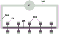
Fig. 1A-1F schematically illustrate an exemplary method for filling a microfluidic device. Fig. 1A schematically illustrates loading of a sample and immiscible fluid into a microfluidic device. The microfluidic device comprises an inlet 101, a channel 102 and a microchamber 103. The channels and microchambers of the microfluidic device are filled with air 104. The sample 105 is directed or injected into the inlet 101. Fig. 1B schematically illustrates pressurizing the microfluidic device to load a sample 105 into the channel 102. In this example, the microfluidic device includes a single inlet connected to both ends of the channel in a loop configuration. When pressure is applied, the sample 105 is simultaneously directed through both ends of the channel. Fig. 1C schematically shows continued pressurization to degas the fluid flow path and continue loading the sample into the channel. As the sample 105 enters the microchamber 103, a portion of the channel 103 is filled with an immiscible fluid 106, such as an oil or gas, which immiscible fluid 106 can be added simultaneously or sequentially with the sample (e.g., sample followed by immiscible fluid). As the sample 105 and immiscible fluid 106 fill the channels and microchambers, air 104 is directed through the membrane or membranes and expelled from the device. Fig. 1D schematically shows digitizing a portion of the sample 105 entering the microchamber 103 and continuing to load the immiscible fluid 106 into the channel 102. As sample 105 enters microchamber 103, air 104 within microchamber 103 is displaced through the membrane or membranes. Fig. 1E schematically shows further digitization and displacement of air 103. As immiscible fluid 106 fills the channel from both ends, the sample is directed into microchamber 103 and the volume of sample 105 within the channel decreases; fig. 1F schematically shows a complete digitization of the sample 105, wherein the immiscible fluid 106 fills the entire channel 102 and the sample 105 is isolated in the microchamber 103. In another example, the device has multiple inlets, and the sample and immiscible fluid are applied simultaneously to each inlet to fill the channels and microchambers.
Fig. 2A-2E show exemplary images of sample digitization in a microfluidic device. Fig. 2A shows an exemplary microfluidic device with two inlets. The sample and immiscible fluid (oil in this example) are applied simultaneously to both inlets. Fig. 2B shows the pressurized loading of the sample and oil into the microfluidic device. Both inlets are pressurized simultaneously to direct the sample and oil evenly into the channels of the device. Fig. 2C and 2D show that the sample and oil gradually fill the channels and microchambers of the device. Fig. 2E shows the exemplary device after complete digitization or partitioning of the sample within the device.
Fig. 3 schematically illustrates an exemplary method for digitization of a sample. The sample and immiscible fluid may be provided 301 at the inlet(s) of the microfluidic device. The inlet(s) may be pressurized 302 to load the sample and immiscible fluid into the channel. The inlet may be further pressurized to load the sample into the microchamber and fill the channel with an immiscible fluid to provide complete digitization of the sample 304.
By the presence of an indicator within the reagentTo verify the compartmentalization of the sample. The indicator may comprise a molecule comprising a detectable moiety. The detectable moiety may comprise a radioactive substance, a fluorescent label, a chemiluminescent label, an enzymatic label, a colorimetric label, or any combination thereof. Non-limiting examples of radioactive materials include3H、14C、22Na、32P、33P、35S、42K、45Ca、59Fe、123I、124I、125I、131I or203Hg. Non-limiting examples of fluorescent labels include fluorescent proteins, optically active dyes (e.g., fluorescent dyes), organometallic fluorophores, or any combination thereof. Non-limiting examples of chemiluminescent labels include enzymes of the luciferase class, such as firefly (Cypridina) luciferase, Gaussia (Gaussia) luciferase, Renilla (Renilla) luciferase and firefly luciferase. Non-limiting examples of enzyme labels include horseradish peroxidase (HRP), Alkaline Phosphatase (AP), beta-galactosidase, glucose oxidase, or other types of labels.
The indicator molecule may be a fluorescent molecule. Fluorescent molecules may include fluorescent proteins, fluorescent dyes, and organometallic fluorophores. In some embodiments, the indicator molecule is a protein fluorophore. The protein fluorophore may include a green fluorescent protein (GFP, a fluorescent protein that fluoresces in the green spectral region, typically emitting light at wavelength of 500-550 nm), a cyan fluorescent protein (CFP, a fluorescent protein that fluoresces in the cyan spectral region, typically emitting light at wavelength of 450-500 nm), a red fluorescent protein (RFP, a fluorescent protein that fluoresces in the red spectral region, typically emitting light at wavelength of 600-650 nm). Non-limiting examples of protein fluorophores include spectra of AcGFP, AcGFP1, AmCyan1, AQ143, AsRed2, Azami Green, Azurite, BFP, Cerulean, CFP, CGFP, Citrine, copeGFP, CyPet, dKeima-Tandem, DsRed, dsRed-Express, DsRed-Monomer, DsRed2, dTomato-Tandem, EBFP2, ECFP, EGFP, Emerald, EosFP, EYFP, HcRed-Tandem, HcRed1, JRed, Katuska, Kusabera Orange2, apple, mBanana, merean, mCErmComComCol, Satur, Saturrie, Saturgore, Samrkum Orange, Zkumage Orange2, SamrAW, Vemgerase, Vemgear, Vemgerase, Vemgear, Ve.
The indicator molecule may be a fluorescent dye. Non-limiting examples of fluorescent dyes include SYBR green; SYBR blue; DAPI; propidium iodide; hoeste; SYBR gold; ethidium bromide; acridine; proflavine; acridine orange; acriflavine; fluorescent coumarin (fluorocoumarins); ellipticine; daunomycin; chloroquine; distamycin D; chromomycin; ethidium (homidium); mithramycin; polypyridyl ruthenium; anthranilic acid; phenanthridine and acridine; ethidium bromide; propidium iodide; iodized hexane ingot; ethidium dihydrogen phosphate; ethidium homodimer-1 and ethidium homodimer-2; single stack nitriding of ethidium ingot; ACMA; hoechst 33258; hoechst 33342; hoechst 34580; DAPI; acridine orange; 7-AAD; actinomycin D; LDS 751; hydroxystilbamidine (hydroxystilbamidine); SYTOX blue; SYTOX green; SYTOX orange; POPO-1; POPO-3; YOYO-1; YOYO-3; TOTO-1; TOTO-3; JOJO-1; LOLO-1; BOBO-1; BOBO-3; PO-PRO-1; PO-PRO-3; BO-PRO-1; BO-PRO-3; TO-PRO-1; TO-PRO-3; TO-PRO-5; JO-PRO-1; LO-PRO-1; YO-PRO-1; YO-PRO-3; PicoGreen; OliGreen; RiboGreen; SYBR gold; SYBR green I; SYBR Green II; SYBR DX; SYTO-40, SYTO-41, SYTO-42, SYTO-43, SYTO-44 and SYTO-45 (blue); SYTO-13, SYTO-16, SYTO-24, SYTO-21, SYTO-23, SYTO-12, SYTO-11, SYTO-20, SYTO-22, SYTO-15, SYTO-14, and SYTO-25 (Green); SYTO-81, SYTO-80, SYTO-82, SYTO-83, SYTO-84 and SYTO-85 (orange); SYTO-64, SYTO-17, SYTO-59, SYTO-61, SYTO-62, SYTO-60 and SYTO-63 (Red); fluorescein; fluorescein Isothiocyanate (FITC); tetramethylrhodamine isothiocyanate (TRITC); (ii) a rhodamine; tetramethyl rhodamine; r-phycoerythrin; cy-2; cy-3; cy-3.5; cy-5; cy5.5; cy-7; texas Red (Texas Red); Phar-Red; allophycocyanin (APC); sybr green I; sybr green II; sybr gold; CellTracker Green; 7-AAD; ethidium homodimer I; ethidium homodimer II; ethidium homodimer III; ethidium bromide; umbelliferone; eosin; green fluorescent protein; erythrosine; coumarin; methylcoumarin; pyrene; malachite green; stilbene; yellow fluorescence; cascade blue (cascade blue); dichlorotriazinylamine fluorescein; dansyl chloride; fluorescent lanthanide complexes (such as those containing europium and terbium); carboxyl tetrachlorofluorescein; 5-carboxyfluorescein and/or 6-carboxyfluorescein (FAM); 5-iodoacetamido fluorescein or 6-iodoacetamido fluorescein; 5- { [2-5- (acetylmercapto) -succinyl ] amino } fluorescein and 5- { [3-5- (acetylmercapto) -succinyl ] amino } fluorescein (SAMSA-fluorescein); lissamine rhodamine B sulfonyl chloride; 5-carboxyrhodamine and/or 6-carboxyrhodamine (ROX); 7-amino-methyl-coumarin; 7-amino-4-methylcoumarin-3-acetic acid (AMCA); BODIPY fluorophore; 8-methoxypyrene-1, 3, 6-trisulfonic acid trisodium salt; 3, 6-disulfonate-4-amino-naphthalimide; phycobiliprotein; AlexaFluor 350, AlexaFluor 405, AlexaFluor 430, AlexaFluor 488, AlexaFluor 532, AlexaFluor 546, AlexaFluor 555, AlexaFluor 568, AlexaFluor 594, AlexaFluor 610, AlexaFluor 633, AlexaFluor 635, AlexaFluor 647, AlexaFluor 660, AlexaFluor 680, AlexaFluor 700, AlexaFluor 750, and AlexaFluor 790 dyes; DyLight 350, DyLight 405, DyLight 488, DyLight 550, DyLight 594, DyLight 633, DyLight 650, DyLight 680, DyLight 755, and DyLight 800 dyes; and other fluorophores.
The indicator molecule may be an organometallic fluorophore. Non-limiting examples of organometallic fluorophores include lanthanide ion chelates, non-limiting examples of which include tris (dibenzoylmethane) mono (1, 10-phenanthroline) europium (III), tris (dibenzoylmethane) mono (5-amino-1, 10-phenanthroline) europium (III), and Lumi4-Tb cryptate.
Fig. 4 schematically illustrates an exemplary method of using a microfluidic device for digital polymerase chain reaction (dPCR). The sample and reagent may be partitioned 401 as shown in fig. 2A-2E. The sample and reagents may be subjected to thermal cycling 402 to perform a PCR reaction on the reagents in the microchamber. Thermal cycling may be performed, for example, using a flat block thermal cycler. Image acquisition 403 may be performed to determine which microchambers have successfully performed a PCR reaction. Image acquisition may be performed, for example, using a three-color probe detection unit. Poisson statistics 404 may be applied to the count of microchambers determined in 403 to convert the raw number of positive microchambers to nucleic acid concentration.
The method may further comprise detecting one or more components of the solution, one or more components of the biological sample, or a reaction with one or more components of the biological sample. Detecting one or more components of the solution, one or more components of the biological sample, or the reaction may include imaging a microchamber. Images can be taken of the microfluidic device. Images may be taken of a single microchamber, an array of microchambers, or multiple arrays (simultaneously) simultaneously. Images may be taken through the body of the microfluidic device. Images may be taken through the membrane or films of the microfluidic device. In an example, images are taken through both the body and through the membrane of the microfluidic device. The body of the microfluidic device may be substantially optically transparent. Alternatively, the body of the microfluidic device may be substantially optically opaque. In an example, the film or membrane may be substantially optically transparent. Before the microfluidic device is filled with a sample, an image may be taken. After the microfluidic device is filled with sample, an image may be taken. During filling of the microfluidic device with a sample, images may be taken. Images may be taken to verify the sample's partitions. Images may be taken during the reaction to monitor the products of the reaction. In an example, the product of the reaction includes an amplification product. The images may be taken at specified intervals. Alternatively or additionally, the microfluidic device may be videotaped. The specified intervals can include taking images at least about every 300 seconds, 240 seconds, 180 seconds, 120 seconds, 90 seconds, 60 seconds, 30 seconds, 15 seconds, 10 seconds, 5 seconds, 4 seconds, 3 seconds, 2 seconds, 1 second, or more frequently during the reaction.
The biological sample may be any biological analyte, such as, but not limited to, a nucleic acid molecule, a protein, an enzyme, an antibody, or other biological molecule. In an example, the biological sample includes one or more nucleic acid molecules. Processing the nucleic acid molecules can also include thermocycling one or more microchambers to amplify the nucleic acid molecules. The method may further comprise controlling the temperature of the channel or microchamber(s). The method of using the microfluidic device may further comprise amplifying the nucleic acid sample. The microfluidic device may be filled with amplification reagents comprising nucleic acid molecules, components for the amplification reaction, indicator molecules and amplification probes. Amplification may be performed by thermocycling the plurality of microchambers. Detection of nucleic acid amplification can be performed by imaging a microchamber of the microfluidic device. Nucleic acid molecules can be quantified by counting the number of microchambers in which they were successfully amplified and applying poisson statistics. In some embodiments, nucleic acid amplification and quantification may be performed in a single integrated unit.
A variety of nucleic acid amplification reactions can be used to amplify nucleic acid molecules in a sample, thereby generating amplification products. Amplification of a nucleic acid target can be linear, exponential, or a combination thereof. Non-limiting examples of nucleic acid amplification methods include primer extension, polymerase chain reaction, reverse transcription, isothermal amplification, ligase chain reaction, helicase-dependent amplification, asymmetric amplification, rolling circle amplification, and multiple displacement amplification. In some embodiments, the amplification product is DNA or RNA. For embodiments involving DNA amplification, any DNA amplification method may be employed. Methods of DNA amplification include, but are not limited to, PCR, real-time PCR, assembly PCR, asymmetric PCR, digital PCR, dial-out PCR, helicase-dependent PCR, nested PCR, hot start PCR, inverse PCR, methylation specific PCR, miniprimer (minimer) PCR, multiplex PCR, overlap-extension PCR, thermal asymmetric staggered PCR, touchdown PCR, and ligase chain reaction. In some embodiments, the DNA amplification is linear, exponential, or a combination thereof. In some embodiments, DNA amplification is performed using digital pcr (dpcr).
Reagents used for nucleic acid amplification may include polymerases, reverse primers, forward primers, and amplification probes. Examples of polymerases include, but are not limited to, nucleic acid polymerases, transcriptases, or ligases (i.e., enzymes that catalyze bond formation). The polymerase may be naturally occurring or synthetic. Examples of polymerases include DNA polymerase, RNA polymerase, thermostable polymerase, wild-type polymerase, modified polymerase, E.coli (E.coli) DNA polymerase I, T7 DNA polymerase, bacteriophage T4 DNA polymerase, Φ 29(phi29) DNA polymerase, Taq polymerase, Tth polymerase, Tli polymerase, Pfu polymerase, Pwo polymerase, VENT polymerase, DEEPVENT polymerase, Ex-Taq polymerase, LA-Taw polymerase, Sso polymerase, Poc polymerase, Pab polymerase, Mth polymerase, ES4 polymerase, Tru polymerase, Tac polymerase, Tne polymerase, Tma polymerase, Tca polymerase, Tih polymerase, Tfi polymerase, Platinum Taq polymerase, Tbr polymerase, Tfl polymerase, Pfunbo polymerase, Pyrobe polymerase, KOD polymerase, Bst polymerase, Sac polymerase, Klenow fragment polymerase having 3 'to 5' exonuclease activity, and variants thereof, Modified products and derivatives. For hot start polymerases, a denaturation step at a temperature of about 92 ℃ to 95 ℃ for about 2 to 10 minutes may be required.
The amplification probes may be sequence-specific oligonucleotide probes. The amplification probes may be optically active when hybridized to the amplification products. In some embodiments, the amplification probe is only detectable when nucleic acid amplification is performed. The intensity of the optical signal may be proportional to the amount of amplified product. The probe can be linked to any optically active detectable moiety (e.g., dye) described herein, and can further include a quencher capable of blocking the optical activity of the associated dye. Non-limiting examples of probes that can be used as detectable moieties include TaqMan probes, TaqMan Tamara probes, TaqMan MGB probes, Lion probes, locked nucleic acid probes, or molecular beacons. Non-limiting examples of quenchers that can be used to block the optical activity of the probe include Black Hole Quenchers (BHQ), Iowa Black FQ and RQ quenchers, or Internal ZEN quenchers. Alternatively or additionally, a probe or quencher can be any probe that can be used in the context of the methods of the present disclosure.
The amplification probe is a dual-labeled fluorescent probe. The dual labeled probe may comprise a fluorescent reporter and a fluorescent quencher linked to a nucleic acid. The fluorescent reporter and the fluorescence quencher can be positioned in close proximity to each other. The optical activity of the fluorescent reporter can be blocked by the fluorescent reporter and the fluorescence quencher in close proximity. The dual labeled probe can bind to a nucleic acid molecule to be amplified. During amplification, the fluorescent reporter and the fluorescent quencher can be cleaved by the exonuclease activity of the polymerase. Cleavage of the fluorescent reporter and quencher from the amplification probe allows the fluorescent reporter to regain its optical activity and be detected. The dual-labeled fluorescent probe can include a 5' fluorescent reporter having an excitation wavelength maximum of at least about 450 nanometers (nm), 500nm, 525nm, 550nm, 575nm, 600nm, 625nm, 650nm, 675nm, 700nm, or more, and an emission wavelength maximum of about 500nm, 525nm, 550nm, 575nm, 600nm, 625nm, 650nm, 675nm, 700nm, or more. The dual-labeled fluorescent probe may also comprise a 3' fluorescence quencher. The fluorescence quencher may quench a fluorescence emission wavelength between about 380nm and 550nm, 390nm and 625nm, 470nm and 560nm, 480nm and 580nm, 550nm and 650nm, 550nm and 750nm, or 620nm and 730 nm.
Nucleic acid amplification can be performed by thermal cycling of a microchamber of a microfluidic device. Thermal cycling may include controlling the temperature of the microfluidic device by applying heat or cooling to the microfluidic device. The heating or cooling method may include resistive heating or cooling, radiative heating or cooling, conductive heating or cooling, convective heating or cooling, or any combination thereof. The thermal cycle may include the following cycles: the microchamber is incubated at a temperature sufficiently high to denature the nucleic acid molecules for a duration of time, followed by incubating the microchamber at an extension temperature for an extension duration of time. The denaturation temperature may vary depending on, for example, the particular nucleic acid sample, the reagents used, and the reaction conditions. The denaturation temperature can be from about 80 ℃ to 110 ℃, 85 ℃ to about 105 ℃, 90 ℃ to about 100 ℃, 90 ℃ to about 98 ℃, 92 ℃ to about 95 ℃. The denaturation temperature can be at least about 80 ℃, 81 ℃, 82 ℃, 83 ℃, 84 ℃, 85 ℃, 86 ℃, 87 ℃, 88 ℃, 89 ℃, 90 ℃, 91 ℃, 92 ℃, 93 ℃, 94 ℃, 95 ℃, 96 ℃, 97 ℃, 98 ℃, 99 ℃, 100 ℃ or higher.
The duration of denaturation can vary depending on, for example, the particular nucleic acid sample, the reagents used, and the reaction conditions. The duration of denaturation can be less than or equal to about 300 seconds, 240 seconds, 180 seconds, 120 seconds, 90 seconds, 60 seconds, 55 seconds, 50 seconds, 45 seconds, 40 seconds, 35 seconds, 30 seconds, 25 seconds, 20 seconds, 15 seconds, 10 seconds, 5 seconds, 2 seconds, or 1 second.
The extension temperature may vary depending on, for example, the particular nucleic acid sample, the reagents used, and the reaction conditions. The extension temperature may be about 30 ℃ to 80 ℃, 35 ℃ to 75 ℃, 45 ℃ to 65 ℃, 55 ℃ to 65 ℃, or 40 ℃ to 60 ℃. The extension temperature can be at least about 35 ℃, 36 ℃, 37 ℃, 38 ℃, 39 ℃, 40 ℃, 41 ℃, 42 ℃, 43 ℃, 44 ℃, 45 ℃, 46 ℃, 47 ℃, 48 ℃, 49 ℃,50 ℃, 51 ℃, 52 ℃, 53 ℃, 54 ℃, 55 ℃, 56 ℃, 57 ℃, 58 ℃, 59 ℃, 60 ℃,61 ℃, 62 ℃, 63 ℃, 64 ℃, 66 ℃, 67 ℃, 68 ℃, 69 ℃, 70 ℃, 71 ℃, 72 ℃, 73 ℃, 74 ℃, 75 ℃, 76 ℃, 77 ℃, 78 ℃, 79 ℃ or 80 ℃.
The extension time can vary depending on, for example, the particular nucleic acid sample, the reagents used, and the reaction conditions. In some embodiments, the extension duration may be less than or equal to about 300 seconds, 240 seconds, 180 seconds, 120 seconds, 90 seconds, 60 seconds, 55 seconds, 50 seconds, 45 seconds, 40 seconds, 35 seconds, 30 seconds, 25 seconds, 20 seconds, 15 seconds, 10 seconds, 5 seconds, 2 seconds, or 1 second. In alternative embodiments, the extension duration may be no more than about 120 seconds, 90 seconds, 60 seconds, 55 seconds, 50 seconds, 45 seconds, 40 seconds, 35 seconds, 30 seconds, 25 seconds, 20 seconds, 15 seconds, 10 seconds, 5 seconds, 2 seconds, or 1 second. In an example, the duration of the extension reaction is less than or equal to about 10 seconds.
Nucleic acid amplification may include multiple cycles of thermal cycling. Any suitable number of cycles may be performed. The number of cycles performed may be greater than about 5, 10, 15, 20, 30, 40, 50, 60, 70, 80, 90, 100 cycles, or more. The number of cycles performed may depend on the number of cycles required to obtain a detectable amplification product. For example, the number of cycles required to detect nucleic acid amplification during dPCR may be less than or equal to about 100, 90, 80, 70, 60, 50, 40, 30, 20, 15, 10, 5 cycles or less. In an example, less than or equal to about 40 cycles are employed, and the cycle time is less than or equal to about 20 minutes.
The time required to achieve a detectable amount of amplification product may vary depending on the particular nucleic acid sample, the reagents used, the amplification reaction used, the number of amplification cycles used, and the reaction conditions. In some embodiments, the time required to reach a detectable amount of amplification product may be about 120 minutes or less, 90 minutes or less, 60 minutes or less, 50 minutes or less, 40 minutes or less, 30 minutes or less, 20 minutes or less, 10 minutes or less, or 5 minutes or less. In an example, a detectable amount of amplification product can be reached in less than 20 minutes.
In some embodiments, the ramp rate (i.e., the rate at which the microchamber transitions from one temperature to another) is important for amplification. For example, the temperature and time required for an amplification reaction to produce a detectable amount of amplification product may vary depending on the ramp rate. The ramp rate may affect the time, temperature, or both time and temperature used during amplification. The ramp rate may affect the time, temperature, or both time and temperature used during amplification. In some embodiments, the ramp rate is constant between cycles. In some embodiments, the ramp rate varies between cycles. The ramp rate may be adjusted based on the sample being processed. For example, an optimal ramp rate may be selected to provide a robust and efficient amplification method.
System for analyzing a sample
In another aspect, the present disclosure may provide a system for processing a biological sample. The system can include a device (e.g., a microfluidic device), a holder, and a fluid flow channel. The device may include a fluid flow path and a microchamber. The fluid flow path may include a channel and an inlet. The fluid flow path may not include an outlet. The inlet may be configured to direct a solution comprising a biological sample into the channel. The microchamber may be in fluid communication with the channel. The microchamber may be configured to receive at least a portion of a solution comprising the biological sample from the channel and retain the solution during processing. The holder may be configured to receive and hold the device during processing. The fluid flow module may be configured to fluidly couple to the inlet and provide a pressure differential to flow the solution from the inlet to the channel. Further, the fluid flow module may be configured to provide a pressure differential to cause at least a portion of the solution to flow from the channel to the microchamber.
The holder may be a shelf, receptacle or stage for receiving the device. In an example, the holder is a transfer table. The transfer station may be configured to input, hold, and output microfluidic devices. The microfluidic device may be any of the devices described elsewhere herein. The transfer station may be fixed at one or more coordinates. Alternatively or additionally, the transfer table may be movable in the X-direction, Y-direction, Z-direction, or any combination thereof. The transfer station may be capable of holding a single microfluidic device. Alternatively or additionally, the transfer station may be capable of holding at least 2, 3, 4, 5, 6, 7, 8, 9, 10 or more microfluidic devices.
The fluid flow module may be a pneumatic module and/or a vacuum module. The fluid flow module may be configured to be in fluid communication with the inlet(s) of the microfluidic device. The fluid flow module may have a plurality of connection points connectable to a plurality of inlets. The fluid flow module may be capable of filling, backfilling and zoning a single array of microchambers or a plurality of arrays of microchambers in series at a time. The fluid flow module may be a pneumatic module in combination with a vacuum module. The fluid flow module may provide an increased pressure to the microfluidic device or a vacuum to the microfluidic device.
The system may further comprise a thermal module. The thermal module can be configured to be in thermal communication with a microchamber of the microfluidic device. The thermal module may be configured to control the temperature of a single array of microchambers or to control the temperature of multiple arrays of microchambers. Each micro-chamber array may be individually addressable by the thermal module. For example, the thermal module may perform the same thermal procedure in all arrays of microchambers, or may perform different thermal procedures in different arrays of microchambers. The thermal module can be in thermal communication with the microfluidic device and/or a microchamber of the microfluidic device. The thermal module may heat or cool the microfluidic device. One or more surfaces of the microfluidic device may be in direct contact with the thermic module. Alternatively or additionally, a thermally conductive material may be disposed between the thermal module and the microfluidic device. The thermal module can maintain a temperature across the surface of the microfluidic device such that the variation is less than or equal to about 2 ℃, 1.5 ℃,1 ℃, 0.9 ℃, 0.8 ℃, 0.7 ℃, 0.6 ℃, 0.5 ℃, 0.4 ℃, 0.3 ℃, 0.2 ℃, 0.1 ℃ or less. The thermal module can maintain the temperature of the surface of the microfluidic device within plus or minus about 0.5 ℃, 0.4 ℃, 0.3 ℃, 0.2 ℃, 0.1 ℃, 0.05 ℃ or closer to the temperature set point.
The system may further comprise a detection module. The detection module may provide electrical or optical detection. In an example, the detection module is an optical module that provides optical detection. The optical module may be configured to emit and detect light at multiple wavelengths. The emission wavelength may correspond to the excitation wavelength of the indicator and amplification probes used. The emitted light may comprise a wavelength having a maximum intensity near about 450nm, 500nm, 525nm, 550nm, 575nm, 600nm, 625nm, 650nm, 675nm, 700nm, or any combination thereof. The detected light may comprise a wavelength having a maximum intensity near about 500nm, 525nm, 550nm, 575nm, 600nm, 625nm, 650nm, 675nm, 700nm, or any combination thereof. The optical module may be configured to emit more than one, two, three, four, or more wavelengths of light. The optical module may be configured to detect more than one, two, three, four or more wavelengths of light. One emitted light wavelength may correspond to the excitation wavelength of one indicator molecule. The other emission wavelength may correspond to an excitation wavelength of one of the amplification probes. One detected light wavelength may correspond to the emission wavelength of one indicator molecule. Another wavelength of detection light may correspond to one of the amplification probes used to detect the reaction within the micro chamber. The optical module may be configured to image a cross-section of the array of microchambers. Alternatively or additionally, the optical module may image the entire array of microchambers in a single image. In an example, an optical module is configured to take a video recording of the apparatus.
Fig. 5 illustrates a system 500 for performing the process of fig. 4 in a single system. The system 500 includes a fluid flow module 501, which may include a pump, vacuum, and manifold, and may be movable in the Z-direction, operable to perform application of pressure, as described in fig. 1A-1F. System 500 may also include a thermal module 502, such as a flat block thermal cycler, to thermally cycle the microfluidic device and thereby allow polymerase chain reaction to occur. The system 500 also includes an optical module 503, such as an epifluorescence optical module, that can optically determine which microchambers in the microfluidic device have successfully performed a PCR reaction. Optical module 503 can provide this information to processor 504, which can convert the raw counts of successful microchambers into nucleic acid concentrations using poisson statistics. The holder 505 may be used to move a given microfluidic device between various modules and to operate multiple microfluidic devices simultaneously. The microfluidic devices described above, in combination with including this functionality in a single machine, can reduce cost, workflow complexity, and space required for dPCR compared to other embodiments of dPCR.
The system may also include a robotic arm. The robotic arm can move, change, or arrange the position of the microfluidic device. Alternatively or additionally, the robotic arm may arrange or move other components of the system (e.g., a fluid flow module or a detection module). The detection module may include a camera (e.g., a Complementary Metal Oxide Semiconductor (CMOS) camera) and a filter block. The filter block may change or adjust the wavelength of the excitation light and/or the wavelength of the light detected by the camera. The fluid flow module may include a manifold (e.g., a pneumatic manifold) and/or one or more pumps. The manifold may be in an upright position such that the manifold does not contact the microfluidic device. The upright position may be employed when loading and/or imaging the microfluidic device. The manifold may be in a downward position such that the manifold contacts the microfluidic device. The manifold may be used to load fluids (e.g., samples and reagents) into the microfluidic device. The manifold may apply pressure to the microfluidic device to hold the device in place and/or to avoid warping, bending, or other stresses during use. In an example, the manifold applies downward pressure and holds the microfluidic device against the thermal module.
The system may also include one or more computer processors. The one or more computer processors may be operably coupled to the fluid flow module, the holder, the thermal module, the detection module, the robotic arm, or any combination thereof. In an example, one or more computer processors are operatively coupled to the fluid flow module. The one or more computer processors may be individually or collectively programmed to command the fluid flow module to provide a pressure differential to the inlet to cause the solution to flow from the inlet to the channel and/or from the channel to the microchamber(s) when the fluid flow module is fluidly coupled to the inlet and thereby partition by pressurizing and degassing the microchamber.
The present disclosure is not to be limited in scope by the specific embodiments described herein. Indeed, other various embodiments and modifications of the disclosure in addition to those described herein will be apparent to those of ordinary skill in the art from the foregoing description and accompanying drawings.
For example, although described in the context of dPCR applications, other microfluidic devices that may require a number of separate microchambers filled with liquid separated via gas or other fluids may benefit from the use of thermoplastic films to allow degassing to avoid gas contamination while also providing advantages with respect to manufacturability and cost. In accordance with embodiments of the present disclosure, in addition to PCR, other nucleic acid amplification methods, such as loop-mediated isothermal amplification, may be suitable for performing digital detection of a particular nucleic acid sequence. Microchambers can also be used to separate individual cells, wherein the siphon-hole is designed to approximate the diameter of the cell to be separated. In some embodiments, embodiments of the present disclosure may be used to separate plasma from whole blood when the siphon holes are much smaller than the size of blood cells.
The system may be used with any of the devices (e.g., microfluidic devices) described elsewhere herein. Further, the system may be used to implement any of the methods described elsewhere herein.
Computer system
The present disclosure provides a computer system programmed to implement the methods of the present disclosure. Fig. 6 shows a computer system 601 programmed or otherwise configured to process and analyze biological samples (e.g., nucleic acid molecules). The computer system 601 can regulate various aspects of the systems and methods of the present disclosure, for example, loading, digitizing, and analyzing biological samples. Computer system 601 may be a user's electronic device or a computer system remotely located from the electronic device. The electronic device may be a mobile electronic device that is capable of or otherwise configured to monitor and control the bio-analysis system.
The storage unit 615 may store files such as drivers, libraries, and saved programs. The storage unit 615 may store user data, such as user preferences and user programs. In some cases, computer system 601 may include one or more additional data storage units located external to computer system 601, such as on a remote server in communication with computer system 601 over an intranet or the Internet.


The methods as described herein may be implemented by way of machine (e.g., computer processor) executable code that is stored on an electronic storage location of computer system 601, such as memory 610 or electronic storage unit 615. The machine executable code or machine readable code may be provided in the form of software. In use, the code may be executed by processor 605. In some cases, the code may be retrieved from storage unit 615 and stored on memory 610 for access by processor 605. In some cases, electronic storage unit 615 may be eliminated, and machine-executable instructions stored on memory 610.
The code may be pre-compiled and configured for use with a machine having a processor adapted to execute the code, or may be compiled during runtime. The code may be provided in a programming language which may be selected to enable the code to be executed in a pre-compiled or just-in-time compiled manner.
Aspects of the systems and methods provided herein, such as the computer system 601, may be embodied in programming. Various aspects of the technology may be considered an "article of manufacture" or "article of manufacture" typically in the form of machine (or processor) executable code and/or associated data carried on or embodied in a type of machine-readable medium. The machine executable code may be stored on an electronic storage unit such as a memory (e.g., read only memory, random access memory, flash memory) or a hard disk. A "storage" type medium may include any or all of a tangible memory of a computer, processor, etc., or associated units or modules thereof, such as various semiconductor memories, tape drives, disk drives, etc., that may provide non-transitory storage for software programming at any time. All or a portion of the software may sometimes be in communication via the internet or various other telecommunications networks. For example, such communication may enable software to be loaded from one computer or processor into another computer or processor, e.g., from a management server or host into the computer platform of an application server. Thus, another type of media that can carry software elements includes optical, electrical, and electromagnetic waves, such as those used across physical interfaces between local devices, through wired and optical land-line networks, and through various air links. The physical elements that carry such waves, such as wired or wireless links, optical links, etc., may also be considered as media carrying software. As used herein, unless limited to a non-transitory tangible "storage" medium, terms such as a computer or machine "readable medium" refer to any medium that participates in providing instructions to a processor for execution.
Thus, a machine-readable medium, such as computer executable code, may take many forms, including but not limited to tangible storage media, carrier wave media, or physical transmission media. Non-volatile storage media include, for example, optical or magnetic disks, such as any storage device in any computer, etc., such as may be used to implement a database as shown in the figures. Volatile storage media includes dynamic memory, such as the main memory of such a computer platform. Tangible transmission media include coaxial cables; copper wire and fiber optics, including the wires that comprise a bus within a computer system. Carrier-wave transmission media can take the form of electrical or electromagnetic signals, or acoustic or light waves, such as those generated during Radio Frequency (RF) and Infrared (IR) data communications. Thus, common forms of computer-readable media include, for example: a floppy disk, a flexible disk, hard disk, magnetic tape, any other magnetic medium, a CD-ROM, DVD or DVD-ROM, any other optical medium, punch cards, paper tape, any other physical storage medium with patterns of holes, a RAM, a ROM, a PROM, and EPROM, a FLASH-EPROM, any other memory chip or cartridge, a carrier wave transporting data or instructions, cables or links transporting such a carrier wave, or any other medium from which a computer can read programming code and/or data. Many of these forms of computer readable media may be involved in carrying one or more sequences of one or more instructions to a processor for execution.
The computer system 601 may include or be in communication with an electronic display 635 that includes a User Interface (UI)640 to provide, for example, processing parameters, data analysis, and results of a biometric or reaction (e.g., PCR). Examples of UIs include, without limitation, Graphical User Interfaces (GUIs) and web-based user interfaces.
The methods and systems of the present disclosure may be implemented by way of one or more algorithms. The algorithm may be implemented by software executed by the central processing unit 605. Algorithms can, for example, regulate or control the system or implement the methods provided herein (e.g., sample loading, thermocycling, detection, etc.).
Examples
Example 1: microfluidic device comprising a plurality of processing units
Fig. 7A and 7B show examples of microfluidic devices for processing biological samples. The microfluidic device 701 includes a plurality of slides, e.g., 4 slides, as shown in fig. 7B. The microfluidic device 701 can include at least 1, 2, 3, 4, 5, 6, 7, 8, 9, 10, or more slides. The plurality of slides may be bonded to the automated compatible plate frame by welding. The plate frame may be a standard format plate frame with a single inlet aperture as shown in fig. 7B. Other suitable methods may also be used to bond the plurality of slides together. A single slide 702 (a four-unit array having about 20,000 sections/unit) includes a plurality of processing units, e.g., 4 processing units, as shown in fig. 7A. In addition, the slide 702 can include 1, 2, 3, 4, 5, 6, 7, 8, 9, 10, or more processing units.
In addition, a single processing unit includes about 20,000 microchambers/zones, and a single zone/microchamber 704 is shown in fig. 7A. In addition, each processing unit includes a channel, as shown in FIGS. 1A-1F. Each processing unit, as described herein, includes a single inlet. The individual microchambers/partitions 704 have a length of about 85 μm, a width of about 65 μm, and a height of about 100 μm. In addition, a single microchamber/partition 704 may include microchannels 705 having a depth of about 10 μm and a width of about 15 μm. Due to the size of each processing unit, for example, processing unit 703, a total analysis volume of about 11.5 μ L may be included. Furthermore, each processing unit contains less than 10% dead volume.
Example 2: loading biological samples and reagents into microfluidic devices
Fig. 8 shows a microscope image of a single processing unit 801. Fig. 8 also includes a 650 μm scale indicated by solid lines located at the corners of the microscope image. As shown in the various configurations 802, 803, and 804 of the primary channel, the primary channel 805 is configured to lead to a plurality of microchannels that are configured to connect to and be in fluid communication with one or more partitions/microchambers.
For example, to load a processing unit, a combined liquid of biological sample and reagent is first flowed into the processing unit followed by an immiscible fluid, such as an inert silicone oil. Immiscible fluids are configured to clear the main channel of this combined liquid and isolate individual partitions/microchambers for PCR reactions, e.g., thermal cycling, and subsequent detection analysis.
Additionally, to address the problem of overloading with fluid, each processing unit may include one or more sacrificial microchambers 806, the sacrificial microchambers 806 configured to connect to and be in fluid communication with the primary channel 805. Each primary channel can be connected to and in fluid communication with 1, 2, 3, 4, 5, 6, 7, 8, 9, 10, or more sacrificial microchambers. The sacrificial microchambers may have different shapes and may contain different volumes. When the processing unit is overloaded with fluid and some residual liquid remains in the main channel (especially towards the end of the fluid flow), one or more adjacent partitions/microchambers become in fluid communication with the overloaded processing unit. In addition, one or more target molecules contained in the overloaded fluid may infiltrate into adjacent partitions/microchambers during the PCR amplification process. One or more sacrificial microchambers 806 located in each processing unit are configured to capture excess fluid and enable immiscible fluid to completely clear the main channel. Thus, the sacrificial microchamber helps to account for slight variations in the volume of the combined fluids (e.g., biological sample and reagents) loaded (e.g., which may be due to pipetting errors). The sacrificial microchamber 806 may also help isolate the PCR reaction in each partition/microchamber so that the signal generated by the PCR reaction can be accurately quantified.
Example 3: digitization of a combined fluid of biological samples and reaction reagents
Fig. 9A-9D show the use of a single inlet and any outlet to load and digitize a combined fluid of biological sample and reagent. A pneumatic controller (not shown in fig. 9A-9D) was used and a PCR reagent mixture containing the common qPCR calibration dye ROX was used to visualize the digitization process.
The digitization process may be accomplished with a single pressure step or multiple pressure steps. For example, to load each processing unit of the microfluidic device 701 (fig. 7A), approximately 10 μ L of a reaction reagent (containing a target nucleic acid molecule from a biological sample) is loaded (e.g., by pipetting) into an inlet well 706 on the microfluidic device 701 (fig. 7A). Additionally, approximately 7 μ L of the buffer/silicone oil buffer is loaded (e.g., by pipetting) into the inlet port 706 on the microfluidic device 701. A pneumatic controller is then used to apply a positive pressure of about 50PSI to the inlet port 706 for about 60 minutes or until reagent digitization is complete. Approximately 50PSI may be ramped up gradually. The buffer/silicone oil is configured to act as a cover liquid and to be placed over the PCR reagents during the loading process, thereby ensuring that the PCR reagents first enter the microfluidic array because they are less dense than water. After the digitization process is complete, the partitions/microchambers are fluidically isolated, allowing them to independently perform PCR when activated.
In addition, fig. 9A-9D show 4 different points in time during the digitization process. Figure 9A shows a first point in time when reagent first enters the array. Figure 9B shows a second point in time when the reagent has passed almost the entire array, and the loading channels are now filled with reagent in the array while the microchambers are mostly still empty. Fig. 9C shows a third point in time when reagent has entered the microchamber, but while the microchamber is still fluidly connected, and fig. 9D shows that at a fourth point in time after the reagent is depleted, oil moves through the array, displacing all of the reagent in the main fluid channel. The first row of fig. 9A-9D shows fluorescence images of the entire array at 4 time points as the reagents begin to fill the array, fill most of the main and loading channels, enter the microchamber, and only progress in the replacement of the main channel with silicone oil. The middle row of fig. 9A-9D shows a schematic of the micro-chamber array at the 4 time points described above. The bottom row of fig. 9A-9D shows magnified images of the progression of the time points.
Example 4: integrating digitization processes into laboratory workflows
The digitization process can be easily integrated into a common laboratory workflow for nucleic acid assays, as shown in fig. 10. Biological sample preparation (sample preparation step) can be performed in other PCR-based workflows, including nucleic acid isolation and combining Master Mix and primers/probes with biological samples. The microfluidic device 701 is loaded (load plate step), as described herein (e.g., pipetting sample mixture followed by pipetting oil cover), and then placed in an instrument that integrates pneumatic loading/digitization, thermocycling, and data/image acquisition of reagents (reagent partitioning + PCR + image acquisition step and analysis step). The collected data of the PCR reaction can then be analyzed by downstream software to provide results, e.g., concentrations, of the target gene in the initial biological sample.
Example 5: image analysis
FIG. 11 shows a screenshot of a user interface of software that analyzes a captured image. Figure 11 shows the actual results of a dPCR assay performed with four different indicators (indicated by four different fluorescent colors) using human genomic DNA as the sample. The analysis settings displayed in the panel 1101 are selectable by the user. The results from a single one of the sixteen process units on the microfluidic device 701, in this case unit C3, are shown in the form of a scatter plot in the plot 1104, and the concentration values are shown in the plot 1103. The central image in panel 1102 is a composite image that superimposes positive results from each of the four optical channels used to detect the target gene. The fifth optical channel serves as a quality control channel.
While preferred embodiments of the present invention have been shown and described herein, it will be obvious to those skilled in the art that such embodiments are provided by way of example only. The specific examples provided in the specification are not intended to limit the present invention. While the invention has been described with reference to the foregoing specification, the descriptions and illustrations of the embodiments herein are not meant to be construed in a limiting sense. Numerous variations, changes, and substitutions will now occur to those skilled in the art without departing from the invention. Further, it is to be understood that all aspects of the present invention are not limited to the specific depictions, configurations or relative proportions set forth herein which depend upon a variety of conditions and variables. It should be understood that various alternatives to the embodiments of the invention described herein may be employed in practicing the invention. It is therefore contemplated that the present invention shall cover any such alternatives, modifications, variations or equivalents. It is intended that the following claims define the scope of the invention and that methods and structures within the scope of these claims and their equivalents be covered thereby.
Claims (53)
1. A microfluidic device for processing a biological sample, comprising:
a fluid flow path comprising a channel and an inlet, wherein the fluid flow path does not comprise an outlet, and wherein the inlet is configured to direct a solution comprising the biological sample to the channel; and
a microchamber in fluid communication with the channel, wherein the microchamber is configured to receive at least a portion of the solution from the channel and retain the at least a portion of the solution during the treatment.
2. The microfluidic device of claim 1, further comprising a plurality of microchambers in fluid communication with the channel, wherein the plurality of microchambers comprises the microchamber.
3. The microfluidic device of claim 1, wherein the channel comprises a first end and a second end, and wherein the first end and the second end are connected to a single inlet.
4. The microfluidic device of claim 3, wherein the fluid flow path is annular.
5. The microfluidic device of claim 1, wherein the channel comprises a first end and a second end, and wherein the first end is connected to the inlet and the second end is connected to a different inlet.
6. The microfluidic device of claim 1, wherein the microchamber is configured to allow pressurized venting.
7. The microfluidic device of claim 6, wherein the microchamber comprises a membrane or membrane that allows the pressurization to vent.
8. The microfluidic device of claim 7, wherein the film or membrane is a polymer film or membrane.
9. The microfluidic device of claim 8, wherein the polymer film or membrane does not comprise an elastomer.
10. The microfluidic device of claim 7, wherein the thin film or membrane has a thickness of less than about 100 micrometers (μ ι η).
11. The microfluidic device of claim 10, wherein the thickness is less than about 50 μ ι η.
12. The microfluidic device of claim 7, wherein the membrane or membrane is substantially liquid impermeable.
13. The microfluidic device of claim 1, wherein the fluid flow path or the microchamber does not comprise a valve.
14. The microfluidic device of claim 1, wherein the volume of the microchamber is less than or equal to about 500 picoliters.
15. The microfluidic device of claim 1, wherein the volume of the microchamber is less than or equal to about 250 picoliters.
16. The microfluidic device of claim 1, wherein the microchamber has a cross-sectional dimension of less than or equal to about 250 μ ι η.
17. The microfluidic device of claim 1, wherein the microchamber has a depth less than or equal to about 250 μ ι η.
18. The microfluidic device of claim 1, further comprising a siphon orifice disposed between the channel and the microchamber, wherein the siphon orifice is configured to provide fluid communication between the channel and the microchamber.
19. The microfluidic device of claim 1, further comprising a sacrificial microchamber in fluid communication with the channel.
20. The microfluidic device of claim 19, wherein the sacrificial microchamber is configured to retain an excess portion of a solution comprising the biological sample.
21. A method for processing a biological sample, comprising:
(a) providing a device comprising (i) a fluid flow path comprising a channel and an inlet, wherein the fluid flow path does not comprise an outlet, and (ii) a microchamber in fluid communication with the channel;
(b) directing a solution comprising the biological sample from the inlet to the channel; and
(c) directing at least a portion of the solution from the channel to the microchamber, the microchamber retaining the at least a portion of the solution during the treatment.
22. The method of claim 21, wherein the device comprises a plurality of microchambers in fluid communication with the channel, and wherein the plurality of microchambers comprises the microchamber.
23. The method of claim 21, further comprising applying a single pressure differential to the inlet to direct the solution from the inlet to the channel and from the channel to the microchamber.
24. The method of claim 23, wherein the single pressure differential allows for pressurized venting of gas in the microchamber.
25. The method of claim 21, further comprising applying a first pressure differential to the inlet to direct the solution from the inlet to the channel.
26. The method of claim 25, further comprising applying a second pressure differential to the inlet to direct the solution from the channel to the microchamber.
27. The method of claim 26, wherein the second pressure differential is greater than the first pressure differential.
28. The method of claim 26, wherein the second pressure differential allows for pressurized venting of gas in the microchamber.
29. The method of claim 24 or 28, wherein the microchamber comprises a membrane or membrane, and wherein the membrane or membrane allows for pressurized venting of the gas in the microchamber.
30. The method of claim 21, wherein the volume of the solution is less than or equal to the volume of the microchamber.
31. The method of claim 30, wherein the device partitions the solution comprising the biological sample into the microchamber such that no residual solution remains in the channel.
32. The method of claim 21, further comprising providing an immiscible fluid to the inlet and directing the immiscible fluid to the channel.
33. The method of claim 32, wherein the immiscible fluid has a volume greater than the volume of the channel.
34. The method of claim 21, wherein the biological sample is a nucleic acid molecule.
35. The method of claim 34, further comprising amplifying the nucleic acid molecule by thermal cycling the microchamber.
36. The method of claim 21, further comprising controlling the temperature of the channel or the microchamber.
37. The method of claim 21, further comprising detecting one or more components of the biological sample in the microchamber, or a reaction with the one or more components of the biological sample.
38. The method of claim 37, wherein detecting the one or more components of the biological sample or the reaction comprises imaging the microchamber.
39. A system for processing a biological sample, comprising:
a device comprising (i) a fluid flow path comprising a channel and an inlet, wherein the fluid flow path does not comprise an outlet, and wherein the inlet is configured to direct a solution comprising the biological sample to the channel; and (ii) a microchamber in fluid communication with the channel, wherein the microchamber is configured to receive at least a portion of the solution from the channel and retain the at least a portion of the solution during the treatment;
a holder configured to receive or hold the device during the process; and
a fluid flow module configured to be fluidly coupled to the inlet and to provide a pressure differential to cause (i) the solution to flow from the inlet to the channel and (ii) at least a portion of the solution to flow from the channel to the microchamber.
40. The system of claim 39, wherein the device comprises a plurality of microchambers in fluid communication with the channel, and wherein the plurality of microchambers comprises the microchamber.
41. The system of claim 39, wherein the microchamber of the device is configured to: allowing pressurized venting of gas in the microchamber when the fluid flow module applies the pressure differential to the inlet.
42. The system of claim 41, wherein the microchamber comprises a membrane or membrane configured to allow the pressurized venting.
43. The system of claim 39, further comprising one or more computer processors operatively coupled with the fluid flow module, wherein the one or more computer processors are individually or collectively programmed to: when the fluid flow module is fluidly coupled to the inlet, instructing the fluid flow module to provide the pressure differential to cause the solution to flow from the inlet to the channel and to direct the at least a portion of the solution from the channel to the microchamber.
44. The system of claim 39, further comprising a thermal module in thermal communication with the microchamber, wherein the thermal module is configured to control the temperature of the microchamber during the processing.
45. The system of claim 39, further comprising a detection module in communication with the microchamber, wherein the detection module is configured to detect contents of the microchamber during the processing.
46. The system of claim 45, wherein the detection module is an optical module in optical communication with the microchamber.
47. The system of claim 48, wherein the optical module is configured to image the microchamber.
48. A system for processing a biological sample, comprising:
a holder configured to hold a device comprising (i) a fluid flow path comprising a channel and an inlet, wherein the fluid flow path does not comprise an outlet, and (ii) a microchamber in fluid communication with the channel; and
one or more computer processors configured to operably couple with the device when the device is held by the holder, wherein the one or more computer processors are individually or collectively programmed to: (i) directing a solution comprising the biological sample from the inlet to the channel; and (ii) directing at least a portion of the solution from the channel to the microchamber, the microchamber retaining the at least a portion of the solution during the treatment.
49. The system of claim 48, further comprising a fluid flow module operatively coupled with the one or more computer processors, wherein the fluid flow module is configured to: operably coupled with the device when held by the holder; and wherein the one or more computer processors are programmed to instruct the fluid flow module to direct the solution from the inlet to the channel.
50. The system of claim 48, further comprising a thermal module configured to: in thermal communication with the microchamber when the device is held by the holder; wherein the thermal module is configured to control a temperature of the microchamber during the processing.
51. The system of claim 48, further comprising a detection module configured to communicate with the microchamber when the device is held by the holder, wherein the detection module is configured to detect contents of the microchamber during the processing.
52. The system of claim 51, wherein the detection module is an optical module in optical communication.
53. The system of claim 52, wherein the optical module is configured to image the microchamber.
Applications Claiming Priority (3)
| Application Number | Priority Date | Filing Date | Title |
|---|---|---|---|
| US201862777616P | 2018-12-10 | 2018-12-10 | |
| US62/777,616 | 2018-12-10 | ||
| PCT/US2019/065287 WO2020123406A1 (en) | 2018-12-10 | 2019-12-09 | Microfluidic array for sample digitization |
Publications (1)
| Publication Number | Publication Date |
|---|---|
| CN113423503A true CN113423503A (en) | 2021-09-21 |
Family
ID=71076638
Family Applications (1)
| Application Number | Title | Priority Date | Filing Date |
|---|---|---|---|
| CN201980091674.8A Pending CN113423503A (en) | 2018-12-10 | 2019-12-09 | Microfluidic array for sample digitization |
Country Status (9)
| Country | Link |
|---|---|
| US (1) | US20200384471A1 (en) |
| EP (1) | EP3737505A4 (en) |
| JP (1) | JP2022517906A (en) |
| KR (1) | KR20210102324A (en) |
| CN (1) | CN113423503A (en) |
| AU (1) | AU2019397371A1 (en) |
| CA (1) | CA3122712A1 (en) |
| SG (1) | SG11202106138SA (en) |
| WO (1) | WO2020123406A1 (en) |
Families Citing this family (4)
| Publication number | Priority date | Publication date | Assignee | Title |
|---|---|---|---|---|
| US11285478B2 (en) | 2016-04-04 | 2022-03-29 | Combinati Incorporated | Microfluidic siphoning array for nucleic acid quantification |
| CA3042724A1 (en) | 2016-11-17 | 2018-05-24 | Combinati Incorporated | Methods and systems for nucleic acid analysis and quantification |
| WO2022140585A1 (en) * | 2020-12-23 | 2022-06-30 | Cornell University | Gradient-based microfluidic circuit, device, and method for performing an assay |
| WO2023043848A1 (en) | 2021-09-14 | 2023-03-23 | Combinati, Inc. | Microfluidic device and method for processing biological samples |
Citations (15)
| Publication number | Priority date | Publication date | Assignee | Title |
|---|---|---|---|---|
| US20020142482A1 (en) * | 2001-03-28 | 2002-10-03 | Betty Wu | Methods and systems for releasing intracellular material from cells within microfluidic samples of fluids |
| US20020143437A1 (en) * | 2001-03-28 | 2002-10-03 | Kalyan Handique | Methods and systems for control of microfluidic devices |
| WO2005024436A1 (en) * | 2003-09-02 | 2005-03-17 | Nec Corporation | Customizable chip and method of manufacturing the same |
| US20050221373A1 (en) * | 2001-04-06 | 2005-10-06 | California Institute Of Technology | Nucleic acid amplification using microfluidic devices |
| CN1732044A (en) * | 2002-10-31 | 2006-02-08 | 惠普开发有限公司 | Microfluidic system for analysis of nucleic acids |
| US20070014695A1 (en) * | 2005-04-26 | 2007-01-18 | Applera Corporation | Systems and Methods for Multiple Analyte Detection |
| WO2007011867A2 (en) * | 2005-07-15 | 2007-01-25 | Applera Corporation | Fluid processing device and method |
| WO2007050539A2 (en) * | 2005-10-26 | 2007-05-03 | General Electric Company | Methods and systems for delivery of fluidic samples to sensor arrays |
| WO2010133965A2 (en) * | 2009-05-19 | 2010-11-25 | Life Technologies Corporation | Sampling device |
| CN102655938A (en) * | 2009-11-02 | 2012-09-05 | 环境,食品及农村国务部,由动物卫生和兽医实验所代理 | Device and apparatus |
| CN102803147A (en) * | 2009-06-05 | 2012-11-28 | 尹特根埃克斯有限公司 | Universal sample preparation system and use in an integrated analysis system |
| CN102862944A (en) * | 2011-07-07 | 2013-01-09 | 罗伯特·博世有限公司 | Microfluidic device, microfluidic system and method for transporting fluids |
| US20140038193A1 (en) * | 2012-08-03 | 2014-02-06 | bioMérieux S.A. | Microfluidic pcr device |
| US9856521B2 (en) * | 2015-01-27 | 2018-01-02 | BioSpyder Technologies, Inc. | Ligation assays in liquid phase |
| US20180078935A1 (en) * | 2016-04-04 | 2018-03-22 | Combinati Incorporated | Microfluidic siphoning array for nucleic acid quantification |
-
2019
- 2019-12-09 SG SG11202106138SA patent/SG11202106138SA/en unknown
- 2019-12-09 JP JP2021532493A patent/JP2022517906A/en active Pending
- 2019-12-09 WO PCT/US2019/065287 patent/WO2020123406A1/en unknown
- 2019-12-09 AU AU2019397371A patent/AU2019397371A1/en active Pending
- 2019-12-09 EP EP19895762.3A patent/EP3737505A4/en active Pending
- 2019-12-09 CA CA3122712A patent/CA3122712A1/en active Pending
- 2019-12-09 CN CN201980091674.8A patent/CN113423503A/en active Pending
- 2019-12-09 KR KR1020217021153A patent/KR20210102324A/en unknown
-
2020
- 2020-08-10 US US16/989,415 patent/US20200384471A1/en active Pending
Patent Citations (15)
| Publication number | Priority date | Publication date | Assignee | Title |
|---|---|---|---|---|
| US20020142482A1 (en) * | 2001-03-28 | 2002-10-03 | Betty Wu | Methods and systems for releasing intracellular material from cells within microfluidic samples of fluids |
| US20020143437A1 (en) * | 2001-03-28 | 2002-10-03 | Kalyan Handique | Methods and systems for control of microfluidic devices |
| US20050221373A1 (en) * | 2001-04-06 | 2005-10-06 | California Institute Of Technology | Nucleic acid amplification using microfluidic devices |
| CN1732044A (en) * | 2002-10-31 | 2006-02-08 | 惠普开发有限公司 | Microfluidic system for analysis of nucleic acids |
| WO2005024436A1 (en) * | 2003-09-02 | 2005-03-17 | Nec Corporation | Customizable chip and method of manufacturing the same |
| US20070014695A1 (en) * | 2005-04-26 | 2007-01-18 | Applera Corporation | Systems and Methods for Multiple Analyte Detection |
| WO2007011867A2 (en) * | 2005-07-15 | 2007-01-25 | Applera Corporation | Fluid processing device and method |
| WO2007050539A2 (en) * | 2005-10-26 | 2007-05-03 | General Electric Company | Methods and systems for delivery of fluidic samples to sensor arrays |
| WO2010133965A2 (en) * | 2009-05-19 | 2010-11-25 | Life Technologies Corporation | Sampling device |
| CN102803147A (en) * | 2009-06-05 | 2012-11-28 | 尹特根埃克斯有限公司 | Universal sample preparation system and use in an integrated analysis system |
| CN102655938A (en) * | 2009-11-02 | 2012-09-05 | 环境,食品及农村国务部,由动物卫生和兽医实验所代理 | Device and apparatus |
| CN102862944A (en) * | 2011-07-07 | 2013-01-09 | 罗伯特·博世有限公司 | Microfluidic device, microfluidic system and method for transporting fluids |
| US20140038193A1 (en) * | 2012-08-03 | 2014-02-06 | bioMérieux S.A. | Microfluidic pcr device |
| US9856521B2 (en) * | 2015-01-27 | 2018-01-02 | BioSpyder Technologies, Inc. | Ligation assays in liquid phase |
| US20180078935A1 (en) * | 2016-04-04 | 2018-03-22 | Combinati Incorporated | Microfluidic siphoning array for nucleic acid quantification |
Also Published As
| Publication number | Publication date |
|---|---|
| AU2019397371A1 (en) | 2021-07-22 |
| US20200384471A1 (en) | 2020-12-10 |
| SG11202106138SA (en) | 2021-07-29 |
| EP3737505A1 (en) | 2020-11-18 |
| KR20210102324A (en) | 2021-08-19 |
| JP2022517906A (en) | 2022-03-11 |
| EP3737505A4 (en) | 2021-01-13 |
| CA3122712A1 (en) | 2020-06-18 |
| WO2020123406A1 (en) | 2020-06-18 |
Similar Documents
| Publication | Publication Date | Title |
|---|---|---|
| CN110177621B (en) | Methods and systems for nucleic acid analysis and quantification | |
| CN109310980B (en) | Microfluidic siphon array for nucleic acid quantification | |
| CN113423503A (en) | Microfluidic array for sample digitization | |
| US10252266B2 (en) | Microfluidic siphoning array for nucleic acid quantification | |
| CN116368213A (en) | Apparatus and method for sample processing | |
| WO2019195391A1 (en) | Microfluidic siphoning array for nucleic acid quantification | |
| KR20230015878A (en) | Methods and systems for manufacturing microfluidic devices |
Legal Events
| Date | Code | Title | Description |
|---|---|---|---|
| PB01 | Publication | ||
| PB01 | Publication | ||
| SE01 | Entry into force of request for substantive examination | ||
| SE01 | Entry into force of request for substantive examination |