CN113236233B - Displacement measuring device for drilling traction robot - Google Patents
Displacement measuring device for drilling traction robot Download PDFInfo
- Publication number
- CN113236233B CN113236233B CN202110316450.1A CN202110316450A CN113236233B CN 113236233 B CN113236233 B CN 113236233B CN 202110316450 A CN202110316450 A CN 202110316450A CN 113236233 B CN113236233 B CN 113236233B
- Authority
- CN
- China
- Prior art keywords
- hydraulic
- piston
- magnetic ring
- drilling
- robot
- Prior art date
- Legal status (The legal status is an assumption and is not a legal conclusion. Google has not performed a legal analysis and makes no representation as to the accuracy of the status listed.)
- Active
Links
Images


Classifications
-
- E—FIXED CONSTRUCTIONS
- E21—EARTH DRILLING; MINING
- E21B—EARTH DRILLING, e.g. DEEP DRILLING; OBTAINING OIL, GAS, WATER, SOLUBLE OR MELTABLE MATERIALS OR A SLURRY OF MINERALS FROM WELLS
- E21B47/00—Survey of boreholes or wells
- E21B47/04—Measuring depth or liquid level
Abstract
The invention relates to a displacement measuring system of a drilling robot, which mainly comprises a support rod, a limiter, a hydraulic pressure A, a hydraulic pressure B, a hydraulic pressure A piston, a hydraulic pressure B piston, a displacement sensor A, a displacement sensor B, a sealing baffle A, a sealing baffle B, a displacement sensor A, a displacement sensor B, a waveguide tube A, a waveguide tube B, a magnetic ring A, a magnetic ring B, a magnetic ring support plate A and a magnetic ring support plate B. The invention has simple structure, stable measuring result and low cost. Based on the speed measuring device of the drilling robot, the speed of the drilling robot can be measured and fed back instantly, and data reference can be provided for automatic drilling of the drilling robot.
Description
Technical Field
The invention relates to the field of underground robots, in particular to a displacement measuring device of a drilling robot.
Background
In order to improve the comprehensive economic benefit of the exploitation of unconventional oil and gas such as shale gas, a large-displacement horizontal well is increasingly favored at home and abroad. Therefore, the research on the efficient, safe and rapid well construction technology for long-horizontal-section well drilling is developed, and the method has great strategic significance for relieving the contradiction between energy supply and demand in China and promoting the scientific development of the economy and the society. However, with the increase of the horizontal section displacement of the horizontal well, the friction resistance of the drill string is increased, and the drill string is easy to support pressure, so that the bit pressure loading is difficult abnormally, the well construction period is obviously increased, the comprehensive economic benefit of oil gas development is reduced, and the long-term development of unconventional oil gas such as shale gas is hindered. The underground robot is used for drawing the drill column, the problem of overlarge friction resistance can be effectively solved, meanwhile, the drill pressure for breaking rock can be provided for the drill bit, and intelligent closed-loop drilling can be realized.
At present, the drilling robot still stays in the aspect of theoretical research, and no field test or application report is seen yet. Wherein, the automation and the intellectualization of the drilling robot have not been effectively broken through. The robot acquires the drilling information, which is the most important and direct method for realizing automation and intellectualization of the drilling robot. In the aspect of drilling rate measurement of the drilling robot: there is no reliable, instantaneous measurement device that enables downhole while drilling. In the automatic control of the speed of the drilling robot, the acquisition, adjustment and feedback of the speed directly determine the important conditions of automation and intellectualization of the drilling robot. CN201380006327.3 and CN201780047640.X are invented at present;
in the patent CN201380006327.3, the calculation of the drilling speed is completed based on the drilling data of the drilling floor and the drilling data of the top drive, although the requirement on the sealing condition of the sensor is low, the data is easy to obtain, the device is simple, but only indirect calculation is available, and accurate data cannot be directly obtained;
patent cn201780047640.X adopts the calculation of downhole speed and downhole torque by rotating the top driving speed and according to the damping characteristics of the well drilling equipment, although it is easy to implement, but still based on theory and formula, there is a large error and it has time delay.
The 2 patents only indirectly measure the underground drilling rate through the data of the ground rotating system, can not obtain direct and instant drilling displacement and speed data, and can not instantly complete instant data transmission and feedback on the underground drilling robot. The existing drilling robot can not provide experimental data support for the automatic speed control of the drilling robot, which is an important reason that the existing drilling robot can not realize the automatic speed control. Therefore, the invention is necessary to develop a device for measuring the speed of the drilling robot, provide data reference for the drilling robot to realize automation, further promote the application of the drilling robot and promote the exploitation of unconventional oil and gas such as shale gas.
Disclosure of Invention
The invention aims to overcome the defects of the prior art and provides a drilling robot displacement measuring device.
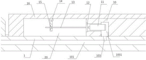
The displacement measuring device of the well drilling robot comprises a supporting rod (1), a limiter (2), a hydraulic pressure A (3), a hydraulic pressure B (16), a hydraulic pressure A piston (4), a hydraulic pressure B piston (10), a displacement sensor A (5), a displacement sensor B (11), a sealing baffle A (6), a sealing baffle B (12), a waveguide tube A (7), a waveguide tube B (13), a magnetic ring A (9), a magnetic ring B (15), a magnetic ring support plate A (8), a magnetic ring support plate B (14), a computer (17) and the well drilling robot (18);
the following steps: the hydraulic pressure A (3), the hydraulic pressure B (16), the hydraulic pressure A piston (4) and the hydraulic pressure B piston (10) are coaxially arranged on the supporting rod (1); the hydraulic A piston (4) is arranged in a cavity a between the hydraulic A (3) and the support rod (1); the hydraulic piston B (10) is arranged in a cavity B (20) between the hydraulic piston B (16) and the supporting rod (1), wherein the hydraulic piston B (10) is fixedly connected with the supporting rod (1);
the following steps: the magnetic ring A (9) is fixedly connected with the magnetic ring support plate A (8) through a screw, wherein the magnetic ring support plate A (8) is fixedly connected with the hydraulic pressure A (3) through a screw; the sealing baffle A (6) is connected with the displacement sensor A (5) through threads, wherein the sealing baffle A (6) and the hydraulic A piston (4) are fixed through solid glue; in the empty groove b of the hydraulic A piston (4), a limiter (2) is installed at the movement limit position of the hydraulic A piston (4) in a threaded mode, so that the function of measuring the displacement between the hydraulic A (3) and the hydraulic A piston (4) is realized;
the following steps: the magnetic ring B (15) is fixedly connected with the magnetic ring support plate B (14) through a screw, wherein the magnetic ring support plate B (14) is fixedly connected with the hydraulic pressure B (16) through a screw; the sealing baffle B (12) is connected with the displacement sensor B (11) through threads, wherein the sealing baffle B (12) and the hydraulic piston B (10) are fixed through solid glue, and the function of measuring the advancing displacement of the robot between the hydraulic piston B (16) and the hydraulic piston B (10) is realized.
The inner cylinder walls of the hydraulic pressure A (3) and the hydraulic pressure B (16) are provided with 2-4 grooves (301) which are uniformly distributed in the circumferential direction.
A circular groove (803) is milled on the magnetic ring support plate A (8) and the magnetic ring support plate B (14), a through hole (801) is arranged in the center of the groove, and 2-4 threaded holes (802) are uniformly arranged in the radial outer edge direction of the through hole (801) in the circumferential direction.
The sealing baffle A (6) and the sealing baffle B (12) are both provided with a sealing threaded hole (601) in the center, and 2-4 axisymmetric through holes (602) are arranged in the radial direction.
The hydraulic piston A (4) and the hydraulic piston B (10) are provided with 2-4 circular grooves (401) which are axially symmetrical by through holes (404) in the same external structure, the centers of the circular grooves (401) are provided with through holes (402), and 2-4 threaded holes (403) which are uniformly distributed are arranged in the radial direction;
the following steps: an arc-shaped groove (1001) is formed in the hydraulic piston B (10); the hydraulic A piston (4) is internally provided with an axial long groove (401).
The support rod (1) is axially provided with a through hole (101), and the support rod is radially provided with a through hole (103) and a threaded hole (102).
The displacement sensor A (5) and the displacement sensor B (11) are both magnetic displacement sensors, the displacement sensor A (5) is connected to the sealing baffle A (6) through threads and fixed on the hydraulic A piston (4), the magnetic ring A (9) of the displacement sensor A (5) is fixed on the magnetic ring support plate A (8) through solid glue or screws, the displacement sensor B (11) is fixed on the sealing baffle B (12) through threads and fixed on the hydraulic B piston (10), and the magnetic ring B (15) of the displacement sensor B (11) is fixed on the magnetic ring support plate B (14) through the solid glue screws.
The invention has the following advantages: the invention belongs to a drilling robot speed measuring device, which is simple, stable in measuring result and low in cost. Based on the speed measuring device of the drilling robot, the speed of the drilling robot can be measured and fed back instantly, data reference can be provided for automatic drilling of the drilling robot, the drilling robot is further promoted to be applied, and exploitation of unconventional oil and gas such as shale gas is promoted.
Drawings
FIG. 1 is a schematic structural diagram of a displacement measurement system of a drilling robot;
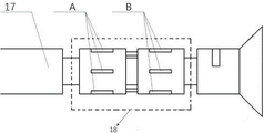
FIG. 2 is a structural diagram of a gripper translation hydraulic cylinder, which is a detailed structure of part A in FIG. 1;
fig. 3 is a structural diagram of a traveling hydraulic cylinder of the robot, which is a detailed structure of a part B in fig. 1;
FIG. 4 is a schematic view of a cylinder wall mounting structure of the hydraulic cylinder of FIGS. 1 and 2;
fig. 5 is a schematic structural view of a magnetic ring support plate in fig. 1 and 2;
FIG. 6 is a schematic view of the seal dam of FIGS. 1 and 2;
FIG. 7 is a schematic view of the piston of FIGS. 1 and 2;
fig. 8 is a schematic view of the installation position of the drilling tractor robot.
In the figure: 1-supporting rod, 2-limiter, 3-hydraulic A, 4-hydraulic A piston, 5-displacement sensor A, 6-sealing baffle A, 7-waveguide tube A, 8-magnetic ring support plate A, 9-magnetic ring A, 10-hydraulic B piston, 11-displacement sensor B, 12-sealing baffle B, 13-waveguide tube B, 14-magnetic ring support plate B, 15-magnetic ring B, 16-hydraulic B, 17-computer, 18-drilling robot, 101-through hole, 102-threaded hole, 103-through hole, 301-mounting groove, 401-mounting countersunk hole, 402-mounting hole, 403-threaded hole, 404-through hole, 601-through hole, 602-mounting hole, 801-through hole, 802-mounting hole, 803-mounting countersunk hole.
Detailed Description
The invention will be further described with reference to the accompanying drawings, without limiting the scope of the invention to the following:
the invention aims to provide a displacement measuring device of a drilling robot to make up for the blank of the prior art. In order to make the aforementioned objects, features and advantages of the present invention more comprehensible, the present invention is described in detail with reference to the accompanying drawings and the detailed description thereof.
As shown in fig. 1 to 7: after the drilling robot is installed on the ground, the well is put into the well and drilled, the well is pulled out after the well drilling is finished, and displacement data are extracted from the drilling robot (18);
the specific steps for mounting the displacement sensor are as follows: a magnetic ring B (15) is arranged on an installation countersunk hole (803) of a magnetic ring support plate B (14) by a screw, a magnetic ring A (9) is arranged on an installation countersunk hole (803) of a magnetic ring support plate A (8) by a screw, a sealing baffle A (6) is penetrated on a waveguide tube A (7), is arranged on a displacement sensor A (5) through mounting threads, a sealing baffle B (12) is penetrated on a waveguide tube B (13), the displacement sensor B (11) is installed on the displacement sensor B (11) through mounting threads, data lines of the displacement sensor A (5) and the displacement sensor B (11) are connected to a computer (17) of a drilling robot (18) through a line hole (101), a waveguide tube A (7) penetrates into a through hole (801) of a magnetic ring support plate A (8), a waveguide tube B (13) is penetrated into a through hole (801) of a magnetic ring support plate B (14), then the sealing baffle A (6) is arranged in an installation countersunk hole (401) of the piston (4) through solid glue, a magnetic ring support plate B (14) is arranged in a counter bore (401) of a piston (10) through solid glue, finally, a magnetic ring support plate B (14) is arranged in an arc-shaped groove (301) of a hydraulic pressure B (16) through a screw, a magnetic ring support plate A (8) is arranged in an arc-shaped groove (301) of the hydraulic pressure A (3) through a screw.
Claims (7)
1. Drilling traction robot displacement measurement device, its characterized in that: the device comprises a support rod (1), a limiter (2), a hydraulic pressure A (3), a hydraulic pressure B (16), a hydraulic pressure A piston (4), a hydraulic pressure B piston (10), a displacement sensor A (5), a displacement sensor B (11), a sealing baffle A (6), a sealing baffle B (12), a waveguide tube A (7), a waveguide tube B (13), a magnetic ring A (9), a magnetic ring B (15), a magnetic ring support plate A (8), a magnetic ring support plate B (14), a computer (17) and a drilling robot (18);
the hydraulic pressure A (3), the hydraulic pressure B (16), the hydraulic pressure A piston (4) and the hydraulic pressure B piston (10) are coaxially arranged on the supporting rod (1); the hydraulic A piston (4) is arranged in a cavity a between the hydraulic A (3) and the support rod (1); the hydraulic piston B (10) is arranged in a cavity B (20) between the hydraulic piston B (16) and the support rod (1), wherein the hydraulic piston B (10) is fixedly connected with the support rod (1);
the magnetic ring A (9) is fixedly connected with the magnetic ring support plate A (8) through a screw, wherein the magnetic ring support plate A (8) is fixedly connected with the hydraulic pressure A (3) through a screw; the sealing baffle A (6) is connected with the displacement sensor A (5) through threads, wherein the sealing baffle A (6) and the hydraulic A piston (4) are fixed through solid glue; in the empty groove b of the hydraulic A piston (4), a limiter (2) is installed at the movement limit position of the hydraulic A piston (4) in a threaded mode, so that the displacement measurement function between the hydraulic A (3) and the hydraulic A piston (4) is realized;
the magnetic ring B (15) is fixedly connected with the magnetic ring support plate B (14) through a screw, wherein the magnetic ring support plate B (14) is fixedly connected with the hydraulic pressure B (16) through a screw; the sealing baffle B (12) is connected with the displacement sensor B (11) through threads, wherein the sealing baffle B (12) and the hydraulic piston B (10) are fixed through solid glue, and the function of measuring the advancing displacement of the robot between the hydraulic piston B (16) and the hydraulic piston B (10) is realized;
based on the speed measuring device of the drilling robot, the speed of the drilling robot can be measured and fed back instantly, and data reference is provided for automatic drilling of the drilling robot.
2. The drilling traction robot displacement measurement device of claim 1, wherein: the inner cylinder walls of the hydraulic pressure A (3) and the hydraulic pressure B (16) are provided with 2-4 grooves (301) which are uniformly distributed in the circumferential direction.
3. The drilling tractor robot displacement measurement device of claim 1, wherein: countersunk holes (803) are milled on the magnetic ring support plate A (8) and the magnetic ring support plate B (14), a through hole (801) is arranged at the center of the groove, and 2-4 threaded holes (802) are uniformly arranged on the radial outer edge of the through hole (801) in the circumferential direction.
4. The drilling tractor robot displacement measurement device of claim 1, wherein: the center of each of the sealing baffle A (6) and the sealing baffle B (12) is provided with a sealing threaded hole (601), and 2-4 axisymmetric through holes (602) are arranged in the radial direction.
5. The drilling tractor robot displacement measurement device of claim 1, wherein: the hydraulic piston A (4) and the hydraulic piston B (10) are provided with 2-4 circular grooves (401) which are axially symmetrical by through holes (404) in the same external structure, the centers of the circular grooves (401) are provided with through holes (402), and 2-4 threaded holes (403) which are uniformly distributed are arranged in the radial direction;
an arc-shaped groove (1001) is formed in the hydraulic piston B (10); the hydraulic A piston (4) is internally provided with an axial long groove (401).
6. The drilling tractor robot displacement measurement device of claim 1, wherein: the support rod (1) is axially provided with a through hole (101), and the support rod is radially provided with a through hole (103) and a threaded hole (102).
7. The drilling traction robot displacement measurement device of claim 1, wherein: the displacement sensor A (5) and the displacement sensor B (11) are all magnetic displacement sensors, the displacement sensor A (5) is connected to the sealing baffle plate A (6) through threads and fixed on the hydraulic piston A (4), the magnetic ring A (9) of the displacement sensor A (5) is fixed on the magnetic ring support plate A (8) through solid glue or screws, the displacement sensor B (11) is fixed on the sealing baffle plate B (12) through threads and fixed on the hydraulic piston B (10), and the magnetic ring B (15) of the displacement sensor B (11) is fixed on the magnetic ring support plate B (14) through the solid glue screws.
Priority Applications (2)
| Application Number | Priority Date | Filing Date | Title |
|---|---|---|---|
| CN202110316450.1A CN113236233B (en) | 2021-03-25 | 2021-03-25 | Displacement measuring device for drilling traction robot |
| US17/387,956 US11781420B2 (en) | 2021-03-25 | 2021-07-28 | Displacement measuring device and speed measuring method of drilling traction robot |
Applications Claiming Priority (1)
| Application Number | Priority Date | Filing Date | Title |
|---|---|---|---|
| CN202110316450.1A CN113236233B (en) | 2021-03-25 | 2021-03-25 | Displacement measuring device for drilling traction robot |
Publications (2)
| Publication Number | Publication Date |
|---|---|
| CN113236233A CN113236233A (en) | 2021-08-10 |
| CN113236233B true CN113236233B (en) | 2022-10-14 |
Family
ID=77130726
Family Applications (1)
| Application Number | Title | Priority Date | Filing Date |
|---|---|---|---|
| CN202110316450.1A Active CN113236233B (en) | 2021-03-25 | 2021-03-25 | Displacement measuring device for drilling traction robot |
Country Status (1)
| Country | Link |
|---|---|
| CN (1) | CN113236233B (en) |
Citations (6)
| Publication number | Priority date | Publication date | Assignee | Title |
|---|---|---|---|---|
| WO2011051321A1 (en) * | 2009-10-30 | 2011-05-05 | Maersk Oil Qatar A/S | Downhole apparatus |
| CN203129999U (en) * | 2012-09-17 | 2013-08-14 | 重庆科技学院 | Control system of electronically controlled hydraulically driven coiled tubing downhole tractor |
| CN104060960A (en) * | 2014-06-25 | 2014-09-24 | 中国石油大学(北京) | Self-straightening type underground drawing device |
| RU2608136C1 (en) * | 2016-03-14 | 2017-01-16 | Анатолий Иванович Литвинов | Universal drilling robot |
| CN205909778U (en) * | 2016-01-21 | 2017-01-25 | 中国石油大学(北京) | Magnetostrictive displacement sensor sealing device for high pressure under water |
| CN107366523A (en) * | 2017-08-17 | 2017-11-21 | 西南石油大学 | A kind of coiled tubing draws robot |
Family Cites Families (8)
| Publication number | Priority date | Publication date | Assignee | Title |
|---|---|---|---|---|
| KR20140135689A (en) * | 2012-01-23 | 2014-11-26 | 트랜스오션 세드코 포렉스 벤쳐스 리미티드 | High definition drilling rate of penetration for marine drilling |
| AU2012370307B2 (en) * | 2012-02-13 | 2015-02-05 | Halliburton Energy Services, Inc. | Piston tractor system for use in subterranean wells |
| CN102777145B (en) * | 2012-08-16 | 2015-07-29 | 中国石油大学(北京) | A kind of Electro-hydraulic drive coiled tubing downhole tractor |
| NL2016859B1 (en) * | 2016-05-30 | 2017-12-11 | Engie Electroproject B V | A method of and a device for estimating down hole speed and down hole torque of borehole drilling equipment while drilling, borehole equipment and a computer program product. |
| BR102017017526B1 (en) * | 2017-08-15 | 2023-10-24 | Insfor - Innovative Solutions For Robotics Ltda - Me | AUTONOMOUS UNIT LAUNCHING SYSTEM FOR WORKING IN OIL AND GAS WELLS, AND METHOD OF INSTALLING AND UNINSTALLING A STANDALONE UNIT ON THE LAUNCHING SYSTEM |
| CN107701118A (en) * | 2017-08-21 | 2018-02-16 | 西南石油大学 | A kind of supporting construction of Microdrilling horizontal well coiled tubing drilling robot |
| CN107386971B (en) * | 2017-08-21 | 2019-05-17 | 西南石油大学 | A kind of coiled tubing drilling Robot experimental simulation device and method |
| CN112014221B (en) * | 2020-09-03 | 2022-02-15 | 西南石油大学 | Well drilling traction robot supporting mechanism testing arrangement |
-
2021
- 2021-03-25 CN CN202110316450.1A patent/CN113236233B/en active Active
Patent Citations (6)
| Publication number | Priority date | Publication date | Assignee | Title |
|---|---|---|---|---|
| WO2011051321A1 (en) * | 2009-10-30 | 2011-05-05 | Maersk Oil Qatar A/S | Downhole apparatus |
| CN203129999U (en) * | 2012-09-17 | 2013-08-14 | 重庆科技学院 | Control system of electronically controlled hydraulically driven coiled tubing downhole tractor |
| CN104060960A (en) * | 2014-06-25 | 2014-09-24 | 中国石油大学(北京) | Self-straightening type underground drawing device |
| CN205909778U (en) * | 2016-01-21 | 2017-01-25 | 中国石油大学(北京) | Magnetostrictive displacement sensor sealing device for high pressure under water |
| RU2608136C1 (en) * | 2016-03-14 | 2017-01-16 | Анатолий Иванович Литвинов | Universal drilling robot |
| CN107366523A (en) * | 2017-08-17 | 2017-11-21 | 西南石油大学 | A kind of coiled tubing draws robot |
Non-Patent Citations (2)
| Title |
|---|
| 井下探险救援机器人的设计;侯宪伦等;《煤矿机械》;20090815(第08期);全文 * |
| 新型井下细小管道检测系统的研究;任思等;《煤矿机械》;20080415(第04期);全文 * |
Also Published As
| Publication number | Publication date |
|---|---|
| CN113236233A (en) | 2021-08-10 |
Similar Documents
| Publication | Publication Date | Title |
|---|---|---|
| CN103850237B (en) | A kind of angle of throat cut-in type weak soil multiple position extensometer anchor head | |
| CN103015989B (en) | Downhole continuous wave mud pulse generator | |
| US11047183B2 (en) | Coiled tubing drilling robot, robot system and process parameter control method thereof | |
| CN112014221B (en) | Well drilling traction robot supporting mechanism testing arrangement | |
| CN201372792Y (en) | Instrument for measuring temperature and pressure while drilling in drilling well | |
| CN101696628B (en) | Steering bias tool and steering bias method | |
| CN104502182A (en) | Impact-rotary well drilling experiment device | |
| CN113236233B (en) | Displacement measuring device for drilling traction robot | |
| CN104389582A (en) | Well logging pushing and leaning device | |
| CN103821125B (en) | A kind of multi-functional multiple position extensometer anchor head | |
| CN204924522U (en) | A moment of torsion detection device for revolving dig rig unit head | |
| CN201314227Y (en) | Coiled tubing logging reel unit | |
| CN114059930A (en) | Controllable drill rod device for directional drilling of drill bit | |
| CN114199605B (en) | Horizontal drill string system dynamics simulation test bed and test method | |
| US11781420B2 (en) | Displacement measuring device and speed measuring method of drilling traction robot | |
| CN202392109U (en) | Two-stage seal structure for dynamic seal of underground dynamic drilling tool | |
| CN115450563A (en) | Anti-torque orientation tool experiment system and method | |
| CN103556981B (en) | A kind of drilling construction automatic monitoring system | |
| CN101328784A (en) | Drilling lead synchronous tracking screw thread pile machine with automatic control system | |
| CN112033658B (en) | System and method for testing supporting mechanism of drilling traction robot | |
| CN111350462B (en) | Deepwater surface layer conduit feeding tool release simulation experiment device and method | |
| CN113187461B (en) | Speed testing method for well drilling traction robot | |
| CN202578631U (en) | Control system for return pressure of wellhead of pressure-controlling drilling well | |
| CN202625682U (en) | Bit feed winch of deep-hole core drilling machine | |
| CN115874929B (en) | Double-push combined control rotary steering drilling system and drilling method for complex difficult-to-drill stratum |
Legal Events
| Date | Code | Title | Description |
|---|---|---|---|
| PB01 | Publication | ||
| PB01 | Publication | ||
| SE01 | Entry into force of request for substantive examination | ||
| SE01 | Entry into force of request for substantive examination | ||
| GR01 | Patent grant | ||
| GR01 | Patent grant |