CN112955195A - Joint to pump height level user interface, joint height auto calibration, and joint pressure estimation - Google Patents
Joint to pump height level user interface, joint height auto calibration, and joint pressure estimation Download PDFInfo
- Publication number
- CN112955195A CN112955195A CN201880056537.6A CN201880056537A CN112955195A CN 112955195 A CN112955195 A CN 112955195A CN 201880056537 A CN201880056537 A CN 201880056537A CN 112955195 A CN112955195 A CN 112955195A
- Authority
- CN
- China
- Prior art keywords
- fluid pump
- fluid
- pressure
- pump
- surgical site
- Prior art date
- Legal status (The legal status is an assumption and is not a legal conclusion. Google has not performed a legal analysis and makes no representation as to the accuracy of the status listed.)
- Pending
Links
Images


Classifications
-
- A—HUMAN NECESSITIES
- A61—MEDICAL OR VETERINARY SCIENCE; HYGIENE
- A61M—DEVICES FOR INTRODUCING MEDIA INTO, OR ONTO, THE BODY; DEVICES FOR TRANSDUCING BODY MEDIA OR FOR TAKING MEDIA FROM THE BODY; DEVICES FOR PRODUCING OR ENDING SLEEP OR STUPOR
- A61M1/00—Suction or pumping devices for medical purposes; Devices for carrying-off, for treatment of, or for carrying-over, body-liquids; Drainage systems
- A61M1/71—Suction drainage systems
- A61M1/73—Suction drainage systems comprising sensors or indicators for physical values
- A61M1/732—Visual indicating means for vacuum pressure
-
- A—HUMAN NECESSITIES
- A61—MEDICAL OR VETERINARY SCIENCE; HYGIENE
- A61B—DIAGNOSIS; SURGERY; IDENTIFICATION
- A61B17/00—Surgical instruments, devices or methods, e.g. tourniquets
- A61B17/00234—Surgical instruments, devices or methods, e.g. tourniquets for minimally invasive surgery
-
- A—HUMAN NECESSITIES
- A61—MEDICAL OR VETERINARY SCIENCE; HYGIENE
- A61M—DEVICES FOR INTRODUCING MEDIA INTO, OR ONTO, THE BODY; DEVICES FOR TRANSDUCING BODY MEDIA OR FOR TAKING MEDIA FROM THE BODY; DEVICES FOR PRODUCING OR ENDING SLEEP OR STUPOR
- A61M1/00—Suction or pumping devices for medical purposes; Devices for carrying-off, for treatment of, or for carrying-over, body-liquids; Drainage systems
- A61M1/71—Suction drainage systems
- A61M1/77—Suction-irrigation systems
-
- A—HUMAN NECESSITIES
- A61—MEDICAL OR VETERINARY SCIENCE; HYGIENE
- A61M—DEVICES FOR INTRODUCING MEDIA INTO, OR ONTO, THE BODY; DEVICES FOR TRANSDUCING BODY MEDIA OR FOR TAKING MEDIA FROM THE BODY; DEVICES FOR PRODUCING OR ENDING SLEEP OR STUPOR
- A61M3/00—Medical syringes, e.g. enemata; Irrigators
- A61M3/02—Enemata; Irrigators
- A61M3/0202—Enemata; Irrigators with electronic control means or interfaces
-
- A—HUMAN NECESSITIES
- A61—MEDICAL OR VETERINARY SCIENCE; HYGIENE
- A61M—DEVICES FOR INTRODUCING MEDIA INTO, OR ONTO, THE BODY; DEVICES FOR TRANSDUCING BODY MEDIA OR FOR TAKING MEDIA FROM THE BODY; DEVICES FOR PRODUCING OR ENDING SLEEP OR STUPOR
- A61M3/00—Medical syringes, e.g. enemata; Irrigators
- A61M3/02—Enemata; Irrigators
- A61M3/0204—Physical characteristics of the irrigation fluid, e.g. conductivity or turbidity
- A61M3/0208—Physical characteristics of the irrigation fluid, e.g. conductivity or turbidity before use
-
- A—HUMAN NECESSITIES
- A61—MEDICAL OR VETERINARY SCIENCE; HYGIENE
- A61M—DEVICES FOR INTRODUCING MEDIA INTO, OR ONTO, THE BODY; DEVICES FOR TRANSDUCING BODY MEDIA OR FOR TAKING MEDIA FROM THE BODY; DEVICES FOR PRODUCING OR ENDING SLEEP OR STUPOR
- A61M3/00—Medical syringes, e.g. enemata; Irrigators
- A61M3/02—Enemata; Irrigators
- A61M3/0204—Physical characteristics of the irrigation fluid, e.g. conductivity or turbidity
- A61M3/0216—Pressure
-
- A—HUMAN NECESSITIES
- A61—MEDICAL OR VETERINARY SCIENCE; HYGIENE
- A61M—DEVICES FOR INTRODUCING MEDIA INTO, OR ONTO, THE BODY; DEVICES FOR TRANSDUCING BODY MEDIA OR FOR TAKING MEDIA FROM THE BODY; DEVICES FOR PRODUCING OR ENDING SLEEP OR STUPOR
- A61M3/00—Medical syringes, e.g. enemata; Irrigators
- A61M3/02—Enemata; Irrigators
- A61M3/0233—Enemata; Irrigators characterised by liquid supply means, e.g. from pressurised reservoirs
- A61M3/0254—Enemata; Irrigators characterised by liquid supply means, e.g. from pressurised reservoirs the liquid being pumped
- A61M3/0258—Enemata; Irrigators characterised by liquid supply means, e.g. from pressurised reservoirs the liquid being pumped by means of electric pumps
-
- A—HUMAN NECESSITIES
- A61—MEDICAL OR VETERINARY SCIENCE; HYGIENE
- A61B—DIAGNOSIS; SURGERY; IDENTIFICATION
- A61B17/00—Surgical instruments, devices or methods, e.g. tourniquets
- A61B2017/00017—Electrical control of surgical instruments
- A61B2017/00115—Electrical control of surgical instruments with audible or visual output
-
- A—HUMAN NECESSITIES
- A61—MEDICAL OR VETERINARY SCIENCE; HYGIENE
- A61B—DIAGNOSIS; SURGERY; IDENTIFICATION
- A61B2217/00—General characteristics of surgical instruments
- A61B2217/002—Auxiliary appliance
- A61B2217/005—Auxiliary appliance with suction drainage system
-
- A—HUMAN NECESSITIES
- A61—MEDICAL OR VETERINARY SCIENCE; HYGIENE
- A61B—DIAGNOSIS; SURGERY; IDENTIFICATION
- A61B2217/00—General characteristics of surgical instruments
- A61B2217/002—Auxiliary appliance
- A61B2217/007—Auxiliary appliance with irrigation system
-
- A—HUMAN NECESSITIES
- A61—MEDICAL OR VETERINARY SCIENCE; HYGIENE
- A61M—DEVICES FOR INTRODUCING MEDIA INTO, OR ONTO, THE BODY; DEVICES FOR TRANSDUCING BODY MEDIA OR FOR TAKING MEDIA FROM THE BODY; DEVICES FOR PRODUCING OR ENDING SLEEP OR STUPOR
- A61M2205/00—General characteristics of the apparatus
- A61M2205/33—Controlling, regulating or measuring
- A61M2205/3331—Pressure; Flow
- A61M2205/3344—Measuring or controlling pressure at the body treatment site
-
- A—HUMAN NECESSITIES
- A61—MEDICAL OR VETERINARY SCIENCE; HYGIENE
- A61M—DEVICES FOR INTRODUCING MEDIA INTO, OR ONTO, THE BODY; DEVICES FOR TRANSDUCING BODY MEDIA OR FOR TAKING MEDIA FROM THE BODY; DEVICES FOR PRODUCING OR ENDING SLEEP OR STUPOR
- A61M2205/00—General characteristics of the apparatus
- A61M2205/33—Controlling, regulating or measuring
- A61M2205/3365—Rotational speed
-
- A—HUMAN NECESSITIES
- A61—MEDICAL OR VETERINARY SCIENCE; HYGIENE
- A61M—DEVICES FOR INTRODUCING MEDIA INTO, OR ONTO, THE BODY; DEVICES FOR TRANSDUCING BODY MEDIA OR FOR TAKING MEDIA FROM THE BODY; DEVICES FOR PRODUCING OR ENDING SLEEP OR STUPOR
- A61M2205/00—General characteristics of the apparatus
- A61M2205/50—General characteristics of the apparatus with microprocessors or computers
- A61M2205/502—User interfaces, e.g. screens or keyboards
Landscapes
- Health & Medical Sciences (AREA)
- Heart & Thoracic Surgery (AREA)
- Life Sciences & Earth Sciences (AREA)
- Public Health (AREA)
- Engineering & Computer Science (AREA)
- Veterinary Medicine (AREA)
- Biomedical Technology (AREA)
- Animal Behavior & Ethology (AREA)
- General Health & Medical Sciences (AREA)
- Hematology (AREA)
- Anesthesiology (AREA)
- Vascular Medicine (AREA)
- Surgery (AREA)
- Pulmonology (AREA)
- Nuclear Medicine, Radiotherapy & Molecular Imaging (AREA)
- Medical Informatics (AREA)
- Molecular Biology (AREA)
- External Artificial Organs (AREA)
- Infusion, Injection, And Reservoir Apparatuses (AREA)
- Surgical Instruments (AREA)
Abstract
Various exemplary methods, systems, and apparatus are provided for a joint-to-pump height level user interface, joint height auto-calibration, and joint pressure estimation. In general, an arthroscopic pump may be configured to estimate fluid pressure at a surgical site (e.g., at a joint) to provide an accurate indication of fluid pressure to a user. In an exemplary embodiment, the fluid pressure estimation is based on fluid pressure measurements at the pump, which are adjusted at the pump, for example, by a processor at the pump executing instructions stored in a memory at the pump using one or more control algorithms that adjust one or more factors, such as pressure losses in tubing and sheaths through which fluid flows between the pump and the surgical site, and height differences between the pump and the surgical site.
Description
Cross Reference to Related Applications
This application claims priority from U.S. provisional patent application 62/553,397 entitled "Methods, Systems, And Devices For Joint To Pump Elevation Level User Interfaces, Autocalization For Joint Elevation, And d Joint Pressure Estimation", filed on 9/1 in 2017, which is hereby incorporated by reference in its entirety.
Technical Field
The present disclosure relates generally to methods, systems, and devices for joint-to-pump height level user interface, joint height auto-calibration, and joint pressure estimation.
Background
Arthroscopic pumps are used in a variety of surgical procedures involving a variety of functions, such as soft tissue ablation, contouring, cutting, coagulation, and temperature control. During performance of a surgical procedure, an arthroscopic pump may provide fluid irrigation (inflow) to a surgical site, such as a patient's joint, and suction (outflow) of fluid from the surgical site. The pump may control fluid pressure at the joint to help provide joint expansion for access, maintain good visibility, and/or control bleeding. However, it is difficult for the pump to accurately measure the fluid pressure at the joint and, therefore, to accurately control the fluid pressure within the joint. For example, arthroscopic pumps typically do not measure the fluid pressure at the joint, but rather measure the fluid pressure at the pump and make adjustments to the pump pressure to estimate the fluid pressure at the joint. However, if the pump and patient joint are at different heights, such as if the pump is located on a cart at a height higher than the patient on the operating table, the fluid pressure measured at the pump will not accurately reflect the fluid pressure at the joint. Additionally, fluid travels between the pump and the joint through the tubing and sheath, but the pump may not accurately account for pressure losses in the tubing and sheath as the flow rate through the pump varies. Further, while the arthroscopic pump may provide an indication of the measured fluid pressure at the pump, the pump does not indicate to the surgeon that the measured fluid pressure is at the pump, and not at the joint, which may cause the surgeon to improperly control the fluid pressure at the joint to be too high or too low because the information provided to the surgeon does not accurately reflect the actual fluid pressure at the joint.
In some systems, fluid pressure may be measured at the joint, such as with a sensor positioned at the joint, but measuring the fluid pressure at the joint and communicating the measured fluid pressure to the pump typically results in a significant cost increase of the disposable tubing set, which is not feasible for most hospitals and surgeons.
Accordingly, there remains a need for improved devices, systems, and methods for arthroscopic pumps.
Disclosure of Invention
Generally, methods, systems, and devices are provided for a joint-to-pump height level user interface, for automatic joint height calibration, and for joint pressure estimation.
In one aspect, a surgical system is provided that includes, in one embodiment, a fluid pump system having a fluid pump. The fluid pump system is configured to pump fluid between the fluid pump and the surgical site through the tubing; measuring a fluid pressure at the fluid pump; determining an estimated pressure of the fluid at the surgical site by adjusting the measured pressure based on at least one of a height difference between the fluid pump and the surgical site and a type of tubing; and providing an indication of the estimated pressure of the fluid at the surgical site to a user of the fluid pump.
The surgical system may be varied in any number of ways. For example, the fluid pump system may be configured to provide an indication of the estimated pressure by displaying the estimated pressure on a display of the fluid pump system. As another example, a fluid pump system may be configured to measure a pressure of a fluid at a fluid pump by sensing a fluid pressure within a fluid chamber at the fluid pump.
As another example, the fluid pump system may be configured to receive an input indicative of a height difference from a user of the fluid pump. In at least some embodiments, the fluid pump system can be configured to automatically prompt a user to provide an input upon activation of the fluid pump, and/or the fluid pump system can be configured to provide a visual indication of the difference in height on a display at the pump.
As another example, a processor of the fluid pump system may be configured to automatically determine the height difference. In at least some embodiments, the processor may be configured to automatically determine the height difference upon activation of the fluid pump.
As another example, a fluid pump system may be configured to receive an input indicative of tubing from a user of the fluid pump. As another example, the fluid pump system may be configured to determine an estimated pressure of the fluid at the surgical site by measuring the pressure based on the speed of an irrigation motor at the fluid pump based on the type of tubing as determined. As another example, the fluid pump system may be configured to determine an estimated pressure of the fluid at the surgical site by measuring the pressure based on a speed of an irrigation motor at the pump, also based on the type of sheath associated with the tubing as determined. As another example, the fluid pump may be an arthroscopic fluid pump. As another example, the surgical site may be a joint of a patient. As another example, the fluid pump system may include a sensor configured to measure a pressure of the fluid at the fluid pump, and the fluid pump system may include a processor configured to receive the measured pressure from the sensor, determine an estimated pressure, and provide an indication to a user. As another example, the fluid pump may include a memory having an algorithm stored therein, and the fluid pump may include a processor configured to execute the algorithm to cause the processor to determine the estimated pressure.
As another example, determining an estimated pressure may include estimating a loss of inflow to the surgical site. In at least some embodiments, estimating the loss of inflow may include determining a speed of a motor of the fluid pump.
In another aspect, a surgical method is provided that in one embodiment includes pumping fluid between a fluid pump system and a surgical site through tubing; measuring a fluid pressure at a fluid pump of the fluid pump system; determining an estimated pressure of the fluid at the surgical site by adjusting the measured pressure based on at least one of a height difference between the fluid pump and the surgical site and a type of tubing; and providing an indication of the estimated pressure of the fluid at the surgical site to a user of the fluid pump.
The surgical method may have any number of variations. For example, providing an indication of the estimated pressure may include displaying the estimated pressure on a display of the fluid pump system. As another example, measuring the pressure of the fluid at the fluid pump may include sensing the fluid pressure within a fluid chamber at the fluid pump.
As another example, the method may include receiving, at the fluid pump system, an input indicative of the height difference from a user of the fluid pump. In at least some embodiments, the method can further include the fluid pump of the fluid pump system automatically prompting a user to provide an input upon activation of the fluid pump, and/or the input can change a visual representation of a relative elevation level of the fluid pump compared to the surgical site by changing a relative position of an icon representing a fill chamber of the fluid pump and an icon representing the surgical site.
As another example, the method may include a processor of the fluid pump system automatically determining the height difference. In at least some embodiments, the fluid pump system automatically determines the height difference upon activation of the fluid pump.
As another example, the method may include receiving an input from a user of the fluid pump indicative of the tubing. As another example, determining an estimated pressure of fluid at the surgical site based on the type of tubing may include determining a measured pressure based on a speed of an irrigation motor at the fluid pump. As another example, the fluid pump may be an arthroscopic fluid pump. As another example, the surgical site may be a joint of a patient. As another example, the fluid pump system may include a sensor that measures a pressure of the fluid at the fluid pump, and the fluid pump system may include a processor that receives the measured pressure from the sensor, determines an estimated pressure, and provides an indication to a user. As another example, the fluid pump system may include a memory having an algorithm stored therein, and the fluid pump system may include a processor configured to execute the algorithm such that the estimated pressure is determined.
As another example, determining an estimated pressure may include estimating a loss of inflow to the surgical site. In at least some embodiments, estimating the loss of inflow may include determining a speed of a motor of the fluid pump.
Drawings
The present invention will be more fully understood from the detailed description given below in conjunction with the accompanying drawings, in which:
FIG. 1 is a perspective view of one embodiment of an arthroscopic fluid pump;
FIG. 1A is a block diagram of the pump of FIG. 1 operably coupled to a surgical site via inflow tubing, a sheath, and outflow tubing;
FIG. 2 is a display of the fluid pump of FIG. 1 showing a height differential between the fluid pump and the patient;
FIG. 3 is a display of the fluid pump of FIG. 1 showing another height difference between the fluid pump and the patient;
FIG. 4 is a display of the fluid pump of FIG. 1 showing yet another height difference between the fluid pump and the patient;
FIG. 5 is a block diagram illustrating one embodiment of a fluid control algorithm of the pump of FIG. 1;
FIG. 6 is a graph showing fluid pressure versus time;
FIG. 7 is another graph showing fluid pressure versus time;
FIG. 8 is yet another graph showing fluid pressure versus time; and is
FIG. 9 is a graph illustrating fluid pressure at three different fluid flow rates.
Detailed Description
Certain exemplary embodiments will now be described to provide an overall understanding of the principles of the structure, function, manufacture, and use of the devices, systems, and methods disclosed herein. One or more examples of these embodiments are illustrated in the accompanying drawings. Those skilled in the art will understand that the devices, systems, and methods specifically described herein and illustrated in the accompanying drawings are non-limiting exemplary embodiments and that the scope of the present invention is defined solely by the claims. Features illustrated or described in connection with one exemplary embodiment may be combined with features of other embodiments. Such modifications and variations are intended to be included within the scope of the present invention.
Moreover, in the present disclosure, similarly named components in various embodiments typically have similar features, and thus, in a particular embodiment, each feature of each similarly named component is not necessarily fully set forth. Further, to the extent that linear or circular dimensions are used in the description of the disclosed systems, devices, and methods, such dimensions are not intended to limit the types of shapes that may be used in connection with such systems, devices, and methods. Those skilled in the art will recognize that the equivalent dimensions of such linear and circular dimensions can be readily determined for any geometric shape. The size and shape of the systems and devices and their components may depend at least on the anatomy of the subject in which the systems and devices are to be used, the size and shape of the components with which the systems and devices are to be used, and the methods and procedures in which the systems and devices are to be used.
Various exemplary methods, systems, and apparatus are provided for a joint-to-pump height level user interface, for automatic joint height calibration, and for joint pressure estimation. In general, arthroscopic pumps may be configured to estimate fluid pressure at a surgical site (e.g., at a joint) to provide users (e.g., surgeons and other medical personnel) with an accurate indication of fluid pressure. Thus, the fluid pressure at the surgical site can be accurately controlled to improve the surgical outcome. Fluid pressure at the surgical site can be accurately controlled even if an external flow device is inserted into the joint. Being able to accurately control the actual joint pressure to less than 60mmHg may help reduce the risk to the patient during surgery, such as by reducing the risk of extravasation due to excessive pressure. In an exemplary embodiment, the fluid pressure estimation is based on a fluid pressure measurement at the pump that is adjusted at the pump, for example, by a processor at the pump executing instructions stored in a memory at the pump using one or more control algorithms that adjust one or more factors. One of the factors that can be used to estimate the pressure of the fluid is the pressure loss in the tubing through which the fluid flows between the pump and the surgical site. Another of the factors that can be used to estimate fluid pressure is the height difference between the pump and the surgical site. Thus, no expensive and specialized equipment, such as tubing with built-in pressure sensors, is required to measure the fluid pressure at the surgical site itself. In other words, an accurate estimate of the fluid pressure at the surgical site may be determined even if the fluid pressure is measured only at the pump.
Estimating the losses (e.g., tubing loss and sheath loss) may allow the surgical site pressure to be controlled by adding it to the surgical site pressure set point (e.g., joint pressure set point) to update the pump pressure set point in the pump pressure control loop, which may be performed quickly. Thus, the control loop may provide a faster response and greater stability than directly controlling the surgical site pressure.
In certain surgical settings, the pump may have a height differential of a surgical site of six inches or more. In some cases, the height difference may be multiple feet, such as when the pump is positioned on a cart or rack above or below the patient level on the operating table. While pump instructions for use (IFU) may alert such pump positioning relative to the patient, the IFU may not always be followed, such as due to space constraints in the operating room or due to fixed cart heights. Generally, the difference in elevation between the surgical site and the pump results in an error of 22.4mmHg difference per foot. In other words, when the surgical site and the pump are at different heights, the fluid pressure measured at the pump will not accurately reflect the fluid pressure at the surgical site, with the greater the difference in height, the greater the difference between the fluid pressures. The ability to compensate for the height difference and provide an accurate estimate of the fluid pressure at the surgical site may greatly reduce errors.
Fig. 1 and 1A illustrate one embodiment of a pump system including an arthroscopic pump 10 configured to estimate fluid pressure at a surgical site 100. In an exemplary embodiment, the surgical site is at a joint, such as a knee or a shoulder. The pump 10 is configured to estimate the fluid pressure at the surgical site 100 in real time as the procedure is performed based on at least one of the height difference between the pump 10 and the surgical site 100 and the tubing through which the fluid flows between the pump 10 and the surgical site 100. In an exemplary embodiment, the pump 10 is configured to estimate pressure based on each of these two factors, but pressure may be estimated using only one of these factors. Each of the inflow tubing 102 and the outflow tubing 104 has an associated sheath, in which case the fluid pressure may be estimated based on the tubing 102 and its associated sheath.
The pump 10 may have a variety of configurations. In the illustrated embodiment, the pump 10 includes an irrigation pump configured to pump fluid to the surgical site and includes a suction pump configured to pump fluid from the surgical site. The pump 10 includes an articular inflow tubing to allow fluid flow between the pump 10 and the surgical site. Fig. 1A schematically illustrates the pump 10 operably connected to a surgical site 100 via inflow tubing 102, and shows the outflow tubing 104 returning to the suction pump of the pump system and then to the waste reservoir. The pump 10 also includes a fill chamber or reservoir 12 for smoothing fluid flow and providing pressure sensing through a sensing tube at the top of the reservoir 12. The pressure is sensed at the fluid level (e.g., water level) in the chamber 12, and thus the fluid level is the effective pressure sensor position.
The pump system further comprises a processor 22 configured to control the flush pump 10 and the suck pump. The pump 10 is configured to measure fluid pressure at the pump 10 based on the fluid pressure within the reservoir 12 and a pump motor speed (e.g., a speed of a motor 24 configured to drive the pump 10). The pump 10 is configured to adjust the pressure measured at the pump 10, as controlled by the processor 22, to determine an estimated pressure at the surgical site 100 using one or more control algorithms, as described further below. One or more control algorithms are stored in the memory 26 of the pump system and are executable by the processor 22. Processor 22 and memory 26 are shown as part of pump 10 in fig. 1A, but in other embodiments processor 22 and/or memory 26 may be located elsewhere in the pump system.
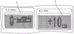
The pump system also includes a user interface configured to facilitate user interaction with the pump 10. The user interface includes a first display 14 configured to display joint pressure (in this illustrated embodiment in mmHg) in real-time with the pump 10 during performance of the surgical procedure. The fluid pressure on the first display 14 is shown as the estimated fluid pressure at the surgical site. The user interface also includes a second display 16 configured to display razor speed (in Revolutions Per Minute (RPM) in the illustrated embodiment).
The user interface also includes user controls configured to receive input from a user to control various pump functions. In the illustrated embodiment, the user controls include a depressible +/- (up/down) arrow button for controlling adjustment of information on the first display 14, and a depressible +/- (up/down) arrow button for controlling adjustment of information on the second display 16. In other embodiments, controls other than buttons may be used for one or both of the displays 14, 16, such as knobs, dials, joysticks, keypads, and the like. The suction pump FLOW rate is controlled by buttons labeled FLOW + and SHAVER. The FLOW + FLOW button is configured to be actuated with a foot pedal, and the SHAVER FLOW button is configured to be actuated when the razor is activated. The illustrated embodiment also includes a key to enable filling of the fill chamber 12 and a key to enable the SOLO (flush pump only) mode. In other implementations, one or both of the FLOW + and the SHAVER buttons may have another form, such as a knob, dial, joystick, or the like. The illustrated user interface also includes lights (e.g., Light Emitting Diodes (LEDs), etc.) that illuminate to indicate various conditions, such as blood stopped, high pressure warning, low pressure alarm, FLOW + FLOW rate, shut FLOW rate, enabled chamber filling, and pump on/off (run/stop).
As described above, the pump 10 may be configured to estimate pressure by taking into account the height difference between the pump 10 and the surgical site 100. The user interface in the illustrated embodiment is configured to facilitate compensation of the pump for height differences between the pump 10 and the surgical site 100.
The first display 14 is configured to show thereon a height icon indicating the relative height of the pump 10 and the patient. In the illustrated embodiment, the height icon conforms to the international organization for standardization (ISO) standard. As shown in fig. 1, the height icons include a pump fill chamber icon 18 in the form of a pump fill chamber with a fill level, and an ISO-approved patient icon 20 in the form of a patient on the operating table, although other forms of height icons may be used. The fill level indicates the level at which pressure is being sensed. For example, the fill chamber icon in fig. 1 shows a partially filled fill chamber, and it is this fill level that indicates the level at which pump pressure is sensed, e.g., a zero height level. The height difference between the pump 10 and the surgical site 100 is defined relative to zero level, wherein the surgical site 100 is at zero level (e.g., no height difference), below zero level, or above zero level.
The user interface is configured to allow the user to adjust the height difference using the +/-arrow associated with the first display 14 or alternatively the +/-arrow associated with the second display 16. For example, the height difference may be increased by a predetermined amount, e.g., 1cm, 2cm, 5cm, 10cm, etc., per one press of the + arrow, while the height difference may be decreased by a predetermined amount, e.g., 1cm, 2cm, 5cm, 10cm, etc., per one press of the-arrow. As the height difference is adjusted, the patient icon 20 moves up/down accordingly to provide a visual indication of the patient's height relative to the pump 10, and in particular relative to the fluid level in the fill chamber 12 of the pump 10. A positive non-zero height difference may be shown indicating that the fill level of the fill chamber 12 is above the surgical site 100 with the patient icon 20 in an upper position relative to the pump fill chamber icon 18 on the first display 14, and in particular relative to the fluid level indicia on the pump fill chamber icon 18. For example, fig. 2 shows a height difference of +10cm on the second display 16, and thus the patient icon 20 is in an upper position. A zero height difference may be shown with the patient icon 20 in an intermediate or neutral position relative to the pump fill chamber icon 18 on the first display 14, and in particular relative to the fluid level indicia on the pump fill chamber icon 18. For example, fig. 3 shows a height difference of 0cm on the second display 16, and thus the patient icon 20 is in a neutral or neutral position. A negative non-zero height difference may be shown indicating that the fill level of the fill chamber 12 is below the surgical site 100, with the patient icon 20 in a lower position relative to the pump fill chamber icon 18 on the first display 14, and in particular relative to the fluid level indicia on the pump fill chamber icon 18. For example, FIG. 4 shows a height difference of-10 cm on the second display 16, and thus the patient icon 20 is in a down position. The height difference may be higher than +10cm or less than-10 cm. For example, the height difference may be in the range of-60 cm to +90 cm.
The user interface is configured to show the height icon on the first display 14 when the pump 10 is started. For example, when power is turned on or when a run/stop button is pressed to signal the pump as "on," the user is prompted by an indication on one or both of the displays 14, 16 and/or by an audible indication through a speaker operatively connected to the pump 10 to confirm the relative heights of the surgical site 100 and the pump 10, and in particular the fill level of the pump chamber 12. The user confirms the relative height by adjusting the height as desired using the +/-arrow associated with the first display 14. Thus, the system may have accurate relative elevation information that processor 22 may later use in estimating the fluid pressure at surgical site 100. To accept the exact displayed height, the user presses the run/stop button. After the user manually enters the relative height, the first display 14 may continue to display the height icon or, conversely, the value of the fluid pressure, and the second display 16 may continue to display the height level or, conversely, the value of the razor speed. Pressing the run/stop button again will start the flush pump and the suck pump.
In at least some embodiments, a measuring device can be provided that is configured to facilitate a user's height differential input to the pump 10. For example, the pump 10 may have a mechanical measuring device, such as a ruler or the like, mounted thereon that a user may extend from the pump 10 to the surgical site 100 to allow the height of the surgical site to be measured using a line of sight. The mechanical measuring device mounted to the pump 10 may be retractable (similar to a tape measure) to facilitate storage and/or ease of use. As another example, pump 10 may have a mechanical measuring device mounted thereon as described above in addition to a horizontal laser light source to facilitate measurement of the height of the surgical site. The horizontal laser light source may be located, for example, at the end of a mechanical measuring device. As another example, a mechanical measuring device may be mounted on the cart on which the pump 10 is located and may extend from the cart to the surgical site to allow the height of the surgical site to be measured using a line of sight. The mechanical measuring device mounted to the cart may be retractable (similar to a tape measure) to facilitate storage and/or ease of use. As another example, pump 10 may have a slide mounted thereon with a linear encoder (magnetic or optical) mounted thereon. The slider may be selectively movable up and down by a user to align the end of the slider with the surgical site 100 using a line of sight to measure position via the linear encoder. As another example, pump 10 may have a slider as described above in addition to a horizontal laser light source to facilitate measuring the height of the surgical site. The slide is selectively movable up and down by a user to align a light beam (e.g., from a light source such as a laser spot) with the surgical site 100 by a linear encoder measuring position. As another example, the pump 10 may include a laser interferometer configured to measure a height difference between the pump 10 and the surgical site 100.
In at least some embodiments, rather than the user manually entering the height difference between the pump 10 and the surgical site 100, the pump 10 is configured to automatically determine the height distance between the pump 10 and the surgical site 100. In such embodiments, the pump 10 is configured to automatically determine the height upon start-up of the pump 10, such that the pump 10 has the relevant information needed to adjust the fluid pressure according to the height difference when the pump 10 is in use. Generally, to automatically determine the height, the pump 10 may be configured to zero the pressure at the level of the surgical site 100 to allow for compensation of any height differences between the surgical site 100 and the pump 10.
In one embodiment of the pump auto-calibration, the user will press the run/stop button on the user interface of the pump when the pump is started. An icon will then be shown on the first display 14 and/or the second display 16, indicating that a pressure calibration is to be performed. The user will hold the sheath connected to the end of the irrigation tubing 102 that extends between the pump 10 and the surgical site 100 at the level of the surgical site 100 (e.g., at a closed level) while the pump's irrigation valve is open and then press the run/stop button a second time. The pump 10 may be configured to prompt the user to hold the sheath at the level of the surgical site 100, such as by indication on one or both of the displays 14, 16 and/or by audible indication through a speaker operably connected to the pump 10. The pump's flush pump will then run in flow control mode for a sufficient time for it to fill. At this point, the pressure will be recorded for a predetermined amount of time, e.g., a few tenths of a second, and averaged. The flush flow will then be increased to provide another pressure data point. In the control algorithm, the pump 10 (e.g., its processor 22) will use these two pressure versus flow data points to estimate the height of the surgical site 100 relative to the pump 10 and the losses in tubing and sheath. The results of the algorithm will then be checked by the pump 10, for example by its processor 22, for limits, and if the results are within a predetermined tolerance, the pump 10 will end the auto-calibration. The end of the auto-calibration may be indicated by the pump 10, such as by an audible sound such as a beep and/or by a visual indication on one or both of the displays 14, 16. At the end of the auto-calibration, pressing the run/stop button will allow the user to adjust the joint pressure set point and the razor RPM speed set point. Depressing the run/stop button again will cause the pump 10 to start in its normal pressure regulation mode.
As described above, in addition to or instead of the pump 10 estimating pressure by considering the height difference between the pump 10 and the surgical site 100, the pump 10 may be configured to estimate pressure by considering the tubing 102, 104 and the sheath (if present) associated with the tubing 102, 104. In at least some embodiments, the pump 10 can be configured to allow a user to input tubing size and/or sheath size. Pump 10 may be configured to use the input dimensions in evaluating pressure loss compensation due to tubing and sheaths extending between pump 10 and surgical site 100. For example, the user interface of the pump may include a depressible sheath size control button that allows the user to adjust the sheath size up/down using the +/-arrow associated with the first display 14 or the second display 16 to reflect the current sheath size. Depressing the sheath size control button again may indicate acceptance of the displayed sheath size. Generally, although high flow sheaths are used in most arthroscopic procedures, smaller low flow sheaths are typically used for the facet joints and result in less accurate joint compression. Thus, allowing for the input of sheath size will allow the pump 10 to compensate for the sheath size when estimating the fluid pressure at the surgical site. In other embodiments, controls other than buttons may be used to enter sheath dimensions, such as knobs, dials, joysticks, keypads, and the like. In addition to or instead of the depressible sheath size control button, the user interface of the pump may include a depressible tubing size control button that allows the user to adjust tubing size up/down using the +/-arrow associated with first display 14 or second display 16 to reflect the current tubing size similar to that described above with respect to sheath size input. In other embodiments, controls other than buttons may be used to input tubing sizes, such as knobs, dials, joysticks, keypads, and the like.
One embodiment of a control algorithm that the pump system can use to estimate and control fluid pressure based on at least tubing and sheath losses is described below with reference to fig. 5. In an exemplary embodiment, the control algorithm is implemented in a combination of software and hardware, as shown in FIG. 5. The processor 22 is configured to execute control algorithms using various electronic components, such as rotary encoders, motor/gearboxes, pressure transducers, and pump components of the interface/control circuitry, as will be understood by those skilled in the art.
The algorithm first determines the pump pressure set point by estimating the tubing/sheath loss and adding this pressure drop to the joint pressure set point. A proportional Plus Integral (PI) controller is then used to control the pump pressure control loop. In addition, feed forward control from the suction pump is applied to anticipate sudden FLOW changes caused by the suction pump, such as FLOW + and SHAVER FLOW. The pressure control signal (from the PI controller) is combined with a feed forward signal from the suction pump to provide a speed command to the flush speed control loop. Fig. 5 shows a flush pump control circuit. The pump pressure set point is updated based on the estimated losses in the tubing and sheath. The estimation algorithm is updated periodically, rather than only when the flow pattern is changed. The periodicity may be any of a variety of predetermined intervals during use of the pump system, such as every X seconds, every Y minutes, and so forth.
The irrigation pump is configured to control pressure at a surgical site, for example, in a surgical joint performing arthroscopic surgery. However, the pressure is not measured at the joint, but only at the pump (e.g., in the fill chamber). Thus, to adjust joint pressure, the tubing/sheath loss is estimated and then added to the desired joint pressure Pjoint_cmdE.g., previously input to and/or as a preset pressure set point at the pump, to provide an updated pump pressure set point Ppump_cmd. The basis for adding the required joint pressure to the tubing/sheath loss to produce the updated pump pressure set point is that the pump pressure is equal to the joint pressure plus the tubing/sheath pressure drop. Tubing/sheath loss is a function of flow rate and therefore the speed of the flush motor of the pump system. Thus, the algorithm considers the motor speed ω to estimate the fluid pressure at the surgical site (e.g., at the joint). The estimation function for tubing/sheath loss is as follows, where ω ═ the angular velocity of the irrigation motor, in EncoderCnts/sec:
tubing/sheath loss [ mmHg]=4.70*ω2+.0091*ω+10
The angular velocity is calculated by using the washout encoder interrupt to determine the time between successive encoder pulses (as with the aspiration pump speed calculation). The velocity in the encoder counted per second is determined as follows:
speed 1406250[ clkPulses/sec ]/time between encoder pulses
When a timer interrupt does not occur for 5 milliseconds (10 times by a 2KHz timer interrupt), the speed will be reported as zero. The speed command is periodically updated to the output of a pressure loop PI (proportional, integral) controller for pressure regulation. The periodicity may be any of a variety of predetermined intervals during use of the pump system, such as every X seconds, every Y minutes, and so forth. The pressure control system uses the same speed control strategy as the suction pump, so the pressure controller (PI) provides speed commands to the speed control loop, and this update is used for controller calculations. The pressure loop PI controller is updated in a 2KHz timer interrupt that is also used to control the suction pump and razor. However, the pressure control algorithm is only updated every 64 times by an ISR (interrupt service routine) equal to 32 msec. This is sufficient due to the low closed loop bandwidth of the pressure control loop (i.e. <2 Hz). The PI controller formula is as follows, where Kp is 400, Ki is 0.222, Kd is 0.0, suction feed forward is the efficiency ratio of irrigation/aspiration pump:
setPointPumpPress=setPointJointPress+TubeSheathLoss
pcontrol ERROR Kp + SUM _ ERROR Ki-Kd dErr
VELCMD=Pcontrol+suctionFeedForward
To determine the updated pump pressure set point, the above equation is performed on a periodic predetermined basis (e.g., every 32msec), however, the TubeSheaththloss is only updated when the pump pressure has stabilized: if consecutive readings (at, for example, 500msec intervals) are within, for example, 2mmHg of each other.
The control loop is used to regulate the angular velocity of the suction (sucking) pump. Although both current feedback and speed feedback may be used, current feedback is not required. The controller output provides a PWM duty cycle to the motor using a 20KHz PWM output compare timer. In addition, a rate limit is provided to the PWM output so that the pulses ramp up at each transition to eliminate pulses at the motor at 2KHz, which is certainly audible. The rate limit is 10encoderCnts/2KHz interrupts. This means that the motor can reach maximum speed from zero in 0.8 seconds.
To improve response time to the SHAVER or FLOW + step change in the suction FLOW, a motor speed feed forward term is provided by the suction motor speed command. This helps the joint pressure control circuit anticipate local (i.e., FLOW disturbances caused by this pump), such as enabling or disabling the shunt or FLOW +. The ratio of suction speed feedforward to pump efficiency is multiplied to provide the correct steady state feedforward flow compensation in the irrigation pump to offset the additional flow in the suction pump. The ramp is applied to the suction feed forward speed in an attempt to counteract the speed ramp in the suction pump for the narrow or FLOW + FLOW. The feed forward suction rate compensation is combined with the output of the PID controller to provide a speed command to the speed control loop for the irrigation pump. The speed control loop is identical to the suction pump.
To prevent interference with the quick update of the displayed joint pressure, the displayed pressure is the estimated joint pressure updated every half second and additional filtering. The factory default joint pressure is set to 70mmHg, but the user can update the default values using a default menu. In other implementations, the factory default pressure is set to 50 mmHg.
The pump operation only requires the user to press the RUN button as long as the SOLO mode is not selected and the pump system door is closed. It is assumed that there is no malfunction such as overcurrent of the pump motor.
The flush (inflow) pump control uses a 2KHz timer and two separate control mechanisms pressure devices (two pressure sensors) and a speed device (high speed encoder) to control the motor speed. Fig. 5 shows the overall control loop for regulating the pressure.
When the pump is in RUN mode, the 2KHz loop performs the following operations in conjunction with the following state diagram processing: (1) the pressure controller uses readings from two analog channels (ADCs) to determine the difference between the pressure set point at the pressure sensor and the actual pressure reading. These signals are read together and averaged. Based on the difference (error), determining a new commanded PWM duty cycle count value that is fed into the speed portion of the motor control loop; and (2) the speed controller uses feedback from the high speed encoder (frequency) associated with the input capture compare timer. Using the command count determined in the previous step and the speed frequency of the motor, a new duty cycle for the PWM command input is calculated. The command is then fed into a PWM control register associated with the inflow motor. The PWM frequency is, for example, 20 Khz. The two pressure signals are monitored and compared to ensure that they are accurate within a predetermined threshold, e.g., +/-10% from each other.
Fig. 6-8 are graphs illustrating various scenarios in which the fluid pressure at the pump (e.g., the pressure measured at the fill level of the fill chamber of the pump) is different from the fluid pressure at the surgical site. These illustrated differences between the pressure at the pump and the pressure at the surgical site help to highlight the importance of estimating the pressure at the surgical site rather than considering the pressure measured at the pump to accurately reflect the pressure at the surgical site.
Fig. 6 is a graph showing pressure (in mmHg) versus time (in tenths of a second) in response to a 30mmHg step (70mmHg to 100mmHg) for pressure at the fluid pump and estimated pressure at the surgical site (in this embodiment, the joint) calculated by compensation of the fluid pump using elevation and loss of tubing/sheath. The graph shows that the pressure at the fluid pump is only slightly different from the estimated pressure at the surgical site.
Fig. 7 is a graph showing pressure (in mmHg) versus time (in tenths of a second) in response to a step change in flow rate of about 350mL/min resulting from internal razor suction source activity from about 5sec to about 250 sec. The graph shows that the pressure at the fluid pump increases with increasing flow rate to adjust the joint pressure when the razor is activated.
FIG. 8 is a graph showing pressure (in mmHg) versus time (in tenths of a second) in response to a step change in flow rate of about 350mL/min resulting from external suction source activity from about 5sec to about 25 sec. The graph illustrates a pressure increase at the fluid pump to regulate the pressure at the surgical site.
Fig. 9 is a graph illustrating the effectiveness of using the fluid pressure estimates described herein to control fluid pressure at a surgical site. The graph of fig. 9 shows the pressure (in mmHg) at three different fluid flow rates: idle traffic, medium traffic, and high traffic. The graph shows that by estimating the fluid pressure at the surgical site as described herein, the fluid pressure at the surgical site can be accurately controlled to allow the surgeon to use a lower pressure set point, which can help improve patient safety by maintaining the fluid pressure at a safe level, e.g., help reduce the risk of extravasation, or otherwise help improve patient safety. The pressure set point in this example is 50mmHg, and the site pressure in this example is 47mmHg at idle flow, 49mmHg at medium flow, and 43mmHg at high flow, which is a very good pressure regulation in such a flow range.
Those skilled in the art will appreciate that the present invention has application in conventional minimally invasive and open surgical instruments, as well as in robotic-assisted surgery.
Based on the above embodiments, one skilled in the art will recognize additional features and advantages of the present invention. Accordingly, the invention is not to be limited by what has been particularly shown and described, except as indicated by the appended claims. All publications and references cited herein are expressly incorporated herein by reference in their entirety.
Claims (33)
1. A surgical system, comprising:
a fluid pump system comprising a fluid pump, the fluid pump system configured to:
pumping fluid between the fluid pump and a surgical site through tubing,
measuring a pressure of the fluid at the fluid pump,
determining an estimated pressure of the fluid at the surgical site by adjusting the measured pressure based on at least one of a height difference between the fluid pump and the surgical site and a type of the tubing, an
Providing an indication of the estimated pressure of the fluid at the surgical site to a user of the fluid pump.
2. The system of claim 1, wherein the fluid pump system is configured to provide the indication of the estimated pressure by displaying the estimated pressure on a display of the fluid pump system.
3. The system of claim 1, wherein the fluid pump system is configured to measure the pressure of the fluid at the fluid pump by sensing a fluid pressure within a fluid chamber at the fluid pump.
4. The system of claim 1, wherein the fluid pump system is configured to receive an input indicative of the height difference from a user of the fluid pump.
5. The system of claim 4, wherein the fluid pump system is configured to automatically prompt the user to provide the input upon activation of the fluid pump.
6. The system of claim 4, wherein the fluid pump system is configured to provide a visual indication of the height difference on a display at the fluid pump.
7. The system of claim 1, wherein a processor of the fluid pump system is configured to automatically determine the height difference.
8. The system of claim 7, wherein the processor is configured to automatically determine the height difference upon activation of the fluid pump.
9. The system of claim 1, wherein the fluid pump system is configured to receive an input indicative of the tubing from a user of the fluid pump.
10. The system of claim 1, wherein the fluid pump system is configured to determine an estimated pressure of the fluid at the surgical site by measuring pressure based on a speed of an irrigation motor at the fluid pump based on the type of tubing as determined.
11. The system of claim 1, wherein the fluid pump system is configured to determine an estimated pressure of the fluid at the surgical site by measuring pressure based on a speed of an irrigation motor at the pump also based on a type of sheath associated with the tubing as determined.
12. The system of claim 1, wherein the fluid pump is an arthroscopic fluid pump.
13. The system of claim 1, wherein the surgical site is a joint of a patient.
14. The system of claim 1, wherein the fluid pump system comprises a sensor configured to measure the pressure of the fluid at the fluid pump, and the fluid pump system comprises a processor configured to receive the measured pressure from the sensor, determine the estimated pressure, and provide the indication to the user.
15. The system of claim 1, wherein the fluid pump system comprises a memory having an algorithm stored therein, and the fluid pump system comprises a processor configured to execute the algorithm and thereby cause the processor to determine the estimated pressure.
16. The system of claim 1, wherein determining the estimated pressure comprises estimating a loss at inflow of the surgical site.
17. The system of claim 16, wherein estimating the loss at inflow comprises determining a speed of a motor of the fluid pump.
18. A surgical method, comprising:
pumping fluid between the fluid pump system and the surgical site through the tubing;
measuring a fluid pressure at a fluid pump of the fluid pump system;
determining an estimated pressure of fluid at the surgical site by adjusting the measured pressure based on at least one of a height difference between the fluid pump and the surgical site and a type of the tubing; and
providing an indication of the estimated pressure of the fluid at the surgical site to a user of the fluid pump.
19. The method of claim 18, wherein providing the indication of the estimated pressure comprises displaying the estimated pressure on a display of the fluid pump system.
20. The method of claim 18, wherein measuring the pressure of the fluid at the fluid pump comprises sensing a fluid pressure within a fluid chamber at the fluid pump.
21. The method of claim 18, further comprising receiving, at the fluid pump system, an input indicative of the height difference from a user of the fluid pump.
22. The method of claim 21, further comprising the fluid pump system automatically prompting the user to provide the input upon activation of the fluid pump.
23. The method of claim 21, wherein the input changes a visual representation of a relative elevation level of the fluid pump compared to the surgical site by changing a relative position of an icon representing a fill chamber of the fluid pump and an icon representing the surgical site.
24. The method of claim 18, further comprising a processor of the fluid pump system automatically determining the height difference.
25. The method of claim 24, wherein the fluid pump system automatically determines the height difference upon activation of the fluid pump.
26. The method of claim 18, further comprising receiving an input from a user of the fluid pump indicating a type of the tubing.
27. The method of claim 18, wherein determining an estimated pressure of the fluid at the surgical site based on the type of tubing comprises determining the measured pressure based on a speed of an irrigation motor at the fluid pump.
28. The method of claim 18, wherein the fluid pump is an arthroscopic fluid pump.
29. The method of claim 18, wherein the surgical site is a joint of a patient.
30. The method of claim 18, wherein the fluid pump system comprises a sensor that measures the pressure of the fluid at the fluid pump, and the fluid pump system comprises a processor that receives the measured pressure from the sensor, determines the estimated pressure, and provides the indication to the user.
31. The method of claim 18, wherein the fluid pump system comprises a memory having an algorithm stored therein, and the fluid pump system comprises a processor configured to execute the algorithm, thereby causing the estimated pressure to be determined.
32. The method of claim 18, wherein determining the estimated pressure comprises estimating a loss at inflow of the surgical site.
33. The method of claim 32, wherein estimating the loss of inflow comprises determining a speed of a motor of the fluid pump.
Applications Claiming Priority (5)
| Application Number | Priority Date | Filing Date | Title |
|---|---|---|---|
| US201762553397P | 2017-09-01 | 2017-09-01 | |
| US62/553397 | 2017-09-01 | ||
| US16/114510 | 2018-08-28 | ||
| US16/114,510 US10874776B2 (en) | 2017-09-01 | 2018-08-28 | Methods, systems, and devices for joint to pump elevation level user interfaces, autocalibration for joint elevation, and joint pressure estimation |
| PCT/US2018/048814 WO2019046560A1 (en) | 2017-09-01 | 2018-08-30 | Joint to pump elevation level user interfaces, autocalibration for joint elevation, and joint pressure estimation |
Publications (1)
| Publication Number | Publication Date |
|---|---|
| CN112955195A true CN112955195A (en) | 2021-06-11 |
Family
ID=65517078
Family Applications (1)
| Application Number | Title | Priority Date | Filing Date |
|---|---|---|---|
| CN201880056537.6A Pending CN112955195A (en) | 2017-09-01 | 2018-08-30 | Joint to pump height level user interface, joint height auto calibration, and joint pressure estimation |
Country Status (7)
| Country | Link |
|---|---|
| US (2) | US10874776B2 (en) |
| EP (1) | EP3668565B1 (en) |
| JP (1) | JP7234215B2 (en) |
| CN (1) | CN112955195A (en) |
| AU (1) | AU2018324074B2 (en) |
| BR (1) | BR112020003881A2 (en) |
| WO (1) | WO2019046560A1 (en) |
Families Citing this family (7)
| Publication number | Priority date | Publication date | Assignee | Title |
|---|---|---|---|---|
| US10874776B2 (en) | 2017-09-01 | 2020-12-29 | Medos International Sarl | Methods, systems, and devices for joint to pump elevation level user interfaces, autocalibration for joint elevation, and joint pressure estimation |
| USD893547S1 (en) * | 2018-08-28 | 2020-08-18 | DePuy Synthes Products, Inc. | Surgical pump display screen or portion thereof with graphical user interface |
| USD896266S1 (en) * | 2018-11-05 | 2020-09-15 | Stryker Corporation | Display screen or portion thereof with graphical user interface |
| USD924922S1 (en) | 2019-07-12 | 2021-07-13 | GE Precision Healthcare LLC | Display screen with graphical user interface |
| US20230010088A1 (en) * | 2021-07-08 | 2023-01-12 | Medos International Sarl | Arthroscopic Pump Saline Management |
| WO2023281092A1 (en) | 2021-07-08 | 2023-01-12 | Medos International Sarl | Arthroscopic Pump Saline Management |
| USD1016854S1 (en) * | 2021-12-28 | 2024-03-05 | Stryker Corporation | Display screen or portion thereof with a bed bay identification icon |
Citations (6)
| Publication number | Priority date | Publication date | Assignee | Title |
|---|---|---|---|---|
| US5520638A (en) * | 1995-03-28 | 1996-05-28 | Arthrex, Inc. | Main pump tubing for arthroscopy infusion pump |
| US20100069937A1 (en) * | 2008-09-16 | 2010-03-18 | Seiko Epson Corporation | Fluid jet device, drive device of fluid jet device, surgical instrument, and method of driving fluid jet device |
| US20120138533A1 (en) * | 2010-12-01 | 2012-06-07 | Curtis James R | Dialysis system control system with user interface |
| US20150025450A1 (en) * | 2006-11-09 | 2015-01-22 | Abbott Medical Optics Inc. | Reversible Peristaltic Pump and Other Structures for Reflux in Eye Surgery |
| US20170157312A1 (en) * | 2012-04-05 | 2017-06-08 | Brady Woolford | Cassette for a surgical fluid management pump system |
| US20170209639A1 (en) * | 2014-07-23 | 2017-07-27 | Olympus Winter & Ibe Gmbh | Pump device |
Family Cites Families (59)
| Publication number | Priority date | Publication date | Assignee | Title |
|---|---|---|---|---|
| USD278804S (en) | 1981-07-23 | 1985-05-14 | Kabushiki Kaisha Suwa Seikosha | Design for display panel for electronic timepiece |
| USD276819S (en) | 1981-08-07 | 1984-12-18 | Mattel, Inc. | Video graphic figure font or the like |
| USD281081S (en) | 1981-09-15 | 1985-10-22 | Ruedi Zwissler | Font of symbols |
| US5315530A (en) | 1990-09-10 | 1994-05-24 | Rockwell International Corporation | Real-time control of complex fluid systems using generic fluid transfer model |
| DE69228410T2 (en) * | 1991-08-21 | 1999-07-08 | Smith & Nephew Inc | Liquid treatment system |
| US6024720A (en) | 1995-07-18 | 2000-02-15 | Aquarius Medical Corporation | Fluid management system for arthroscopic surgery |
| US5830180A (en) | 1996-07-17 | 1998-11-03 | Aquarius Medical Corporation | Fluid management system for arthroscopic surgery |
| US6394974B1 (en) | 1997-01-22 | 2002-05-28 | Allergan Sales, Inc. | Power mode phaco |
| US7010369B2 (en) | 1997-11-07 | 2006-03-07 | Hill-Rom Services, Inc. | Medical equipment controller |
| US6176847B1 (en) | 1999-05-14 | 2001-01-23 | Circon Corporation | Surgical irrigation system incorporating flow sensor device |
| US6503062B1 (en) | 2000-07-10 | 2003-01-07 | Deka Products Limited Partnership | Method for regulating fluid pump pressure |
| EP1421458B1 (en) | 2001-08-03 | 2010-04-07 | Hill-Rom Services, Inc. | Patient point-of-care computer system |
| US20050092523A1 (en) | 2003-10-30 | 2005-05-05 | Power Chokes, L.P. | Well pressure control system |
| US7945452B2 (en) | 2005-04-11 | 2011-05-17 | Hospira, Inc. | User interface improvements for medical devices |
| US7604610B2 (en) * | 2005-06-13 | 2009-10-20 | Smith & Nephew, Inc. | Surgical fluid management |
| EP1736700B1 (en) | 2005-06-23 | 2012-09-12 | General Electric Company | Fastening means for a patient monitor |
| US7981073B2 (en) * | 2006-03-30 | 2011-07-19 | Moellstam Anders | Method and device for irrigation of body cavities |
| WO2008042790A1 (en) | 2006-09-29 | 2008-04-10 | Draeger Medical Systems, Inc. | System for processing, deriving, and displaying relationships among patient medical parameters |
| US8424362B2 (en) | 2006-11-09 | 2013-04-23 | Abbott Medical Optics Inc. | Methods and apparatus for calibrating a vacuum component of a phacoemulsification system |
| US7628054B2 (en) | 2006-11-09 | 2009-12-08 | Abbott Medical Optics Inc. | Calibration utility for non-linear measurement system |
| US7510542B2 (en) | 2006-12-20 | 2009-03-31 | Linvatec Corporation | Dual pump irrigation/aspiration system and method for determining joint pressure |
| USD572725S1 (en) | 2007-08-13 | 2008-07-08 | Alert Life Sciences Computing, S.A. | Icon for a portion of a display screen |
| USD572724S1 (en) | 2007-08-13 | 2008-07-08 | Alert Life Sciences Computing, S.A. | Icon for a portion of a display screen |
| US9050471B2 (en) | 2008-07-11 | 2015-06-09 | Medtronic, Inc. | Posture state display on medical device user interface |
| US9289541B2 (en) | 2008-08-22 | 2016-03-22 | Medtronic, Inc. | Surgical fluid management system |
| USD611498S1 (en) | 2009-01-26 | 2010-03-09 | A-Dec, Inc. | Controller for a bed or chair with symbol set |
| EP2485637A4 (en) | 2009-10-08 | 2015-01-07 | Univ Michigan Office Of Technology Transfer | Real-time visual alert display |
| US9089367B2 (en) | 2010-04-08 | 2015-07-28 | Alcon Research, Ltd. | Patient eye level touch control |
| US9492341B2 (en) | 2010-10-08 | 2016-11-15 | Hill-Rom Services, Inc. | Hospital bed with graphical user interface having advanced functionality |
| US9162023B2 (en) | 2011-05-05 | 2015-10-20 | Carefusion 303, Inc. | Automated pressure limit setting method and apparatus |
| US20120302941A1 (en) | 2011-05-23 | 2012-11-29 | Dan Teodorescu | Phacoemulsification systems and associated user-interfaces and methods |
| US9597445B2 (en) | 2011-11-11 | 2017-03-21 | Abbott Medical Optics Inc. | Fluid management system for use in a medical procedure |
| US9289110B2 (en) | 2012-04-05 | 2016-03-22 | Stryker Corporation | Control for surgical fluid management pump system |
| WO2013176713A1 (en) | 2012-05-25 | 2013-11-28 | Abbott Medical Optics, Inc. | Surgical handpiece having directional fluid control capabilities |
| PL2674176T3 (en) | 2012-06-12 | 2015-04-30 | Eos Gmbh | Device for adjusting irrigation pressure during eye operations |
| US9044361B2 (en) | 2012-07-24 | 2015-06-02 | Hill-Rom Services, Inc. | Proxy caregiver interface |
| US9681982B2 (en) | 2012-12-17 | 2017-06-20 | Alcon Research, Ltd. | Wearable user interface for use with ocular surgical console |
| USD759063S1 (en) | 2013-02-14 | 2016-06-14 | Healthmate International, LLC | Display screen with graphical user interface for an electrotherapy device |
| US20140278524A1 (en) | 2013-03-12 | 2014-09-18 | Cerner Innovation, Inc. | Associating patients and medical devices with a mobile device via bluetooth |
| US9295582B2 (en) | 2013-03-13 | 2016-03-29 | Abbott Medical Optics Inc. | Fluidics adjustment techniques for use in a surgical procedure |
| US9205186B2 (en) | 2013-03-14 | 2015-12-08 | Abbott Medical Optics Inc. | System and method for providing pressurized infusion |
| US9433723B2 (en) | 2013-03-14 | 2016-09-06 | Abbott Medical Optics Inc. | System and method for providing pressurized infusion |
| WO2015026457A1 (en) | 2013-08-22 | 2015-02-26 | Novartis Ag | Graphical user interface for surgical console |
| US9830424B2 (en) | 2013-09-18 | 2017-11-28 | Hill-Rom Services, Inc. | Bed/room/patient association systems and methods |
| USD742917S1 (en) | 2013-10-11 | 2015-11-10 | Microsoft Corporation | Display screen with transitional graphical user interface |
| SE537628C2 (en) | 2013-11-08 | 2015-08-18 | Bonvisi Ab | Device for irrigation and insufflation with blood pressure dependent pressure control |
| USD738928S1 (en) | 2013-12-02 | 2015-09-15 | Medtronic, Inc. | Display screen with icon |
| USD738929S1 (en) | 2013-12-02 | 2015-09-15 | Medtronic, Inc. | Display screen with icon |
| US20150277703A1 (en) | 2014-02-25 | 2015-10-01 | Stephen Rhett Davis | Apparatus for digital signage alerts |
| US9942739B2 (en) | 2014-09-19 | 2018-04-10 | Rapidsos, Inc. | Method and system for emergency call management |
| USD772905S1 (en) | 2014-11-14 | 2016-11-29 | Volvo Car Corporation | Display screen with graphical user interface |
| US10076593B2 (en) | 2015-05-26 | 2018-09-18 | Stryker Corporation | Pressure control algorithm for high resistance hardware |
| US10293099B2 (en) | 2015-05-26 | 2019-05-21 | Stryker Corporation | Pump and means for controlling a pump |
| USD800162S1 (en) | 2016-03-22 | 2017-10-17 | Teletracking Technologies, Inc. | Display screen with graphical user interface icon |
| US11172892B2 (en) | 2017-01-04 | 2021-11-16 | Hill-Rom Services, Inc. | Patient support apparatus having vital signs monitoring and alerting |
| US10874776B2 (en) | 2017-09-01 | 2020-12-29 | Medos International Sarl | Methods, systems, and devices for joint to pump elevation level user interfaces, autocalibration for joint elevation, and joint pressure estimation |
| USD877755S1 (en) | 2018-03-12 | 2020-03-10 | Minebea Mitsumi Inc. | Display screen with graphical user interface |
| USD893547S1 (en) | 2018-08-28 | 2020-08-18 | DePuy Synthes Products, Inc. | Surgical pump display screen or portion thereof with graphical user interface |
| USD881237S1 (en) | 2018-09-14 | 2020-04-14 | Fujitsu Limited | Display screen with icons |
-
2018
- 2018-08-28 US US16/114,510 patent/US10874776B2/en active Active
- 2018-08-30 CN CN201880056537.6A patent/CN112955195A/en active Pending
- 2018-08-30 WO PCT/US2018/048814 patent/WO2019046560A1/en unknown
- 2018-08-30 BR BR112020003881-4A patent/BR112020003881A2/en unknown
- 2018-08-30 AU AU2018324074A patent/AU2018324074B2/en active Active
- 2018-08-30 JP JP2020512400A patent/JP7234215B2/en active Active
- 2018-08-30 EP EP18850625.7A patent/EP3668565B1/en active Active
-
2020
- 2020-12-02 US US17/109,399 patent/US11878103B2/en active Active
Patent Citations (6)
| Publication number | Priority date | Publication date | Assignee | Title |
|---|---|---|---|---|
| US5520638A (en) * | 1995-03-28 | 1996-05-28 | Arthrex, Inc. | Main pump tubing for arthroscopy infusion pump |
| US20150025450A1 (en) * | 2006-11-09 | 2015-01-22 | Abbott Medical Optics Inc. | Reversible Peristaltic Pump and Other Structures for Reflux in Eye Surgery |
| US20100069937A1 (en) * | 2008-09-16 | 2010-03-18 | Seiko Epson Corporation | Fluid jet device, drive device of fluid jet device, surgical instrument, and method of driving fluid jet device |
| US20120138533A1 (en) * | 2010-12-01 | 2012-06-07 | Curtis James R | Dialysis system control system with user interface |
| US20170157312A1 (en) * | 2012-04-05 | 2017-06-08 | Brady Woolford | Cassette for a surgical fluid management pump system |
| US20170209639A1 (en) * | 2014-07-23 | 2017-07-27 | Olympus Winter & Ibe Gmbh | Pump device |
Also Published As
| Publication number | Publication date |
|---|---|
| US20190070343A1 (en) | 2019-03-07 |
| US20210085840A1 (en) | 2021-03-25 |
| AU2018324074B2 (en) | 2022-12-01 |
| EP3668565A4 (en) | 2021-04-28 |
| JP2020532365A (en) | 2020-11-12 |
| WO2019046560A1 (en) | 2019-03-07 |
| BR112020003881A2 (en) | 2020-10-06 |
| US11878103B2 (en) | 2024-01-23 |
| US10874776B2 (en) | 2020-12-29 |
| AU2018324074A1 (en) | 2020-04-02 |
| EP3668565A1 (en) | 2020-06-24 |
| EP3668565C0 (en) | 2024-02-07 |
| EP3668565B1 (en) | 2024-02-07 |
| JP7234215B2 (en) | 2023-03-07 |
Similar Documents
| Publication | Publication Date | Title |
|---|---|---|
| CN112955195A (en) | Joint to pump height level user interface, joint height auto calibration, and joint pressure estimation | |
| US9889246B2 (en) | Cassette for a surgical fluid management pump system | |
| US9289110B2 (en) | Control for surgical fluid management pump system | |
| US9962472B2 (en) | In-joint sensor for a surgical fluid management pump system | |
| US11235096B2 (en) | Pump and means for controlling a pump | |
| KR20160064118A (en) | System and method of controlling a robotic system for manipulating anatomy of a patient during a surgical procedure | |
| JP2020531155A (en) | Arthroscopy equipment and arthroscopy method | |
| EP3485795B1 (en) | Systems of fluid control in surgical procedures | |
| JP2006325750A (en) | Blood circulation system and its controller | |
| US10076593B2 (en) | Pressure control algorithm for high resistance hardware | |
| US20230320897A1 (en) | Automated phacoemulsification | |
| US11925360B2 (en) | Method for preventing kinked tubing in an arthroscopic irrigation pump | |
| US20230010088A1 (en) | Arthroscopic Pump Saline Management | |
| US20240009378A1 (en) | Arthroscopic pump saline management | |
| WO2023281092A1 (en) | Arthroscopic Pump Saline Management | |
| US11992594B2 (en) | Blood circulation system | |
| CN115176318A (en) | Adaptive pressure control filter for fluid management systems | |
| WO2023111067A1 (en) | Surgical Device Activation Detection Using Current Sensing |
Legal Events
| Date | Code | Title | Description |
|---|---|---|---|
| PB01 | Publication | ||
| PB01 | Publication | ||
| SE01 | Entry into force of request for substantive examination | ||
| SE01 | Entry into force of request for substantive examination |