CN112933391A - Tip-loaded microneedle array for percutaneous insertion - Google Patents
Tip-loaded microneedle array for percutaneous insertion Download PDFInfo
- Publication number
- CN112933391A CN112933391A CN202110125343.0A CN202110125343A CN112933391A CN 112933391 A CN112933391 A CN 112933391A CN 202110125343 A CN202110125343 A CN 202110125343A CN 112933391 A CN112933391 A CN 112933391A
- Authority
- CN
- China
- Prior art keywords
- microneedles
- microneedle array
- microneedle
- cmc
- array
- Prior art date
- Legal status (The legal status is an assumption and is not a legal conclusion. Google has not performed a legal analysis and makes no representation as to the accuracy of the status listed.)
- Pending
Links
Images


Classifications
-
- B—PERFORMING OPERATIONS; TRANSPORTING
- B29—WORKING OF PLASTICS; WORKING OF SUBSTANCES IN A PLASTIC STATE IN GENERAL
- B29C—SHAPING OR JOINING OF PLASTICS; SHAPING OF MATERIAL IN A PLASTIC STATE, NOT OTHERWISE PROVIDED FOR; AFTER-TREATMENT OF THE SHAPED PRODUCTS, e.g. REPAIRING
- B29C67/00—Shaping techniques not covered by groups B29C39/00 - B29C65/00, B29C70/00 or B29C73/00
-
- A—HUMAN NECESSITIES
- A61—MEDICAL OR VETERINARY SCIENCE; HYGIENE
- A61K—PREPARATIONS FOR MEDICAL, DENTAL OR TOILETRY PURPOSES
- A61K9/00—Medicinal preparations characterised by special physical form
- A61K9/0012—Galenical forms characterised by the site of application
- A61K9/0019—Injectable compositions; Intramuscular, intravenous, arterial, subcutaneous administration; Compositions to be administered through the skin in an invasive manner
- A61K9/0021—Intradermal administration, e.g. through microneedle arrays, needleless injectors
-
- A—HUMAN NECESSITIES
- A61—MEDICAL OR VETERINARY SCIENCE; HYGIENE
- A61L—METHODS OR APPARATUS FOR STERILISING MATERIALS OR OBJECTS IN GENERAL; DISINFECTION, STERILISATION OR DEODORISATION OF AIR; CHEMICAL ASPECTS OF BANDAGES, DRESSINGS, ABSORBENT PADS OR SURGICAL ARTICLES; MATERIALS FOR BANDAGES, DRESSINGS, ABSORBENT PADS OR SURGICAL ARTICLES
- A61L31/00—Materials for other surgical articles, e.g. stents, stent-grafts, shunts, surgical drapes, guide wires, materials for adhesion prevention, occluding devices, surgical gloves, tissue fixation devices
- A61L31/04—Macromolecular materials
- A61L31/042—Polysaccharides
-
- A—HUMAN NECESSITIES
- A61—MEDICAL OR VETERINARY SCIENCE; HYGIENE
- A61L—METHODS OR APPARATUS FOR STERILISING MATERIALS OR OBJECTS IN GENERAL; DISINFECTION, STERILISATION OR DEODORISATION OF AIR; CHEMICAL ASPECTS OF BANDAGES, DRESSINGS, ABSORBENT PADS OR SURGICAL ARTICLES; MATERIALS FOR BANDAGES, DRESSINGS, ABSORBENT PADS OR SURGICAL ARTICLES
- A61L31/00—Materials for other surgical articles, e.g. stents, stent-grafts, shunts, surgical drapes, guide wires, materials for adhesion prevention, occluding devices, surgical gloves, tissue fixation devices
- A61L31/14—Materials characterised by their function or physical properties, e.g. injectable or lubricating compositions, shape-memory materials, surface modified materials
- A61L31/16—Biologically active materials, e.g. therapeutic substances
-
- A—HUMAN NECESSITIES
- A61—MEDICAL OR VETERINARY SCIENCE; HYGIENE
- A61M—DEVICES FOR INTRODUCING MEDIA INTO, OR ONTO, THE BODY; DEVICES FOR TRANSDUCING BODY MEDIA OR FOR TAKING MEDIA FROM THE BODY; DEVICES FOR PRODUCING OR ENDING SLEEP OR STUPOR
- A61M37/00—Other apparatus for introducing media into the body; Percutany, i.e. introducing medicines into the body by diffusion through the skin
- A61M37/0015—Other apparatus for introducing media into the body; Percutany, i.e. introducing medicines into the body by diffusion through the skin by using microneedles
-
- B—PERFORMING OPERATIONS; TRANSPORTING
- B23—MACHINE TOOLS; METAL-WORKING NOT OTHERWISE PROVIDED FOR
- B23C—MILLING
- B23C3/00—Milling particular work; Special milling operations; Machines therefor
- B23C3/16—Working surfaces curved in two directions
- B23C3/20—Working surfaces curved in two directions for shaping dies
-
- A—HUMAN NECESSITIES
- A61—MEDICAL OR VETERINARY SCIENCE; HYGIENE
- A61B—DIAGNOSIS; SURGERY; IDENTIFICATION
- A61B17/00—Surgical instruments, devices or methods, e.g. tourniquets
- A61B2017/00526—Methods of manufacturing
-
- A—HUMAN NECESSITIES
- A61—MEDICAL OR VETERINARY SCIENCE; HYGIENE
- A61L—METHODS OR APPARATUS FOR STERILISING MATERIALS OR OBJECTS IN GENERAL; DISINFECTION, STERILISATION OR DEODORISATION OF AIR; CHEMICAL ASPECTS OF BANDAGES, DRESSINGS, ABSORBENT PADS OR SURGICAL ARTICLES; MATERIALS FOR BANDAGES, DRESSINGS, ABSORBENT PADS OR SURGICAL ARTICLES
- A61L2300/00—Biologically active materials used in bandages, wound dressings, absorbent pads or medical devices
- A61L2300/80—Biologically active materials used in bandages, wound dressings, absorbent pads or medical devices characterised by a special chemical form
- A61L2300/802—Additives, excipients, e.g. cyclodextrins, fatty acids, surfactants
-
- A—HUMAN NECESSITIES
- A61—MEDICAL OR VETERINARY SCIENCE; HYGIENE
- A61L—METHODS OR APPARATUS FOR STERILISING MATERIALS OR OBJECTS IN GENERAL; DISINFECTION, STERILISATION OR DEODORISATION OF AIR; CHEMICAL ASPECTS OF BANDAGES, DRESSINGS, ABSORBENT PADS OR SURGICAL ARTICLES; MATERIALS FOR BANDAGES, DRESSINGS, ABSORBENT PADS OR SURGICAL ARTICLES
- A61L2400/00—Materials characterised by their function or physical properties
- A61L2400/18—Modification of implant surfaces in order to improve biocompatibility, cell growth, fixation of biomolecules, e.g. plasma treatment
-
- A—HUMAN NECESSITIES
- A61—MEDICAL OR VETERINARY SCIENCE; HYGIENE
- A61M—DEVICES FOR INTRODUCING MEDIA INTO, OR ONTO, THE BODY; DEVICES FOR TRANSDUCING BODY MEDIA OR FOR TAKING MEDIA FROM THE BODY; DEVICES FOR PRODUCING OR ENDING SLEEP OR STUPOR
- A61M37/00—Other apparatus for introducing media into the body; Percutany, i.e. introducing medicines into the body by diffusion through the skin
- A61M37/0015—Other apparatus for introducing media into the body; Percutany, i.e. introducing medicines into the body by diffusion through the skin by using microneedles
- A61M2037/0023—Drug applicators using microneedles
-
- A—HUMAN NECESSITIES
- A61—MEDICAL OR VETERINARY SCIENCE; HYGIENE
- A61M—DEVICES FOR INTRODUCING MEDIA INTO, OR ONTO, THE BODY; DEVICES FOR TRANSDUCING BODY MEDIA OR FOR TAKING MEDIA FROM THE BODY; DEVICES FOR PRODUCING OR ENDING SLEEP OR STUPOR
- A61M37/00—Other apparatus for introducing media into the body; Percutany, i.e. introducing medicines into the body by diffusion through the skin
- A61M37/0015—Other apparatus for introducing media into the body; Percutany, i.e. introducing medicines into the body by diffusion through the skin by using microneedles
- A61M2037/0046—Solid microneedles
-
- A—HUMAN NECESSITIES
- A61—MEDICAL OR VETERINARY SCIENCE; HYGIENE
- A61M—DEVICES FOR INTRODUCING MEDIA INTO, OR ONTO, THE BODY; DEVICES FOR TRANSDUCING BODY MEDIA OR FOR TAKING MEDIA FROM THE BODY; DEVICES FOR PRODUCING OR ENDING SLEEP OR STUPOR
- A61M37/00—Other apparatus for introducing media into the body; Percutany, i.e. introducing medicines into the body by diffusion through the skin
- A61M37/0015—Other apparatus for introducing media into the body; Percutany, i.e. introducing medicines into the body by diffusion through the skin by using microneedles
- A61M2037/0053—Methods for producing microneedles
-
- A—HUMAN NECESSITIES
- A61—MEDICAL OR VETERINARY SCIENCE; HYGIENE
- A61M—DEVICES FOR INTRODUCING MEDIA INTO, OR ONTO, THE BODY; DEVICES FOR TRANSDUCING BODY MEDIA OR FOR TAKING MEDIA FROM THE BODY; DEVICES FOR PRODUCING OR ENDING SLEEP OR STUPOR
- A61M37/00—Other apparatus for introducing media into the body; Percutany, i.e. introducing medicines into the body by diffusion through the skin
- A61M37/0015—Other apparatus for introducing media into the body; Percutany, i.e. introducing medicines into the body by diffusion through the skin by using microneedles
- A61M2037/0061—Methods for using microneedles
-
- B—PERFORMING OPERATIONS; TRANSPORTING
- B29—WORKING OF PLASTICS; WORKING OF SUBSTANCES IN A PLASTIC STATE IN GENERAL
- B29L—INDEXING SCHEME ASSOCIATED WITH SUBCLASS B29C, RELATING TO PARTICULAR ARTICLES
- B29L2031/00—Other particular articles
- B29L2031/753—Medical equipment; Accessories therefor
- B29L2031/7544—Injection needles, syringes
Landscapes
- Health & Medical Sciences (AREA)
- Engineering & Computer Science (AREA)
- Life Sciences & Earth Sciences (AREA)
- Veterinary Medicine (AREA)
- Animal Behavior & Ethology (AREA)
- General Health & Medical Sciences (AREA)
- Public Health (AREA)
- Dermatology (AREA)
- Epidemiology (AREA)
- Heart & Thoracic Surgery (AREA)
- Biomedical Technology (AREA)
- Chemical & Material Sciences (AREA)
- Medicinal Chemistry (AREA)
- Mechanical Engineering (AREA)
- Surgery (AREA)
- Vascular Medicine (AREA)
- Hematology (AREA)
- Anesthesiology (AREA)
- Medical Informatics (AREA)
- Pharmacology & Pharmacy (AREA)
- Molecular Biology (AREA)
- Medicines Containing Antibodies Or Antigens For Use As Internal Diagnostic Agents (AREA)
- Media Introduction/Drainage Providing Device (AREA)
- Medicinal Preparation (AREA)
- Medicines Containing Material From Animals Or Micro-Organisms (AREA)
- Medicines That Contain Protein Lipid Enzymes And Other Medicines (AREA)
- Materials For Medical Uses (AREA)
- Apparatus Associated With Microorganisms And Enzymes (AREA)
- Pharmaceuticals Containing Other Organic And Inorganic Compounds (AREA)
Abstract
The present invention relates to a tip-loaded microneedle array for percutaneous insertion and a method of forming a microneedle array, which may include forming a microneedle array containing one or more bioactive components. The microneedle array may include a base portion and a plurality of microneedles extending from the base portion, and the one or more bioactive components are present in the plurality of microneedles at a higher concentration than in the base portion.
Description
This application is a divisional application of chinese patent application 201380031604.6 entitled "tip-loaded microneedle array for percutaneous insertion" filed on 5/1/2013.
RELATED APPLICATIONS
Priority of U.S. provisional application No. 61/641,209, filed on 5/1/2012 of the present application, is incorporated herein by reference in its entirety.
Technical Field
The present disclosure relates to systems and methods for transdermal drug delivery, and in particular, to systems and methods for manufacturing and using dissolvable microneedle arrays.
Government supported credit
The invention was made with government support under grant numbers EB012776, AI076060 and CA121973 awarded by the National Institutes of Health. The government has certain rights in the invention.
Background
The remarkable physical barrier function of the skin presents a significant challenge for transdermal drug delivery. To address this challenge, various microneedle array-based drug delivery devices have been developed. For example, one conventional approach employs solid or hollow microneedle arrays that do not contain an active ingredient. The microneedle arrays may be used to pre-treat the skin by piercing the stratum corneum and the upper epidermis layer prior to topical (topical) administration of a biological vehicle or a conventional patch, thereby enhancing transdermal drug penetration. This approach has been shown to significantly increase skin permeability; however, this approach provides only limited ability to control the dose and amount of drug or vaccine delivered.
Another conventional method is to use solid microneedles coated with a drug on the surface. While this approach provides somewhat better dosage control, it greatly limits the amount of drug delivered. This drawback has limited the general application of this approach and, in vaccine applications, prevents, for example, the simultaneous delivery of optimal amounts of antigen and/or adjuvant conjugates.
Another conventional approach involves the use of hollow microneedles attached to a biological reservoir. The syringe needle-type nature of these arrays can significantly increase the speed and accuracy of delivery, as well as the number of cargo delivered. However, its complex manufacturing steps and specialized applicators limit the applicability of such reservoir-based microneedle arrays.
Yet another conventional approach involves the use of a biodegradable and soluble solid microneedle array. Existing methods for fabricating microneedles based on soluble polymers generally use a micro-casting method. However, the conventional methods are limited to active ingredients that can be embedded in the array, and are also wasteful because they require the active ingredients to be uniformly embedded in the microneedles and their supporting structures.
Thus, while the use of microneedle array-based devices for transdermal delivery of biologics provides compelling theoretical advantages over the widespread oral and needle-based drug delivery methods, there are considerable practical limitations in the design and manufacture associated with the use of conventional methods for constructing microneedle arrays.
Disclosure of Invention
The systems and methods disclosed herein include a dissolvable microneedle array-based skin delivery platform that can deliver bioactive molecules to human skin efficiently, accurately, and reproducibly. The microneedle array delivery platform can be used to deliver a wide range of bioactive ingredients to patients.
The foregoing and other objects, features and advantages of the disclosed embodiments will become more apparent from the following detailed description, which proceeds with reference to the accompanying drawings.
Drawings
Fig. 1 illustrates exemplary microneedles and dimensions thereof.
Fig. 2 illustrates an exemplary microneedle array and its dimensions.
Fig. 3A and 3B illustrate exemplary active ingredient-loaded microneedles at the tip.
Fig. 4A and 4B illustrate exemplary active ingredient-loaded microneedles at the tips.
Fig. 5A and 5B illustrate exemplary active ingredient-loaded microneedles at the tips.
Fig. 6A and 6B illustrate exemplary active ingredient-loaded microneedles at the tips.
Fig. 7 illustrates a micro precision-micro milling system for fabricating a microneedle master mold.
Fig. 8 is an SEM image of a micro-milled master mold having pyramidal needles.
Fig. 9 is an SEM image of a cone-shaped production mold.
Fig. 10 is an SEM image of an enlarged portion of the production mold, the center of the image showing the cone-shaped needle molding well.
Fig. 11A to 11D illustrate exemplary CMC-entities and embedded active ingredients.
Fig. 12A to 12B illustrate exemplary CMC-entities and embedded active ingredients.
Fig. 13 is a schematic diagram of an exemplary vertical multi-layer deposition structure and method of making the structure.
Fig. 14 is a schematic view of an exemplary microneedle array fabricated using a layering and spatial distribution technique of embedded active ingredients.
Fig. 15 is a schematic view of an exemplary microneedle array fabricated in a spatially controlled manner.
Fig. 16A is an SEM image of a plurality of pyramidal molded microneedles.
Fig. 16B is an SEM image of a single pyramidal molded microneedle.
Fig. 17 is an SEM image of pillar molded microneedles.
Fig. 18 is a photomicrograph of pyramidal molded microneedles.
Fig. 19 is a photomicrograph of pillar molded microneedles.
Fig. 20 illustrates the geometry of various microneedles that can be formed using a micro-milled master or by direct micro-milling of a block of material.
FIG. 21 illustrates a test device for performing the rupture and puncture test.
Fig. 22 illustrates force-displacement curves for columnar microneedles (left) and pyramidal microneedles (right).
Fig. 23 illustrates finite element models for microneedle deflection for columnar microneedles (left) and pyramidal microneedles (right).
Fig. 24 shows various stereomicrographs of pyramidal (A, C, E) and columnar (B, D, F) microneedles piercing into skin explants.
Fig. 25A, 25B, and 25C illustrate the efficacy of microneedle arrays to penetrate skin explants.
Fig. 26A and 26B illustrate microparticle in vivo delivery to cutaneous draining lymph nodes of microneedle array immunized mice.
Figure 27 is a bar graph showing immunogenicity of microneedle-delivered model antigens.
Fig. 28 is a bar graph showing the stability of active cargo of CMC-microneedle arrays in storage.
Fig. 29A and 29B show after having been delivered by a microneedle array Induction of apoptosis in epidermal cells of (cyclophosphamide).
Fig. 30 illustrates the geometry of microneedles that can be formed by direct micromilling of a block of material.
Fig. 31 is a stereomicroscopic image of a directly fabricated solid CMC-microneedle array.
Fig. 32 is a perspective microscopic image of a portion of the microneedle array of fig. 31.
Fig. 33 is a schematic cross-sectional view of a casting mold assembly for producing a block or sheet of material for direct micromilling.
Fig. 34 is a schematic cross-sectional view of a drying apparatus that may be used to dry a block or slab of material for direct micro-milling.
Figure 35 is flow cytometric analysis of GFP expressing targeted 293T cells.
Figure 36 illustrates the stability of the virus embedded in the microneedles after several days of storage.
Figure 37 illustrates the expression and immunogenicity of adenoviral vectors delivered via microneedle arrays.
Fig. 38 illustrates an applicator for inserting microneedles into a target tissue.
Fig. 39 illustrates an applicator head design for use with the applicator shown in fig. 38.
Fig. 40 is a schematic illustration of three-dimensional movement of an applicator head.
Detailed Description
The following description is exemplary in nature and is not intended to limit the scope, applicability, or arrangement of the disclosed embodiments in any way. Various changes may be made in the function and arrangement of elements described herein without departing from the scope of the disclosure.
As used in this application and the appended claims, the singular forms "a", "an", and "the" include plural referents unless the context clearly dictates otherwise. Furthermore, the term "comprises" means "comprising". The term "biologic", "active ingredient", "bioactive material" or "cargo (cargo)" as used herein refers to a pharmaceutically active agent, such as an analgesic, anesthetic, anti-asthma drug, antibiotic, antidepressant, antidiabetic, antifungal, antihypertensive, anti-inflammatory, antineoplastic, anxiolytic, enzymatically active, nucleic acid construct, immune enhancer, immunosuppressant, vaccine, and the like. The bioactive material may include soluble materials, insoluble but dispersible materials, natural or formulated large, small and nanoparticles, and/or mixtures of two or more of soluble materials, dispersible insoluble materials and natural and/or formulated large, small and nanoparticles.
As used herein, the term "preformed" means that a structure or element is made, composed, and/or formed into a particular shape or configuration (conformation) prior to use. Thus, the shape or configuration of a pre-formed microneedle array refers to the shape or configuration of the microneedle array prior to insertion of one or more microneedles of the microneedle array into a patient.
Although the operations of the exemplary embodiments of the disclosed methods may be described in a particular, sequential order for convenient description, it should be understood that the disclosed embodiments may include sequences of operations in addition to the particular, sequential order disclosed. For example, in some cases, operations described in succession may be rearranged or performed concurrently. In addition, the description and disclosure provided in connection with a particular embodiment is not limited to that embodiment, and can be applied to any one embodiment disclosed.
Moreover, for the sake of simplicity, the attached figures may not show the various ways in which the disclosed systems, methods, and apparatuses may be used in conjunction with other systems, methods, and apparatuses (which are readily recognizable to those of ordinary skill in the art based on this disclosure). Further, the specification sometimes uses terms such as "produce" and "provide" to describe the disclosed methods. These terms are a high level of generalization of the actual operations that can be performed. The actual operations that correspond to these terms may vary depending on the particular implementation and are readily identified to those of ordinary skill in the art based on this disclosure.
Tip-loaded microneedle array
Soluble microneedle arrays enable efficient and safe delivery of drugs and vaccines to skin and mucosal surfaces. However, the homogeneity of conventional microneedle array fabrication can lead to inefficient drug delivery. Although drugs or other cargo to be delivered to a patient are typically incorporated throughout the microneedle array matrix, in practice, only the microneedles enter the skin and, therefore, only the cargo contained in the volume of each needle is deliverable. As a result, the vast majority of the medication or other cargo located in non-needle assemblies (e.g., support structures of an array) is never delivered to the patient, and is typically discarded as waste.
Fig. 1 and 2 illustrate exemplary dimensions of microneedles and microneedle arrays. Based on the illustrative sizes shown in fig. 1 and 2, microneedle arrays containing active components uniformly distributed throughout the array showed greater than 40% active ingredient waste. For example, if the entire area of the array is 61mm2And the area of the microneedle array is 36mm2Then the percent utilization of the active ingredient is less than 60%. Although the dimensions reflected in fig. 1 and 2 illustrate a particular size array and microneedle shape, it will be appreciated that similar waste exists in microneedle arrays of any other size (where the active ingredient is uniformly distributed throughout the array), regardless of the size of the array or the shape of the microneedles involved.
The systems and methods described herein provide novel microneedle array fabrication techniques that utilize fully soluble microneedle array substrates and unique microneedle geometries to effectively deliver a wide range of active ingredients, including a wide range of protein and/or small molecule drugs and vaccines.
As described in more detail herein, in some embodiments, this technology may also uniquely enable the co-delivery of multiple chemically distinct agents simultaneously for multifunctional drug delivery. Examples of the utility of these devices include, for example, (1) simultaneous delivery of multiple antigens and adjuvants to generate multivalent immune responses associated with the prevention of infectious diseases and cancer treatment, (2) co-delivery of chemotherapeutic agents, immune stimulators, adjuvants and antigens to enable simultaneous adjuvant tumor treatment, and (3) local dermal delivery of multiple therapeutic agents without systemic exposure to treat various skin diseases.
In some embodiments, the systems and methods disclosed herein relate to a novel manufacturing technique that enables the incorporation of various active ingredients into the needle tip. Thus, by localizing the active ingredient in this manner, the remainder of the microneedle array volume can be prepared using less expensive matrix materials that are inactive and generally considered safe. The end result is a greatly improved efficiency of drug delivery based on the following reasons: (1) reduced waste of undeliverable active ingredient incorporated into the non-needle portion of the microneedle array, and (2) higher drug concentration in the skin penetrating needle tip. This technological advance has resulted in a significant improvement in economic viability in proportion to drug cargo costs and an increase in the effective cargo delivery capacity per needle in these novel microneedle arrays.
Fig. 3A, 3B, 4A and 4B illustrate various embodiments of microneedle arrays in which the active ingredient is concentrated at the tip of the microneedle of each array. Thus, the active ingredient is not present at the same concentration throughout the microneedle array, as little or no active ingredient is present in the supporting base structure, as compared to conventional microneedle arrays. Furthermore, in some embodiments (e.g., as shown in fig. 3A, 3B, 4A, and 4B), not only is little or no active ingredient present in the support structure, but the location of the active ingredient is concentrated in the upper half of each microneedle in the array.
Fig. 5A and 5B illustrate exemplary images of microneedles in a microneedle array that includes an active ingredient concentrated in an upper portion of each microneedle. The active ingredient is shown in the form of a fluorescent particle centered at the tip of the microneedle, where the tip is defined as a region of the microneedle that expands in a narrowing and/or tapering manner from the base portion. In turn, the base portion extends from the support structure of the array.
Fig. 6A and 6B illustrate additional exemplary images of microneedles in a microneedle array that includes an active ingredient concentrated in an upper portion of each microneedle. In FIG. 6A, the active ingredient concentrated at the tip end of the microneedle is BSA-FITC. In FIG. 6B, the active ingredient also centered on the tip end of the microneedle is OVA-FITC.
As described above, in some embodiments, each microneedle can comprise an active ingredient only in the upper half of the microneedle. In other embodiments, each microneedle may contain the active ingredient only in the tip or in a narrowed portion adjacent to the tip of the microneedle. In other embodiments, each microneedle can comprise an active ingredient throughout the portion of the microneedle that extends from the supporting structure.
The following embodiments describe various exemplary methods of fabricating microneedle arrays in which one or more active ingredients are concentrated in the top half and/or tip of the microneedles in each microneedle array.
Microneedle array made by continuous micromolding and spin drying process
The following steps describe an exemplary method of fabricating a microneedle array using sequential micromolding and spin drying. The active ingredients/cargo may be formulated in compatible solvents at the desired useful concentrations. As described herein, the solvent for the active ingredient may be cargo specific and may comprise a wide range of liquids including, for example, water, organic polar and/or non-polar liquids. Examples of active ingredients are discussed in more detail below, and various information regarding these active ingredients, including the tested and maximum load capacity of various microneedle arrays, is also discussed in more detail below.
Multiple loading cycles can be performed if desired to achieve higher active cargo loads necessary for a particular application. In addition, multiple active cargo may be loaded as a composite solution in a single loading cycle, or as a single solution in multiple cycles (e.g., repeating the loading cycle described below) depending on the specific cargo compatibility requirements of the various cargo. Likewise, particulate cargo (including those having nanometer and micrometer sized geometries) can be made into suspensions at the desired number of particles per volume density.
Example 1
a) As described in more detail below in the micro-milling embodiment, a working stock solution/suspension of the active cargo may be added, for example, at each cm2An amount of about 40 μ l of surface area was applied to the surface of the microneedle array production mold.
b) The microneedle array production mold containing the active cargo may be centrifuged at 4500rpm for 10 minutes to fill the microneedle array production mold needles with the working cargo stock.
c) Excess cargo solution/suspension may be removed and the surface of the microneedle array production mold is coated with 100 μ l Phosphate Buffered Saline (PBS)/cm2Washing the surface area of the mould or washing with a solvent used for preparing a working stock solution of the active cargo.
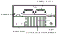
d) The microneedle array production mould containing the stock solution/suspension of the active cargo in the needle cavity was spin dried at 3500rpm and the desired temperature for 30 minutes, with a continuous flow of purge gas through the centrifuge at a rate of 0-50l/min to help concentrate the dried active cargo at the needle tip. The purge gas may be introduced into the chamber through a tubular inlet. The water content can be reduced using a dryer adjusted to the desired temperature and recycled to the centrifuge chamber. The purge gas may be air, nitrogen, carbon dioxide, or another inert or reactive gas as desired for a particular cargo. The flow rate is measured by a flow meter and controlled by a circulation pump device.
e) Can be measured per cm2Microneedle array production mold area 100 μ l of a 20% CMC90 hydrogel aqueous solution was added to the microneedle array production mold surface to load the structural components of the microneedle array device.
f) The microneedle array production mold can be centrifuged at 4500rpm and at the desired temperature for 10 minutes without purging gas exchange in the centrifuge chamber to fill the needle cavity of the microneedle array production mold with the CMC90 hydrogel. This may be followed by incubation for 30 minutes to allow rehydration of the active cargo previously deposited on the microneedle array tips.
g) The microneedle array production mold was centrifuged at 3500rpm and the desired temperature for 3 hours or more and a constant flow of purge gas of 0 to 50l/min was passed through the centrifuge chamber to spin dry the MNA device to a moisture content of less than 5%.
h) The dried microneedle array device can then be separated from the microneedle array production mold and stored under desired conditions. In some embodiments, CMC 90-based devices may be stored between about 50 ℃ to-86 ℃.
Examples of manufactured microneedle arrays carrying a tip-loaded active cargo may be shown in fig. 3A through 6B.
Micromilled master molds and rotationally molded microneedle arrays
In the following embodiments, a micro-milling step may be performed to manufacture microneedle arrays of various gauges. It should be understood, however, that the following embodiments describe certain details of microneedle array fabrication that are applicable to methods of microneedle array fabrication that do not include a micro-milling step, including the methods described above in the previous examples.
In the following embodiments, an apparatus and method for manufacturing a soluble microneedle array is described that uses a master mold formed by a micro-milling technique. For example, microneedle arrays can be manufactured based on a master (positive) to production mold (negative) to array (positive) approach. In fact, micro-milling techniques can be used to create various micro-geometries on any type of material, including metal, polymer, and ceramic parts. Micro-milled master molds of various shapes and configurations can be effectively used to create multiple identical concave production molds. The concave production mold can then be used to micro-cast various microneedle arrays.
Fig. 7 illustrates an example of a precision-micromilling system that can be used to fabricate a microneedle master. Mechanical micro-milling uses a microscopic (e.g., as small as 10 μm) milling tool located within a micro-machine platform that is precisely controlled by a computer. The system may include a microscope to view the surface of the workpiece being cut by the microtool. The microtool may be rotated at ultra-high speeds (200,000rpm) to cut the workpiece to produce the desired shape. As described above, micro-milling methods can be used to create complex geometric features on a variety of materials. In the micro-milling process, various types of tools may be used, including, for example, carbide micro tools. However, in a preferred embodiment, a diamond tool can be used to fabricate an array of microneedles on a master mold. A diamond tool may be preferred over other types of tools because it is harder than conventional materials (e.g., carbide) and may provide cleaner cuts on the surface of the workpiece.
The master mold can be micro-milled from a variety of materials, including, for example, the master mold materials described in exemplary embodiments (DuPont,
 Polyimide). The master mold can be used to produce materials from suitable materials, such as those described in the exemplary embodiments below
 184(Dow Corning) — a flexible production mold was made. The master mold is desirably formed of a reusable material so that a single master mold can be reused to make a large number of production molds. Similarly, each production mold is ideally capable of manufacturing a variety of microneedle arrays.
The master mold can be produced relatively quickly using micro-milling techniques. For example, a master mold comprising a 10mm x10 mm array of 100 microneedles can take only less than two hours to micro-mill, in some embodiments, less than about 30 minutes. Thus, the short waiting time enables rapid manufacturing of different geometries, which allows rapid development of microneedle arrays and also facilitates experimentation and study of various microneedle parameters.
Preferably, the master mold material is capable of being removed from the production moldCleanly separated in the material and preferably capable of withstanding any high curing temperatures that may be necessary to cure the production mold material. For example, in one illustrative embodiment, the silicone-based compound 184(Dow Corning) is the production mold material, which typically requires a cure temperature of about 80 to 90 degrees celsius.
The master model can be created in various sizes. For example, in one exemplary embodiment, the master mold is 1.8mm thick (DuPont,
 Polyimide) and 5.0mm thick acrylic plates (sheets). The plates may first be flattened by a micro-milling tool and the locations where the microneedles are to be created may be raised from the rest of the surface. The microtool may be used in conjunction with a digitally controlled micro-milling machine (fig. 1) to create microneedle features (e.g., as defined by a master mold). In this way, the micro-milling process can fully control the size, sharpness, and spatial distribution of the microneedles.
FIG. 8 is an image from a Scanning Electron Microscope (SEM) showing the structure of a micro-milled master mold having a plurality of pyramidal needles. As shown in fig. 8, a circular groove can be formed around the microneedle array of the master mold to create an annular (e.g., circular) wall portion in the production mold. The circular wall section in the production mold may assist in the rotational casting process discussed below. Although the wall portions shown in FIG. 9 and each of the female mold structures shown in FIG. 8 are circular, it should be understood that other geometric wall portions or containment vessels may be provided. For example, the containment vessel may be formed in various shapes, including, for example, square, rectangular, trapezoidal, polygonal, or various irregular shapes, depending on the desired shape of the microneedle array device.
As discussed above, can be prepared from 184(Dow Corning) preparation of production molds, said
 184 is a two-part fully curable silicone elastomer, and may be
 Mixed with the curing agent in a ratio of 10: 1. The mixture was degassed for about 10 minutes and poured onto a master mold to form a layer of about 8mm, after which it was degassed again for about 30 minutes and cured at 85 ℃ for 45 minutes. After cooling to room temperature, the master mold can be separated from the cured silicone and the silicone production mold trimmed the edges of the circular wall sections surrounding the array (fig. 9). A large number of production molds (e.g., 100 or more) can be made from a single master mold, with
 Or very little, if any, visible degradation of the acrylic master mold.
Fig. 9 is an SEM image of the cone-shaped production mold created as described above. Fig. 10 shows in the center of the image an enlarged portion of a production mold with a cone-shaped needle molding well. The mold well is configured to receive a base material (and any ingredients added to the base material) to form microneedles having an external shape defined by the mold well.
To construct the microneedle array, a base material may be used to form the portions of the individual microneedles that contain the bioactive component as well as the portions that do not contain the bioactive component. As discussed above, each microneedle may contain the bioactive component only in the microneedle, or in some embodiments, only in the top half of the microneedle, or in other embodiments, only in the portion of the microneedle that tapers near the tip. Therefore, in order to control the delivery of the bioactive ingredient and to control the cost of the microneedle array, each microneedle preferably has a portion containing the bioactive ingredient and a portion containing no bioactive ingredient. In embodiments described herein, the portion free of bioactive components comprises the support structure of the microneedle array, and in some embodiments, a base portion (e.g., the bottom half) of each microneedle in the array.
Various materials can be used as the base material of the microneedle array. The structural substrate of biodegradable solid microneedles most commonly includes poly (lactic-co-glycolic acid) (PLGA) or carboxymethylcellulose (CMC) based formulations; however, other base materials may be used.
CMC is generally preferred over PLGA as the base material for microneedle arrays described herein. PLGA-based devices may limit drug delivery and vaccine administration due to the relatively high temperatures (e.g., 135 degrees celsius or more) and vacuum required for manufacturing. In contrast, CMC-based matrices can be formed at room temperature in a simple rotational casting and drying process, making CMC-microneedle arrays more desirable for incorporation into sensitive biologicals, peptides, proteins, nucleic acids, and other various bioactive components.
Can be used in sterile dH2O, CMC-hydrogel was prepared from CMC low viscosity sodium salt with or without active ingredient (as described below). In exemplary embodiments, CMC may be mixed with sterile distilled water (dH)2O) and active ingredient to achieve a CMC concentration of about 25 wt%. The resulting mixture can be stirred well and equilibrated at about 4 degrees celsius for 24 hours. During this time, the CMC and any other components may be hydrated and form a hydrogel. The hydrogel may be vacuum degassed for about 1 hour and centrifuged at about 20,000g for 1 hour to remove residual micro-scale bubbles, which may interfere with the rotational casting/drying process of the CMC-microneedle array. The dry matter content of a portion (10g) of the hydrogel can be tested by drying it at 85 degrees celsius for about 72 hours. The ready-to-use CMC-hydrogel is ideally stored at about 4 degrees celsius prior to use.
The active ingredient may be incorporated into the CMC hydrogel prior to the rotational casting process at a relatively high (20-30%) CMC-to-dry biologics weight ratio. The arrays can be spin cast at room temperature to make the process compatible with the functional stability of a structurally wide range of biologically active ingredients. Since the master mold and the production mold can be reused for a large number of manufacturing cycles, the manufacturing cost can be greatly reduced. The resulting dehydrated CMC-microneedle arrays are generally stable at room temperature or slightly lower temperatures (e.g., about 4 degrees celsius), and can retain the activity of the incorporated biologicals, facilitating simple, low-cost storage and dispensing.
In an exemplary embodiment, the surface of the production mold may be covered with about 50. mu.l (for a mold with a diameter of 11 mm) of CMC-hydrogel and spin cast by centrifugation at 2,500g for about 5 minutes. After the initial CMC-hydrogel layer, an additional 50. mu.l of CMC-hydrogel may be layered on the mold and centrifuged at 2,500g for about 4 hours. At the end of the drying process, the CMC-microneedle array may be separated from the mold, trimmed of excess material on the edges, collected and stored at about 4 degrees celsius. The production mold may be cleaned and reused in other casting of microneedle arrays.
In some embodiments, the CMC-solid may be formed with an active-free layer and an active-containing layer. Fig. 11A-D illustrate CMC-solids of different shapes (fig. 11A and 11B) and embedding the active cargo in the upper layer, which becomes the microneedle portion containing the active ingredient after micro-milling. Fig. 11C illustrates a micrometer-sized fluorescent particle layered on the surface of the inactive ingredient-containing layer, and fig. 11D illustrates an example of toluidine blue layered on the surface of the inactive ingredient-containing layer.
Fig. 12A and 12B also illustrate different shapes of CMC-solids, with fig. 12B showing a square and fig. 12B showing a rectangle. Both CMC solids may be milled to size for further processing as described herein. It is to be understood that the geometries and reactive cargo shown herein are not intended to be limited to the exemplary embodiments.
Example 2
CMC-solids can be prepared with defined geometries and active cargo content in one or more layers of the prepared structure. Examples of active cargo integrated into CMC-solids are described in more detail herein. In constructing a CMC-solid comprising an embedded active cargo in at least one layer of the CMC-solid, the CMC-solid can be milled to an engineering specific dimension and micro-milled to fabricate the microneedle devices described herein.
Example 3
In another embodiment, one or more layers of active cargo may be embedded in the CMC-solid to directly micro-mill the microneedle array. Fig. 13 illustrates a sample representation of vertical multi-layer deposition and CMC embedding of a reactive cargo on a CMC-solid for direct micromilling of MNA devices.
In one exemplary method, microneedle arrays can be fabricated by preparing CMC-solids having a defined geometry without any active cargo therein. Thereafter, the blank CMC-solid may be milled to the desired dimensions.
As shown in fig. 13, to contain the active cargo, particularly in the tip of a micro-milled MNA device, the active cargo may be deposited on the CMC-solid in an engineering specific geometric pattern.
Methods of depositing the active cargo onto the blank CMC-solid may include, for example:
1) direct printing was performed using micro-nozzle assisted droplet deposition.
2) Transfer from preprinted substrate.
3) Droplet deposition was performed using a computer controlled robotic system.
FIG. 14 illustrates the layering and spatial distribution of the active cargo embedded in the CMC-solid block. After the first layer deposition (a), it may be covered (B) with a CMC layer that provides a surface for subsequent reactive cargo (C) deposition. This process can be repeated until all desired layers have been deposited and encapsulated in a solid CMC-block suitable for the micro-milling process (D-F).
Fig. 15 illustrates a schematic cross-sectional view of a CMC-block (a) encapsulating a deposit of active cargo in a spatially controlled manner. The method allows three-dimensional control and placement of the active ingredient after MNA-device micro-milling (B). In panel (B) of fig. 15, the layout of the reactive cargo is shown in the trunk of the reactive cargo; however, by controlling the milling process, the layout can be controlled in the vertical direction from the tips of the microneedles to the substrate. Each color represents a different active ingredient or different amount/concentration of the same material.
Thus, a method of vertical laminate deposition of active cargo in microneedles is provided by continuously depositing one or more active cargos in contact with each other or separated by a CMC layer on a CMC-solid surface. In some embodiments, horizontal deposition of the active cargo may result in spatial separation of the cargo. By combining the vertical and horizontal modes of active cargo deposition, three-dimensional delivery and distribution of each defined active ingredient can be achieved, thereby reducing the waste of active ingredients during the manufacture of microneedle arrays.
Microneedle-integrated adenovirus vectors
The following embodiments are directed to soluble microneedle arrays, such as those described herein, incorporating infectious viral vectors into the soluble matrix of the microneedle array. Using this technique, live viral vectors can be incorporated into microneedle arrays for the first time. As described herein, incorporation of viral vectors into the disclosed microneedle arrays can stabilize viral vectors such that they retain their infectivity after incorporation and after extended storage times. Application of adenoviral vectors (MIAs) incorporated into microneedle arrays to the skin results in transfection of skin cells. In the context of vaccines, we have demonstrated that dermal administration of MIAs encoding HIV antigens results in an effective HIV-specific immune response. These results are described in more detail in the examples below.
Example 4
The methods of preparing adenoviral vectors integrated into microneedles described herein maintain the viability of the adenoviral particles during preparation and dry storage. These steps were specifically designed based on the physical and chemical properties of the CMC microneedle array. The virus viability in the CMC microneedle array was achieved by the following steps:
-comprises a low viscosity carboxymethylcellulose (CMC90) with a final concentration of 2.5% (step 2), and
concentrating the adenovirus particles in the microneedle array device tips by timed and temperature controlled spin drying (step 6).
Controlled partial rehydration of the adenovirus particles loaded by the needle tip (step 8).
Preparation of adenoviral vectors (MIAs) integrated into tip-loaded microneedles:
1) adenovirus particles were dosed at 2x10⁹The particles/ml were resuspended at density in trehalose storage buffer (5% trehalose Sigma-Aldrich USA, 20mM Tris, pH 7.8, 75mM NaCl, 2mM MgCl20.025% Tween 80)
2) The resuspended virus stock was mixed with an equal volume of 5% CMC90 in trehalose storage buffer to give a density of 1X10⁹Particle/ml adenovirus working stock.
3) At 40. mu.l/cm2Amount of surface area an adenovirus working stock suspension was added to the surface of the microneedle array production mold (as described in detail in other embodiments herein).
4) The mold was centrifuged at 4500rpm and 22 ℃ for 10 minutes to fill the tip with adenovirus working stock.
5) Excess virus stock was removed and used per cm2The mold surface was washed with 100. mu.l of Phosphate Buffered Saline (PBS) solution.
6) Microneedle array molds containing only adenovirus stock in the needle cavity were spin dried locally at 3500rpm and 22 ℃ for 10 minutes.
7) In per cm 2100 μ l of a 20% structurally cargo-free CMC90 hydrogel in water was added to the microneedle array mold surface to form the structure of the MIA device.
8) The needle lumen was filled with 20% CMC90 by centrifugation at 4500rpm and 22 ℃ for 10 minutes and incubated for 30 minutes to rehydrate the dried adenovirus particles in the tip (steps 3 to 6 above).
9) The MIA apparatus was spin-dried by centrifugation to a water content of less than 5%, under conditions of 3500rpm and 22 ℃ for 3 hours and a constant gas flow of 10l/min through the centrifuge chamber.
10) The dried MIA devices were demolded and stored at 4 ℃ or-80 ℃.
Example 5
We have evaluated the potency and stability of recombinant adenovirus particles incorporating MNAs. Ad5.EGFP incorporation into CMCHydrogel MNAs to produce a final product containing 1010 virus particles/MNA. Control blank MNA without virus was prepared similarly. Batches of Ad5.EGFP and control MNA were stored at room temperature, 4 ℃ and-86 ℃ and evaluated for virus stability in infectivity assays. The specific transduction activity of the MNA-incorporating ad5.egfp virus was evaluated in vitro using 293T cells. Cells were plated at 2X10⁶Perwell were placed in six-well plates and transduced in duplicate with diluted viral suspensions, suspensions + blank MNA (control) or Ad5.EGFP MNA stored at room temperature, 4 ℃ and-86 ℃ for the indicated time periods. As a negative control, untransduced wells were included. After 24 hours, the original cell population was analyzed by flow cytometry for GFP expression (representative histograms are shown in fig. 35).
As shown in fig. 35, inclusion of ad5.egfp into MNA did not reduce transduction efficiency. Flow cytometric analysis of GFP expression 24 hours after transfection of target 293T cells with the same titers of ad5.egfp taken from suspension or incorporated into CMC-patches (patches) compared to untransfected control cells. Figure 36 shows the stability of MNA-embedded ad5.egfp virus. GFP gene expression was analyzed by flow cytometry, as in fig. 37, and normalized to the infection efficiency of ad5.egfp suspensions stored at-86 ℃.
It was found that the infection efficiency with MNA Ad5.EGFP virus was 87.92 ± 4.5%, which is similar to that observed for Ad5.EGFP suspensions stored at conventional-86 ℃ (fig. 35 and 36), indicating that the preparation method did not adversely affect the transduction efficiency of Ad-EGFP virus particles. To evaluate infectivity changes over time, transfection efficiencies of freshly prepared ad5.egfp suspensions stored at-86 ℃ were compared to MNA-containing ad5.egfp stored at room temperature, 4 ℃ or-86 ℃ for extended periods of time. Infectivity was reported for storage periods up to 365 days (normalized to ad5.egfp suspension + blank CMC-patch) (fig. 36). These results indicate that the infectivity of MNA ad5.egfp stored at 4 ℃ or-86 ℃ is very stable, slightly stable up to 30 days at room temperature.
These results demonstrate that the Ad transgene delivered by the microneedle array is expressed in the skin and elicits an effective cellular immune response. To specifically assess gene expression in vivo, we determined GFP expression in the skin following either traditional intradermal injection (i.d.) or microneedle array-mediated intradermal delivery. We delivered by ID injection or administered locally via a single microneedle array 108ad5.gfp viral particles (fig. 37). Skin was collected after 48 hours, frozen sections thereof and counterstained with blue fluorescent DAPI to identify nuclei, followed by imaging by fluorescence microscopy. Significant cellular GFP expression was observed after both i.d. and microneedle array delivery. To assess immunogenicity, we assessed in vivo antigen-specific lytic activity without enhancement after single i.d. or microneedle array immunization. To this end, we immunized groups of mice with an Ad 5-based vector deleted of E1/E3 encoding either the full length of codon-optimized SIVmac239 gag or SIVmac239 gag p17 antigen (Ad5.siv gag, Ad5.siv gag p 17). Blank vector was used as control (Ad 5). We observed an effective and similar level of in vivo lytic activity specific to dominant SIVgag p 17-derived peptide KSLYNTVCV (SIVmac239 gag 76-84) after i.d. or microneedle arrays immunisation with either ad5.siv gag or ad5.siv gag p17 (fig. 37, CTL).
The microneedle array technology disclosed herein may also be useful for clinical gene therapy. It addresses at least two major limitations of, for example, conventional approaches. First, it enables long-term stabilization and storage of recombinant viral vectors. By making live viral vectors that have been demonstrated to be equivalent to frozen liquid formulation serum resistant to high and low temperatures, the stability of the microneedle array will alleviate the stress associated with the "cold chain". Furthermore, integration into microneedle arrays enables accurate, consistent and reproducible dosing of viral vectors that is not achievable by conventional methods. Finally, the viral vector is repackaged in the only necessary delivery device (i.e., a biocompatible and completely disposable microneedle array that directs delivery precisely to the superficial layers of the skin).
Such gene delivery platforms are useful in providing patient-friendly clinical gene therapy. Since these microneedle arrays have been designed not to penetrate to the depth of blood vessels or neural structures, gene delivery to human skin will be painless and non-bleeding. Furthermore, the manufacturing process is flexible, enables simple and fast low cost manufacturing, and has efficient scale-up potential. Also, as an end product, the MIA device is stable at room temperature and is inexpensive to transport and store. Taken together, these structural and manufacturing advantages may enable broad and rapid clinical deployment, making such gene delivery technologies readily applicable for the prevention and/or treatment of a wide range of human diseases. Furthermore, this approach can be extended to other vector-based vaccine platforms (e.g., vaccinia virus, AAV, etc.) that are currently limited by the same limitations. For at least these reasons, the disclosed microneedle arrays and methods of use thereof have significantly driven the development of the field of recombinant gene therapy.
Microneedle array-exemplary active ingredients
The various active ingredients will be described in detail below. For convenience, the following examples are based on a 6.3x 6.3mm microneedle array. This size and thus cargo delivery can be varied by increasing or decreasing by 2 to 100 times.
Typical considerations for maximum active cargo quantity include, for example, the total needle volume in the array and the solubility of the active ingredient(s) in the solvent (typically expected to be < 50%).


Tip loading of live adenoviruses typically involves the following modifications:
a) there was 5% trehalose and 2.5% CMC90 in the tip-loaded hydrogel suspension.
b) The process temperature was maintained at 22 ℃.
In addition, lentiviral (Lenti viral) vectors typically require treatment at 4 ℃ and humidity control based on a vapor trap (vapor trap). Likewise, short epitope peptides are typically dissolved in DMSO and the solvent evaporation time during tip loading is 4 hours.
Microneedle structures and shapes
For each of the embodiments below, it is to be understood that one or more layers of active ingredient may be provided in the microneedles of the microneedle array as described above. Thus, for example, in some embodiments, the active ingredient may be provided only within the microneedle region, and not in the structural support of the array, as shown in fig. 15. Furthermore, in other embodiments, the active ingredient is concentrated in the upper half of the microneedle, such as the tip of the microneedle shown in fig. 3A-4B.
Fig. 16A and 16B are SEM images of CMC-microneedle arrays formed from a plurality of pyramidal projections (e.g., microneedles). The average tip diameter of the pyramidal needle shown in FIG. 16A is about 5 to 10 μm. As shown in fig. 16B, the sides of the pyramidal needle can form curved and/or arcuate faces that can facilitate insertion into the skin.
Fig. 17 is another SEM image of a single needle in a microneedle array. The microneedles shown in fig. 17 are base-extended pillar-molded CMC-microneedles. The base-extended columnar microneedles include a base portion that is generally polygonal (e.g., rectangular) in cross-section and a protruding portion extending from the base portion. The projection has a substantially rectangular lower portion and a tip portion that generally tapers to a point. The tip portion is generally cone-shaped, and the exposed face of the cone-shape may be flat or arcuate. The projection may be half or more of the entire length of the needle.
Fig. 18 and 19 illustrate micrographs of CMC-microneedles molded in pyramidal shapes (fig. 18) and columnar shapes (fig. 19). Because the cone-shaped needle has a cross-section (size) that continuously increases from the point of the needle tip to the base of the needle, the force required to continue to push the cone-shaped needle into the skin as the needle enters the skin also increases. In contrast, the cylindrical needle, once it reaches the generally rectangular portion of the protruding portion, has a generally continuous cross-sectional profile (dimension). Thus, cylindrical needles may be preferred over conical needles because they may allow the needle to be introduced into the skin with less force.
Fig. 20 illustrates a schematic of the shape and structure of microneedles that are generally suitable for fabrication by rotational casting of materials into a master mold formed via micro-milling. Since the shapes and structures shown in fig. 20 do not contain any undercuts, they do not generally interfere with the molding/demolding process. The structure in fig. 20 includes (a) generally pyramidal microneedles, (b) "sharp" columnar microneedles (without the base component in fig. 8), (c) "wide" columnar microneedles, (d) "short" columnar microneedles (with short columnar portions and longer punctate portions), and (e) "rounded columnar microneedles.
While pyramidal microneedles may have a larger volume than cylindrical microneedles, their increased cross-sectional profile (size) requires increased insertion force. Thus, the geometry of the pyramidal microneedles can result in reduced insertion depths and reduced effective delivery volumes. On the other hand, a smaller cross-sectional area and a larger aspect ratio of the pillar-shaped microneedles may result in a lower destructive force limit. The smaller the apex angle α, the more "sharp" the microneedle tip. However, if the apex angle is too small (e.g., below about 30 degrees), the resulting microneedle volume and mechanical strength can be reduced to undesirable levels.
The penetration force of a microneedle is inversely proportional to the sharpness of the microneedle, which is characterized not only by the angle of the microneedle (apex angle) but also by the radius of the microneedle tip. The sharpness of the tip also depends on the reliability of the mold when the apex angle is defined by the geometry of the master mold. The micro-milling of the master mold described herein results in increased accuracy in the geometry of the mold, which in turn results in increased accuracy and reliability in the resulting production mold and microneedle array formed therefrom.
The increased accuracy of micro-milling allows for more precise and detailed components to be included in the mold design. For example, as discussed below in the next section, forming rounded corners at a pillar-shaped microneedle substrate can significantly increase the structural integrity of the microneedles, which reduces the likelihood of failure or breakage of the microneedles upon impact with the skin. While these rounded corners can significantly increase the strength of the microneedles, they do not interfere with the functional requirements of the microneedles (e.g., penetration depth and biological volume). The rounded corners are very small features that can be difficult to create in a master mold formed by conventional methods. However, the micro-milling techniques described above allow for the inclusion of such small features with little or no difficulty.
Mechanical integrity and penetration capability
Microneedle arrays are preferably configured to penetrate the stratum corneum to deliver their cargo (e.g., biologicals or bioactive ingredients) to the epidermis and/or dermis while minimizing pain and bleeding by preventing their penetration to deeper layers, which may include nerve endings and blood vessels. To evaluate the mechanical feasibility of the manufactured microneedle arrays, tests were performed on pyramidal and columnar microneedle arrays as representative variations of the array geometry (e.g., shown in fig. 8). The first set of experiments, which illustrate the failure limits of the microneedles, involved pressing the microneedle array against a solid acrylic surface at a constant contact speed while measuring the force and displacement until failure occurs. The second set of experiments demonstrated the ability of the microneedles to pierce on human skin explants.
FIG. 21 illustrates a test rig designed for functional testing. The sample (i.e., microneedle array) was mounted on a fixture, which was moved at a constant speed of about 10mm/s towards a fixed acrylic artifact using a computer controlled moving platform (ES14283-52 Aerotech, Inc.). Three-dimensional force meters (9256C1, Kistler, Inc.) containing acrylic artifacts enable highly sensitive measurement of forces.
Fig. 22 illustrates a force-displacement curve of data measured during a failure test. The left curve represents data obtained from the columnar microneedle sample tested, and the right curve represents data obtained from the pyramidal microneedle sample tested. As seen in fig. 22, the destruction of these two types of microneedles is significantly different; the pyramid-like array is plastically deformed (bent), and the columnar array shows breakage of the columns at the base thereof. This different failure behavior gives it significantly different displacement-force data. The failure (breakage) event can be easily identified from the displacement-force data shown in the figures. Based on the obtained data, it was found that the breakage points of the columnar microneedles were 100mN on average. Since only about 40mN of force is required to penetrate the stratum corneum, the microneedles are strong enough to penetrate human skin without being damaged. Furthermore, since parallelism between the microneedle tips and the acrylic artifacts cannot be fully established, the practical damage limit is likely to be significantly higher than 100mN (i.e. the microneedles are damaged in a continuous manner, rather than breaking most/all of them at the same time).
Pyramidal microneedles show a sustained increase in force characteristic without evidence of a distinct failure point. To identify the failure limit of pyramidal microneedles, a discontinuous test was performed in which a certain number of microneedles were pushed towards the artifact, retracted, and examined by optical micrographs. This process was continued until failure was observed. For this reason, the destruction is defined as the pyramidal microneedle bending more than 15 degrees.
To further analyze the destruction of the microneedles, a Finite Element Model (FEM) of the microneedle array was developed as shown in fig. 23. To obtain the mechanical properties (elastic modulus and strength limit) of the CMC material, a series of nanoindentation tests (using a Hysitron nanoindenter) were performed. The mean modulus of elasticity and yield strength of the CMC material (as prepared) were 10.8GPa and 173MPa, respectively. This indicates that the CMC material prepared has a higher elastic modulus and yield strength than both PMMA (elastic modulus: 3.1GPa, yield strength: 103MPa) and polycarbonate (elastic modulus: 2.2GPa, yield strength: 75MPa), indicating that the CMC material has superior strength and hardness compared to other polymers.
Using this data, a series of FEM simulations were performed. It is predicted from the FEM model that for asymmetric loading (5 degree misload orientation), the destruction limits of the microneedles are 400mN (cone shape) and 290mN (sharp column shape) for cone and sharp column (width 134 μm) microneedles with a height of 600 μm, an apex angle of 30 degrees, and a fillet radius of 20 μm. Considering a minimum penetration force requirement of about 40mN, pyramidal and sharp columnar microneedles will have a safety factor of about 10 and 7.25, respectively.
The columnar breaking load increased to 350mN when the fillet radius doubled to 40 μm, and decreased to 160mN when the fillet radius decreased to 5 μm, which was close to the experimentally determined breaking load. The height and width of the posts have a significant effect on the breaking load. For example, for a column with a width of 100 μm, an increase in height from 500 μm to 1000 μm reduces the breaking load from 230mN to 150 mN. When the width was reduced to 75 μm, the breaking load was shown to be 87mN for a column height of 750 μm.
To evaluate penetration, pyramidal and sharp columnar microneedle arrays were tested for their ability to penetrate water-based model elastomeric substrates and full thickness human skin. Fig. 24 illustrates a stereomicrograph of pyramidal microneedle arrays (panels A, C and E) and columnar microneedle arrays (B, D and F) after exposure to a model elastomer for 4 minutes. In particular, after application of the pyramidal or columnar microneedle arrays, toluene blue tracer dye was deposited on either model elastomeric substrates (panels C and D) or fresh ex vivo full thickness human skin explants (panels E and F).
The model elastomeric substrate includes about 10% CMC and about 10% pigskin gelatin in PBS gelled at about 4 degrees celsius for about 24 hours or more. The elastomer surface was covered with a sealing film (parafilm) of about 100 μm thickness to prevent direct contact of the needle tip and patch material with the water-based model elastomer. To enable stereo microscopy imaging, trypan blue tracer dye (Sigma chem., cat # T6146) was incorporated into the CMC-hydrogel at a concentration of 0.1%. The patch was applied using a spring-loaded applicator and analyzed after about 4 minutes of exposure. Based on physical observation of the dye in the target substrate, the dissolution of two different geometries of microneedles is significantly different.
A sharp cylindrical needle applied to the model elastomeric substrate released substantially more tracer dye into the gel matrix than was observed with the cone-like design (fig. 24, C vs. d). The image of the recovered patch (fig. 24, a vs. b) is consistent with this observation, as the degradation of the sharp cylindrical needles is more advanced than the degradation of the pyramidal needles. To extrapolate this analysis to a more clinically relevant model, pyramidal and columnar microneedle arrays were applied to fresh ex vivo full thickness human skin explants using the same force as from a spring loaded applicator. Consistent with the results of the elastomer model, the pyramidal microneedle array deposited significantly less tracer dye than the sharp columnar microneedle array (fig. 24, E vs.
To further evaluate the penetration and delivery effectiveness to human skin, CMC-microneedle arrays were fabricated using BioMag (Polysciences, inc., cat # 84100) beads or fluorescent particulate tracers (fluoroesbrite YG 1 μm, Polysciences inc., cat # 15702). As previously described, pyramidal CMC-microneedle arrays containing fluorescent or solid microparticles were applied to living human skin explants. At 5 minutes post-application, surface residues were removed and skin samples were cryosectioned, then counterstained with toluene blue and imaged by light microscopy (fig. 25A and 25B) or fluorescence microscopy (fig. 25C).
Pyramidal CMC-microneedles effectively penetrate the stratum corneum, epidermis and dermis of living human skin explants as evidenced by the deposition of Biomag beads arrayed along the penetration lumen corresponding to each needle insertion point (typical sections are shown in fig. 25A and 25B). In particular, the deposition of ordered cavities (fig. 25A, cavities numbered 1 to 4, toluene blue contrast stain, 10x) and Biomag particles (brown) arranged along the penetrating cavities was evident (fig. 25B, 40x), indicating that the microneedles penetrated human skin. In addition, analysis of sections of live human explants stained with DAPI for nuclear identification and MHC II identification+anti-HLA-DR assays performed by antigen-presenting cells show high density of fluorescent microparticles deposited in the superficial epidermis and dermis, including II+Co-localized particles of antigen-presenting cells (FIG. 25C, DAPI (blue), HLA-DR)+(red) and fluorescent particles (green), 40 ×).
These results also demonstrate that the CMC microneedle arrays described herein can effectively penetrate human skin and deliver intact drugs (bioactive ingredients), including insoluble microparticles. They are consistent with efficient delivery of particulate antigens to antigen presenting cells in human skin, a major goal of current rational vaccine design.
To further illustrate the in vivo delivery of microneedle arrays, the dorsal otic surface of anesthetized mice was similarly administered an array containing fluorescent particlesBut mimics the dermal delivery of particulate antigen in vivo. After 5 minutes, the patch was removed and the mice recovered normal activity. At 3 hours or 3 days, the ear skin and draining lymph nodes were analyzed for the presence of fluorescent particles. Consistent with the observation on human skin, there were significant microparticles in the ex vivo skin from the array application site (data not shown). In addition, at the 3 day time point, there was a significant number of particles in the draining lymph nodes. FIGS. 26A and 26B illustrate that there are a significant number of particles in the draining lymph node (FIGS. 26A, 10X), including those associated with II+Cell-like, closely associated particle clusters (fig. 26B, 60x), indicating the presence of antigen presenting cells containing internalized particles within the lymph nodes.
To quantitatively evaluate the effect of needle geometry on cargo delivery using microneedle arrays, constructed3An H-tracer labelled CMC-microneedle array. CMC-hydrogels with a final dry weight content of 25 wt% (5g/95g OVA/CMC) were formulated using 5 wt% ovalbumin as model active ingredient, and 0.1 wt% trypan blue and 0.5x10⁶dpm/mg dry weight3H-tracer (to)3Form of H-thymine) (ICN Inc., cat #2406005) was tracer-labeled. Four batches were made from a single batch of labeled CMC-hydrogel formulation3H-CMC-microneedle arrays comprising several separate batches of pyramidal and sharp cylindrical needle geometries. The patch was applied to human skin explants as described above and the patch was removed after 30 minutes of exposure. The patch treated area was stripped with tape to remove surface debris and cut using a 10mm biopsy punch. Determination in vitro of human skin explants by scintillation counting3The H content. Measure and determine3The specific activity of the H-CMC-microneedle patch-material was calculated as 72,372cpm/mg dry weight. This specific activity was used to indirectly determine the amount of ovalbumin delivered and retained in the skin. The data obtained are summarized in table 1 below.
The patch types tested were consistent between different microneedle arrays (mean standard deviation 24 to 35%) and between different lots (mean standard deviation 7 to 19%). The intra-batch variability of the geometry of the two needles was less than the inter-batch value, indicating that the insertion process and the target were characterizedA major role may play in successful transdermal material delivery and retention. The retained data of the patch material clearly demonstrates that the microneedle geometry is most important in transdermal cargo delivery. The geometry of the cylindrical needle provides a 3.89 times greater overall diameter than a conical needle3H deposition of the marked needle material. Based on the deposited radioactive material, it is estimated that pyramidal needles are inserted about 200 μm deep, while cylindrical needles are inserted about 400 μm or more.
TABLE 4.2.5 by conical and cylindrical needles3Transfer of H-labeled CMC-microneedle materials to human skin explants

Ideally, microneedle arrays as described herein can be used for skin immunization. The development of strategies for the efficient delivery of antigens and adjuvants is a major goal of vaccine design, and immunization strategies targeting cutaneous dendritic cells have several advantages over traditional vaccines.
The microneedle arrays described herein are also effective in chemotherapy and immunochemistry applications. The efficient and specific delivery of chemotherapeutic agents to tumors, including skin tumors, is a major goal of modern tumor therapy. However, systemic delivery of chemotherapeutic agents is limited by a variety of well-established toxicities. In the case of skin tumors, including tumors of skin origin (e.g., basal cells, squamous cells, merkel cells and melanoma) and tumors of metastasis to the skin (e.g., breast cancer, melanoma), local delivery may be effective. Existing methods of topical delivery typically require the application of creams or repeated topical injections. The effectiveness of these methods is currently limited by limited penetration of the active agent into the skin, non-specificity, and unwanted side effects.
Microneedle arrays of the present disclosure may be used as an alternative or supplement to traditional topical chemotherapy. The microneedle arrays of the present disclosure can penetrate the outer layer of the skin and effectively deliver active biologies to the living cells of the dermis and epidermis. Delivery of chemotherapeutic agents results in apoptosis and death of skin cells.
In addition, multiple bioactive agents can be delivered in a single microneedle array (patch). This enables immunochemical therapy based on the co-delivery of cytotoxic agents and immunostimulating agents (adjuvants). In the immunogenic environment created by the adjuvant, the tumor antigens released from dying tumor cells will be presented to the immune system, thereby inducing a local and systemic anti-tumor immune response capable of suppressing tumor cells at the site of treatment and throughout the body.
In one exemplary embodiment, the delivery of biologically active small molecules is investigated. In particular, chemotherapeutic agents delivered to the skin using CMC microneedle arrays were investigated Activity of (2). Use of
 So that biological activity can be measured directly using a representative of a class of agents (
 Inducing cell death in the skin), which agents have potential clinical utility for the topical treatment of a range of skin malignancies.
To directly assess the immunogenicity of antigens incorporated into CMC microneedle arrays, well characterized model antigen ovalbumin was used. Pyramidal arrays incorporating either soluble ovalbumin (sOVA) or microsomal ovalbumin (pOVA), or arrays containing both pOVA and CpGs, were made. The adjuvant effects of CpGs have been well characterized in animal models and their adjuvant activity in humans is currently being evaluated in clinical trials.
Immunization was achieved by applying an antigen-containing CMC-microneedle array to the ear of an anesthetized mouse using a spring-loaded applicator as described above, and removing the array 5 minutes after application. These pyramidal microneedle arrays contained about 5 wt.% OVA in CMC and about 0.075 wt.% (20 μ M) CpG. As a positive control, a gene gun based gene immunization strategy was used, which utilized plasmid DNA encoding OVA. For the induction of CTL-mediated immune responses in mouse models, gene gun immunization is one of the most efficient and reproducible methods, suggesting its use as a "gold standard" for comparison of these experiments.
Mice were immunized, boosted one week later, and then analyzed for OVA-specific CTL activity in vivo. Remarkably, immunization with arrays containing low amounts of OVA and CpG induced high levels of CTL activity, similar to those observed by gene gun immunization (fig. 27). Both OVA antigens delivered with microparticles and soluble arrays induced significant OVA-specific CTL activity even in the absence of adjuvant. It has been demonstrated that similar responses require substantially higher doses of antigen when delivered by conventional needle injection.
To evaluate the stability of the arrays produced, different batches of arrays were produced and stored, and then used over a long period of time. As shown in fig. 28, no significant deterioration in immunogenicity was observed over a storage period of up to 80 days (the longest time point evaluated). Thus, CMC microneedle arrays and this delivery technology can enable efficient dermal delivery of antigens and adjuvants to induce antigen-specific immunity.
To evaluate delivery of biologically active small molecules, small molecular weight chemotherapeutic agents are employed (Cyclophosphamide) A pyramidal CMC-microneedle array was made or FluoresBrite green fluorescent particles were used as a control. At a concentration of 5mg/g CMC
 Such that each array is capable of delivering approximately 140 mug. This is a therapeutically relevant concentration, based on the area of skin targeted, still well below the levels associated with systemic toxicity. Evaluation using live human skin organ cultures
 The cytotoxicity of (a). By applying the array to what we described beforeThe skin explant is delivered
 5 minutes after application, the array and residual material were removed, and after 72 hours of exposure, cultures were cryosectioned and fixed for live skin explants. Apoptosis was assessed using the green fluorescence TUNEL assay (in situ cell death assay kit, TMR green, Roche, cat #: 11-684-. Fluorescence microscopy image analysis of human skin sections is shown
 There was a significant amount of epidermal apoptosis in the treated skin as shown in fig. 29A. As shown in fig. 29B, no visible apoptosis was observed in the fluorescent particle treated skin, although these particles were evident, confirming that the observed region was accurately targeted by the microneedle array.
Directly fabricated microneedle arrays
The micro-milling of the master mold described above allows for the production of microneedle arrays having a variety of geometries. In another embodiment, systems and methods are provided for fabricating microneedle arrays by direct micromilling of various materials (e.g., dried CMC panels). The same general tooling operation as described above with respect to the master tool micro-milling can be used for direct micro-milling the microneedle array.
Direct micro-milling of microneedle arrays eliminates the need for a molding step and enables a simplified, scalable and accurately reproducible manufacturing strategy that is compatible with large-scale clinical applications. Furthermore, the direct fabrication of microneedle arrays via micro-milling enables better control of microneedle geometry. For example, micro-milling allows for the inclusion of features that retain microneedles, such as undercuts and/or bevels, that are not achievable using molding methods.
Reproducibility of direct milling of microneedle arrays is particularly advantageous. That is, in direct micro-milling, all microneedles are the same as a result of the milling manufacturing process. During the molding operation, it is common for some of the needles to be lost or broken in a given patch as a result of the process of physically separating from the mold. For use in certain medical applications, reproducibility of the amount of bioactive ingredient in the array is important to provide an appropriate level of "quality control" in the process, as needle misalignment in different patches may lead to variability in the dose of drug/vaccine delivered. Of course, reproducibility is also an important benefit for any application that requires FDA approval. Rotational cast/molded patches require special methods to ensure acceptable uniformity for consistent drug delivery. Such quality control may also result in a percentage of the patches "failing" the release test, creating waste during the manufacturing process. Direct micro-milling eliminates or at least significantly reduces these potential problems.
The molding process also has inherent limitations due to the need to be able to fill the well or recessed surface and remove the cured molded part from the well or recessed surface. This is due to the geometry of the mold, and undercuts must generally be avoided when the molded part or parts cannot be removed from the mold. In other words, the geometric constraint of a molded part (e.g., a molded microneedle array) is that any features located closer to the apex must be narrower than any features located toward the substrate.
Thus, in view of these limitations, fig. 20 illustrates a schematic diagram of microneedle shapes and structures generally suitable for molding fabrication. In other words, the shape and structure shown in fig. 20 does not include any undercuts that may prevent the removal of the component (e.g., microneedle) from the production mold. In contrast, fig. 30 illustrates a beveled, undercut microneedle shape that cannot be molded in the manner described herein.
Such geometries can only be created by direct fabrication using the proposed micro-milling technique. The negative (bevel) angle contributes to better retention of the microneedles in the tissue. In addition, because the microneedles of fig. 30 have wider intermediate portions (with larger cross-sectional dimensions) above lower portions (with smaller cross-sectional dimensions), a greater amount of bioactive material can be delivered by configuring the microneedles to contain or store bioactive material in the wider portions, which are configured to remain in the skin. Thus, the intermediate portion having a larger cross-sectional dimension may "carry" a larger amount of the bioactive component. Since the lower portion tapers to a narrower cross-sectional dimension, the wider middle portion will achieve good penetration for delivering the active ingredient to the skin layer. The portion above the middle portion desirably narrows to a point to assist the microneedles in entering the skin layer.
Another limitation of molded parts is that it can be difficult to accurately fill the very small cross-section of the mold. Since the production molds for microneedle arrays contain a large number of very small cross sections, it can be difficult to accurately fill each well. This can be particularly problematic when the mold must be filled with different materials, for example, a material containing a bioactive component and a material that does not contain a bioactive component. Thus, if the production mold is to be filled with multiple layers, it may be difficult to accurately fill the fine wells associated with each microneedle. This reproducibility is particularly important as the microneedles are intended to deliver one or more bioactive ingredients. Thus, even small variations in the amount of bioactive ingredient used to fill the production mold can be highly undesirable.
Also, by using a laminated structure to form a micro-millable plate or block, various active ingredients can be integrated into a single microneedle by vertical lamination. For example, in one exemplary embodiment, the CMC-hydrogel and the CMC-svoa-hydrogel (80% CMC/20% OVA by weight) are laminated in the form of a board or block. Such composite plates may be micromachined using the direct micromachining techniques described herein.
Fig. 31 is a stereo microscopic image analysis of the entire microneedle array. The microneedles comprise a 10x10 array of microneedles. Fig. 32 is an enlarged portion of the microneedle array of fig. 31. The lamination of the two components is shown in fig. 32, which illustrates the darker regions of the microneedles as tip portions and the lighter regions of the microneedles as base portions. The darker layer located at the tip represents the layer containing the bioactive ingredient, in this case soluble ovalbumin, contained in the CMC layer.
While the formation of a layer containing an active material (e.g., an antigen) and subsequent micromilling of that layer (and any other adjacent layers) may require the use of relatively large amounts of active material, the material may be removed (e.g., in the form of chips), recovered, and recycled. The straightforward processing techniques are not limited by the geometric constraints stemming from the molding/demolding process, and therefore, more innovative needle designs (e.g., fig. 30) can be created that can significantly improve the needle volume and needle retention time retained in the skin.
The production of plates or blocks by forming a plurality of layers may provide a solid material which may be micro-machined, which may comprise one or more layers containing an active ingredient. For example, soluble, solid, carboxymethyl cellulose polymer-based blocks or sheets can be made by a lamination process, and have well-defined and controllable dimensions. The resulting sheet or block is fully machinable, similar to the machining of plastic or metal sheets or blocks. As described herein, the manufacturing process may be suitable for incorporating bioactive ingredients into a matrix without significantly reducing their activity level.
As described below, the fabricated sheet of material (e.g., CMC-based material) may be directly micro-machined/micro-milled to produce one or more microneedle arrays suitable for delivering active ingredients through the skin. The soluble biocompatible CMC patch-material can be used to deliver soluble or insoluble microparticle agents in a time release manner for topical administration.
Biocompatible materials may be suitable for use in implants in deeper soft or hard tissues when dissolution of the scaffold material is desired and useful.
The following procedure may be used to prepare a 12.5% concentration of a low viscosity hydrogel of carboxymethyl cellulose (CMC) polymer. A 12.5% carboxymethylcellulose (CMC) low viscosity hydrogel can be prepared in water or other biocompatible buffers such as, but not limited to, PBS or HBS. In preparing the polymer solution, soluble agents (e.g., nucleic acids, peptides, proteins, lipids, or other organic and inorganic bioactive components) and microparticles (e.g., ovalbumin, soluble agents) may be added. Ferrous microparticles carrying the active ingredient at 20 w/w% CMC may be used.
The preparation of 1000g of sterile 12.5% CMC hydrogel without active ingredient can be achieved as follows:
1) 125g of CMC was weighed and 875g of water or other water-based solvent was added.
2) Stirred in an overhead mixer until homogeneous.
3) The homogenate was autoclaved at 121 degrees celsius for 1 hour to sterility (the autoclaving step can reduce viscosity for improved stratification).
4) Cool to 22 degrees celsius.
5) The resulting material was vacuumed at 10 torr and 22 degrees celsius for 1 hour to remove entrapped microbubbles.
6) The product was centrifuged at 25,000g for 1 hour in a vacuum chamber centrifuge (to float and further remove residual microbubbles).
7) The CMC-hydrogel product was stored at 4 degrees celsius.
The preparation of 1000g of sterile 20/80% ovalbumin/CMC hydrogel with a dry content of 12.5% w/w can be achieved as follows:
1) 100g of CMC was weighed and 650g of water or other water-based solvent was added.
2) Stirred in an overhead mixer until homogeneous.
3) The homogenate was autoclaved at 121 degrees celsius for 1 hour to sterility (this autoclaving step can reduce viscosity for improved stratification).
4) Cool to 22 degrees celsius.
5a) 25g of ovalbumin were dissolved in 225g of water.
5b) The ovalbumin solution was sterile filtered on a 0.22 μm pore size filter.
6) 750g of CMC hydrogel was mixed under sterile conditions with 250g of sterile ovalbumin solution until homogeneous.
7) The resulting material was vacuumed at 10 torr and 22 degrees celsius for 1 hour to remove entrapped microbubbles.
8) The product was centrifuged at 25,000g for 1 hour in a vacuum chamber centrifuge (to float and further remove residual microbubbles).
9) The CMC-hydrogel product was stored at 4 degrees celsius.
The preparation of 100g of sterile, 20/80% dry content microparticle-ovalbumin/CMC hydrogel with a dry content of 12.5 wt/wt% can be achieved as follows:
1) 10g of CMC was weighed and 87.5g of water or other water-based solvent was added.
2) Stirred in an overhead mixer until homogeneous.
3) The homogenate was autoclaved at 121 degrees celsius for 1 hour to sterility (this autoclaving step can reduce viscosity for improved stratification).
4) Cool to 22 degrees celsius.
5) Under aseptic conditions, 2.5g of the microparticle-ovalbumin was dispersed in 97.5g of CMC-hydrogel at 22 degrees celsius and mixed until homogeneous.
6) The resulting material was vacuumed at 10 torr and 22 degrees celsius for 2 hours to remove entrapped microbubbles.
7) The product was centrifuged at 3,000g for 1 hour in a vacuum chamber centrifuge (to float and further remove residual microbubbles).
9) The CMC-hydrogel product was stored at 4 degrees celsius.
Note that in this example, the micro-particle-ovalbumin was prepared by reacting activated iron beads into ovalbumin. It should be noted, however, that the above description is merely an exemplary embodiment and that other compounds and active ingredients may be used.
Solid carboxymethyl cellulose (CMC) blocks/sheets can be manufactured in the following manner using the low viscosity CMC-hydrogels described above.
The method of manufacture may include spreading the polymer in layers of a defined thickness and using a stream of sterile dry air over the surface of the polymer layer to dry the layered polymer to a water content of less than about 5%. The above two acts (act) may be repeated until the desired block thickness is achieved.
Referring to fig. 33, a method of layering a layered CMC-hydrogel at a defined thickness on a casting mold assembly is described. Fig. 33 illustrates a cross-sectional view of a casting mold assembly, comprising: (a) a casting bed; (b) an adjustable casting bed wall; (c) a casting bed depth adjustment assembly; and (d) an acrylic applicator. It should be noted that fig. 33 is not drawn to scale or that elements are not shown in their proper proportions.
The casting mold assembly may be constructed of acrylic (Plexiglas) and may comprise a casting bed base unit, a vertically adjustable hydrophobic casting bed wall, and a casting bed adjustment mechanism. The casting bed base unit (a1) may comprise a removable/replaceable casting bed top plate (a2) with an attached cellulose layer (a 3). The thickness of the cellulose layer may be about 0.5 mm. The vertically adjustable hydrophobic casting bed wall (b) can be adjusted using a casting bed depth adjustment mechanism consisting of a lead screw (c1) and a horizontal adjustment knob (c 2). In the illustrative embodiment, rotating the knob a quarter may cause the bed wall to lift 0.5 mm.
First, the adjustable casting bed wall can be set to a height such that when the applicator is in place, the distance between the acrylic applicator and the cellulose layer of the bed is about 1 mm. A predetermined volume (e.g., about 0.1 ml/cm) may be added2) 12.5% CMC-hydrogel and the layers were separated. This layer can be made flat or horizontal by sliding the acrylic applicator (d) over the top surface of the adjustable casting wall to produce a CMC-hydrogel flat layer of about 1 mm. The layered CMC-hydrogel may be dried to a solid phase in a drying apparatus as shown in fig. 34 and described in more detail below.
The steps of delamination and drying may be repeated until the desired laminate structure (panel) is achieved. During the addition of each layer, the casting bed wall can be raised by an appropriate amount. For example, after each layer is added, the bed wall can be raised or elevated by about 0.5 mm. Thus, the cycle described above can deposit a solid CMC layer of about 0.5 mm. The process (e.g., layering of materials, lifting of bed walls, etc.) may be repeated until the desired block thickness is achieved.
The layered CMC-hydrogel polymer can be dried in a variety of ways. For example, fig. 34 illustrates a drying apparatus that may be used to dry various deposited layers of sheet material. It should be noted that fig. 34 is not drawn to scale or that elements are not shown in their proper proportions. The fan may provide a continuous flow of gas (e.g., air or other inert gas, such as nitrogen) over the CMC-hydrogel laminated in the casting mold assembly. The air flow will cause a slight dehydration of the CMC-hydrogel layer. The drying rate may be adjusted to prevent or reduce gas inclusions (e.g., bubbles) in the solid CMC product. The moist air above the layer may be dried via a desiccant (e.g., an air dryer or dehumidifier), conditioned, and returned to the hydrogel again by a speed-controlled fan. A hygrometer may be placed on the wet side of the chamber to provide an indication of the status of the drying process. The drying process may be ended after a predetermined dryness is reached, as indicated by the hygrometer.
The air flow can be adjusted to affect the drying speed. In exemplary embodiments, the gas flow is controlled between about 0.1 and 2.0 m/sec; the temperature is between room temperature and about 50 degrees celsius. With these settings, the drying time of a single layer CMC-hydrogel can be about 0.5 to 4 hours, depending on the air flow and the set temperature.
Pure CMC based products may be transparent, bright white or amber. Its specific gravity may be about 1.55 to 1.58 g/ml. The product is ideally microbubble-free and inherently suitable for the manufacture of articles of the micrometer scale. The physical characteristics (hardness, tensile strength, etc.) of the final block/slab product can vary, but should generally be able to withstand the physical stresses associated with micro-milling.
As described above, microneedle arrays disclosed herein can provide reliable and accurate delivery methods for various bioactive components. The structural, manufacturing and distribution advantages of the microneedle array features described above may be particularly useful for delivering vaccines. Advantages of these microneedle arrays include (1) safety, avoidance of needles or live vectors for vaccine delivery, (2) economy, due to inexpensive production, product stability and ease of distribution, and (3) diversity, via a delivery platform compatible with different antigen and adjuvant formulations.
Furthermore, skin immunization via microneedle arrays has important advantages in immunogenicity. Dendritic Cells (DCs) are readily available in the skin and have long been recognized as highly immunogenic targets for vaccine delivery. These dendritic cell populations constitute the most potent Antigen Presenting Cells (APCs) identified to date. For example, genetic immunization of the skin results in the transfection and activation of dendritic cells in mouse and human skin, and these transfected dendritic cells synthesize transgenic antigens, migrate into cutaneous draining lymph nodes, and present them efficiently via MHC class I restricted pathways to stimulate CD8+ T cells. The immune response induced by skin-derived DCs is significantly effective and durable compared to immune responses induced by other immunization methods. Recent clinical studies have shown that even conventional vaccines are significantly more effective when delivered intradermally rather than injected through a standard intramuscular needle. Thus, the microneedle array can deliver both antigen and adjuvant efficiently and simultaneously, enabling the same delivery platform to be used to achieve targeting of DCs and adjuvant manipulation induced immune responses.
High-frequency electromagnetic oscillation applicator
Microneedle array devices can be applied to human skin by a variety of methods, including self-application or application assisted by human pressure (e.g., pressing with a finger or thumb) or using spring-loaded devices. To facilitate convenient and reproducible delivery of microneedle array devices, including tip-loaded microneedle arrays, an applicator device is described herein. The applicator device is configured to convert high frequency electromagnetic oscillations into unidirectional mechanical resonance of the movable head. This in turn enables a number of reproducible low amplitude and high frequency pressure strokes (pressure strokes) to facilitate insertion of the microneedles of the microneedle array into tissue, including human skin.
As shown in fig. 38, the applicator may include an applicator head, an oscillator energy converter, an electromagnetic oscillator, and a power source. One or all of these four elements may be removable from the applicator device, if desired.
The applicator head is replaceable to accommodate and act on tissue surface areas of different sizes and shapes. As shown in fig. 39, various applicator head geometries may be used in conjunction with the applicators described herein. The applicator head is replaceable, made of stainless steel or other chemically and physically resistant materials. If desired, the applicator head may be autoclaved, and/or sterilized by alcohol or other chemicals. Alternatively, or in addition, gas sterilization (ethylene oxide) may also be used.
Application-specific geometries can be rapidly designed and manufactured. For example, in this example, the area of a single application may be at 5mm, depending on the geometry of the active head2To 250mm2Within the range. A wider range can be achieved by simple structural changes in the geometry of the head.
The oscillator energy converter unit may be configured to convert electromagnetic oscillations into mechanical movements of the applicator head. The amplitude of the applicator head in the Z direction can be controlled between 0.5 and 2.5mm (fig. 40; a). In some embodiments, head motion in the X-Y direction can be configured to be negligible, <0.2mm (FIG. 40; B). The frequency of the mechanical movement in the Z direction produced by the energy conversion can be controlled between 500 and 25000 rpm. The oscillator energy converter unit may be detachable, if desired, and may be disposed of or sterilized as desired.
An Electromagnetic (EM) oscillator may be composed of three subunits. These subunits may include (1) a regulated power supply that generates voltage and power for the controller and high frequency EM oscillator; (2) a controller-regulator generating a high frequency signal and a desired current for the EM oscillator; and (3) an EM oscillator. The output frequency may be controlled by a user (e.g., in the range of 100 to 500Hz, for example). In some embodiments, the EM shaker may be completely packaged and may be sterilized by alcohol solutions or other chemical agents.
The power supply unit may also be removable to accommodate different connectable power supplies, for example:
a. qualified disposable alkaline batteries or any other type of battery.
b. Rechargeable nickel cadmium (NiCad) or lithium oxide batteries built into induction chargers.
c.100 to 240V power adapter.
The applicator can provide several benefits associated with microneedle array administration. For example, the applicator can minimize the mechanical force required to insert the microneedle array into tissue. The applicator may also reduce the pain effects compared to existing spring-loaded applicators. Further, the applicator may be portable, and the components of the applicator may be removable and replaceable. Finally, the applicator can be configured to be sterilized for sterile use.
In view of the many possible embodiments to which the principles of the disclosed embodiments may be applied, it should be recognized that the illustrated embodiments are only preferred examples and should not be taken as limiting the scope of protection. Rather, the scope of protection is defined by the following claims. We therefore claim all that comes within the scope and spirit of these claims.
Claims (8)
1. A dissolvable microneedle array for percutaneous insertion into a patient, comprising:
one or more biologically active ingredients selected from the group consisting of,
a base portion, and
a plurality of microneedles extending from a base portion, wherein the one or more active ingredients are substantially concentrated in the plurality of microneedles,
wherein the one or more bioactive ingredients comprise doxorubicin, the plurality of microneedles have rounded corners, and the plurality of microneedles have an apex angle greater than or equal to 30 degrees.
2. A method of manufacturing a microneedle array, comprising:
applying a first solution of a soluble biocompatible material containing one or more bioactive components to a microneedle array production mold;
applying a second solution of a soluble biocompatible material free of one or more active ingredients to a microneedle array production mold; and
drying the first and second solutions to form a solid microneedle array comprising a base portion and a plurality of microneedles extending from the base portion, wherein the one or more active ingredients are substantially concentrated in the plurality of microneedles,
wherein the one or more bioactive ingredients comprise doxorubicin, the plurality of microneedles have rounded corners, and the plurality of microneedles have an apex angle greater than or equal to 30 degrees.
3. A method of forming a microneedle array comprising:
forming a sheet of material having a plurality of layers, wherein at least one of the plurality of layers comprises at least one bioactive constituent; and
removing portions from the sheet of material until a microneedle array is formed having a base portion and a plurality of microneedles extending from the base portion, wherein the removing portions from the sheet array comprises forming the microneedle array such that the at least one bioactive component is concentrated in individual microneedles of the microneedle array and the at least one bioactive component is substantially absent from the base portion,
wherein the at least one bioactive ingredient comprises doxorubicin, the plurality of microneedles have rounded corners, and the plurality of microneedles have an apex angle greater than or equal to 30 degrees.
4. A method of forming a microneedle array comprising:
forming a sheet of material having a plurality of layers, wherein at least one of the plurality of layers comprises at least one bioactive constituent; and
micro-milling the sheet of material to form a microneedle array comprising a base portion and a plurality of microneedles extending from the base portion, wherein the at least one bioactive component is concentrated in each microneedle of the microneedle array and the at least one bioactive component is substantially absent from the base portion,
wherein the at least one bioactive ingredient comprises doxorubicin, the plurality of microneedles have rounded corners, and the plurality of microneedles have an apex angle greater than or equal to 30 degrees.
5. A device for delivering the microneedle array of claim 1 to a target tissue, the device comprising:
an applicator head sized to engage the microneedle array to apply a force generally perpendicular to a structural support plane of the microneedle array;
a power source;
an electromagnetic oscillator coupled to the power supply; and
an oscillator energy converter coupled to the electromagnetic oscillator,
wherein the oscillator energy converter is configured to convert electromagnetic oscillations generated by the electromagnetic oscillator into mechanical motion of the applicator head, wherein the applicator head is movably coupled to the apparatus, wherein the applicator head moves in a plane generally perpendicular to a structural support plane of the microneedle array, and wherein movement of the applicator head in a plane parallel to the structural support plane of the microneedle array is substantially limited.
6. The device of claim 5, wherein the applicator head comprises a material that can withstand autoclave sterilization.
7. The device of claim 5, wherein the power source is removably coupled to the device.
8. The device of claim 5, wherein the electromagnetic oscillator is removably coupled to the device and is completely encapsulated to allow liquid sterilization thereof.
Applications Claiming Priority (3)
| Application Number | Priority Date | Filing Date | Title |
|---|---|---|---|
| US201261641209P | 2012-05-01 | 2012-05-01 | |
| US61/641,209 | 2012-05-01 | ||
| CN201380031604.6A CN104703651A (en) | 2012-05-01 | 2013-05-01 | Tip-loaded microneedle arrays for transdermal insertion |
Related Parent Applications (1)
| Application Number | Title | Priority Date | Filing Date |
|---|---|---|---|
| CN201380031604.6A Division CN104703651A (en) | 2012-05-01 | 2013-05-01 | Tip-loaded microneedle arrays for transdermal insertion |
Publications (1)
| Publication Number | Publication Date |
|---|---|
| CN112933391A true CN112933391A (en) | 2021-06-11 |
Family
ID=49514855
Family Applications (2)
| Application Number | Title | Priority Date | Filing Date |
|---|---|---|---|
| CN201380031604.6A Pending CN104703651A (en) | 2012-05-01 | 2013-05-01 | Tip-loaded microneedle arrays for transdermal insertion |
| CN202110125343.0A Pending CN112933391A (en) | 2012-05-01 | 2013-05-01 | Tip-loaded microneedle array for percutaneous insertion |
Family Applications Before (1)
| Application Number | Title | Priority Date | Filing Date |
|---|---|---|---|
| CN201380031604.6A Pending CN104703651A (en) | 2012-05-01 | 2013-05-01 | Tip-loaded microneedle arrays for transdermal insertion |
Country Status (11)
| Country | Link |
|---|---|
| US (3) | US9944019B2 (en) |
| EP (2) | EP4112112A1 (en) |
| JP (7) | JP2015515886A (en) |
| CN (2) | CN104703651A (en) |
| AU (5) | AU2013256348B2 (en) |
| BR (1) | BR112014027242A2 (en) |
| CA (2) | CA3077452C (en) |
| HK (1) | HK1209658A1 (en) |
| IN (1) | IN2014DN10161A (en) |
| MX (1) | MX370579B (en) |
| WO (1) | WO2013166162A1 (en) |
Families Citing this family (38)
| Publication number | Priority date | Publication date | Assignee | Title |
|---|---|---|---|---|
| US8834423B2 (en) | 2009-10-23 | 2014-09-16 | University of Pittsburgh—of the Commonwealth System of Higher Education | Dissolvable microneedle arrays for transdermal delivery to human skin |
| MX370579B (en) | 2012-05-01 | 2019-12-17 | Univ Pittsburgh Commonwealth Sys Higher Education | Tip-loaded microneedle arrays for transdermal insertion. |
| JP2015157072A (en) * | 2014-01-27 | 2015-09-03 | コスメディ製薬株式会社 | Manufacturing of microneedle by 3d printer |
| CN106232159B (en) * | 2014-04-24 | 2021-10-08 | 佐治亚科技研究公司 | Microneedle and method for producing same |
| KR20220154841A (en) * | 2014-11-06 | 2022-11-22 | 유니버시티 오브 피츠버그 - 오브 더 커먼웰쓰 시스템 오브 하이어 에듀케이션 | Microneedle arrays for cancer therapy applications |
| US10441768B2 (en) * | 2015-03-18 | 2019-10-15 | University of Pittsburgh—of the Commonwealth System of Higher Education | Bioactive components conjugated to substrates of microneedle arrays |
| US10894151B2 (en) | 2015-04-23 | 2021-01-19 | Carnegie Mellon University | Biosensor tattoos and uses therefor for biomarker monitoring |
| CA2991459A1 (en) * | 2015-07-24 | 2017-02-02 | Kimberly-Clark Worldwide, Inc. | Methods for lymphatic delivery of active agents |
| US11684763B2 (en) | 2015-10-16 | 2023-06-27 | University of Pittsburgh—of the Commonwealth System of Higher Education | Multi-component bio-active drug delivery and controlled release to the skin by microneedle array devices |
| KR101811513B1 (en) * | 2015-11-25 | 2017-12-20 | 주식회사 파이안에스테틱스 | Micro spicule, Mold for Producing the Same and Method for Producing the Same |
| WO2017120322A1 (en) * | 2016-01-05 | 2017-07-13 | University Of Pittsburgh-Of The Commonwealth System Of Higher Education | Skin microenvironment targeted delivery for promoting immune and other responses |
| US20170209553A1 (en) * | 2016-01-22 | 2017-07-27 | Transderm, Inc. | Delivery of botulinum with microneedle arrays |
| CN108883262B (en) * | 2016-03-25 | 2021-05-28 | 凸版印刷株式会社 | Transdermal drug delivery device |
| KR101719319B1 (en) * | 2016-04-05 | 2017-03-23 | 주식회사 엘지생활건강 | Micro Needle structure for efficient skin-piercing |
| US20200230846A1 (en) * | 2016-04-12 | 2020-07-23 | Juvic Inc. | Rotating assembly and apparatus for manufacturing microstructure comprising same |
| KR101692266B1 (en) * | 2016-08-01 | 2017-01-03 | 부산대학교 산학협력단 | Microneedle patch and manufacturing method of the microneedle patch |
| JP6700144B2 (en) * | 2016-09-06 | 2020-05-27 | 富士フイルム株式会社 | Microneedle array imaging method and microneedle array inspection method |
| WO2018064558A1 (en) | 2016-09-30 | 2018-04-05 | University Of Pittsburgh - Of The Commonwealth System Of Higher Education | Zika virus vaccines |
| CN107913459A (en) * | 2016-10-10 | 2018-04-17 | 苏州纳通生物纳米技术有限公司 | A kind of liquid quantitative conveying device |
| CN107913460B (en) * | 2016-10-10 | 2021-06-22 | 苏州纳通生物纳米技术有限公司 | Liquid quantitative conveying system |
| WO2018151832A1 (en) * | 2017-02-17 | 2018-08-23 | Allergan, Inc. | Microneedle array with active ingredient |
| CN106727273A (en) * | 2017-03-02 | 2017-05-31 | 李成国 | The manufacture method of soluble micropin |
| WO2018208222A1 (en) * | 2017-05-10 | 2018-11-15 | Chee Yen Lim | Pyramidal microneedles with enhanced drug loading capacity and method for manufacturing |
| JP7219723B2 (en) | 2017-05-17 | 2023-02-08 | マサチューセッツ インスティテュート オブ テクノロジー | SELF-RESTORED SYSTEM AND RELATED COMPONENTS AND METHODS |
| US11541015B2 (en) | 2017-05-17 | 2023-01-03 | Massachusetts Institute Of Technology | Self-righting systems, methods, and related components |
| WO2019036609A1 (en) * | 2017-08-17 | 2019-02-21 | New York University | Bone growth stimulator and methods of use |
| JP6624333B2 (en) * | 2017-09-29 | 2019-12-25 | 凸版印刷株式会社 | Cell transplantation unit |
| US20210170151A1 (en) * | 2017-11-07 | 2021-06-10 | NanoCav, LLC | Microneedle Array Device, Methods Of Manufacture And Use Thereof |
| US20200131483A1 (en) * | 2018-10-29 | 2020-04-30 | University Of South Carolina | Culture System and Media for Skin Explants Providing Enhanced Viability and Enabling Molecular Studies |
| EP3772329A1 (en) * | 2019-08-08 | 2021-02-10 | PKvitality | Body monitoring system comprising a microneedle |
| CN110368576A (en) * | 2019-08-23 | 2019-10-25 | 苏州纳生微电子有限公司 | Quantitative liquid feedway |
| US11213482B1 (en) * | 2020-03-05 | 2022-01-04 | University of Pittsburgh—Of the Commonwealth System of Higher Educat | SARS-CoV-2 subunit vaccine and microneedle array delivery system |
| US11202753B1 (en) | 2020-03-06 | 2021-12-21 | Aquavit Pharmaceuticals, Inc. | Systems and methods for generating immune responses in subjects using microchannel delivery devices |
| US20210330952A1 (en) * | 2020-04-28 | 2021-10-28 | Ticona Llc | Microneedle Assembly |
| US20220008007A1 (en) * | 2020-07-13 | 2022-01-13 | Icreate Technology (Zhuhai) Co., Ltd. | Microneedle array and sensor including the same |
| CN112569465B (en) * | 2020-12-29 | 2022-07-19 | 华东理工大学 | Preparation method of microneedle patch |
| WO2022246144A1 (en) * | 2021-05-21 | 2022-11-24 | Medigen Vaccine Biologics Corporation | Microneedle vaccine against severe acute respiratory syndrome coronavirus 2 (sars-cov-2) |
| GB2607115B (en) * | 2021-06-25 | 2023-10-04 | Cipherx Tech Ltd | Method of producing a microneedle array |
Citations (3)
| Publication number | Priority date | Publication date | Assignee | Title |
|---|---|---|---|---|
| CN1479590A (en) * | 2000-10-13 | 2004-03-03 | Apparatus and method for piercing skin with microtrusions | |
| US20080269685A1 (en) * | 2007-04-16 | 2008-10-30 | Parminder Singh | Solvent-cast microneedle arrays containing active |
| US20110098651A1 (en) * | 2009-10-23 | 2011-04-28 | University of Pittsburgh- Of the Commonwealth System of Higher Education, & Carnegie Mellon Univ | Dissolvable microneedle arrays for transdermal delivery to human skin |
Family Cites Families (148)
| Publication number | Priority date | Publication date | Assignee | Title |
|---|---|---|---|---|
| US5246783A (en) | 1991-08-15 | 1993-09-21 | Exxon Chemical Patents Inc. | Electrical devices comprising polymeric insulating or semiconducting members |
| US6290991B1 (en) | 1994-12-02 | 2001-09-18 | Quandrant Holdings Cambridge Limited | Solid dose delivery vehicle and methods of making same |
| US7422574B2 (en) * | 1995-05-19 | 2008-09-09 | Applied Tissue Technologies, Llc | Microseeding device for gene delivery by microneedle injection |
| US5658515A (en) | 1995-09-25 | 1997-08-19 | Lee; Abraham P. | Polymer micromold and fabrication process |
| JP2002515786A (en) * | 1996-06-28 | 2002-05-28 | ソントラ メディカル,エル.ピー. | Ultrasound enhancement of transdermal delivery |
| ES2289192T3 (en) * | 1996-12-31 | 2008-02-01 | Altea Therapeutics Corporation | TISSUE MICROPORATION FOR SUPPLY OF BIOACTIVE AGENTS. |
| US6503231B1 (en) | 1998-06-10 | 2003-01-07 | Georgia Tech Research Corporation | Microneedle device for transport of molecules across tissue |
| US6496629B2 (en) | 1999-05-28 | 2002-12-17 | Tycom (Us) Inc. | Undersea telecommunications cable |
| US6743211B1 (en) | 1999-11-23 | 2004-06-01 | Georgia Tech Research Corporation | Devices and methods for enhanced microneedle penetration of biological barriers |
| US6611707B1 (en) | 1999-06-04 | 2003-08-26 | Georgia Tech Research Corporation | Microneedle drug delivery device |
| US6256533B1 (en) | 1999-06-09 | 2001-07-03 | The Procter & Gamble Company | Apparatus and method for using an intracutaneous microneedle array |
| US6312612B1 (en) | 1999-06-09 | 2001-11-06 | The Procter & Gamble Company | Apparatus and method for manufacturing an intracutaneous microneedle array |
| US6379324B1 (en) | 1999-06-09 | 2002-04-30 | The Procter & Gamble Company | Intracutaneous microneedle array apparatus |
| US6331266B1 (en) | 1999-09-29 | 2001-12-18 | Becton Dickinson And Company | Process of making a molded device |
| US6511463B1 (en) | 1999-11-18 | 2003-01-28 | Jds Uniphase Corporation | Methods of fabricating microneedle arrays using sacrificial molds |
| IL134997A0 (en) | 2000-03-09 | 2001-05-20 | Yehoshua Yeshurun | Health care system based on micro device |
| US6595947B1 (en) | 2000-05-22 | 2003-07-22 | Becton, Dickinson And Company | Topical delivery of vaccines |
| US6607513B1 (en) | 2000-06-08 | 2003-08-19 | Becton, Dickinson And Company | Device for withdrawing or administering a substance and method of manufacturing a device |
| US6623707B1 (en) | 2000-06-19 | 2003-09-23 | Corning Incorporated | Monolithic catalyst dehydrogenation reactor |
| US20050008683A1 (en) * | 2000-06-29 | 2005-01-13 | Becton Dickinson And Company | Method for delivering interferons to the intradermal compartment |
| US6656147B1 (en) | 2000-07-17 | 2003-12-02 | Becton, Dickinson And Company | Method and delivery device for the transdermal administration of a substance |
| US6533949B1 (en) | 2000-08-28 | 2003-03-18 | Nanopass Ltd. | Microneedle structure and production method therefor |
| US6821281B2 (en) | 2000-10-16 | 2004-11-23 | The Procter & Gamble Company | Microstructures for treating and conditioning skin |
| WO2002064193A2 (en) * | 2000-12-14 | 2002-08-22 | Georgia Tech Research Corporation | Microneedle devices and production thereof |
| US6767211B2 (en) | 2001-03-13 | 2004-07-27 | Carolyn W. Hall | Method and apparatus for behaviorally reinforced training with guided practice |
| US6663820B2 (en) | 2001-03-14 | 2003-12-16 | The Procter & Gamble Company | Method of manufacturing microneedle structures using soft lithography and photolithography |
| US20020193729A1 (en) * | 2001-04-20 | 2002-12-19 | Cormier Michel J.N. | Microprojection array immunization patch and method |
| MXPA03011611A (en) * | 2001-06-29 | 2004-07-01 | Becton Dickinson Co | Intradermal delivery of vaccines and gene therapeutic agents via microcannula. |
| US6881203B2 (en) | 2001-09-05 | 2005-04-19 | 3M Innovative Properties Company | Microneedle arrays and methods of manufacturing the same |
| AU2002327675A1 (en) | 2001-09-19 | 2003-04-01 | Biovalve Technologies, Inc. | Microneedles, microneedle arrays, and systems and methods relating to same |
| US7429258B2 (en) | 2001-10-26 | 2008-09-30 | Massachusetts Institute Of Technology | Microneedle transport device |
| US6908453B2 (en) | 2002-01-15 | 2005-06-21 | 3M Innovative Properties Company | Microneedle devices and methods of manufacture |
| US6714707B2 (en) | 2002-01-24 | 2004-03-30 | Alcatel | Optical cable housing an optical unit surrounded by a plurality of gel layers |
| AU2003209645A1 (en) | 2002-03-04 | 2003-09-16 | Nano Pass Technologies Ltd. | Devices and methods for transporting fluid across a biological barrier |
| US6945952B2 (en) | 2002-06-25 | 2005-09-20 | Theraject, Inc. | Solid solution perforator for drug delivery and other applications |
| US6899838B2 (en) | 2002-07-12 | 2005-05-31 | Becton, Dickinson And Company | Method of forming a mold and molding a micro-device |
| AU2003275311A1 (en) * | 2002-09-16 | 2004-04-30 | Sung-Yun Kwon | Solid micro-perforators and methods of use |
| WO2004033021A1 (en) | 2002-10-07 | 2004-04-22 | Biovalve Technologies, Inc. | Microneedle array patch |
| IL152271A (en) | 2002-10-13 | 2006-04-10 | Meir Hefetz | Microneedles structures and production methods |
| US7578954B2 (en) | 2003-02-24 | 2009-08-25 | Corium International, Inc. | Method for manufacturing microstructures having multiple microelements with through-holes |
| US8796436B2 (en) | 2003-04-17 | 2014-08-05 | Alnylam Pharmaceuticals, Inc. | Modified iRNA agents |
| JP2005035945A (en) | 2003-07-16 | 2005-02-10 | Cardio Corp | Combined therapy for tissue regeneration |
| KR20060115716A (en) * | 2003-08-04 | 2006-11-09 | 알자 코포레이션 | Method and device for enhancing transdermal agent flux |
| US8353861B2 (en) * | 2003-09-18 | 2013-01-15 | Texmac, Inc. | Applicator for applying functional substances into human skin |
| KR20060120156A (en) | 2003-10-28 | 2006-11-24 | 알자 코포레이션 | Method and apparatus for reducing the incidence of tobacco use |
| WO2005044364A1 (en) | 2003-11-10 | 2005-05-19 | Agency For Science, Technology And Research | Microneedles and microneedle fabrication |
| CA2546443A1 (en) * | 2003-11-18 | 2005-06-02 | Nanopass Technologies Ltd. | Enhanced penetration system and method for sliding microneedles |
| US7753888B2 (en) | 2003-11-21 | 2010-07-13 | The Regents Of The University Of California | Method and/or apparatus for puncturing a surface for extraction, in situ analysis, and/or substance delivery using microneedles |
| GB0402131D0 (en) | 2004-01-30 | 2004-03-03 | Isis Innovation | Delivery method |
| US8551391B2 (en) | 2004-02-17 | 2013-10-08 | Avery Dennison Corporation | Method of making microneedles |
| EP1732640A4 (en) | 2004-03-12 | 2010-09-01 | Agency Science Tech & Res | Methods and moulds for use in fabricating side-ported microneedles |
| US7591806B2 (en) | 2004-05-18 | 2009-09-22 | Bai Xu | High-aspect-ratio microdevices and methods for transdermal delivery and sampling of active substances |
| US7315758B2 (en) | 2004-06-03 | 2008-01-01 | Lynntech, Inc. | Transdermal delivery of therapeutic agent |
| US7560036B2 (en) | 2004-08-05 | 2009-07-14 | Apogee Technology, Inc. | System and method for drug delivery and microfluidic applications using microneedles |
| EP2289646B1 (en) | 2004-08-16 | 2014-02-12 | Functional Microstructures Limited | Device to be applied to a biological barrier |
| US7316665B2 (en) | 2004-08-25 | 2008-01-08 | Becton, Dickinson And Company | Method and device for the delivery of a substance including a covering |
| US7132054B1 (en) | 2004-09-08 | 2006-11-07 | Sandia Corporation | Method to fabricate hollow microneedle arrays |
| US8057842B2 (en) | 2004-11-18 | 2011-11-15 | 3M Innovative Properties Company | Method of contact coating a microneedle array |
| EP2388078B1 (en) | 2004-11-18 | 2013-03-20 | 3M Innovative Properties Co. | Method of contact coating a microneedle array |
| EP1833547A1 (en) | 2004-11-18 | 2007-09-19 | 3M Innovative Properties Company | Low-profile microneedle array applicator |
| WO2006055799A1 (en) | 2004-11-18 | 2006-05-26 | 3M Innovative Properties Company | Masking method for coating a microneedle array |
| DE602005021541D1 (en) | 2004-12-07 | 2010-07-08 | 3M Innovative Properties Co | METHOD FOR MOLDING A MICRONADEL |
| US20080262444A1 (en) * | 2005-01-31 | 2008-10-23 | Bioserentach Co., Ltd. | Percutaneously Absorbable Preparation, Percutaneously Absorbable Preparation Holding Sheet, and Percutaneously Absorbable Preparation Holding Equipment |
| CA2612005C (en) * | 2005-06-17 | 2013-10-29 | Georgia Tech Research Corporation | Coated microstructures and method of manufacture thereof |
| US8376984B2 (en) | 2005-07-14 | 2013-02-19 | Terry L. James | Apparatus, system, and method to deliver optimal elements in order to enhance the aesthetic appearance of the skin |
| JP5232003B2 (en) | 2005-09-30 | 2013-07-10 | インテュイティ メディカル インコーポレイテッド | Multi-part body fluid sampling and analysis cartridge |
| US8784860B2 (en) | 2005-10-27 | 2014-07-22 | Cordis Corporation | Local administration of a combination of rapamycin and cilostazol for the treatment of vascular disease |
| WO2007064486A1 (en) | 2005-11-30 | 2007-06-07 | 3M Innovative Properties Company | Microneedle arrays and methods of use thereof |
| US7658728B2 (en) | 2006-01-10 | 2010-02-09 | Yuzhakov Vadim V | Microneedle array, patch, and applicator for transdermal drug delivery |
| EP1992386B1 (en) | 2006-02-10 | 2011-11-09 | Hisamitsu Pharmaceutical Co., Inc. | Transdermal drug administration apparatus having microneedles |
| US7699819B2 (en) | 2006-02-21 | 2010-04-20 | The Hong Kong University Of Science And Technology | Molecular sieve and zeolite microneedles and preparation thereof |
| WO2007113648A2 (en) * | 2006-04-05 | 2007-10-11 | Pfizer Products Inc. | Ctla4 antibody combination therapy |
| US8101114B2 (en) * | 2006-05-01 | 2012-01-24 | Georgia Tech Research Corporation | Particle based molding |
| WO2007131050A2 (en) * | 2006-05-02 | 2007-11-15 | Georgia Tech Research Corporation | Method for drug delivery to ocular tissue using microneedle |
| TW200744534A (en) | 2006-06-09 | 2007-12-16 | Univ Nat Chiao Tung | Microprobe array structure and manufacturing method thereof |
| DE102006028781A1 (en) | 2006-06-23 | 2007-12-27 | Robert Bosch Gmbh | Process for making porous microneedles and their use |
| US8250729B2 (en) | 2006-07-12 | 2012-08-28 | University Of Utah Research Foundation | 3D fabrication of needle tip geometry and knife blade |
| KR100781702B1 (en) | 2006-07-21 | 2007-12-03 | 연세대학교 산학협력단 | A hollow type microneedle and methods for preparing it |
| WO2008020632A1 (en) | 2006-08-18 | 2008-02-21 | Toppan Printing Co., Ltd. | Microneedle and microneedle patch |
| WO2008020631A1 (en) | 2006-08-18 | 2008-02-21 | Toppan Printing Co., Ltd. | Method for producing original plate, method for producing microneedle patch, microneedle patch, and exposure apparatus |
| DE102006040642A1 (en) | 2006-08-30 | 2008-03-13 | Robert Bosch Gmbh | Microneedles for placement in the skin for transdermal application of pharmaceuticals |
| US8785400B2 (en) | 2006-11-22 | 2014-07-22 | Curedm Group Holdings, Llc | Methods and compositions relating to islet cell neogenesis |
| US7785301B2 (en) | 2006-11-28 | 2010-08-31 | Vadim V Yuzhakov | Tissue conforming microneedle array and patch for transdermal drug delivery or biological fluid collection |
| JP2008142183A (en) | 2006-12-07 | 2008-06-26 | Fujifilm Corp | Microneedle sheet and its production method |
| TW200829215A (en) | 2007-01-03 | 2008-07-16 | Univ Nat Chiao Tung | Micro probe array and manufacturing method of the trans-print mold thereof |
| WO2008091602A2 (en) | 2007-01-22 | 2008-07-31 | Corium International, Inc. | Applicators for microneedle arrays |
| US8560059B2 (en) | 2007-03-09 | 2013-10-15 | Covidien Lp | System and methods for optical sensing and drug delivery using microneedles |
| JP2008284318A (en) | 2007-05-15 | 2008-11-27 | Kosumedei Seiyaku Kk | Microneedle for dosing, including living body origin matter |
| JP5298011B2 (en) | 2007-05-15 | 2013-09-25 | 久光製薬株式会社 | Microneedle coating method |
| BRPI0811665A2 (en) | 2007-06-20 | 2015-02-10 | 3M Innovative Properties Co | "ULTRASONIC INJECTION MODELING ON A BLANK" |
| EP3895737A1 (en) * | 2007-06-29 | 2021-10-20 | Stelic Institute Of Regenerative Medicine, Stelic Institute & Co. | Method of fixing and expressing physiologically active substance |
| US20090016935A1 (en) | 2007-07-09 | 2009-01-15 | Andrianov Alexander K | Coating formulations including polyphosphazene polyelectrolytes and biologically active agents and asperities coated with such formulations |
| CA2694083A1 (en) | 2007-07-26 | 2009-01-29 | Sanofi Pasteur Limited | Antigen-adjuvant compositions and methods |
| AU2008283896A1 (en) | 2007-08-06 | 2009-02-12 | Transderm, Inc. | Microneedle arrays formed from polymer films |
| WO2009036369A1 (en) | 2007-09-14 | 2009-03-19 | Corventis, Inc. | System and methods for wireless body fluid monitoring |
| US8116841B2 (en) | 2007-09-14 | 2012-02-14 | Corventis, Inc. | Adherent device with multiple physiological sensors |
| CN101808588B (en) | 2007-09-28 | 2012-12-19 | 贝尔法斯特女王大学 | Delivery device and method |
| GB0719577D0 (en) * | 2007-10-08 | 2007-11-14 | Kirby Andrew J | Microimplant devices and methods of making and use thereof |
| CA2706404C (en) | 2007-11-21 | 2017-04-11 | Bioserentach Co., Ltd. | Preparation for body surface application and preparation for body surface application-holding sheet |
| EP2231228A4 (en) * | 2007-12-17 | 2015-08-12 | New World Pharmaceuticals Llc | Integrated intra-dermal delivery, diagnostic and communication system |
| GB0725018D0 (en) * | 2007-12-21 | 2008-01-30 | Univ Cardiff | Monitoring system for microneedle delivery |
| WO2009105564A2 (en) * | 2008-02-19 | 2009-08-27 | Xvasive, Inc. | Acupuncture and acupressure therapies |
| EP2100850A1 (en) | 2008-03-11 | 2009-09-16 | Stichting Voor De Technische Wetenschappen | Microneedle array and a method for manufacturing microneedles |
| NL2001718C2 (en) * | 2008-06-24 | 2009-12-28 | Needle Holding B V U | Micro needle, micro needle array and manufacturing method therefor. |
| US8795259B2 (en) | 2008-08-01 | 2014-08-05 | Wisconsin Alumni Research Foundation | Drug delivery platform incorporating hydrogel pumping mechanism with guided fluid flow |
| EP2320991B1 (en) * | 2008-08-21 | 2020-05-20 | Kibur Medical, Inc. | Device for drug evaluation and local treatment |
| CN101347652B (en) | 2008-09-09 | 2011-01-12 | 南京大学 | Method for preparing hollow micro-needle array injection syringe |
| JP5063544B2 (en) * | 2008-09-22 | 2012-10-31 | 富士フイルム株式会社 | Transdermal absorption sheet and method for producing the same |
| US8788211B2 (en) | 2008-10-31 | 2014-07-22 | The Invention Science Fund I, Llc | Method and system for comparing tissue ablation or abrasion data to data related to administration of a frozen particle composition |
| US8858912B2 (en) | 2008-10-31 | 2014-10-14 | The Invention Science Fund I, Llc | Frozen compositions and methods for piercing a substrate |
| US8793075B2 (en) | 2008-10-31 | 2014-07-29 | The Invention Science Fund I, Llc | Compositions and methods for therapeutic delivery with frozen particles |
| US8603496B2 (en) | 2008-10-31 | 2013-12-10 | The Invention Science Fund I, Llc | Compositions and methods for biological remodeling with frozen particle compositions |
| CA2760573A1 (en) | 2008-12-22 | 2010-07-01 | The University Of Queensland | Patch production |
| WO2010095456A1 (en) | 2009-02-23 | 2010-08-26 | 株式会社メドレックス | Applicator for microneedle array |
| WO2010099548A2 (en) | 2009-02-27 | 2010-09-02 | Virginia Tech Intellectual Properties, Inc. | Fiber array for optical imaging and therapeutics |
| KR101142730B1 (en) * | 2009-03-16 | 2012-05-04 | 가천의과학대학교 산학협력단 | Magnetic resonance imaging contrast agent with paramagnetic-inositol phosphates complexes |
| JP2010233673A (en) * | 2009-03-30 | 2010-10-21 | Fujifilm Corp | Percutaneous absorption sheet and method for producing the same |
| US9517023B2 (en) * | 2009-06-01 | 2016-12-13 | Profusa, Inc. | Method and system for directing a localized biological response to an implant |
| EP2441437B1 (en) | 2009-06-10 | 2018-08-08 | Hisamitsu Pharmaceutical Co., Inc. | Microneedle device |
| KR101213223B1 (en) | 2009-07-07 | 2013-01-09 | 한국전자통신연구원 | The method for manufacturing hallow microneedle structures |
| EP2457592B1 (en) | 2009-07-23 | 2020-09-16 | Hisamitsu Pharmaceutical Co., Inc. | Microneedle array |
| WO2011050283A2 (en) | 2009-10-22 | 2011-04-28 | Corventis, Inc. | Remote detection and monitoring of functional chronotropic incompetence |
| US8888761B2 (en) | 2009-11-13 | 2014-11-18 | The Invention Science Fund I, Llc | Device, system, and method for targeted delivery of anti-inflammatory medicaments to a mammalian subject |
| US8439896B2 (en) | 2009-11-13 | 2013-05-14 | The Invention Science Fund I, Llc | Device, system, and method for targeted delivery of anti-inflammatory medicaments to a mammalian subject |
| US8321012B2 (en) | 2009-12-22 | 2012-11-27 | The Invention Science Fund I, Llc | Device, method, and system for neural modulation as vaccine adjuvant in a vertebrate subject |
| EP2338557A1 (en) * | 2009-12-23 | 2011-06-29 | Debiotech S.A. | Soluble microneedle |
| US8328757B2 (en) | 2010-01-08 | 2012-12-11 | Wisconsin Alumni Research Foundation | Bladder arrangement for microneedle-based drug delivery device |
| USD638534S1 (en) | 2010-01-08 | 2011-05-24 | Ratio, Inc. | Drug delivery device |
| USD619245S1 (en) | 2010-01-08 | 2010-07-06 | Ratio, Inc. | Drug delivery device |
| JP2011224332A (en) | 2010-03-29 | 2011-11-10 | Fujifilm Corp | Skin absorption sheet and method for manufacturing the same |
| US8545741B2 (en) | 2010-04-01 | 2013-10-01 | Nurim Wellness Co. Ltd. | Method of manufacturing microstructure |
| WO2012006677A1 (en) * | 2010-07-14 | 2012-01-19 | The University Of Queensland | Patch applying apparatus |
| US8784373B2 (en) | 2010-09-02 | 2014-07-22 | California Institute Of Technology | Drug delivery by carbon nanotube arrays |
| JP5770055B2 (en) | 2010-09-29 | 2015-08-26 | 富士フイルム株式会社 | Method for manufacturing needle-like array transdermal absorption sheet |
| JP5937092B2 (en) * | 2010-10-19 | 2016-06-22 | トラスティーズ オブ タフツ カレッジ | Silk fibroin-based microneedle and method for producing the same |
| CA2811113A1 (en) | 2010-11-09 | 2012-05-18 | The Regents Of The University Of California | Skin permeating and cell entering (space) peptides and methods of use thereof |
| US8795230B2 (en) | 2010-11-30 | 2014-08-05 | Becton, Dickinson And Company | Adjustable height needle infusion device |
| US8795234B2 (en) | 2010-11-30 | 2014-08-05 | Becton, Dickinson And Company | Integrated spring-activated ballistic insertion for drug infusion device |
| US8784383B2 (en) | 2010-11-30 | 2014-07-22 | Becton, Dickinson And Company | Insulin pump dermal infusion set having partially integrated mechanized cannula insertion with disposable activation portion |
| TW201242971A (en) | 2011-02-25 | 2012-11-01 | Takeda Pharmaceutical | N-substituted oxazinopteridines and oxazinopteridinones |
| US8696637B2 (en) | 2011-02-28 | 2014-04-15 | Kimberly-Clark Worldwide | Transdermal patch containing microneedles |
| JP5941072B2 (en) * | 2011-03-07 | 2016-06-29 | スリーエム イノベイティブ プロパティズ カンパニー | Microneedle device and method |
| GB201107642D0 (en) * | 2011-05-09 | 2011-06-22 | Univ Cork | Method |
| US8636696B2 (en) | 2011-06-10 | 2014-01-28 | Kimberly-Clark Worldwide, Inc. | Transdermal device containing microneedles |
| AU2012247089B2 (en) * | 2011-06-28 | 2015-04-09 | Bioserentach Co., Ltd. | Microneedle assembly formulation for skin treatment |
| CN103301092B (en) * | 2012-03-06 | 2014-12-03 | 中国科学院理化技术研究所 | Polymer micro-needle array chip, and preparation method and application thereof |
| MX370579B (en) | 2012-05-01 | 2019-12-17 | Univ Pittsburgh Commonwealth Sys Higher Education | Tip-loaded microneedle arrays for transdermal insertion. |
| US9526884B2 (en) | 2012-11-16 | 2016-12-27 | City University Of Hong Kong | Mechanically robust fast-dissolving microneedles for transdermal drug and vaccine delivery |
-
2013
- 2013-05-01 MX MX2014013234A patent/MX370579B/en active IP Right Grant
- 2013-05-01 BR BR112014027242A patent/BR112014027242A2/en not_active Application Discontinuation
- 2013-05-01 CN CN201380031604.6A patent/CN104703651A/en active Pending
- 2013-05-01 AU AU2013256348A patent/AU2013256348B2/en active Active
- 2013-05-01 WO PCT/US2013/039084 patent/WO2013166162A1/en active Application Filing
- 2013-05-01 CA CA3077452A patent/CA3077452C/en active Active
- 2013-05-01 CN CN202110125343.0A patent/CN112933391A/en active Pending
- 2013-05-01 US US14/398,375 patent/US9944019B2/en active Active
- 2013-05-01 EP EP22192026.7A patent/EP4112112A1/en active Pending
- 2013-05-01 EP EP13784192.0A patent/EP2841147A4/en not_active Ceased
- 2013-05-01 IN IN10161DEN2014 patent/IN2014DN10161A/en unknown
- 2013-05-01 JP JP2015510434A patent/JP2015515886A/en active Pending
- 2013-05-01 CA CA2871770A patent/CA2871770C/en active Active
-
2015
- 2015-10-20 HK HK15110288.3A patent/HK1209658A1/en unknown
-
2017
- 2017-04-11 JP JP2017078229A patent/JP6712963B2/en active Active
- 2017-09-08 AU AU2017225155A patent/AU2017225155B2/en active Active
-
2018
- 2018-03-26 US US15/936,228 patent/US20180272621A1/en not_active Abandoned
- 2018-03-27 JP JP2018059652A patent/JP2018114321A/en active Pending
-
2019
- 2019-09-04 AU AU2019226165A patent/AU2019226165A1/en not_active Abandoned
-
2020
- 2020-03-16 JP JP2020045714A patent/JP2020110626A/en not_active Withdrawn
-
2021
- 2021-03-02 AU AU2021201365A patent/AU2021201365B2/en active Active
- 2021-09-13 JP JP2021148376A patent/JP2021191488A/en active Pending
-
2022
- 2022-01-21 JP JP2022007864A patent/JP2022046821A/en active Pending
- 2022-12-22 AU AU2022291555A patent/AU2022291555A1/en active Pending
-
2023
- 2023-03-08 US US18/119,197 patent/US20230311426A1/en active Pending
- 2023-10-10 JP JP2023175104A patent/JP2023175969A/en active Pending
Patent Citations (3)
| Publication number | Priority date | Publication date | Assignee | Title |
|---|---|---|---|---|
| CN1479590A (en) * | 2000-10-13 | 2004-03-03 | Apparatus and method for piercing skin with microtrusions | |
| US20080269685A1 (en) * | 2007-04-16 | 2008-10-30 | Parminder Singh | Solvent-cast microneedle arrays containing active |
| US20110098651A1 (en) * | 2009-10-23 | 2011-04-28 | University of Pittsburgh- Of the Commonwealth System of Higher Education, & Carnegie Mellon Univ | Dissolvable microneedle arrays for transdermal delivery to human skin |
Also Published As
Similar Documents
| Publication | Publication Date | Title |
|---|---|---|
| AU2021201365B2 (en) | Tip-loaded microneedle arrays for transdermal insertion | |
| US20200397955A1 (en) | Dissolvable microneedle arrays for transdermal delivery to human skin | |
| US20220193386A1 (en) | Microneedle arrays for cancer therapy applications |
Legal Events
| Date | Code | Title | Description |
|---|---|---|---|
| PB01 | Publication | ||
| PB01 | Publication | ||
| SE01 | Entry into force of request for substantive examination | ||
| SE01 | Entry into force of request for substantive examination | ||
| REG | Reference to a national code |
Ref country code: HK Ref legal event code: DE Ref document number: 40055265 Country of ref document: HK |