CN112585672A - Automated inspection and parts registration - Google Patents
Automated inspection and parts registration Download PDFInfo
- Publication number
- CN112585672A CN112585672A CN201980019230.3A CN201980019230A CN112585672A CN 112585672 A CN112585672 A CN 112585672A CN 201980019230 A CN201980019230 A CN 201980019230A CN 112585672 A CN112585672 A CN 112585672A
- Authority
- CN
- China
- Prior art keywords
- images
- captured
- dimensions
- inspection
- calculated
- Prior art date
- Legal status (The legal status is an assumption and is not a legal conclusion. Google has not performed a legal analysis and makes no representation as to the accuracy of the status listed.)
- Pending
Links
Images


Classifications
-
- G—PHYSICS
- G05—CONTROLLING; REGULATING
- G05B—CONTROL OR REGULATING SYSTEMS IN GENERAL; FUNCTIONAL ELEMENTS OF SUCH SYSTEMS; MONITORING OR TESTING ARRANGEMENTS FOR SUCH SYSTEMS OR ELEMENTS
- G05B19/00—Programme-control systems
- G05B19/02—Programme-control systems electric
- G05B19/18—Numerical control [NC], i.e. automatically operating machines, in particular machine tools, e.g. in a manufacturing environment, so as to execute positioning, movement or co-ordinated operations by means of programme data in numerical form
- G05B19/401—Numerical control [NC], i.e. automatically operating machines, in particular machine tools, e.g. in a manufacturing environment, so as to execute positioning, movement or co-ordinated operations by means of programme data in numerical form characterised by control arrangements for measuring, e.g. calibration and initialisation, measuring workpiece for machining purposes
-
- G—PHYSICS
- G05—CONTROLLING; REGULATING
- G05B—CONTROL OR REGULATING SYSTEMS IN GENERAL; FUNCTIONAL ELEMENTS OF SUCH SYSTEMS; MONITORING OR TESTING ARRANGEMENTS FOR SUCH SYSTEMS OR ELEMENTS
- G05B19/00—Programme-control systems
- G05B19/02—Programme-control systems electric
- G05B19/18—Numerical control [NC], i.e. automatically operating machines, in particular machine tools, e.g. in a manufacturing environment, so as to execute positioning, movement or co-ordinated operations by means of programme data in numerical form
- G05B19/4097—Numerical control [NC], i.e. automatically operating machines, in particular machine tools, e.g. in a manufacturing environment, so as to execute positioning, movement or co-ordinated operations by means of programme data in numerical form characterised by using design data to control NC machines, e.g. CAD/CAM
-
- G—PHYSICS
- G06—COMPUTING; CALCULATING OR COUNTING
- G06T—IMAGE DATA PROCESSING OR GENERATION, IN GENERAL
- G06T1/00—General purpose image data processing
- G06T1/20—Processor architectures; Processor configuration, e.g. pipelining
-
- G—PHYSICS
- G06—COMPUTING; CALCULATING OR COUNTING
- G06T—IMAGE DATA PROCESSING OR GENERATION, IN GENERAL
- G06T1/00—General purpose image data processing
- G06T1/60—Memory management
-
- G—PHYSICS
- G06—COMPUTING; CALCULATING OR COUNTING
- G06T—IMAGE DATA PROCESSING OR GENERATION, IN GENERAL
- G06T7/00—Image analysis
- G06T7/0002—Inspection of images, e.g. flaw detection
- G06T7/0004—Industrial image inspection
-
- G—PHYSICS
- G05—CONTROLLING; REGULATING
- G05B—CONTROL OR REGULATING SYSTEMS IN GENERAL; FUNCTIONAL ELEMENTS OF SUCH SYSTEMS; MONITORING OR TESTING ARRANGEMENTS FOR SUCH SYSTEMS OR ELEMENTS
- G05B2219/00—Program-control systems
- G05B2219/30—Nc systems
- G05B2219/35—Nc in input of data, input till input file format
- G05B2219/35216—Program, generate nc program, code from cad data
-
- G—PHYSICS
- G05—CONTROLLING; REGULATING
- G05B—CONTROL OR REGULATING SYSTEMS IN GENERAL; FUNCTIONAL ELEMENTS OF SUCH SYSTEMS; MONITORING OR TESTING ARRANGEMENTS FOR SUCH SYSTEMS OR ELEMENTS
- G05B2219/00—Program-control systems
- G05B2219/30—Nc systems
- G05B2219/37—Measurements
- G05B2219/37205—Compare measured, vision data with computer model, cad data
-
- G—PHYSICS
- G05—CONTROLLING; REGULATING
- G05B—CONTROL OR REGULATING SYSTEMS IN GENERAL; FUNCTIONAL ELEMENTS OF SUCH SYSTEMS; MONITORING OR TESTING ARRANGEMENTS FOR SUCH SYSTEMS OR ELEMENTS
- G05B2219/00—Program-control systems
- G05B2219/30—Nc systems
- G05B2219/37—Measurements
- G05B2219/37439—Computer assisted inspection, cad interactive with manual commands
-
- G—PHYSICS
- G05—CONTROLLING; REGULATING
- G05B—CONTROL OR REGULATING SYSTEMS IN GENERAL; FUNCTIONAL ELEMENTS OF SUCH SYSTEMS; MONITORING OR TESTING ARRANGEMENTS FOR SUCH SYSTEMS OR ELEMENTS
- G05B2219/00—Program-control systems
- G05B2219/30—Nc systems
- G05B2219/37—Measurements
- G05B2219/37443—Program cmm, coordinate measuring machine, use cad data
-
- G—PHYSICS
- G05—CONTROLLING; REGULATING
- G05B—CONTROL OR REGULATING SYSTEMS IN GENERAL; FUNCTIONAL ELEMENTS OF SUCH SYSTEMS; MONITORING OR TESTING ARRANGEMENTS FOR SUCH SYSTEMS OR ELEMENTS
- G05B2219/00—Program-control systems
- G05B2219/30—Nc systems
- G05B2219/37—Measurements
- G05B2219/37452—Generate nc program from metrology program, defining cmm probe path
-
- G—PHYSICS
- G06—COMPUTING; CALCULATING OR COUNTING
- G06T—IMAGE DATA PROCESSING OR GENERATION, IN GENERAL
- G06T2207/00—Indexing scheme for image analysis or image enhancement
- G06T2207/30—Subject of image; Context of image processing
- G06T2207/30108—Industrial image inspection
Landscapes
- Engineering & Computer Science (AREA)
- Physics & Mathematics (AREA)
- General Physics & Mathematics (AREA)
- Theoretical Computer Science (AREA)
- Quality & Reliability (AREA)
- Computer Vision & Pattern Recognition (AREA)
- Manufacturing & Machinery (AREA)
- Automation & Control Theory (AREA)
- Human Computer Interaction (AREA)
- Image Analysis (AREA)
- Length Measuring Devices By Optical Means (AREA)
- Investigating Materials By The Use Of Optical Means Adapted For Particular Applications (AREA)
- General Factory Administration (AREA)
Abstract
Systems and methods for automated inspection and parts registration are disclosed. In one implementation, a selection of a region of a part is received within a graphical user interface depicting a representation of the part. Based on the selection of the region of the part, a location of the selected region is determined. Image capture parameters are determined based on the determined location. An inspection path is calculated for the part based on (a) the determined image capture parameters and (b) the location of the selected region. The calculated inspection path is performed for the part by the inspection system.
Description
Cross Reference to Related Applications
This application is related to and claims priority from U.S. patent application No. 62/617312 filed on 2018, 1, 15, the entire contents of which are incorporated herein by reference.
Technical Field
Aspects and implementations of the present disclosure relate to data processing, and more particularly, but not by way of limitation, to automated inspection and part registration.
Background
In many industries, such as those involving manufacturing products, it may be advantageous to inspect such products to ensure that they are defect free. Such inspections are often performed manually (e.g., by a human inspector), and this can result in various inaccuracies and inefficiencies.
Drawings
Aspects and implementations of the present disclosure will be understood more fully from the following and from the accompanying drawings of various aspects and implementations of the disclosure, which, however, should not be taken to limit the disclosure to the specific aspects or implementations, but are for explanation and understanding only.
FIG. 1 illustrates an example system according to an example embodiment.
FIG. 2 is a flow diagram illustrating aspects of a method for automatic inspection and part registration according to an example embodiment.
Fig. 3A-3C illustrate example scenarios described herein, according to example embodiments.
FIG. 4 is a flow diagram illustrating aspects of a method for automatic inspection and part registration according to an example embodiment.
Fig. 5A-5F illustrate example scenarios described herein, according to example embodiments.
Fig. 6A-6B illustrate example scenarios described herein, according to example embodiments.
FIG. 7 is a flow diagram illustrating aspects of a method for automatic inspection and part registration according to an example embodiment.
Fig. 8A-8B illustrate example scenarios described herein, according to example embodiments.
FIG. 9 is a flow diagram illustrating aspects of a method for automatic inspection and part registration according to an example embodiment.
Fig. 10A-10D illustrate example scenarios described herein, according to example embodiments.
FIG. 11 is a flow diagram illustrating aspects of a method for automatic inspection and part registration according to an example embodiment.
Fig. 12 is a block diagram illustrating a machine component capable of reading instructions from a machine-readable medium and performing any of the methods discussed herein, according to an example embodiment.
Detailed Description
Various aspects and implementations of the present disclosure relate to automated inspection and part registration.
The described techniques may be employed with respect to manufactured or assembled products/articles, manufacturing processes, and the like. In many cases, product inspections are performed manually (e.g., by a human inspector). Such manual inspection introduces a number of inefficiencies, such as incorrect or inaccurate results (e.g., due to human error).
Certain techniques do attempt to automate certain aspects of visual inspection, but still suffer from a number of inefficiencies. For example, existing inspection techniques are often complex. Such systems typically must be configured by a trained/skilled user to function properly. Thus, such systems (which must be configured by skilled/trained personnel to operate properly) may not be cost effective for low cost and/or low margin parts.
Accordingly, systems, methods, techniques, and related techniques for automated inspection (e.g., component/product inspection) are described herein in various implementations. One of the reference techniques is an inspection station or system configured for inspection (e.g., surface inspection) of, for example, parts, objects, products, etc., having a complex three-dimensional structure.
As described and/or depicted herein, in certain implementations, the reference inspection station/system may include various hardware elements, including but not limited to: lighting devices, sensors, articulated arms, and/or any other similar mechanical or robotic element. By incorporating such techniques, a single general-purpose inspection system may be specifically implemented in any content/setting (e.g., for inspection of nearly any/all types of parts). Thus, for example, where aspects of a product/object to be inspected change periodically (thus making a dedicated inspection system impractical), the described techniques may provide significant advantages and/or improvements over the prior art.
Furthermore, in some embodiments, the described techniques may be configured in an intuitive and straightforward manner (e.g., even by users without specialized technical training). As described in detail herein, the described techniques may enable implementation of highly efficient inspection processes, which can be configured to calibrate, etc., with respect to any portion, particularly in a relatively short time. In doing so, a single inspection system/station may be utilized to inspect multiple parts/products. Further, such systems may transition from inspecting one product to inspecting another product with several or no "down times" between inspections. In doing so, the described techniques may be efficiently and beneficially implemented in scenarios and settings where automatic checking may otherwise be inefficient or cost prohibitive.
Additionally, in certain embodiments, the described techniques enable and/or facilitate defining various test parameters, requirements, and the like, for example, with respect to a model of a part to be inspected. The described techniques may further automatically convert reference parameters, requirements, etc. into a complete inspection plan. Such an inspection plan may include motion, acquisition, and/or test definitions that may specify operations, procedures, tests, etc. that need to be run (e.g., over various computed/identified regions, areas, etc., e.g., inside, e.g., within the generated image described, as well as parameters of such operations, procedures, tests, etc. that apply to the test.
Thus, it can be appreciated that the described technology addresses and solves certain technical challenges and long-term deficiencies in a number of technical areas, including but not limited to manufacturing, product inspection, and automation. As detailed herein, the described technology provides specific technical solutions to the referenced technical challenges and unmet needs in the referenced technical arts and offers many advantages and improvements over conventional approaches. Additionally, in various embodiments, the techniques described herein are enabled, improved, and/or enhanced with reference to one or more of the hardware elements, components, etc., such as operate in the manner described herein.
An example inspection apparatus 100 is shown in fig. 1. As shown, the inspection device 100 may include an optical head 110. The optical head may include or include an illumination device 112 (e.g., incandescent light, infrared, laser, etc.) and/or a sensor 114 (e.g., 1D/2D/3D camera, etc.). Such sensors 114 may operate in conjunction with reference lighting devices 112 (which may have different relative locations, spectra, types, etc.).
In addition, the optical head 110 may be spatially manipulated relative to the object/part 130 being inspected. For example, in some embodiments, the optical head 110 may be mounted on a movable arm/robot 120, the movable arm/robot 120 changing the position of the optical head 110, for example, during an inspection.
In certain implementations, additional/discrete computing devices (e.g., one or more processors, such as those depicted in fig. 12 and described herein) may be installed or otherwise integrated at/within the optical head. In certain implementations, such computing devices may be configured to analyze raw data (e.g., as captured by reference sensors 112). By doing so, significant efficiencies can be achieved by reducing the amount of data (e.g., images, etc.) to be transferred (e.g., to another system, device, etc. for additional processing). For example, doing so may enable only parts/areas suspected of being defective (or requiring otherwise more complex processing) to be identified/transported for more thorough analysis (e.g., on a dedicated station/server).
In certain embodiments, the described system may further include or incorporate the apparatus 150. Such devices may be computing devices, terminals, etc., such as described herein (e.g., with respect to fig. 12). In some embodiments, such an apparatus 150 may be configured to visually present various information to a user (e.g., visual depictions of various models, captured images, menus of selectable options, etc.), as described herein, the apparatus 150 may also include various input/output interfaces (e.g., a touch screen, a keyboard, a mouse, etc.). Such an interface may enable a user/operator to provide inputs, selections, etc. to configure, control, and/or adjust the operation of the system 100, as described herein. The device 150 and/or other components of the system 100 may also include applications, programs, instructions, etc., such as a part check-in/check-out application that configures the various components described to perform one or more of the operations described herein.
The one or more objects/parts 130 inspected by the described inspection system may be positioned or oriented in a variety of ways. For example, the part may be fixed (i.e., inspected by the optical head 110 without the need to otherwise change or alter the position of the object). In other embodiments, the part may be held/held and its orientation changed (e.g., relative to the optical head or optical capture device), for example, by using a moving, rotating, etc. platform and/or robotic arm. In other embodiments, the parts may be positioned on a moving conveyor belt (and the inspection system may inspect the parts or aspects thereof, for example, while the parts remain in motion). By way of illustration, FIG. 1 depicts a part 130 positioned on a platform or fixture 140. In some embodiments, the platform 140 may be configured to rotate in any number of directions, angles, etc., for example, to change the position of the part 130 (e.g., the part is under inspection).
As described herein, in certain embodiments, various aspects of a reference part/object may be analyzed to ensure accurate measurements are achieved for various aspects of the object. In addition, the analysis of the references may include generating definitions of various structural boundaries of the objects. It may be advantageous to define such structural boundaries, for example to prevent or avoid damage to the inspection system or the part (e.g. damage that may occur in the event of a collision between the steerable optical head and the part). Images may be captured from different directions relative to any number of points on the product and/or under different conditions (e.g., with different types/levels of illumination and/or from different directions).
In some embodiments, it may be advantageous to perform different types of inspections qualitatively and quantitatively with respect to different regions, areas, aspects, elements, etc. of the part. For example, it may be advantageous to subject areas, aspects, elements, etc. of a part to one type of inspection (at a particular level of inspection), while subjecting other areas, etc. of the same part to a different type or level of inspection. The particular type of inspection associated with a particular region, area, aspect, component, etc. can be a function of any number of factors (e.g., size, shape, structure, material composition, etc.). For example, for a part containing a shiny surface and a plurality of screws, it may be advantageous to inspect the shiny surface using a set of inspection techniques (e.g., using various degrees of illumination in sequence to determine if scratches are present), while inspecting the screws using different inspection techniques (e.g., inspecting these areas from different angles to determine if screws are present, fully tightened, or only partially tightened).
In particular implementations, the particular parameters/inspection techniques to be applied to a particular region, area, etc. of a component may be received from/determined based on a knowledge base (e.g., the knowledge base may be a database or storage service contained within the device 150 and/or accessible by the device 150), where the knowledge base is capable of reflecting various quality scores as applied to different sets of parameters for particular inspection content. Thus, those parameters/techniques that can be determined to provide high quality/best results for a particular inspection context/scenario (e.g., inspection of screws, connectors, reflective surfaces, certain material types, etc.) may be selected and incorporated into the inspection plan for the reference part to be inspected, while detection parameters/techniques (e.g., as reflected in the reference "knowledge base") determined to provide suboptimal results may not be incorporated into the inspection plan.
In some implementations, such regions, areas, etc. of the part may be manually identified or selected. For example, a user/administrator may present a model (or other representation) of a reference part. Such a user may select or identify (e.g., using a graphical user interface) a region, extent, etc. of the exhalation component (e.g., the presence of a screw in one region, a glossy surface in another region, a connector in another region, etc.). In some implementations, upon identifying/selecting these regions, ranges, etc., the user may further indicate or define various aspects of the inspection parameters to be applied to a particular range (e.g., to utilize various illumination levels, to inspect from multiple angles, to determine the presence of scratches, etc.).
In other implementations, a reference knowledge base may be utilized to specify parameters to be applied to a particular region. For example, upon selection of a particular region or area of a part containing a screw, the knowledge base may be queried to identify/determine inspection parameters to be applied to such area (e.g., it may be possible to determine that such screw is present and/or fully tightened, such as by capturing images of the region at different angles under different illumination). In doing so, the described techniques may enable an inspection system to quickly register new parts to be inspected and generate an inspection plan for such parts in order to efficiently and beneficially inspect the parts (e.g., by inspecting various regions, areas, aspects, elements, etc. of the parts using different inspection parameters that reflect the specifications of the particular part). Further, in doing so, the described techniques may enable a user who may not have much (if any) experience or training in preparing an inspection plan to accurately and efficiently define an inspection plan for a part that can be performed in an efficient and beneficial manner. As described above, a user may simply select or otherwise indicate various regions, areas, etc. of a part, and the described techniques may determine inspection parameters, etc. associated with each respective region, etc. (e.g., with a reference knowledge base).
In other implementations, reference regions, ranges, etc. of parts may be identified and selected in an automated or automated manner. For example, a reference part and/or other type or form of representation of the part (e.g., a CAD model, etc.) may be received and/or provided. Such reference parts may be analyzed or otherwise processed (e.g., based on input received from various types of sensors) to identify/determine the presence of various regions, areas, etc. within the reference part (e.g., the presence of a screw in one region, a smooth surface in another region, a connector in another region, etc.). In some implementations, the reference knowledge base may then be used to determine inspection parameters to be applied to each identified region, area, etc. For example, upon determining that a particular region or area of a part contains a screw, such region may be associated with a particular set of inspection parameters (e.g., parameters that may enable a determination of the presence and/or full tightening of such screw, such as by capturing images of the region at different angles under different illumination levels). In other implementations, in identifying such regions, ranges, aspects, elements, etc., a user may be enabled to manually specify or define various aspects of inspection parameters to be applied to a particular region, as described herein. In doing so, the described techniques may enable an inspection system to register new parts to be added and generate an efficient and beneficial inspection plan for those parts in an automated manner.
As described herein, in certain embodiments, the described techniques may initially perform a registration process for a part to be inspected. During such registration, the part may be introduced into the inspection system. The system analyzes or "learns" the part and generates a multi-dimensional model (MDM) that contains a coarse/fine description of features, aspects, etc. of the part (e.g., part geometry, visual features, etc.).
As described above and shown in FIG. 1, in certain embodiments, the part to be inspected may be on a mounted fixture or platform (e.g., platform 140). When a fixture is present, it may be advantageous to analyze or work in conjunction with the size (and other aspects) of the platform by the disclosed inspection system.
The reference fixture may be a support or platform mounted on or with respect to the described inspection system. In some embodiments, the fixture may be configured to secure the part thereto during the inspection process (e.g., in the case of a turntable). By means of the co-operating function of the fixing means, the inspection system can further be responsible for its position, for example, to avoid collisions during the inspection.
The 3D configuration of the fixation device may be determined in various ways. For example, using a CAD model of the fixture, the predetermined boundary 3D shape of the fixture and/or remote sensors (e.g., 3D cameras), the size, location, etc. of the fixture may be identified/determined.
Fig. 2 is a flow chart illustrating a method 200 for identifying/analyzing a fixture, according to an example embodiment. The method is performed by processing logic that may comprise hardware (circuitry, dedicated logic, etc.), software (such as is run on a computing device such as described herein), or a combination of both. In one embodiment, method 200 is performed by one or more elements depicted and/or described with respect to fig. 1 (including, but not limited to, system 100, device 150, an application executing at system 100 and/or device 150, etc.). While in some other implementations, one or more of the blocks of fig. 2 may be performed by one or more other machines.
As used herein, the term "configured" encompasses its simple and ordinary meaning. In one example, a machine is configured to perform a method for which software code is stored in memory accessible by one or more processors of the machine. One or more processors access memory to implement the method. In another example, instructions for performing the method are hardwired to the one or more processors. In yet another example, a portion of the instructions are hardwired and a portion of the instructions are stored as software code in the memory.
For simplicity of explanation, the methodologies are depicted and described as a series of acts. However, acts in accordance with the present disclosure may occur in various orders and/or concurrently, and with other acts not presented and described herein. Moreover, not all illustrated acts may be required to implement a methodology in accordance with the disclosed subject matter. In addition, those skilled in the art will understand and appreciate that the methodologies could alternatively be represented as a series of interrelated states via a state diagram or events. Additionally, it should be appreciated that the methodologies disclosed in this specification are capable of being stored on an article of manufacture to facilitate transporting and transferring such methodologies to computing devices. The term "article of manufacture" as used herein is intended to encompass a computer program accessible from any computer-readable device or storage media.
In some implementations, a model (e.g., a CAD model) may be identified that reflects a representation of a fixture (e.g., a fixture configured to support a part within the described inspection system). One or more dimensions of the fixture may be calculated based on the model. Alternatively, one or more inputs may be received corresponding to one or more sizes, shapes, templates (e.g., reflecting the size of the fixture, etc.) of the fixture. One or more images of the fixture may be captured and associated with the calculated dimensions of the fixture. In some implementations, one or more captured images can be presented via a representation of a size of the graphical user interface relative to the fixture (e.g., an overlay, as described herein). The calculated dimensions of the fixture may be verified based on the association of the captured one or more images. For example, an input corresponding to an association of the captured image with the calculated dimensions of the fixture may be received. In some embodiments, such input may reflect whether the calculated dimensions are accurate relative to the fixture (as depicted in one or more images). Additionally, in some embodiments, the calculated size may be adjusted based on the received input.
By way of further illustration, as shown in FIG. 2, the reference fixture may be mounted or otherwise incorporated into the inspection system (210). After the fixture is introduced, the inspection system (e.g., optical head, robotic arm, etc.) may be configured to move to acquire images at various locations. Such images may then be processed (e.g., by comparing them to other data, such as a CAD model) to verify that the installed fixture matches the loaded fixture details.
Such a verification process may be performed manually or automatically. Manual verification may be performed, for example, by enabling a user to input or define various aspects of the fixture, such as by selecting a shape of the fixture (220), a size of the fixture (230), and so forth. FIG. 3A depicts an example Graphical User Interface (GUI)310 in which a user may select a shape of a reference fixture and define a size of the fixture.
In some embodiments, an image of the reference fixture may be captured (e.g., by the optical head 110). Such an image may then be displayed, for example, on top of a model of the fixture (e.g., a model or CAD model defined or selected by the user as shown in fig. 3A). Fig. 3B and 3C depict example GUIs (320 and 330, respectively) depicting a model of a reference fixture overlaid with images captured by the optical head 110 of the fixture installed within the system 100. As shown in fig. 3B and 3C, in some embodiments, the image may be associated with or enhanced with a visual indicator or "mask" (e.g., a green and/or red mask). One such mask (e.g., a green mask) may delineate the approximate location of the fixture. For example, as shown in fig. 2, referring to fig. 3B (which reflects a top view of a reference fixture), the mask 322 may reflect one or more regions or areas corresponding to the position or pose of the fixture. Another such mask 324 (e.g., a red mask) may reflect the extent or area in which the optical head may safely move (and thus the area in which the fixtures should not overlap). Similarly, as shown in fig. 3C (reflecting a side view of a reference fixture), mask 332 may reflect an area or range corresponding to the position or attitude of the fixture, and mask 324 may reflect an area or range where the optical head may safely move (and thus where the fixtures should not overlap). After viewing the captured/augmented image, the user may provide input, such as input confirming or approving the defined region (e.g., via selectable control 326, as shown), to verify the selected/defined dimensions of the fixture (240). In an automatic verification scenario, the inspection system may perform this process automatically, for example, by running a verification plan with and without fixture images, and comparing the resulting images to detect actual fixture locations.
Such features may further improve the initial (rough) definition of the fixture in case the described inspection system has additional/remote sensing capabilities. For example, the inspection system may activate such remote sensing capability (250) and manipulate the optical head (260) while enhancing or fine-tuning the 3D model of the fixture (within the "allowed space or region").
Additionally, in some embodiments, the described techniques may be configured to load a CAD or other such file, model, representation, etc. of the fixture (270). The dimensions reflected in such a CAD/model can be used as a basis for the described verification (240).
In some implementations, a model (e.g., a CAD model) reflecting a representation of a reference part may be identified and/or one or more inputs corresponding to one or more sizes, shapes, templates (e.g., templates reflecting one or more sizes of a part) and/or the like may be received. Based on the model, one or more dimensions of the part may be calculated. An image of the part may be captured and the captured image may be associated with the calculated dimension. For example, as described herein, one or more captured images may be presented via a graphical user interface relative to a representation of one or more dimensions of a part. The calculated dimensions may be verified based on the association of the one or more captured images. For example, input corresponding to the association of one or more captured images with the calculated part dimensions may be received. Such input may reflect, for example, whether the calculated dimensions, shapes, etc. are accurate with respect to the part depicted in the image. In some embodiments, the calculated size may be adjusted based on a reference input.
In other embodiments, an input corresponding to one or more aspects of a reference part may be received. Such input may be, for example, a selection of a CAD model that corresponds to or reflects a size of the part, a shape of the part, a template that reflects one or more dimensions of the part, an image that may be captured of the part and associated with one or more aspects. For example, one or more captured images may be presented with respect to a representation of one or more aspects of the part through a graphical user interface. The received aspect may be verified based on the association of the captured images. For example, user input corresponding to an association of the captured one or more images with one or more aspects of the part may be received. Such user input may reflect, for example, that one or more aspects are accurate/inaccurate with respect to the part depicted in the one or more images. Additionally, in some embodiments, one or more aspects of the receipt of the part may be adjusted based on user input.
Additionally, in some embodiments, one or more inputs corresponding to one or more dimensions of the part may be received. An image of the part may be captured, and the captured one or more images may be associated with one or more dimensions. In some implementations, one or more of the captured images can be presented as an overlay relative to a representation of the dimensions of the part via a graphical user interface. The received dimensions may be verified based on their association with the captured one or more images. In some implementations, the user input can be received via a graphical user interface that depicts at least one of the captured images as an overlay relative to a representation of a dimension of the part. Additionally, in some implementations, one or more of the received dimensions may be adjusted based on one or more user inputs, as described herein.
By way of further illustration, FIG. 4 depicts an example process or method 400 by which a part to be inspected may be defined 400. In one embodiment, method 400 is performed by one or more elements depicted and/or described with respect to fig. 1 (including, but not limited to, system 100, device 150, an application executing at system 100 and/or device 150, etc.). In some other embodiments, one or more of the blocks of fig. 4 may be performed by one or more other machines. It will be appreciated that the described part definition process may be advantageous to improve aspects of the inspection process and to ensure that no collisions (e.g. with respect to the optical head/robot arm) occur.
FIG. 5A depicts an example GUI 510 in which a user may provide input (430) (e.g., via the apparatus 150 configured to execute an application providing the GUI 510), for example, by selecting a template associated with a part to be inspected (420) and/or by defining dimensions of the part to be inspected with reference to the GUI. Alternatively, in some embodiments, a CAD model of the part may be provided/received and loaded and used to define the input of such dimensions (440). For example, FIG. 5B depicts an example GUI 520 in which a CAD model associated with a part to be inspected may be selected to define the shape, size, etc. of the part.
In referring to the definition of a part, the inspection system described may determine the exact geometry of the part (e.g., if CAD is initially used to define the dimensions of the part) or the approximate geometry of the part (e.g., if a template, such as a block, cylinder, hemisphere, etc.). In some embodiments, various additional/remote sensors (e.g., other cameras) may be used to generate an initial rough estimate of the part dimensions (450). Such initial estimate (460) may be fine-tuned, for example, in the manner described above with respect to the definition of the fixture.
In generating a definition of the part to be inspected (which, as described herein, may include/reflect the size, shape, and/or other aspects or features of the part), a verification process may be performed (470). Such verification may ensure that the generated definition is consistent with the actual part to be inspected. Such a verification process may be performed in a similar manner as described above with respect to the fixture, for example, by capturing images of the physical part loaded into the inspection system and overlaying or superimposing these images on dimensions defined by the user, the CAD model, or the like.
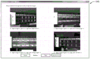
For example, FIGS. 5C and 5D depict example GUIs (530 and 540, respectively) in which a part to be inspected is verified. In this case, the image of the actual part may be superimposed on the dimensions of the part, for example, defined in the manner shown in fig. 5A and 5B described above. In doing so, the user may view and provide various inputs, for example, to confirm whether the defined dimensions of the part are consistent with the actual part being inspected. As described above, in some embodiments, the image may be enhanced with a visual indicator or "mask" that corresponds to the area occupied by the part (and therefore not passed by the optical head) and the area not occupied by the part (and therefore safe for the optical head). For example, referring to FIG. 5C (reflecting a top view of the part to be inspected), mask 532 may reflect an area or range corresponding to the position or pose of the object, while mask 534 may reflect an area or range where the optical head may be safely moved (and thus the parts should not overlap). As a further example, fig. 5D illustrates a mask 542, the mask 542 reflecting one or more regions or areas corresponding to the position or orientation of the part.
By way of yet another example, fig. 5E and 5F depict example GUIs (550 and 560, respectively) in which part definitions generated based on a CAD model (reflecting the size, shape, and/or other aspects/features of the part as described herein) are validated from images (captured by an inspection system and/or other sensors) of the actual part. As shown in fig. 5E and 5F, the image of the part (when introduced to the inspection system) may be superimposed on a representation of the part model, as reflected in the CAD model. In doing so, the user may, for example, confirm that such dimensions are accurate (as reflected in the captured image), reject when such dimensions are not accurate (e.g., based on the captured image), and/or modify/adjust the reference dimensions.
Upon verifying the definition of the part to be inspected (reflecting, for example, the size, shape, and/or other aspects/features of the part as described herein), the inspection system may create a dynamic plan to scan/inspect the part. Such a plan may reflect or include various instructions, operations, etc. that, when executed, may configure the described system to inspect a part. For example, images may be captured from many directions (e.g., with overlap) and/or using multiple lighting configurations (480). The set of images may be used to generate a MDM (multi-dimensional model) (490). Such a multi-dimensional model may include and/or otherwise encompass any number of aspects, elements, etc. of a part. For example, the reference multi-dimensional model may contain various aspects of the part (and/or regions, extents, etc. thereof), including but not limited to: size, shape, structure (two-dimensional, three-dimensional, etc.), material composition, etc.
After the described registration process, a visual representation of the part may be displayed (e.g., within a viewer/GUI). This may, for example, allow a user to specify various testing requirements (e.g., at the part level).
By way of illustration, fig. 6A depicts an example GUI 610 in which visual representations of various sizes/shapes of parts (e.g., as previously entered or determined) may be associated with images of actual parts captured at different locations, e.g., by an overlay of reference sizes, etc. with the captured part images. As shown in fig. 6A, a representation of the structure of part 612 (reflecting, for example, dimensions input by a user) may be overlaid with image 614 (e.g., an image of a part loaded into an inspection system captured by an optical head at a different position/angle). In doing so, the part may be visually represented/displayed as a collection of images that are displayed/superimposed as sliders in 3D space at the approximate location of the area where such images were acquired.
In other implementations, the part may be visually represented/displayed based on a CAD model of the part (or other such representation). For example, fig. 6B depicts an example GUI 620 in which visual representations of various sizes/shapes of a part are shown, as generated based on a CAD model of the part. In other embodiments, a preliminary scan of the part may be used to reconstruct a 3D model (which may be derived or calculated based on the generated MDM).
Using a reference GUI/viewer (e.g., as shown in fig. 6A-6B), a user may provide input to input various inspection/test requirements specifying a part level (e.g., as opposed to an image-based level). For example, by selecting or interacting with various controls (e.g., selectable buttons) as shown in fig. 6A and 6B. As shown in fig. 6A-6B, a user may adjust various aspects of the part view (e.g., rotation, zoom, etc.), and may further adjust various aspects of the part and/or the inspection to be applied thereto (e.g., how to capture one or more images of the part and/or portions thereof, conditions or configurations to be used in capturing and/or processing the reference images, etc.), as described herein. Specifying such requirements, etc., may be performed in an automated manner (e.g., based on CAD and initial scanning) or in a semi-manual manner (e.g., using Planner Motion Assistant (PMA) techniques as described below).
In some embodiments, after the described registration process, it may be desirable or advantageous to further inspect specific areas of the part, for example to define new inspection/test requirements. Fig. 7 depicts an example process/method 700 by which such further checks may be performed. In one embodiment, method 700 is performed by one or more elements depicted and/or described with respect to fig. 1 (including, but not limited to, system 100, device 150, an application executing at system 100 and/or device 150, etc.). In some other embodiments, one or more of the blocks of fig. 7 may be performed by one or more other machines.
In some embodiments, for example, a selection of a region of a part may be received. Such a selection may be received, for example, within a graphical user interface depicting, displaying, etc. the representation of the part, as described herein. Based on the received selection (e.g., selection of a region of the part), a location of the selected region (and/or other aspects) may be determined. Based on the determined location, various image capture parameters may be determined, calculated, and/or identified (e.g., as described herein). For example, parameters, settings, etc. that may generate a high quality image of the selected region may be determined. In some embodiments, an inspection path (which may be, for example, instructions related to the manner in which images of the selected area are to be acquired/captured) may be calculated for the part. Such an inspection path may be calculated, for example, based on the determined image capture parameters and/or the location of the selected region, as described herein. Additionally, in some embodiments, a reference inspection path may be calculated to avoid collisions between components of the inspection system (e.g., optical heads, robotic arms, etc.) and the component being inspected. The calculated inspection path may be performed, for example, for a part introduced into the inspection system.
By way of further illustration, an operator of the inspection system may provide input, such as by using a mouse (or any other input device/interface) to click/select a region/area within the part viewer/GUI (710). For example, fig. 8A-8B depict example GUIs (810 and 820, respectively) showing a scenario in which a user has selected a particular area or region of a part. This may generate/provide instructions to manipulate the optical head/robot arm to acquire an image of the selected area. To accomplish this task, the inspection system may resolve/determine the location and orientation of the selected point in 3D space (720). The system may then further determine/resolve a compatible configuration of the system (including, for example, parameters, settings, etc. as described herein) in which a relatively good/high quality image of the area may be taken (taking into account various system parameters, such as system range, working distance of the optical head, etc.) (730). It should be understood that the system configuration referenced may include the position of the robot and the external joints. Next, the inspection system may calculate a safe (e.g., collision free) and valid path from the current position of the optical head to the desired position (740) and execute the calculated path (750).
In some embodiments, one or more elements (e.g., components, component types and/or sub-types, etc.) included in a part can be identified, for example, within a model corresponding to a reference part. As described in detail herein, various test parameters may be associated with the identified elements. In some implementations, various selections of reference test parameters may be received (e.g., to associate such parameters with the identified elements). For example, an image of a reference part (e.g., as captured by the inspection system described) may be presented within a graphical user interface. Selection of various regions (e.g., selection of images corresponding to reference elements) may be received within a graphical user interface. As described herein, such selected region(s) may be associated with various test parameters (e.g., test parameters corresponding to or associated with the selected element).
By way of further illustration, various test/inspection requirements may be defined or specified after the described registration process. Fig. 9 depicts an example process/method 900 by which such requirements may be defined or specified 900. In one embodiment, method 900 is performed by one or more elements depicted and/or described with respect to fig. 1 (including, but not limited to, system 100, device 150, an application executing at system 100 and/or device 150, etc.). In some other embodiments, one or more of the blocks of fig. 9 may be performed by one or more other machines.
In some embodiments, an operator or administrator may enter or specify various requirements, parameters, etc. for a part. Such requirements, parameters, etc. may define or indicate various aspects of the manner in which the part (or a portion thereof) is to be inspected. In other embodiments, the inspection system may be configured to perform such functions in an automated or automated manner, for example, by inspecting components and/or sub-parts within the parts to be inspected and generating recommendations regarding requirements, parameters, etc. to apply to the testing/inspection of those parts. In doing so, the described inspection system may generate an inspection plan that, when executed, addresses or provides information about such requirements in an optimized/efficient manner.
In certain embodiments, the described inspection system may analyze the referenced MDM and/or preliminary dynamic part images to detect, segment, and/or classify general purpose components/elements (e.g., ports, screws, cables, etc.) (e.g., using computer vision and machine (depth) learning techniques/algorithms) (910, 920). For example, MDMs generated with respect to a part may be processed to identify ports or screws in the part that may need inspection. In some embodiments, such elements may be detected based on identification of comparable elements (screws, ports, etc.) relative to other portions.
Further, in some embodiments, the inspection system may process or analyze the CAD model (if any) to directly extract such components (e.g., screws, ports, etc.) that may need inspection. Such components may be identified or extracted based on various factors, such as semantic metadata and attributes (e.g., component model, brand, size, given name, etc.) of the components attached within the CAD model.
The inspection system may also classify the detected components into sub-types (e.g., RJ45 posts, philips screws, etc.) and/or suggest to the user that certain detected components should be tested (or automatically initiate such testing) (930). For example, a screw may be identified and then classified as a particular type of screw (e.g., a philips screw). As a further example, a port may be identified and subsequently classified as an RJ45 port. Such classification may enable inspection requirements associated with such component types to be applied to particular parts. Thus, in some embodiments, during inspection of a part (e.g., a philips screw) that is determined to include a particular component, the described inspection plan may include determining that the screw used is a philips screw (as opposed to other types).
As described above, in certain embodiments, a user or administrator may monitor and/or provide input or feedback regarding various aspects of the described processes. For example, the user may accept, edit, and/or reject various suggestions or suggestions generated by the inspection system, such as suggestions regarding applying certain tests to certain components/areas of the component (940).
The user may also manually define or add various inspection/testing requirements (950). For example, a user may select a test requirement (e.g., for a port). In doing so, the user may be further prompted to select other options, such as a subtype requirement (e.g., test port as an RJ45 port) (960). By way of illustration, fig. 10A depicts an example interface/GUI 1010 in which a user may select a port type (here RJ45) associated with a test/exam to be performed. As shown in fig. 10A, the identified port (e.g., an image 1012 of the port captured by the inspection system) may be presented to the user along with various options 1014 corresponding to the different port types. The user may select the port type corresponding to the port depicted in the image. In doing so, the test requirements/parameters associated with the selected port (e.g., determining whether the correct port type exists in the project) may be applied when checking the reference part.
In some embodiments, the user may also specify which of various available tests to perform, such as checking for springs, checking for housings, checking for foreign objects, etc. (970). For example, fig. 10B depicts an example interface/GUI 1020 in which a user may select an aspect, feature, etc. to be tested/inspected. As shown in FIG. 10B, one or more tests may be selected and associated with a particular component or area within a part. It should be understood that the reference test may include or reflect different types of inspection operations (e.g., capturing images of the reference component/area at different locations, different conditions, etc., and/or processing these images to calculate various determinations, e.g., whether a particular component is present, whether a scratch is present, etc.).
As noted, in certain embodiments, a region or component of a part may be selected, for example, to apply certain tests to the component/region so selected. For example, fig. 10C depicts an example GUI 1030 in which a user may select or mark a region/element (e.g., region or component 1032) and may further define inspection tests to be applied to such region, as well as other test requirements, settings, etc. (980), as described herein.
Further, in some embodiments, the user may provide input/feedback, such as accepting or rejecting various captured images. For example, fig. 10D depicts an example GUI 1040 in which various images captured by the inspection system described may be reviewed and accepted (e.g., by a user). By way of illustration, having identified and/or selected various components within the part and further selected/identified test parameters with respect to such elements/regions, various images (images corresponding to reference elements/regions under conditions defined by the selected/determined test requirements) may be presented to the user. The user can then select which images meet (or do not meet) the requirements of the reference exam.
Based on the described determinations and/or selections, an inspection plan (990) may be generated. In some embodiments, such an inspection plan may include and/or take into account identified/selected components/regions of the part, various testing requirements/parameters associated with such components/regions, and/or provided selections (e.g., that particular image meets/does not meet the requirements of the reference inspection). Upon execution, information about such requirements is processed or provided in an optimized/efficient manner.
In some implementations, one or more images of the part may be captured, for example, during execution of the inspection path (e.g., as described herein). Further, in some embodiments, various previously captured images may be loaded. Such images may be presented through a graphical user interface. A selection may be received regarding at least one of the captured images. Such a selection may, for example, accept or reject the captured image or images. Based on the selection of at least one of the reference captured images, an inspection plan may be generated for the part, and the inspection plan so generated may be executed for the reference part and/or other parts. In certain embodiments, such an inspection plan may be generated for a part based on a calculated inspection path and/or one or more image capture parameters, as described herein. In some embodiments, such an inspection plan may be adjusted to address one or more limitations of the inspection system described. Additionally, in some embodiments, various test parameters may be associated with at least one of the one or more images. For example, in some embodiments, one or more first test parameters may be associated with a first one of the one or more images and one or more second test parameters may be associated with a second one of the one or more images.
By way of further illustration, FIG. 11 depicts an example process 1100 by which an inspection plan may be generated. In one embodiment, method 1100 is performed by one or more elements depicted and/or described with respect to fig. 1 (including, but not limited to, system 100, device 150, an application executing at system 100 and/or device 150, etc.). In some other embodiments, one or more of the blocks of fig. 11 may be performed by one or more other machines.
In some embodiments, after the described test specification process (1110), the inspection system may generate a view (1120) (corresponding to an optical head configuration that may include position, illumination, etc.) from which it will acquire images during inspection. Such views may be presented to the user, who may be given the option of accepting/rejecting the view (1130). The accepted view may be added to the inspection plan for the part (1140). For these images, an image level test may be generated (1150) that meets defined test requirements (e.g., checking for the presence of a port spring in one of the images). The system may also generate a dynamic examination plan to acquire images and execute/implement the plan (during which the user may accept or reject captured images).
The inspection system may then further adjust, refine or optimize the generated acquisition path to achieve maximum efficiency. For example, in some embodiments, various hardware configurations (e.g., positions of the optical head, robotic arm, etc.) may be preferred (e.g., for capturing images under certain conditions), but may not be feasible (e.g., due to potential collisions of the optical head with other portions of the test object or the machine itself). Thus, the inspection system may refine or optimize such an inspection plan to address the constraints of the reference while obtaining results that meet (or approximate) the inspection requirements.
Additionally, in some embodiments, the inspection system may be further configured to perform as many reference inspections/tests as possible based on images that have already been captured (e.g., instead of capturing additional images of the same/similar area). Doing so may reduce the motion of various components (e.g., the optical head and the robotic arm) (as well as reduce the amount of redundant data acquired/processed).
Thus, it can be appreciated that the described techniques can and/or facilitate defining various test parameters, requirements, etc., with respect to a model of a part to be inspected, for example. The described techniques may further automatically convert reference parameters, requirements, etc. into a complete inspection plan. Such an inspection plan may include motion, acquisition, and/or test definitions that may specify operations, processes, tests, etc. that need to be run (e.g., over various computed/identified regions, areas, etc., such as within the generated image described), as well as parameters for which such operations, processes, tests, etc. apply to the test.
It should also be noted that although the described techniques and processes are primarily described herein with respect to product inspection (e.g., using an inspection system such as that depicted and described herein), the described techniques/processes are not so limited. Thus, the described techniques/processes may be similarly implemented and/or employed in other settings and contexts and for any number of additional objectives. As a result of such embodiments, further technical advantages, solutions, and/or improvements (beyond those described and/or referenced herein) may be achieved.
By way of illustration, in some embodiments, the described techniques may be employed for larger scale inspections, such as inspection of larger structures such as buildings, bridges, roads, tunnels, and the like. In such embodiments, a vehicle (equipped with various cameras, sensors, etc.) may be used to maneuver about such structures (e.g., around and/or inside). Examples of such vehicles include, but are not limited to, manned vehicles, such as automobiles, bicycles, and the like; unmanned vehicles, such as Unmanned Aerial Vehicles (UAVs) or "aircraft"; a remote control car, boat, etc., or any other such steerable device. In such embodiments, the reference vehicle or manipulandum may be configured to perform initial inspections (e.g., on prototypical or ideally constructed structures) and/or models defining ideal/expected dimensions and characteristics of such structures may be processed. This allows for the calculation of an inspection plan (e.g., the actual structure to be inspected, etc.). As described herein, various considerations may be considered in calculating such an inspection plan. For example, one or more important or critical areas of the structure to be inspected may be identified, and the path of vehicle maneuvers when performing the reference inspection may account for the priority of these areas. As a further example, certain technical limitations of the vehicle/equipment (e.g., battery limitations that may affect the time of flight of the drone, limitations that may or may not be traveling at the vehicle, altitude/acceptance limitations, etc.) may be considered in calculating the reference inspection plan. By doing so, the described techniques may enable the reference structure to be examined in the most efficient and effective manner. After the reference inspection plan is calculated, the vehicle may execute the plan, for example, in the manner described herein (e.g., with respect to product inspection).
It should also be understood that the components referred to herein may be combined or separated into other components, depending on the particular implementation. Additionally, in some embodiments, various components of a particular device may run on separate machines.
Some implementations are described herein as comprising logic or multiple components, modules, or mechanisms. The modules may constitute software modules (e.g., code embodied on a machine-readable medium) or hardware modules. A "hardware module" is a tangible unit that is capable of performing certain operations and may be configured or arranged in some physical manner. In various example implementations, one or more computer systems (e.g., a standalone computer system, a client computer system, or a server computer system) or one or more hardware modules (e.g., a processor or a set of processors) of a computer system may configure "hardware" by software (e.g., an application or application portion) to operate as a hardware module that performs certain operations described herein.
In some implementations, the hardware modules may be implemented mechanically, electronically, or any suitable combination thereof. For example, a hardware module may comprise dedicated circuitry or logic that is permanently configured to perform certain operations. For example, the hardware module may be a special purpose processor, such as a Field Programmable Gate Array (FPGA) or an Application Specific Integrated Circuit (ASIC). A hardware module may also include programmable logic or circuitry that is temporarily configured by software to perform certain operations. For example, a hardware module may include software executed by a general-purpose processor or other programmable processor. Once configured by such software, the hardware module becomes a specific machine (or a specific component of a machine) specifically tailored to perform the configured function, and is no longer a general purpose processor. Permanently configured circuits or temporarily configured circuits (e.g., configured by software) may be driven by cost and time considerations.
Thus, the phrase "hardware module" should be understood to include a tangible entity, either physically constructed, permanently configured (e.g., hardwired) or temporarily configured (e.g., programmed) to operate in a particular manner or to perform a particular operation described herein. As used herein, "hardware-implemented module" refers to a hardware module. Given an implementation in which the hardware modules are temporarily configured (e.g., programmed), each hardware module need not be configured or instantiated at any one instance in time. For example, where the hardware modules include a general-purpose processor configured by software to become a special-purpose processor, the general-purpose processor may be configured at different times to be different special-purpose processors (e.g., including different hardware modules), respectively. Thus, software configures one or more particular processors accordingly, e.g., to constitute a particular hardware module at one instance in time and to constitute a different hardware module at a different instance in time.
A hardware module may provide information to and receive information from other hardware modules. Thus, the described hardware modules may be considered to be communicatively coupled. In the case of multiple hardware modules being present at the same time, communication may be achieved by signal transmission (e.g., through appropriate circuits and buses) between two hardware modules or among multiple hardware modules. In implementations where multiple hardware modules are configured or instantiated at different times, communication between such hardware modules may be achieved, for example, by storing and retrieving information in memory structures accessible to the multiple hardware modules. For example, a hardware module may perform an operation and store the output of the operation in a storage device communicatively coupled thereto. Another hardware module may then access the storage device at a later time to extract and process the stored output. The hardware modules may also initiate communication with input or output devices and may operate on resources (e.g., collections of information).
Various operations of the example methods described herein may be performed, at least in part, by one or more processors that are temporarily configured (e.g., by software) or permanently configured to perform the relevant operations. Whether temporarily configured or permanently configured, such processors may constitute processor-implemented modules that operate to perform one or more operations or functions described herein. As used herein, "processor-implemented module" refers to a hardware module implemented using one or more processors.
Similarly, the methods described herein may be implemented at least in part by a processor, where one or more particular processors are examples of hardware. For example, at least some of the operations of a method may be performed by one or more processors or processor-implemented modules. Furthermore, the one or more processors may also support the performance of related operations in a "cloud computing" environment or as a "software as a service" (SaaS). For example, at least some of the operations may be performed by a set of computers (as an example of machines including processors) that are accessible via a network (e.g., the internet) and one or more appropriate interfaces (e.g., APIs).
The performance of certain operations may be distributed among the processors, not only residing in a single computer, but also being deployed across multiple computers. In some example implementations, the processors or processor-implemented modules may be located in a single geographic location (e.g., in a home environment, an office environment, or a server farm). In other example implementations, the processor or processor-implemented module may be distributed across multiple geographic locations.
The modules, methods, applications, etc. described in connection with fig. 1-11 are, in some embodiments, implemented in the context of a machine and associated software architecture. The following sections describe representative software and machine (e.g., hardware) architectures suitable for use with the disclosed implementations.
Software architectures are used in conjunction with hardware architectures to create devices and machines that are tailored to a specific purpose. For example, a particular hardware architecture in combination with a particular software architecture will create a mobile device, such as a mobile phone, tablet device, etc. Slightly different hardware and software architectures can produce smart devices for the "internet of things," while another combination can produce server computers for cloud computing architectures. Not all combinations of such software and hardware architectures are presented here, as those skilled in the art can readily understand how to implement the subject matter of the present invention in a context other than the disclosure contained herein.
Fig. 12 is a block diagram illustrating components of a machine 1200 capable of reading instructions from a machine-readable medium (e.g., a machine-readable storage medium) and performing any one or more of the methodologies discussed herein, according to some example embodiments. In particular, fig. 12 illustrates a schematic diagram of a machine 1200 in the example form of a computer system within which instructions 1216 (e.g., software, program, application, subroutine, application, or other executable code) for causing the machine 1200 to perform any one or more of the method logic discussed herein may be executed. Instructions 1216 transform the general-purpose, unprogrammed machine into a specific machine that is programmed to perform the functions described and illustrated in the described manner. In alternative embodiments, the machine 1200 operates as a standalone device or may be coupled (e.g., networked) to other machines. In a networked deployment, the machine 1200 may operate in the capacity of a server machine or a client machine in server-client network environment, or as a peer machine in a peer-to-peer (or distributed) network environment. The machine 1200 may include, but is not limited to, a server computer, a client computer, a PC, a tablet computer, a laptop computer, a netbook, a set-top box (STB), a Personal Digital Assistant (PDA), an entertainment media system, a cellular telephone, a smart phone, a mobile device, a wearable device (e.g., a smart watch), a smart home device (e.g., a smart device), other smart devices, a network device, a network router, a network switch, a network bridge, or any machine capable of executing the instructions 1216 sequentially or otherwise that specifies actions to be taken by the machine 1200. Further, while only a single machine 1200 is illustrated, the term "machine" shall also be taken to include a collection of machines 1200 that individually or jointly execute the instructions 1216 to perform any one or more of the methodologies discussed herein.
The machine 1200 may include a processor 1210, a memory/storage 1230, and I/O components 1250, which may be configured to communicate with each other, for example, via a bus 1202. In an example embodiment, processor 1210 (e.g., a Central Processing Unit (CPU), a Reduced Instruction Set Computing (RISC) processor, a Complex Instruction Set Computing (CISC) processor, a Graphics Processing Unit (GPU), a Digital Signal Processor (DSP), an ASIC, a Radio Frequency Integrated Circuit (RFIC), other processor, or any suitable combination thereof) may include, for example, processor 1212 and processor 1214, which may execute instructions 1216. The term "processor" is intended to include multi-core processors, which may include two or more independent processors (sometimes referred to as "cores") that may execute instructions concurrently. Although fig. 12 shows multiple processors 1210, the machine 1200 may also include a single processor with a single core, a single processor with multiple cores (e.g., a multi-core processor), multiple processors with a single core, multiple processors with multiple cores, or any combination thereof.
The memory/storage 1230 may include a memory 1232, such as a main memory or other storage, and a storage unit 1236, both of which may be accessed, such as by the processor 1210, via the bus 1202. The storage 1236 and the memory 1232 store instructions 1216 embodying any one or more of the methodologies or functions described herein. The instructions 1216 may also reside, completely or partially, within the memory 1232, within the storage unit 1236, within at least one of the processors 1210 (e.g., within a cache of the processor), or any suitable combination thereof during execution by the machine 1200. Thus, memory 1232, storage unit 1236, and the memory of processor 1210 are examples of machine-readable media.
As used herein, a "machine-readable medium" refers to a device capable of storing instructions (e.g., instructions 1216) and data, either temporarily or permanently, and may include, but is not limited to, Random Access Memory (RAM), Read Only Memory (ROM), cache memory, flash memory, optical media, magnetic media, cache memory, other types of memory (e.g., erasable programmable read only memory (EEPROM)), and/or any suitable combination thereof. The term "machine-readable medium" shall be taken to include a single medium or multiple media (e.g., a centralized or distributed database, or associated caches and servers) that are capable of storing the instructions 1216. The term "machine-readable medium" shall also be taken to include any medium, or combination of media, that is capable of storing instructions (e.g., instructions 1216) for execution by a machine (e.g., machine 1200), such that the "execution" of the instructions by the machine (e.g., processor 1210) causes the machine to perform any one or more of the methodologies discussed herein. Thus, "machine-readable medium" refers to a single storage device or appliance, as well as a "cloud-based" storage system or storage network that includes multiple storage devices or appliances. The term "machine-readable medium" does not include the signal itself.
I/O component 1250 may include a wide variety of components to receive input, provide output, generate output, send information, exchange information, capture measurements, and so forth. The particular I/O component 1250 included in a particular machine will depend on the type of machine. For example, a portable machine such as a mobile phone would likely include a touch input device or other such input mechanism, while a headless server machine would likely not include such a touch input device. It will be understood that the I/O component 1250 may include many other components not shown in fig. 12. The I/O components 1250 are grouped by function only to simplify the following discussion, and the grouping is in no way limiting. In various example embodiments, the I/O component 1250 may include an output component 1252 and an input component 1254. The output components 1252 may include visual components (e.g., a display such as a Plasma Display Panel (PDP), a Light Emitting Diode (LED)), a Liquid Crystal Display (LCD), a projector, or a Cathode Ray Tube (CRT)), acoustic components (e.g., speakers), tactile components (e.g., a vibration motor, a resistance mechanism), other signal generators, and so forth. The input components 1254 may include alphanumeric input components (e.g., a keyboard, a touch screen configured to receive alphanumeric input, an electro-optical keyboard, or other alphanumeric input components), point-based input components (e.g., a mouse, a touchpad, a trackball, a joystick, a motion sensor, or other pointing tool), tactile input components (e.g., physical buttons, a touch screen providing a location and/or force of a touch or touch gesture, or other tactile input components), audio input components (e.g., a microphone), and so forth.
In further example embodiments, the I/O components 1250 may include a biometric component 1256, a motion component 1258, an environmental component 1260, or a location component 1262, among a wide variety of other components. For example, the biometric component 1256 may include components for detecting expressions (e.g., hand expressions, facial expressions, voice expressions, body gestures, or eye tracking), measuring bio-signals (e.g., blood pressure, heart rate, body temperature, sweat, or brain waves), identifying a person (e.g., voice recognition, retinal recognition, facial recognition, fingerprint recognition, or electroencephalogram-based recognition), and so forth. The motion component 1258 may include an acceleration sensor component (e.g., an accelerometer), a gravity sensor component, a rotation sensor component (e.g., a gyroscope), and so forth. The environmental components 1260 may include, for example, lighting sensor components (e.g., photometer), temperature sensor components (e.g., one or more thermometers that detect ambient temperature), humidity sensor components, pressure sensor components (e.g., barometer), acoustic sensor components (e.g., one or more microphones that detect background noise), proximity sensor components (e.g., infrared sensors that detect nearby objects), gas sensors (e.g., gas detection sensors for safely detecting harmful gas concentrations or measuring contaminants), or other components that may provide an indication, measurement, or signal corresponding to the surrounding physical environment. The location component 1262 may include a location sensor component (e.g., a Global Positioning System (GPS) receiver component), an altitude sensor component (e.g., an altimeter or barometer that detects barometric pressure from which altitude may be derived), a direction sensor component (e.g., a magnetometer, etc.).
Communication may be accomplished using a variety of techniques. The I/O components 1250 may include a communications component 1264, the communications component 1264 operable to couple the machine 1200 to a network 1280 or a device 1270 via a coupling 1282 and a coupling 1272, respectively. For example, the communications component 1264 may include a network interface component or other suitable device that interfaces with the network 1280. In further examples, communications component 1264 can include a wired communications component, a wireless communications component, a cellular communications component, a Near Field Communications (NFC) component, a wireless communications component, The components (e.g.,
 low energy consumption),
 components and other communication components to provide communications by other means. Device 1270 may be any of a variety of other machines or peripheral devices (e.g., peripheral devices coupled via USB).
Further, communications component 1264 may detect the identifier or include a component operable to detect the identifier. For example, the communications component 1264 may include a Radio Frequency Identification (RFID) tag reader component, an NFC smart tag detection component, an optical reader component (e.g., an optical sensor for detecting one-dimensional barcodes such as Universal Product Code (UPC) barcodes, multi-dimensional barcodes (e.g., Quick Response (QR) codes, Aztec codes, Data Matrix (Data Matrix), Dataglyph, MaxiCode, PDF417, Ultra Code, UCC RSS-2D barcodes, and other optical codes), or an acoustic detection component (e.g., a microphone that identifies tagged audio signals). additionally, various information may be derived by the communications component 1264, e.g., location by Internet Protocol (IP) geolocation, location by identification of tagged audio signals, etc Signal triangulation for location determination, by detecting NFC beacon signals that may indicate a particular location, and so forth.
In various example implementations, one or more portions of network 1280 may be an ad hoc network, an intranet, an extranet, a Virtual Private Network (VPN), a Local Area Network (LAN), a wireless LAN (wlan), a WAN, a wireless WAN (wwan), a Metropolitan Area Network (MAN), the internet, a portion of the Public Switched Telephone Network (PSTN), a Plain Old Telephone Service (POTS) network, a cellular telephone network, a wireless network, a, A network, another type of network, or a combination of two or more such networks. For example, the network 1280 or a portion of the network 1280 may include a wireless or cellular network, and the
 coupling 1282 may be a Code Division Multiple Access (CDMA) connection, a global system for mobile communications (GSM) connection, or other type. In this example, the coupler 1282 may implement any of a number of types of data transmission technology, such as single carrier radio transmission technology (lxRTT), evolution-data optimized (EVDO) technology, General Packet Radio Service (GPRS) technology, enhanced GSM evolution (EDGE) technology, third generation partnership project (3GPP) including 3G, fourth generation wireless (4G) networks, Universal Mobile Telecommunications System (UMTS), High Speed Packet Access (HSPA), Worldwide Interoperability for Microwave Access (WiMAX), Long Term Evolution (LTE) standards, other standards defined by various standards-making organizations, other remote protocols, or other data transmission technologies.
The instructions 1216 may be transmitted or received over a network 1280 using a transmission medium via a network interface device (e.g., a network interface component included in the communications component 1264) and may utilize any of a variety of well-known transmission protocols (e.g., HTTP). Similarly, instructions 1216 may be sent or received to device 1270 via coupling 1272 (e.g., a peer-to-peer coupling) using a transmission medium. The term "transmission medium" shall be taken to include any intangible medium that is capable of storing, encoding or carrying instructions 1216 for execution by the machine 1200, and includes digital or analog communications signals or other intangible media to facilitate communication of such software.
Throughout the specification, multiple instances may implement a component, an operation, or a structure described as a single instance. Although individual operations of one or more methods are illustrated and described as separate operations, one or more of the individual operations may be performed concurrently and nothing requires that the operations be performed in the order illustrated. Structures and functionality presented as separate components in the example configurations may be implemented as a combined structure or component. Similarly, structures and functionality presented as a single component may be implemented as separate components. These and other variations, modifications, additions, and improvements fall within the scope of the subject matter herein.
Although the summary of the present subject matter has been described with reference to specific example embodiments, various modifications and changes may be made to the embodiments without departing from the broader scope of the embodiments of the disclosure. Such embodiments of the inventive subject matter may be referred to herein, individually or collectively, by the term "invention" merely for convenience and without intending to voluntarily limit the scope of this application to any single disclosure or inventive concept if more than one is in fact disclosed.
The embodiments illustrated herein are described in sufficient detail to enable those skilled in the art to practice the disclosed teachings. Other embodiments may be utilized and derived therefrom, such that structural and logical substitutions and changes may be made without departing from the scope of this disclosure. The detailed description is, therefore, not to be taken in a limiting sense, and the scope of various embodiments is defined only by the appended claims, along with the full range of equivalents to which such claims are entitled.
As used herein, the term "or" may be interpreted in an inclusive or exclusive sense. Furthermore, multiple instances may be provided as a single instance for a resource, operation, or structure described herein. In addition, the boundaries between the various resources, operations, modules, engines, and data stores are somewhat arbitrary, and particular operations are illustrated in the context of specific illustrative configurations. Other allocations of functionality are envisioned and may fall within the scope of various implementations of the disclosure. In general, structures and functionality presented as separate resources in the example configurations may be implemented as a combined structure or resource. Similarly, structures and functionality presented as a single resource may be implemented as separate resources. These and other variations, modifications, additions, and improvements fall within the scope of the implementations of the disclosure as expressed in the following claims. The specification and drawings are, accordingly, to be regarded in an illustrative rather than a restrictive sense.
Claims (55)
1. A system, comprising:
a processing device; and
a memory coupled to the processing device and storing instructions that, when executed by the processing device, cause the system to:
receiving, within a graphical user interface depicting a representation of a part, a selection of an area of the part;
determining a location of a selected region based on a selection of a region of the part;
determining one or more image capture parameters based on the determined location;
calculating an inspection path for the part based on (a) the determined image capture parameters and (b) the location of the selected region; and
executing, by an inspection system, the calculated inspection path for the part.
2. The system of claim 1, wherein the inspection path includes one or more instructions to acquire one or more images of the selected region.
3. The system of claim 1, wherein calculating an inspection path comprises: the inspection path is calculated to avoid a collision between one or more elements of the inspection system and the part.
4. The system of claim 1, wherein the memory further stores instructions to cause the system to perform operations comprising identifying one or more elements within the model of the part.
5. The system of claim 4, wherein determining one or more image capture parameters comprises: one or more test parameters associated with the identified one or more elements are determined.
6. The system of claim 4, wherein determining one or more image capture parameters comprises: a selection of one or more test parameters associated with the identified one or more elements is received.
7. The system of claim 4, wherein identifying one or more elements comprises: identifying a component type contained within the part.
8. The system of claim 4, wherein identifying one or more elements comprises: identifying a component subtype contained within the part.
9. The system of claim 4, wherein identifying one or more elements comprises:
presenting one or more images of the part in a graphical user interface;
receiving, in a graphical user interface, a selection of one or more regions of the one or more images corresponding to the one or more elements; and
the selected one or more regions are associated with one or more test parameters corresponding to the selected component.
10. The system of claim 1, wherein the memory further stores instructions to cause the system to:
capturing one or more images of the part during execution of the inspection path;
presenting the one or more images through a graphical user interface;
receiving a selection of at least one of the captured one or more images; and
an inspection plan for the part is generated based on the selection of at least one of the captured one or more images.
11. The system of claim 10, wherein capturing one or more images comprises: loading one or more previously captured images of the part.
12. The system of claim 10, wherein receiving a selection for at least one of the captured one or more images comprises: receiving a selection that accepts or rejects at least one of the captured one or more images.
13. The system of claim 10, wherein generating an inspection plan comprises: an inspection plan is generated for the part based on (a) the calculated inspection path and (b) the one or more image capture parameters.
14. The system of claim 10, wherein generating an inspection plan comprises: an inspection plan is adjusted to meet one or more limitations of the inspection system.
15. The system of claim 10, wherein generating an inspection plan comprises: associating one or more test parameters with at least one of the one or more images.
16. The system of claim 10, wherein generating an inspection plan comprises: one or more first test parameters are associated with a first image of the one or more images and one or more second test parameters are associated with a second image of the one or more images.
17. The system of claim 10, wherein the memory further stores instructions to cause the system to perform operations comprising executing the generated inspection plan for the part.
18. The system of claim 10, wherein the memory further stores instructions to cause the system to perform operations comprising executing the generated inspection plan for another part.
19. The system of claim 1, wherein the memory further stores instructions to cause the system to:
identifying a model reflecting a representation of the part;
calculating one or more dimensions of the part based on the model;
capturing one or more images of the part;
associating the captured one or more images with the calculated dimensions; and
the calculated dimensions are validated based on the association of the captured one or more images.
20. The system of claim 19, wherein identifying a model comprises: a CAD model of the part is identified.
21. The system of claim 19, wherein identifying a model comprises: one or more inputs corresponding to one or more dimensions of the part are received.
22. The system of claim 19, wherein identifying a model comprises: one or more inputs corresponding to a shape of the part are received.
23. The system of claim 19, wherein identifying a model comprises: one or more inputs corresponding to a template reflecting one or more dimensions of the part are received.
24. The system of claim 19, wherein associating the captured one or more images with the calculated dimensions comprises: presenting, via a graphical user interface, at least one of the captured one or more images for a representation of the one or more dimensions of the part.
25. The system of claim 19, wherein verifying the calculated dimensions comprises: one or more inputs corresponding to the association of the captured one or more images with the calculated dimensions of the part are received.
26. The system of claim 25, wherein the one or more inputs reflect: the calculated one or more dimensions are accurate relative to the part depicted in the one or more images.
27. The system of claim 25, wherein the one or more inputs reflect: the calculated one or more dimensions are inaccurate relative to the part depicted in the one or more images.
28. The system of claim 25, wherein verifying the calculated dimensions further comprises: adjusting one or more of the calculated dimensions based on the one or more inputs.
29. The system of claim 1, wherein the memory further stores instructions to cause the system to:
receiving one or more inputs corresponding to one or more aspects of the part;
capturing one or more images of the part;
associating the captured one or more images with the one or more aspects; and
the received one or more aspects are verified based on the association of the captured one or more images.
30. The system of claim 29, wherein receiving one or more inputs comprises: a selection of a CAD model of the part is received.
31. The system of claim 29, wherein receiving one or more inputs comprises: one or more inputs corresponding to one or more dimensions of the part are received.
32. The system of claim 29, wherein receiving one or more inputs comprises: one or more inputs corresponding to a shape of the part are received.
33. The system of claim 29, wherein receiving one or more inputs comprises: one or more inputs corresponding to a template reflecting one or more dimensions of the part are received.
34. The system of claim 29, wherein associating the captured one or more images comprises: presenting, via a graphical user interface, at least one of the captured one or more images for a representation of the one or more aspects of the part.
35. The system of claim 29, wherein verifying the one or more aspects comprises: one or more user inputs corresponding to the association of the captured one or more images with the one or more aspects of the part are received.
36. The system of claim 35, wherein the one or more user inputs reflect: the one or more aspects are accurate with respect to the part depicted in the one or more images.
37. The system of claim 35, wherein the one or more user inputs reflect: the one or more aspects are inaccurate relative to the part depicted in the one or more images.
38. The system of claim 35, wherein verifying the calculated dimensions further comprises: adjusting one or more of the received aspects of the part based on the one or more user inputs.
39. The system of claim 1, wherein the memory further stores instructions to cause the system to:
receiving one or more inputs corresponding to one or more dimensions of the part;
capturing one or more images of the part;
associating the captured one or more images with the one or more dimensions; and
the received dimensions are verified based on the association of the captured one or more images.
40. The system of claim 39, wherein associating the captured one or more images with the received one or more inputs comprises: presenting, through a graphical user interface, at least one of the captured one or more images as an overlay with respect to a representation of one or more dimensions of the part.
41. The system of claim 39, wherein verifying the calculated dimensions comprises: one or more user inputs are received through a graphical user interface that depicts at least one of the captured one or more images as an overlay with respect to a representation of one or more images of the part.
42. The system of claim 41, wherein verifying the calculated dimensions further comprises: adjusting one or more of the received dimensions based on the one or more user inputs.
43. The system of claim 1, wherein the memory further stores instructions to cause the system to:
determining a model reflecting a representation of a fixture;
calculating one or more dimensions of the fixture based on the model;
capturing one or more images of the fixture;
associating the captured one or more images of the fixture with the calculated dimensions of the fixture; and
verifying the calculated dimensions of the fixture based on the association of the captured one or more images.
44. The system of claim 43, wherein the fixture comprises a fixture configured to support the part within the inspection system.
45. The system of claim 43, wherein identifying a model comprises: a CAD model of the fixture is identified.
46. The system of claim 43, wherein identifying a model comprises: one or more inputs corresponding to one or more dimensions of the fixture are received.
47. The system of claim 43, wherein identifying a model comprises: one or more inputs corresponding to a shape of the fixture are received.
48. The system of claim 43, wherein identifying a model comprises: one or more inputs corresponding to a template reflecting one or more dimensions of the fixture are received.
49. The system of claim 43, wherein associating the captured one or more images with the calculated dimensions comprises: presenting, via a graphical user interface, at least one of the captured one or more images for a representation of one or more dimensions of the fixture.
50. The system of claim 43, wherein verifying the calculated dimensions comprises: receiving one or more inputs corresponding to the association of the captured one or more images with the calculated dimensions of the fixture.
51. The system of claim 50, wherein the one or more inputs reflect: the calculated one or more dimensions are accurate relative to the fixture depicted in the one or more images.
52. The system of claim 50, wherein the one or more inputs reflect: the calculated one or more dimensions are inaccurate relative to the fixture depicted in the one or more images.
53. The system of claim 50, wherein verifying the calculated dimensions further comprises: adjusting one or more of the calculated dimensions based on the one or more inputs.
54. A method, comprising:
receiving, within a graphical user interface depicting a representation of a part, a selection of an area of the part;
determining a location of a selected region based on a selection of a region of the part;
determining one or more image capture parameters based on the determined location;
calculating an inspection path for the part based on (a) the determined image capture parameters and (b) the location of the selected region;
capturing one or more images of the part during execution of the inspection path;
presenting the captured one or more images through a graphical user interface;
receiving a selection of at least one of the captured one or more images;
associating one or more test parameters with at least one of the captured one or more images based on the selection; and
an inspection plan is generated for the part based on the associated one or more test parameters.
55. A non-transitory computer-readable medium having instructions stored thereon that, when executed by a processing device, cause the processing device to:
identifying a model reflecting a representation of the part;
calculating one or more dimensions of the part based on the model;
capturing one or more images of the part;
associating the captured one or more images with the calculated dimensions;
verifying the calculated dimensions based on the association of the captured one or more images;
receiving, within a graphical user interface depicting a representation of the part, a selection of an area of the part;
determining a location of a selected region based on a selection of a region of the part;
determining one or more image capture parameters based on the determined position and the calculated dimensions of the part;
calculating an inspection path for the part based on (a) the determined image capture parameters, (b) the location of the selected area, and (c) the calculated dimensions of the part;
capturing one or more images of the part during execution of the inspection path;
presenting the captured one or more images through a graphical user interface;
receiving a selection of at least one of the captured one or more images;
associating one or more test parameters with at least one of the captured one or more images based on the selection;
generating an inspection plan for the part based on the associated one or more test parameters; and
executing the generated inspection plan on the part by an inspection system.
Applications Claiming Priority (3)
| Application Number | Priority Date | Filing Date | Title |
|---|---|---|---|
| US201862617312P | 2018-01-15 | 2018-01-15 | |
| US62/617,312 | 2018-01-15 | ||
| PCT/US2019/013720 WO2019156783A1 (en) | 2018-01-15 | 2019-01-15 | Automated inspection and part enrollment |
Publications (1)
| Publication Number | Publication Date |
|---|---|
| CN112585672A true CN112585672A (en) | 2021-03-30 |
Family
ID=67549747
Family Applications (1)
| Application Number | Title | Priority Date | Filing Date |
|---|---|---|---|
| CN201980019230.3A Pending CN112585672A (en) | 2018-01-15 | 2019-01-15 | Automated inspection and parts registration |
Country Status (6)
| Country | Link |
|---|---|
| US (1) | US20210082105A1 (en) |
| EP (1) | EP3740948A4 (en) |
| JP (2) | JP2021511594A (en) |
| CN (1) | CN112585672A (en) |
| IL (1) | IL276058A (en) |
| WO (1) | WO2019156783A1 (en) |
Families Citing this family (1)
| Publication number | Priority date | Publication date | Assignee | Title |
|---|---|---|---|---|
| US20230410364A1 (en) * | 2020-09-29 | 2023-12-21 | Kitov Systems Ltd | Semantic segmentation of inspection targets |
Citations (8)
| Publication number | Priority date | Publication date | Assignee | Title |
|---|---|---|---|---|
| JPH08304581A (en) * | 1995-04-28 | 1996-11-22 | Toshiba Corp | Device and method for plant inspection support |
| US20130278725A1 (en) * | 2012-04-24 | 2013-10-24 | Connecticut Center for Advanced Technology, Inc. | Integrated Structured Light 3D Scanner |
| CN103380057A (en) * | 2010-09-29 | 2013-10-30 | 航空机器股份有限公司 | Novel systems and methods for non-destructive inspection of airplanes |
| US20150012171A1 (en) * | 2013-07-02 | 2015-01-08 | Premium Aerotec Gmbh | Assembly inspection system and method |
| WO2016018717A1 (en) * | 2014-07-29 | 2016-02-04 | Plethora Corporation | System and method for automated object measurement |
| US20160195390A1 (en) * | 2015-01-05 | 2016-07-07 | Bell Helicopter Textron Inc. | Inspecting components using mobile robotic inspection systems |
| WO2016179186A1 (en) * | 2015-05-04 | 2016-11-10 | Mitutoyo Corporation | Inspection program editing environment providing user defined collision avoidance volumes |
| CN107408297A (en) * | 2014-11-24 | 2017-11-28 | 基托夫系统有限公司 | It is automatic to check |
Family Cites Families (9)
| Publication number | Priority date | Publication date | Assignee | Title |
|---|---|---|---|---|
| GB0210990D0 (en) * | 2002-05-14 | 2002-06-19 | Rolls Royce Plc | Method of generating an inspection program and method of generating a visual display |
| DE102004007829B4 (en) * | 2004-02-18 | 2007-04-05 | Isra Vision Systems Ag | Method for determining areas to be inspected |
| US7337651B2 (en) * | 2005-04-05 | 2008-03-04 | General Electric Company | Method for performing model based scanplan generation of a component under inspection |
| US9363487B2 (en) * | 2005-09-08 | 2016-06-07 | Avigilon Fortress Corporation | Scanning camera-based video surveillance system |
| DE102009029061A1 (en) * | 2008-09-05 | 2010-03-11 | Mori Seiki Co., Ltd., Yamatokoriyama-shi | Method and device for processing status check |
| US20140293047A1 (en) * | 2013-04-02 | 2014-10-02 | Caterpillar Inc. | System for generating overhead view of machine |
| US9639083B2 (en) * | 2013-12-18 | 2017-05-02 | Mitutoyo Corporation | System and method for programming workpiece feature inspection operations for a coordinate measuring machine |
| US11520472B2 (en) * | 2015-09-24 | 2022-12-06 | Mitutoyo Corporation | Inspection program editing environment including integrated alignment program planning and editing features |
| US10018465B2 (en) * | 2015-09-25 | 2018-07-10 | General Electric Company | Inspection path display |
-
2019
- 2019-01-15 CN CN201980019230.3A patent/CN112585672A/en active Pending
- 2019-01-15 JP JP2020540285A patent/JP2021511594A/en active Pending
- 2019-01-15 US US16/962,496 patent/US20210082105A1/en active Pending
- 2019-01-15 WO PCT/US2019/013720 patent/WO2019156783A1/en active Search and Examination
- 2019-01-15 EP EP19751933.3A patent/EP3740948A4/en active Pending
-
2020
- 2020-07-15 IL IL276058A patent/IL276058A/en unknown
-
2023
- 2023-12-07 JP JP2023207156A patent/JP2024026316A/en active Pending
Patent Citations (9)
| Publication number | Priority date | Publication date | Assignee | Title |
|---|---|---|---|---|
| JPH08304581A (en) * | 1995-04-28 | 1996-11-22 | Toshiba Corp | Device and method for plant inspection support |
| CN103380057A (en) * | 2010-09-29 | 2013-10-30 | 航空机器股份有限公司 | Novel systems and methods for non-destructive inspection of airplanes |
| US20160318632A1 (en) * | 2010-09-29 | 2016-11-03 | Aerobotics, Inc. | Novel systems and methods for non-destructive inspection of airplanes |
| US20130278725A1 (en) * | 2012-04-24 | 2013-10-24 | Connecticut Center for Advanced Technology, Inc. | Integrated Structured Light 3D Scanner |
| US20150012171A1 (en) * | 2013-07-02 | 2015-01-08 | Premium Aerotec Gmbh | Assembly inspection system and method |
| WO2016018717A1 (en) * | 2014-07-29 | 2016-02-04 | Plethora Corporation | System and method for automated object measurement |
| CN107408297A (en) * | 2014-11-24 | 2017-11-28 | 基托夫系统有限公司 | It is automatic to check |
| US20160195390A1 (en) * | 2015-01-05 | 2016-07-07 | Bell Helicopter Textron Inc. | Inspecting components using mobile robotic inspection systems |
| WO2016179186A1 (en) * | 2015-05-04 | 2016-11-10 | Mitutoyo Corporation | Inspection program editing environment providing user defined collision avoidance volumes |
Also Published As
| Publication number | Publication date |
|---|---|
| WO2019156783A1 (en) | 2019-08-15 |
| IL276058A (en) | 2020-08-31 |
| US20210082105A1 (en) | 2021-03-18 |
| EP3740948A1 (en) | 2020-11-25 |
| EP3740948A4 (en) | 2021-10-27 |
| JP2024026316A (en) | 2024-02-28 |
| JP2021511594A (en) | 2021-05-06 |
Similar Documents
| Publication | Publication Date | Title |
|---|---|---|
| CN107408297B (en) | Automatic inspection | |
| US11431896B2 (en) | Augmented reality for three-dimensional model reconstruction | |
| US11893611B2 (en) | Document optical character recognition | |
| JP6786762B2 (en) | A method and device for controlling a device having an image collecting unit and a distance measuring unit. | |
| US20150015602A1 (en) | System and method for selective determination of point clouds | |
| CN110726724A (en) | Defect detection method, system and device | |
| US20200273200A1 (en) | Camera localization based on skeletal tracking | |
| JP2024026316A (en) | Automated inspection and part enrollment | |
| CN110910628A (en) | Interactive processing method and device for vehicle damage image shooting and electronic equipment | |
| Saif et al. | Development of a smart system based on STEP-NC for machine vision inspection with IoT environmental | |
| EP4009038A1 (en) | Method and device for detecting mechanical equipment parts | |
| CN111389750B (en) | Vision measurement system and measurement method | |
| CN108564626B (en) | Method and apparatus for determining relative pose angle between cameras mounted to an acquisition entity | |
| Parkot | Robotic station for vision inspection of product quality | |
| KR20170045631A (en) | Method for inspecting product based on vector modeling and Apparatus thereof | |
| CN117392079A (en) | Appearance defect detection method and device, visual detection system and electronic equipment | |
| CN116189020A (en) | Unmanned aerial vehicle line patrol navigation method and system based on infrared image power line identification | |
| CN117218104A (en) | Appearance detection method and system for electronic detonator module, storage medium and electronic equipment | |
| CN115482185A (en) | Airplane surface defect detection method and system, storage medium and terminal |
Legal Events
| Date | Code | Title | Description |
|---|---|---|---|
| PB01 | Publication | ||
| PB01 | Publication | ||
| SE01 | Entry into force of request for substantive examination | ||
| SE01 | Entry into force of request for substantive examination |