CN112424833A - Three-dimensional data encoding method, three-dimensional data decoding method, three-dimensional data encoding device, and three-dimensional data decoding device - Google Patents
Three-dimensional data encoding method, three-dimensional data decoding method, three-dimensional data encoding device, and three-dimensional data decoding device Download PDFInfo
- Publication number
- CN112424833A CN112424833A CN201980046320.1A CN201980046320A CN112424833A CN 112424833 A CN112424833 A CN 112424833A CN 201980046320 A CN201980046320 A CN 201980046320A CN 112424833 A CN112424833 A CN 112424833A
- Authority
- CN
- China
- Prior art keywords
- dimensional
- dimensional data
- information
- data
- encoding
- Prior art date
- Legal status (The legal status is an assumption and is not a legal conclusion. Google has not performed a legal analysis and makes no representation as to the accuracy of the status listed.)
- Pending
Links
Images


Classifications
-
- H—ELECTRICITY
- H04—ELECTRIC COMMUNICATION TECHNIQUE
- H04N—PICTORIAL COMMUNICATION, e.g. TELEVISION
- H04N19/00—Methods or arrangements for coding, decoding, compressing or decompressing digital video signals
- H04N19/50—Methods or arrangements for coding, decoding, compressing or decompressing digital video signals using predictive coding
- H04N19/597—Methods or arrangements for coding, decoding, compressing or decompressing digital video signals using predictive coding specially adapted for multi-view video sequence encoding
-
- G—PHYSICS
- G06—COMPUTING; CALCULATING OR COUNTING
- G06T—IMAGE DATA PROCESSING OR GENERATION, IN GENERAL
- G06T9/00—Image coding
- G06T9/40—Tree coding, e.g. quadtree, octree
-
- G—PHYSICS
- G06—COMPUTING; CALCULATING OR COUNTING
- G06T—IMAGE DATA PROCESSING OR GENERATION, IN GENERAL
- G06T9/00—Image coding
-
- G—PHYSICS
- G06—COMPUTING; CALCULATING OR COUNTING
- G06T—IMAGE DATA PROCESSING OR GENERATION, IN GENERAL
- G06T9/00—Image coding
- G06T9/001—Model-based coding, e.g. wire frame
-
- H—ELECTRICITY
- H04—ELECTRIC COMMUNICATION TECHNIQUE
- H04N—PICTORIAL COMMUNICATION, e.g. TELEVISION
- H04N19/00—Methods or arrangements for coding, decoding, compressing or decompressing digital video signals
- H04N19/10—Methods or arrangements for coding, decoding, compressing or decompressing digital video signals using adaptive coding
- H04N19/169—Methods or arrangements for coding, decoding, compressing or decompressing digital video signals using adaptive coding characterised by the coding unit, i.e. the structural portion or semantic portion of the video signal being the object or the subject of the adaptive coding
- H04N19/17—Methods or arrangements for coding, decoding, compressing or decompressing digital video signals using adaptive coding characterised by the coding unit, i.e. the structural portion or semantic portion of the video signal being the object or the subject of the adaptive coding the unit being an image region, e.g. an object
- H04N19/176—Methods or arrangements for coding, decoding, compressing or decompressing digital video signals using adaptive coding characterised by the coding unit, i.e. the structural portion or semantic portion of the video signal being the object or the subject of the adaptive coding the unit being an image region, e.g. an object the region being a block, e.g. a macroblock
-
- H—ELECTRICITY
- H04—ELECTRIC COMMUNICATION TECHNIQUE
- H04N—PICTORIAL COMMUNICATION, e.g. TELEVISION
- H04N19/00—Methods or arrangements for coding, decoding, compressing or decompressing digital video signals
- H04N19/10—Methods or arrangements for coding, decoding, compressing or decompressing digital video signals using adaptive coding
- H04N19/169—Methods or arrangements for coding, decoding, compressing or decompressing digital video signals using adaptive coding characterised by the coding unit, i.e. the structural portion or semantic portion of the video signal being the object or the subject of the adaptive coding
- H04N19/184—Methods or arrangements for coding, decoding, compressing or decompressing digital video signals using adaptive coding characterised by the coding unit, i.e. the structural portion or semantic portion of the video signal being the object or the subject of the adaptive coding the unit being bits, e.g. of the compressed video stream
-
- H—ELECTRICITY
- H04—ELECTRIC COMMUNICATION TECHNIQUE
- H04N—PICTORIAL COMMUNICATION, e.g. TELEVISION
- H04N19/00—Methods or arrangements for coding, decoding, compressing or decompressing digital video signals
- H04N19/70—Methods or arrangements for coding, decoding, compressing or decompressing digital video signals characterised by syntax aspects related to video coding, e.g. related to compression standards
Landscapes
- Engineering & Computer Science (AREA)
- Multimedia (AREA)
- Signal Processing (AREA)
- Physics & Mathematics (AREA)
- General Physics & Mathematics (AREA)
- Theoretical Computer Science (AREA)
- Compression Or Coding Systems Of Tv Signals (AREA)
- Testing, Inspecting, Measuring Of Stereoscopic Televisions And Televisions (AREA)
- Image Processing (AREA)
Abstract
A three-dimensional data encoding method generates a bit stream including a plurality of encoded data corresponding to a plurality of subspaces by encoding a plurality of subspaces included in an object space including a plurality of three-dimensional points, and in the generation of the bit stream, a list of information of the plurality of subspaces associated with a plurality of identifiers assigned to the plurality of subspaces is stored in 1 st control information common to the plurality of encoded data included in the bit stream (S4531), and an identifier assigned to a subspace corresponding to the encoded data is stored in a header of each of the plurality of encoded data (S4532).
Description
Technical Field
The present disclosure relates to a three-dimensional data encoding method, a three-dimensional data decoding method, a three-dimensional data encoding device, and a three-dimensional data decoding device.
Background
In a wide field of computer vision, map information, monitoring, infrastructure inspection, image distribution, and the like for autonomously operating an automobile or a robot, a device or service that flexibly uses three-dimensional data will be popularized in the future. The three-dimensional data is obtained by various methods such as a range finder equidistant sensor, a stereo camera, or a combination of a plurality of monocular cameras.
One expression method of three-dimensional data is an expression method called a point cloud, which expresses the shape of a three-dimensional structure by a group of points in a three-dimensional space. The positions and colors of the point groups are stored in the point cloud. Although it is expected that point clouds will be the mainstream as a method of expressing three-dimensional data, the data amount of the point group is very large. Therefore, in the storage or transmission of three-dimensional data, it is necessary to compress the amount of data by encoding, as in the case of two-dimensional moving images (for example, MPEG-4AVC, HEVC, or the like standardized by MPEG).
In addition, some of the compression of the Point Cloud is supported by a public Library (Point Cloud Library) or the like that performs processing for Point Cloud association.
There is also known a technique of searching for and displaying facilities around a vehicle using three-dimensional map data (see, for example, patent document 1).
Documents of the prior art
Patent document
Disclosure of Invention
Problems to be solved by the invention
In encoding and decoding three-dimensional data, it is desirable to reduce the amount of processing of a three-dimensional data decoding device.
An object of the present disclosure is to provide a three-dimensional data encoding method, a three-dimensional data decoding method, a three-dimensional data encoding device, or a three-dimensional data decoding device that can reduce the amount of processing of the three-dimensional data decoding device.
Means for solving the problems
A three-dimensional data encoding method according to an aspect of the present disclosure generates a bitstream including a plurality of encoded data corresponding to a plurality of subspaces by encoding the plurality of subspaces included in an object space including a plurality of three-dimensional points, stores a list of information of the plurality of subspaces associated with a plurality of identifiers assigned to the plurality of subspaces in 1 st control information common to the plurality of encoded data included in the bitstream, and stores an identifier assigned to the subspace corresponding to the encoded data in a header of each of the plurality of encoded data.
A three-dimensional data decoding method according to an aspect of the present disclosure decodes a bitstream that is obtained by encoding a plurality of subspaces included in a target space including a plurality of three-dimensional points and that includes a plurality of encoded data corresponding to the plurality of subspaces, determines a subspace to be decoded of the plurality of subspaces in decoding the bitstream, and obtains encoded data of the subspace to be decoded using a list of information of the plurality of subspaces associated with a plurality of identifiers included in 1 st control information that is common to the plurality of encoded data and included in a header of each of the plurality of encoded data and an identifier allocated to the subspace corresponding to the encoded data.
Effects of the invention
The present disclosure can provide a three-dimensional data encoding method, a three-dimensional data decoding method, a three-dimensional data encoding device, or a three-dimensional data decoding device that can reduce the processing amount of the three-dimensional data decoding device.
Drawings
Fig. 1 shows a configuration of encoded three-dimensional data according to embodiment 1.
Fig. 2 shows an example of the prediction structure between SPCs belonging to the lowermost layer of GOS in embodiment 1.
Fig. 3 shows an example of the inter-layer prediction structure of embodiment 1.
Fig. 4 shows an example of the coding order of GOS according to embodiment 1.
Fig. 5 shows an example of the coding order of GOS according to embodiment 1.
Fig. 6 is a block diagram of a three-dimensional data encoding device according to embodiment 1.
Fig. 7 is a flowchart of the encoding process according to embodiment 1.
Fig. 8 is a block diagram of a three-dimensional data decoding device according to embodiment 1.
Fig. 9 is a flowchart of the decoding process according to embodiment 1.
Fig. 10 shows an example of meta information of embodiment 1.
Fig. 11 shows an example of the SWLD configuration of embodiment 2.
Fig. 12 shows an example of operations of the server and the client according to embodiment 2.
Fig. 13 shows an operation example of the server and the client according to embodiment 2.
Fig. 14 shows an example of operations of the server and the client according to embodiment 2.
Fig. 15 shows an operation example of the server and the client according to embodiment 2.
Fig. 16 is a block diagram of a three-dimensional data encoding device according to embodiment 2.
Fig. 17 is a flowchart of the encoding process according to embodiment 2.
Fig. 18 is a block diagram of a three-dimensional data decoding device according to embodiment 2.
Fig. 19 is a flowchart of the decoding process in embodiment 2.
Fig. 20 shows an example of the WLD configuration of embodiment 2.
Fig. 21 shows an example of an octree structure of WLD of embodiment 2.
Fig. 22 shows an example of the SWLD configuration of embodiment 2.
Fig. 23 shows an example of an octree structure of the SWLD of embodiment 2.
Fig. 24 is a block diagram of a three-dimensional data creating device according to embodiment 3.
Fig. 25 is a block diagram of a three-dimensional data transmission device according to embodiment 3.
Fig. 26 is a block diagram of a three-dimensional information processing apparatus according to embodiment 4.
Fig. 27 is a block diagram of a three-dimensional data creating device according to embodiment 5.
Fig. 28 shows a configuration of a system of embodiment 6.
Fig. 29 is a block diagram of a client device according to embodiment 6.
Fig. 30 is a block diagram of a server according to embodiment 6.
Fig. 31 is a flowchart of a three-dimensional data creation process performed by the client device according to embodiment 6.
Fig. 32 is a flowchart of sensor information transmission processing performed by the client device according to embodiment 6.
Fig. 33 is a flowchart of three-dimensional data creation processing performed by the server according to embodiment 6.
Fig. 34 is a flowchart of three-dimensional map transmission processing performed by the server according to embodiment 6.
Fig. 35 shows a configuration of a modification of the system of embodiment 6.
Fig. 36 shows the configuration of the server and client device according to embodiment 6.
Fig. 37 is a block diagram of a three-dimensional data encoding device according to embodiment 7.
Fig. 38 shows an example of a prediction residual in embodiment 7.
Fig. 39 shows an example of the volume of embodiment 7.
Fig. 40 shows an example of octree representation of the volume of embodiment 7.
Fig. 41 shows an example of a bit string of a volume in embodiment 7.
Fig. 42 shows an example of octree representation of the volume of embodiment 7.
Fig. 43 shows an example of the volume of embodiment 7.
Fig. 44 is a diagram for explaining the intra prediction processing according to embodiment 7.
Fig. 45 is a diagram showing a configuration of a distribution system according to embodiment 8.
Fig. 46 is a diagram showing an example of the configuration of a bit stream of the encoded three-dimensional map according to embodiment 8.
Fig. 47 is a diagram for explaining the effect of improving coding efficiency in embodiment 8.
Fig. 48 is a flowchart of processing performed by the server according to embodiment 8.
Fig. 49 is a flowchart of processing performed by the client of embodiment 8.
Fig. 50 shows an example of the syntax of the sub map of embodiment 8.
Fig. 51 schematically shows a switching process of the encoding type of embodiment 8.
Fig. 52 is a diagram showing an example of the syntax of the sub map according to embodiment 8.
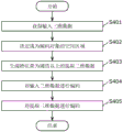
Fig. 53 is a flowchart of the three-dimensional data encoding process according to embodiment 8.
Fig. 54 is a flowchart of the three-dimensional data decoding process according to embodiment 8.
Fig. 55 schematically shows an operation of a modification of the encoding type switching process according to embodiment 8.
Fig. 56 schematically shows an operation of a modification of the encoding type switching process according to embodiment 8.
Fig. 57 schematically shows an operation of a modification of the encoding type switching process according to embodiment 8.
Fig. 58 schematically shows the operation of a modification of the difference value calculation process according to embodiment 8.
Fig. 59 schematically shows the operation of a modification of the difference value calculation process according to embodiment 8.
Fig. 60 schematically shows the operation of a modification of the difference value calculation process according to embodiment 8.
Fig. 61 schematically shows the operation of a modification of the difference value calculation process according to embodiment 8.
Fig. 62 shows an example of syntax of the volume of embodiment 8.
Fig. 63 is a diagram showing an example of a tree structure according to embodiment 9.
Fig. 64 is a diagram showing an example of the number of valid leaf nodes included in each branch according to embodiment 9.
Fig. 65 is a diagram showing an application example of the coding scheme according to embodiment 9.
Fig. 66 is a diagram showing an example of dense branched regions according to embodiment 9.
Fig. 67 is a diagram showing an example of dense three-dimensional point groups according to embodiment 9.
Fig. 68 is a diagram showing an example of a sparse three-dimensional point group according to embodiment 9.
Fig. 69 is a flowchart of the encoding process according to embodiment 9.
Fig. 70 is a flowchart of the decoding process according to embodiment 9.
Fig. 71 is a flowchart of the encoding process according to embodiment 9.
Fig. 72 is a flowchart of the decoding process according to embodiment 9.
Fig. 73 is a flowchart of the encoding process according to embodiment 9.
Fig. 74 is a flowchart of the decoding process according to embodiment 9.
Fig. 75 is a flowchart showing the three-dimensional point separation process according to embodiment 9.
Fig. 76 shows an example of the syntax according to embodiment 9.
Fig. 77 is a diagram showing an example of dense branching according to embodiment 9.
Fig. 78 is a diagram showing an example of sparse branches according to embodiment 9.
Fig. 79 is a flowchart of an encoding process according to a modification of embodiment 9.
Fig. 80 is a flowchart of a decoding process according to a modification of embodiment 9.
Fig. 81 is a flowchart of a three-dimensional point separation process according to a modification of embodiment 9.
Fig. 82 is a diagram showing a sentence law example relating to a modification of embodiment 9.
Fig. 83 is a flowchart of the encoding process according to embodiment 9.
Fig. 84 is a flowchart of the decoding process according to embodiment 9.
Fig. 85 is a diagram showing a reference relationship in the octree structure according to embodiment 10.
Fig. 86 is a diagram showing a reference relationship in a spatial region according to embodiment 10.
Fig. 87 is a diagram showing a reference relationship in a spatial region in modification 1 of embodiment 10.
Fig. 88 is a diagram showing a syntax example of header information according to modification 1 of embodiment 10.
Fig. 89 is a diagram showing a sentence example of header information according to modification 1 of embodiment 10.
Fig. 90 is a diagram showing an example of an adjacent reference node according to modification 2 of embodiment 10.
Fig. 91 is a diagram showing an example of a target node and an adjacent node in modification 2 of embodiment 10.
Fig. 92 is a diagram of a reference relationship in the octree structure according to modification 3 of embodiment 10.
Fig. 93 is a diagram showing a reference relationship in a spatial region in modification 3 of embodiment 10.
Fig. 94 is a diagram showing an example of a tree structure according to embodiment 11.
Fig. 95 is a diagram showing an example of the sub three-dimensional point group according to embodiment 11.
Fig. 96 is a diagram showing an example of the sub three-dimensional point group according to embodiment 11.
Fig. 97 is a diagram showing an example of the structure of a bit stream according to embodiment 11.
Fig. 98 is a diagram showing an example of a tree structure according to embodiment 11.
Fig. 99 is a diagram for explaining the all-parallel encoding according to embodiment 11, and shows an example of a tree structure.
Fig. 100 is a diagram showing spatially sub three-dimensional point groups subjected to parallel processing in embodiment 11.
Fig. 101 is a diagram showing an example of the configuration of a bit stream according to embodiment 11.
Fig. 102 is a diagram for explaining parallel decoding processing according to embodiment 11.
Fig. 103 is a diagram schematically showing a flow of the all-parallel encoding process according to embodiment 11.
Fig. 104 is a diagram schematically showing the flow of the all-parallel decoding process according to embodiment 11.
Fig. 105 is a diagram for explaining progressive parallel coding according to embodiment 11, and shows an example of a tree structure.
Fig. 106 is a diagram showing the operation of the core in the progressive parallel coding according to embodiment 11.
Fig. 107 is a diagram schematically showing the flow of progressive parallel encoding processing according to embodiment 11.
Fig. 108 is a flowchart of the three-dimensional data encoding process according to embodiment 11.
Fig. 109 is a flowchart of the three-dimensional data decoding process according to embodiment 11.
Fig. 110 is a diagram schematically showing the operation of the car access bit stream according to embodiment 12.
Fig. 111 is a diagram showing an example of tile division according to embodiment 12.
Fig. 112 is a diagram showing an example of tile division according to embodiment 12.
Fig. 113 is a diagram showing an example of tile division according to embodiment 12.
Fig. 114 is a diagram showing an example of tile division in the tree structure according to embodiment 12.
Fig. 115 is a diagram showing an example of three-dimensional tile division according to embodiment 12.
Fig. 116 is a view showing tiles read when the automobile according to embodiment 12 is moving.
Fig. 117 is a diagram showing a configuration example of a system according to embodiment 12.
Fig. 118 is a diagram showing an example of the area of a tile obtained by the automobile of embodiment 12.
Fig. 119 is a diagram showing an example of the area of a tile obtained by the automobile of embodiment 12.
Fig. 120 is a diagram showing an example of three-dimensional data according to embodiment 12.
Fig. 121 is a diagram showing an example of slice data according to embodiment 12.
Fig. 122 is a diagram showing an example of slice data according to embodiment 12.
Fig. 123 is a diagram showing an example of slice data according to embodiment 12.
Fig. 124 is a diagram showing an example of a tile according to embodiment 12.
Fig. 125 is a diagram showing an example of tiles in an octree according to embodiment 12.
Fig. 126 is a diagram showing an example of a bit stream according to embodiment 12.
Fig. 127 is a diagram showing an example of a tile table according to embodiment 12.
Fig. 128 is a diagram showing an example of a tile table according to embodiment 12.
Fig. 129 is a diagram showing an example of a tile table according to embodiment 12.
Fig. 130 is a diagram showing an example of a tile table according to embodiment 12.
Fig. 131 is a flowchart of the three-dimensional data encoding process according to embodiment 12.
Fig. 132 is a flowchart of the three-dimensional data decoding process according to embodiment 12.
Fig. 133 is a block diagram of a three-dimensional data encoding device according to embodiment 12.
Fig. 134 is a block diagram of a three-dimensional data decoding device according to embodiment 12.
Fig. 135 is a flowchart of the three-dimensional data encoding process according to embodiment 12.
Fig. 136 is a flowchart of the three-dimensional data decoding process according to embodiment 12.
Fig. 137 is a diagram showing the memory, required actual time, current decoding time, and distance in the case where no slice or tile division is performed and in the case where the slice or tile division is performed according to embodiment 13.
Fig. 138 is a diagram showing an example of tile or slice division according to embodiment 13.
Fig. 139 is a diagram showing an example of a technique for classifying the number of counts of octree division according to embodiment 13.
Fig. 140 is a diagram showing an example of tile or slice division according to embodiment 13.
Fig. 141 is a diagram showing an example of the structure of a bit stream according to embodiment 13.
Fig. 142 is a diagram showing an example of the structure of the SEI in embodiment 13.
Fig. 143 is a diagram showing an example of the syntax of SEI in embodiment 13.
Fig. 144 is a diagram showing a configuration example of a three-dimensional data decoding device according to embodiment 13.
Fig. 145 is a diagram for explaining the work of obtaining data of a tile or slice in embodiment 13.
Fig. 146 is a diagram for explaining the work of obtaining data of tiles or slices according to embodiment 13.
Fig. 147 is a diagram showing the test operation of SEI in embodiment 13.
Fig. 148 is a diagram showing the test operation of the SEI in embodiment 13.
Fig. 149 is a flowchart of the three-dimensional data encoding process according to embodiment 13.
Fig. 150 is a flowchart of the three-dimensional data decoding process according to embodiment 13.
Fig. 151 is a block diagram of a three-dimensional data encoding device according to embodiment 13.
Fig. 152 is a block diagram of a three-dimensional data decoding device according to embodiment 13.
Fig. 153 is a flowchart of three-dimensional data encoding processing according to embodiment 13.
Fig. 154 is a flowchart of the three-dimensional data decoding process according to embodiment 13.
Detailed Description
A three-dimensional data encoding method according to an aspect of the present disclosure generates a bitstream including a plurality of encoded data corresponding to a plurality of subspaces by encoding the plurality of subspaces included in an object space including a plurality of three-dimensional points, stores a list of information of the plurality of subspaces associated with a plurality of identifiers assigned to the plurality of subspaces in 1 st control information common to the plurality of encoded data included in the bitstream, and stores an identifier assigned to the subspace corresponding to the encoded data in a header of each of the plurality of encoded data.
Thus, when decoding a bit stream generated by the three-dimensional data encoding method, the three-dimensional data decoding device can obtain desired encoded data by referring to a list of information of a plurality of subspaces corresponding to a plurality of identifiers stored in the 1 st control information and an identifier stored in a header of each of the plurality of encoded data. Therefore, the processing amount of the three-dimensional data decoding device can be reduced.
For example, the 1 st control information may be arranged before the plurality of encoded data in the bitstream.
For example, the list may include position information of the plurality of subspaces.
For example, the list may include size information of the plurality of subspaces.
For example, the three-dimensional data encoding method may convert the 1 st control information into the 2 nd control information in a protocol of a system to which the bitstream is transmitted.
Thus, the three-dimensional data encoding method can convert control information according to the protocol of the system to which the bit stream is transmitted.
For example, the 2 nd control information may be a table used for random access in the protocol.
For example, the 2 nd control information may be an mdat box (media data box) or a track box (track box) in the ISOBMFF.
A three-dimensional data decoding method according to an aspect of the present disclosure decodes a bitstream that is obtained by encoding a plurality of subspaces included in a target space including a plurality of three-dimensional points and that includes a plurality of encoded data corresponding to the plurality of subspaces, determines a subspace to be decoded of the plurality of subspaces in decoding the bitstream, and obtains encoded data of the subspace to be decoded using a list of information of the plurality of subspaces associated with a plurality of identifiers included in 1 st control information that is common to the plurality of encoded data and included in a header of each of the plurality of encoded data and an identifier allocated to the subspace corresponding to the encoded data.
Thus, the three-dimensional data decoding method can obtain desired encoded data by referring to a list of information of a plurality of subspaces associated with a plurality of identifiers stored in the 1 st control information and the identifiers stored in the headers of the plurality of encoded data. Therefore, the processing amount of the three-dimensional data decoding device can be reduced.
For example, the 1 st control information may be arranged before the plurality of encoded data in the bitstream.
For example, the list may include position information of the plurality of subspaces.
For example, the list may include size information of the plurality of subspaces.
A three-dimensional data encoding device according to an aspect of the present disclosure is a three-dimensional data encoding device that encodes a plurality of three-dimensional points having attribute information, and includes a processor that generates a bitstream including a plurality of encoded data corresponding to the plurality of subspaces by encoding a plurality of subspaces included in a target space including the plurality of three-dimensional points using the memory, wherein in the generation of the bitstream, a list of information of the plurality of subspaces associated with a plurality of identifiers assigned to the plurality of subspaces is stored in 1 st control information common to the plurality of encoded data included in the bitstream, and an identifier assigned to the subspace corresponding to the encoded data is stored in a header of each of the plurality of encoded data.
Thus, the three-dimensional data decoding device can obtain desired encoded data by referring to the list of information of the plurality of subspaces corresponding to the plurality of identifiers stored in the 1 st control information and the identifier stored in the header of each of the plurality of encoded data when decoding the bit stream generated by the three-dimensional data encoding device. Therefore, the processing amount of the three-dimensional data decoding device can be reduced.
A three-dimensional data decoding device according to an aspect of the present disclosure is a three-dimensional data decoding device that decodes a plurality of three-dimensional points having attribute information, and includes a processor and a memory, the processor decoding a bitstream that is obtained by encoding a plurality of subspaces included in a target space including the plurality of three-dimensional points and includes a plurality of encoded data corresponding to the plurality of subspaces, the bitstream being decoded by determining a subspace to be decoded among the plurality of subspaces, using a list of information of the plurality of subspaces that is included in 1 st control information that is common to the plurality of encoded data and that is associated with a plurality of identifiers assigned to the plurality of subspaces and an identifier assigned to the subspace corresponding to the encoded data and included in a header of each of the plurality of encoded data, the list being included in 1 st control information that is common to the bitstream, obtaining encoded data of a subspace of the decoding object.
Thus, the three-dimensional data decoding device can obtain desired encoded data by referring to a list of information of a plurality of subspaces associated with a plurality of identifiers stored in the 1 st control information and the identifier stored in the header of each of the plurality of encoded data. Therefore, the processing amount of the three-dimensional data decoding device can be reduced.
These general and specific aspects can be realized by a system, a method, an integrated circuit, a computer program, or a computer-readable recording medium such as a CD-ROM, and can be realized by any combination of a system, a method, an integrated circuit, a computer program, and a recording medium.
The embodiments are specifically described below with reference to the drawings. In addition, the embodiments to be described below are each a specific example showing the present disclosure. The numerical values, shapes, materials, components, arrangement positions and connection forms of the components, steps, order of the steps, and the like shown in the following embodiments are merely examples, and the present disclosure is not limited thereto. Moreover, among the components of the following embodiments, components that are not described in the technical means illustrating the highest concept will be described as arbitrary components.
(embodiment mode 1)
First, a data structure of the encoded three-dimensional data (hereinafter also referred to as encoded data) according to the present embodiment will be described. Fig. 1 shows a configuration of encoded three-dimensional data according to the present embodiment.
In the present embodiment, the three-dimensional space is divided into Spaces (SPC) corresponding to pictures in encoding of moving images, and three-dimensional data is encoded in units of spaces. The space is further divided into Volumes (VLM) corresponding to macroblocks in moving image coding, and prediction and conversion are performed in units of VLM. The volume includes a minimum unit, i.e., a plurality of Voxels (VXL), corresponding to the location coordinates. The prediction is to generate predicted three-dimensional data similar to the processing unit to be processed with reference to another processing unit, and encode a difference between the predicted three-dimensional data and the processing unit to be processed, as in the prediction performed on the two-dimensional image. The prediction includes not only spatial prediction in which other prediction units at the same time are referred to, but also temporal prediction in which prediction units at different times are referred to.
For example, when encoding a three-dimensional space represented by point cloud data such as point cloud, a three-dimensional data encoding device (hereinafter also referred to as an encoding device) collectively encodes each point of a point cloud or a plurality of points included in a voxel, according to the size of the voxel. When the voxels are subdivided, the three-dimensional shape of the point group can be expressed with high accuracy, and when the size of the voxels is increased, the three-dimensional shape of the point group can be expressed roughly.
Although the following description will be given by taking a case where three-dimensional data is point cloud as an example, the three-dimensional data is not limited to the point cloud, and may be any form of three-dimensional data.
Also, hierarchically structured voxels can be utilized. In this case, in the n-th order, whether or not there is a sample point in the n-1 th order or lower (lower layer of the n-th order) may be sequentially shown. For example, when only the n-th order layer is decoded, if a sample point exists in a level of n-1 th or lower, the decoding can be performed assuming that a sample point exists in the center of a voxel in the n-th order layer.
The encoding device obtains the point cloud data by a distance sensor, a stereo camera, a monocular camera, a gyroscope, an inertial sensor, or the like.
As in the case of encoding of moving images, the space is classified into at least any one of the following 3 prediction structures: an intra space (I-SPC) capable of being decoded separately, a prediction space (P-SPC) capable of being referred to only in one direction, and a bi-directional space (B-SPC) capable of being referred to in two directions. The space has two kinds of time information, i.e., decoding time and display time.
As shown in fig. 1, a processing unit including a plurality Of spaces includes GOS (Group Of Space: Space Group) which is a random access unit. Further, as a processing unit including a plurality of GOS, there is a world space (WLD).
The spatial region occupied by the world space is associated with an absolute position on the earth by GPS, latitude and longitude information, and the like. The position information is stored as meta information. In addition, the meta information may be included in the encoded data or may be transmitted separately from the encoded data.
In addition, all SPCs may be adjacent in three dimensions within a GOS, or SPCs that are not adjacent in three dimensions to other SPCs may be present.
Hereinafter, the processing such as encoding, decoding, or reference corresponding to the three-dimensional data included in the processing unit such as GOS, SPC, or VLM will also be simply referred to as encoding, decoding, or reference for the processing unit. The three-dimensional data included in the processing unit includes at least one set of a spatial position such as a three-dimensional coordinate and a characteristic value such as color information.
Next, the structure of prediction of SPC in GOS will be described. Although a plurality of SPCs in the same GOS or a plurality of VLMs in the same SPC occupy different spaces, they have the same time information (decoding time and display time).
And, in GOS, SPC that is first in decoding order is I-SPC. Also, there are two types of GOS, closed GOS and open GOS. The closed GOS is a GOS for which all SPCs in the GOS can be decoded when decoding is started from the beginning I-SPC. In the open GOS, a part of SPC earlier than the display time of the first I-SPC in a GOS refers to a different GOS, and decoding can be performed only in the GOS.
In addition, in coded data such as map information, WLD may be decoded from a direction opposite to the coding order, and if there is a dependency between GOS, it is difficult to perform reverse reproduction. Therefore, in this case, closed GOS is basically employed.
The GOS has a layer structure in the height direction, and encoding or decoding is performed sequentially from the SPC of the lower layer.
Fig. 2 shows an example of a prediction structure between SPCs belonging to a layer of the lowermost layer of the GOS. Fig. 3 shows an example of the inter-layer prediction structure.
There is more than one I-SPC in a GOS. Although there are objects such as a person, an animal, an automobile, a bicycle, a signal light, and a building which is a landmark on land in the three-dimensional space, it is effective to encode an object having a small size as I-SPC. For example, when decoding GOS at a low throughput or a high speed, a three-dimensional data decoding device (hereinafter also referred to as a decoding device) decodes only I-SPC in GOS.
The encoding device can switch the encoding interval or the frequency of occurrence of the I-SPC according to the degree of density of the objects in the WLD.
In the configuration shown in fig. 3, the encoding device or the decoding device sequentially performs encoding or decoding for a plurality of layers from the lower layer (layer 1). This makes it possible to increase the priority of data near the ground, which has a large amount of information, for example, for a vehicle that is traveling automatically.
In coded data used by a drone (drone), etc., the coding and decoding can be performed sequentially from SPC of a layer above in the height direction within GOS.
The encoding device or the decoding device may encode or decode a plurality of layers so that the decoding device can roughly grasp GOS and gradually increase the resolution. For example, the encoding apparatus or the decoding apparatus may perform encoding or decoding in the order of layers 3, 8, 1, and 9 … ….
Next, a method of associating a static object with a dynamic object will be described.
In the three-dimensional space, there are static objects or scenes such as buildings and roads (hereinafter collectively referred to as static objects) and dynamic objects such as vehicles and people (hereinafter referred to as dynamic objects). The detection of the object may be additionally performed by extracting feature points from data of the point cloud, or a captured image such as a stereo camera. Here, an example of a method of encoding a dynamic object will be described.
The method 1 is a method of encoding without distinguishing a static object from a dynamic object. The 2 nd method is a method of distinguishing a static object from a dynamic object by identification information.
For example, GOS is used as a recognition unit. In this case, the GOS including SPC constituting the static object and the GOS including SPC constituting the dynamic object are distinguished from each other by coded data or by identification information stored separately from the coded data.
Alternatively, SPC is used as the identification unit. In this case, the SPC including only the VLMs constituting the static object and the SPC including the VLMs constituting the dynamic object are distinguished from each other by the above-described identification information.
Alternatively, VLM or VXL can be used as the recognition unit. In this case, the VLM or VXL including the static object and the VLM or VXL including the dynamic object are distinguished from each other by the identification information.
The encoding device may encode the dynamic object as one or more VLMs or SPCs, and encode the VLM or SPC including the static object and the SPC including the dynamic object as GOS different from each other. When the size of the GOS is variable according to the size of the moving object, the encoding device stores the size of the GOS as meta information.
The encoding device encodes the static object and the dynamic object independently of each other, and can superimpose the dynamic object on the world space formed by the static object. In this case, the dynamic object is composed of one or more SPCs, and each SPC corresponds to one or more SPCs constituting the static object on which the SPC is superimposed. In addition, dynamic objects may not be represented by SPC, and may be represented by more than one VLM or VXL.
Also, the encoding device may encode the static object and the dynamic object as different streams from each other.
The encoding device may generate GOS including one or more SPCs constituting the dynamic object. The encoding device may set the GOS (GOS _ M) including the dynamic object and the GOS including the static object corresponding to the spatial region of GOS _ M to have the same size (occupy the same spatial region). In this way, the overlapping process can be performed in units of GOS.
The P-SPC or B-SPC constituting the dynamic object may refer to SPC included in a different GOS that has been encoded. In the case where the position of a dynamic object changes with time and the same dynamic object is encoded as GOS at different times, reference across GOS is effective from the viewpoint of compression rate.
Further, the method 1 and the method 2 may be switched according to the use of the encoded data. For example, when the encoded three-dimensional data is applied as a map, the encoding apparatus adopts the method 2 because it is desired to separate the encoded three-dimensional data from the dynamic object. In addition, when encoding three-dimensional data of a motion such as a concert or a sport, the encoding device adopts the method 1 if it is not necessary to separate a dynamic object.
The decoding time and the display time of GOS or SPC can be stored in the encoded data or stored as meta information. Also, the time information of the static objects may all be the same. In this case, the actual decoding time and display time may be determined by the decoding apparatus. Alternatively, different values may be assigned to the decoding time for each GOS or SPC, and the same value may be assigned to all the display times. As shown in a decoder mode in moving picture coding such as hrd (predictive decoder) in HEVC, a decoder has a buffer of a predetermined size, and can introduce a model that can be decoded without being destroyed if a bit stream is read at a predetermined bit rate according to decoding time.
Next, the arrangement of GOS in the world space will be described. The coordinates of a three-dimensional space in the world space are expressed by 3 coordinate axes (x-axis, y-axis, z-axis) orthogonal to each other. By setting a predetermined rule in the coding order of GOS, spatially adjacent GOS can be coded continuously within coded data. For example, in the example shown in fig. 4, GOS in the xz plane is successively encoded. After the encoding of all GOS in one xz plane is completed, the y-axis value is updated. That is, as the encoding is continued, the world space extends in the y-axis direction. The index number of the GOS is set to the coding order.
Here, the three-dimensional space of the world space corresponds to a GPS, or a geographical absolute coordinate such as a latitude and a longitude. Alternatively, the three-dimensional space may be represented by a relative position with respect to a preset reference position. Directions of an x-axis, a y-axis, and a z-axis of a three-dimensional space are expressed as direction vectors determined based on latitude, longitude, and the like, and the direction vectors are stored as meta information together with encoded data.
The GOS is set to a fixed size, and the encoding apparatus stores the size as meta information. The GOS size can be switched according to whether it is, for example, urban, indoor, outdoor, or the like. That is, the size of GOS can be switched according to the quantity or the property of the object having the value as information. Alternatively, the encoding device may switch the size of GOS and the interval of I-SPC in GOS appropriately in accordance with the density of the object or the like in the same world space. For example, the encoding apparatus sets the GOS size to be small and sets the interval of I-SPC in the GOS to be short as the density of the target is higher.
In the example of fig. 5, in the area from the 3 rd to the 10 th GOS, since the density of objects is high, the GOS is subdivided to realize random access with a fine granularity. And, GOS from 7 th to 10 th exist on the back side of GOS from 3 rd to 6 th, respectively.
Next, the configuration and the flow of operation of the three-dimensional data encoding device according to the present embodiment will be described. Fig. 6 is a block diagram of the three-dimensional data encoding device 100 according to the present embodiment. Fig. 7 is a flowchart showing an example of the operation of the three-dimensional data encoding device 100.
The three-dimensional data encoding device 100 shown in fig. 6 encodes three-dimensional data 111 to generate encoded three-dimensional data 112. The three-dimensional data encoding device 100 includes: an obtaining unit 101, an encoding region determining unit 102, a dividing unit 103, and an encoding unit 104.
As shown in fig. 7, first, the obtaining unit 101 obtains three-dimensional data 111 as point cloud data (S101).
Next, the encoding region determining unit 102 determines a region to be encoded from among the spatial regions corresponding to the obtained point cloud data (S102). For example, the encoding region determining unit 102 determines a spatial region around the position of the user or the vehicle as the region to be encoded.
Next, the dividing unit 103 divides the point cloud data included in the region to be encoded into each processing unit. Here, the processing units include GOS, SPC, and the like. The region to be encoded corresponds to, for example, the above-described world space. Specifically, the dividing unit 103 divides the point cloud data into processing units according to the preset GOS size, the presence or absence of a moving object, or the size (S103). Then, the divider 103 determines the start position of the SPC that becomes the head in the coding order for each GOS.
Next, the encoding unit 104 sequentially encodes a plurality of SPCs in each GOS to generate encoded three-dimensional data 112 (S104).
Here, although an example of encoding each GOS after dividing the area to be encoded into GOS and SPC is shown, the order of processing is not limited to the above. For example, after the configuration of one GOS is determined, the GOS may be encoded, and thereafter, the order of the configuration of the GOS and the like may be determined.
In this way, the three-dimensional data encoding device 100 encodes the three-dimensional data 111 to generate the encoded three-dimensional data 112. Specifically, the three-dimensional data encoding device 100 divides the three-dimensional data into random access units, that is, into 1 st processing unit (GOS) corresponding to the three-dimensional coordinates, divides the 1 st processing unit (GOS) into a plurality of 2 nd processing units (SPC), and divides the 2 nd processing unit (SPC) into a plurality of 3 rd processing units (VLM). The 3 rd processing unit (VLM) includes one or more Voxels (VXL), and the Voxel (VXL) is a minimum unit corresponding to the position information.
Next, the three-dimensional data encoding device 100 generates encoded three-dimensional data 112 by encoding each of the plurality of processing units 1 (GOS). Specifically, the three-dimensional data encoding device 100 encodes each of the plurality of processing units 2 (SPC) in each processing unit 1 (GOS). The three-dimensional data encoding device 100 encodes each of the plurality of processing units 3 (VLMs) in each processing unit 2 (SPC).
For example, when the processing target 1 st process unit (GOS) is a closed GOS, the three-dimensional data encoding device 100 performs encoding with reference to the other processing unit 2 (SPC) included in the processing target 1 st process unit (GOS) with respect to the processing target 2 nd process unit (SPC) included in the processing target 1 st process unit (GOS). That is, the three-dimensional data encoding device 100 does not refer to the 2 nd processing unit (SPC) included in the 1 st processing unit (GOS) different from the 1 st processing unit (GOS) to be processed.
On the other hand, when the 1 st process unit (GOS) is an open GOS, the 2 nd process unit (SPC) included in the 1 st process unit (GOS) is encoded by referring to the other 2 nd process unit (SPC) included in the 1 st process unit (GOS) or the 2 nd process unit (SPC) included in the 1 st process unit (GOS) different from the 1 st process unit (GOS).
The three-dimensional data encoding device 100 selects one of the 1 st type (I-SPC) that does not refer to the other 2 nd process unit (SPC), the 2 nd type (P-SPC) that refers to the other one 2 nd process unit (SPC), and the 3 rd type that refers to the other two 2 nd process units (SPC) as the type of the 2 nd process unit (SPC) to be processed, and encodes the 2 nd process unit (SPC) to be processed according to the selected type.
Next, the configuration and the flow of operation of the three-dimensional data decoding device according to the present embodiment will be described. Fig. 8 is a block diagram of the three-dimensional data decoding device 200 according to the present embodiment. Fig. 9 is a flowchart showing an example of the operation of the three-dimensional data decoding apparatus 200.
The three-dimensional data decoding device 200 shown in fig. 8 generates decoded three-dimensional data 212 by decoding the encoded three-dimensional data 211. Here, the encoded three-dimensional data 211 is, for example, the encoded three-dimensional data 112 generated by the three-dimensional data encoding device 100. The three-dimensional data decoding device 200 includes: an obtaining unit 201, a decoding start GOS determining unit 202, a decoding SPC determining unit 203, and a decoding unit 204.
First, the obtaining unit 201 obtains encoded three-dimensional data 211 (S201). Next, the decoding start GOS determination unit 202 determines a GOS to be decoded (S202). Specifically, the decoding start GOS determination unit 202 refers to the meta information stored in the encoded three-dimensional data 211 or in the encoded three-dimensional data, and determines a GOS including a spatial position and an object to start decoding, or an SPC corresponding to a time, as a GOS to be decoded.
Next, the decoding SPC determining unit 203 determines the type of SPC to be decoded in the GOS (I, P, B) (S203). For example, the decoding SPC determination unit 203 determines whether (1) only I-SPC is decoded, (2) I-SPC and P-SPC are decoded, and (3) all types are decoded. In addition, when the type of SPC to be decoded is previously defined such as decoding all SPCs, this step may not be performed.
Next, the decoding unit 204 obtains the SPC that is at the head in the decoding order (same as the encoding order) in the GOS, obtains the encoded data of the head SPC from the address position at the start in the encoded three-dimensional data 211, and decodes each SPC in sequence from the head SPC (S204). The address location is stored in meta information or the like.
Thus, the three-dimensional data decoding device 200 decodes the decoded three-dimensional data 212. Specifically, the three-dimensional data decoding device 200 decodes each of the encoded three-dimensional data 211 of the 1 st processing unit (GOS) corresponding to the three-dimensional coordinates, and generates the decoded three-dimensional data 212 of the 1 st processing unit (GOS) which is a random access unit. More specifically, the three-dimensional data decoding apparatus 200 decodes each of a plurality of 2 nd processing units (SPC) in each 1 st processing unit (GOS). The three-dimensional data decoding device 200 decodes each of the plurality of 3 rd processing units (VLMs) in each of the 2 nd processing units (SPC).
The meta information for random access will be described below. The meta information is generated by the three-dimensional data encoding apparatus 100 and is included in the encoded three-dimensional data 112 (211).
In conventional random access of a two-dimensional moving picture, decoding is started from the head frame of a random access unit in the vicinity of a predetermined time. However, in world space, random access to (coordinates, objects, etc.) is also contemplated in addition to time of day.
Therefore, in order to realize random access to at least 3 elements of coordinates, objects, and time, a table is prepared in which each element is associated with the index number of the GOS. The index number of the GOS is associated with the address of the I-SPC that is the head of the GOS. Fig. 10 shows an example of a table contained in meta information. In addition, all the tables shown in fig. 10 need not be used, and at least one table may be used.
Hereinafter, random access starting from coordinates will be described as an example. When accessing the coordinates (x2, y2, z2), first, the coordinates-GOS table is referred to, and it is known that the 2 nd GOS includes the location having the coordinates (x2, y2, z 2). Next, referring to the GOS address table, since it is known that the address of the I-SPC headed in the 2 nd GOS is addr (2), the decoding unit 204 acquires data from the address and starts decoding.
The address may be an address in a logical format, or may be a physical address of the HDD or the memory. Instead of the address, information for specifying the file segment may be used. For example, a file segment is a unit obtained by segmenting one or more GOS or the like.
In addition, when the target object spans a plurality of GOSs, the target GOS table may indicate the GOS to which the plurality of objects belong. If the plurality of GOS are closed GOS, the encoding device and the decoding device can perform encoding or decoding in parallel. In addition, if the plurality of GOSs are open GOSs, the plurality of GOSs are mutually referred to each other, thereby further improving the compression efficiency.
Examples of the target include a human being, an animal, an automobile, a bicycle, a signal light, and a building which serves as a landmark on land. For example, the three-dimensional data encoding device 100 can extract a feature point unique to an object from a three-dimensional point cloud or the like at the time of world space encoding, detect the object from the feature point, and set the detected object as a random access point.
In this way, the three-dimensional data encoding device 100 generates 1 st information indicating a plurality of 1 st processing units (GOS) and three-dimensional coordinates corresponding to each of the plurality of 1 st processing units (GOS). And, the encoded three-dimensional data 112(211) includes the 1 st information. The 1 st information further indicates at least one of an object, time, and data storage destination corresponding to each of the 1 st processing units (GOS).
The three-dimensional data decoding device 200 obtains the 1 st information from the encoded three-dimensional data 211, specifies the encoded three-dimensional data 211 of the 1 st processing unit corresponding to the specified three-dimensional coordinates, object, or time using the 1 st information, and decodes the encoded three-dimensional data 211.
Other examples of meta information are explained below. The three-dimensional data encoding device 100 may generate and store the following meta information in addition to the meta information for random access. The three-dimensional data decoding device 200 may use the meta information in decoding.
When the three-dimensional data is used as map information, a profile (profile) is specified according to the application, and information indicating the profile may be included in the meta information. For example, urban or suburban oriented profiles are specified, or flyer oriented profiles are specified, and the world space, the maximum or minimum size of the SPC or VLM, respectively, etc. are defined. For example, in a grade oriented to urban areas, more detailed information is required than in suburban areas, and therefore the minimum size of the VLM is set to be small.
The meta information may also include a tag value showing the kind of the object. The tag value corresponds to VLM, SPC, or GOS constituting the object. The tag value may be set according to the type of the object, for example, the tag value "0" indicates "person", the tag value "1" indicates "car", and the tag value "2" indicates "traffic light". Alternatively, when the type of object is difficult or unnecessary to be determined, a tag value indicating a property such as a size, a dynamic object, or a static object may be used.
The meta information may include information showing a range of a spatial region occupied by the world space.
The meta information may store the size of SPC or VXL as header information common to a plurality of SPCs such as SPC in GOS or the entire stream of encoded data.
The meta information may include identification information such as a distance sensor or a camera used for generating the point cloud, or information indicating the position accuracy of the point group in the point cloud.
Also, the meta information may include information showing whether the world space is composed of only static objects or contains dynamic objects.
A modified example of the present embodiment will be described below.
The encoding apparatus or the decoding apparatus may encode or decode two or more SPCs or GOS different from each other in parallel. The GOS to be encoded or decoded in parallel can be determined based on meta information indicating the spatial position of the GOS, and the like.
In the case where the three-dimensional data is used as a space map when a vehicle, a flying object, or the like moves, or such a space map is generated, the encoding device or the decoding device may encode or decode GOS or SPC included in a space determined based on GPS, route information, zoom ratio, or the like.
The decoding device may decode sequentially from a space near its own position or a travel route. The encoding device or the decoding device may perform encoding or decoding by setting the priority of a space far from its own position or a travel path to be lower than the priority of a space near thereto. Here, the priority is lowered by lowering the processing order, lowering the resolution (post-filtering processing), lowering the image quality (improving the encoding efficiency, for example, increasing the quantization step size), or the like.
When decoding encoded data that is hierarchically encoded in a space, the decoding device may decode only a lower layer.
The decoding device may start decoding from the lower layer in accordance with the zoom ratio or the use of the map.
In applications such as self-position estimation and object recognition performed during automatic traveling of a vehicle or a robot, the encoding device or the decoding device may encode or decode a region other than a region within a predetermined height from a road surface (a region to be recognized) by reducing the resolution.
The encoding device may encode the point clouds representing the spatial shapes indoors and outdoors independently. For example, by separating the GOS representing indoors (indoor GOS) from the GOS representing outdoors (outdoor GOS), the decoding apparatus can select a GOS to be decoded according to the viewpoint position when using the encoded data.
The encoding device may perform encoding by making the indoor GOS and the outdoor GOS having the close coordinates adjacent to each other in the encoded stream. For example, the encoding device associates identifiers of both devices, and stores information indicating that the corresponding identifiers are established in the encoded stream or in the meta-information stored separately. Accordingly, the decoding apparatus can identify the indoor GOS and the outdoor GOS to which the coordinates are close, with reference to the information in the meta information.
The encoding device may switch the size of GOS or SPC between the indoor GOS and the outdoor GOS. For example, the coding apparatus sets the GOS to be smaller indoors than outdoors. The encoding device may change the accuracy of extracting the feature points from the point cloud, the accuracy of detecting the object, and the like in the indoor GOS and the outdoor GOS.
The encoding device may add information for the decoding device to distinguish and display the dynamic object from the static object to the encoded data. Accordingly, the decoding device can combine the moving object with a red frame, a character for explanation, or the like to represent the moving object. Instead of the dynamic object, the decoding apparatus may be represented by a red frame or a text for description. Also, the decoding apparatus may represent more detailed object categories. For example, a car may use a red frame and a person may use a yellow frame.
The encoding device or the decoding device may determine whether to perform encoding or decoding by using the dynamic object and the static object as different SPC or GOS according to the frequency of appearance of the dynamic object, the ratio of the static object to the dynamic object, or the like. For example, SPC or GOS in which a dynamic object and a static object are mixed is permitted when the frequency of appearance or the ratio of the dynamic object exceeds a threshold value, and SPC or GOS in which a dynamic object and a static object are mixed is not permitted when the frequency of appearance or the ratio of the dynamic object does not exceed a threshold value.
When a moving object is detected not from a point cloud but from two-dimensional image information of a camera, the encoding device may obtain information (a frame, characters, or the like) for identifying the detection result and the object position, and encode the information as a part of three-dimensional encoded data. In this case, the decoding device displays auxiliary information (frames or characters) indicating the dynamic object in a superimposed manner on the decoding result of the static object.
The encoding device may change the density of VXL or VLM according to the complexity of the shape of the static object. For example, the more complex the shape of the static object, the more dense VXL or VLM the encoding device is set. The encoding device may determine a quantization step size or the like for quantizing the spatial position or the color information according to the density of VXL or VLM. For example, the encoding device sets the quantization step size to be smaller as VXL or VLM is denser.
As described above, the encoding device or the decoding device according to the present embodiment performs spatial encoding or decoding in spatial units having coordinate information.
The encoding device and the decoding device perform encoding or decoding in units of volume in space. The volume includes the smallest unit, i.e., voxel, corresponding to the location information.
The encoding device and the decoding device perform encoding or decoding by associating each element including spatial information such as coordinates, objects, and time with a GOP or a table in which each element is associated with another element, and associating arbitrary elements with each other. The decoding device determines the coordinates using the values of the selected elements, specifies a volume, a voxel, or a space from the coordinates, and decodes the space including the volume or the voxel, or the specified space.
The encoding device determines a volume, voxel, or space that can be selected by the element by feature point extraction or object recognition, and encodes the determined volume, voxel, or space as a volume, voxel, or space that can be randomly accessed.
Spaces are divided into three types, namely: I-SPC that can be encoded or decoded with this space unit, P-SPC that is encoded or decoded with reference to any one of the processed spaces, and B-SPC that is encoded or decoded with reference to any two of the processed spaces.
More than one volume corresponds to a static object or a dynamic object. The space containing the static object and the space containing the dynamic object are encoded or decoded as different GOS from each other. That is, the SPC including the static object and the SPC including the dynamic object are assigned to different GOS.
The dynamic objects are encoded or decoded for each object, and correspond to one or more spaces including only static objects. That is, a plurality of dynamic objects are encoded, and the obtained encoded data of the plurality of dynamic objects corresponds to SPC including only static objects.
The encoding device and the decoding device increase the priority of I-SPC in GOS for encoding or decoding. For example, the encoding device performs encoding so as to reduce the degradation of I-SPC (after decoding, the original three-dimensional data can be reproduced more faithfully). And, the decoding means decodes, for example, only the I-SPC.
The encoding device may perform encoding by changing the frequency of using I-SPC according to the degree of hydrophobicity or the number (number) of objects in the world space. That is, the encoding device changes the frequency of selecting I-SPC according to the number of objects included in the three-dimensional data or the degree of density. For example, the encoding device increases the frequency of use of the I space as the density of objects in the world space increases.
The coding apparatus sets a random access point in units of GOS, and stores information indicating a spatial region corresponding to the GOS in header information.
The encoding apparatus adopts a default value as the spatial size of the GOS, for example. The encoding device may change the size of the GOS according to the value (number) or the degree of density of the object or the dynamic object. For example, the encoding apparatus sets the spatial size of GOS to be smaller as the density or number of the objects or dynamic objects increases.
The space or volume includes a feature point group derived from information obtained by a sensor such as a depth sensor, a gyroscope, or a camera. The coordinates of the feature points are set as the center positions of the voxels. Further, by subdividing the voxels, high accuracy of the position information can be achieved.
The feature point group is derived using a plurality of pictures. The plurality of pictures have at least the following two kinds of time information: actual time information, and the same time information (e.g., encoding time used for rate control or the like) in a plurality of pictures corresponding to a space.
And, encoding or decoding is performed in units of GOS including one or more spaces.
The encoding device and the decoding device refer to the space in the processed GOS and predict the P space or the B space in the GOS to be processed.
Alternatively, the encoding apparatus and the decoding apparatus predict the P space or the B space in the GOS to be processed using the processed space in the GOS to be processed without referring to a different GOS.
The encoding device and the decoding device transmit or receive the encoded stream in units of world space including one or more GOS.
The GOS has a layer structure in at least one direction in the world space, and the encoding device and the decoding device perform encoding or decoding from a lower layer. For example, a GOS that can be randomly accessed belongs to the lowest layer. The GOS belonging to the upper layer refers to only GOS belonging to layers lower than the same layer. That is, the GOS is spatially divided in a predetermined direction and includes a plurality of layers each having one or more SPCs. The encoding device and the decoding device perform encoding or decoding on each SPC by referring to the SPC included in the same layer as the SPC or a layer lower than the SPC.
The encoding device and the decoding device successively encode or decode GOS in a world space unit including a plurality of GOS. The encoding device and the decoding device write or read information indicating the order (direction) of encoding or decoding as metadata. That is, the encoded data includes information showing the encoding order of the plurality of GOS.
The encoding device and the decoding device encode or decode two or more different spaces or GOS in parallel.
The encoding device and the decoding device encode or decode spatial information (coordinates, size, and the like) of the space or GOS.
The encoding device and the decoding device encode or decode a space or GOS included in a specific space specified by external information on its own position and/or area size such as GPS, route information, or magnification.
The encoding device or the decoding device performs encoding or decoding by setting the priority of a space far from the encoding device or the decoding device to be lower than that of a space near to the encoding device or the decoding device.
The encoding device sets one direction in the world space according to the magnification or the application, and encodes GOS having a layer structure in the direction. The decoding device preferentially decodes a GOS having a layer structure in one direction of the world space, which has been set according to the magnification or the application, from a lower layer.
The encoding device changes the accuracy of extracting feature points, identifying objects, or changing the size of a spatial region included in indoor and outdoor spaces. However, the encoding device and the decoding device encode or decode the indoor GOS and the outdoor GOS which have close coordinates and are adjacent to each other in the world space, and encode or decode the indoor GOS and the outdoor GOS by associating these identifiers with each other.
(embodiment mode 2)
When the encoded data of the point cloud is used for an actual device or service, it is desirable to transmit and receive necessary information according to the application in order to suppress the network bandwidth. However, since such a function does not exist in the conventional three-dimensional data encoding structure, there is no encoding method therefor.
In the present embodiment, a three-dimensional data encoding method and a three-dimensional data encoding device for providing a function of transmitting and receiving necessary information in encoded data of a three-dimensional point cloud according to an application, and a three-dimensional data decoding method and a three-dimensional data decoding device for decoding the encoded data will be described.
Voxels (VXL) having a certain or more characteristic amount are defined as characteristic voxels (FVXL), and a world space (WLD) composed of FVXL is defined as a sparse world Space (SWLD). Fig. 11 shows a sparse world space and an example of the structure of the world space. In the SWLD include: FGOS, GOS composed of FVXL; FSPC, SPC composed of FVXL; and FVLM, which is a VLM composed of FVXL. The data structures and prediction structures of FGOS, FSPC, and FVLM may be the same as GOS, SPC, and VLM.
The feature value is a feature value representing three-dimensional position information of VXL or visible light information of VXL position, and is particularly a feature value in which a large number of corners, edges, and the like of a three-dimensional object can be detected. Specifically, the feature amount is a three-dimensional feature amount or a visible light feature amount described below, and may be any feature amount as long as the feature amount indicates the position, brightness, color information, or the like of VXL.
As the three-dimensional Feature amount, a SHOT Feature amount (Signature of features of orietations: orientation histogram features), a PFH Feature amount (Point Feature Histograms), or a PPF Feature amount (Point Pair features) is used.
The SHOT feature value is obtained by dividing the periphery of VXL, calculating the inner product of the reference point and the normal vector of the divided region, and performing histogram formation. The SHOT feature quantity has features of high dimension and high feature expression.
The PFH feature value is obtained by selecting a plurality of 2-point groups near VXL, calculating a normal vector and the like from these 2 points, and performing histogram formation. The PFH feature is a histogram feature, and thus is robust against small-amount disturbances and has a feature of high feature expression.
The PPF feature value is a feature value calculated by using a normal vector or the like for VXL at 2 points. In this PPF feature, all VXL is used, and thus, the PPF feature has robustness against shading.
In addition, as the Feature amount of visible light, SIFT (Scale-Invariant Feature Transform), SURF (Speeded Up Robust Features), HOG (Histogram of Oriented Gradients), or the like, which uses information such as luminance gradient information of an image, can be used.
The SWLD is generated by calculating the above feature amount from each VXL in WLD and extracting FVXL. Here, the SWLD may be updated every time the WLD is updated, or may be periodically updated after a certain time elapses, regardless of the update timing of the WLD.
The SWLD may be generated for each feature amount. For example, as shown in SWLD1 based on the SHOT feature value and SWLD2 based on the SIFT feature value, SWLDs may be generated for each feature value and used for different purposes. The calculated characteristic amount of each FVXL may be stored as characteristic amount information in each FVXL.
Next, a method of using the sparse world Space (SWLD) will be described. Since SWLD contains only characteristic voxels (FVXL), the data size is typically small compared to WLDs that include all VXL.
In an application program that achieves a certain purpose using feature values, by using SWLD information instead of WLD, it is possible to suppress the read time from a hard disk and to suppress the bandwidth and transmission time during network transmission. For example, WLD and SWLD are held in advance as map information in a server, and the transmitted map information is switched to WLD or SWLD in accordance with a request from a client, whereby the network bandwidth and the transmission time can be suppressed. Specific examples are shown below.
Fig. 12 and 13 show usage examples of the SWLD and the WLD. As shown in fig. 12, when the client 1 as the in-vehicle device needs map information for its own position determination, the client 1 transmits a request for obtaining map data for its own position estimation to the server (S301). The server transmits the SWLD to the client 1 according to the acquisition demand (S302). The client 1 performs its own position determination using the received SWLD (S303). At this time, the client 1 obtains VXL information around the client 1 by various methods such as a distance meter equidistant sensor, a stereo camera, or a combination of a plurality of monocular cameras, and estimates the own position information from the obtained VXL information and SWLD. Here, the self-position information includes three-dimensional position information, orientation, and the like of the client 1.
As shown in fig. 13, when the client 2 as the in-vehicle device needs map information for the purpose of map drawing such as a three-dimensional map, the client 2 transmits a request for obtaining map data for map drawing to the server (S311). The server sends WLD to the client 2 according to the acquisition demand (S312). The client 2 performs mapping using the received WLD (S313). At this time, the client 2 creates a conceptual image using, for example, an image captured by the client itself using a visible light camera or the like and a WLD obtained from the server, and draws the created image on a screen of a car navigation system or the like.
As described above, the server transmits the SWLD to the client in the application where the characteristic amount of each VXL mainly requires the own position estimation, and transmits the WLD to the client when detailed VXL information is required as in the map drawing. Thus, the map data can be efficiently transmitted and received.
In addition, the client can determine which of the SWLD and WLD is required and request the server for either SWLD or WLD transmission. The server can determine which of the SWLD and WLD should be transmitted according to the status of the client or the network.
Next, a method of switching transmission and reception between the sparse world Space (SWLD) and the world space (WLD) will be described.
The reception of WLD or SWLD can be switched according to the network bandwidth. Fig. 14 shows an example of the operation in this case. For example, when a low-speed network capable of using a network bandwidth in an LTE (Long Term Evolution) environment or the like is used, a client accesses a server via the low-speed network (S321), and obtains SWLD as map information from the server (S322). When a high-speed network having a spare network bandwidth such as a WiFi environment is used, the client accesses the server via the high-speed network (S323), and acquires a WLD from the server (S324). Accordingly, the client can obtain appropriate map information according to the network bandwidth of the client.
Specifically, the client receives SWLD via LTE outdoors and obtains WLD via WiFi when entering indoors such as a facility. Accordingly, the client can obtain more detailed map information indoors.
In this way, the client can request WLD or SWLD from the server according to the band of the network used by itself. Alternatively, the client may transmit information indicating the frequency band of the network used by the client to the server, and the server may transmit appropriate data (WLD or SWLD) to the client in accordance with the information. Alternatively, the server may determine the network bandwidth of the client and send the appropriate data (WLD or SWLD) to the client.
Also, the reception of WLD or SWLD can be switched according to the moving speed. Fig. 15 shows an example of the operation in this case. For example, when the client moves at a high speed (S331), the client receives the SWLD from the server (S332). In addition, when the client moves at a low speed (S333), the client receives WLD from the server (S334). Accordingly, the client can obtain map information according to the speed while suppressing the network bandwidth. Specifically, the client can update the map information at an approximately appropriate speed by receiving the SWLD having a small data amount while the client is traveling on the highway. Further, when the client travels on a general road, more detailed map information can be obtained by receiving the WLD.
In this way, the client can request WLD or SWLD from the server at its own moving speed. Alternatively, the client may transmit information showing its own moving speed to the server, and the server may transmit appropriate data (WLD or SWLD) to the client in accordance with the information. Alternatively, the server may determine the moving speed of the client and send appropriate data (WLD or SWLD) to the client.
Also, the client may obtain the SWLD from the server first, and then obtain the WLD of the important area therein. For example, when obtaining map data, the client first obtains general map information using the SWLD, and then filters an area in which features such as buildings, logos, and people appear in a large amount, and then obtains the WLD of the filtered area. Thus, the client can obtain the detailed information of the required area while suppressing the amount of received data from the server.
The server may create the SWLD for each object from the WLD and the client may receive the SWLD for each application. Accordingly, the network bandwidth can be suppressed. For example, the server recognizes a person or a vehicle from the WLD in advance, and creates a SWLD of the person and a SWLD of the vehicle. The client receives the SWLD of the person when the client wants to obtain the information of the surrounding person, and receives the SWLD of the vehicle when the client wants to obtain the information of the vehicle. The type of SWLD can be distinguished according to information (such as a mark or a type) attached to a head.
Next, the configuration and the flow of operation of the three-dimensional data encoding device (for example, server) according to the present embodiment will be described. Fig. 16 is a block diagram of the three-dimensional data encoding device 400 according to the present embodiment. Fig. 17 is a flowchart of three-dimensional data encoding processing performed by the three-dimensional data encoding device 400.
The three-dimensional data encoding device 400 shown in fig. 16 encodes input three-dimensional data 411 to generate encoded three- dimensional data 413 and 414 as encoded streams. Here, the encoded three-dimensional data 413 is encoded three-dimensional data corresponding to WLD, and the encoded three-dimensional data 414 is encoded three-dimensional data corresponding to SWLD. The three-dimensional data encoding device 400 includes: an obtaining unit 401, an encoding region determining unit 402, an SWLD extracting unit 403, a WLD encoding unit 404, and an SWLD encoding unit 405.
As shown in fig. 17, first, the obtaining unit 401 obtains input three-dimensional data 411 as point cloud data in a three-dimensional space (S401).
Next, the encoding region determining unit 402 determines a spatial region to be encoded based on the spatial region in which the point cloud data exists (S402).
Next, the SWLD extraction unit 403 defines the space region to be encoded as WLD, and calculates the feature amount from each VXL included in WLD. The SWLD extracting unit 403 extracts VXL having a feature value equal to or greater than a predetermined threshold value, defines the extracted VXL as FVXL, and adds the FVXL to the SWLD to generate the extracted three-dimensional data 412 (S403). That is, the extracted three-dimensional data 412 having a feature amount equal to or greater than the threshold value is extracted from the input three-dimensional data 411.
Next, the WLD encoding unit 404 encodes the input three-dimensional data 411 corresponding to the WLD, thereby generating encoded three-dimensional data 413 corresponding to the WLD (S404). At this time, the WLD encoding unit 404 adds information for distinguishing that the encoded three-dimensional data 413 is a stream including the WLD to the head of the encoded three-dimensional data 413.
Then, the SWLD encoding unit 405 encodes the extracted three-dimensional data 412 corresponding to the SWLD, thereby generating encoded three-dimensional data 414 corresponding to the SWLD (S405). At this time, the SWLD encoding unit 405 adds information for distinguishing that the encoded three-dimensional data 414 is a stream including a SWLD to the header of the encoded three-dimensional data 414.
The order of the process of generating the encoded three-dimensional data 413 and the process of generating the encoded three-dimensional data 414 may be reversed. Further, a part or all of the above-described processing may be executed in parallel.
The information assigned to the heads of the encoded three- dimensional data 413 and 414 is defined as a parameter such as "world _ type", for example. When world _ type is 0, the stream is indicated to include WLD, and when world _ type is 1, the stream is indicated to include SWLD. In the case where other more categories are defined, the assigned value may be increased as world _ type ═ 2. Further, a specific flag may be included in one of the encoded three- dimensional data 413 and 414. For example, the encoded three-dimensional data 414 may be given a flag indicating that the stream contains a SWLD. In this case, the decoding device can determine whether the stream includes WLD or SWLD according to the presence or absence of the flag.
Further, the encoding method used when WLD encoding unit 404 encodes WLD may be different from the encoding method used when SWLD encoding unit 405 encodes SWLD.
For example, since the SWLD data is decimated, there is a possibility that correlation with peripheral data becomes lower than WLD. Therefore, in the encoding method for SWLD, inter prediction among intra prediction and inter prediction is prioritized compared to the encoding method for WLD.
In addition, the encoding method for SWLD and the encoding method for WLD may differ in the expression method of the three-dimensional position. For example, the three-dimensional position of FVXL may be expressed by three-dimensional coordinates in FWLD, and the three-dimensional position may be expressed by an octree described later in WLD, and vice versa.
The SWLD encoding unit 405 encodes the SWLD encoded three-dimensional data 414 so that the data size thereof is smaller than the data size of the WLD encoded three-dimensional data 413. For example, as described above, the correlation between data may be reduced in the SWLD compared to the WLD. Accordingly, the encoding efficiency is reduced, and the data size of the encoded three-dimensional data 414 may be larger than the data size of the encoded three-dimensional data 413 of WLD. Therefore, when the data size of the obtained encoded three-dimensional data 414 is larger than the data size of the encoded three-dimensional data 413 of WLD, the SWLD encoding unit 405 re-encodes the data to generate the encoded three-dimensional data 414 having a reduced data size again.
For example, the SWLD extracting unit 403 regenerates the extracted three-dimensional data 412 having a reduced number of extracted feature points, and the SWLD encoding unit 405 encodes the extracted three-dimensional data 412. Alternatively, the degree of quantization in the SWLD encoding section 405 may be made rough. For example, in an octree structure described later, the degree of quantization can be made rough by rounding data at the lowermost layer.
When the data size of the SWLD encoded three-dimensional data 414 cannot be made smaller than the data size of the WLD encoded three-dimensional data 413, the SWLD encoding unit 405 may not generate the SWLD encoded three-dimensional data 414. Alternatively, the encoded three dimensional data 413 for WLD may be copied to the encoded three dimensional data 414 for SWLD. That is, as the SWLD encoded three-dimensional data 414, the WLD encoded three-dimensional data 413 can be used as it is.
Next, the configuration and the flow of operation of the three-dimensional data decoding device (for example, client) according to the present embodiment will be described. Fig. 18 is a block diagram of the three-dimensional data decoding device 500 according to the present embodiment. Fig. 19 is a flowchart of the three-dimensional data decoding process performed by the three-dimensional data decoding apparatus 500.
The three-dimensional data decoding apparatus 500 shown in fig. 18 generates decoded three- dimensional data 512 or 513 by decoding the encoded three-dimensional data 511. Here, the encoded three-dimensional data 511 is, for example, the encoded three- dimensional data 413 or 414 generated by the three-dimensional data encoding device 400.
The three-dimensional data decoding device 500 includes: an obtaining unit 501, a header analysis unit 502, a WLD decoding unit 503, and a SWLD decoding unit 504.
As shown in fig. 19, first, the obtaining unit 501 obtains encoded three-dimensional data 511 (S501). Next, the header analysis unit 502 analyzes the header of the encoded three-dimensional data 511, and determines whether the encoded three-dimensional data 511 is a stream containing WLD or a stream containing SWLD (S502). For example, the discrimination is performed with reference to the above-described world _ type parameter.
When the encoded three-dimensional data 511 is a stream including the WLD (yes in S503), the WLD decoding unit 503 decodes the encoded three-dimensional data 511 to generate the decoded three-dimensional data 512 of the WLD (S504). When the encoded three-dimensional data 511 is a stream including an SWLD (no in S503), the SWLD decoding unit 504 decodes the encoded three-dimensional data 511 to generate SWLD decoded three-dimensional data 513 (S505).
Similarly to the encoding apparatus, the decoding method used by the WLD decoding unit 503 to decode WLDs may be different from the decoding method used by the SWLD decoding unit 504 to decode SWLDs. For example, in the decoding method for SWLD, the intra prediction and the inter prediction in the inter prediction can be prioritized compared to the decoding method for WLD.
Also, in the decoding method for the SWLD and the decoding method for the WLD, the expression method of the three-dimensional position may be different. For example, SWLD may represent the three-dimensional position of FVXL by three-dimensional coordinates, WLD may represent the three-dimensional position by an octree described later, and vice versa.
Next, octree representation, which is a representation technique of three-dimensional positions, will be described. VXL data contained in the three-dimensional data is converted into an octree structure and then encoded. Fig. 20 shows an example of VXL for WLD. Fig. 21 shows the octree structure of the WLD shown in fig. 20. In the example shown in fig. 20, there are 3 VXLs 1 to 3 which are VXLs (hereinafter, effective VXLs) including a point group. As shown in fig. 21, the octree structure is composed of nodes and leaf nodes. Each node has a maximum of 8 nodes or leaf nodes. Each leaf node has VXL information. Here, among the leaf nodes shown in fig. 21, leaf nodes 1, 2, and 3 respectively represent VXL1, VXL2, and VXL3 shown in fig. 20.
Specifically, each node and leaf node correspond to a three-dimensional position. Node 1 corresponds to all blocks shown in fig. 20. The block corresponding to node 1 is divided into 8 blocks, and among the 8 blocks, the block including the valid VXL is set as a node, and the other blocks are set as leaf nodes. The block corresponding to the node is further divided into 8 nodes or leaf nodes, and this process is repeated the same number of times as the number of levels in the tree structure. All the blocks in the lowermost layer are set as leaf nodes.
Also, fig. 22 shows an example of a SWLD generated from the WLD shown in fig. 20. The results of feature extraction of VXL1 and VXL2 shown in fig. 20 were judged to be FVXL1 and FVXL2, and were added to the SWLD. In addition, VXL3 is not considered to be FVXL and is therefore not included in SWLD. Fig. 23 illustrates an octree structure of the SWLD illustrated in fig. 22. In the octree structure shown in fig. 23, leaf node 3 shown in fig. 21, which corresponds to VXL3, is deleted. Accordingly, node 3 shown in fig. 21 has no valid VXL and is changed to a leaf node. Thus, in general, SWLD has fewer leaf nodes than WLD, and SWLD encoded three-dimensional data is also smaller than WLD encoded three-dimensional data.
A modified example of the present embodiment will be described below.
For example, when a client such as an in-vehicle device receives the SWLD from the server when estimating its own position, estimates its own position using the SWLD, and detects an obstacle, it may perform obstacle detection based on the three-dimensional information of the periphery obtained by itself using various methods such as a range finder equidistant sensor, a stereo camera, or a combination of a plurality of monocular cameras.
In general, SWLD hardly contains VXL data in a flat area. For this purpose, the server maintains a downsampled world space (SubWLD) downsampled to WLD for detection of stationary obstacles, and may send the SWLD and the SubWLD to the client. Accordingly, the position estimation and the obstacle detection can be performed on the client side while suppressing the network bandwidth.
Moreover, when the client rapidly draws the three-dimensional map data, the map information is in a grid structure, which is convenient. The server may then generate a grid from the WLD, held in advance as a grid world space (MWLD). For example, the MWLD is received when the client needs to perform rough three-dimensional rendering, and the WLD is received when the client needs to perform detailed three-dimensional rendering. Accordingly, the network bandwidth can be suppressed.
Further, although the server sets VXL having a characteristic value equal to or greater than the threshold value as FVXL from among VXL, the server may calculate FVXL by a different method. For example, the server may include VXL, VLM, SPC, or GOS that constitute a signal, an intersection, or the like, in the SWLD as FVXL, FVLM, FSPC, or FGOS, if it determines that such information is necessary for self position estimation, driving assistance, automatic driving, or the like. The determination may be performed manually. In addition, FVXL obtained by the above method may be added to FVXL or the like set based on the feature amount. That is, the SWLD extracting unit 403 may further extract data corresponding to an object having a predetermined attribute from the input three-dimensional data 411 as the extracted three-dimensional data 412.
Further, labels different from the characteristic amount may be given to the situation required for these uses. The server may separately hold FVXL required for self-position estimation of signals, intersections, and the like, driving assistance, automated driving, and the like, as an upper layer of the SWLD (e.g., lane world space).
The server may add the attribute to VXL in the WLD in a random access unit or a predetermined unit. Attributes include, for example: information indicating information required or not required for self-position estimation, information indicating whether traffic information such as a signal and an intersection is important, and the like. The attribute may include a correspondence relationship with Feature (intersection, road, or the like) in the lane information (GDF: Geographic Data Files, or the like).
Further, as an update method of WLD or SWLD, the following method can be adopted.
Update information showing changes to people, construction, or street trees (track-oriented) is uploaded to the server as point clusters or metadata. The server updates the WLD according to the upload, after which the SWLD is updated with the updated WLD.
Further, in the case where the client detects a mismatch between the three-dimensional information generated by the client at the time of estimating the position of the client and the three-dimensional information received from the server, the three-dimensional information generated by the client may be transmitted to the server together with the update notification. In this case, the server updates the SWLD with WLD. In the case where the SWLD is not updated, the server determines that the WLD itself is old.
In addition, although information for distinguishing WLD from SWLD is added as the header information of the coded stream, for example, when there are a plurality of world spaces such as grid world space and lane world space, information for distinguishing these world spaces may be added to the header information. When there are a plurality of SWLDs having different feature values, information for distinguishing them may be added to the header information.
Although the SWLD is formed of FVXL, VXL not determined to be FVXL may be included. For example, SWLD may include adjacent VXLs used for calculating the characteristic amount of FVXL. Accordingly, even when there is no additional feature information for each FVXL in the SWLD, the client can calculate the feature of the FVXL when receiving the SWLD. In this case, the SWLD may include information for distinguishing whether each VXL is FVXL or VXL.
As described above, the three-dimensional data encoding device 400 extracts the extracted three-dimensional data 412 (2 nd three-dimensional data) having a feature amount equal to or greater than the threshold value from the input three-dimensional data 411 (1 st three-dimensional data), and encodes the extracted three-dimensional data 412 to generate the encoded three-dimensional data 414 (1 st encoded three-dimensional data).
In this way, the three-dimensional data encoding device 400 generates encoded three-dimensional data 414 obtained by encoding data having a feature value equal to or greater than a threshold value. In this way, the amount of data can be reduced compared to a case where the input three-dimensional data 411 is directly encoded. Therefore, the three-dimensional data encoding device 400 can reduce the amount of data at the time of transmission.
The three-dimensional data encoding device 400 further encodes the input three-dimensional data 411 to generate encoded three-dimensional data 413 (2 nd encoded three-dimensional data).
Accordingly, the three-dimensional data encoding device 400 can selectively transmit the encoded three-dimensional data 413 and the encoded three-dimensional data 414, for example, according to the usage.
The extracted three-dimensional data 412 is encoded by the 1 st encoding method, and the input three-dimensional data 411 is encoded by the 2 nd encoding method different from the 1 st encoding method.
Accordingly, the three-dimensional data encoding device 400 can adopt appropriate encoding methods for the input three-dimensional data 411 and the extracted three-dimensional data 412.
In the 1 st encoding method, inter prediction, which is one of intra prediction and inter prediction, is prioritized over the 2 nd encoding method.
Accordingly, the three-dimensional data encoding device 400 can increase the priority of inter-prediction with respect to the extracted three-dimensional data 412 in which the correlation between adjacent data is likely to be low.
The 1 st encoding method and the 2 nd encoding method are different in the expression method of the three-dimensional position. For example, in the 2 nd encoding method, the three-dimensional position is represented by octree, and in the 1 st encoding method, the three-dimensional position is represented by three-dimensional coordinates.
Accordingly, the three-dimensional data encoding device 400 can adopt a more appropriate expression method of three-dimensional positions for three-dimensional data with different data numbers (the number of VXLs or FVXLs).
At least one of the encoded three- dimensional data 413 and 414 includes an identifier indicating whether the encoded three-dimensional data is encoded three-dimensional data obtained by encoding the input three-dimensional data 411 or encoded three-dimensional data obtained by encoding a part of the input three-dimensional data 411. That is, the identifier indicates whether the encoded three-dimensional data is the encoded three-dimensional data 413 of WLD or the encoded three-dimensional data 414 of SWLD.
Accordingly, the decoding apparatus can easily determine whether the obtained encoded three-dimensional data is the encoded three-dimensional data 413 or the encoded three-dimensional data 414.
The three-dimensional data encoding device 400 encodes the extracted three-dimensional data 412 so that the amount of data of the encoded three-dimensional data 414 is smaller than the amount of data of the encoded three-dimensional data 413.
Accordingly, the three-dimensional data encoding device 400 can reduce the amount of data of the encoded three-dimensional data 414 to be smaller than the amount of data of the encoded three-dimensional data 413.
The three-dimensional data encoding device 400 extracts data corresponding to an object having a predetermined attribute from the input three-dimensional data 411 as extracted three-dimensional data 412. For example, the object having the predetermined attribute is an object required for self-position estimation, driving assistance, automatic driving, or the like, and is a signal, an intersection, or the like.
Accordingly, the three-dimensional data encoding apparatus 400 can generate encoded three-dimensional data 414 including data required by the decoding apparatus.
Then, the three-dimensional data encoding device 400 (server) further transmits one of the encoded three- dimensional data 413 and 414 to the client in accordance with the state of the client.
Accordingly, the three-dimensional data encoding device 400 can transmit appropriate data according to the state of the client.
And, the state of the client includes a communication condition (e.g., network bandwidth) of the client or a moving speed of the client.
Then, the three-dimensional data encoding device 400 further transmits one of the encoded three- dimensional data 413 and 414 to the client in accordance with the request from the client.
Accordingly, the three-dimensional data encoding device 400 can transmit appropriate data in accordance with a request from the client.
The three-dimensional data decoding device 500 according to the present embodiment decodes the encoded three- dimensional data 413 or 414 generated by the three-dimensional data encoding device 400.
That is, the three-dimensional data decoding device 500 decodes, by the 1 st decoding method, encoded three-dimensional data 414 obtained by encoding extracted three-dimensional data 412 extracted from input three-dimensional data 411 and having a feature amount equal to or greater than a threshold value. The three-dimensional data decoding device 500 decodes the encoded three-dimensional data 413 obtained by encoding the input three-dimensional data 411 by a 2 nd decoding method different from the 1 st decoding method.
Accordingly, the three-dimensional data decoding apparatus 500 can selectively receive the encoded three-dimensional data 414 and the encoded three-dimensional data 413 obtained by encoding data having a characteristic amount equal to or greater than a threshold value, for example, according to the usage application. Accordingly, the three-dimensional data decoding apparatus 500 can reduce the amount of data at the time of transmission. The three-dimensional data decoding device 500 can adopt an appropriate decoding method for each of the input three-dimensional data 411 and the extracted three-dimensional data 412.
In the 1 st decoding method, inter prediction, which is one of intra prediction and inter prediction, is prioritized over the 2 nd decoding method.
Accordingly, the three-dimensional data decoding apparatus 500 can increase the priority of inter-frame prediction for extracted three-dimensional data in which the correlation between adjacent data is likely to be low.
The 1 st decoding method and the 2 nd decoding method are different in the expression method of the three-dimensional position. For example, the three-dimensional position is represented by octree in the 2 nd decoding method, and the three-dimensional position is represented by three-dimensional coordinates in the 1 st decoding method.
Accordingly, the three-dimensional data decoding device 500 can adopt a more appropriate expression method of three-dimensional positions for three-dimensional data with different data numbers (the number of VXLs or FVXLs).
At least one of the encoded three- dimensional data 413 and 414 includes an identifier indicating whether the encoded three-dimensional data is encoded three-dimensional data obtained by encoding the input three-dimensional data 411 or encoded three-dimensional data obtained by encoding a part of the input three-dimensional data 411. The three-dimensional data decoding device 500 refers to the identifier to recognize the encoded three- dimensional data 413 and 414.
Accordingly, the three-dimensional data decoding apparatus 500 can easily determine whether the obtained encoded three-dimensional data is the encoded three-dimensional data 413 or the encoded three-dimensional data 414.
Then, the three-dimensional data decoding apparatus 500 further notifies the server of the state of the client (the three-dimensional data decoding apparatus 500). The three-dimensional data decoding device 500 receives one of the encoded three- dimensional data 413 and 414 transmitted from the server, in accordance with the state of the client.
Accordingly, the three-dimensional data decoding device 500 can receive appropriate data according to the state of the client.
And, the state of the client includes a communication condition (e.g., network bandwidth) of the client or a moving speed of the client.
The three-dimensional data decoding device 500 further requests the server to encode one of the three- dimensional data 413 and 414, and receives the encoded three- dimensional data 413 and 414 transmitted from the server in accordance with the request.
Accordingly, the three-dimensional data decoding apparatus 500 can receive appropriate data according to the application.
(embodiment mode 3)
In the present embodiment, a method of transmitting and receiving three-dimensional data between vehicles will be described. For example, three-dimensional data is transmitted and received between the host vehicle and surrounding vehicles.
Fig. 24 is a block diagram of the three-dimensional data creating device 620 according to the present embodiment. The three-dimensional data creation device 620 is included in, for example, the host vehicle, and creates the 3 rd three-dimensional data 636 more densely by combining the received 2 nd three-dimensional data 635 with the 1 st three-dimensional data 632 created by the three-dimensional data creation device 620.
The three-dimensional data creation device 620 includes: a three-dimensional data creation unit 621, a request range determination unit 622, a search unit 623, a reception unit 624, a decoding unit 625, and a synthesis unit 626.
First, the three-dimensional data creation unit 621 creates the 1 st three-dimensional data 632 using the sensor information 631 detected by the sensor provided in the host vehicle. Next, the request range determination unit 622 determines a request range in a three-dimensional space in which the generated 1 st three-dimensional data 632 does not have enough data.
Next, the search unit 623 searches for surrounding vehicles that hold the three-dimensional data of the requested range, and transmits request range information 633 indicating the requested range to the surrounding vehicles identified by the search. Next, the receiving unit 624 receives the encoded three-dimensional data 634 as the encoded stream of the requested range from the surrounding vehicle (S624). In addition, the search unit 623 may request all vehicles present in the specified range without distinction, and receive the encoded three-dimensional data 634 from the other party having a response. The searching unit 623 is not limited to a vehicle, and may issue a request to an object such as a traffic signal or a logo and receive the encoded three-dimensional data 634 from the object.
Next, the decoding unit 625 decodes the received encoded three-dimensional data 634 to obtain 2 nd three-dimensional data 635. Next, the combining unit 626 combines the 1 st three-dimensional data 632 and the 2 nd three-dimensional data 635 to create the 3 rd three-dimensional data 636 which is denser.
Next, the configuration and operation of the three-dimensional data transmission device 640 according to the present embodiment will be described. Fig. 25 is a block diagram of the three-dimensional data transmission device 640.
The three-dimensional data transmission device 640 is included in the surrounding vehicle described above, for example, processes the 5 th three-dimensional data 652 created by the surrounding vehicle into the 6 th three-dimensional data 654 requested by the host vehicle, generates the encoded three-dimensional data 634 by encoding the 6 th three-dimensional data 654, and transmits the encoded three-dimensional data 634 to the host vehicle.
The three-dimensional data transmission device 640 includes: the three-dimensional data creation unit 641, the reception unit 642, the extraction unit 643, the encoding unit 644, and the transmission unit 645.
First, the three-dimensional data creating unit 641 creates the 5 th three-dimensional data 652 using the sensor information 651 detected by the sensors provided in the surrounding vehicles. Next, the reception unit 642 receives the request range information 633 transmitted from the own vehicle.
Next, the extraction unit 643 extracts the three-dimensional data of the requested range indicated by the requested range information 633 from the 5 th three-dimensional data 652, and processes the 5 th three-dimensional data 652 into the 6 th three-dimensional data 654. Next, the 6 th three-dimensional data 654 is encoded by the encoding unit 644, thereby generating encoded three-dimensional data 634 as an encoded stream. Then, the transmission unit 645 transmits the encoded three-dimensional data 634 to the own vehicle.
Although the example in which the host vehicle includes the three-dimensional data creation device 620 and the surrounding vehicles include the three-dimensional data transmission device 640 has been described here, each vehicle may have the functions of the three-dimensional data creation device 620 and the three-dimensional data transmission device 640.
(embodiment mode 4)
In the present embodiment, an operation related to an abnormal situation in self-position estimation based on a three-dimensional map will be described.
Applications such as automatic driving of automobiles and autonomous movement of moving objects such as flying objects such as robots and unmanned planes will be expanded in the future. As an example of a method for realizing such autonomous movement, there is a method in which a moving object travels on a three-dimensional map while estimating its own position (own position estimation) in the map.
The self-position estimation is realized by matching a three-dimensional map with three-dimensional information (hereinafter referred to as self-vehicle detection three-dimensional data) around the self-vehicle obtained by a sensor such as a range finder (LIDAR or the like) or a stereo camera mounted on the self-vehicle, and estimating the self-vehicle position in the three-dimensional map.
The three-dimensional map may include not only a three-dimensional point cloud but also two-dimensional map data such as shape information of roads and intersections, and information that changes with time such as traffic jams and accidents, as shown in an HD map and the like proposed by the HERE company. A three-dimensional map is configured by a plurality of layers such as three-dimensional data, two-dimensional data, and metadata that changes over time, and the device can obtain only necessary data or can refer to necessary data.
The point cloud data may be the SWLD described above, or may include point group data that is not a feature point. The data of the point cloud is transmitted and received in one or more random access units.
As a matching method of the three-dimensional map and the detected three-dimensional data of the own vehicle, the following method can be adopted. For example, the device compares the shapes of point groups in the point clouds, and determines a portion having a high similarity between feature points as the same position. When the three-dimensional map is formed of the SWLD, the device compares and matches the feature points forming the SWLD with the three-dimensional feature points extracted from the three-dimensional data detected by the vehicle.
Here, in order to perform self-position estimation with high accuracy, it is necessary to satisfy (a) that a three-dimensional map and self-vehicle detection three-dimensional data have been obtained, and (B) that their accuracy satisfies a predetermined criterion. However, in such an abnormal case as follows, (a) or (B) cannot be satisfied.
(1) A three-dimensional map cannot be obtained through the communication path.
(2) There is no three-dimensional map, or the obtained three-dimensional map is damaged.
(3) The sensor of the vehicle is out of order, or the weather is bad, the generation accuracy of the three-dimensional data detected by the vehicle is not enough.
The following description deals with operations for dealing with these abnormal situations. Although the following description will be given by taking a vehicle as an example, the following method can be applied to all moving objects that autonomously move, such as a robot and an unmanned aerial vehicle.
The configuration and operation of the three-dimensional information processing device according to the present embodiment for detecting an abnormal situation in three-dimensional data corresponding to a three-dimensional map or a host vehicle will be described below. Fig. 26 is a block diagram showing a configuration example of the three-dimensional information processing apparatus 700 according to the present embodiment.
Three-dimensional information processing device 700 is mounted on a moving object such as an automobile, for example. As shown in fig. 26, the three-dimensional information processing apparatus 700 includes: a three-dimensional map obtaining unit 701, a self vehicle detection data obtaining unit 702, an abnormal situation determination unit 703, a handling operation determination unit 704, and an operation control unit 705.
The three-dimensional information processing device 700 may include a two-dimensional or one-dimensional sensor, not shown, for detecting a structural object or a moving object around the host vehicle, such as a camera for obtaining a two-dimensional image or a sensor using one-dimensional data of ultrasonic waves or laser light. The three-dimensional information processing apparatus 700 may further include a communication unit (not shown) for obtaining a three-dimensional map through a mobile communication network such as 4G or 5G, vehicle-to-vehicle communication, and road-to-vehicle communication.
The three-dimensional map obtaining unit 701 obtains a three-dimensional map 711 near the travel route. For example, the three-dimensional map obtaining unit 701 obtains the three-dimensional map 711 through a mobile communication network, vehicle-to-vehicle communication, or road-to-vehicle communication.
Next, the vehicle detection data obtaining unit 702 obtains the vehicle detection three-dimensional data 712 based on the sensor information. For example, the vehicle detection data obtaining unit 702 generates the vehicle detection three-dimensional data 712 based on sensor information obtained by a sensor provided in the vehicle.
Next, the abnormal situation determination unit 703 detects an abnormal situation by performing a predetermined check on at least one of the obtained three-dimensional map 711 and the three-dimensional data 712 for detection of the own vehicle. That is, the abnormality determination unit 703 determines whether or not at least one of the obtained three-dimensional map 711 and the three-dimensional data 712 of the vehicle detected by the vehicle is abnormal.
When an abnormal situation is detected, the response task determining unit 704 determines a response task for the abnormal situation. Next, the operation control unit 705 controls the operations of the processing units necessary for the three-dimensional map obtaining unit 701 and the like to perform the corresponding operations.
When no abnormality is detected, three-dimensional information processing apparatus 700 ends the process.
Then, the three-dimensional information processing apparatus 700 estimates the own position of the vehicle having the three-dimensional information processing apparatus 700, using the three-dimensional map 711 and the own vehicle detection three-dimensional data 712. Next, three-dimensional information processing apparatus 700 uses the result of the own position estimation to cause the vehicle to perform automatic driving.
Accordingly, the three-dimensional information processing apparatus 700 obtains map data (three-dimensional map 711) including the 1 st three-dimensional position information via the channel. For example, the 1 st three-dimensional position information is encoded in units of a partial space having three-dimensional coordinate information, and the 1 st three-dimensional position information includes a plurality of random access units, each of which is an aggregate of one or more partial spaces and can be independently decoded. For example, the 1 st three-dimensional position information is data (SWLD) in which feature points having three-dimensional feature amounts equal to or greater than a predetermined threshold are encoded.
Then, three-dimensional information processing apparatus 700 generates 2 nd three-dimensional position information (own vehicle detection three-dimensional data 712) based on the information detected by the sensor. Next, three-dimensional information processing apparatus 700 determines whether or not 1 st three-dimensional position information or 2 nd three-dimensional position information is abnormal by performing abnormality determination processing for the 1 st three-dimensional position information or the 2 nd three-dimensional position information.
When determining that the 1 st three-dimensional position information or the 2 nd three-dimensional position information is abnormal, three-dimensional information processing apparatus 700 determines a handling operation for the abnormality. Next, three-dimensional information processing apparatus 700 executes control necessary for coping with the execution of the job.
Accordingly, three-dimensional information processing apparatus 700 can detect an abnormality in 1 st three-dimensional position information or 2 nd three-dimensional position information and can perform a coping work.
(embodiment 5)
In the present embodiment, a three-dimensional data transmission method to a rear vehicle and the like will be described.
Fig. 27 is a block diagram showing an example of the configuration of the three-dimensional data creating device 810 according to the present embodiment. The three-dimensional data creation device 810 is mounted on a vehicle, for example. The three-dimensional data creation device 810 creates and accumulates three-dimensional data while transmitting and receiving the three-dimensional data to and from an external traffic cloud monitor or a preceding vehicle or a following vehicle.
The three-dimensional data creation device 810 includes: the data receiving unit 811, the communication unit 812, the reception control unit 813, the format conversion unit 814, the plurality of sensors 815, the three-dimensional data creating unit 816, the three-dimensional data combining unit 817, the three-dimensional data accumulating unit 818, the communication unit 819, the transmission control unit 820, the format conversion unit 821, and the data transmitting unit 822.
The data receiving section 811 receives three-dimensional data 831 from traffic cloud monitoring or a preceding vehicle. The three-dimensional data 831 includes, for example, a point cloud, a visible light image, depth information, sensor position information, or speed information including information of an area that cannot be detected by the sensor 815 of the own vehicle.
The communication unit 812 communicates with the traffic cloud monitor or the preceding vehicle, and transmits a data transmission request or the like to the traffic cloud monitor or the preceding vehicle.
The reception control unit 813 exchanges information such as the corresponding format with the communication partner via the communication unit 812, and establishes communication with the communication partner.
The format conversion unit 814 generates the three-dimensional data 832 by performing format conversion or the like on the three-dimensional data 831 received by the data reception unit 811. When the three-dimensional data 831 is compressed or encoded, the format conversion unit 814 performs decompression or decoding processing.
The plurality of sensors 815 are sensor groups that obtain information outside the vehicle, such as LiDAR, visible light cameras, and infrared cameras, and generate sensor information 833. For example, when the sensor 815 is a laser sensor such as a LiDAR, the sensor information 833 is three-dimensional data such as a point cloud (point cloud data). In addition, the number of the sensors 815 may not be plural.
The three-dimensional data creating unit 816 generates three-dimensional data 834 from the sensor information 833. The three-dimensional data 834 includes information such as point clouds, visible light images, depth information, sensor position information, or velocity information.
The three-dimensional data synthesis unit 817 can construct three-dimensional data 835 that includes a space in front of the preceding vehicle that cannot be detected by the sensor 815 of the host vehicle by synthesizing three-dimensional data 832 created by traffic cloud monitoring, the preceding vehicle, or the like, to three-dimensional data 834 created from the sensor information 833 of the host vehicle.
The three-dimensional data storage unit 818 stores the generated three-dimensional data 835 and the like.
The communication unit 819 communicates with the traffic cloud monitor or the rear vehicle, and transmits a data transmission request or the like to the traffic cloud monitor or the rear vehicle.
The transmission control unit 820 exchanges information such as the corresponding format with the communication partner via the communication unit 819 to establish communication with the communication partner. The transmission control unit 820 determines a transmission area of the space of the three-dimensional data to be transmitted, based on the three-dimensional data construction information of the three-dimensional data 832 generated by the three-dimensional data synthesis unit 817 and the data transmission request from the communication partner.
Specifically, the transmission control unit 820 determines a transmission area including a space in front of the host vehicle that cannot be detected by the sensor of the rear vehicle, in accordance with a data transmission request from the traffic cloud monitor or the rear vehicle. The transmission control unit 820 determines a transmission area by determining whether or not there is update of a transmittable space or a transmitted space based on the three-dimensional data structure information. For example, the transmission control unit 820 determines, as the transmission area, an area that is not designated by the data transmission request but in which the corresponding three-dimensional data 835 exists. The transmission control unit 820 notifies the format conversion unit 821 of the format and the transmission area corresponding to the communication destination.
The format conversion unit 821 generates three-dimensional data 837 by converting the three-dimensional data 836 stored in the transmission area in the three-dimensional data 835 stored in the three-dimensional data storage unit 818 into a format corresponding to the receiving side. The format conversion unit 821 may compress or encode the three-dimensional data 837 to reduce the data amount.
The data transmitting part 822 transmits the three-dimensional data 837 to the traffic cloud monitoring or the rear vehicle. The three-dimensional data 837 includes, for example, point clouds, visible light images, depth information, sensor position information, and the like in front of the host vehicle including information of a region that becomes a blind spot of a rear vehicle.
Although the format conversion units 814 and 821 perform format conversion and the like, the format conversion units need not perform format conversion.
With this configuration, the three-dimensional data creation device 810 obtains, from the outside, three-dimensional data 831 of an area that cannot be detected by the sensor 815 of the host vehicle, and generates three-dimensional data 835 by synthesizing the three-dimensional data 831 with three-dimensional data 834 based on sensor information 833 detected by the sensor 815 of the host vehicle. Accordingly, the three-dimensional data creation device 810 can generate three-dimensional data in a range that cannot be detected by the sensor 815 of the own vehicle.
Further, the three-dimensional data creation device 810 can transmit three-dimensional data including a space in front of the host vehicle, which cannot be detected by the sensor of the rear vehicle, to the traffic cloud monitor, the rear vehicle, and the like in accordance with a data transmission request from the traffic cloud monitor or the rear vehicle.
(embodiment mode 6)
In embodiment 5, an example will be described in which a client device such as a vehicle transmits three-dimensional data to another vehicle or a server such as traffic cloud monitoring. In the present embodiment, the client apparatus transmits sensor information obtained by the sensor to the server or another client apparatus.
First, the configuration of the system of the present embodiment will be described. Fig. 28 shows a configuration of a three-dimensional map and sensor information transmission/reception system according to the present embodiment. The system includes a server 901, client devices 902A and 902B. Note that the client devices 902A and 902B are also referred to as client devices 902 when they are not distinguished in particular.
The client apparatus 902 is, for example, an in-vehicle device mounted on a mobile body such as a vehicle. The server 901 is, for example, traffic cloud monitoring or the like, and can communicate with a plurality of client apparatuses 902.
The server 901 transmits a three-dimensional map composed of point clouds to the client apparatus 902. The configuration of the three-dimensional map is not limited to the point cloud, and may be represented by other three-dimensional data such as a mesh structure.
The client apparatus 902 transmits sensor information obtained by the client apparatus 902 to the server 901. The sensor information includes, for example, at least one of LiDAR acquisition information, visible light images, infrared images, depth images, sensor position information, and velocity information.
Data transmitted and received between server 901 and client apparatus 902 may be compressed when data reduction is desired, and may not be compressed when data accuracy is desired to be maintained. When data is compressed, for example, an octree three-dimensional compression method can be used for point cloud. In addition, a two-dimensional image compression method can be adopted for the visible light image, the infrared image, and the depth image. The two-dimensional image compression method is, for example, MPEG-4AVC or HEVC standardized by MPEG.
Then, the server 901 transmits the three-dimensional map managed by the server 901 to the client apparatus 902 in accordance with a transmission request of the three-dimensional map from the client apparatus 902. The server 901 may transmit the three-dimensional map without waiting for a request to transmit the three-dimensional map from the client device 902. For example, the server 901 may broadcast the three-dimensional map to one or more client apparatuses 902 in a predetermined space. Further, the server 901 may transmit a three-dimensional map suitable for the position of the client apparatus 902 at regular intervals to the client apparatus 902 that has received the transmission request. The server 901 may transmit the three-dimensional map to the client apparatus 902 every time the three-dimensional map managed by the server 901 is updated.
The client apparatus 902 issues a transmission request of the three-dimensional map to the server 901. For example, when the client apparatus 902 wants to estimate the own position while traveling, the client apparatus 902 transmits a transmission request of the three-dimensional map to the server 901.
In the following cases, the client 902 may send a request for transmitting a three-dimensional map to the server 901. When the three-dimensional map held by the client apparatus 902 is relatively old, the client apparatus 902 may issue a request for transmission of the three-dimensional map to the server 901. For example, when the client apparatus 902 obtains a three-dimensional map and a certain period of time has elapsed, the client apparatus 902 may issue a request for transmitting the three-dimensional map to the server 901.
The client apparatus 902 may issue a request for transmission of the three-dimensional map to the server 901 before a certain time when the client apparatus 902 comes out of the space indicated by the three-dimensional map held by the client apparatus 902. For example, when the client apparatus 902 is present within a distance predetermined from a boundary of a space indicated by a three-dimensional map held by the client apparatus 902, the client apparatus 902 may issue a request for transmitting the three-dimensional map to the server 901. When the movement path and the movement speed of the client apparatus 902 are grasped, the time at which the client apparatus 902 comes out of the space indicated by the three-dimensional map held by the client apparatus 902 can be predicted from the grasped movement path and movement speed.
When the error in the comparison between the three-dimensional data created by the client 902 based on the sensor information and the position of the three-dimensional map is not less than a certain range, the client 902 may send a request for transmitting the three-dimensional map to the server 901.
The client apparatus 902 transmits the sensor information to the server 901 in accordance with a transmission request of the sensor information transmitted from the server 901. The client device 902 may transmit the sensor information to the server 901 without waiting for a request for transmitting the sensor information from the server 901. For example, when the client apparatus 902 receives a request for transmitting sensor information from the server 901 once, the client apparatus 902 may periodically transmit the sensor information to the server 901 for a certain period of time. When the error in the position matching between the three-dimensional data created by the client apparatus 902 based on the sensor information and the three-dimensional map obtained from the server 901 is equal to or larger than a certain range, the client apparatus 902 may determine that there is a possibility that the three-dimensional map in the periphery of the client apparatus 902 changes, and may transmit the determination result to the server 901 together with the sensor information.
The server 901 issues a transmission request of sensor information to the client apparatus 902. For example, the server 901 receives position information of the client apparatus 902 such as GPS from the client apparatus 902. When determining that the client apparatus 902 approaches a space with less information in the three-dimensional map managed by the server 901, the server 901 transmits a request for transmitting sensor information to the client apparatus 902 in order to regenerate the three-dimensional map, based on the position information of the client apparatus 902. The server 901 may also issue a request for transmitting sensor information when it is desired to update the three-dimensional map, when it is desired to confirm a road condition such as snow accumulation or a disaster, when it is desired to confirm a traffic jam condition or an accident condition, or the like.
The client device 902 may set the data amount of the sensor information to be transmitted to the server 901 in accordance with the communication state or the frequency band at the time of reception of the transmission request of the sensor information received from the server 901. Setting the data amount of the sensor information transmitted to the server 901 means, for example, increasing or decreasing the data itself or selecting an appropriate compression method.
Fig. 29 is a block diagram showing an example of the configuration of the client apparatus 902. The client apparatus 902 receives a three-dimensional map configured by a point cloud or the like from the server 901, and estimates the position of the client apparatus 902 from three-dimensional data created based on sensor information of the client apparatus 902. Then, the client apparatus 902 transmits the obtained sensor information to the server 901.
The client device 902 includes: the data receiving unit 1011, the communication unit 1012, the reception control unit 1013, the format conversion unit 1014, the plurality of sensors 1015, the three-dimensional data creating unit 1016, the three-dimensional image processing unit 1017, the three-dimensional data storage unit 1018, the format conversion unit 1019, the communication unit 1020, the transmission control unit 1021, and the data transmitting unit 1022.
The data receiving unit 1011 receives the three-dimensional map 1031 from the server 901. The three-dimensional map 1031 is data including point clouds such as WLD and SWLD. The three-dimensional map 1031 may include either compressed data or uncompressed data.
The communication unit 1012 communicates with the server 901, and transmits a data transmission request (for example, a three-dimensional map transmission request) or the like to the server 901.
The reception control unit 1013 exchanges information such as a correspondence format with a communication partner via the communication unit 1012, and establishes communication with the communication partner.
The format conversion unit 1014 generates a three-dimensional map 1032 by performing format conversion or the like on the three-dimensional map 1031 received by the data reception unit 1011. When the three-dimensional map 1031 is compressed or encoded, the format conversion unit 1014 performs decompression or decoding processing. In addition, when the three-dimensional map 1031 is uncompressed data, the format conversion unit 1014 does not perform decompression or decoding processing.
The plurality of sensors 1015 are a group of sensors mounted on the client apparatus 902 such as a LiDAR, a visible light camera, an infrared camera, or a depth sensor for obtaining information outside the vehicle, and generate sensor information 1033. For example, when the sensor 1015 is a laser sensor such as LiDAR, the sensor information 1033 is three-dimensional data such as a point cloud (point cloud data). The number of the sensors 1015 may not be plural.
The three-dimensional data creation unit 1016 creates three-dimensional data 1034 of the periphery of the host vehicle on the basis of the sensor information 1033. For example, the three-dimensional data creating unit 1016 creates point cloud data having color information around the vehicle using information obtained by LiDAR and a visible light image obtained by a visible light camera.
The three-dimensional image processing unit 1017 performs the own-vehicle position estimation process and the like using the received three-dimensional map 1032 such as the point cloud and the three-dimensional data 1034 of the periphery of the own vehicle generated from the sensor information 1033. The three-dimensional image processing unit 1017 may synthesize the three-dimensional map 1032 and the three-dimensional data 1034 to create three-dimensional data 1035 around the host vehicle, and perform the host position estimation process using the created three-dimensional data 1035.
The three-dimensional data storage unit 1018 stores the three-dimensional map 1032, the three-dimensional data 1034, the three-dimensional data 1035, and the like.
The format conversion unit 1019 converts the sensor information 1033 into a format corresponding to the receiving side, thereby generating sensor information 1037. In addition, the format conversion section 1019 can reduce the data amount by compressing or encoding the sensor information 1037. Also, in the case where format conversion is not required, the format conversion section 1019 may omit the processing. The format conversion unit 1019 may control the amount of data to be transmitted in accordance with the specification of the transmission range.
The communication unit 1020 communicates with the server 901, and receives a data transmission request (a transmission request of sensor information) or the like from the server 901.
The transmission control unit 1021 establishes communication by exchanging information such as a correspondence format with a communication partner via the communication unit 1020.
The data transmission unit 1022 transmits the sensor information 1037 to the server 901. The sensor information 1037 includes, for example, information obtained by the plurality of sensors 1015 such as information obtained by LiDAR, a luminance image (visible light image) obtained by a visible light camera, an infrared image obtained by an infrared ray camera, a depth image obtained by a depth sensor, sensor position information, and speed information.
Next, the configuration of the server 901 will be described. Fig. 30 is a block diagram showing a configuration example of the server 901. The server 901 receives the sensor information transmitted from the client device 902, and creates three-dimensional data from the received sensor information. The server 901 updates the three-dimensional map managed by the server 901 using the created three-dimensional data. Then, the server 901 transmits the updated three-dimensional map to the client apparatus 902 in accordance with a transmission request of the three-dimensional map from the client apparatus 902.
The server 901 includes: the data reception unit 1111, the communication unit 1112, the reception control unit 1113, the format conversion unit 1114, the three-dimensional data creation unit 1116, the three-dimensional data synthesis unit 1117, the three-dimensional data accumulation unit 1118, the format conversion unit 1119, the communication unit 1120, the transmission control unit 1121, and the data transmission unit 1122.
The data receiving unit 1111 receives the sensor information 1037 from the client device 902. The sensor information 1037 includes, for example, information obtained by LiDAR, a luminance image (visible light image) obtained by a visible light camera, an infrared image obtained by an infrared ray camera, a depth image obtained by a depth sensor, sensor position information, and speed information, and the like.
The communication unit 1112 communicates with the client apparatus 902 and transmits a data transmission request (for example, a transmission request of sensor information) and the like to the client apparatus 902.
The reception controller 1113 establishes communication by exchanging information such as a correspondence format with a communication partner via the communication unit 1112.
When the received sensor information 1037 is compressed or encoded, the format conversion unit 1114 generates the sensor information 1132 by performing decompression or decoding processing. In addition, when the sensor information 1037 is uncompressed data, the format conversion unit 1114 does not perform decompression or decoding processing.
The three-dimensional data creation unit 1116 creates three-dimensional data 1134 around the client apparatus 902 based on the sensor information 1132. For example, the three-dimensional data creation unit 1116 creates point cloud data having color information around the client device 902, using information obtained by LiDAR and a visible light image obtained by a visible light camera.
The three-dimensional data synthesis unit 1117 synthesizes the three-dimensional data 1134 created based on the sensor information 1132 with the three-dimensional map 1135 managed by the server 901, and updates the three-dimensional map 1135 accordingly.
The three-dimensional data storage 1118 stores a three-dimensional map 1135 and the like.
The format conversion unit 1119 converts the three-dimensional map 1135 into a format corresponding to the receiving side, thereby generating a three-dimensional map 1031. The format conversion unit 1119 may reduce the amount of data by compressing or encoding the three-dimensional map 1135. In addition, when the format conversion is not necessary, the format conversion unit 1119 may omit the processing. The format conversion unit 1119 may control the amount of data to be transmitted in accordance with the designation of the transmission range.
The communication unit 1120 communicates with the client apparatus 902, and receives a data transmission request (a three-dimensional map transmission request) and the like from the client apparatus 902.
The transmission control unit 1121 establishes communication by exchanging information such as a correspondence format with a communication partner via the communication unit 1120.
The data transmission unit 1122 transmits the three-dimensional map 1031 to the client apparatus 902. The three-dimensional map 1031 is data including point clouds such as WLD and SWLD. The three-dimensional map 1031 may include either compressed data or uncompressed data.
Next, the workflow of the client apparatus 902 will be described. Fig. 31 is a flowchart showing the operation at the time of three-dimensional map acquisition by the client apparatus 902.
First, the client 902 requests the server 901 to transmit a three-dimensional map (point cloud or the like) (S1001). At this time, the client apparatus 902 also transmits the position information of the client apparatus 902 obtained by the GPS or the like together, and thereby can request the server 901 to transmit the three-dimensional map associated with the position information.
Next, the client apparatus 902 receives the three-dimensional map from the server 901 (S1002). If the received three-dimensional map is compressed data, the client device 902 decodes the received three-dimensional map to generate an uncompressed three-dimensional map (S1003).
Next, the client device 902 creates three-dimensional data 1034 around the client device 902 based on the sensor information 1033 obtained from the plurality of sensors 1015 (S1004). Next, the client apparatus 902 estimates the own position of the client apparatus 902 using the three-dimensional map 1032 received from the server 901 and the three-dimensional data 1034 created from the sensor information 1033 (S1005).
Fig. 32 is a flowchart showing an operation performed when the client apparatus 902 transmits sensor information. First, the client apparatus 902 receives a request for transmission of sensor information from the server 901 (S1011). The client apparatus 902 that has received the transmission request transmits the sensor information 1037 to the server 901 (S1012). In addition, when the sensor information 1033 includes a plurality of pieces of information obtained by the plurality of sensors 1015, the client apparatus 902 generates the sensor information 1037 by compressing each piece of information in a compression method suitable for each piece of information.
Next, the operation flow of the server 901 will be described. Fig. 33 is a flowchart showing an operation when the server 901 obtains sensor information. First, the server 901 requests the client apparatus 902 to transmit sensor information (S1021). Next, the server 901 receives the sensor information 1037 transmitted from the client apparatus 902 in accordance with the request (S1022). Next, the server 901 creates three-dimensional data 1134 using the received sensor information 1037 (S1023). Next, the server 901 reflects the created three-dimensional data 1134 on the three-dimensional map 1135 (S1024).
Fig. 34 is a flowchart showing an operation performed when the server 901 transmits a three-dimensional map. First, the server 901 receives a transmission request of a three-dimensional map from the client apparatus 902 (S1031). The server 901 that has received the transmission request of the three-dimensional map transmits the three-dimensional map 1031 to the client apparatus 902 (S1032). At this time, the server 901 may extract a three-dimensional map in the vicinity thereof in correspondence with the position information of the client apparatus 902 and transmit the extracted three-dimensional map. The server 901 may compress a three-dimensional map composed of point clouds, for example, by using an octree compression method, and may transmit the compressed three-dimensional map.
A modified example of the present embodiment will be described below.
The server 901 uses the sensor information 1037 received from the client apparatus 902 to create three-dimensional data 1134 in the vicinity of the position of the client apparatus 902. Next, the server 901 matches the created three-dimensional data 1134 with a three-dimensional map 1135 of the same area managed by the server 901, and calculates a difference between the three-dimensional data 1134 and the three-dimensional map 1135. When the difference is equal to or greater than a predetermined threshold, the server 901 determines that some abnormality has occurred in the periphery of the client apparatus 902. For example, when a surface subsidence occurs due to a natural disaster such as an earthquake, it is considered that a large difference occurs between the three-dimensional map 1135 managed by the server 901 and the three-dimensional data 1134 created based on the sensor information 1037.
The sensor information 1037 may also include at least one of a kind of sensor, a performance of the sensor, and a model of the sensor. Further, a category ID or the like corresponding to the performance of the sensor may be added to the sensor information 1037. For example, where the sensor information 1037 is information obtained by LiDAR, identifiers may be assigned in view of performance for sensors, e.g., a sensor assignment category 1 for which information can be obtained with an accuracy of a few mm units, a sensor assignment category 2 for which information can be obtained with an accuracy of a few Cm units, a sensor assignment category 3 for which information can be obtained with an accuracy of a few m units. Further, the server 901 may estimate performance information of the sensor and the like from the model of the client apparatus 902. For example, when the client apparatus 902 is mounted on a vehicle, the server 901 can determine the specification information of the sensor from the vehicle type of the vehicle. In this case, the server 901 may obtain information on the model of the vehicle in advance, or may include the information in the sensor information. Further, the server 901 may switch the degree of correction for the three-dimensional data 1134 created using the sensor information 1037, using the obtained sensor information 1037. For example, in the case where the sensor performance is high accuracy (category 1), the server 901 does not perform correction for the three-dimensional data 1134. In the case where the sensor performance is low accuracy (category 3), the server 901 applies correction appropriate for the accuracy of the sensor to the three-dimensional data 1134. For example, the server 901 increases the degree (intensity) of correction in the case where the accuracy of the sensor is lower.
The server 901 may simultaneously issue a request for transmitting sensor information to a plurality of client apparatuses 902 present in a certain space. When receiving a plurality of pieces of sensor information from a plurality of client apparatuses 902, the server 901 does not have to use all pieces of sensor information in creating the three-dimensional data 1134, and can select sensor information to be used according to, for example, the performance of the sensor. For example, when updating the three-dimensional map 1135, the server 901 may select highly accurate sensor information (category 1) from the received sensor information and create the three-dimensional data 1134 using the selected sensor information.
The server 901 is not limited to a server for traffic cloud monitoring and may be another client device (vehicle-mounted). Fig. 35 shows a system configuration in this case.
For example, the client device 902C issues a transmission request of sensor information to a client device 902A existing in the vicinity, and obtains the sensor information from the client device 902A. Then, the client 902C creates three-dimensional data using the acquired sensor information of the client 902A, and updates the three-dimensional map of the client 902C. In this way, the client apparatus 902C can generate a three-dimensional map of a space available from the client apparatus 902A by utilizing the performance of the client apparatus 902C. For example, in a case where the performance of the client apparatus 902C is high, it can be considered that such a case occurs.
Also in this case, the client apparatus 902A that provides the sensor information is given the right to obtain the high-precision three-dimensional map generated by the client apparatus 902C. The client device 902A receives a high-precision three-dimensional map from the client device 902C in accordance with the right.
The client apparatus 902C may issue a request for transmitting sensor information to a plurality of client apparatuses 902 ( client apparatuses 902A and 902B) present in the vicinity. When the sensor of the client 902A or the client 902B is high-performance, the client 902C can create three-dimensional data using sensor information obtained by the high-performance sensor.
Fig. 36 is a block diagram showing a functional configuration of the server 901 and the client apparatus 902. The server 901 includes, for example: a three-dimensional map compression/decoding processing unit 1201 that compresses and decodes a three-dimensional map, and a sensor information compression/decoding processing unit 1202 that compresses and decodes sensor information.
The client device 902 includes: a three-dimensional map decoding processing unit 1211 and a sensor information compression processing unit 1212. The three-dimensional map decoding processing unit 1211 receives the encoded data of the compressed three-dimensional map, decodes the encoded data, and obtains the three-dimensional map. The sensor information compression processing unit 1212 compresses the sensor information itself without compressing the three-dimensional data created from the acquired sensor information, and transmits the compressed encoded data of the sensor information to the server 901. According to this configuration, the client apparatus 902 can hold therein a processing unit (apparatus or LSI) for performing decoding processing on a three-dimensional map (point cloud or the like), without holding therein a processing unit for performing compression processing on three-dimensional data of a three-dimensional map (point cloud or the like). This can suppress the cost, power consumption, and the like of the client apparatus 902.
As described above, the client device 902 according to the present embodiment is mounted on a moving body, and generates the three-dimensional data 1034 of the periphery of the moving body based on the sensor information 1033 indicating the peripheral state of the moving body, which is obtained by the sensor 1015 mounted on the moving body. The client device 902 estimates the position of the mobile object itself using the created three-dimensional data 1034. The client apparatus 902 transmits the obtained sensor information 1033 to the server 901 or another mobile body 902.
Accordingly, the client apparatus 902 transmits the sensor information 1033 to the server 901 or the like. Thus, there is a possibility that the data amount of the transmission data can be reduced as compared with the case of transmitting three-dimensional data. Further, since it is not necessary to execute processing such as compression or encoding of three-dimensional data on the client apparatus 902, the amount of processing of the client apparatus 902 can be reduced. Therefore, the client apparatus 902 can reduce the amount of data to be transferred and simplify the configuration of the apparatus.
Further, the client 902 transmits a request for transmission of the three-dimensional map to the server 901, and receives the three-dimensional map 1031 from the server 901. The client device 902 estimates the own position by using the three-dimensional data 1034 and the three-dimensional map 1032 in the estimation of the own position.
Also, the sensor information 1033 includes at least one of information obtained by the laser sensor, a luminance image (visible light image), an infrared image, a depth image, position information of the sensor, and speed information of the sensor.
Also, the sensor information 1033 includes information showing the performance of the sensor.
Then, the client device 902 encodes or compresses the sensor information 1033, and transmits the encoded or compressed sensor information 1037 to the server 901 or another mobile body 902 during transmission of the sensor information. Accordingly, the client apparatus 902 can reduce the amount of data transmitted.
For example, the client apparatus 902 includes a processor and a memory, and the processor performs the above-described processing using the memory.
The server 901 of the present embodiment can communicate with the client device 902 mounted on the mobile body, and receives from the client device 902 sensor information 1037 indicating the situation around the mobile body, which is obtained by the sensor 1015 mounted on the mobile body. The server 901 generates three-dimensional data 1134 around the moving object based on the received sensor information 1037.
In this manner, the server 901 generates three-dimensional data 1134 using the sensor information 1037 transmitted from the client apparatus 902. In this way, there is a possibility that the data amount of the transmission data can be reduced as compared with the case where the client apparatus 902 transmits three-dimensional data. Further, since it is not necessary to perform processing such as compression or encoding of the three-dimensional data in the client apparatus 902, the processing amount of the client apparatus 902 can be reduced. In this way, the server 901 can reduce the amount of data to be transferred and simplify the configuration of the device.
The server 901 further transmits a request for transmitting sensor information to the client device 902.
Further, server 901 updates three-dimensional map 1135 with created three-dimensional data 1134, and transmits three-dimensional map 1135 to client apparatus 902 in accordance with a transmission request from client apparatus 902 for three-dimensional map 1135.
Also, the sensor information 1037 includes at least one of information obtained by the laser sensor, a luminance image (visible light image), an infrared image, a depth image, position information of the sensor, and speed information of the sensor.
Also, the sensor information 1037 includes information showing the performance of the sensor.
The server 901 further corrects the three-dimensional data according to the performance of the sensor. Therefore, the three-dimensional data production method can improve the quality of the three-dimensional data.
In addition, the server 901 receives the plurality of sensor information 1037 from the plurality of client apparatuses 902 during the reception of the sensor information, and selects the sensor information 1037 used for the creation of the three-dimensional data 1134 from the plurality of information showing the performance of the sensor included in the plurality of sensor information 1037. Accordingly, the server 901 can improve the quality of the three-dimensional data 1134.
The server 901 decodes or decompresses the received sensor information 1037, and creates three-dimensional data 1134 from the decoded or decompressed sensor information 1132. Accordingly, the server 901 can reduce the amount of data transferred.
For example, the server 901 includes a processor and a memory, and the processor performs the above-described processing using the memory.
(embodiment 7)
In the present embodiment, a method for encoding three-dimensional data and a method for decoding three-dimensional data using inter-frame prediction will be described.
Fig. 37 is a block diagram of a three-dimensional data encoding device 1300 according to this embodiment. The three-dimensional data encoding apparatus 1300 encodes three-dimensional data to generate an encoded bit stream (hereinafter also simply referred to as a bit stream) as an encoded signal. As shown in fig. 37, the three-dimensional data encoding device 1300 includes: the prediction device includes a dividing unit 1301, a subtracting unit 1302, a transforming unit 1303, a quantizing unit 1304, an inverse quantizing unit 1305, an inverse transforming unit 1306, an adding unit 1307, a reference volume memory 1308, an intra-frame predicting unit 1309, a reference space memory 1310, an inter-frame predicting unit 1311, a prediction control unit 1312, and an entropy encoding unit 1313.
The dividing unit 1301 divides each Space (SPC) included in the three-dimensional data into a plurality of Volumes (VLMs) as encoding units. The segmentation unit 1301 performs Octree representation (Octree representation) on the voxels in each volume. The divider 1301 may have the same size as the space and the volume, and may perform octree representation of the space. The divider 1301 may add information (depth information or the like) necessary for octree formation to the header of the bit stream.
The subtraction unit 1302 calculates a difference between the volume (encoding target volume) output from the division unit 1301 and a prediction volume generated by intra prediction or inter prediction, which will be described later, and outputs the calculated difference to the conversion unit 1303 as a prediction residual. Fig. 38 shows an example of calculation of prediction residuals. The bit string of the encoding target volume and the prediction volume shown here is, for example, position information showing the position of a three-dimensional point (for example, a point cloud) included in the volume.
The octree representation and the voxel scanning order will be described below. The volumes are transformed into an octree structure (octree) and then encoded. The octree structure is composed of nodes and leaf nodes (leaf nodes). Each node has 8 nodes or leaf nodes, each leaf node having Voxel (VXL) information. Fig. 39 shows a configuration example of a volume including a plurality of voxels. Fig. 40 shows an example of transforming the volume shown in fig. 39 into an octree structure. Here, leaf nodes 1, 2, and 3 among the leaf nodes shown in fig. 40 represent voxels VXL1, VXL2, and VXL3 shown in fig. 39, respectively, and represent VXL (hereinafter referred to as effective VXL) including a point group.
The octree is expressed by a binary sequence of 0 and 1, for example. For example, when a node or a valid VXL is set to a value 1 and the other is set to a value 0, a binary sequence shown in fig. 40 is assigned to each node and leaf node. The binary sequence is then scanned in a width-first or depth-first scanning order. For example, when scanning is performed with width priority, a binary sequence shown in a of fig. 41 is obtained. When scanning is performed with depth first, a binary sequence shown in B of fig. 41 is obtained. The binary sequence obtained by this scanning is encoded by entropy encoding, so that the amount of information is reduced.
Next, depth information in octree representation will be described. The depth in the octree representation is used for controlling the granularity to which the point cloud information contained in the volume is held. If the depth is set to be large, the point cloud information can be reproduced at a finer level, but the amount of data for representing the nodes and leaf nodes increases. On the other hand, if the depth is set to be small, the amount of data can be reduced, but since a plurality of point cloud information having different positions and colors are regarded as the same position and the same color, information originally included in the point cloud information is lost.
For example, fig. 42 shows an example in which the octree with a depth of 2 shown in fig. 40 is represented by an octree with a depth of 1. The octree shown in FIG. 42 has a smaller amount of data than the octree shown in FIG. 40. That is, the octree shown in fig. 42 has a smaller number of bits after binary serialization than the octree shown in fig. 42. Here, the leaf node 1 and the leaf node 2 shown in fig. 40 are expressed as leaf node 1 shown in fig. 41. That is, the information that the leaf node 1 and the leaf node 2 shown in fig. 40 are different positions is lost.
FIG. 43 shows a volume corresponding to the octree shown in FIG. 42. VXL1 and VXL2 shown in fig. 39 correspond to VXL12 shown in fig. 43. In this case, the three-dimensional data encoding device 1300 generates the color information of VXL12 shown in fig. 43 from the color information of VXL1 and VXL2 shown in fig. 39. For example, the three-dimensional data encoding device 1300 calculates the average value, the median value, the weight average value, and the like of the color information of VXL1 and VXL2 as the color information of VXL 12. In this way, the three-dimensional data encoding device 1300 can control the reduction of the data amount by changing the depth of the octree.
The three-dimensional data encoding device 1300 may set the depth information of the octree in any one of the world space unit, the space unit, and the volume unit. In this case, the three-dimensional data encoding device 1300 may add depth information to the head information of the world space, the head information of the space, or the head information of the volume. In addition, the same value may be used as depth information in all of the world space, and volume that are temporally different. In this case, the three-dimensional data encoding apparatus 1300 may also add depth information to header information that manages world space at all times.
When the voxel includes color information, the transform unit 1303 applies frequency transform such as orthogonal transform to the prediction residual of the color information of the voxel in the volume. For example, the conversion unit 1303 scans the prediction residuals in a certain scanning order to create a one-dimensional array. After that, the conversion unit 1303 applies one-dimensional orthogonal conversion to the created one-dimensional array, thereby converting the one-dimensional array into a frequency domain. Accordingly, when the values of the prediction residuals within the volume are close, the values of the frequency components in the low frequency band become larger, and the values of the frequency components in the high frequency band become smaller. Therefore, the quantization unit 1304 can more effectively reduce the amount of coding.
The transformation unit 1303 may use two or more-dimensional orthogonal transformation instead of one-dimensional orthogonal transformation. For example, the transformation unit 1303 maps the prediction residuals into a two-dimensional array in a certain scanning order, and applies two-dimensional orthogonal transformation to the obtained two-dimensional array. The transform unit 1303 may select an orthogonal transform method to be used from among a plurality of orthogonal transform methods. In this case, the three-dimensional data encoding apparatus 1300 adds information indicating which orthogonal transform method is used to the bit stream. The transformation unit 1303 may select an orthogonal transformation method to be used from a plurality of orthogonal transformation methods having different dimensions. In this case, the three-dimensional data encoding device 1300 adds information indicating the orthogonal transform method using which dimension is used to the bit stream.
For example, the transform unit 1303 matches the scan order of the prediction residual with the scan order (width-first, depth-first, etc.) in the octree in the volume. Accordingly, since it is not necessary to add information showing the scanning order of the prediction residuals to the bitstream, it is possible to reduce overhead. The conversion unit 1303 may apply a scanning order different from the scanning order of the octree. In this case, the three-dimensional data encoding apparatus 1300 adds information showing the scanning order of the prediction residuals to the bitstream. Accordingly, the three-dimensional data encoding device 1300 can efficiently encode the prediction residual. Further, the three-dimensional data encoding device 1300 may add information (a flag or the like) indicating whether or not the scan order of the octree is applied to the bitstream, and may add information indicating the scan order of the prediction residual to the bitstream when the scan order of the octree is not applied.
The conversion unit 1303 may convert not only the prediction residual of the color information but also other attribute information of the voxel. For example, the conversion unit 1303 may convert and encode information such as reflectance obtained when point clouds are obtained by LiDAR or the like.
The conversion unit 1303 may skip the process when the space does not have attribute information such as color information. Also, the three-dimensional data encoding device 1300 may add information (flag) as to whether or not to skip the processing of the conversion unit 1303 to the bitstream.
The quantization unit 1304 quantizes the frequency components of the prediction residual generated by the transform unit 1303 using quantization control parameters, thereby generating quantized coefficients. Thereby reducing the amount of information. The generated quantized coefficients are output to the entropy coding unit 1313. The quantization unit 1304 may control the quantization control parameter in units of world space, or volume. At this time, the three-dimensional data encoding device 1300 adds the quantization control parameter to the header information and the like of each. The quantization unit 1304 may perform quantization control by changing the weight for each frequency component of the prediction residual. For example, the quantization unit 1304 may perform fine quantization on the low frequency component and perform coarse quantization on the high frequency component. In this case, the three-dimensional data encoding apparatus 1300 may attach a parameter indicating the weight of each frequency component to the header.
The quantization unit 1304 may skip the process when the space does not have attribute information such as color information. The three-dimensional data encoding device 1300 may add information (flag) indicating whether or not to skip the process of the quantization unit 1304 to the bitstream.
The inverse quantization unit 1305 inversely quantizes the quantization coefficient generated by the quantization unit 1304 using the quantization control parameter, generates an inverse quantization coefficient of the prediction residual, and outputs the generated inverse quantization coefficient to the inverse transform unit 1306.
The inverse transform unit 1306 applies inverse transform to the inverse-quantized coefficient generated by the inverse quantization unit 1305 to generate an inverse-transform-applied prediction residual. Since the post-inverse-transform prediction residual is a prediction residual generated after quantization, it may not completely match the prediction residual output by the transform unit 1303.
The adder 1307 adds the prediction residual after inverse transform application generated by the inverse transform unit 1306 and a prediction volume generated by intra prediction or inter prediction described later, which is used for generating the prediction residual before quantization, to generate a reconstructed volume. The reconstructed volume is stored in a reference volume memory 1308 or a reference space memory 1310.
The intra prediction unit 1309 generates a prediction volume of the encoding target volume using the attribute information of the neighboring volume stored in the reference volume memory 1308. The attribute information includes color information or reflectance of the voxel. The intra prediction unit 1309 generates color information or a predicted value of the reflectance of the encoding target volume.
Fig. 44 is a diagram for explaining the operation of the intra prediction unit 1309. For example, as shown in fig. 44, the intra prediction unit 1309 generates a prediction volume of the encoding target volume (volume idx is 3) from the neighboring volume (volume idx is 0). Here, the volume idx is identifier information added to the volume in the space, and different values are assigned to the respective volumes. The order of assignment of volumes idx may be the same as the encoding order or may be different from the encoding order. For example, as a predicted value of color information of the encoding target volume shown in fig. 44, the intra prediction unit 1309 uses an average value of color information of voxels included in a neighboring volume whose volume idx is 0. In this case, the prediction residual is generated by subtracting the predicted value of the color information from the color information of each voxel included in the encoding target volume. The processing of the transform unit 1303 and thereafter is performed on the prediction residual. Also, in this case, the three-dimensional data encoding apparatus 1300 adds the neighboring volume information and the prediction mode information to the bitstream. Here, the neighboring volume information is information showing a neighboring volume used in prediction, for example, a volume idx showing a neighboring volume used in prediction. The prediction mode information indicates a mode used for generating the prediction volume. The mode is, for example, an average mode in which a predicted value is generated from an average value of voxels in a neighboring volume, an intermediate mode in which a predicted value is generated from an intermediate value of voxels in a neighboring volume, or the like.
The intra prediction unit 1309 may generate a prediction volume from a plurality of adjacent volumes. For example, in the configuration shown in fig. 44, the intra prediction unit 1309 generates a predicted volume 0 from a volume whose volume idx is 0, and generates a predicted volume 1 from a volume whose volume idx is 1. Then, the intra prediction unit 1309 generates an average of the prediction volume 0 and the prediction volume 1 as a final prediction volume. In this case, the three-dimensional data encoding apparatus 1300 may attach a plurality of volumes idx of a plurality of volumes used for generating the prediction volume to the bitstream.
(embodiment mode 8)
In the present embodiment, a description will be given of a method of representing a three-dimensional point (point cloud) in encoding three-dimensional data.
Fig. 45 is a block diagram showing the configuration of the three-dimensional data distribution system according to the present embodiment. The distribution system shown in fig. 45 includes a server 1501 and a plurality of clients 1502.
The server 1501 includes a storage unit 1511 and a control unit 1512. The storage unit 1511 stores a coded three-dimensional map 1513 which is coded three-dimensional data.
Fig. 46 is a diagram showing an example of the configuration of a bit stream for encoding the three-dimensional map 1513. The three-dimensional map is divided into a plurality of sub-maps (sub-maps), and each sub-map is encoded. Each submap is attached with a random access header (RA) including the sub-coordinate information. The sub-coordinate information is used to improve the encoding efficiency of the sub-map. The sub-coordinate information shows sub-coordinates (sub-coordinates) of the sub-map. The child coordinates are coordinates of a child map with reference to reference coordinates (reference coordinates). In addition, a three-dimensional map including a plurality of sub-maps is referred to as an overall map. In the entire map, the coordinates (for example, the origin) serving as a reference are referred to as reference coordinates. That is, the sub-coordinates are coordinates of the sub-map in the coordinate system of the whole map. In other words, the sub-coordinates show deviations of the coordinate system of the whole map from the coordinate system of the sub-map. The coordinates in the coordinate system of the entire map based on the reference coordinates are referred to as overall coordinates. The coordinates in the coordinate system of the sub-map with the sub-coordinates as a reference are referred to as differential coordinates.
The client 1502 sends a message to the server 1501. The message includes location information for the client 1502. The control unit 1512 included in the server 1501 obtains a bit stream of a sub-map of a position closest to the position of the client 1502, based on the position information included in the received message. The bit stream of the submap, including the sub-coordinate information, is sent to the client 1502. The decoder 1521 included in the client 1502 obtains the overall coordinates of the sub-map with reference to the reference coordinates, using the sub-coordinate information. The application program 1522 included in the client 1502 executes an application program associated with its own position using the entire coordinates of the obtained sub-map.
The sub-map shows a partial area of the entire map. The sub-coordinates are coordinates of a position where the sub-map is located in the reference coordinate space of the whole map. For example, a sub-map a of AA and a sub-map B of AB are considered to exist in the overall map of a. When the vehicle wants to refer to the map AA, the vehicle starts decoding from the sub-map a, and when the vehicle wants to refer to the map AB, the vehicle starts decoding from the sub-map B. Here, the sub-map is a random access point. Specifically, A is Osakafu, AA is Osaka, and AB is Gao.
Each sub-map is sent to the client together with the sub-coordinate information. The child coordinate information is included in header information of each child map, a transmission packet, or the like.
The reference coordinates, which are coordinates that are the reference of the sub-coordinate information of each sub-map, may be added to the header information of a space higher than the sub-map, such as the header information of the entire map.
The sub-map may be composed of one Space (SPC). Also, the sub-map may be composed of a plurality of SPCs.
Also, the sub-map may include GOS (Group of Space: Space Group). The sub-map may be a world space. For example, when a plurality of objects are allocated to different SPCs in the case of a sub-map, the sub-map is composed of a plurality of SPCs. When a plurality of objects are assigned to one SPC, the sub-map is composed of one SPC.
Next, the effect of improving the coding efficiency when the sub-coordinate information is used will be described. Fig. 47 is a diagram for explaining this effect. For example, to encode the three-dimensional point a at a position far from the reference coordinates shown in fig. 47, a large number of bits are required. Here, the distance between the sub-coordinate and the three-dimensional point a is shorter than the distance between the reference coordinate and the three-dimensional point a. Therefore, in the case of encoding the coordinates of the three-dimensional point a with the sub-coordinates as references, the encoding efficiency can be improved as compared with the case of encoding the coordinates of the three-dimensional point a with the reference coordinates as references. And, the bit stream of the sub map includes sub coordinate information. By transmitting the bit stream of the sub-map and the reference coordinates to the decoding side (client), the decoding side can restore the entire coordinates of the sub-map.
Fig. 48 is a flowchart of processing performed by the server 1501 which is the transmission side of the submap.
First, the server 1501 receives a message including location information of the client 1502 from the client 1502 (S1501). The control unit 1512 obtains the encoded bit stream of the sub-map based on the location information of the client from the storage unit 1511 (S1502). Then, the server 1501 transmits the encoded bit stream of the submap and the reference coordinates to the client 1502 (S1503).
Fig. 49 is a flowchart of processing performed by the client 1502, which is the reception side of the submap.
First, the client 1502 receives the encoded bit stream of the submap and the reference coordinates transmitted from the server 1501 (S1511). Next, the client 1502 obtains a sub-map and sub-coordinate information by decoding the encoded bitstream (S1512). Next, the client 1502 restores the difference coordinates in the sub-map to the overall coordinates using the reference coordinates and the sub-coordinates (S1513).
Next, an example of the syntax of the information on the sub map will be described. In encoding the submap, the three-dimensional data encoding device calculates differential coordinates by subtracting the submatrix from the coordinates of each point cloud (three-dimensional point). Then, the three-dimensional data encoding apparatus encodes the differential coordinates into a bitstream as the value of each point cloud. The encoding device encodes the sub-coordinate information indicating the sub-coordinates as header information of the bitstream. Accordingly, the three-dimensional data decoding device can obtain the overall coordinates of each point cloud. For example, the three-dimensional data encoding apparatus is included in the server 1501, and the three-dimensional data decoding apparatus is included in the client 1502.
Fig. 50 shows an example of the syntax of the sub map. NumOfPoint shown in fig. 50 represents the number of point clouds included in the sub-map. sub _ coordinate _ x, sub _ coordinate _ y, and sub _ coordinate _ z are sub coordinate information. sub _ coordinate _ x represents the x coordinate of the sub-coordinate. sub _ coordinate _ y represents the y coordinate of the sub-coordinate. sub _ coordinate _ z represents the z coordinate of the sub-coordinate.
And diff _ x [ i ], diff _ y [ i ], and diff _ z [ i ] are the difference coordinates of the ith point cloud within the sub-map. diff _ x [ i ] represents a difference value between an x coordinate of the ith point cloud within the sub-map and an x coordinate of the sub-coordinate. diff _ y [ i ] represents a difference value between the y coordinate of the ith point cloud in the sub-map and the y coordinate of the sub-coordinate. diff _ z [ i ] represents a difference value of the z-coordinate of the ith point cloud within the sub-map and the z-coordinate of the sub-coordinate.
The three-dimensional data decoding device decodes point _ close [ i ] x, point _ close [ i ] y, and point _ close [ i ] z, which are the overall coordinates of the ith point cloud, by the following equation. Point _ closed [ i ] _ x is the x-coordinate of the overall coordinates of the ith point cloud. Point _ closed [ i ] _ y is the y-coordinate of the overall coordinates of the ith point cloud. Point _ closed [ i ] _ z is the z-coordinate of the overall coordinates of the ith point cloud.
point_cloud[i]_x=sub_coordinate_x+diff_x[i]
point_cloud[i]_y=sub_coordinate_y+diff_y[i]
point_cloud[i]_z=sub_coordinate_z+diff_z[i]
Next, an applicable switching process of octree coding will be described. When performing the sub-map coding, the three-dimensional data coding apparatus selects either an octree representation to code each point cloud (hereinafter referred to as octree coding) or a difference value from the sub-coordinates (hereinafter referred to as non-octree coding). Fig. 51 schematically shows this operation. For example, the three-dimensional data encoding device applies octree encoding to the submap when the number of point clouds in the submap is equal to or greater than a predetermined threshold value. The three-dimensional data encoding device applies non-octree encoding to the sub-map when the point cloud number in the sub-map is smaller than the threshold value. Accordingly, the three-dimensional data encoding device can appropriately select whether octree encoding or non-octree encoding is to be used according to the shape and density of the objects included in the sub-map, thereby improving the encoding efficiency.
The three-dimensional data encoding device adds information indicating which one of octree encoding and non-octree encoding is applied to the sub-map (hereinafter, octree encoding application information) to the header of the sub-map. Thus, the three-dimensional data decoding device can determine whether the bit stream is a bit stream in which the sub-map is octree-encoded or a bit stream in which the sub-map is non-octree-encoded.
The three-dimensional data encoding device can calculate the encoding efficiency when the octree code and the non-octree code are applied to the same point cloud, and apply the encoding method with high encoding efficiency to the sub-map.
Fig. 52 shows an example of the syntax of the sub map in the case where such switching is performed. The coding _ type shown in fig. 52 is information showing a coding type, and is the above-described octree coding applicable information. coding _ type 00 indicates that octree coding is applied. coding _ type ═ 01 indicates that non-octree coding is applicable. coding _ type 10 or 11 indicates that other coding schemes than the above are applied.
In the case where the encoding type is non-octree encoding (non _ octree), the sub map includes NumOfPoint, and sub coordinate information (sub _ coordinate _ x, sub _ coordinate _ y, and sub _ coordinate _ z).
In the case where the encoding type is octree encoding (octree), the submap includes octree _ info. The octree _ info is information required for octree coding, and includes depth information and the like, for example.
In the case where the encoding type is non-octree encoding (non _ octree), the sub-map includes differential coordinates (diff _ x [ i ], diff _ y [ i ], and diff _ z [ i ]).
In the case where the encoding type is octree encoding (octree), the submap includes encoded data related to octree encoding, i.e., octree _ data.
Here, although an example in which an xyz coordinate system is used as the coordinate system of the point cloud is shown, a polar coordinate system may be used.
Fig. 53 is a flowchart of three-dimensional data encoding processing performed by the three-dimensional data encoding device. First, the three-dimensional data encoding device calculates the number of point clouds in the target sub-map, which is a sub-map to be processed (S1521). Next, the three-dimensional data encoding device determines whether or not the calculated point cloud number is equal to or greater than a predetermined threshold value (S1522).
When the number of point clouds is equal to or greater than the threshold value (yes in S1522), the three-dimensional data encoding device applies octree encoding to the target sub-map (S1523). Then, the three-dimensional point data encoding device adds octree coding application information indicating that octree coding is applied to the object sub-map to the header of the bitstream (S1525).
Further, when the number of point clouds is lower than the threshold value (no in S1522), the three-dimensional data encoding device applies non-octree encoding to the target sub-map (S1524). Then, the three-dimensional point data encoding device adds octree coding application information indicating that non-octree coding is applied to the object sub-map to the header of the bitstream (S1525).
Fig. 54 is a flowchart of three-dimensional data decoding processing performed by the three-dimensional data decoding device. First, the three-dimensional data decoding apparatus decodes octree coding applicable information from the header of the bitstream (S1531). Next, the three-dimensional data decoding apparatus determines whether the encoding type applied to the object sub-map is octree encoding or not, based on the decoded octree encoding application information (S1532).
When the encoding type indicated by the octree encoding applicable information is octree encoding (yes in S1532), the three-dimensional data decoding device decodes the target sub-map by octree decoding (S1533). When the encoding type indicated by the octree encoding applicable information is the non-octree encoding (no in S1532), the three-dimensional data decoding device decodes the target sub-map by the non-octree decoding (S1534).
A modified example of the present embodiment will be described below. Fig. 55 to 57 schematically show the operation of a modification of the encoding type switching process.
As shown in fig. 55, the three-dimensional data encoding device can select whether octree encoding or non-octree encoding is applied for each space. In this case, the three-dimensional data encoding apparatus appends octree encoding applicable information to the head of the space. Accordingly, the three-dimensional data decoding device can determine whether or not octree coding is applied for each space. In this case, the three-dimensional data encoding device sets sub-coordinates for each space, and encodes a difference value obtained by subtracting the value of the sub-coordinates from the coordinates of each point cloud in the space.
Accordingly, the three-dimensional data encoding device can appropriately switch whether or not octree encoding is applied according to the shape of the object in space or the number of point clouds, and thus can improve encoding efficiency.
As shown in fig. 56, the three-dimensional data encoding device can select whether to apply octree encoding or non-octree encoding for each volume. In this case, the three-dimensional data encoding apparatus attaches octree encoding applicable information to the head of the volume. Accordingly, the three-dimensional data decoding device can determine whether octree coding is applied or not for each volume. In this case, the three-dimensional data encoding device sets sub-coordinates for each volume, and encodes a difference value obtained by subtracting the value of the sub-coordinates from the coordinates of each point cloud in the volume.
Accordingly, the three-dimensional data encoding device can appropriately switch whether or not octree encoding is applied according to the shape of the object in the volume or the number of point clouds, and thus can improve the encoding efficiency.
In the above description, an example of encoding the difference obtained by subtracting the sub-coordinates from the coordinates of each point cloud is shown as the non-octree encoding, but the present invention is not limited to this, and encoding may be performed by any encoding method other than octree encoding. For example, as shown in fig. 57, the three-dimensional data encoding device may encode the point cloud value itself in the submap, space, or volume (hereinafter, referred to as original coordinate encoding) as a non-octree encoding, instead of using the difference from the child coordinates.
In this case, the three-dimensional data encoding device stores, in the header, information showing that the original coordinate encoding is applied to the object space (sub-map, space, or volume). Accordingly, the three-dimensional data decoding device can determine whether or not the original coordinate encoding is applied to the target space.
When the original coordinate encoding is applied, the three-dimensional data encoding device may encode the original coordinate without applying quantization and arithmetic encoding. The three-dimensional data encoding device may encode the original coordinates at a predetermined fixed bit length. Accordingly, the three-dimensional data encoding device can generate a stream having a certain bit length at a certain timing.
In the above description, an example of encoding a difference obtained by subtracting a sub-coordinate from a coordinate of each point cloud is shown as a non-octree encoding, but the present invention is not limited to this.
For example, the three-dimensional data encoding device may sequentially encode the difference value between the coordinates of the point clouds. Fig. 58 is a diagram for explaining the operation of this case. For example, in the example shown in fig. 58, when encoding the point cloud PA, the three-dimensional data encoding device encodes the difference value between the coordinates of the point cloud PA and the predicted coordinates using the sub-coordinates as the predicted coordinates. When encoding the point cloud PB, the three-dimensional data encoding device encodes a difference value between the point cloud PB and the predicted coordinate using the coordinate of the point cloud PA as the predicted coordinate. When the three-dimensional data encoding device encodes the point cloud PC, the difference value between the point cloud PB and the predicted coordinate is encoded using the point cloud PB as the predicted coordinate. In this way, the three-dimensional data encoding device can set a scanning order for a plurality of point clouds and encode a difference value between the coordinates of the target point cloud to be processed and the coordinates of the point cloud that is one point cloud before the target point cloud in the scanning order.
In the above description, the sub-coordinates are coordinates of the lower left front corner of the sub-map, but the position of the sub-coordinates is not limited to this. Fig. 59 to 61 show other examples of the positions of the sub-coordinates. The set position of the sub-coordinate may be set to an arbitrary coordinate in the target space (sub-map, space, or volume). That is, as described above, the sub-coordinates may be coordinates of the corner in the lower left front. As shown in fig. 59, the sub-coordinates may be coordinates of the center of the object space. As shown in fig. 60, the sub-coordinates may be coordinates of a corner in the upper right and rear of the object space. The sub-coordinates are not limited to the coordinates of the corner in the lower left front or the upper right rear of the target space, and may be the coordinates of any corner in the target space.
The set position of the sub-coordinate may be the same as the coordinate of a certain point cloud in the target space (sub-map, space, or volume). For example, in the example shown in fig. 61, the coordinates of the sub-coordinates coincide with the coordinates of the point cloud PD.
In the present embodiment, although an example of switching between the application of octree coding and the application of non-octree coding is described, the present invention is not limited to this. For example, the three-dimensional data encoding device may switch between applying a tree structure other than the octree structure and applying a non-tree structure other than the tree structure. For example, the other tree structure is a kd-tree or the like divided by a plane perpendicular to one of the coordinate axes. In addition, as another tree structure, any other form may be adopted.
In the present embodiment, an example of encoding coordinate information included in a point cloud is shown, but the present invention is not limited to this. The three-dimensional data encoding device may encode color information, three-dimensional feature quantities, or visible light feature quantities, for example, in the same manner as the coordinate information. For example, the three-dimensional data encoding device may set an average value of color information of each point cloud in the sub-map as sub-color information (sub-color), and encode a difference between the color information of each point cloud and the sub-color information.
In the present embodiment, an example is shown in which an encoding method (octree encoding or non-octree encoding) with high encoding efficiency is selected according to the number of point clouds or the like, but the present invention is not limited to this. For example, the three-dimensional data encoding device on the server side may hold a bit stream of point clouds encoded by octree encoding, a bit stream of point clouds encoded by non-octree encoding, and a bit stream of point clouds encoded by both methods in advance, and may switch the bit stream to be transmitted to the three-dimensional data decoding device according to the communication environment or the processing capability of the three-dimensional data decoding device.
Fig. 62 shows an example of the syntax of the volume in the case of switching the application of the octree coding. The syntax shown in fig. 62 is basically the same as the syntax shown in fig. 52, and each piece of information is different in volume unit information. In particular, NumOfPoint shows the number of point clouds contained in the volume. sub _ coordinate _ x, sub _ coordinate _ y, and sub _ coordinate _ z are sub-coordinate information of the volume.
And diff _ x [ i ], diff _ y [ i ], and diff _ z [ i ] are the differential coordinates of the ith point cloud within the volume. diff _ x [ i ] represents the difference value between the x coordinate of the ith point cloud within the volume and the x coordinate of the sub-coordinates. diff _ y [ i ] represents the difference value between the y coordinate of the ith point cloud within the volume and the y coordinate of the sub-coordinate. diff _ z [ i ] represents the difference value between the z coordinate of the ith point cloud within the volume and the z coordinate of the sub-coordinate.
In addition, when the relative position of the volume in the space can be calculated, the three-dimensional data encoding device may not include the sub-coordinate information in the head of the volume. That is, the three-dimensional data encoding device may calculate the relative position of the volume in the space without including the sub-coordinate information in the head, and may set the calculated position as the sub-coordinate of each volume.
As described above, the three-dimensional data encoding device according to the present embodiment determines whether or not a target space unit among a plurality of space units (e.g., sub-maps, spaces, or volumes) included in three-dimensional data is encoded in an octree structure (e.g., S1522 of fig. 53). For example, when the number of three-dimensional points included in a target space unit is greater than a predetermined threshold value, the three-dimensional data encoding device determines that the target space unit is encoded in an octree structure. When the number of three-dimensional points included in the target space unit is equal to or less than the threshold value, the three-dimensional data encoding device determines that the target space unit is not encoded in the octree structure.
When it is determined that the target space unit is encoded in the octree structure (yes in S1522), the three-dimensional data encoding device encodes the target space unit in the octree structure (S1523). When it is determined that the target space unit is not encoded in the octree structure (no in S1522), the three-dimensional data encoding device encodes the target space unit in a manner different from the octree structure (S1524). For example, as a different mode, the three-dimensional data encoding device encodes coordinates of three-dimensional points included in the unit of object space. Specifically, as a different mode, the three-dimensional data encoding device encodes a difference between the reference coordinates of the target space unit and the coordinates of the three-dimensional points included in the target space unit.
Next, the three-dimensional data encoding device adds information indicating whether or not the target space unit is encoded in the octree structure to the bitstream (S1525).
Accordingly, the three-dimensional data encoding device can reduce the data amount of the encoded signal, thereby improving the encoding efficiency.
For example, the three-dimensional data encoding device includes a processor and a memory, and the processor performs the above-described processing using the memory.
The three-dimensional data decoding device according to the present embodiment decodes, from the bitstream, information indicating whether or not to decode an object space unit among a plurality of object space units (e.g., sub-maps, spaces, or volumes) included in the three-dimensional data in an octree structure (e.g., S1531 in fig. 54). When the information indicates that the target spatial unit is decoded in the octree structure (yes in S1532), the three-dimensional data decoding apparatus decodes the target spatial unit in the octree structure (S1533).
When it is shown by the above information that the target space unit is not decoded in the octree structure (no in S1532), the three-dimensional data decoding device decodes the target space unit in a manner different from the octree structure (S1534). For example, the three-dimensional data decoding device decodes the coordinates of three-dimensional points included in a unit of object space in a different manner. Specifically, the three-dimensional data decoding device decodes, in a different mode, a difference between the reference coordinates of the target space unit and the coordinates of the three-dimensional point included in the target space unit.
Thus, the three-dimensional data decoding device can reduce the data amount of the encoded signal, and therefore can improve the encoding efficiency.
For example, the three-dimensional data decoding device includes a processor and a memory, and the processor performs the above-described processing using the memory.
(embodiment mode 9)
In the present embodiment, another example of a method for encoding a tree structure such as an octree structure will be described. Fig. 63 is a diagram showing an example of a tree structure according to the present embodiment. Fig. 63 shows an example of a quadtree structure.
A leaf node containing a three-dimensional point is referred to as a valid leaf node, and a leaf node not containing a three-dimensional point is referred to as an invalid leaf node. Branches (branches) for which the number of valid leaf nodes is above a threshold are referred to as dense branches. Branches with a smaller number of valid leaf nodes than a threshold are referred to as sparse branches.
The three-dimensional data encoding device calculates the number of three-dimensional points (i.e., the number of valid leaf nodes) included in each branch in a certain layer (layer) of the tree structure. Fig. 63 shows an example of the case where the threshold value is 5. In this example, there are two branches in layer 1. Since 7 three-dimensional points are included in the left branch, the left branch is determined to be a dense branch. Since the right branch includes two three-dimensional points, the right branch is determined to be a sparse branch.
Fig. 64 is a diagram showing an example of the number of valid leaf nodes (3D points) included in each branch of the layer 5, for example. The horizontal axis in fig. 64 indicates the index, which is the identification number of the branch of layer 5. As shown in fig. 64, a specific branch includes significantly more three-dimensional points than other branches. In such dense branches, occupancy coding is more efficient than sparse branches.
The following describes application methods of the occupancy rate coding and the position coding. Fig. 65 is a diagram showing a relationship between the number of three-dimensional points (the number of valid leaf nodes) included in each branch of the layer 5 and an applied encoding system. As shown in fig. 65, the three-dimensional data encoding apparatus applies occupancy encoding for dense branches and position encoding for sparse branches. This can improve the coding efficiency.
FIG. 66 is a diagram showing an example of dense branch regions in LiDAR data. As shown in fig. 66, the density of three-dimensional points calculated based on the number of three-dimensional points included in each branch differs according to the region.
Further, by separating dense three-dimensional points (branches) from sparse three-dimensional points (branches), there are the following advantages. The closer to the LiDAR sensor, the higher the density of three-dimensional points. Therefore, division in the distance direction can be performed by separating branches in accordance with the density. Such zoning is effective in certain applications. For sparse branches, it is effective to use a method other than occupancy coding.
In the present embodiment, the three-dimensional data encoding device separates the input three-dimensional point group into two or more sub three-dimensional point groups, and applies different encoding methods to the respective sub three-dimensional point groups.
For example, the three-dimensional data encoding device separates the input three-dimensional point group into a sub three-dimensional point group A (dense three-dimensional point group) including dense branches and a sub three-dimensional point group B (sparse three-dimensional point group) including sparse branches. Fig. 67 is a diagram showing an example of a sub three-dimensional point group a (dense three-dimensional point group) including dense branches separated from the tree structure shown in fig. 63. Fig. 68 is a diagram showing an example of a sub three-dimensional point group B (sparse three-dimensional point group) including sparse branches, which is separated from the tree structure shown in fig. 63.
Next, the three-dimensional data encoding device encodes the sub three-dimensional point group a by occupancy rate encoding and encodes the sub three-dimensional point group B by position encoding.
In addition, although the example in which different encoding methods (occupancy rate encoding and position encoding) are applied as different encoding methods is shown here, for example, the three-dimensional data encoding device may use the same encoding method for the sub three-dimensional point group a and the sub three-dimensional point group B and may change the parameters used for encoding between the sub three-dimensional point group a and the sub three-dimensional point group B.
The following describes a flow of three-dimensional data encoding processing performed by the three-dimensional data encoding device. Fig. 69 is a flowchart of three-dimensional data encoding processing performed by the three-dimensional data encoding device according to the present embodiment.
First, the three-dimensional data encoding device separates an input three-dimensional point group into sub three-dimensional point groups (S1701). The three-dimensional data encoding device may automatically perform the separation, or may perform the separation based on information input by the user. For example, the range of the sub-three-dimensional point group may be specified by the user. In addition, as an example of automatic implementation, for example, when the input data is LiDAR data, the three-dimensional data encoding device performs separation using distance information to each point group. Specifically, the three-dimensional data encoding device separates a point group located within a certain range from the measurement point from a point group located outside the certain range. Further, the three-dimensional data encoding device may also perform separation using information of important regions and unimportant regions.
Next, the three-dimensional data encoding device encodes the sub three-dimensional point group a by the method a to generate encoded data (encoded bit stream) (S1702). The three-dimensional data encoding device encodes the sub three-dimensional point group B by the technique B to generate encoded data (S1703). The three-dimensional data encoding device may encode the sub three-dimensional point group B by the method a. In this case, the three-dimensional data encoding device encodes the sub three-dimensional point group B using a parameter different from an encoding parameter used in encoding the sub three-dimensional point group a. For example, the parameter may also be a quantization parameter. For example, the three-dimensional data encoding device encodes the sub three-dimensional point group B using a quantization parameter larger than that used for encoding the sub three-dimensional point group a. In this case, the three-dimensional data encoding device may add information indicating a quantization parameter used for encoding each sub three-dimensional point group to the header of the encoded data of the sub three-dimensional point group.
Next, the three-dimensional data encoding device generates a bit stream by combining the encoded data obtained in step S1702 and the encoded data obtained in step S1703 (S1704).
The three-dimensional data encoding device may encode information for decoding each sub three-dimensional point group as header information of the bit stream. For example, the three-dimensional data encoding device may encode the following information.
The header information may also contain information indicating the number of encoded sub three-dimensional points. In this example, the information indicates 2.
The header information may include information indicating the number of three-dimensional points included in each sub three-dimensional point group and the encoding method. In this example, the information indicates the number of three-dimensional points included in the sub three-dimensional point group a, the encoding method (technique a) applied to the sub three-dimensional point group a, the number of three-dimensional points included in the sub three-dimensional point group B, and the encoding method (technique B) applied to the sub three-dimensional point group B.
The header information may include information for identifying a start position or an end position of the encoded data of each sub three-dimensional point group.
The three-dimensional data encoding device may encode the sub three-dimensional point group a and the sub three-dimensional point group B in parallel. Alternatively, the three-dimensional data encoding device may sequentially encode the sub three-dimensional point group a and the sub three-dimensional point group B.
The method of separating the sub three-dimensional point group is not limited to the above. For example, the three-dimensional data encoding device performs encoding using each of a plurality of separation methods by changing the separation method, and calculates the encoding efficiency of encoded data obtained using each separation method. The three-dimensional data encoding device selects the separation method having the highest encoding efficiency. For example, the three-dimensional data encoding device may separate three-dimensional point groups for each of a plurality of layers, calculate the encoding efficiency in each case, select the separation method with the highest encoding efficiency (i.e., the layer to be separated), and generate and encode the sub three-dimensional point groups by using the selected separation method.
In addition, the three-dimensional data encoding device may be configured so that the more important the encoded data is, the closer the encoded information of the sub three-dimensional point group is to the head of the bit stream. Thus, the three-dimensional data decoding device can obtain important information only by decoding the first bit stream, and therefore can obtain important information earlier.
Next, a flow of three-dimensional data decoding processing performed by the three-dimensional data decoding device will be described. Fig. 70 is a flowchart of three-dimensional data decoding processing performed by the three-dimensional data decoding device according to the present embodiment.
First, the three-dimensional data decoding apparatus obtains, for example, a bit stream generated by the three-dimensional data encoding apparatus. Next, the three-dimensional data decoding device separates the encoded data of the sub three-dimensional point group a from the encoded data of the sub three-dimensional point group B from the obtained bit stream (S1711). Specifically, the three-dimensional data decoding device decodes information for decoding each sub three-dimensional point group from header information of the bit stream, and separates encoded data of each sub three-dimensional point group using the information.
Next, the three-dimensional data decoding device decodes the coded data of the sub three-dimensional point group a by the technique a to obtain a sub three-dimensional point group a (S1712). The three-dimensional data decoding device decodes the coded data of the sub three-dimensional point group B by the technique B to obtain the sub three-dimensional point group B (S1713). Next, the three-dimensional data decoding device combines the child three-dimensional point group a and the child three-dimensional point group B (S1714).
The three-dimensional data decoding device may decode the sub three-dimensional point group a and the sub three-dimensional point group B in parallel. Alternatively, the three-dimensional data decoding device may sequentially decode the sub three-dimensional point group a and the sub three-dimensional point group B.
The three-dimensional data decoding device may decode a necessary sub three-dimensional point group. For example, the three-dimensional data decoding device may decode the sub three-dimensional point group a without decoding the sub three-dimensional point group B. For example, when the sub three-dimensional point group a is a three-dimensional point group included in an important region of LiDAR data, the three-dimensional data decoding device decodes the three-dimensional point group of the important region. Self-position estimation of a vehicle or the like is performed using the three-dimensional point group of the important region.
Next, a specific example of the encoding process according to the present embodiment will be described. Fig. 71 is a flowchart of three-dimensional data encoding processing performed by the three-dimensional data encoding device according to the present embodiment.
First, the three-dimensional data encoding device separates the input three-dimensional points into a sparse three-dimensional point group and a dense three-dimensional point group (S1721). Specifically, the three-dimensional data encoding device counts the number of valid leaf nodes that a branch of a certain layer of the octree structure has. The three-dimensional data encoding device sets each branch as a dense branch or a sparse branch according to the number of effective leaf nodes of each branch. Then, the three-dimensional data encoding device generates a sub three-dimensional point group (dense three-dimensional point group) in which dense branches are collected and a sub three-dimensional point group (sparse three-dimensional point group) in which sparse branches are collected.
Next, the three-dimensional data encoding device encodes the thinned three-dimensional point group to generate encoded data (S1722). For example, the three-dimensional data encoding apparatus encodes a sparse three-dimensional point group using position encoding.
Further, the three-dimensional data encoding device generates encoded data by encoding the dense three-dimensional point groups (S1723). For example, the three-dimensional data encoding apparatus encodes a dense three-dimensional point group using occupancy encoding.
Next, the three-dimensional data encoding device generates a bit stream by combining the encoded data of the sparse three-dimensional point group obtained in step S1722 and the encoded data of the dense three-dimensional point group obtained in step S1723 (S1724).
The three-dimensional data encoding device may encode information for decoding a sparse three-dimensional point group and a dense three-dimensional point group as header information of the bit stream. For example, the three-dimensional data encoding device may encode the following information.
The header information may include information indicating the number of encoded sub three-dimensional point groups. In this example, the information indicates 2.
The header information may include information indicating the number of three-dimensional points included in each sub three-dimensional point group and the encoding method. In this example, the information indicates the number of three-dimensional points included in the sparse three-dimensional point group, the encoding method (position encoding) applied to the sparse three-dimensional point group, the number of three-dimensional points included in the dense three-dimensional point group, and the encoding method (occupancy encoding) applied to the dense three-dimensional point group application.
The header information may include information for identifying a start position or an end position of the encoded data of each sub three-dimensional point group. In this example, the information indicates at least one of the start position and the end position of the encoded data of the sparse three-dimensional point group and the start position and the end position of the encoded data of the dense three-dimensional point group.
The three-dimensional data encoding device may encode the sparse three-dimensional point group and the dense three-dimensional point group in parallel. Alternatively, the three-dimensional data encoding device may sequentially encode the sparse three-dimensional point group and the dense three-dimensional point group.
Next, a specific example of the three-dimensional data decoding process will be described. Fig. 72 is a flowchart of three-dimensional data decoding processing performed by the three-dimensional data decoding device according to the present embodiment.
First, the three-dimensional data decoding apparatus obtains, for example, a bit stream generated by the three-dimensional data encoding apparatus. Next, the three-dimensional data decoding device separates the obtained bit stream into encoded data of sparse three-dimensional point groups and encoded data of dense three-dimensional point groups (S1731). Specifically, the three-dimensional data decoding device decodes information for decoding each sub three-dimensional point group from header information of the bit stream, and separates encoded data of each sub three-dimensional point group using the information. In this example, the three-dimensional data decoding apparatus separates encoded data of sparse three-dimensional point clusters and dense three-dimensional point clusters from a bit stream using header information.
Next, the three-dimensional data decoding device decodes the encoded data of the thinned three-dimensional point group to obtain a thinned three-dimensional point group (S1732). For example, the three-dimensional data decoding device decodes a sparse three-dimensional point group by using position decoding for decoding encoded data that has been position-encoded.
Further, the three-dimensional data decoding device decodes the encoded data of the dense three-dimensional point group to obtain the dense three-dimensional point group (S1733). For example, the three-dimensional data decoding apparatus decodes the dense three-dimensional point group using the occupancy decoding for decoding the encoded data encoded by the occupancy.
Next, the three-dimensional data decoding apparatus combines the sparse three-dimensional point group obtained in step S1732 with the dense three-dimensional point group obtained in step S1733 (S1734).
The three-dimensional data decoding device may decode a sparse three-dimensional point group and a dense three-dimensional point group in parallel. Alternatively, the three-dimensional data decoding device may sequentially decode a sparse three-dimensional point group and a dense three-dimensional point group.
The three-dimensional data decoding device may decode a part of the required sub three-dimensional point groups. For example, the three-dimensional data decoding apparatus may decode dense three-dimensional point groups without decoding sparse three-dimensional data. For example, when a dense three-dimensional point group is a three-dimensional point group included in an important area of LiDAR data, the three-dimensional data decoding device decodes the three-dimensional point group of the important area. Self-position estimation of a vehicle or the like is performed using the three-dimensional point group of the important region.
Fig. 73 is a flowchart of the encoding process according to the present embodiment. First, the three-dimensional data encoding device separates the input three-dimensional point group into a sparse three-dimensional point group and a dense three-dimensional point group, thereby generating a sparse three-dimensional point group and a dense three-dimensional point group (S1741).
Next, the three-dimensional data encoding device encodes the dense three-dimensional point groups to generate encoded data (S1742). The three-dimensional data encoding device encodes the thinned three-dimensional point group to generate encoded data (S1743). Finally, the three-dimensional data encoding device combines the encoded data of the sparse three-dimensional point group obtained in step S1742 with the encoded data of the dense three-dimensional point group obtained in step S1743 to generate a bit stream (S1744).
Fig. 74 is a flowchart of the decoding process according to the present embodiment. First, the three-dimensional data decoding device extracts encoded data of dense three-dimensional point clusters and encoded data of sparse three-dimensional point clusters from a bitstream (S1751). Next, the three-dimensional data decoding device decodes the encoded data of the dense three-dimensional point groups to obtain the decoded data of the dense three-dimensional point groups (S1752). The three-dimensional data decoding device decodes the encoded data of the sparse three-dimensional point group to obtain the decoded data of the sparse three-dimensional point group (S1753). Next, the three-dimensional data decoding device generates a three-dimensional point group by combining the decoded data of the dense three-dimensional point group obtained in step S1752 and the decoded data of the sparse three-dimensional point group obtained in step S1753 (S1754).
The three-dimensional data encoding device and the three-dimensional data decoding device may encode or decode either the dense three-dimensional point group or the sparse three-dimensional point group first. Further, a plurality of processors or the like may perform encoding processing or decoding processing in parallel.
The three-dimensional data encoding device may encode one of a dense three-dimensional point group and a sparse three-dimensional point group. For example, when the dense three-dimensional point group contains important information, the three-dimensional data encoding device extracts the dense three-dimensional point group and the sparse three-dimensional point group from the input three-dimensional point group, and encodes the dense three-dimensional point group without encoding the sparse three-dimensional point group. Thus, the three-dimensional data encoding device can add important information to a stream while suppressing the bit amount. For example, when a request for transmitting three-dimensional point cloud information around a client is made from the client to the server between the server and the client, the server encodes important information around the client as a dense three-dimensional point cloud and transmits the encoded information to the client. Thus, the server can transmit information requested by the client while suppressing the network bandwidth.
The three-dimensional data decoding device may decode either the dense three-dimensional point group or the sparse three-dimensional point group. For example, in the case where important information is included in a dense three-dimensional point group, the three-dimensional data decoding apparatus decodes the dense three-dimensional point group without decoding a sparse three-dimensional point group. Thus, the three-dimensional data decoding device can obtain necessary information while suppressing the processing load of the decoding process.
Fig. 75 is a flowchart of the three-dimensional point separation process (S1741) shown in fig. 73. First, the three-dimensional data encoding device sets a layer L and a threshold TH (S1761). The three-dimensional data encoding device may add information indicating the set layer L and threshold TH to the bit stream. That is, the three-dimensional data encoding device may generate a bit stream including information indicating the set layer L and the threshold TH.
Next, the three-dimensional data encoding device moves the position of the processing target from the root node of the octree to the branch at the head of the layer L. That is, the three-dimensional data encoding device selects the branch at the head of the layer L as the branch to be processed (S1762).
Next, the three-dimensional data encoding device counts the number of valid leaf nodes of the branch to be processed in the layer L (S1763). When the number of valid leaf nodes of the branch to be processed is larger than the threshold TH (yes in S1764), the three-dimensional data encoding device registers the branch to be processed as a dense branch in a dense three-dimensional point group (S1765). On the other hand, when the number of effective leaf nodes of the branch to be processed is equal to or less than the threshold TH (no in S1764), the three-dimensional data encoding device registers the branch to be processed as a sparse branch in a sparse three-dimensional point group (S1766).
When the processing for all branches of the layer L is not completed (no in S1767), the three-dimensional data encoding device moves the position of the processing target to the next branch of the layer L. That is, the three-dimensional data encoding device selects the next branch of the layer L as the branch to be processed (S1768). Then, the three-dimensional data encoding device performs the processing of step S1763 and thereafter on the selected branch to be processed next.
The above-described processing is repeated until the processing of all branches of the layer L is completed (yes in S1767).
In the above description, the layer L and the threshold TH are set in advance, but the present invention is not limited to this. For example, the three-dimensional data encoding device sets a plurality of patterns for the groups of the layer L and the threshold TH, generates a dense three-dimensional point group and a sparse three-dimensional point group using each group, and performs encoding separately. The three-dimensional data encoding device finally encodes a dense three-dimensional point group and a sparse three-dimensional point group using a group of a layer L and a threshold TH, which have the highest encoding efficiency of generated encoded data, among the plurality of groups. This can improve the coding efficiency. The three-dimensional data encoding device may calculate the layer L and the threshold TH, for example. For example, the three-dimensional data encoding device may set the layer L to a value half of the maximum value of the layers included in the tree structure. The three-dimensional data encoding device may set a value of half of the total number of the plurality of three-dimensional points included in the tree structure as the threshold TH.
In addition, although the above description has described an example in which the input three-dimensional point group is classified into two types, namely, a dense three-dimensional point group and a sparse three-dimensional point group, the three-dimensional data encoding device may classify the input three-dimensional point group into 3 or more types of three-dimensional point groups. For example, the three-dimensional data encoding device classifies a branch to be processed into a 1 st dense three-dimensional point group when the number of effective leaf nodes of the branch to be processed is equal to or greater than a threshold TH1, and classifies a branch to be processed into a 2 nd dense three-dimensional point group when the number of effective leaf nodes of the branch to be processed is less than a 1 st threshold TH1 and equal to or greater than a 2 nd threshold TH 2. The three-dimensional data encoding device classifies a branch to be processed into a 1 st sparse three-dimensional point group when the number of effective leaf nodes of the branch to be processed is less than a 2 nd threshold TH2 and is equal to or greater than a 3 rd threshold TH3, and classifies the branch to be processed into a 2 nd sparse three-dimensional point group when the number of effective leaf nodes of the branch to be processed is less than a threshold TH 3.
Hereinafter, a syntax example of encoded data of a three-dimensional point group according to the present embodiment will be described. Fig. 76 shows an example of the syntax. The pc _ header () is, for example, header information of a plurality of three-dimensional points to be input.
Num _ sub _ pc shown in fig. 76 represents the number of sub three-dimensional point groups. numPoint [ i ] represents the number of three-dimensional points included in the ith sub-three-dimensional point group. The coding _ type [ i ] is coding type information indicating a coding type (coding scheme) applied to the ith sub three-dimensional point group. For example, coding _ type ═ 00 indicates that position coding is applied. coding _ type ═ 01 indicates that occupancy coding is applied. coding _ type of 10 or 11 indicates that another coding scheme is applied.
data _ sub _ group () is encoded data of the ith sub three-dimensional point group. The coding _ type _00_ data is coded data to which a coding type of coding _ type 00 is applied, and is coded data to which position coding is applied, for example. The coding _ type _01_ data is coded data to which a coding type of coding _ type 01 is applied, and is coded data to which occupancy coding is applied, for example.
end _ of _ data is end information indicating the end of encoded data. For example, for the end _ of _ data, a fixed bit string that is not used for encoding data is allocated. Thus, the three-dimensional data decoding device can skip the decoding process of the encoded data that does not require decoding by searching for, for example, a bit string of end _ of _ data from the bit stream.
The three-dimensional data encoding device may entropy encode the encoded data generated by the above method. For example, the three-dimensional data encoding device performs calculation encoding after binarizing each value.
In the present embodiment, an example of a quadtree structure or an octree structure is shown, but the present invention is not limited to this, and the above-described technique may be applied to an N-ary tree (N is an integer of 2 or more) such as a binary tree or a hexadecimal tree, or to another tree structure.
[ modified examples ]
In the above description, as shown in fig. 68 and 69, a tree structure including dense branches and an upper layer thereof (a tree structure from the root node of the overall tree structure to the root node of the dense branches) is encoded, and a tree structure including sparse branches and an upper layer thereof (a tree structure from the root node of the overall tree structure to the root node of the sparse branches) is encoded. In the present modification, the three-dimensional data encoding device separates dense branches from sparse branches, and encodes the dense branches and the sparse branches. That is, the tree structure of the upper layer is not included in the encoded tree structure. For example, the three-dimensional data encoding apparatus applies occupancy encoding to dense branches and position encoding to sparse branches.
Fig. 77 is a diagram showing an example of dense branches separated from the tree structure shown in fig. 63. Fig. 78 is a diagram showing an example of sparse branches separated from the tree structure shown in fig. 63. In this modification, the tree structures shown in fig. 77 and 78 are encoded.
The three-dimensional data encoding device encodes information indicating the positions of the branches instead of not encoding the tree structure of the upper layer. For example, the information indicates the location of the root node of the branch.
For example, the three-dimensional data encoding apparatus encodes layer information indicating a layer in which a dense branch is generated and branch information indicating that the dense branch is the second branch of the layer into encoded data of the dense branch. Thus, the three-dimensional data decoding device can decode layer information and branch information from the bit stream, and can grasp, using the layer information and the branch information, which layer is the three-dimensional point group of the next branch of which layer the dense branch after decoding is. Similarly, the three-dimensional data encoding device encodes layer information indicating the layer in which the sparse branch is generated and branch information indicating that the sparse branch is the second branch of the layer into encoded data of the sparse branch.
Thus, the three-dimensional data decoding device can decode layer information and branch information from the bit stream, and can grasp, using the layer information and the branch information, which layer the sparse branch after decoding is the three-dimensional point group of the second branch of which layer. This can reduce overhead caused by encoding information of a layer higher than dense branches and sparse branches, and thus can improve encoding efficiency.
The branch information may indicate a value assigned to each branch in the layer indicated by the layer information. The branch information may indicate a value assigned to each node starting from the root node of the octree. In this case, the layer information may not be encoded. Further, the three-dimensional data encoding device may generate a plurality of dense branches and a plurality of sparse branches, respectively.
Fig. 79 is a flowchart of the encoding process according to the present modification. First, the three-dimensional data encoding device generates 1 or more sparse branches and 1 or more dense branches from the input three-dimensional point group (S1771).
Next, the three-dimensional data encoding device generates encoded data by encoding the dense branches (S1772). Next, the three-dimensional data encoding device determines whether or not the encoding of all the dense branches generated in step S1771 is completed (S1773).
When the encoding of all the dense branches is not completed (no in S1773), the three-dimensional data encoding device selects the next dense branch (S1774), and encodes the selected dense branch to generate encoded data (S1772).
On the other hand, when the encoding of all the dense branches is completed (yes in S1773), the three-dimensional data encoding device encodes the sparse branches to generate encoded data (S1775). Next, the three-dimensional data encoding device determines whether or not the encoding of all the sparse branches generated in step S1771 is completed (S1776).
When the encoding of all the sparse branches is not completed (no in S1776), the three-dimensional data encoding device selects the next sparse branch (S1777), and encodes the selected sparse branch to generate encoded data (S1775).
On the other hand, when the encoding of all the sparse branches is completed (yes in S1776), the three-dimensional data encoding device combines the encoded data generated in steps S1772 and S1775 to generate a bit stream (S1778).
Fig. 79 is a flowchart of the decoding process according to the present modification. First, the three-dimensional data decoding device extracts 1 or more encoded data of dense branches and 1 or more encoded data of sparse branches from the bit stream (S1781). Next, the three-dimensional data decoding device decodes the encoded data of the dense branches to obtain the decoded data of the dense branches (S1782).
Next, the three-dimensional data decoding device determines whether or not decoding of all the dense branch encoded data extracted in step S1781 is completed (S1783). When decoding of all the dense branch encoded data is not completed (no in S1783), the three-dimensional data decoding device selects the next dense branch encoded data (S1784), and decodes the selected dense branch encoded data to obtain dense branch decoded data (S1782).
On the other hand, when decoding of all the encoded data of the dense branches is completed (yes in S1783), the three-dimensional data decoding device decodes the encoded data of the sparse branches to obtain the decoded data of the sparse branches (S1785).
Next, the three-dimensional data decoding device determines whether or not the decoding of all the sparse branched encoded data extracted in step S1781 is completed (S1786). When decoding of the encoded data of all the thinned branches is not completed (no in S1786), the three-dimensional data decoding device selects the encoded data of the next thinned branch (S1787), and decodes the encoded data of the selected thinned branch to obtain the decoded data of the thinned branches (S1785).
On the other hand, when decoding of the encoded data of all the sparse branches is completed (yes in S1786), the three-dimensional data decoding device generates a three-dimensional point group by combining the decoded data obtained in steps S1782 and S1785 (S1788).
The three-dimensional data encoding device and the three-dimensional data decoding device may encode or decode either of the dense branches or the sparse branches first. Further, a plurality of processors or the like may perform encoding processing or decoding processing in parallel.
The three-dimensional data encoding device may encode either the dense branches or the sparse branches. Further, the three-dimensional data encoding device may encode a part of the plurality of dense branches. For example, when a specific dense branch contains important information, the three-dimensional data encoding device extracts dense branches and sparse branches from the input three-dimensional point group, encodes the dense branches containing the important information, and does not encode other dense branches and sparse branches. Thus, the three-dimensional data encoding device can add important information to a stream while suppressing the bit amount. For example, when there is a request for transmitting three-dimensional point cloud information around a client from the client to the server between the server and the client, the server encodes important information around the client as dense branches and transmits the encoded information to the client. Thus, the server can transmit information requested by the client while suppressing the network bandwidth.
The three-dimensional data decoding device may decode either of the dense branches or the sparse branches. Further, the three-dimensional data decoding apparatus may decode a part of the plurality of dense branches. For example, in the case where a specific dense branch contains important information, the three-dimensional data decoding apparatus decodes the specific dense branch without decoding other dense branches and sparse branches. Thus, the three-dimensional data decoding device can obtain necessary information while suppressing the processing load of the decoding process.
Fig. 81 is a flowchart of the three-dimensional point separation process (S1771) shown in fig. 79. First, the three-dimensional data encoding device sets a layer L and a threshold TH (S1761). The three-dimensional data encoding device may add information indicating the set layer L and threshold TH to the bit stream.
Next, the three-dimensional data encoding device selects the branch at the head of the layer L as the branch to be processed (S1762). Next, the three-dimensional data encoding device counts the number of valid leaf nodes of the branch to be processed in the layer L (S1763). When the number of valid leaf nodes of the branch to be processed is greater than the threshold TH (yes in S1764), the three-dimensional data encoding device sets the branch to be processed to be a dense branch, and compares the bitstream additional layer information and the branch information (S1765A). On the other hand, when the number of effective leaf nodes of the branch to be processed is equal to or less than the threshold TH (no in S1764), the three-dimensional data encoding device sets the branch to be processed as a sparse branch, and adds layer information to the bitstream and branch information (S1766A).
When the processing for all branches of the layer L is not completed (no in S1767), the three-dimensional data encoding device selects the next branch of the layer L as the branch to be processed (S1768). Then, the three-dimensional data encoding device performs the processing of step S1763 and thereafter on the selected branch to be processed next. The above-described processing is repeated until the processing of all the branches of the layer L is completed (yes in S1767).
In the above description, the layer L and the threshold TH are set in advance, but the present invention is not limited to this. For example, the three-dimensional data encoding device sets a plurality of pattern sets of layers L and threshold values TH, generates dense branches and sparse branches using the sets, and performs encoding separately. The three-dimensional data encoding apparatus finally encodes dense branches and sparse branches with a group of a layer L and a threshold TH, among a plurality of groups, at which the encoding efficiency of the generated encoded data is highest. This can improve the coding efficiency. The three-dimensional data encoding device may calculate the layer L and the threshold TH, for example. For example, the three-dimensional data encoding device may set a half value of the maximum value of the layers included in the tree structure as the layer L. The three-dimensional data encoding device may set a value of half of the total number of the plurality of three-dimensional points included in the tree structure as the threshold TH.
Hereinafter, a syntax example of encoded data of a three-dimensional point group according to the present modification will be described. Fig. 82 is a diagram showing an example of the sentence method. In the sentence method example shown in fig. 82, layer _ id [ i ] as layer information and branch _ id [ i ] as branch information are added to the sentence method example shown in fig. 76.
layer _ id [ i ] represents the layer number to which the ith sub-three-dimensional point group belongs. branch _ id [ i ] represents a branch number within layer _ id [ i ] of the ith sub-three-dimensional point group.
layer _ id [ i ] and branch _ id [ i ] are layer information and branch information indicating the location of a branch of an octree, for example. For example, layer _ id [ i ] ═ 2, branch _ id [ i ] ═ 5 indicates that the ith branch is the 5 th branch of layer 2.
The three-dimensional data encoding device may entropy encode the encoded data generated by the above method. For example, the three-dimensional data encoding device performs calculation encoding after binarizing each value.
In the present modification, an example of a quadtree structure or an octree structure is shown, but the present invention is not limited to this, and the above-described technique may be applied to an N-ary tree (N is an integer of 2 or more) such as a binary tree or a hexadecimal tree, or to another tree structure.
As described above, the three-dimensional data encoding device according to the present embodiment performs the processing shown in fig. 83.
First, the three-dimensional data encoding device generates an N (N is an integer of 2 or more) tree structure of a plurality of three-dimensional points included in the three-dimensional data (S1801).
Next, the three-dimensional data encoding device encodes a 1 st branch having a 1 st node included in a 1 st layer as a root node by 1 st encoding processing to generate 1 st encoded data, the 1 st layer being any one of a plurality of layers included in an N-ary tree structure (S1802).
The three-dimensional data encoding device encodes the 2 nd branch having the 2 nd node different from the 1 st node included in the 1 st layer as a root node by the 2 nd encoding process different from the 1 st encoding process, thereby generating the 2 nd encoded data (S1803).
Next, the three-dimensional data encoding apparatus generates a bitstream including the 1 st encoded data and the 2 nd encoded data (S1804).
Thus, the three-dimensional data encoding device can apply encoding processing suitable for each branch included in the N-ary tree structure, and therefore, encoding efficiency can be improved.
For example, the number of three-dimensional points included in the 1 st branch is less than a predetermined threshold value, and the number of three-dimensional points included in the 2 nd branch is more than the threshold value. That is, the three-dimensional data encoding device sets the branch to be processed as the 1 st branch when the number of three-dimensional points included in the branch to be processed is less than the threshold value, and sets the branch to be processed as the 2 nd branch when the number of three-dimensional points included in the branch to be processed is more than the threshold value.
For example, the 1 st encoded data includes the 1 st information of the first N-ary tree structure representing the 1 st three-dimensional points included in the 1 st branch in the 1 st mode. The 2 nd encoded data includes 2 nd information of a second N-ary tree structure representing a plurality of 2 nd three-dimensional points included in the 2 nd branch in the 2 nd mode. That is, the 1 st encoding process and the 2 nd encoding process have different encoding systems.
For example, the position coding is used in the 1 st coding process, and the occupancy coding is used in the 2 nd coding process. That is, the 1 st information contains three-dimensional point information corresponding to each of the plurality of 1 st three-dimensional points. Each three-dimensional point information contains an index corresponding to each of the plurality of layers in the first N-ary tree structure. Each index indicates a sub-block to which the corresponding 1 st three-dimensional point belongs, among N sub-blocks belonging to the corresponding layer. The 2 nd information includes a plurality of 1-bit information corresponding to each of a plurality of sub-blocks belonging to a plurality of layers in the second N-ary tree structure and indicating whether or not a three-dimensional point exists in the corresponding sub-block.
For example, the quantization parameter used in the 2 nd encoding process is different from the quantization parameter used in the 1 st encoding process. That is, the encoding method in the 1 st encoding process and the encoding method in the 2 nd encoding process are the same, and the parameters used are different.
For example, as shown in fig. 67 and 68, the three-dimensional data encoding device encodes a tree structure including a tree structure from a root node to a 1 st node of an N-ary tree structure and the tree structure of the 1 st branch by a 1 st encoding process in a 1 st branch encoding, and encodes a tree structure including a tree structure from a root node to a 2 nd node of the N-ary tree structure and the tree structure of the 2 nd branch by a 2 nd encoding process in a 2 nd branch encoding.
For example, the 1 st encoded data includes the encoded data of the 1 st branch and the 3 rd information indicating the position of the 1 st node in the N-ary tree structure. The 2 nd encoded data includes encoded data of the 2 nd branch and 4 th information indicating a position of the 2 nd node in the N-ary tree structure.
For example, the 3 rd information includes information indicating the 1 st layer (layer information), and information indicating which node among the nodes included in the 1 st layer the 1 st node is (branch information). The 4 th information includes information indicating the 1 st layer (layer information), and information indicating which node among nodes included in the 1 st layer the 2 nd node is (branch information).
For example, the 1 st encoded data includes information (numPoint) indicating the number of three-dimensional points included in the 1 st branch, and the 2 nd encoded data includes information (numPoint) indicating the number of three-dimensional points included in the 2 nd branch.
For example, the three-dimensional data decoding device includes a processor and a memory, and the processor performs the above-described processing using the memory.
The three-dimensional data decoding device according to the embodiment performs the processing shown in fig. 84.
First, the three-dimensional data decoding apparatus obtains from a bitstream: 1 st encoded data obtained by encoding a 1 st branch having a 1 st node included in a 1 st layer as a root node, the 1 st layer being any one of a plurality of layers included in an N (N is an integer of 2 or more) tree structure of a plurality of three-dimensional points; and 2 nd encoded data encoded in a 2 nd branch having a 2 nd node different from the 1 st node included in the 1 st layer as a root node (S1811).
Next, the three-dimensional data decoding device decodes the 1 st encoded data by the 1 st decoding process to generate 1 st decoded data of the 1 st branch (S1812).
Further, the three-dimensional data decoding device generates 2 nd decoded data of the 2 nd branch by decoding the 2 nd encoded data with the 2 nd decoding process different from the 1 st decoding process (S1813).
Next, the three-dimensional data decoding device restores a plurality of three-dimensional points using the 1 st decoded data and the 2 nd decoded data (S1814). For example, the three-dimensional points include a plurality of three-dimensional points represented by the 1 st decoded data and a plurality of three-dimensional points represented by the 2 nd decoded data.
Thus, the three-dimensional data decoding device can decode a bit stream with improved encoding efficiency.
For example, the number of three-dimensional points included in the 1 st branch is less than a predetermined threshold value, and the number of three-dimensional points included in the 2 nd branch is more than the threshold value.
For example, the 1 st encoded data includes the 1 st information of the first N-ary tree structure representing the 1 st three-dimensional points included in the 1 st branch in the 1 st mode. The 2 nd encoded data includes 2 nd information of a second N-ary tree structure representing a plurality of 2 nd three-dimensional points included in the 2 nd branch in the 2 nd mode. That is, the 1 st decoding process and the 2 nd decoding process differ in encoding system (decoding system).
For example, position coding is used in the 1 st coded data, and occupancy coding is used in the 2 nd coded data. That is, the 1 st information contains three-dimensional point information corresponding to each of the plurality of 1 st three-dimensional points. Each three-dimensional point information contains an index corresponding to each of the plurality of layers in the first N-ary tree structure. Each index indicates a sub-block to which the corresponding 1 st three-dimensional point belongs, among N sub-blocks belonging to the corresponding layer. The 2 nd information includes a plurality of 1-bit information corresponding to each of the plurality of sub-blocks belonging to the plurality of layers in the second N-ary tree structure and indicating whether or not a three-dimensional point exists in the corresponding sub-block.
For example, the quantization parameter used in the 2 nd decoding process is different from the quantization parameter used in the 1 st decoding process. That is, the 1 st decoding process and the 2 nd decoding process have the same encoding scheme (decoding scheme) and use different parameters.
For example, as shown in fig. 67 and 68, the three-dimensional data decoding device decodes a tree structure including a tree structure from a root node to a 1 st node of an N-ary tree structure and a tree structure of the 1 st branch by a 1 st decoding process in the 1 st branch decoding, and decodes a tree structure including a tree structure from a root node to a 2 nd node of the N-ary tree structure and a tree structure of the 2 nd branch by a 2 nd decoding process in the 2 nd branch decoding.
For example, the 1 st encoded data includes the encoded data of the 1 st branch and the 3 rd information indicating the position of the 1 st node in the N-ary tree structure. The 2 nd encoded data includes the encoded data of the 2 nd branch and the 4 th information indicating the position of the 2 nd node in the N-ary tree structure.
For example, the 3 rd information includes information indicating the 1 st layer (layer information) and information indicating which node among the nodes included in the 1 st layer the 1 st node is (branch information). The 4 th information includes information indicating the 1 st layer (layer information) and information indicating which node among the nodes included in the 1 st layer the 2 nd node is (branch information).
For example, the 1 st encoded data includes information (numPoint) indicating the number of three-dimensional points included in the 1 st branch, and the 2 nd encoded data includes information (numPoint) indicating the number of three-dimensional points included in the 2 nd branch.
For example, the three-dimensional data decoding device includes a processor and a memory, and the processor performs the above-described processing using the memory.
(embodiment mode 10)
A control method for reference in encoding of occupancy coding in the present embodiment will be described. In the following, the operation of the three-dimensional data encoding device will be mainly described, but the same processing may be performed in the three-dimensional data decoding device.
Fig. 85 and 86 are diagrams showing reference relationships in the present embodiment, fig. 85 is a diagram showing a reference relationship in an octree structure, and fig. 86 is a diagram showing a reference relationship in a spatial region.
In the present embodiment, when encoding the encoding information of a node to be encoded (hereinafter, referred to as an object node), the three-dimensional data encoding device refers to the encoding information of each node in a parent node (parent node) to which the object node belongs. However, the encoding information of each node in another node (hereinafter, parent adjacent node) in the same layer as the parent node is not referred to. That is, the three-dimensional data encoding device sets the parent adjacent node as non-referable or prohibits referencing.
The three-dimensional data encoding device may be configured to permit reference to encoding information in a parent node (hereinafter, referred to as grandparent node) to which the parent node belongs. That is, the three-dimensional data encoding device may encode the encoding information of the target node with reference to the encoding information of the parent node and the grandparent node to which the target node belongs.
Here, the encoding information is, for example, occupancy encoding. When encoding the occupancy rate code of the target node, the three-dimensional data encoding device refers to information (hereinafter, occupancy information) indicating whether or not each node in the parent node to which the target node belongs includes a point group. In other words, the three-dimensional data encoding device refers to the occupancy rate code of the parent node when encoding the occupancy rate code of the object node. On the other hand, the three-dimensional data encoding device does not refer to the occupancy information of each node in the parent adjacent node. That is, the three-dimensional data encoding apparatus does not refer to the occupancy rate encoding of the parent adjacent node. The three-dimensional data encoding device may refer to occupancy information of each node in the grandparent node. That is, the three-dimensional data encoding device may refer to the occupancy information of the parent node and the parent adjacent node.
For example, when encoding the occupancy rate code of the object node, the three-dimensional data encoding device switches the encoding table used when entropy-encoding the occupancy rate code of the object node, using the occupancy rate code of the parent node or grandparent node to which the object node belongs. The details thereof will be described later. In this case, the three-dimensional data encoding device may not refer to the occupancy rate code of the parent adjacent node. Thus, the three-dimensional data encoding device can appropriately switch the encoding table according to the occupancy rate encoding information of the parent node or grandparent node when encoding the occupancy rate encoding of the object node, and thus can improve the encoding efficiency. In addition, the three-dimensional data encoding device does not refer to the parent adjacent node, and thus can suppress the confirmation processing of the information of the parent adjacent node and the memory capacity for storing the processing. In addition, it becomes easy to encode the occupancy rate codes of the nodes scanned in the depth-first order by the octree.
Next, modified example 1 of the present embodiment will be described. Fig. 87 is a diagram showing a reference relationship in the present modification. In the above embodiment, the three-dimensional data encoding device does not refer to the occupancy rate code of the parent adjacent node, but may switch whether or not to refer to the occupancy rate code of the parent adjacent node depending on a specific condition.
For example, when encoding an octree while preferentially scanning the width, the three-dimensional data encoding device encodes the occupancy rate of a target node by referring to the occupancy information of nodes in parent adjacent nodes. On the other hand, when encoding an octree while depth-first scanning, the three-dimensional data encoding device prohibits reference to the occupancy information of nodes in parent adjacent nodes. In this way, the nodes that can be referred to are appropriately switched according to the scanning order (encoding order) of the nodes of the octree, and thus the encoding efficiency can be improved and the processing load can be reduced.
Further, the three-dimensional data encoding device encodes octrees with width priority, but information such as encoding with depth priority may be added to the header of the bitstream. Fig. 88 is a diagram showing an example of a sentence method of header information in this case. The octree _ scan _ order shown in fig. 88 is coding order information (coding order flag) indicating the coding order of the octree. For example, the case where the octree _ scan _ order is 0 indicates breadth-first, and the case where the octree _ scan _ order is 1 indicates depth-first. Thus, the three-dimensional data decoding device can know which of the breadth-first and the depth-first bit stream is encoded by referring to the octree _ scan _ order, and can decode the bit stream appropriately.
The three-dimensional data encoding device may add information indicating whether or not reference to the parent adjacent node is prohibited, to the header information of the bit stream. Fig. 89 is a diagram showing a sentence example of header information in this case. The limit _ refer _ flag is switching prohibition information (switching prohibition flag) indicating whether or not to prohibit reference to the parent neighboring node. For example, a case where the limit _ refer _ flag is 1 indicates that reference to the parent neighboring node is prohibited, and a case of 0 indicates no reference restriction (reference to the parent neighboring node is permitted).
That is, the three-dimensional data encoding device determines whether to prohibit reference to the parent adjacent node, and switches whether to prohibit reference to the parent adjacent node or to permit reference to the parent adjacent node based on the result of the determination. The three-dimensional data encoding device generates a bit stream including switching prohibition information indicating whether or not to prohibit reference to the parent adjacent node as a result of the determination.
The three-dimensional data decoding device acquires switching prohibition information indicating whether or not to prohibit reference to the parent adjacent node from the bit stream, and switches whether to prohibit or permit reference to the parent adjacent node based on the switching prohibition information.
Thereby, the three-dimensional data encoding apparatus can control generation of a reference of the parent adjacent node and generate a bitstream. In addition, the three-dimensional data decoding apparatus can obtain information indicating whether to prohibit or permit reference to the parent neighboring node from the header of the bitstream.
In the present embodiment, the encoding process of the occupancy rate encoding is described as an example of the encoding process for prohibiting reference to the parent adjacent node, but the present invention is not necessarily limited to this. For example, the same method can be applied to encoding other information of the nodes of the octree. For example, the method of the present embodiment can be applied to encoding other attribute information such as a color, a normal vector, or a reflectance added to a node. The same technique can be applied to encoding tables or prediction values.
Next, modification 2 of the present embodiment will be described. In the above description, an example in which 3 reference neighboring nodes are used has been shown, but 4 or more reference neighboring nodes may be used. Fig. 90 is a diagram showing an example of a target node and a reference neighboring node.
For example, the three-dimensional data encoding device calculates an encoding table for entropy encoding the occupancy rate encoding of the target node shown in fig. 90, for example, by the following expression.
CodingTable=(FlagX0<<3)+(FlagX1<<2)+(FlagY<<1)+(FlagZ)
Here, the CodingTable indicates an encoding table for encoding the occupancy rate of the target node, and indicates any one of values 0 to 15. FlagXN is occupancy information of the neighboring node XN (N is 0 … 1), and indicates 1 if the neighboring node XN includes (occupies) the point group, and indicates 0 if not. Flag Y is occupancy information of the neighboring node Y, and indicates 1 if the neighboring node Y contains (occupies) the point group, and indicates 0 if not. FlagZ is occupancy information of the adjacent node Z, and indicates 1 if the adjacent node Z contains (occupies) a point group, and indicates 0 if not.
In this case, if it is not possible to refer to (refer to prohibition of) the adjacent node, for example, the adjacent node X0 in fig. 90, the three-dimensional data encoding device may use a fixed value such as 1 (occupied) or 0 (non-occupied) as the substitute value.
Fig. 91 is a diagram showing an example of an object node and an adjacent node. As shown in fig. 91, when the adjacent node cannot be referred to (prohibited from being referred to), the occupancy information of the adjacent node may be calculated by referring to the occupancy code of the grandparent node of the target node. For example, instead of the adjacent node X0 shown in fig. 91, the three-dimensional data encoding device may calculate flag X0 in the above expression using the occupancy information of the adjacent node G0 and determine the value of the encoding table using the calculated flag X0. Further, the adjacent node G0 shown in fig. 91 is an adjacent node that can be discriminated whether or not to be occupied with the occupancy rate code of the grandparent node. The neighboring node X1 is a neighboring node that can determine whether or not the neighboring node is occupied by a parent node in an occupancy rate code.
Next, a modified example 3 of the present embodiment will be described. Fig. 92 and 93 are diagrams showing reference relationships in the present modification, fig. 92 is a diagram showing a reference relationship in an octree structure, and fig. 93 is a diagram showing a reference relationship in a spatial region.
In the present modification, when encoding the encoding information of the node to be encoded (hereinafter referred to as the object node 2), the three-dimensional data encoding device refers to the encoding information of each node in the parent node to which the object node 2 belongs. That is, the three-dimensional data encoding device permits reference to information (e.g., occupancy information) of a child node of the 1 st node whose parent node is the same as the parent node of the target node among the plurality of adjacent nodes. For example, when the three-dimensional data encoding device encodes the occupancy code of the object node 2 shown in fig. 92, the occupancy code of the object node shown in fig. 92 is referred to as a node existing in the parent node to which the object node 2 belongs. As shown in fig. 93, the occupancy code of the target node shown in fig. 92 indicates whether or not each node in the target node adjacent to the target node 2 is occupied, for example. Therefore, the three-dimensional data encoding device can switch the encoding table of the occupancy rate encoding of the target node 2 according to the finer shape of the target node, and thus can improve the encoding efficiency.
The three-dimensional data encoding device may calculate an encoding table for entropy encoding the occupancy rate encoding of the target node 2, for example, by the following equation.
CodingTable=(FlagX1<<5)+(FlagX2<<4)+(FlagX3<<3)+(FlagX4<<2)+(FlagY<<1)+(FlagZ)
Here, the CodingTable indicates an encoding table for occupancy rate encoding of the target node 2, and indicates any one of values 0 to 63. FlagXN is occupancy information of the neighboring node XN (N is 1 … 4), and indicates 1 if the neighboring node XN includes (occupies) the point group, and indicates 0 if not. Flag Y is occupancy information of the neighboring node Y, and indicates 1 if the neighboring node Y contains (occupies) the point group, and indicates 0 if not. FlagZ is occupancy information of the adjacent node Y, and indicates 1 if the adjacent node Z contains (occupies) a point group, and indicates 0 if not.
The three-dimensional data encoding device may change the encoding table calculation method according to the node position of the object node 2 in the parent node.
In addition, when reference to the parent adjacent node is not prohibited, the three-dimensional data encoding device may refer to the encoding information of each node in the parent adjacent node. For example, when the reference is not prohibited, the reference is permitted to the information (for example, occupation information) of the child node of the 3 rd node different from the parent node of the target node. For example, in the example shown in fig. 91, the three-dimensional data encoding device refers to the occupancy code of the adjacent node X0 different from the parent node of the object node, and obtains the occupancy information of the child node of the adjacent node X0. The three-dimensional data encoding device switches the encoding table used for entropy encoding of the occupancy rate encoding of the target node based on the acquired occupancy information of the child node of the adjacent node X0.
As described above, the three-dimensional data encoding device according to the present embodiment encodes information (for example, occupancy coding) of an object node included in an N (N is an integer of 2 or more) tree structure of a plurality of three-dimensional points included in three-dimensional data. As shown in fig. 85 and 86, in the above-described encoding, the three-dimensional data encoding device permits reference to information (for example, occupation information) of a 1 st node having the same parent node as the parent node of the target node among a plurality of adjacent nodes spatially adjacent to the target node, and prohibits reference to information (for example, occupation information) of a 2 nd node having a different parent node from the parent node of the target node. In other words, in the above-described encoding, the three-dimensional data encoding device permits reference to information (for example, occupancy encoding) of the parent node, and prohibits reference to information (for example, occupancy encoding) of another node (parent neighbor node) in the same layer as the parent node.
Thus, the three-dimensional data encoding device can improve the encoding efficiency by referring to the information of the 1 st node having the same parent node as the parent node of the target node among a plurality of adjacent nodes in which the target node is spatially adjacent. In addition, the three-dimensional data encoding device does not refer to information of a 2 nd node having a parent node different from a parent node of the target node among the plurality of adjacent nodes, and thus can reduce the amount of processing. Thus, the three-dimensional data encoding device can improve encoding efficiency and reduce processing amount.
For example, the three-dimensional data encoding device further determines whether or not to prohibit reference to the information of the 2 nd node, and switches whether to prohibit or permit reference to the information of the 2 nd node in the encoding based on the result of the determination. The three-dimensional data encoding device further generates a bitstream including switching prohibition information (for example, limit _ refer _ flag shown in fig. 89) indicating whether or not to prohibit reference to the 2 nd node as a result of the determination.
Thereby, the three-dimensional data encoding apparatus can switch whether or not to prohibit reference to the information of the 2 nd node. In addition, the three-dimensional data decoding device can appropriately perform decoding processing using the switching prohibition information.
For example, the information of the object node is information (for example, occupancy code) indicating whether or not three-dimensional points exist in each of child nodes belonging to the object node, the information of the 1 st node is information indicating whether or not three-dimensional points exist in the 1 st node (occupancy information of the 1 st node), and the information of the 2 nd node is information indicating whether or not three-dimensional points exist in the 2 nd node (occupancy information of the 2 nd node).
For example, the three-dimensional data encoding apparatus selects an encoding table based on whether or not a three-dimensional point exists at the 1 st node in the above-described encoding, and entropy-encodes information (for example, occupancy encoding) of the object node using the selected encoding table.
For example, as shown in fig. 92 and 93, the three-dimensional data encoding device permits reference to information (e.g., occupancy information) of a child node of the 1 st node among a plurality of adjacent nodes in the above-described encoding.
Thus, the three-dimensional data encoding device can refer to more detailed information of the adjacent nodes, and can improve the encoding efficiency.
For example, in the above-described encoding, the three-dimensional data encoding device switches the neighboring node to be referred to, from among the plurality of neighboring nodes, according to the spatial position within the parent node of the target node.
Thus, the three-dimensional data encoding device can refer to an appropriate adjacent node according to the spatial position within the parent node of the target node.
For example, the three-dimensional data encoding device includes a processor and a memory, and the processor performs the above-described processing using the memory.
The three-dimensional data decoding device according to the present embodiment decodes information (for example, occupancy coding) of an object node included in an N (N is an integer equal to or greater than 2) tree structure of a plurality of three-dimensional points included in three-dimensional data. As shown in fig. 85 and 86, in the above decoding, the three-dimensional data decoding device permits reference to information (for example, occupation information) of the 1 st node whose parent node is the same as the parent node of the target node among the plurality of spatially adjacent nodes of the target node, and prohibits reference to information (for example, occupation information) of the 2 nd node whose parent node is different from the parent node of the target node. In other words, the three-dimensional data decoding device permits reference to the information (for example, occupancy coding) of the parent node and prohibits reference to the information (for example, occupancy coding) of another node (parent neighbor node) in the same layer as the parent node in the above-described decoding.
Thus, the three-dimensional data decoding device can improve the encoding efficiency by referring to the information of the 1 st node having the same parent node as the parent node of the target node among a plurality of adjacent nodes spatially adjacent to the target node. In addition, the three-dimensional data decoding device does not refer to information of a 2 nd node having a parent node different from a parent node of the target node among the plurality of adjacent nodes, and thus can reduce the amount of processing. Thus, the three-dimensional data decoding device can improve the encoding efficiency and reduce the processing amount.
For example, the three-dimensional data decoding apparatus further obtains switching prohibition information (for example, limit _ refer _ flag shown in fig. 89) indicating whether or not to prohibit reference to the 2 nd node from the bitstream, and switches whether to prohibit or permit reference to the 2 nd node based on the switching prohibition information in the above-described decoding.
Thus, the three-dimensional data decoding device can appropriately perform decoding processing using the switching prohibition information.
For example, the information of the object node is information (for example, occupancy code) indicating whether or not three-dimensional points exist in each of child nodes belonging to the object node, the information of the 1 st node is information indicating whether or not three-dimensional points exist in the 1 st node (occupancy information of the 1 st node), and the information of the 2 nd node is information indicating whether or not three-dimensional points exist in the 2 nd node (occupancy information of the 2 nd node).
For example, the three-dimensional data decoding apparatus selects an encoding table based on whether or not a three-dimensional point exists at the 1 st node in the above decoding, and entropy-decodes information (for example, occupancy encoding) of the object node using the selected encoding table.
For example, as shown in fig. 92 and 93, the three-dimensional data decoding device allows reference to information (for example, occupation information) of a child node of the 1 st node among a plurality of adjacent nodes in the above-described decoding.
Thus, the three-dimensional data decoding apparatus can refer to more detailed information of the neighboring nodes, and thus can improve the encoding efficiency.
For example, in the above decoding, the three-dimensional data decoding device switches the neighboring node to be referred to from among the plurality of neighboring nodes, according to the spatial position within the parent node of the target node.
Thus, the three-dimensional data decoding device can refer to an appropriate adjacent node according to the spatial position within the parent node of the target node.
For example, the three-dimensional data decoding device includes a processor and a memory, and the processor performs the above-described processing using the memory.
(embodiment mode 11)
In the present embodiment, the three-dimensional data encoding device separates the input three-dimensional point group into 2 or more sub three-dimensional point groups, and encodes each sub three-dimensional point group into a plurality of sub three-dimensional point groups without generating a dependency relationship therebetween. Thus, the three-dimensional data encoding device can encode a plurality of sub three-dimensional point groups in parallel. For example, the three-dimensional data encoding device separates an input three-dimensional point group into a sub three-dimensional point group a and a sub three-dimensional point group B, and encodes the sub three-dimensional point group a and the sub three-dimensional point group B in parallel.
In addition, as a separate method, for example, when encoding is performed using an octree structure, the three-dimensional data encoding device encodes 8 child nodes divided into octrees in parallel. For example, the three-dimensional data encoding device encodes a plurality of tree structures having child nodes as roots in parallel.
Further, the three-dimensional data encoding device does not need to encode the plurality of sub three-dimensional point groups in parallel, and may successively encode the plurality of sub three-dimensional point groups without generating a dependency relationship. The technique of the present embodiment is not limited to octree, and may be applied to N-ary trees (N is an integer of 2 or more) such as quadtree and hexadecimal tree. The three-dimensional data encoding device may divide the point groups using attribute information such as color, reflectance, and normal vector of the point groups. As described with reference to fig. 67 to 68 and the like of embodiment 9, the three-dimensional data encoding device may divide the points according to the density of the point groups.
The three-dimensional data encoding device may combine the encoded data of the encoded sub three-dimensional point groups with 1 bit stream. In this case, the three-dimensional data encoding device may include the start position of each encoded data of each sub three-dimensional point group in the header of the bit stream. For example, the three-dimensional data encoding device may include an address (bit position, number of bytes, or the like) from the head of the bit stream in the header. Thus, the three-dimensional data decoding device can know the start position of the encoded data of each sub three-dimensional point group by decoding the head of the bit stream. Further, the three-dimensional data decoding device can decode the encoded data of the plurality of sub three-dimensional point groups in parallel, and thus can reduce the processing time.
The three-dimensional data encoding device may add a flag to the header of the bit stream, the flag indicating that the plurality of sub three-dimensional point groups are encoded so as not to cause a dependency relationship between the plurality of sub three-dimensional point groups, or that the plurality of sub three-dimensional point groups are encoded in parallel. Thus, the three-dimensional data decoding device can determine whether or not the plurality of encoded data of the plurality of three-dimensional point groups can be decoded in parallel by decoding the header.
Here, the fact that the plurality of sub three-dimensional point groups do not have a dependency relationship means that, for example, an encoding table (such as a probability table for entropy encoding) for encoding occupancy encoding or leaf node information of a plurality of nodes of the plurality of sub three-dimensional point groups is provided independently for each sub three-dimensional point group. For example, in order to encode the sub three-dimensional point group a and the sub three-dimensional point group B without generating a dependency relationship, the three-dimensional data encoding apparatus uses different encoding tables for the sub three-dimensional point group a and the sub three-dimensional point group B. Alternatively, in the case of successively processing the sub three-dimensional point group a and the sub three-dimensional point group B, the three-dimensional data encoding device initializes the encoding table after encoding the sub three-dimensional point group a and before encoding the sub three-dimensional point group B so that no dependency relationship is generated between the sub three-dimensional point group a and the sub three-dimensional point group B. In this way, the three-dimensional data encoding device can encode a plurality of sub three-dimensional point groups without generating a dependency relationship between the plurality of sub three-dimensional point groups by independently providing the encoding table for each sub three-dimensional point group or initializing the encoding table before encoding. Similarly, the three-dimensional data decoding device can decode each sub three-dimensional point group appropriately by separately providing a coding table (decoding table) for each sub three-dimensional point group or initializing the coding table before decoding each sub three-dimensional point group.
The fact that the plurality of sub three-dimensional point groups do not have a dependency relationship may mean that, for example, when encoding occupancy rates of a plurality of nodes of the plurality of sub three-dimensional point groups, leaf node information, or the like, reference is prohibited between the sub three-dimensional point groups. For example, when encoding the occupancy rate code of the target node to be encoded, the three-dimensional data encoding device encodes using the information of the neighboring nodes in the octree. In this case, the three-dimensional data encoding device encodes the target node without referring to the neighboring node when the neighboring node is included in the other sub three-dimensional point group. In this case, the three-dimensional data encoding device may encode the target node without the presence of the adjacent node, or may encode the target node on the basis of a condition that the adjacent node is present but included in another sub three-dimensional point group.
Similarly, the three-dimensional data decoding device prohibits reference between the sub three-dimensional point groups when decoding occupancy rates of a plurality of nodes of a plurality of sub three-dimensional point groups, leaf node information, and the like, for example. For example, when decoding the occupancy rate code of the target node of the decoding target, the three-dimensional data decoding apparatus decodes using the information of the neighboring nodes in the octree. In this case, when the adjacent node is included in another sub three-dimensional point group, the three-dimensional data decoding device decodes the target node without referring to the adjacent node. In this case, the three-dimensional data decoding device may decode the target node on the condition that the neighboring node is present but the neighboring node is included in another sub three-dimensional point group.
In addition, the three-dimensional data encoding device may encode one of the sub three-dimensional point groups so as not to generate a dependency relationship and encode the other of the sub three-dimensional point groups so as to have a dependency relationship when encoding the three-dimensional position information and the attribute information (color, reflectance, normal vector, or the like) of the plurality of sub three-dimensional point groups. For example, the three-dimensional data encoding device may encode the three-dimensional position information so as not to generate a dependency relationship and encode the attribute information so as to have a dependency relationship. Thus, the three-dimensional data encoding device can reduce the processing time by encoding the three-dimensional position information in parallel, and can reduce the amount of encoding by sequentially encoding the attribute information. The three-dimensional data encoding device may add, to the header, both information indicating whether or not the three-dimensional position information is encoded so as not to have a dependency relationship and information indicating whether or not the attribute information is encoded so as not to have a dependency relationship. Thus, the three-dimensional data decoding device can determine whether or not the three-dimensional position information can be decoded without having a dependency relationship and whether or not the attribute information can be decoded without having a dependency relationship by decoding the header. Thus, the three-dimensional data decoding device can decode in parallel without having a dependency relationship. For example, when the three-dimensional position information is encoded so as not to have a dependency relationship and the attribute information is encoded so as to have a dependency relationship, the three-dimensional data decoding device decodes the three-dimensional position information in parallel to reduce the processing time and successively decodes the attribute information.
Fig. 94 is a diagram showing an example of a tree structure. Further, although fig. 94 shows an example of a quadtree, other tree structures such as octree may be used. The three-dimensional data encoding device divides the tree structure shown in fig. 94 into, for example, a sub three-dimensional point group a shown in fig. 95 and a sub three-dimensional group B shown in fig. 96. In this example, the division is performed at the effective node of layer 1. That is, in the case of the quadtree, a maximum of 4 sub three-dimensional point groups are generated, and in the case of the octree, a maximum of 8 sub three-dimensional point groups are generated. The three-dimensional data encoding device may perform division using information such as attribute information and dot group density.
The three-dimensional data encoding device encodes the sub three-dimensional point group A and the sub three-dimensional point group B so as not to generate a dependency relationship. For example, the three-dimensional data encoding apparatus switches the encoding table for entropy encoding of the occupancy encoding for each sub three-dimensional point group. Alternatively, the three-dimensional data encoding device initializes the encoding table before encoding each sub three-dimensional point group. Alternatively, when calculating the neighborhood information of a node, the three-dimensional data encoding device prohibits reference to the neighboring node when the neighboring node is included in a different child three-dimensional point group.
Fig. 97 is a diagram showing an example of the structure of a bit stream according to the present embodiment. As shown in fig. 97, the bit stream includes a header, encoded data of the sub three-dimensional point group a, and encoded data of the sub three-dimensional point group B. The header includes the dot group number information, dependency information, header address information a, and header address information B.
The point group number information indicates the number of sub three-dimensional point groups included in the bit stream. The number of the dot groups may be represented by occupancy coding. For example, in the example shown in fig. 94, the number of sub three-dimensional point groups is represented by the number of "1" included in the occupancy code using the occupancy code "1010" of layer 0.
The dependency relationship information indicates whether the sub three-dimensional point group is encoded without having a dependency relationship. For example, the three-dimensional data decoding device determines whether or not to decode the sub three-dimensional point groups in parallel based on the dependency relationship information.
The head address information a indicates the head address of the encoded data of the sub three-dimensional point group a. The head address information B indicates the head address of the encoded data of the sub three-dimensional point group B.
The effect of parallel encoding will be described below. In octree data of a three-dimensional point group (point cloud), processing time can be reduced by dividing geometric information (three-dimensional position information) or attribute information and performing parallel encoding. In the case where a node is independent from other nodes in the hierarchy of parent nodes, parallel encoding can be realized. That is, it is necessary not to refer to the neighboring parent node. This condition needs to be satisfied in all child nodes as well as in grandchild nodes.
Fig. 98 is a diagram showing an example of a tree structure. In the example shown in fig. 98, node a is independent from node C from layer 1 in the case of using depth-first coding. In addition, node C is independent from node D from level 2. Node a is independent from node B from layer 3.
The three-dimensional data encoding device selects a parallel encoding method to be used from among the 2-system parallel encoding methods based on the type of hardware, user setting, algorithm, data adaptivity, and the like, using the independent information of each node.
The 2 modes are full parallel coding (full parallel encoding) and progressive parallel coding (incremental parallel encoding).
First, full parallel encoding will be explained. In parallel processing or parallel programming, a large amount of data needs to be processed at the same time, and thus the processing is very heavy.
The number of nodes that can be processed in parallel is determined using the number of Processing Units (PUs) included in a GPU (Graphics Processing Unit), the number of cores included in a CPU, or the number of threads in software installation.
Here, the number of nodes included in the octree is generally larger than the number of available PUs. The three-dimensional data encoding device determines whether or not the number of nodes included in a layer is an optimum number corresponding to the number of available PUs using information indicating the number of encoded nodes included in the layer, and starts all-parallel encoding triggered by the number of nodes included in the layer reaching the optimum number. In addition, in the parallel processing, a width-first or depth-first processing can be used.
The three-dimensional data encoding apparatus may store information indicating the node (layer) at which the parallel encoding process is started in the header of the bitstream. This enables the three-dimensional data decoding device to use this information and perform parallel decoding processing if necessary. The form of information indicating the node that starts the parallel encoding process may be arbitrary, and for example, position encoding may be used.
Further, the three-dimensional data encoding device prepares an encoding table (probability table) for each node (sub three-dimensional point group) to be encoded in parallel. The encoding table is initialized to different values at each initial value or at each node. For example, the value different per node is a value encoded based on the occupancy of the parent node. In the fully parallel encoding, there is an advantage that the GPU can be initialized once.
Fig. 99 is a diagram for explaining the all-parallel encoding, and shows an example of a tree structure. Fig. 100 is a diagram spatially showing a sub three-dimensional point group subjected to parallel processing. The three-dimensional data encoding apparatus starts parallel processing triggered by the number of nodes related to the number of PUs or threads reaching the optimal point.
In the example shown in fig. 99, the number of occupied nodes included in the layer 3 is 9, which exceeds the optimum value. Therefore, the three-dimensional data encoding device divides three-dimensional points (nodes) on or below the layer 3 into a plurality of sub three-dimensional point groups each having an occupied node of the layer 3 as a root, and performs parallel processing on each sub three-dimensional point group. For example, in the example shown in fig. 99, 9 sub three-dimensional point groups are generated.
The three-dimensional data encoding device may encode layer information indicating a layer on which parallel processing has started. The three-dimensional data encoding device may encode information indicating the number of occupied nodes (9 in the example of fig. 99) when the parallel processing is started.
The three-dimensional data encoding device encodes a plurality of sub three-dimensional point groups while prohibiting cross-referencing, for example. The three-dimensional data encoding device initializes an encoding table (probability table or the like) used for entropy encoding, for example, before encoding each sub three-dimensional point group.
Fig. 101 is a diagram showing an example of the structure of a bit stream according to the present embodiment. As shown in fig. 101, the bit stream includes a header, upper layer encoded data, a subheader, encoded data of the sub three-dimensional point group a, and encoded data of the sub three-dimensional point group B.
The header includes spatial maximum size information and parallel start layer information. The spatial dimension information indicates an initial three-dimensional space in which the three-dimensional point group is divided into octrees. For example, the spatial size information indicates the maximum coordinates (x, y, z) of the original three-dimensional space.
The parallel start layer information indicates a parallel start layer as a layer capable of starting parallel processing. Here, the parallel start layer information indicates, for example, the layer N.
The upper layer encoded data is encoded data up to layer N before parallel processing is started, and is node information up to layer N. For example, the upper layer encoded data includes occupancy rate encoding of nodes up to layer N.
The subheader contains information necessary for decoding layer N and beyond. For example, the subheader indicates the header address of the encoded data of each sub three-dimensional point group. In the example shown in fig. 101, the subheader includes header address information a and header address information B. The head address information a indicates the head address of the encoded data of the sub three-dimensional point group a. The head address information B indicates the head address of the encoded data of the sub three-dimensional point group B.
The three-dimensional data encoding device may store the header address information a and the header address information B in the header. Thus, the three-dimensional data decoding device can decode the encoded data of the sub three-dimensional point group in parallel before the upper layer encoded data. In this case, the subheader may include information indicating a space of each of the sub three-dimensional point groups. This information indicates the maximum coordinates (x, y, z) of the space of each sub three-dimensional point group.
Fig. 102 is a diagram for explaining parallel decoding processing. As shown in fig. 102, the three-dimensional data decoding device decodes the encoded data of the sub three-dimensional point group a and the encoded data of the sub three-dimensional point group B in parallel, and generates decoded data of the sub three-dimensional point group a and decoded data of the sub three-dimensional point group B. Next, the three-dimensional data decoding device integrates the generated decoded data of the sub three-dimensional point group a and the generated decoded data of the sub three-dimensional point group B to generate decoded data of a three-dimensional point group. In this way, the three-dimensional data decoding device integrates the three-dimensional position information and the attribute information (color information, reflectance, and the like) included in the decoded data of the plurality of sub three-dimensional point groups. The three-dimensional data decoding device may output the integrated data as 1 file.
The three-dimensional data decoding device does not necessarily have to decode all of the sub three-dimensional point groups, and may selectively decode the sub three-dimensional point groups required by the three-dimensional data decoding device. For example, when the three-dimensional data decoding device is a mobile device such as a vehicle, the three-dimensional data decoding device decodes a sub three-dimensional point group in a region close to the current position obtained by a GPS or the like among the plurality of sub three-dimensional point groups.
The three-dimensional data encoding device may store information indicating the priority order of each sub three-dimensional point group in the sub header. In this case, the three-dimensional data decoding device preferentially assigns computational resources such as a CPU to a sub three-dimensional point group having a high priority in accordance with the priority indicated by the information included in the subheader, and executes parallel decoding. Thus, the three-dimensional data decoding device can efficiently decode the sub three-dimensional point group including the region important for the three-dimensional data decoding device.
Fig. 103 is a diagram schematically showing the flow of the all-parallel encoding process. First, the three-dimensional data encoding device determines the number of available PUs (S2601). Next, the three-dimensional data encoding device processes the octree and stores the positions of the nodes (S2602). Next, the three-dimensional data encoding device determines whether the number of occupied nodes is greater than the number of PUs (S2603).
When the number of occupied nodes is equal to or less than the number of PUs (no in S2603), the three-dimensional data encoding device performs the process of step S2602 on the next node. When the number of occupied nodes is larger than the number of PUs (yes in S2603), the three-dimensional data encoding device sets the current layer as a parallel start layer that is a layer for starting parallel processing (S2604).
Next, the three-dimensional data encoding device initializes the plurality of encoding tables and starts parallel encoding (S2605). After the parallel encoding is completed, the three-dimensional data encoding device reconstructs an octree based on the position stored in step S2602 (S2606).
The three-dimensional data encoding device may add parallel start layer information indicating the parallel start layer at which the parallel encoding is started to the header of the bit stream. Thus, the three-dimensional data decoding device can determine from which layer the decoding can be performed in parallel by decoding the header.
Further, it is also possible to determine in advance from which layer the parallel processing is started. Note that the parallel start layer information indicating the layer at which the parallelization is started may not be added to the bit stream, and the layer at which the parallelization is started may be defined by a standard or the like. For example, the three-dimensional data encoding apparatus attaches a flag indicating whether parallelization is performed or not to the bitstream. The three-dimensional data decoding device may start parallel processing from the first layer when the flag is ON, and apply sequential processing when the flag is OFF.
Fig. 104 is a diagram schematically showing the flow of the all-parallel decoding process. First, the three-dimensional data decoding device decodes the header to obtain parallel start layer information indicating the layer N that can be processed in parallel (S2611). Next, the three-dimensional data decoding device decodes the occupancy rate code, divides the current node into 8 segments, and shifts to the processing of the child node in the occupied state (S2612).
Next, the three-dimensional data decoding device determines whether or not the layer to be processed reaches the parallel start layer N (S2613). When the layer to be processed does not reach the parallel start layer N (no in S2613), the three-dimensional data decoding device performs the process of step S2612 on the next node. When the layer to be processed reaches the parallel start layer N (yes in S2613), the three-dimensional data decoding device decodes the sub-header and obtains start addresses of a plurality of sub-three-dimensional point groups (S2614).
Next, the three-dimensional data decoding device initializes the plurality of code tables and starts parallel decoding of the plurality of sub three-dimensional point groups (S2615). After the parallel decoding is completed, the three-dimensional data decoding device integrates the three-dimensional position information and the attribute information of the plurality of decoded sub three-dimensional point groups (S2616).
For example, the three-dimensional data decoding apparatus decodes the parallel start layer information from the header of the bitstream. Thus, the three-dimensional data decoding device can determine from which layer the decoding can be performed in parallel.
Note that the parallelization start layer information indicating the layer at which parallelization is started may not be added to the bit stream, and the layer at which parallelization is started may be defined by a standard or the like. For example, the three-dimensional data encoding apparatus attaches a flag indicating whether parallelization is performed or not to the bitstream. The three-dimensional data decoding device may start parallel processing from the first layer when the flag is ON, and apply sequential processing when the flag is OFF.
Next, progressive parallel encoding will be described. Fig. 105 and 106 are diagrams for explaining the progressive parallel encoding. Fig. 105 is a diagram showing parallel processing in a tree structure, and fig. 106 is a diagram showing a time-series change in parallel processing.
In the progressive parallel coding, when a parent node is divided into 1 or more child nodes, if there are available PUs, the number of parallels is sequentially increased. In addition, the encoding table is set to a predetermined table every time a new node of a PU to be added is found.
In the example shown in fig. 105, the processing based on core 1 is started in the top (root). In layer 1, core 2 is used for processing of the right-side node, and core 1 processes the left-side node. In layer 2, core 1 continues processing for the left node. In layer 3, core 1 processes node a and core 4 processes the newly found node B. In addition, for the node on the right side of level 1, the core 2 continues the processing of the left node in level 2, and processes the node C in level 3. Further, a core 3 is added to the layer 2, the core 3 processes the right node, and the layer 3 processes the node D.
The three-dimensional data encoding device may add a flag indicating whether or not initialization of the encoding table for entropy encoding is necessary to each node. Thus, the three-dimensional data decoding device can determine that the next child node initialized to the node turned ON can be processed in parallel by the flag.
Fig. 107 is a diagram schematically showing the flow of progressive parallel encoding processing. First, the three-dimensional data encoding device processes the octree and stores the positions of the nodes (S2621). Next, the three-dimensional data encoding device determines whether or not the target node has a plurality of occupied sub-nodes, that is, occupied sub-nodes (S2622). When the target node has a plurality of occupied child nodes (yes in S2613), the three-dimensional data encoding device determines whether or not there is a PU available for parallel encoding (S2623).
If the target node does not have a plurality of occupied child nodes (no in S2613), or if there is no PU available for parallel encoding (no in S2623), the three-dimensional data encoding device continues the processing of the octree using the currently used PU (S2624). For example, in the initial state, the three-dimensional data encoding apparatus continues processing using one PU in the initial state. The case where the target node does not have a plurality of occupied child nodes includes the case where the target node does not have an occupied child node, and the case where the target node has 1 occupied child node.
On the other hand, if there is a PU available for parallel encoding (yes in S2623), the three-dimensional data encoding device adds a new PU to the used PU, initializes the plurality of encoding tables, and starts parallel encoding (S2625).
If the processing of all the nodes is not completed (no in S2626), the three-dimensional data encoding device performs the processing of step S2621 on the next node. When the processing of all the nodes is completed (yes in S2626), the three-dimensional data encoding device reconstructs the octree based on the position stored in step S2602 (S2627).
In such progressive parallel encoding, the target node has a plurality of occupied nodes, and when there is an empty PU, parallel processing is started immediately. Thus, when the processing of a PU is completed in a short time, a PU can be assigned to the next processing, and therefore padding in which an ideal processing cannot be performed can be realized.
On the other hand, initialization processing is required each time parallel processing is requested. Since the processing in the plurality of PUs is not necessarily completed until the next processing in the vertical or horizontal processing order, a mechanism for synchronizing the nodes and child nodes of all layers is required to write data back. In other words, in the above-described fully parallel encoding, such processing is not required, and therefore, an effect of reducing the amount of processing can be achieved.
As described above, in the present embodiment, the original three-dimensional point is divided into branches that can be processed in parallel. In an octree, for example, 8 branches are generated for a node that can be processed in parallel. In addition, a new parameter is defined that indicates from which level of the octree a branch can be processed in parallel.
When the processing shifts to the next branch that can be processed in parallel, the coding table used for entropy coding is reset. Alternatively, different encoding tables are used for multiple branches that can be processed in parallel.
For example, nodes included in different branches that can be processed in parallel, such as information on neighboring nodes, are prohibited from being referred to.
A plurality of modes associated with parallel processing are defined. For example, mode 0 is a mode in which parallel processing is not performed. Mode 1 is a mode of parallel processing of position information (structure information). In this mode, for attribute information, reference to other branches that can be processed in parallel is permitted. The 2 nd mode is a mode of processing the position information and the attribute information in parallel. That is, for both the position information and the attribute information, reference to other branches that can be processed in parallel is prohibited.
The start address of the data of each branch that can be processed in parallel is encoded in the header of the slice header or the like, for example.
The three-dimensional data decoding apparatus may process all branches capable of parallel processing in parallel, or may process a part of a plurality of branches capable of parallel processing in parallel.
As described above, the three-dimensional data encoding device according to the present embodiment performs the processing shown in fig. 108. First, the three-dimensional data encoding device separates an N (N is an integer of 2 or more) tree structure of a plurality of three-dimensional points included in three-dimensional data into a 1 st branch (1 st sub three-dimensional point group) and a 2 nd branch (2 nd sub three-dimensional point group) (S2631). Next, the three-dimensional data encoding apparatus encodes the 1 st branch and the 2 nd branch to be independently decodable (S2632). In other words, the three-dimensional data encoding apparatus encodes the 1 st branch and the 2 nd branch to have no dependency relationship. For example, the three-dimensional data encoding apparatus encodes the 1 st branch and the 2 nd branch in parallel.
For example, the root of the 1 st branch is a 1 st node included in a 1 st level in the N-ary tree structure, and the root of the 2 nd branch is a 2 nd node included in the 1 st level and different from the 1 st node. That is, the root of the 1 st branch and the root of the 2 nd branch belong to the same layer.
For example, the three-dimensional data encoding device encodes information indicating the 1 st layer (parallel start layer information). That is, the three-dimensional data encoding device generates a bit stream including information indicating the layer 1 (parallel start layer information).
For example, the three-dimensional data encoding apparatus entropy-encodes the 1 st branch and the 2 nd branch using different encoding tables.
For example, the three-dimensional data encoding apparatus initializes the encoding table after entropy encoding the 1 st branch and before entropy encoding the 2 nd branch.
For example, the three-dimensional data encoding device prohibits the reference to the 2 nd branch in the encoding of the 1 st branch, and prohibits the reference to the 1 st branch in the encoding of the 2 nd branch.
For example, the three-dimensional data encoding device encodes the position information of the plurality of 1 st three-dimensional points included in the 1 st branch and the position information of the plurality of 2 nd three-dimensional points included in the 2 nd branch so as to be independently decodable, and encodes the attribute information of the plurality of 1 st three-dimensional points and the attribute information of the plurality of 2 nd three-dimensional points so as to be independently decodable. That is, the three-dimensional data encoding device encodes both the position information and the attribute information so as not to have a dependency relationship.
For example, the three-dimensional data encoding device encodes one of (1) each of the position information of the plurality of 1 st three-dimensional points included in the 1 st branch and the position information of the plurality of 2 nd three-dimensional points included in the 2 nd branch, and (2) each of the attribute information of the plurality of 1 st three-dimensional points and the attribute information of the plurality of 2 nd three-dimensional points so as to be independently decodable, and encodes the other of (1) each of the position information of the plurality of 1 st three-dimensional points and the position information of the plurality of 2 nd three-dimensional points, and (2) each of the attribute information of the plurality of 1 st three-dimensional points and the attribute information of the plurality of 2 nd three-dimensional points so as to have a dependency relationship. That is, the three-dimensional data encoding device encodes one of the position information and the attribute information so as not to have a dependency relationship, and encodes the other of the position information and the attribute information so as to have a dependency relationship. The dependency relationship means that, for example, entropy encoding of the 1 st branch and the 2 nd branch is performed using the same coding table, or that no coding table is initialized after entropy encoding of the 1 st branch and before entropy encoding of the 2 nd branch, or that reference to the 2 nd branch is permitted in coding of the 1 st branch, or that reference to the 1 st branch is permitted in coding of the 2 nd branch.
For example, the three-dimensional data encoding apparatus encodes a flag indicating whether or not the 1 st branch and the 2 nd branch are each encoded to be independently decodable. That is, the three-dimensional data encoding device generates a bitstream including a flag indicating whether or not the 1 st branch and the 2 nd branch are each independently decodable.
For example, the three-dimensional data encoding device includes a processor and a memory, and the processor performs the above-described processing using the memory.
The three-dimensional data decoding device according to the present embodiment performs the processing shown in fig. 109. First, the three-dimensional data decoding device obtains 1 st encoded data and 2 nd encoded data, the 1 st encoded data and the 2 nd encoded data being generated by encoding each of the 1 st branch and the 2 nd branch included in an N (N is an integer of 2 or more) branch tree structure of a plurality of three-dimensional points included in three-dimensional data so as to be independently decodable (S2641). For example, the three-dimensional data decoding apparatus obtains 1 st encoded data and 2 nd encoded data from a bitstream. Next, the three-dimensional data decoding apparatus restores the 1 st branch and the 2 nd branch by decoding the 1 st encoded data and the 2 nd encoded data, respectively (S2642). For example, the three-dimensional data decoding apparatus decodes the 1 st encoded data and the 2 nd encoded data in parallel.
For example, the root of the 1 st branch is a 1 st node included in a 1 st level in the N-ary tree structure, and the root of the 2 nd branch is a 2 nd node included in the 1 st level and different from the 1 st node. That is, the root of the 1 st branch and the root of the 2 nd branch belong to the same layer.
For example, the three-dimensional data decoding apparatus decodes information (parallel start layer information) indicating the 1 st layer. That is, the three-dimensional data decoding apparatus obtains information representing the layer 1 (parallel start layer information) from a bitstream.
For example, the three-dimensional data decoding apparatus entropy-decodes the 1 st branch and the 2 nd branch using different encoding tables.
For example, the three-dimensional data decoding apparatus initializes the encoding table after entropy-decoding the 1 st branch and before entropy-decoding the 2 nd branch.
For example, the three-dimensional data decoding device does not refer to the 2 nd branch in the 1 st branch decoding, and does not refer to the 1 st branch in the 2 nd branch decoding.
For example, the 1 st encoded data includes 1 st encoded position data generated by encoding position information of a plurality of 1 st three-dimensional points included in the 1 st branch and 1 st encoded attribute data generated by encoding attribute information of the plurality of 1 st three-dimensional points. The 2 nd encoded data includes 2 nd encoded position data generated by encoding position information of a plurality of 2 nd three-dimensional points included in the 2 nd branch and 2 nd encoded attribute data generated by encoding attribute information of the plurality of 2 nd three-dimensional points. The 1 st coded position data and the 2 nd coded position data are generated to be independently decodable, and the 1 st coded attribute data and the 2 nd coded attribute data are generated to be independently decodable. That is, the three-dimensional data encoding device generates the 1 st encoded data and the 2 nd encoded data by encoding both the position information and the attribute information so as not to have a dependency relationship.
For example, the 1 st encoded data and the 2 nd encoded data are generated by encoding each of the position information and the attribute information of the plurality of 1 st three-dimensional points included in the 1 st branch and the plurality of 2 nd three-dimensional points included in the 2 nd branch so as to be independently decodable. The three-dimensional data decoding device decodes each of the 1 st encoded data and the 2 nd encoded data to restore each of the position information and the attribute information of the plurality of 1 st three-dimensional points and the plurality of 2 nd three-dimensional points. The three-dimensional data decoding device further obtains 3 rd encoded data and 4 th encoded data, the 3 rd encoded data and the 4 th encoded data being generated by encoding the other of the position information and the attribute information of the plurality of 1 st three-dimensional points and the plurality of 2 nd three-dimensional points so as to have a dependency relationship, respectively. The three-dimensional data decoding device decodes each of the 3 rd encoded data and the 4 th encoded data to restore the other of the position information and the attribute information of each of the 1 st three-dimensional point and the 2 nd three-dimensional point. That is, the three-dimensional data encoding device encodes one of the position information and the attribute information so as not to have a dependency relationship, and encodes the other of the position information and the attribute information so as to have a dependency relationship. For example, when 2 pieces of encoded data have a dependency relationship, the three-dimensional data decoding device entropy-decodes the 2 pieces of encoded data using the same encoding table, does not initialize the encoding table after entropy-decoding one piece of encoded data and before entropy-decoding the other piece of encoded data, or refers to the other piece of encoded data in decoding the one piece of encoded data.
For example, the three-dimensional data decoding apparatus decodes a flag indicating whether each of the 1 st branch and the 2 nd branch is encoded to be independently decodable. That is, the three-dimensional data decoding apparatus obtains a flag indicating whether each of the 1 st branch and the 2 nd branch is encoded to be independently decodable from a bitstream. For example, the three-dimensional data decoding device decodes the 1 st encoded data and the 2 nd encoded data in parallel when the flag indicates that the 1 st branch and the 2 nd branch are each independently decodable, and decodes the 1 st encoded data and the 2 nd encoded data sequentially when the flag does not indicate that the 1 st branch and the 2 nd branch are each independently decodable.
For example, the three-dimensional data decoding device includes a processor and a memory, and the processor performs the above-described processing using the memory.
(embodiment mode 12)
The bit stream of encoded three-dimensional points (point clouds) has a large data size, and therefore requires a large-capacity memory or cache. In addition, the bit stream becomes complex and requires high-performance hardware. Furthermore, by distributing the bit stream, a plurality of PCC (Point Cloud Compression) bit streams are required.
On the other hand, the user does not always need all the information of the bit stream of the three-dimensional point, and some PCC bit streams or a combined bit stream including a plurality of components of the bit stream may be needed. Therefore, a method of obtaining information of three-dimensional points efficiently and in parallel is desired.
Fig. 110 is a diagram schematically showing an operation in a case where a car having GPS coordinates accesses a bit stream of three-dimensional points in order to obtain overhead map information. For example, as shown in fig. 110, bit stream a is a PCC bit stream of a three-dimensional point of an area surrounding the vehicle, and bit streams B and C are PCC bit streams of three-dimensional points of adjacent areas. Each bit stream represents a state viewed in a block form.
In the present embodiment, tile division is used as a method of dividing a bitstream of three-dimensional points into small regions. A tile is a partitioned area that partitions a bitstream of three-dimensional points into different block areas based on a user description.
A tile has multiple levels from the root node. In addition, tiles having different levels may also each have a variable different size. In addition, the plurality of tiles may be independent of each other.
The three-dimensional data encoding apparatus may also encode 1 or more tile levels, and the three-dimensional data decoding apparatus decodes 1 or more tile levels required by the application among the 1 or more tile levels.
Fig. 111 is a diagram showing a state in which a single PCC bit stream is divided into small tiles in a top view. Fig. 112 is a diagram showing a state in which a single PCC bit stream is divided into large tiles in a top view. Fig. 123 is a diagram showing a state in which a single PCC bit stream is divided into tiles of a plurality of sizes in a top view.
In this way, the three-dimensional data encoding apparatus can encode the same region using small tile division (fig. 111) and encode using large tile division (fig. 112). For example, the three-dimensional data encoding apparatus switches whether to transmit the result of small tile division or to transmit the result of large tile division for each region according to a request from the three-dimensional data decoding apparatus. Alternatively, the three-dimensional data encoding device may transmit both results to the three-dimensional data decoding device, and the three-dimensional data decoding device may switch between using the result of the small tile division and the result of the large tile division depending on the state (for example, speed, location, or the like) of the automobile.
Hereinafter, a composite tile division using a plurality of tile sizes will be described. The three-dimensional data encoding apparatus may also encode tiles of various sizes into a bitstream. For example, in the example shown in fig. 113, when the automobile is moving, the surrounding situation changes at different speeds. For example, the region far from the automobile or the region in front or rear changes more slowly than the region at the side of the automobile. Thus, by applying a large tile size to a slowly changing area, the coding efficiency can be improved.
Fig. 114 is a diagram showing an example of tile division in a quadtree. In the example shown in fig. 114, a part of the tiles is at the level of layer 2, and the other part of the tiles is at the level of layer 3.
In the above description, the two-dimensional (plan view) tile division is described, but the same method can be applied to the three-dimensional tile division. Fig. 115 is a diagram showing an example of three-dimensional tile division. In fig. 115, only a part of tiles are illustrated for the sake of simplifying the description.
Tiles that are far ahead of the vehicle in the direction of travel of the vehicle are set to a large size because they are likely to need to be read. Since tiles on the side of the automobile are less likely to move forward in this direction, they are set to a small size.
In addition, as in the example shown in fig. 111 and 112, tiles of a fixed size may be used in the case of three dimensions.
In addition, for the same area on the map, the encoded data generated using the large-sized tiles and the encoded data generated using the small-sized tiles may also be stored in the server or the external storage device. In case the car moves to this area, data of this area is needed in either case, so data of a large tile is sent to the car. In addition, in an area that is not the direction of the traveling direction of the automobile, the automobile only needs data of a part of the area, and thus data of a small tile is transmitted to the automobile.
In addition, by using tiles, spatial random access can be improved. A three-dimensional data decoding device (mounted in an automobile, for example) can decode read (loaded) tiles in parallel according to the encoding method. In addition, the three-dimensional data decoding device can control the size of the memory (e.g., 3 × 3 tiles) required in the movement to be constant.
Fig. 116 is a diagram showing an example of tiles read when the automobile is moving. As shown in fig. 116, when the automobile is moving in the x direction, the automobile newly reads (loads) data of 3 tiles in the traveling direction (x direction) into the memory, and deletes data of 3 tiles in the direction opposite to the traveling direction (the (-x direction)) from the memory.
The three-dimensional data decoding device may decode the read tiles in parallel. The three-dimensional data decoding apparatus may determine a priority ranking for the read tiles, and decode the tiles in the order of the priority ranking. For example, the three-dimensional data decoding device may preferentially decode tiles in an area near the traveling direction of the automobile (for example, tile a shown in fig. 116).
Similarly, when the automobile is moving in the-y direction, the automobile newly reads (loads) data of 3 tiles in the traveling direction (-y direction) into the memory, and deletes data of 3 tiles in the direction (y direction) opposite to the traveling direction from the memory.
When the automobile is moving in a diagonal direction (the upper right direction in the figure), the automobile newly reads (loads) data of 5 tiles in the traveling direction into the memory, and deletes data of 5 tiles in the direction opposite to the traveling direction from the memory.
In this way, since the data of 3 × 3 tiles is always stored in the memory, the data of tiles having a memory size of 3 × 3 can be limited.
Fig. 117 is a diagram showing a configuration example of the system according to the present embodiment. This system includes a server or an external storage device (three-dimensional data encoding device) and an on-vehicle computer (three-dimensional data decoding device) mounted on an automobile or the like.
The server or the external storage device stores all the three-dimensional maps. In accordance with a request from the vehicle mount computer, a desired tile is read into a memory provided in the vehicle mount computer and decoded. For example, the on-board computer requests a tile for an area corresponding to the current location of the automobile from a server or an external storage device.
Next, an example of using tiles will be described. Fig. 118 and 119 are diagrams showing examples of areas of tiles obtained by the automobile. For example, when an automobile travels on an expressway, since the moving speed is high, it is necessary to quickly decode information ahead. Therefore, it is desirable to obtain the required information with a smaller amount of data. Thus, for example, the car obtains the tiles of area a.
On the other hand, when the automobile is traveling in a downtown area, the automobile obtains information of both the area a and the area B so that the driver can further obtain the surrounding situation. In addition, in the case where the automobile runs off-road or the driver runs on an unaccustomed road, the automobile may obtain data in a wider range such as 8 × 8 tiles in order to obtain more data.
As another example, the decoded tiles may be selected according to the moving speed of the car so that the processing load of the decoding process does not become excessive. For example, when a car travels on an expressway at a high speed, it is necessary to quickly update information ahead. On the other hand, the importance of the area on the side of the automobile is low. Thus, the car selects and decodes the tiles of the rectangular area in front. On the other hand, when the automobile is running at a low speed, the number of tiles required in front is reduced. Therefore, the area where the front tiles are obtained is narrower than when traveling at high speed. In addition, when the automobile stops at an intersection or the like, tiles in all directions around the automobile are equally important. Thus, the car obtains tiles in all directions.
As described with reference to fig. 115, the size of the tiles in the area a and the area B may be changed according to the traveling direction and speed of the automobile.
Next, dicing will be described. To be used as semantic information within a three-dimensional space, a plurality of tiles are classified into slices. A slice is a group of tiles classified according to semantic information (attribute information) within a three-dimensional space. That is, each tile belongs to one of the plurality of slices. The information of the slice to which the tile belongs is encoded into a header or subheader of the encoded bitstream of three-dimensional points.
For example, in a traveling automobile, since a route to a destination is roughly determined, several roads on a map are not used. Therefore, these roads can be ignored. In addition, the appearance of each tree changes daily. Therefore, trees are of low importance compared to buildings and roads.
Fig. 120 is a diagram showing an example of three-dimensional data (three-dimensional points). Fig. 121 to 123 are diagrams showing examples of data of 3 slices obtained by dividing the three-dimensional data shown in fig. 120. The slice shown in fig. 121 contains three-dimensional data of a highway. The slice shown in fig. 122 contains three-dimensional data for each tree. The slice shown in fig. 123 contains three-dimensional data of the side tracks.
Further, as a method of dividing a slice, it is conceivable to use a tile or characteristics (color, reflectance, normal vector, or related object) of a point group included in the tile. Further, tiles including a point group used for vehicle-mounted self-position estimation may be classified into a slice a, tiles including a point group displayed on a navigation screen may be classified into a slice B, and a slice may be set for each target application. When the slice is set for use in the three-dimensional map, the slice may be set based on region information to which a dot group or a tile belongs (e.g., prefecture, town, etc. in japan).
Next, an example of a tile in an octree will be described. Fig. 124 is a diagram showing an example of a tile. Fig. 125 is a diagram showing an example of tiles in an octree.
For example, each tile and each slice can be independently encoded and independently decoded. In encoding and decoding, each tile and each slice includes sub-octrees associated with the overall octree. For example, the three-dimensional data encoding apparatus and the three-dimensional data decoding apparatus initialize the encoding table for each tile.
In addition, the decoded tile or slice may also be used immediately for the application without waiting for the decoding of other tiles or slices.
The data of the tiles or slices are arranged in a predetermined order in the bitstream. For example, according to this order, the priority of data in the application is shown.
For example, as shown in fig. 125, tile a and tile B are entropy-encoded, respectively, and the generated bitstream for tile a and the generated bitstream for tile B are included in the overall bitstream.
Hereinafter, an example of the bit stream configuration according to the present embodiment will be described. Fig. 126 is a diagram showing an example of a bitstream obtained by entropy encoding a plurality of tiles. As shown in fig. 126, the bitstream includes a common header 2801 that is header information (1 st header) common to a plurality of tiles, a tile table 2802, and encoded data 2803.
The common header 2801 includes an overall header 2804, a fixed-size flag 2805, and tile quantity information 2806. The whole header 2804 is a header of the whole tree structure, and includes position information 2807 indicating the position of the whole tree structure. That is, the position information 2807 is information for specifying the position of the entire tree structure or the position of a three-dimensional space (bounding box) corresponding to the tree structure. For example, the position information 2807 indicates the position (e.g., coordinates) of an arbitrary node in the entire tree structure or an arbitrary point included in a three-dimensional space corresponding to the tree structure. For example, the position information 2807 indicates the position of the root of the tree structure. For example, the position information 2807 may indicate coordinates of a root of a tree structure having world space coordinates (world coordinates) as a base point. The entire header may include information indicating the number of three-dimensional points included in the entire tree structure.
The fixed-size flag 2805 is a flag indicating whether or not the size of a tile is fixed. That is, the fixed-size flag 2805 indicates whether or not the plurality of tiles are made to be the same size. For example, a fixed size flag of 0 indicates the size of an unfixed tile, and a fixed size flag of 1 indicates the size of a fixed tile.
The tile number information 2806 is information indicating the number of tiles, and is used to parse the tile table 2802. Further, tile number information 2806 may be included in tile table 2802. Tile table 2802 includes information for a plurality of tiles.
The encoded data 2803 includes encoded data for each tile. The encoded data for each tile is, for example, independent.
Fig. 127 is a diagram showing an example of the configuration of the tile table 2802 when the fixed size flag is 0 (not fixed). The tile table 2802 includes tile information 2811 as header information (2 nd header) of a tile unit. That is, the plurality of tile information 2811 corresponds to the plurality of tiles one-to-one.
The tile information 2811 includes tile position information 2812, tile size information 2813, and coding amount information 2814. The tile location information 2812 represents the location of a tile. For example, tile location information 2812 represents the location of the root of a tile. For example, the tile position information 2812 may also indicate coordinates with world space coordinates (world coordinates) as a base point. In this case, the three-dimensional data decoding device can use the coordinates of the decoded three-dimensional points as they are, and thus the processing amount can be reduced. Alternatively, tile position information 2812 may indicate a difference between the position (coordinates) of the entire tree structure indicated by position information 2807 and the position (coordinates) of the tile.
The tile size information 2813 represents the size of the tile. The size of the tile may be represented by the size in the x, y, and z directions, for example, or may be represented by the size of one side on the premise that the sizes of x, y, and z are equal to each other. Further, as described above, the size of the tile corresponds to the level (level) in the tree structure. Thus, the size of a tile may be represented by a hierarchy (level).
The coding amount information 2814 indicates the coding amount (bit size) of the coded data of the corresponding tile.
The three-dimensional data decoding apparatus may calculate the start position (start bit) of the encoded data of each tile in the bitstream by referring to the coding amount information 2814 of each tile included in the tile table 2802. For example, the three-dimensional data decoding apparatus calculates the start position of tile C shown in fig. 126 by adding the encoding amount of tile a and the encoding amount of tile B. In addition, the start position in the bitstream of encoded data for each tile may be stored in the tile table 2802. Thus, the three-dimensional data decoding apparatus can know the start position of the encoded data of each tile in the bitstream by referring to the tile table 2802, and can obtain the encoded data of a desired tile and start decoding as soon as possible. The code amount information 2814 may indicate the end position of the coded data in the bit stream.
Fig. 128 is a diagram showing another configuration example of tile table 2802 in the case where the fixed size flag is 0 (not fixed). The tile information 2811 shown in fig. 128 includes slice information 2815 in addition to the tile information 2811 shown in fig. 127. Slice information 2815 indicates information (semantic information) of a slice associated with the tile. That is, slice information 2815 indicates a slice to which the tile belongs. This information depends on the application used, for example, the representation color, the properties of the object, the distance to the vehicle, the density of the three-dimensional points, etc.
Fig. 129 is a diagram showing an example of the configuration of the tile table 2802 when the fixed size flag is 1 (fixed). In this case, the tile size information 2813 is not included in the tile information 2811 of each tile, but is included in the tile table 2802 as information common to a plurality of tiles. That is, the tile size information 2813 is included in the 1 st header common to the plurality of tiles.
Fig. 130 is a diagram showing another configuration example of the tile table 2802 when the fixed size flag is 1 (fixed). As in the example shown in fig. 128, tile information 2811 may include slice information 2815.
Hereinafter, an operation of the three-dimensional data decoding apparatus will be described. When a car including a three-dimensional data decoding device is connected to a map server, the following operations are performed. The automobile including the three-dimensional data decoding device transmits a tile transmission request to the map server according to the current approximate position of the automobile and the request of the application program. The map server refers to the tile table, selects a tile that meets the request, generates a new bitstream containing encoded data of the selected tile, and transmits the bitstream to the automobile. The car refers to a tile table contained in the received bitstream to obtain information for each tile. The car decodes the bit stream of the plurality of tiles using the three-dimensional position of the root of each tile represented by the information, thereby restoring the three-dimensional point.
Further, the automobile may be off-line, and an external storage device may be used instead of the map server. In this case, the following operation is performed. The car determines the best tile from the local tile table based on the current approximate location of the car and the application's request. The car refers to a tile table contained in the bitstream to obtain information for each tile. The car decodes the bit stream of the plurality of tiles using the three-dimensional position of the root of each tile represented by the information, thereby restoring the three-dimensional point.
The three-dimensional data encoding device may store the slice identification number (slice _ id) in the slice information 2815. Thus, the three-dimensional data decoding apparatus can obtain information of tiles having a required slice _ id from the tile table 2802, and can perform processing such as decoding of tiles having a required slice _ id.
The three-dimensional data encoding device may encode the common header 2801 (or the entire header 2804), the tile table 2802, and the encoded data 2803 for each tile as NAL (Network Abstraction Layer) units. That is, the three-dimensional data encoding device may generate a stream including a plurality of 2 nd headers of a plurality of tiles as a stream independent of the encoded data of the plurality of tiles. Thus, for example, the server (three-dimensional data encoding device) first transmits the NAL unit of the tile table 2802 to the client (three-dimensional data decoding device). The client decodes the tile table 2802 to determine a desired tile, and makes a transmission request of the desired tile to the server. The server sends the NAL units of the requested tile to the client at the request of the client.
The tile position information 2812 may also indicate coordinates with a certain world space coordinate (world coordinate) as a base point. Thus, the three-dimensional data encoding device can know the three-dimensional information of the position where the point group included in each tile is based on the world space coordinates as the base point at an early stage. Tile position information 2812 may indicate relative coordinates from the coordinates indicated by position information 2807 included in the entire header 2804. In this case, the three-dimensional data decoding apparatus may calculate coordinates with the world space coordinates of each tile as a base point by adding the relative coordinates indicated by the tile position information 2812 to the coordinates indicated by the position information 2807. This can suppress the size of the value of the tile position information 2812, and hence can reduce the size of the tile table 2802.
Hereinafter, the operation of the three-dimensional data encoding device and the operation of the three-dimensional data decoding device will be described. Fig. 131 is a flowchart of three-dimensional data encoding processing by the three-dimensional data encoding device according to the present embodiment.
First, the three-dimensional data encoding device sets a bounding box including the input three-dimensional point (S2801). Next, the three-dimensional data encoding apparatus divides the bounding box into 8 child nodes (S2802).
Next, the three-dimensional data encoding device generates an occupancy rate code for each of the 8 child nodes including the three-dimensional point (S2803). Next, the three-dimensional data encoding device determines whether or not the level (hierarchy of the tree structure) of the node to be processed reaches the target tile level (S2804). Here, the target tile level refers to a level (hierarchy of a tree structure) at which the tile division is performed.
When the level of the processing target node does not reach the target tile level (no in S2804), the three-dimensional data encoding device divides each child node into 8 grandchild nodes (S2805), and performs the processing of step S2803 and subsequent steps for each grandchild node.
When the level of the node to be processed reaches the target tile level (yes in S2804), the three-dimensional data encoding device stores the current node position and tile level (tile size) in the tile table (S2806).
Next, the three-dimensional data encoding device divides each child node into 8 grandchild nodes (S2807). Next, the three-dimensional data encoding device repeats the process of generating the occupancy rate code until the node cannot be divided (S2808). Next, the three-dimensional data encoding device encodes the occupancy rate code of each tile (S2809).
Finally, the three-dimensional data encoding apparatus combines the generated encoded bitstreams (encoded data) of the plurality of tiles (S2810). In addition, the three-dimensional data encoding apparatus adds a tile table or the like to header information of the bitstream.
Here, the tile size (tile level) is stored in the tile table 2802. Thus, the three-dimensional data decoding apparatus can use the tile size to obtain the size of the bounding box of the sub-tree of each tile. The three-dimensional data decoding device can calculate the size of the bounding box of the entire tree structure using the size of the bounding box of the subtree.
In addition, the three-dimensional data encoding apparatus may store the size of the bounding box of each tile in the tile table 2802. Thus, the three-dimensional data decoding apparatus can obtain the size of the bounding box of each tile by referring to the tile table 2802.
Fig. 132 is a flowchart of three-dimensional data decoding processing of the three-dimensional data decoding device according to the present embodiment.
First, the three-dimensional data decoding apparatus sets a bounding box containing the output three-dimensional point using header information included in the bitstream (S2821). Next, the three-dimensional data decoding apparatus sets the root position of each tile (sub-tree) using the header information included in the bitstream (S2822).
Next, the three-dimensional data decoding apparatus divides the bounding box into 8 child nodes (S2823). Next, the three-dimensional data decoding device decodes the occupancy rate code of each node, and divides the node into 8 child nodes based on the occupancy rate code after decoding. The three-dimensional data decoding device repeats this process until the node of each tile (sub-tree) cannot be divided (S2824).
Finally, the three-dimensional data decoding apparatus combines the three-dimensional points of the decoded plurality of tiles (S2825).
Fig. 133 is a block diagram showing the configuration of a three-dimensional data encoding device 2820 according to the present embodiment. The three-dimensional data encoding device 2820 includes an octree generation unit 2821, a tile division unit 2822, a plurality of entropy encoding units 2823, and a bitstream generation unit 2824.
The object tile level is input to the three-dimensional data encoding device 2820. After the processing reaches the target tile level, the three-dimensional data encoding device 2820 stores the occupancy rate codes of the respective tiles, and generates encoded data of the respective tiles by encoding the occupancy rate codes of the respective tiles.
The octree generator 2821 sets a bounding box and divides the bounding box into 8 child nodes. The octree generator 2821 repeats this division process until the process reaches the target tile level.
The tile dividing unit 2822 sets a tile. Specifically, when the above-described processing reaches the target tile level, a plurality of tiles having the level as a root are set.
The plurality of entropy encoding units 2823 encode the plurality of tiles, respectively. The bitstream generation unit 2824 generates a bitstream by combining encoded data obtained by encoding a plurality of tiles.
Fig. 134 is a block diagram showing the configuration of the three-dimensional data decoding device 2830 according to the present embodiment. The three-dimensional data decoding device 2830 includes an octree generation unit 2831, a bitstream division unit 2832, a plurality of entropy decoding units 2833, and a three-dimensional point combination unit 2834.
The octree generator 2831 sets a bounding box and divides the bounding box into 8 child nodes. The octree generator 2831 repeats this division process until the processing reaches the target tile level.
The bitstream divider 2832 divides the bitstream into encoded data for each tile by using header information included in the bitstream.
The plurality of entropy decoding units 2833 decode the plurality of tiles, respectively. The three-dimensional point combining part 2834 combines the three-dimensional points of the decoded plurality of tiles. In addition, the decoded three-dimensional point may be used directly in an application program. In such a case, the combining process is skipped.
As described above, the three-dimensional data encoding device according to the present embodiment performs the processing shown in fig. 135. A three-dimensional data encoding device generates a bitstream by encoding a plurality of subspaces (e.g., tiles) included in an object space (e.g., a bounding box) including a plurality of three-dimensional points. In the generation of the bit stream, the three-dimensional data encoding device stores 1 st information (for example, position information 2807) indicating 1 st coordinates, which are coordinates of a target space, in a 1 st header (for example, a common header 2801 or an entire header 2804) included in the bit stream, and stores 2 nd information (for example, tile position information 2812) indicating a difference between 2 nd coordinates and 1 st coordinates, which are coordinates of a corresponding subspace, in a 2 nd header (for example, tile information 2811) included in the bit stream in units of subspaces (S2832).
Thus, since the information indicating the difference between the 1 st coordinate and the 2 nd coordinate is stored as the 2 nd information, the amount of coding of the bit stream can be reduced.
In addition, at least a part of the 1 st header and a plurality of 2 nd headers may be included in a single header (syntax). For example, as shown in fig. 129, tile table 2802 may include tile size information 2913 (1 st header), which is information shared by a plurality of subspaces, and tile information 2811 (2 nd header), which is information in units of subspaces. Additionally, header 1 may also include at least a portion of common header 2801 and a portion of tile table 2802.
For example, a part of the 1 st subspace and the 2 nd subspace included in the plurality of subspaces is repeated. For example, as shown in fig. 111, 112, and 113, the same area may be divided into different tiles.
For example, in the generation of the bitstream, the three-dimensional data encoding apparatus stores 3 rd information (e.g., tile size information 2813 in fig. 127) indicating the size of the corresponding subspace in a 2 nd header (e.g., tile information 2811 in fig. 127).
For example, in the generation of the bit stream, the three-dimensional data encoding apparatus stores the 3 rd information (the tile size information 2813 in fig. 129) indicating the sizes of the plurality of subspaces in the 1 st header.
For example, in the generation of the bitstream, the three-dimensional data encoding apparatus stores 4 th information (tile number information 2806) indicating the number of the plurality of subspaces in the 1 st header (for example, the common header 2801 or the tile table 2802).
For example, in the generation of the bit stream, the three-dimensional data encoding device generates a stream including a plurality of 2 nd headers of a plurality of subspaces as a stream independent of encoded data of the plurality of subspaces. For example, the encoded data for multiple 2 nd headers and multiple subspaces of multiple subspaces are encoded as different NAL units.
Thus, for example, the three-dimensional data decoding device can determine a necessary subspace by referring to a stream including the 2 nd header, and selectively obtain encoded data of the necessary subspace.
For example, the three-dimensional data encoding device includes a processor and a memory, and the processor performs the above-described processing using the memory.
The three-dimensional data decoding device according to the present embodiment performs the processing shown in fig. 136. A three-dimensional data decoding device decodes a bit stream obtained by encoding a plurality of subspaces included in an object space including a plurality of three-dimensional points. In the decoding of the bitstream, the three-dimensional data decoding apparatus decodes 1 st information (for example, position information 2807) indicating 1 st coordinates which are coordinates of the target space from 1 st header (for example, the common header 2801 or the entire header 2804) which is included in the bitstream and is common to a plurality of subspaces (S2841), and decodes 2 nd information (for example, tile position information 2812) indicating a difference between 2 nd coordinates and 1 st coordinates which are coordinates of a corresponding subspace from 2 nd header (for example, tile information 2811) which is included in the bitstream (S2842). For example, the three-dimensional data decoding apparatus calculates the 2 nd coordinate by adding the difference represented by the 2 nd information to the 1 st coordinate represented by the 1 st information.
Thus, since the information indicating the difference between the 1 st coordinate and the 2 nd coordinate is stored as the 2 nd information, the amount of coding of the bit stream can be reduced.
For example, a portion between the 1 st subspace and the 2 nd subspace included in the plurality of subspaces is repeated. For example, as shown in fig. 111, 112, and 113, the same area may be divided into different tiles.
For example, in decoding of a bitstream, the three-dimensional data decoding apparatus decodes the 3 rd information (e.g., tile size information 2813 in fig. 127) representing the size of a corresponding subspace from the 2 nd header (e.g., tile information 2811 in fig. 127).
For example, in the decoding of the bitstream, the three-dimensional data decoding apparatus decodes the 3 rd information (the tile size information 2813 of fig. 129) indicating the sizes of the plurality of subspaces from the 1 st header.
For example, in the decoding of the bitstream, the three-dimensional data decoding apparatus decodes the 4 th information (tile number information 2806) indicating the number of the plurality of subspaces from the 1 st header (e.g., the common header 2801).
For example, a plurality of 2 nd header streams including a plurality of subspaces are generated as streams independent of decoded data of the plurality of subspaces. For example, the encoded data of the plurality of 2 nd headers of the plurality of subspaces and the plurality of subspaces are encoded into NAL units, respectively. For example, the three-dimensional data decoding apparatus determines a desired subspace by referring to a stream including the 2 nd header, thereby selectively obtaining encoded data of the desired subspace.
For example, the three-dimensional data decoding device includes a processor and a memory, and the processor performs the above-described processing using the memory.
(embodiment mode 13)
Due to hardware limitations such as transmission speed, input/output performance, memory usage, and CPU performance, a large-scale three-dimensional map (point cloud map) is decoded, and it is difficult to load decoded data into a system. In contrast, in the present embodiment, a method of encoding a large-scale three-dimensional map as a plurality of slices or tiles into a bitstream is used. This reduces the hardware requirement of the three-dimensional data decoding device, and enables real-time decoding processing in an embedded system or a mobile terminal.
The encoding process and the decoding process for the slice and the tile are as described above. However, in order to implement the above method, it is necessary to irreversibly change both the pcc (point Cloud compression) encoding format and the decoding format.
In the present embodiment, SEI (Supplemental Enhancement Information) for encoding of slices and tiles is used. This enables the encoding and decoding of slices and tiles without changing the format.
In the present embodiment, the three-dimensional data encoding apparatus generates data of a tile or a slice in PCC encoding, generates an SEI containing attribute information (metadata) and data access information of the tile or the slice, and encodes the generated SEI together with the data.
In addition, the three-dimensional data decoding device determines a tile or slice required for decoding and the data access position based on SEI including attribute information of the tile or slice and data access information in PCC decoding. Thus, the three-dimensional data decoding device can realize high-speed parallel decoding using tiles or slices.
Either or both of the tile and the slice may be used.
An example of dividing a slice or a tile will be described below. For example, a three-dimensional data decoding device for an automobile running at 60km/hr requires a hardware processing capacity of 16.67 m/s. In addition, data of a tunnel of a city portion having a length of about 2.2km was used as a test flow. To decode the test stream in real time, it needs to be decoded in 132 seconds. In addition, in order to store the decoded point group information, a memory of 2GB is required.
On the other hand, in the case where a bitstream is encoded as 20 slices or tiles, the three-dimensional data decoding apparatus can decode 1 of them. In this case, the required actual time can be shortened to 6.5 seconds, and the required memory can be reduced to 100 MB. Fig. 137 is a diagram showing an example of memory, required actual time, current decoding time, and distance in the case where no slice or tile division is performed (entire) or in the case where 20 slices or tiles are divided.
Fig. 138 is a diagram showing an example of tile or slice division. For example, segmentation is performed using clustering based on a fixed number of point cloud data. In this method, all tiles have a fixed number of point group data, and no empty tile exists. This method has an advantage that tiles and processing load can be equalized. On the other hand, this method requires further calculation and information to determine the cluster of data and the world space coordinates of each tile.
Further, instead of the slice or tile division based on the number of pieces or the number of bits of the point cloud data for each slice or tile, another method of efficiently dividing the point cloud data may be used. This technique is also called non uniform division (non uniform division). In this method, point cloud data at an approximate position is clustered so that a coordinate relationship between clusters can be provided while avoiding spatial overlap or minimizing.
As a method of clustering point group data, there are a plurality of methods such as a method of classifying the number of counts of octree division, hierarchical clustering, centroid-based clustering (k means clustering), distribution-based clustering, and density-based clustering.
The method of classifying the number of octree divisions is one of the methods that can be easily installed. In this technique, the point group data is classified and counted. Then, when the number of point group data reaches a fixed value, the group up to that point is classified into 1 cluster. Fig. 139 is a diagram showing an example of this technique. For example, in the example shown in fig. 139, the number of the area of each dot group data is input. Here, the number of the area is, for example, the number of 8 nodes in the octree. Further, the point group data having the same number is extracted by classification, and for example, the point group data having the same number is assigned to one slice or tile.
Next, another example of slice or tile division is explained. As a method of slicing or tile division, a method using an overhead two-dimensional map is used. The three-dimensional data encoding apparatus performs zoning according to the minimum value and the maximum value of the bounding box based on the number of tiles input by the user.
The method has the following advantages: in the three-dimensional data encoding device, the space for the point group data can be uniformly arranged without performing additional calculation. However, depending on the density of the dot clusters, the dot clusters may not be included in many areas.
Fig. 140 is a diagram showing an example of this technique. As shown in fig. 140, the space of the point cloud data is divided into a plurality of bounding boxes of the same size.
Next, the structure of the SEI will be described. In order to decode slice or tile information in a three-dimensional data decoding device, a three-dimensional data encoding device introduces additional information. For example, the three-dimensional data encoding apparatus may also import SEI for PCC. SEI can also be used in both three-dimensional data encoding and decoding devices.
In addition, a three-dimensional data decoding apparatus that does not correspond to the decoding process of the SEI can decode a bitstream that contains the SEI message. On the other hand, a three-dimensional data decoding apparatus corresponding to the decoding process of the SEI can decode a bitstream that does not contain SEI messages.
Fig. 141 is a diagram showing an example of the structure of a bitstream including an SEI for PCC. Fig. 142 is a diagram showing an example of information included in the SEI for a tile or a slice. Fig. 143 is a diagram showing an example of the syntax of the SEI (Tile _ Slice _ information _ SEI).
The SEI is contained in the header of the bitstream, for example. That is, the SEI is included in control information common to encoded data of a plurality of tiles or slices. Further, as shown in fig. 142 and 143, the SEI includes a Tile index (Tile idx) or a slice index (slice idx), Area information (Area information), Memory offset (pointer), and Global position information (Global position information). In addition, the SEI may also contain other information associated with the encoding or decoding of a tile or slice. Further, the SEI includes the above information for each tile index or slice index. Furthermore, the SEI may also contain at least a part of the above information.
The tile index is an identifier for identifying a plurality of tiles, and a different tile index value is assigned to each of the plurality of tiles. The slice index is an identifier for identifying a plurality of slices, and a different slice index value is assigned to each of the plurality of slices. In addition, a tile index or a slice index of a tile or a slice corresponding to the encoded data is added to the header of the encoded data of each tile or each slice.
The area information is information indicating a spatial range (area) of a tile or a slice. For example, the area information contains size information indicating the size of the tile or slice. The memory offset is information indicating the position (address) of a memory in which the encoded data of the tile or slice is stored, and is information indicating the position (address) of the encoded data of the tile or slice in the bitstream. The global position information is information indicating a global position (e.g., world space coordinates (latitude longitude, etc.)) of the tile or slice.
The three-dimensional data encoding device performs byte alignment processing and the like for each tile or slice.
Furthermore, the use of SEI is not limited to the coding of slices or tiles, but can also be used for other information that is coded into the bitstream as an option.
The three-dimensional data encoding device may associate 1 tile or 1 slice with 1 piece of attribute information (the above-described area information, address information (memory offset), position information (global position information), and the like), or may associate 1 tile or 1 slice with a plurality of pieces of attribute information. Further, the three-dimensional data encoding device may associate 1 attribute information with a plurality of tiles or a plurality of slices. In addition, if the three-dimensional data encoding device uses both tiles and slices, the three-dimensional data encoding device may add attribute information for each tile and slice to the bitstream. Further, for example, the three-dimensional data encoding apparatus may generate 1 st attribute information as region information and 2 nd attribute information indicating an association between the 1 st region information and the 2 nd region information, and store the 1 st attribute information and the 2 nd attribute information in the SEI.
As shown in fig. 143, the SEI may also include attribute information (area information, address information, and position information) for a tile or a slice. For example, the SEI may include a tile index or a slice index corresponding to the number of attribute information, while specifying the number of attribute information.
Next, an example of the hardware configuration of the three-dimensional data decoding apparatus is described. Fig. 144 is a diagram showing an example of the hardware configuration of the three-dimensional data decoding device. As shown in fig. 144, the three-dimensional data decoding device includes an input unit 4501, a localization unit 4502, a memory management unit 4503, a decoding unit 4504, a memory 4505, and a display unit 4506.
The input unit 4501 inputs and outputs data to and from the outside via a network such as wireless communication. The input unit 4501 inputs and outputs data to and from a memory such as an SSD (Solid State Drive), an HDD (hard disk Drive), or a memory module.
The localization unit 4502 is, for example, a GPS (Global Positioning System), a detector of the direction of a wheel, a gyro sensor, or the like, and is a module that detects the position, speed, or the like of a moving body or the like on which the three-dimensional data encoding device is mounted.
The memory management section 4503 manages the memory 4505. The memory management unit 4503 obtains information from the localization unit 4502, reads a stream of a relevant slice or tile with reference to the SEI using the obtained information, and loads the read stream to the decoding unit 4504.
The decoding section 4504 decodes the stream of slices or tiles, and stores the obtained three-dimensional data in the memory 4505. Memory 4505 holds a stream of slices or tiles and three-dimensional data.
The display portion 4506 displays an image or video based on the three-dimensional data stored in the memory 4505.
Next, the access work to the slice or tile is explained. The PCC stream is partitioned and this information is stored in the SEI. Thus, the three-dimensional data decoding device can easily realize access in units of areas. The memory management unit 4503 determines a necessary region based on information from the localization unit 4502 (e.g., GPS) and the moving direction of a moving object mounted with the three-dimensional data decoding apparatus, and obtains data of the necessary region (encoded slice or tile) from the memory 4505.
In the SEI, as region information, a relative position associated with an associated global position or map is encoded. Fig. 145 and 146 are diagrams showing examples of access work to a slice or a tile. In this example, the current position of the object identified as having the three-dimensional data decoding device mounted thereon is the region M. As shown in fig. 145 and 146, the object moves in the left direction. In this case, since the areas F, K and P are not available (not loaded), the data of these areas are read from the memory 4505 by the memory management unit 4503 in order to decode the data of these areas. In addition, since the other regions are not associated with the moving direction, decoding is not required.
With the above method, the decoding time can be shortened, and the memory capacity required for hardware can be reduced.
Next, an example of a test of the decoding process of a slice or a tile will be described. Hereinafter, the test of SEI in decoding of a point group data bit stream will be described. Fig. 147 and 148 show the test operation of the SEI.
The bit stream of point cloud data used for the test is generated by dividing the original point cloud data in the PLY format and encoding the divided point cloud data. By concatenating the obtained multiple bit streams, 1 file (concatenated stream) is generated. In addition, the 1 file is transmitted together with the SEI of text format indicating the file size of each bitstream.
The decoding section 4504 makes a change by using the SEI and information from the memory management section 4503 to load and decode a part of the stream. By multiple observations, the upper limit of the decoding time is observed with a slight overhead.
Hereinafter, the operation of the three-dimensional data encoding device and the operation of the three-dimensional data decoding device will be described. Fig. 149 is a flowchart of three-dimensional data encoding processing by the three-dimensional data encoding device according to the present embodiment.
First, the three-dimensional data encoding device sets a bounding box containing the input three-dimensional point based on the user setting of the request for the tile or slice (S4501). Next, the three-dimensional data encoding device divides the bounding box into 8 child nodes (S4502).
Next, the three-dimensional data encoding device generates an occupancy rate code for each of the 8 child nodes including the three-dimensional point (S4503). Next, the three-dimensional data encoding device determines whether or not the level (hierarchy of the tree structure) of the node to be processed reaches the target tile level (S4504). Here, the target tile level refers to a level (hierarchy of a tree structure) at which the tile division is performed.
When the level of the processing target node does not reach the target tile level (no in S4504), the three-dimensional data encoding device divides each child node into 8 grandchild nodes (S4505), and performs the processing of step S4503 and subsequent steps on each grandchild node.
When the level of the node of the processing object reaches the object tile level (yes in S4504), the three-dimensional data encoding device stores the current node position and the tile level (tile size) in the tile table (S4506).
Next, the three-dimensional data encoding device divides each child node into 8 grandchild nodes (S4507). Next, the three-dimensional data encoding device repeats the process of generating the occupancy code until the node cannot be divided (S4508). Next, the three-dimensional data encoding device encodes the occupancy rate code of each tile (S4509).
Next, the three-dimensional data encoding apparatus combines the generated encoded bit streams (encoded data) of the plurality of tiles (S4510). Further, the three-dimensional data encoding device adds information indicating the size of each encoded bit stream (encoded data), a tile table, and the like to the header information of the bit stream. The three-dimensional data encoding device adds an identifier (tile index or slice index) of a tile or slice corresponding to each coded bit stream (encoded data) to the header information of each coded bit stream.
Here, the tile size (tile level) is stored in the tile table. Accordingly, the three-dimensional data decoding apparatus can obtain the size of the bounding box of the sub-tree of each tile using the tile size. The three-dimensional data decoding device can calculate the size of the bounding box of the entire tree structure using the size of the bounding box of the subtree.
In addition, the three-dimensional data encoding device may store the size of the bounding box of each tile in the tile table. Thus, the three-dimensional data decoding apparatus can obtain the size of the bounding box of each tile by referring to the tile table.
Finally, the three-dimensional data encoding apparatus attaches the SEI to the bitstream (S4511). As described above, the SEI includes a list indicating the correspondence between attribute information (area information, address information, position information, and the like) and an identifier (tile index or slice index) of each tile or each slice. Furthermore, the tile table described above may also be included in the SEI.
Fig. 150 is a flowchart of three-dimensional data decoding processing by the three-dimensional data decoding device according to the present embodiment.
First, the memory manager 4503 sets information of a tile or slice obtained from an SEI (SEI header) (S4521). Then, the three-dimensional data decoding device accesses the associated tile or slice with reference to an SEI (SEI header) (S4522).
For example, as shown in fig. 145 and 146, the memory management section 4503 decides the position of a tile or slice to be obtained based on the current position and the moving direction of the three-dimensional data decoding device. Alternatively, the memory management unit 4503 determines the position of a tile or slice to be obtained based on a setting from the user. Next, the memory management unit 4503 refers to the list of attribute information and identifiers (tile index and slice index) included in the SEI, and determines the identifier of the tile or slice at the determined position. Next, the memory management unit 4503 refers to the header information of each coded bit stream, and obtains the coded bit stream to which the determined identifier is added as a decoding target coded bit stream.
Next, the three-dimensional data decoding device sets a bounding box containing the output three-dimensional point using the header information included in the bitstream (S4523). Next, the three-dimensional data decoding apparatus sets the root position of each tile (sub-tree) using header information included in the bitstream (S4524).
Next, the three-dimensional data decoding apparatus divides the bounding box into 8 child nodes (S4525). Next, the three-dimensional data decoding device decodes the occupancy rate code of each node, and divides the node into 8 child nodes based on the occupancy rate code after decoding. The three-dimensional data decoding device repeats this process until the node of each tile (sub-tree) cannot be divided (S4526).
Finally, the three-dimensional data decoding apparatus combines the three-dimensional points of the decoded plurality of tiles (S4527).
Fig. 151 is a block diagram showing the configuration of a three-dimensional data encoding device 4510 according to the present embodiment. The three-dimensional data coding device 4510 includes an octree generation unit 4511, a tile division unit 4512, a plurality of entropy coding units 4513, a bitstream generation unit 4514, and an SEI processing unit 4515.
The object tile level is input to the three-dimensional data encoding apparatus 4510. The three-dimensional data coding device 4510 stores the occupancy rate codes of the respective tiles after the processing reaches the target tile level, and generates coded data of the respective tiles by coding the occupancy rate codes of the respective tiles.
The octree generator 4511 sets a bounding box and divides the bounding box into 8 child nodes. The octree generation unit 4511 repeats this division process until the process reaches the target tile level. Further, the obtained information is analyzed and sent to the SEI processing section 4515.
The tile divider 4512 sets a tile. Specifically, when the above-described processing reaches the target tile level, a plurality of tiles having the level as a root are set.
The plurality of entropy encoding units 4513 encode the plurality of tiles, respectively. The bitstream generation unit 4514 generates a bitstream by combining encoded data obtained by encoding a plurality of tiles.
The SEI processing unit 4515 generates SEI and writes the generated SEI in a bitstream.
Fig. 152 is a block diagram showing the configuration of a three-dimensional data decoding device 4520 according to the present embodiment. The three-dimensional data decoding device 4520 includes an SEI processing unit 4521, an octree generation unit 4522, a bitstream segmentation unit 4523, a plurality of entropy decoding units 4524, and a three-dimensional point combination unit 4525.
The SEI processing unit 4521 refers to SEI, and determines which data is read and processed. The determination result is sent to the bitstream divider 4523.
The octree generator 4522 sets a bounding box and divides the bounding box into 8 child nodes. The octree generation unit 4522 repeats the division process until the processing reaches the target tile level.
The bitstream divider 4523 divides the bitstream into encoded data for each tile using header information included in the bitstream. Further, based on information from the SEI processing unit 4521, encoded data of a tile subjected to decoding processing is transmitted to the entropy decoding unit 4524.
The plurality of entropy decoders 4524 decode the plurality of tiles, respectively. The three-dimensional point binder 4525 binds three-dimensional points of the plurality of decoded tiles. In addition, the decoded three-dimensional point may be used directly in an application program. In such a case, the combining process is skipped.
The attribute information (identifier, area information, address information, position information, and the like) of the tile or slice is not limited to the SEI, and may be stored in other control information. For example, the attribute information may be stored in control information indicating the entire structure of PCC data, or may be stored in control information for each tile or slice.
When the PCC data is transmitted to another device, the three-dimensional data encoding device (three-dimensional data transmission device) may convert control information such as SEI into control information specific to a protocol of the system and display the control information.
For example, when converting PCC data including attribute information into ISOBMFF (ISO Base Media File Format), the three-dimensional data encoding apparatus may store SEI together with PCC data in an "mdat box" or a "track box" in which control information related to a stream is described. That is, the three-dimensional data encoding apparatus may store the control information in a table for random access. In addition, when the PCC data is packed and transmitted, the three-dimensional data encoding device may store the SEI in the packet header. By thus making the layer of the system able to obtain the attribute information, access to the attribute information and tile data or slice data becomes easy, and the speed of access can be increased.
In the configuration of the three-dimensional data decoding device shown in fig. 144, the memory management unit 4503 may determine in advance whether or not information necessary for the decoding process is in the memory 4505, and if the information necessary for the decoding process is not present, the information may be acquired from a memory or a network.
When the three-dimensional data decoding device obtains PCC data from a storage or a network using Pull in a protocol such as MPEG-DASH, the memory management unit 4503 may determine attribute information of data necessary for decoding processing based on information from the localization unit 4502 or the like, request a tile or slice including the determined attribute information, and obtain necessary data (PCC stream). The determination of the tile or slice containing the attribute information may be performed on the storage or network side, or may be performed by the memory management portion 4503. For example, the memory management unit 4503 may obtain SEI information of all PCC data in advance and determine a tile or a slice based on the information.
When all the PCC data is transmitted from the storage or the network using Push in the UDP protocol or the like, the memory management unit 4503 may determine attribute information of data necessary for decoding processing and a tile or slice based on information from the localization unit 4502 or the like, and filter a desired tile or slice from the transmitted PCC data to obtain desired data.
Further, the three-dimensional data encoding device may determine whether or not processing within an actual time, a communication state, or the like is possible based on whether or not desired data is present, a data size, or the like when data is obtained. Based on the determination result, when it is determined that data acquisition is difficult, the three-dimensional data encoding device may select another slice or tile having a different priority or data amount to acquire.
Further, the three-dimensional data decoding device may transmit information from the localization unit 4502 or the like to the cloud server, and the cloud server may determine necessary information based on the information.
As described above, the three-dimensional data encoding device according to the present embodiment performs the processing shown in fig. 153. The three-dimensional data encoding device encodes a plurality of subspaces (for example, tiles or slices) included in an object space including a plurality of three-dimensional points, and generates a bitstream including a plurality of encoded data corresponding to the plurality of subspaces.
In the generation of the bit stream, the three-dimensional data encoding device stores a list of information (for example, position information or size information) of a plurality of subspaces corresponding to a plurality of identifiers (for example, tile indexes or slice indexes) assigned to the plurality of subspaces in the 1 st control information (for example, SEI) included in the bit stream and common to a plurality of encoded data (S4531). The three-dimensional data encoding device stores, in a header (for example, a tile header or a slice header) of each of the plurality of encoded data, an identifier assigned to a subspace corresponding to the encoded data (S4532).
Thus, when decoding the bit stream generated by the three-dimensional data encoding device, the three-dimensional data decoding device can obtain desired encoded data by referring to the list of information of the plurality of subspaces associated with the plurality of identifiers stored in the 1 st control information and the identifiers stored in the headers of the plurality of encoded data. Therefore, the processing amount of the three-dimensional data decoding device can be reduced.
For example, in the bitstream, the 1 st control information is arranged before the plurality of encoded data.
For example, the list contains location information (e.g., global location or relative location) for a plurality of subspaces. For example, the list includes size information of a plurality of subspaces.
For example, the three-dimensional data encoding device converts the 1 st control information into the 2 nd control information in the protocol of the system of the transmission destination of the bit stream.
Thus, the three-dimensional data encoding device can convert the control information according to the protocol of the system to which the bit stream is transmitted.
For example, the 2 nd control information is a table for random access in the protocol. For example, the 2 nd control information is an mdat box or a track box in the ISOBMFF.
For example, the three-dimensional data encoding device includes a processor and a memory, and the processor performs the above-described processing using the memory.
The three-dimensional data decoding device according to the present embodiment performs the processing shown in fig. 154. First, the three-dimensional data decoding device decodes a bitstream that is obtained by encoding a plurality of subspaces (for example, tiles or slices) included in an object space including a plurality of three-dimensional points and that includes a plurality of encoded data corresponding to the plurality of subspaces.
In decoding a bit stream, a three-dimensional data decoding device determines a subspace to be decoded among a plurality of subspaces (S4541). The three-dimensional data decoding device obtains encoded data of a subspace to be decoded, using a list of information (for example, position information or size information) of a plurality of subspaces, which is included in 1 st control information (for example, SEI) shared by a plurality of encoded data and which is associated with a plurality of identifiers (for example, tile index or slice index) assigned to the plurality of subspaces, and an identifier assigned to the subspace corresponding to the encoded data, which is included in a header (for example, tile header or slice header) of each of the plurality of encoded data, included in a bitstream (S4542).
Thus, the three-dimensional data decoding device can obtain desired encoded data by referring to a list of information of a plurality of subspaces associated with a plurality of identifiers stored in the 1 st control information and the identifier stored in the header of each of the plurality of encoded data. Therefore, the processing amount of the three-dimensional data decoding device can be reduced.
For example, in the bitstream, the 1 st control information is arranged before the plurality of encoded data.
For example, the list contains location information (e.g., global location or relative location) for a plurality of subspaces. For example, the list includes size information of a plurality of subspaces.
For example, the three-dimensional data decoding device includes a processor and a memory, and the processor performs the above-described processing using the memory.
The three-dimensional data encoding device, the three-dimensional data decoding device, and the like according to the embodiments of the present disclosure have been described above, but the present disclosure is not limited to the embodiments.
The processing units included in the three-dimensional data encoding device and the three-dimensional data decoding device according to the above-described embodiments can be typically realized as an LSI that is an integrated circuit. These may be separately formed into one chip, or a part or all of them may be formed into one chip.
The integration is not limited to LSI, and may be realized by a dedicated circuit or a general-purpose processor. An FPGA (Field Programmable Gate Array) that is Programmable after LSI manufacturing or a reconfigurable processor that can reconfigure connection and setting of circuit sections within the LSI may be used.
In the above-described embodiments, each component may be configured by dedicated hardware, or may be realized by executing a software program suitable for each component. Each component may be realized by a program execution unit such as a CPU or a processor reading out and executing a software program recorded in a recording medium such as a hard disk or a semiconductor memory.
The present disclosure can be realized as a three-dimensional data encoding method or a three-dimensional data decoding method executed by a three-dimensional data encoding device, a three-dimensional data decoding device, or the like.
Further, the division of the functional blocks in the block diagrams is an example, a plurality of functional blocks may be implemented as one functional block, one functional block may be divided into a plurality of functional blocks, and some functions may be moved to another functional block. Further, the functions of a plurality of functional blocks having similar functions may be processed in parallel or in time division by a single piece of hardware or software.
The order of execution of the steps in the flowcharts is an example for specifically explaining the present disclosure, and may be other than the above. Further, a part of the above steps may be executed simultaneously (in parallel) with the other steps.
Although the three-dimensional data encoding device, the three-dimensional data decoding device, and the like of one or more embodiments have been described above based on the embodiments, the present disclosure is not limited to these embodiments. The embodiment obtained by performing various modifications that can be conceived by a person skilled in the art to the present embodiment and the embodiment obtained by combining the constituent elements in different embodiments are included in the scope of one or more embodiments within a scope not departing from the gist of the present disclosure.
Industrial applicability
The present disclosure can be applied to a three-dimensional data encoding device and a three-dimensional data decoding device.
Description of the reference numerals
100. 400 three-dimensional data coding device
101. 201, 401, 501 obtaining unit
102. 402 coded region determining section
103 division part
104. 644 coding part
111 three-dimensional data
112. 211, 413, 414, 511, 634 encoding three-dimensional data
200. 500 three-dimensional data decoding device
202 decoding start GOS decision unit
203 decoding SPC decision unit
204. 625 decoding unit
212. 512, 513 decoding three-dimensional data
403 SWLD extraction section
404 WLD encoding unit
405 SWLD encoding section
411 inputting three-dimensional data
412 extracting three-dimensional data
502 header analysis unit
503 WLD decoding unit
504 SWLD decoding section
620. 620A three-dimensional data making device
621. 641 three-dimensional data creating unit
622 request range determining unit
623 searching unit
624. 642 receiver
626 combining part
631. 651 sensor information
632 1 st dimensional data
633 request scope information
635 No. 2 three dimensional data
636 rd 3 three-dimensional data
640 three-dimensional data transmitting device
643 extraction section
645 sending unit
652 th three-dimensional data
654 th 6 three-dimensional data
700 three-dimensional information processing apparatus
701 three-dimensional map obtaining unit
702 own vehicle detection data obtaining unit
703 abnormal situation judging section
704 response work determination unit
705 operation control part
711 three-dimensional map
712 own vehicle detection three-dimensional data
810 three-dimensional data making device
811 data receiving part
812. 819 communication part
813 reception control part
814. 821 Format conversion part
815 sensor
816 three-dimensional data creating unit
817 three-dimensional data synthesis unit
818 three-dimensional data accumulation unit
820 transmission control part
822 data transmission unit
831. 832, 834, 835, 836, 837 three-dimensional data
833 sensor information
901 server
902. 902A, 902B, 902C client device
1011. 1111 data receiving part
1012. 1020, 1112, 1120 communication unit
1013. 1113 reception control unit
1014. 1019, 1114, 1119 format conversion part
1015 sensor
1016. 1116 three-dimensional data creation unit
1017 three-dimensional image processing unit
1018. 1118 three-dimensional data accumulating unit
1021. 1121 Transmission control Unit
1022. 1122 data transmission unit
1031. 1032, 1135 three-dimensional map
1033. 1037, 1132 sensor information
1034. 1035, 1134 three-dimensional data
1117 three-dimensional data synthesizing section
1201 three-dimensional map compression/decoding processing unit
1202 sensor information compression/decoding processing unit
1211 three-dimensional map decoding processing unit
1212 sensor information compression processing unit
1300 three-dimensional data coding device
1301 division part
1302 subtracting section
1303 conversion unit
1304 quantization unit
1305. 1402 inverse quantization unit
1306. 1403 inverse transformation unit
1307. 1404 addition section
1308. 1405 reference volume memory
1309. 1406 intra prediction unit
1310. 1407 reference space memory
1311. 1408 inter prediction unit
1312. 1409 predictive control unit
1313 entropy coding unit
1400 three-dimensional data decoding device
1401 entropy decoding unit
1501 server
1502 client
1511 storage part
1512 control unit
1513 encode the three-dimensional map
1521 decoder
1522 application program
2100 three-dimensional data encoding device
2101. 2111 OctreeImage generation unit
2102. 2112 geometric information calculating section
2103. 2113 code table selection unit
2104 entropy coding part
2110 three-dimensional data decoding device
2114 entropy decoding unit
2801 common header
2802 Tile table
2803 encode data
2804 integral head
2805 fixed size sign
2806 Tile number information
2807 location information
2811 Tile information
2812 Tile location information
2813 Tile size information
2814 code quantity information
2815 slice information
2820 three-dimensional data coding device
2821. 2831 OctreeImage generation part
2822 Tile segmentation
2823 entropy coding part
2824 bit stream generating section
2830 three-dimensional data decoding device
2832 bit stream segmentation unit
2833 entropy decoding unit
2834 three-dimensional point junction
4501 input unit
4502 localization part
4503 memory management unit
4504 decoding unit
4505 memory
4506 display part
4510 three-dimensional data coding device
4511. 4522 OctreeTree Generation section
4512 Tile segmentation
4513 entropy coding part
4514 bit stream generating section
4515. 4521 SEI processing section
4520 three-dimensional data decoding apparatus
4523 bit stream segmentation unit
4524 entropy decoding unit
4525 three-dimensional Point Joint
Claims (13)
1. A three-dimensional data encoding method, wherein,
generating a bitstream including a plurality of encoded data corresponding to a plurality of subspaces by encoding the plurality of subspaces included in an object space including a plurality of three-dimensional points,
in the generation of the bit-stream,
a list of information of the plurality of subspaces associated with a plurality of identifiers assigned to the plurality of subspaces is stored in the 1 st control information common to the plurality of encoded data included in the bitstream,
An identifier assigned to the subspace corresponding to the encoded data is stored in a header of each of the plurality of encoded data.
2. The three-dimensional data encoding method according to claim 1,
the 1 st control information is configured before the plurality of encoded data in the bitstream.
3. The three-dimensional data encoding method according to claim 1 or 2,
the list includes location information of the plurality of subspaces.
4. The three-dimensional data encoding method according to any one of claims 1 to 3,
the list includes size information of the plurality of subspaces.
5. The three-dimensional data encoding method according to any one of claims 1 to 4,
the three-dimensional data encoding method transforms the 1 st control information into 2 nd control information in a protocol of a system of a transmission destination of the bitstream.
6. The three-dimensional data encoding method according to claim 5,
the 2 nd control information is a table for random access in the protocol.
7. The three-dimensional data encoding method according to claim 6,
the 2 nd control information is a media data box, namely an mdat box, or a track box, namely a track box, in an ISO base media file format, namely ISOBMFF.
8. A three-dimensional data decoding method, wherein,
decoding a bitstream obtained by encoding a plurality of subspaces included in an object space including a plurality of three-dimensional points and including a plurality of encoded data corresponding to the plurality of subspaces,
in the decoding of the bit-stream in question,
determining a subspace of decoding objects in the plurality of subspaces,
encoded data of a subspace to be decoded is obtained using a list of information of the plurality of subspaces, which is included in the 1 st control information common to the plurality of encoded data included in the bitstream and which is associated with a plurality of identifiers assigned to the plurality of subspaces, and an identifier assigned to the subspace corresponding to the encoded data, which is included in a header of each of the plurality of encoded data.
9. The three-dimensional data decoding method according to claim 8,
the 1 st control information is configured before the plurality of encoded data in the bitstream.
10. The three-dimensional data decoding method according to claim 8 or 9,
the list includes location information of the plurality of subspaces.
11. The three-dimensional data decoding method according to any one of claims 8 to 10,
the list includes size information of the plurality of subspaces.
12. A three-dimensional data encoding device for encoding a plurality of three-dimensional points having attribute information, comprising:
a processor; and
a memory for storing a plurality of data to be transmitted,
the processor generates a bitstream containing a plurality of encoded data corresponding to a plurality of subspaces by encoding the plurality of subspaces contained in an object space containing a plurality of three-dimensional points using the memory,
in the generation of the bit-stream,
a list of information of the plurality of subspaces associated with a plurality of identifiers assigned to the plurality of subspaces is stored in the 1 st control information common to the plurality of encoded data included in the bitstream,
an identifier assigned to the subspace corresponding to the encoded data is stored in a header of each of the plurality of encoded data.
13. A three-dimensional data decoding device for decoding a plurality of three-dimensional points having attribute information, comprising:
a processor; and
A memory for storing a plurality of data to be transmitted,
the processor decodes, using the memory, a bitstream obtained by encoding a plurality of subspaces included in an object space including a plurality of three-dimensional points and including a plurality of encoded data corresponding to the plurality of subspaces,
in the decoding of the bit-stream in question,
determining a subspace of decoding objects in the plurality of subspaces,
encoded data of a subspace to be decoded is obtained using a list of information of the plurality of subspaces, which is included in the 1 st control information common to the plurality of encoded data included in the bitstream and which is associated with a plurality of identifiers assigned to the plurality of subspaces, and an identifier assigned to the subspace corresponding to the encoded data, which is included in a header of each of the plurality of encoded data.
Applications Claiming Priority (3)
| Application Number | Priority Date | Filing Date | Title |
|---|---|---|---|
| US201862697598P | 2018-07-13 | 2018-07-13 | |
| US62/697,598 | 2018-07-13 | ||
| PCT/JP2019/027401 WO2020013249A1 (en) | 2018-07-13 | 2019-07-10 | Three-dimensional data encoding method, three-dimensional data decoding method, three-dimensional data encoding device, and three-dimensional data decoding device |
Publications (1)
| Publication Number | Publication Date |
|---|---|
| CN112424833A true CN112424833A (en) | 2021-02-26 |
Family
ID=69142437
Family Applications (1)
| Application Number | Title | Priority Date | Filing Date |
|---|---|---|---|
| CN201980046320.1A Pending CN112424833A (en) | 2018-07-13 | 2019-07-10 | Three-dimensional data encoding method, three-dimensional data decoding method, three-dimensional data encoding device, and three-dimensional data decoding device |
Country Status (9)
| Country | Link |
|---|---|
| US (3) | US11197027B2 (en) |
| EP (1) | EP3822915A4 (en) |
| JP (2) | JP7374089B2 (en) |
| KR (1) | KR20210029187A (en) |
| CN (1) | CN112424833A (en) |
| BR (1) | BR112020027050A2 (en) |
| CA (1) | CA3105948A1 (en) |
| MX (1) | MX2021000430A (en) |
| WO (1) | WO2020013249A1 (en) |
Families Citing this family (17)
| Publication number | Priority date | Publication date | Assignee | Title |
|---|---|---|---|---|
| US20210304354A1 (en) * | 2018-07-13 | 2021-09-30 | Electronics And Telecommunications Research Institute | Method and device for encoding/decoding scalable point cloud |
| JP7358376B2 (en) * | 2018-10-02 | 2023-10-10 | パナソニック インテレクチュアル プロパティ コーポレーション オブ アメリカ | Three-dimensional data encoding method, three-dimensional data decoding method, three-dimensional data encoding device, and three-dimensional data decoding device |
| CN112805751A (en) * | 2018-10-12 | 2021-05-14 | 松下电器(美国)知识产权公司 | Three-dimensional data encoding method, three-dimensional data decoding method, three-dimensional data encoding device, and three-dimensional data decoding device |
| WO2020145668A1 (en) * | 2019-01-08 | 2020-07-16 | 삼성전자주식회사 | Method for processing and transmitting three-dimensional content |
| EP3996045A4 (en) * | 2019-07-02 | 2022-08-31 | Sony Group Corporation | Information processing device and method |
| WO2021058878A2 (en) * | 2019-09-27 | 2021-04-01 | Nokia Technologies Oy | Fractional/arbitrary tile grouping |
| US11373323B2 (en) * | 2020-02-27 | 2022-06-28 | Apple Inc. | Spatial relationships of point cloud clusters |
| US11310528B2 (en) * | 2020-03-30 | 2022-04-19 | Tencent America LLC | Methods of coding duplicate and isolated points for point cloud coding |
| WO2021210549A1 (en) * | 2020-04-14 | 2021-10-21 | パナソニック インテレクチュアル プロパティ コーポレーション オブ アメリカ | Three-dimensional data encoding method, three-dimensional data decoding method, three-dimensional data encoding device, and three-dimensional data decoding device |
| MX2022015293A (en) * | 2020-06-09 | 2023-01-04 | Sony Group Corp | Information processing device and method. |
| WO2021256559A1 (en) * | 2020-06-19 | 2021-12-23 | パナソニック インテレクチュアル プロパティ コーポレーション オブ アメリカ | Three-dimensional data encoding method, three-dimensional data decoding method, three-dimensional data encoding device, and three-dimensional data decoding device |
| JP2022002382A (en) * | 2020-06-22 | 2022-01-06 | Kddi株式会社 | Point group decoding device, point group decoding method and program |
| US11941856B2 (en) | 2020-08-18 | 2024-03-26 | Tencent America LLC | Predictive tree-based geometry coding for a point cloud |
| US20230419558A1 (en) * | 2020-12-25 | 2023-12-28 | Nippon Telegraph And Telephone Corporation | Decoding method, decoding apparatus and program |
| WO2022149589A1 (en) * | 2021-01-07 | 2022-07-14 | パナソニック インテレクチュアル プロパティ コーポレーション オブ アメリカ | Three-dimensional data decoding method, three-dimensional data encoding method, three-dimensional data decoding device, and three-dimensional data encoding device |
| WO2023013037A1 (en) * | 2021-08-06 | 2023-02-09 | 日本電信電話株式会社 | Point cloud data processing device, point cloud data processing method, and program |
| CN116309896A (en) * | 2021-12-20 | 2023-06-23 | 华为技术有限公司 | Data encoding and decoding method, device and equipment |
Family Cites Families (9)
| Publication number | Priority date | Publication date | Assignee | Title |
|---|---|---|---|---|
| US6668091B1 (en) * | 1998-10-02 | 2003-12-23 | Samsung Electronics Co., Ltd. | 3D mesh coding/decoding method |
| US6577310B1 (en) * | 1998-12-01 | 2003-06-10 | Samsung Electronics Co., Ltd. | 3D mesh coding/decoding method and apparatus for error resilience and incremental rendering |
| US9532056B2 (en) * | 2011-07-18 | 2016-12-27 | Thomson Licensing | Method for adaptive entropy coding of tree structures |
| EP2749023A4 (en) * | 2011-08-25 | 2016-04-06 | Thomson Licensing | Hierarchical entropy encoding and decoding |
| EP2783353B1 (en) * | 2011-11-25 | 2017-03-22 | Thomson Licensing | Position coding based on spatial tree with duplicate points |
| JP5762637B2 (en) | 2012-07-30 | 2015-08-12 | 三菱電機株式会社 | Map display device |
| MX2018006642A (en) * | 2015-12-14 | 2018-08-01 | Panasonic Ip Corp America | Three-dimensional data coding method, three-dimensional data decoding method, three-dimensional data coding device, and three-dimensional data decoding device. |
| JP7061964B2 (en) * | 2016-11-01 | 2022-05-02 | パナソニック インテレクチュアル プロパティ コーポレーション オブ アメリカ | Data generation method and data generation device |
| CN112119429A (en) * | 2018-05-11 | 2020-12-22 | 松下电器(美国)知识产权公司 | Three-dimensional data encoding method, three-dimensional data decoding method, three-dimensional data encoding device, and three-dimensional data decoding device |
-
2019
- 2019-07-10 JP JP2020530240A patent/JP7374089B2/en active Active
- 2019-07-10 MX MX2021000430A patent/MX2021000430A/en unknown
- 2019-07-10 BR BR112020027050-4A patent/BR112020027050A2/en unknown
- 2019-07-10 WO PCT/JP2019/027401 patent/WO2020013249A1/en active Application Filing
- 2019-07-10 EP EP19834420.2A patent/EP3822915A4/en active Pending
- 2019-07-10 CA CA3105948A patent/CA3105948A1/en active Pending
- 2019-07-10 KR KR1020217000051A patent/KR20210029187A/en unknown
- 2019-07-10 CN CN201980046320.1A patent/CN112424833A/en active Pending
-
2021
- 2021-01-06 US US17/142,794 patent/US11197027B2/en active Active
- 2021-10-04 US US17/493,180 patent/US11677981B2/en active Active
-
2023
- 2023-04-28 US US18/140,983 patent/US20230300375A1/en active Pending
- 2023-10-24 JP JP2023182648A patent/JP2023181308A/en active Pending
Also Published As
| Publication number | Publication date |
|---|---|
| EP3822915A4 (en) | 2021-08-18 |
| US20230300375A1 (en) | 2023-09-21 |
| JP2023181308A (en) | 2023-12-21 |
| JP7374089B2 (en) | 2023-11-06 |
| BR112020027050A2 (en) | 2021-04-20 |
| KR20210029187A (en) | 2021-03-15 |
| EP3822915A1 (en) | 2021-05-19 |
| US20210127136A1 (en) | 2021-04-29 |
| US11197027B2 (en) | 2021-12-07 |
| WO2020013249A1 (en) | 2020-01-16 |
| JPWO2020013249A1 (en) | 2021-07-15 |
| US20220030272A1 (en) | 2022-01-27 |
| US11677981B2 (en) | 2023-06-13 |
| MX2021000430A (en) | 2021-03-25 |
| CA3105948A1 (en) | 2020-01-16 |
Similar Documents
| Publication | Publication Date | Title |
|---|---|---|
| JP7374089B2 (en) | Three-dimensional data encoding method, three-dimensional data decoding method, three-dimensional data encoding device, and three-dimensional data decoding device | |
| JP7414713B2 (en) | Three-dimensional data encoding method, three-dimensional data decoding method, three-dimensional data encoding device, and three-dimensional data decoding device | |
| JP7248582B2 (en) | Three-dimensional data encoding method, three-dimensional data decoding method, three-dimensional data encoding device, and three-dimensional data decoding device | |
| WO2019156141A1 (en) | Three-dimensional data encoding method, three-dimensional data decoding method, three-dimensional data encoding device, and three-dimensional data decoding device | |
| JP7168591B2 (en) | Three-dimensional data encoding method, three-dimensional data decoding method, three-dimensional data encoding device, and three-dimensional data decoding device | |
| CN111989713A (en) | Three-dimensional data encoding method, three-dimensional data decoding method, three-dimensional data encoding device, and three-dimensional data decoding device | |
| CN112041888A (en) | Three-dimensional data encoding method, three-dimensional data decoding method, three-dimensional data encoding device, and three-dimensional data decoding device | |
| CN111373447A (en) | Three-dimensional data encoding method, three-dimensional data decoding method, three-dimensional data encoding device, and three-dimensional data decoding device | |
| JP7285789B2 (en) | Three-dimensional data encoding method, three-dimensional data decoding method, three-dimensional data encoding device, and three-dimensional data decoding device | |
| CN112313711A (en) | Three-dimensional data encoding method, three-dimensional data decoding method, three-dimensional data encoding device, and three-dimensional data decoding device | |
| CN111213175A (en) | Three-dimensional data encoding method, decoding method, three-dimensional data encoding device, and decoding device | |
| CN112204341B (en) | Three-dimensional data encoding method, three-dimensional data decoding method, three-dimensional data encoding device, and three-dimensional data decoding device | |
| CN111937042A (en) | Three-dimensional data encoding method, three-dimensional data decoding method, three-dimensional data encoding device, and three-dimensional data decoding device |
Legal Events
| Date | Code | Title | Description |
|---|---|---|---|
| PB01 | Publication | ||
| PB01 | Publication | ||
| SE01 | Entry into force of request for substantive examination | ||
| SE01 | Entry into force of request for substantive examination |