CN112363270B - Microstructured fiber oscillator and waveguide for fiber optic scanner - Google Patents
Microstructured fiber oscillator and waveguide for fiber optic scanner Download PDFInfo
- Publication number
- CN112363270B CN112363270B CN202011276836.6A CN202011276836A CN112363270B CN 112363270 B CN112363270 B CN 112363270B CN 202011276836 A CN202011276836 A CN 202011276836A CN 112363270 B CN112363270 B CN 112363270B
- Authority
- CN
- China
- Prior art keywords
- optical fiber
- region
- fiber
- waveguide element
- regions
- Prior art date
- Legal status (The legal status is an assumption and is not a legal conclusion. Google has not performed a legal analysis and makes no representation as to the accuracy of the status listed.)
- Active
Links
- 239000000835 fiber Substances 0.000 title claims abstract description 178
- 239000013307 optical fiber Substances 0.000 claims abstract description 271
- 239000000463 material Substances 0.000 claims description 68
- 238000005253 cladding Methods 0.000 claims description 41
- 230000003287 optical effect Effects 0.000 claims description 34
- 230000010355 oscillation Effects 0.000 claims description 14
- 239000011521 glass Substances 0.000 claims description 11
- 229920000642 polymer Polymers 0.000 claims description 7
- 238000004891 communication Methods 0.000 claims description 6
- 239000011162 core material Substances 0.000 description 54
- 239000007787 solid Substances 0.000 description 36
- 230000006870 function Effects 0.000 description 19
- 230000009467 reduction Effects 0.000 description 13
- 238000000034 method Methods 0.000 description 10
- 230000000694 effects Effects 0.000 description 9
- 230000004048 modification Effects 0.000 description 8
- 238000012986 modification Methods 0.000 description 8
- 238000013461 design Methods 0.000 description 7
- 238000009826 distribution Methods 0.000 description 7
- 230000007935 neutral effect Effects 0.000 description 7
- 238000004458 analytical method Methods 0.000 description 6
- 230000008859 change Effects 0.000 description 6
- 230000008878 coupling Effects 0.000 description 6
- 238000010168 coupling process Methods 0.000 description 6
- 230000007423 decrease Effects 0.000 description 6
- 238000004519 manufacturing process Methods 0.000 description 6
- VYPSYNLAJGMNEJ-UHFFFAOYSA-N Silicium dioxide Chemical compound O=[Si]=O VYPSYNLAJGMNEJ-UHFFFAOYSA-N 0.000 description 5
- 238000005859 coupling reaction Methods 0.000 description 5
- 230000014509 gene expression Effects 0.000 description 5
- XUIMIQQOPSSXEZ-UHFFFAOYSA-N Silicon Chemical compound [Si] XUIMIQQOPSSXEZ-UHFFFAOYSA-N 0.000 description 4
- 238000004364 calculation method Methods 0.000 description 4
- 238000010586 diagram Methods 0.000 description 4
- 229910052710 silicon Inorganic materials 0.000 description 4
- 239000010703 silicon Substances 0.000 description 4
- 230000003068 static effect Effects 0.000 description 4
- 230000005540 biological transmission Effects 0.000 description 3
- 239000004033 plastic Substances 0.000 description 3
- 229920003023 plastic Polymers 0.000 description 3
- 239000007858 starting material Substances 0.000 description 3
- 230000004323 axial length Effects 0.000 description 2
- 230000009286 beneficial effect Effects 0.000 description 2
- 230000008901 benefit Effects 0.000 description 2
- 239000011248 coating agent Substances 0.000 description 2
- 238000000576 coating method Methods 0.000 description 2
- 238000010276 construction Methods 0.000 description 2
- 238000013016 damping Methods 0.000 description 2
- 239000012530 fluid Substances 0.000 description 2
- 230000006872 improvement Effects 0.000 description 2
- 230000003534 oscillatory effect Effects 0.000 description 2
- 230000001681 protective effect Effects 0.000 description 2
- 239000000377 silicon dioxide Substances 0.000 description 2
- 239000011343 solid material Substances 0.000 description 2
- 238000010189 synthetic method Methods 0.000 description 2
- 230000007704 transition Effects 0.000 description 2
- 239000004793 Polystyrene Substances 0.000 description 1
- 238000013459 approach Methods 0.000 description 1
- 230000003190 augmentative effect Effects 0.000 description 1
- 239000005387 chalcogenide glass Substances 0.000 description 1
- 239000012612 commercial material Substances 0.000 description 1
- 239000002131 composite material Substances 0.000 description 1
- 239000013070 direct material Substances 0.000 description 1
- 230000005670 electromagnetic radiation Effects 0.000 description 1
- 230000007613 environmental effect Effects 0.000 description 1
- 230000001747 exhibiting effect Effects 0.000 description 1
- 238000001125 extrusion Methods 0.000 description 1
- 238000012681 fiber drawing Methods 0.000 description 1
- 239000005383 fluoride glass Substances 0.000 description 1
- 229920002313 fluoropolymer Polymers 0.000 description 1
- 239000004811 fluoropolymer Substances 0.000 description 1
- 238000003384 imaging method Methods 0.000 description 1
- 238000003780 insertion Methods 0.000 description 1
- 230000037431 insertion Effects 0.000 description 1
- 230000014759 maintenance of location Effects 0.000 description 1
- 238000011089 mechanical engineering Methods 0.000 description 1
- 239000000203 mixture Substances 0.000 description 1
- 238000005457 optimization Methods 0.000 description 1
- 239000005365 phosphate glass Substances 0.000 description 1
- 229920003229 poly(methyl methacrylate) Polymers 0.000 description 1
- 239000004926 polymethyl methacrylate Substances 0.000 description 1
- 229920001296 polysiloxane Polymers 0.000 description 1
- -1 polysiloxanes Polymers 0.000 description 1
- 229920002223 polystyrene Polymers 0.000 description 1
- 230000008569 process Effects 0.000 description 1
- 230000003252 repetitive effect Effects 0.000 description 1
- 230000004044 response Effects 0.000 description 1
- 238000005316 response function Methods 0.000 description 1
- 238000012552 review Methods 0.000 description 1
- 238000013519 translation Methods 0.000 description 1
- 238000012795 verification Methods 0.000 description 1
- XLYOFNOQVPJJNP-UHFFFAOYSA-N water Substances O XLYOFNOQVPJJNP-UHFFFAOYSA-N 0.000 description 1
Images


Classifications
-
- G—PHYSICS
- G02—OPTICS
- G02B—OPTICAL ELEMENTS, SYSTEMS OR APPARATUS
- G02B26/00—Optical devices or arrangements for the control of light using movable or deformable optical elements
- G02B26/08—Optical devices or arrangements for the control of light using movable or deformable optical elements for controlling the direction of light
- G02B26/10—Scanning systems
- G02B26/103—Scanning systems having movable or deformable optical fibres, light guides or waveguides as scanning elements
-
- G—PHYSICS
- G02—OPTICS
- G02B—OPTICAL ELEMENTS, SYSTEMS OR APPARATUS
- G02B6/00—Light guides; Structural details of arrangements comprising light guides and other optical elements, e.g. couplings
- G02B6/02—Optical fibres with cladding with or without a coating
- G02B6/02042—Multicore optical fibres
-
- G—PHYSICS
- G02—OPTICS
- G02B—OPTICAL ELEMENTS, SYSTEMS OR APPARATUS
- G02B6/00—Light guides; Structural details of arrangements comprising light guides and other optical elements, e.g. couplings
- G02B6/02—Optical fibres with cladding with or without a coating
- G02B6/02295—Microstructured optical fibre
- G02B6/02314—Plurality of longitudinal structures extending along optical fibre axis, e.g. holes
- G02B6/02342—Plurality of longitudinal structures extending along optical fibre axis, e.g. holes characterised by cladding features, i.e. light confining region
- G02B6/02347—Longitudinal structures arranged to form a regular periodic lattice, e.g. triangular, square, honeycomb unit cell repeated throughout cladding
-
- G—PHYSICS
- G02—OPTICS
- G02B—OPTICAL ELEMENTS, SYSTEMS OR APPARATUS
- G02B6/00—Light guides; Structural details of arrangements comprising light guides and other optical elements, e.g. couplings
- G02B6/02—Optical fibres with cladding with or without a coating
- G02B6/02295—Microstructured optical fibre
- G02B6/02314—Plurality of longitudinal structures extending along optical fibre axis, e.g. holes
- G02B6/02342—Plurality of longitudinal structures extending along optical fibre axis, e.g. holes characterised by cladding features, i.e. light confining region
- G02B6/02361—Longitudinal structures forming multiple layers around the core, e.g. arranged in multiple rings with each ring having longitudinal elements at substantially the same radial distance from the core, having rotational symmetry about the fibre axis
-
- G—PHYSICS
- G02—OPTICS
- G02B—OPTICAL ELEMENTS, SYSTEMS OR APPARATUS
- G02B6/00—Light guides; Structural details of arrangements comprising light guides and other optical elements, e.g. couplings
- G02B6/02—Optical fibres with cladding with or without a coating
- G02B6/02295—Microstructured optical fibre
- G02B6/02314—Plurality of longitudinal structures extending along optical fibre axis, e.g. holes
- G02B6/02342—Plurality of longitudinal structures extending along optical fibre axis, e.g. holes characterised by cladding features, i.e. light confining region
- G02B6/02366—Single ring of structures, e.g. "air clad"
-
- G—PHYSICS
- G02—OPTICS
- G02B—OPTICAL ELEMENTS, SYSTEMS OR APPARATUS
- G02B6/00—Light guides; Structural details of arrangements comprising light guides and other optical elements, e.g. couplings
- G02B6/02—Optical fibres with cladding with or without a coating
- G02B6/02295—Microstructured optical fibre
- G02B6/02314—Plurality of longitudinal structures extending along optical fibre axis, e.g. holes
- G02B6/02342—Plurality of longitudinal structures extending along optical fibre axis, e.g. holes characterised by cladding features, i.e. light confining region
- G02B6/02371—Cross section of longitudinal structures is non-circular
-
- G—PHYSICS
- G02—OPTICS
- G02B—OPTICAL ELEMENTS, SYSTEMS OR APPARATUS
- G02B6/00—Light guides; Structural details of arrangements comprising light guides and other optical elements, e.g. couplings
- G02B6/02—Optical fibres with cladding with or without a coating
- G02B6/02295—Microstructured optical fibre
- G02B6/02314—Plurality of longitudinal structures extending along optical fibre axis, e.g. holes
- G02B6/02385—Comprising liquid, e.g. fluid filled holes
-
- G—PHYSICS
- G02—OPTICS
- G02B—OPTICAL ELEMENTS, SYSTEMS OR APPARATUS
- G02B6/00—Light guides; Structural details of arrangements comprising light guides and other optical elements, e.g. couplings
- G02B2006/0098—Light guides; Structural details of arrangements comprising light guides and other optical elements, e.g. couplings for scanning
Landscapes
- Physics & Mathematics (AREA)
- General Physics & Mathematics (AREA)
- Optics & Photonics (AREA)
- Mechanical Light Control Or Optical Switches (AREA)
- Mechanical Optical Scanning Systems (AREA)
- Optical Couplings Of Light Guides (AREA)
- Optical Fibers, Optical Fiber Cores, And Optical Fiber Bundles (AREA)
- Optical Integrated Circuits (AREA)
Abstract
Described are optical fibers and scanning fiber displays including optical fibers. The disclosed optical fiber includes a plurality of mass-tuning regions (such as gas-filled regions) positioned between the central waveguide element and the outer periphery for reducing the mass of the optical fiber as compared to an optical fiber lacking the plurality of mass-tuning regions.
Description
The application is a divisional application of patent applications with international application numbers PCT/US2017/067973, international application dates 2017, 12 and 21, and Chinese national application numbers 201780079410.1, entitled "microstructured fiber oscillators and waveguides for fiber scanners".
Cross Reference to Related Applications
This application claims benefit and priority from U.S. provisional application No. 62/438,898 filed on 23/12/2016 and U.S. provisional application No. 62/464,298 filed on 27/2/2017, which are incorporated herein by reference in their entirety.
Background
Optical fibers have been used for a variety of purposes including communications, sensors, and imaging. Optical fibers of various configurations exist and typically include a waveguide structure with an additional buffer region, such as a waveguide made of a central core and surrounding cladding, and optionally a jacket layer to provide protection during handling or exposure to environmental conditions. Additional fiber designs and optimizations are needed to improve and expand the variety of applications in which optical fibers are or may be employed.
Disclosure of Invention
The present application relates to optical waveguides. More particularly, and not by way of limitation, the present application relates to optical fibers and fiber oscillators, such as for scanning fiber displays, wherein the optical fiber includes a waveguide element and a mechanical region having one or more mass-reducing elements positioned between the waveguide element and an outer periphery of the optical fiber. The inclusion of the mass reducing element advantageously provides a scanning fiber optic display incorporating the optical fiber with an improvement in field of view, such as when compared to the use of conventional fiber optic oscillators.
Scanning devices typically trade off the scanning range for frequency. For example, in general, as the frequency increases, the scan range decreases. Similarly, as the scan range increases, the frequency decreases. However, in many applications, such as scanning optical projectors, it is desirable to have a large operating frequency and a large range. The frequency may be important for both resolution and refresh rate. For example, in a scanning fiber optic display, the frequency may directly affect the refresh rate, as repeated oscillation of the fiber may indicate how frequently the output view may change.
However, for a given projector design, the range may be important for the field of view. For example, the maximum amplitude or range of an oscillating fiber may provide a limit as to how wide an output image generated by the fiber may be. As the oscillation range increases, a wider field of view may be provided.
Due to its small form factor and useful resolution and field of view, the scanning device may also be used as a display device. However, in order to obtain a high frequency scanning device with a high scanning range, innovations in the art are needed. The presently described optical fiber allows for an improved field of view projector while maintaining a small form factor. By way of example, by incorporating the disclosed optical fiber into a scanning fiber optic display projector, the field of view of the projector may be increased relative to conventional scanning fiber optic display devices.
In a first aspect, provided is an optical fiber. The disclosed optical fibers may also be referred to herein as microstructured optical fibers. Exemplary optical fibers include those comprising: a waveguide element extending along an axis; a mechanical region around the waveguide element, such as a mechanical region positioned between the waveguide element and an outer periphery and comprising a first material having a first density; and a plurality of mass-tuning regions positioned within the mechanical region, such as a plurality of mass-tuning regions comprising a second material having a second density less than the first density. Such a mass adjustment region may optionally include air or may correspond to a region where material is removed or otherwise absent from the mechanical region. It will be appreciated that the first and second materials may also have different optical properties, such as different refractive indices.
As another example, the disclosed optical fiber includes an optical fiber comprising: a waveguide element extending along an axis; a mechanical region around the waveguide element, such as a mechanical region positioned between the waveguide element and an outer periphery and comprising a first material; and a plurality of area second moment tuning regions positioned within the mechanical region, such as a plurality of area second moment tuning regions for modifying an overall area second moment of the mechanical region as compared to an identical optical fiber except that a corresponding mechanical region of the identical optical fiber does not include an area second moment tuning region positioned between a corresponding waveguide element and a corresponding outer perimeter of the identical optical fiber. As an example, the area second moment tuning region may exhibit a mass per cross-sectional area different from the mass per cross-sectional area of the first material and result in a modification of the overall area second moment of the mechanical region. As another example, the area second moment adjustment region may exhibit a density different from the density of the first material and result in a modification of the overall area second moment of the mechanical region. It will be understood that the term area second moment refers to the geometric properties of a region or object, as is known in the art of mechanical engineering, and that other terms may be used interchangeably for area second moment, including area moment of inertia, second order area moment, and area moment of inertia.
Various waveguide elements are useful for the optical fibers described herein. The waveguide element may comprise a central core region and a cladding layer around said central core region. Optionally, the central core region has a diameter of about 5 μm to about 25 μm. Optionally, the cladding has a diameter of about 5 μm to about 200 μm. Optionally, the cladding comprises the first material. Optionally, the central core region comprises a third material. Optionally, the central core region comprises a second material. Optionally, the cladding comprises the third material. Optionally, the cladding and the mechanical region comprise a monolithic body. For example, the mass tuning region may optionally be positioned within or as part of the envelope.
Optionally, the waveguide element corresponds to a single-mode waveguide element or a multi-mode waveguide element. Other useful waveguide elements include those comprising a plurality of core regions and a cladding layer around the plurality of core regions. Optionally, each of the plurality of core regions may be the same or different material. Other waveguide elements are contemplated, including those comprising a hollow (i.e., evacuated) or gas or air filled region (such as a gas filled core region). It will be appreciated that hollow or gas or air filled cores may be useful in high power applications, as gas or air may absorb less energy than glass or another solid material. Optionally, an evacuation area (i.e., a vacuum-filled area) may also be utilized. It will also be appreciated that the core and cladding regions may exhibit different optical properties, such as different refractive indices.
Various quality tuning regions can be employed with the optical fibers described herein. For example, the mass-tuning region may include, but is not limited to, one or more gas or air filled regions, one or more polymer filled regions, one or more glass filled regions, one or more evacuated regions, or any combination of these. As an example, the mechanical region may include a first glass and the quality tuning region may include a second glass different from the first glass. Optionally, the plurality of mass adjustment regions comprises a plurality of rows of mass adjustment elements. For example, the plurality of rows may be arranged concentrically around the central waveguide element. Optionally, the plurality of mass adjustment regions are arranged in a symmetrical configuration about the axis. Optionally, each of the plurality of mass adjustment regions has a circular cross-sectional shape, an oval cross-sectional shape, or a polygonal cross-sectional shape. Combinations of cross-sectional shapes may also be utilized. Optionally, each mass tuning region has a cross-sectional shape with a lateral dimension or diameter of about 1 μm to about 25 μm. Optionally, the plurality of mass tuning regions extend throughout the length of the optical fiber, such as wherein each mass tuning region has its own longitudinal axis. Optionally, each longitudinal axis is arranged with an axis parallel to the axis of the optical fiber. Other configurations are possible, including separate units or regions of mass-reducing material included in portions of the optical fiber. The mass tuning region may optionally extend the entire length of the optical fiber or only a portion of the optical fiber. Alternatively, the mass adjustment regions may be randomly or uniformly distributed throughout the mechanical region, either perpendicular to the optical or waveguide axis or at an angle thereto. Optionally, the pitch between the plurality of mass-reduction regions is about 1 μm to about 25 μm. Optionally, the plurality of mass adjustment zones occupy between about 30% and about 90% of the volume of the mechanical zone. Such a fraction or percentage volume may be referred to herein as a mass reduction fraction or mass reduction fill fraction. Where a region of reduced mass of air or gas is included, such a fraction or percentage volume may be referred to as an air fill fraction or a gas fill fraction.
Optionally, the optical fibre comprises a composite optical fibre having a plurality of different cross-sectional configurations. For example, the optical fiber may include: a first section comprising a first cross-sectional configuration; and a second section comprising a second cross-sectional configuration. In this manner, the optical fiber can include a microstructured section and a non-microstructured section. Segmented fibers can be fabricated as a single fiber with different cross-sectional configurations. Segmented fibers can also be constructed by splicing fibers of different cross-sectional configurations.
It will be appreciated that the inclusion of the region of reduced quality may allow the mechanical properties of the optical fibre to be selected, tuned or otherwise modified. For example, the outer diameter of the optical fiber may be proportional to the pointing angle of the optical fiber. Optionally, the mass-tuned fill fraction of the mechanical region is directly proportional to the pointing angle of the optical fiber. Optionally, the mass tuning fill fraction is represented by a ratio of a diameter of the mass tuning region to a pitch between the mass tuning regions.
It will be appreciated that the plurality of mass tuning regions may reduce the fiber unit length mass compared to a comparable optical fiber comprising the same corresponding waveguide element as the waveguide element and the same corresponding mechanical region as the mechanical region, with the exception that the corresponding mechanical region does not comprise a mass tuning region positioned between the corresponding waveguide element and the corresponding outer perimeter of the comparable optical fiber.
The optical fiber may exhibit an effective cantilever length. Optionally, the plurality of mass tuning regions increase the resonant oscillation frequency of the optical fiber compared to a comparable optical fiber having the effective cantilever length and comprising a corresponding waveguide element identical to the waveguide element and a corresponding mechanical region identical to the mechanical region, except that the corresponding mechanical region does not comprise a mass tuning region positioned between the corresponding waveguide element and a corresponding outer perimeter of the comparable optical fiber. Optionally, the plurality of mass tuning regions increases the effective cantilever length of the optical fiber for a given operating or resonant frequency compared to a comparable optical fiber that includes a corresponding waveguide element that is identical to the waveguide element and a corresponding mechanical region that is identical to the mechanical region, except that the corresponding mechanical region does not include a mass tuning region positioned between the corresponding waveguide element and a corresponding outer perimeter of the comparable optical fiber.
Optical fibers, such as those having an effective cantilever length, may have a resonant frequency. Optionally, the plurality of mass tuning regions increases the effective cantilever length of the optical fiber compared to a comparable optical fiber having the resonance frequency and comprising a corresponding waveguide element identical to the waveguide element and a corresponding mechanical region identical to the mechanical region, with the exception that the corresponding mechanical region does not comprise a mass tuning region positioned between the corresponding waveguide element and a corresponding outer perimeter of the comparable optical fiber.
In another aspect, a scanning fiber optic display is provided. For example, a scanning fiber optic display may optionally include any of the optical fibers described above and an actuator in mechanical contact with the optical fiber for causing oscillation of the optical fiber. As an example, the optical fiber in a scanning fiber optic display may optionally include: a waveguide element extending along an axis; a mechanical region around the waveguide element, such as a mechanical region positioned between the waveguide element and an outer periphery and comprising a first material having a first density; and a plurality of mass-tuning regions positioned within the mechanical region, such as a plurality of mass-tuning regions comprising a second material having a second density less than the first density.
Various actuators and actuator configurations are useful for the scanning fiber display described herein. For example, the actuator may optionally comprise a piezoelectric transducer, an electromagnetic voice coil, or a thermal actuator. Optionally, the actuator comprises a two-dimensional actuator for controlling the end of the optical fibre to move in two dimensions. Useful actuators include those that oscillate at a controllable frequency and can be configured to operate at or near the natural or resonant frequency of the fiber.
The disclosed scanning fiber optic display may optionally further comprise a visible light source in optical communication with the waveguide element of the optical fiber. For example, a multi-color switchable light source in optical communication with the waveguide element of the optical fiber may be used. In this manner, a color image may be output by the scanning fiber optic display by controlling the light input into the waveguide elements (such as by adjusting the color or intensity according to the position of the optical fibers).
The foregoing, along with other features and embodiments, will become more apparent after review of the following description, claims, and accompanying drawings. It will be understood that the optical fiber and scanning fiber display of the above aspects may optionally include features and aspects described in the following description.
Drawings
Fig. 1A and 1B provide schematic diagrams of an exemplary fiber optic system according to some embodiments.
Fig. 2A provides a schematic illustration of a cross-section of an exemplary conventional optical fiber. FIG. 2B provides a schematic illustration of a cross-section of an exemplary microstructured optical fiber.
Fig. 3A, 3B, 3C and 3D provide schematic illustrations of different cross-sections for microstructured optical fibers.
Fig. 4A and 4B provide schematic diagrams illustrating an example optical fiber system using a comparison between a conventional optical fiber and a microstructured optical fiber.
FIG. 5A provides a schematic illustration of a spiral output pattern achieved by a scanning fiber optic display using conventional optical fibers. FIG. 5B provides a schematic illustration of the spiral output pattern achieved by a scanning fiber optic display using microstructured optical fibers.
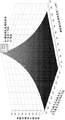
Fig. 6 provides a plot showing gain in the pointing angle of an optical fiber as a function of the diameter to pitch ratio of the region of reduced mass and as a function of the diameter of the region of reduced mass.
Detailed Description
Described herein are embodiments of optical fibers, fiber oscillators, and scanning fiber displays. The disclosed optical fiber advantageously provides improvements in oscillation amplitude or pointing angle for a fixed oscillation or resonant frequency, such as when compared to a fiber oscillator having the same fixed oscillation or resonant frequency but utilizing a conventional optical fiber.
Due to their construction and material properties, the disclosed optical fibers have different mechanical properties than those of conventional optical fibers. For example, a conventional optical fiber may include a core region and a cladding region to define a waveguide element. These regions may be solid bodies of optical material having different refractive indices in order to achieve total internal reflection and to waveguide the light beam down the axis of the optical fiber.
The optical fibers disclosed herein (also referred to as microstructured optical fibers) may optionally utilize similar waveguide elements of materials having different refractive indices, for example, but which also include mechanical regions surrounding the waveguide elements, such as mechanical regions that are not primarily used to guide the optical beam, but rather are used to tune, select, or otherwise modify the mechanical properties of the optical fiber, such as to achieve desired mechanical properties. As an example, one or more area second moment tuning regions may be included in the mechanical region that may be used to modify the second moment of the area of the optical fiber compared to the same optical fiber except that it does not include the one or more area second moment tuning regions. In a particular example, the second moment of the area may be adjusted by modifying the mass of the mechanical region. For example, one or more quality-tuning regions may be included in the mechanical region that may be used to reduce the mass or mass per unit length of the optical fiber as compared to the same optical fiber except that it does not include one or more quality-reducing regions. Example mass tuning regions include air-filled regions (or other gas-filled regions) or regions comprising other materials having a density less than the density of the material used for the waveguide element or mechanical region. For example, plastic, polymer or glass having a density less than the material used in the waveguide element or mechanical region may be employed. This reduction in quality may, for example, allow for the production and use of optical fibers of desired mechanical properties. In addition, the reduction in mass may correspond to a modification of the area moment of the mechanical region.
It will be understood that the same optical fiber may refer to two optical fibers having the same geometry, material, and/or construction, and reference to an exception between the same optical fibers may refer to the exception being a different characteristic of one optical fiber from the other, such as one optical fiber being microstructured and one optical fiber being not microstructured. For example, the optical fiber may include a core, such as a core having a first cross-sectional dimension (such as a diameter) and made of a first optical material; and a cladding around the core, such as a cladding having a second cross-sectional dimension (such as an outer diameter) and made of a second optical material. The same fiber except that it includes one or more mass-tuning regions (such as air or gas-filled regions) may refer to a microstructured fiber as follows: comprising a core, such as a core having a first cross-sectional dimension and made of a first optical material; a cladding around the core, such as a cladding having a second cross-sectional dimension and made of a second optical material; and one or more mass tuning regions in the cladding. It will be understood that the same fiber may have other characteristic differences than the areas of reduced mass that occur due to the presence of the areas of reduced mass, such as a different mass per unit length, or a different resonant frequency for a fixed oscillating fiber length, or a different oscillating fiber length for a fixed resonant frequency.
It will also be appreciated that the same optical fibers may have slightly different characteristics depending on whether certain properties are the same between the same optical fibers. For example, two optical fibers that are identical and have the same oscillation length except for including the microstructured mechanical region will have different resonant frequencies, such as where the microstructured optical fiber has a higher resonant frequency. As another example, two optical fibers that are identical and have the same resonant frequency except for including a microstructured mechanical region will have different oscillation lengths, such as where the microstructured optical fiber has a longer oscillation length.
Advantageously, the disclosed optical fiber can provide an improved field of view for a scanning fiber optic display for a given scanning frequency. For example, a scanned fiber optic display using a microstructured fiber comprising a mechanical region comprising one or more areas of reduced mass can have an increased field of view compared to the field of view of a scanned fiber optic display using the same fiber having the same resonant frequency (i.e., a non-microstructured fiber) except that it does not comprise one or more areas of reduced mass. Since field of view may be a limiting factor in consumer acceptance of augmented reality devices, increasing field of view may be beneficial for increasing consumer adoption. It will be appreciated that in some scanned fibre display embodiments the field of view may be increased by increasing the length of the oscillating fibre for a given operating frequency, as this will result in an increase in the maximum pointing angle of the oscillating fibre.
Fig. 1A provides a schematic diagram of an exemplary fiber optic system 100. The exemplary fiber optic system includes a light source 105, coupling optics 110, and an optical fiber 115. For example, the light source 105 may include a light emitting diode, a laser, or other visible light source. The light source 105 may optionally comprise a plurality of sub-sources or a polychromatic light source, such as a source outputting different wavelengths of electromagnetic radiation. In an embodiment, the light source 105 may be switchable, such as to allow control over the output or intensity of the light source 105 as a function of time.
As illustrated, the optical fiber 115 includes a core 120 and a cladding 125 and has an axis 130, which axis 130 may correspond to, for example, an optical axis or a waveguide axis. Light from the light source 105 coupled into the core 120 and waveguided along the length of the optical fiber 115 may be output at the opposite end of the optical fiber 115. It will be appreciated that the spot shape and direction of light output from the optical fiber 115 may depend on the geometry, material, and/or numerical aperture of the optical fiber 115. Typically, the output from the fiber exhibits a tapered shape 135, with the angle of the taper 135 again defined by the geometry, material, and/or numerical aperture of the fiber 115. In terms of field of view, the fiber 115 in the non-oscillating configuration does not exhibit an increase in field of view 140 beyond the angle of the taper 135. In terms of deflection angle, fiber 115 in a non-oscillating configuration exhibits a deflection angle of zero.
Fig. 1B provides a schematic illustration of a fiber optic system 150, such as may be present in a scanning fiber optic display system. General details of scanning fiber display systems can be found, for example, in U.S. patent application No. 14/156,366, filed on 15/1/2014 and disclosed under publication No. US2015/0268415, which is incorporated herein by reference in its entirety.
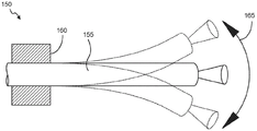
Fig. 1B omits depiction of any light sources or coupling elements from the fiber optic system 150 so as not to obscure other details. The fiber optic system 150 includes an optical fiber 155 (which may correspond to the optical fiber 115) and an actuator 160. An actuator 160 may be used to impart an oscillating motion into the fiber 155. The oscillation of the fiber 155 can be modeled as or correspond to a cantilever oscillator having a fixed end and a free end. For example, the actuator 160 may be or include a piezoelectric actuator, an electromagnetic voice coil, or a thermal actuator. The actuator 160 may allow control of the oscillating motion of the optical fiber 155 in two dimensions and may include two or more independently actuatable shafts. The extent of the oscillatory motion of optical fiber 155 is depicted by the dashed line in FIG. 1B. Due to the oscillating motion, the fiber 155 exhibits an increase in field of view that exceeds the output taper of the fiber 155. In terms of field of view, the fiber optic system 150 exhibits a field of view 165 that is larger than the output taper of the optical fiber 155.
Fig. 2A provides a schematic cross-sectional view of an optical fiber 200. The optical fiber 200 may correspond to a conventional optical fiber and includes a core 205 and a cladding 210 surrounding the core 205. The core 205 is illustrated as having a core diameter 215 and the cladding 210 is illustrated as having an outer diameter 220. It will be appreciated that the core diameter 215 and the outer diameter 220 may be characteristic of a particular fiber embodiment, and thus may have any suitable values.
It will be understood that, unless otherwise indicated, the dimensions of features illustrated in the figures may not be to scale, but that some aspects of the figures or different figures are depicted to illustrate differences in dimensions between different configurations or elements. It will also be understood that additional materials (such as bumpers, jackets, or other coating or protective materials) may be constructed outside of the cladding or mechanical region, but may not be shown in the figures.
FIG. 2B provides a schematic cross-sectional view of an embodiment of a microstructured optical fiber 230. Microstructured optical fiber 230 includes a waveguide element 235 and a mechanical region 240 about the waveguide element. For purposes of illustration, dashed lines are shown in fig. 2B to better identify the transition between waveguide element 235 and mechanical region 240. In fig. 2B, waveguide 235 includes a core 245 and a cladding 250 surrounding core 245. Core 245 is depicted as having a core diameter 255, waveguide 235 is depicted as having a cladding diameter 260, and optical fiber 230 is depicted as having an outer diameter 265.
The reduced mass regions 275 may be uniformly and/or regularly distributed throughout the mechanical region 240, and any suitable or desired geometry and distribution may be used in order to obtain the particular mechanical properties of interest for the microstructured optical fiber 230. It will be appreciated that the reduced mass regions 275 may be arranged along axes that are parallel to each other and/or to the fiber axis (such as the waveguide axis or the optical axis). Alternatively, the areas of reduced mass 275 may be arranged along other directions that are perpendicular to the optical axis or at an angle relative to the optical axis (such as along intersecting axes), however, at least a portion of the mechanical region 240 comprises an area of reduced mass. The reduced mass areas 275 may also be randomly, uniformly, or non-uniformly distributed throughout the mechanical region 240 (optionally along a non-specific axis). As illustrated in fig. 2B, the reduced-mass region 275 exhibits a uniform cross-section, which is shown as circular and has a diameter 280. The pitch 285 corresponds to center-to-center spacing between adjacent reduced mass areas 275. The reduced-mass region 275 may exhibit symmetry, such as cylindrical symmetry, about an axis (such as a waveguide axis or an optical axis) of the microstructured optical fiber 230. The optical fiber 230 may optionally exhibit rotational symmetry.
Without limitation, the microstructured optical fiber 230 can be constructed by stacking lengths of material of appropriate dimensions to form an overall preform structure intended for use in generating the microstructured optical fiber 230 (such as by using solid and/or hollow tubes of suitable diameter, wall thickness, material, shape, etc.). Exemplary glasses may include, but are not limited to, silica glass, fluoride glass, phosphate glass, chalcogenide glass. In some embodiments, plastics or polymers such as polymethylmethacrylate, polystyrene, fluoropolymers, or polysiloxanes may be used. Depending on the manufacturing method and materials, the preform may be placed in a furnace to heat and fuse different parts of the preform, and the heated preform may be drawn into a strand of optical fiber. Alternatively, extrusion methods may be used, such as for optical fibers comprising polymers or plastic materials. It will be appreciated that various techniques, materials and methods may be used to manufacture optical fibers and that many commercial optical fiber manufacturers exist and may provide services for manufacturing optical fibers based on specified parameters.
For illustrative purposes of comparison, the core diameter 215 of the core 205 of the optical fiber 200 may optionally be the same as the core diameter 255 of the core 245 of the microstructured optical fiber 230. The outer diameter 220 of the optical fiber 200 can optionally be the same as the outer diameter 265 of the microstructured optical fiber 230. Core 205 and core 255 may optionally comprise the same material. Cladding 210 and cladding 250 and solid region 270 (non-mass-reduced region) of mechanical region 240 may optionally comprise the same material. In this aspect, the optical fiber 200 can be considered the same as the microstructured optical fiber 230, except that the microstructured optical fiber 230 includes a region of reduced mass 275, while the optical fiber 200 includes a solid cladding 210 that does not include a region of reduced mass.
The various components of the microstructured optical fiber 230 can have any suitable dimensions, and certain dimensions can be selected to provide specific properties, such as optical and mechanical properties. For example, the core 245 may have a diameter of, but is not limited to, about 5 μm to about 25 μm. It will be understood that, as used herein, the term about is intended to include variations around the specified values, such as variations that would not modify the effect of the operation if the values were slightly smaller or slightly larger. In some embodiments, the term about may relate to the precision or tolerance of the value. In some embodiments, the term about may correspond to a variation of ± 1% or less, a variation of ± 5% or less, or a variation of ± 10% or less.
As another example, the waveguide element 235 may have a diameter of, but is not limited to, about 5 μm to about 200 μm (such as about 5 μm to about 125 μm). In some embodiments, cladding 250 may have a diameter or thickness of, but is not limited to, about 5 μm to about 200 μm (such as about 5 μm to about 125 μm), and may optionally be considered to encompass the mechanical region or may be an integral or monolithic body (unitary body) with mechanical region 240 and thus may have a diameter or thickness corresponding to outer diameter 265. The outer diameter 265 may also have any suitable value, such as about 10 μm to about 200 μm, and may match the outer diameter 220 of the conventional optical fiber 200. Exemplary outer diameters may include about 40 μm, about 50 μm, about 80 μm, about 100 μm, about 125 μm, about 150 μm, about 175 μm, and about 200 μm.
Each of the reduced mass areas 275 may have any suitable size or shape, and may for example have cross-sectional dimensions (such as diameter, radius, side length, or axial length) such as, but not limited to: about 1 μm to about 25 μm, about 1 μm to about 5 μm, about 5 μm to about 10 μm, about 10 μm to about 15 μm, about 15 μm to about 20 μm, or about 20 μm to about 25 μm. The pitch 280 between the reduced mass regions 275 can also have any suitable dimension and can be defined by the cross-sectional dimension of the reduced mass regions 275. For example, the pitch 280 may be greater than the diameter of the reduced mass region 275. The pitch 280 can have a length of, but is not limited to, between about 1 μm to about 25 μm, about 1 μm to about 5 μm, about 5 μm to about 10 μm, about 10 μm to about 15 μm, about 15 μm to about 20 μm, or about 20 μm to about 25 μm. The mass reduction fraction of the optical fiber 230 and/or the mechanical region 240 can have any suitable value based on the size, number, spacing, and arrangement of the mass reduction regions. In an embodiment, the plurality of mass-reduction regions occupy between about 1% and 90% of the volume of the optical fiber 230 or the volume of the mechanical region 240. Optionally, the plurality of mass-reduced regions comprises between about 30% and about 90%, about 30% or more, about 40% or more, about 50% or more, about 60% or more, about 70% or more, about 80% or more, or about 90% of the volume of the optical fiber 230 or the volume of the mechanical region 240.
Depending on the particular configuration, in some embodiments, the quality-reducing region may exhibit 4 degrees (4-fold) or 6 degrees (6-fold) or other symmetry about the axis of the microstructured optical fiber, such as cylindrical symmetry, rotational symmetry, or radial symmetry. In addition, other cross-sectional shapes for the reduced mass region may be utilized. For example, the cross-section of the reduced-mass region may exhibit a polygonal shape (such as triangular, square, rectangular, hexagonal, etc.), a circle, or an oval, or any other suitable shape. In some embodiments, the cross-section of the mass-reduced area may have a regular symmetrical shape, such as a circle, oval, ellipse, polygon, or the like. In embodiments, a combination of differently cross-sectionally shaped areas of reduced mass may be utilized. In embodiments, the spacing between adjacent quality-reduction regions may be uniform or non-uniform. In embodiments, the cross-sectional dimensions (such as diameter, radius, axial length, side length, etc.) of the different mass reduction regions may be uniform or non-uniform.
Fig. 3A-3D depict schematic cross-sectional views of different microstructured optical fibers exhibiting a waveguide element surrounded by a mechanical region, according to various embodiments. Microstructured optical fiber 300A in fig. 3A includes multiple rows of reduced mass regions concentrically arranged about a central waveguide element. Microstructured optical fiber 300B in fig. 3B includes circular quality-reducing regions arranged in a 6 degree symmetric configuration. Microstructured optical fiber 300C in fig. 3C includes square quality-reducing regions arranged in a 4 degree symmetric configuration. Microstructured optical fiber 300D in FIG. 3D includes concentric rings of oval-shaped areas of reduced mass.
While the waveguide elements of the microstructured optical fibers described above correspond to conventional core/cladding regions, other waveguide element configurations are possible and contemplated. For example, in some embodiments, multiple core regions may be surrounded by a single cladding or region. Additionally, the plurality of optical fibers may be arranged in a side-by-side or two-dimensional array configuration to provide an additional field of view for a scanned fiber optic display (also referred to as a fiber optic scanned display). U.S. patent application No. 14/156,366 describes hexagonally packed multi-core optical fibers (such as comprising 7 or 19 cores in a hexagonally arranged configuration), and an oscillating optical fiber array for a fiber-optic scanning display. It will be appreciated that in embodiments, a change in refractive index between materials (such as between the core and cladding or between glass and air) may provide a waveguide effect (such as by the process of total internal reflection). As such, the transition between materials may be all that is required to achieve waveguiding, and thus the large cladding of conventional optical fibers may be modified to include a region of reduced mass while still maintaining a solid central portion around the core that provides the higher index material of the waveguide. Various fiber configurations are possible, including single mode and multi-mode configurations. For the purpose of creating optical displays, it is beneficial for the optical fibers to have high transparency/low loss in the visible electromagnetic region.
For comparison purposes, fig. 4A and 4B provide schematic diagrams of fiber optic systems 400 and 450. The fiber optic systems 400 and 450 may be used, for example, in scanning fiber optic display systems. Fig. 4A and 4B omit depiction of any light sources or coupling elements from fiber optic systems 400 and 450 so as not to obscure other details. In fig. 4A, a fiber optic system 400 includes an optical fiber 405 and an actuator 410. Also shown in fig. 4A is a cross-section 415 of the optical fiber 405 illustrating that the optical fiber 405 is a conventional optical fiber including a core and a cladding. The actuator 410 may be used to impart an oscillating motion into the fiber 405. The extent of the oscillating motion of the fiber 405 is depicted by the dashed line in fig. 4A. In terms of field of view, the fiber optic system 400 exhibits a field of view 420. The cantilevered portion of the optical fiber 405 has a length 425.
In FIG. 4B, an optical fiber system 450 includes a microstructured optical fiber 455 and an actuator 460. Also shown in FIG. 4A is cross-section 465 of microstructured optical fiber 455 illustrating that microstructured optical fiber 465 includes a waveguide element and a microstructured mechanical region about the waveguide element that includes a plurality of reduced mass regions. The actuator 460 may be used to impart an oscillating motion into the microstructured optical fiber 455. The actuator 460 can oscillate at about our resonant frequency of the microstructured fiber 455, such as within 5% of the natural frequency of the microstructured fiber 455 or within 1% of the resonant frequency of the microstructured fiber 455. In an embodiment, the resonant frequency may correspond to an eigenfrequency or a natural frequency. In an embodiment, the actuator 460 operates at a frequency that provides gain in the pointing angle or deflection of the microstructured fiber 455. The extent of the oscillating motion of microstructured fiber 455 is depicted by the dashed line in FIG. 4B. In terms of field of view, the microstructured fiber system 450 exhibits a field of view 470. The cantilevered portion of microstructured optical fiber 455 has a length 475.
It will be appreciated that the resonant frequency of a cantilevered fiber may be generally proportional to the square of the length of the cantilever. For example, if the length 425 of the fiber 405 is doubled, the resonant frequency of the fiber 405 is expected to increase by a factor of 4. Similarly, if the length 475 of the microstructured optical fiber 455 is halved, it would be desirable to reduce the resonant frequency of the microstructured optical fiber 475 by a quarter.
It will also be appreciated that the distribution of the mass of the cantilever fiber may also affect the resonant frequency. For example, assuming that the optical fiber 405 and the microstructured optical fiber 455 are the same (diameter, material, etc.) except for the reduced mass region of the microstructured optical fiber 455, including the reduced mass region can reduce the mass per unit length of the microstructured optical fiber 455 as compared to the optical fiber 405. Thus, in order for the resonant frequencies of optical fiber 405 and microstructured optical fiber 455 to be the same, optical fiber 405 and microstructured optical fiber 455 will exhibit different lengths, where length 425 is less than length 475. Advantageously, this difference in length will allow the field of view 470 and/or pointing angle of the microstructured fiber 455 to be greater than the field of view 420 and/or pointing angle of the fiber 405.
It will be appreciated that other characteristics of the optical fiber may affect the resonant frequency and/or the pointing angle of the optical fiber, such as the maximum pointing angle. Example characteristics that may affect the frequency or pointing angle include fiber outer diameter, diameter of the waveguide element, mass reduction fraction, number of mass reduction regions, distribution and cross-sectional dimensions (e.g., diameter), pitch between adjacent mass reduction regions, mass reduction region material density, waveguide element design, core material, cladding material, solid material of the mechanical region, and the like.
In some embodiments, a scanning fiber optic display utilizes the oscillating motion of a cantilevered fiber to project an image using the fiber. For example, the oscillatory motion of the cantilever fiber may be controlled in two dimensions to generate a spiral pattern, such as by appropriately driving an actuator. In some embodiments, the input light may be controlled and timed such that the output of the oscillating optical fiber may generate a desired image within the spiral pattern with a repetitive oscillating motion and timed light output for generating the sequence of images. U.S. patent application No. 14/156,366 describes how a cantilevered fiber may be used to generate a projection image or sequence of images. However, embodiments described herein advantageously allow the field of view, pointing angle, and projected output image size and/or resolution of a scanning fiber optic display to be increased by using microstructured optical fibers.
For example, fig. 5A depicts a spiral pattern 500 for a conventional scanning fiber display (such as similar to the fiber system 400 of fig. 4A) that includes a conventional fiber having a core and cladding and no areas of reduced quality in the cladding material. The diameter 505 of the spiral pattern is limited by the maximum pointing angle of the scanning fiber display used.
In contrast, fig. 5B depicts a comparable spiral pattern 550 for a scanning fiber display (such as the fiber system 450 of fig. 4B) containing a comparable microstructured optical fiber comprising a waveguide element and a microstructured mechanical region (which includes multiple quality-reduction regions) around the waveguide element. The spiral pattern 550 exhibits a diameter 555 defined by the maximum pointing angle of the scanning fiber display used.
For the same conventional and microstructured optical fibers (i.e., the same except for the inclusion of the mass-reducing region in the microstructured optical fiber) operating at the same resonant frequency (which implies an increased cantilever length), the diameter 555 of the spiral pattern 550 will be greater than the diameter 505 of the spiral pattern 500, which corresponds to the increase in field of view and/or maximum pointing angle achieved by using the microstructured optical fiber. Without limitation, the use of microstructured optical fibers may advantageously increase the field of view and/or pointing angle by as much as about 30%. In some cases, an increase in field of view and/or pointing angle of up to about 50% or up to about 70% may be achieved. In some embodiments, an increase in field of view and/or pointing angle of between about 30% and about 40% may be achieved.
Various microstructured optical fibers can have different optical and mechanical properties. In some embodiments, the microstructured optical fiber can have one or more of the following optical specifications: a light transmission range of about 435nm to about 645 nm; an output mode field diameter of red, green and/or blue light of about 1.4 μm with a tolerance of about ± 0.15 μm; a numerical aperture of red, green, and/or blue light of about 0.25; an optical transmission loss of less than or about 30dB/km for any or all wavelengths between about 435nm and 645 nm; and low splice loss of single mode (phi 1.2 mu m, NA).
In some embodiments, the microstructured optical fiber may have one or more of the following mechanical specifications: an outer diameter between about 80 μm and about 125 μm or between about 40 μm and about 200 μm; a diameter of the mechanical region between about 40 μm and the outer diameter; a mass reduction fraction (e.g., gas or air fill fraction) in a mechanical region of about 70% or greater; a concentric core/outer diameter of about 500nm or less; a percent difference between the vertical moments of inertia of about 0.4% or less, indicating that the microstructured optical fiber is approximately symmetric in the x and y axes (where z is the fiber length axis); and a weight change of about 1% or less due to water collected in the air-filled region.
It will be understood that rotational symmetry may be useful for the optical fibers disclosed herein and may be advantageous for some embodiments, and thus the microstructured optical fiber may optionally have rotational symmetry. Rotational symmetry may refer to the stiffness (Kr) of the fiber being the same in all radial directions (θ) (see fig. 2A for direct reference). In other words, for forces acting in any radial direction defined by θ, the fiber will only translate in the radial direction. In the static case, the hooke's theorem gives F r =K r ·δ r . With rotational symmetry, it should be noted that there is no translation orthogonal to the radial direction. This can also be characterized by stating that the main direction of the fiber is not unique.
The terms and expressions which have been employed are used as terms of description and not of limitation, and there is no intention in the use of such terms and expressions of excluding any equivalents of the features shown and described or portions thereof, but it is recognized that various modifications are possible within the scope of the invention claimed. Thus, it should be understood that although the present invention has been specifically disclosed by preferred embodiments and optional features, modification and variation of the concepts herein disclosed may be resorted to by those skilled in the art, and that such modifications and variations are considered to be within the scope of this invention as defined by the appended claims.
The foregoing description of the exemplary embodiments of the invention has been presented for the purposes of illustration and description. It is not intended to be exhaustive or to limit the invention to the precise form described, and many modifications and variations are possible in light of the above teaching. The embodiments were chosen and described in order to explain the principles of the invention and its practical application to enable one skilled in the art to utilize the invention in various embodiments and with various modifications as are suited to the particular use contemplated.
When a group of substitutents is disclosed herein, it is to be understood that all individual members and all sub-groups and categories of those groups that can be formed using the substitutents are disclosed separately. When a markush group or other grouping is used herein, all individual members of the group and all possible combinations and subcombinations of the group are intended to be included individually in the disclosure. As used herein, "and/or" means that one, all, or any combination of the items in the list separated by "and/or" is included in the list; for example, "1, 2 and/or 3" is equivalent to '"1' or '2' or '3' or '1 and 2' or '1 and 3' or '2 and 3' or '1, 2 and 3'".
Unless otherwise indicated, each formula or combination of components described or illustrated may be used to practice the present invention. The particular names of the materials are intended to be exemplary and it is well known that one of ordinary skill in the art may name the same materials differently. Those of ordinary skill in the art will understand that methods, apparatus elements, starting materials, and synthetic methods other than those specifically exemplified can be used in the practice of the invention without resort to undue experimentation. All known functional equivalents of any such methods, apparatus elements, starting materials, and synthetic methods are intended to be included herein. Whenever a range (e.g., temperature range, time range, or composition range) is given in the specification, all intermediate ranges and subranges, as well as all individual values included in the given range, are intended to be included in the disclosure. The particular details of the particular embodiments may be combined in any suitable manner without departing from the spirit and scope of the embodiments of the invention. However, other embodiments of the invention may relate to specific embodiments relating to each individual aspect or to specific combinations of these individual aspects.
The invention may also be understood by reference to the following non-limiting examples.
Example 1: description of the mechanical merit function:
cantilever optical fiber oscillator
This example describes how to maximize the pointing angle and thus increase the field of view of the end of the fiber while keeping the natural frequency of the oscillator constant. In some embodiments, this may be achieved by minimizing the mass of the cantilever oscillator while maximizing the area second moment. This example yields: how to achieve the best performance (maximum deflection for a given operating frequency) for a thin walled tube fiber for a given size fiber. Advantageously, microstructured optical fibers incorporating this technique can exhibit a merit function increase (i.e., an increase in pointing angle) of approximately 30% or better when compared to the same conventional optical fiber.
To determine the merit function, the second moment of the area of the cross section of the fiber is required. The following definitions are used in the calculation of the second moment of area:
I T,MS second moment of cross-sectional area (T = standard fiber, MS = microstructured fiber)
A T,MS Cross sectional area
A H_i Area of holes (air-filled regions) in the microstructure
r i : perpendicular distance from hole to neutral axis of cross-sectional area
T : subscripts indicating solid optical fibres
MS : subscripts to indicate microstructured optical fiber
J: natural frequency mode/harmonic number
β (j): modulus constant of j-order modulus
d: the diameter of the rod.
For solid rods, I T =d 4 /64. As a constraint, the natural frequency f n Fixed as the same for direct comparison of solid and microstructured designs. For the cantilever beam, the natural frequency is obtained from the euler equation:

for high refresh rates of the display, it is useful to have a high frequency of operation of the scanning fibers. At the same time, it is desirable to achieve a large deflection of the oscillator, since this is proportional to the field of view and resolution.
Since the scanning fiber projector is a resonant device, the operating frequency is approximately equal to the natural frequency (within 1%). This means that we have to select the system parameters such that the system natural frequency as estimated by the above equation remains high.
From the perspective of the microstructured fiber, the above equation gives a direct understanding of the effect of I (area second moment) and a (solid cross-sectional area of a solid fiber minus the area of the hole) on the natural frequency and associated length of the oscillator.
By examining this equation, increasing the ratio of I to A increases the natural frequency. This property can be exploited in microstructured optical fibers by removing the mass near the neutral axis (small effect on I) by inserting holes near the neutral axis, since this has a small effect on I as a function of the square of the distance from the neutral axis while maintaining the mass near the outer diameter or periphery. This is further from the equation below, where it should be shown that the contribution of the cross section (hole) to the second moment of area is a function of the square of the distance from the neutral axis.
According to the parallel axis theorem, the second moment of area of a microstructured optical fiber is:

thus, the cross-section (i.e., the inserted hole or reduced mass area) can be deleted furthest from the neutral axis to raise the natural frequency or increase the oscillator length L for a given natural frequency. The insertion holes allow raising the oscillator natural frequency or increasing the oscillator length (L) for a given natural frequency. Note that all holes have the same effect on area (a) regardless of their location, while the holes closest to the central axis raise the natural frequency more than the holes further from the central axis.
The following figure of merit function analysis describes how a microstructured fiber compares to a solid fiber in terms of deflection angle. In this analysis, the frequency remains constant and the second moment of area and the area of the beam cross-section vary. The merit function quantifies the gain in the deflection angle. Using the above expression for natural frequency:

solving for the value of L that constrains the frequency to a constant yields:


fixed frequency (f) n ) Density (ρ), modulus constant (β L (n)) i ) Modulus (compare 1 st order modulus to 1 st order modulus, 2 nd order modulus to 2 nd order modulus, etc.) and modulus (E) are constant, with the above expression reduced as follows:


The response at resonance is identified as scaling with static deflection according to the frequency response function. Thus, the static deflection of the beam at the point and distributed load is considered. In each case, the ratio of the deflection of the structured device to the deflection angle of the solid fiber cantilever was determined. Note that the microstructured pattern can be optimized for maximum deflection, but it must also be tuned for transmission of visible light with single mode.
The slope of the beam is calculated using the concentrated load at the end:

where α is the deflection angle, E is the Young's modulus, I is the area second moment, L is the cantilever length, and F is the force. Calculating slope of beam using distributed load

Where W is the load per unit length.
The expression for the angular deflection gain of the constant frequency oscillator is derived as follows. For the concentration force model, assume E MS =E T :


This represents a gain relationship that allows the use of area and area second moment calculations for cross-sections.
For the distributed force model:


this represents a gain relationship that allows for the calculation using the area of the cross section and the second moment of the area.
Approximating the dynamic mode shape as the dynamic mode shape of the distributed load for relative stress calculation:


assuming z and ρ are constants:

this indicates that the reduced mass fiber has a longer cantilever length for the same oscillation frequency.
FIG. 6 provides a plot showing a merit function for gain in pointing angle for a microstructured fiber on a solid or conventional fiber based on a 125 μm fiber outer diameter based on the above equation. While this example describes mass reduction in terms of air-filled regions, it will be understood that other mass reducing materials may be used under similar analysis. The plot provides a surface showing the maximum gain in pointing angle of the fiber as a function of the diameter to pitch ratio of the air-filled region and as a function of the diameter of the air-filled region, and indicates the effect of the fiber. It will be appreciated that the maximum gain possible is desirable, but certain mechanical considerations must be taken into account. For example, the fiber must be able to oscillate without breaking. As such, the diameter of the microstructured region should be less than the outer diameter of the optical fiber so that the optical fiber has mechanical integrity. Furthermore, the ratio of the diameter of the air-filled region to the pitch of the air-filled region should be less than 1, otherwise the air-filled region will overlap and occupy an unusable amount of fiber. As illustrated in fig. 6, a diameter of the microstructured (air-filled) region of 102.9 μm and a diameter/pitch of 0.873 are expected to provide a gain of 1.725, which corresponds to a 72.5% increase in steering angle.
Example 2: microstructured optical fiber performance analysis
The requirement to maximize the natural frequency of the mechanical system is straightforward. For setsGeneral parametric systems, such as mass, natural frequency f, of a spring connected with a single degree of freedom without damping n (Hz) is the modal stiffness And modal mass m (kg). The natural frequency is

In this case, for a given constraint on the problem, there are only two parameters and the stiffness can be increased or the mass reduced to raise the natural frequency. For a truly continuous system, like a cantilever beam, the relationship between the fiber scanner (with modulus E, density ρ, cross-sectional area a, and area second moment I), mass distribution, material properties, boundary conditions (holding method for the fiber) and beam size illustrated in fig. 1B should also be considered, as well as the operating parameters of the display (field of view, refresh rate, resolution). It is possible to vary the geometrical function of the length of the beam. This is usually done in the case of a cone beam, but is not considered here. Instead, microstructured or photonic bandgap fiber is examined for its potential benefits. A brief background of the oscillator is provided first.
The natural frequency equation for the lateral motion of the Euler Bernoulli Beam (Euler Bernoulli Beam) is

Wherein:
angle of orientation and end of cantilever fiber
I,I T,MS : second moment of cross-sectional area
T : subscript of standard, straight, cylindrical optical fiber
MS : subscripts of microstructured optical fibers
A,A T,MS The cross-sectional area of the cantilever (constant in length-i.e., no tapered fiber).
A H_i The area of the holes in the microstructure (which is not constant in some designs).
r i Vertical distance from hole to neutral axis
T : subscript indicating solid conventional optical fiber
MS : subscripts to indicate microstructured optical fiber
i: vibration modulus (e.g., 1 st, 2 nd, 3 rd order modes of vibration and natural frequency)
β (i): the modulus constant for the i-order mode depends on the boundary conditions (cantilever, free, simple support)
D: outer diameter of oscillator (optical fiber)
d: vibrator (fiber) inside diameter for tubes
Delta. transverse beam deflection
L: cantilever length
E: young's modulus
ρ: density of
fn: natural frequency of the beam-only the 1 st order mode is considered
SM: specific modulus (or specific stiffness)
R g : radius of gyration
Xi: damping ratio of oscillator
The radius of gyration is defined above as

By examining equation 2, the effect of the independent variables on the natural frequency of the beam can be identified as follows:
increase of Young's modulus (E), increase of natural frequency
Increase of area second moment (I), increase of natural frequency
Increase density, decrease natural frequency
Increase of the cross-sectional area (A), decrease of the natural frequency
Increase length (L), decrease natural frequency
The natural frequency varies linearly with the modulus constant (β). The constant is a function of the boundary condition. Any one or more of the following may be performed to raise the natural frequency.
The boundary conditions are modified.
The waveguide holding method is changed to increase the constant β L (i). The retention method is limited by stability requirements, driving energy coupling and manufacturing methods.
The material properties are modified.
Increasing the Young's modulus (E). This is difficult because the optical waveguide material is limited.
The density (p) is reduced. This is also difficult because optical waveguide materials are limited, particularly in the context of high volume production.
These objectives are defined by the introduction Or specific modulus or specific stiffness. Therefore, maximizing specific stiffness may be desirable, although this is limited by commercial materials. This balances the changes in material properties to allow direct material comparisons.
The mass distribution is modified.
The cantilever length (L) is reduced. While this is possible, such a change may reduce lateral deflection (static deflection and L for applied end loads) 3 Proportional ratio).
The cross-sectional area (A) is reduced. This reduces the mass, but also the area second moment (I) and thus the stiffness.
The second moment of area (I) is increased. To the extent that the increase in the second moment of area is greater than the increase in area, this increases the natural frequency. Increasing the cross-sectional area and thus increasing the mass that reduces the natural frequency. Thus, the ratio of I to A here Is an important factor. It is therefore advantageous to normalize the second moment of area (I) with respect to (a). Recall from equation 3 that this is the definition of the radius of gyration. This is a useful approach when designing microstructured oscillators. See equation 14.
Therefore, it is useful to normalize the mass distribution effect on natural frequencies, as well as material properties. Advantageously, this is done by the nature of the radius of gyration used to describe the distribution of the area about the central axis.
From equation 2, a proportional relationship defining the oscillator design trade space can be used (the elements removed from the relationship are constants). This proportional relationship is used because of the relative performance of different oscillator types that is of interest. Based on equation 2:
at the natural frequency f of the beam n In one aspect,

f n ∝R g (5)


for a fixed frequency, the cantilever length (L) is


Square root of frequency gain versus specific modulus, radius of gyration (square root of I/A), boundary constant between different oscillators Proportional and inversely proportional to the square root of the cantilever length.
In fiber scanning applications, the natural frequency (f) is simultaneously tuned n ) And maximizing lateral deflection (δ) is desirable. The maximum achievable deflection is identified in equation 11, where, in general, an increase in natural frequency corresponds to a decrease in lateral deflection. Thus, a change in length is not always useful in increasing overall system performance without other changes.
Recall that for quasi-static analysis, the deflection of a cantilever beam with distributed loading per unit length is

However, load and boom length (L) are distributed 1 ) Is proportional, so the deflection (δ) is related to the cantilever length by
δ∝L 3 (12)
Therefore, it can be determined from equation 8 according to the radius gyration (R) g ) Writing a merit function:


to compare two oscillators (subscripts 1, 2) with the same natural frequency, the deflection gain is:

and the pointing angle gain is:

these merit functions were applied to the microstructured fiber to explore the expected relative gain compared to a conventional untapered fiber oscillator.
The radius of gyration of a hollow core optical fiber having an outer diameter (D) and an inner diameter (D) is:

thus, for microstructured optical fibers, the highest value of the radius of gyration is achieved for thin walled tubes.
The radius of gyration for a solid fiber is:

since the natural frequency of the oscillator is proportional to the radius of gyration, this parameter can be maximized for a given fiber diameter.
Second moment of area of

The area of the cross-sectional optical fiber is

To illustrate the gain achieved by microstructured fibers, consider an example based on some common fiber dimensions and the microstructured cross-section (limit) of a thin walled tube. Consider simplified models of a 125 μm diameter solid optical fiber and a 125 μm diameter microstructured optical fiber having a 10 μm wall thickness (internal diameter 105 μm).
The second moment of area of the solid fiber is

The cross-sectional area of the solid optical fiber is

The second moment of area of the microstructured optical fiber is

The cross-sectional area of the microstructured optical fiber is

The ratio of the turning radii is

Using the relative deflection gain according to equation 14, and substituting the results according to equation 23 to obtain the best case gain for a 125 μm outer diameter fiber (hollow core) with a 10 μm wall thickness, the deflection gain for microstructured fibers is such that it is compared to solid fibers

Thus, this change results in a 50% increase in deflection for a given natural frequency and material.
Now, all parameters for both designs are determined for verification. Equation 2 is solved for the cantilever length:

calculate the cantilever length for a solid fiber:

calculating the cantilever length for the microstructured fiber:

the merit function was validated and the results compared using equation 8:

finally, to examine the results, the expected deflections were compared for constant load using quasi-static analysis as a merit function from equation 24:

finally, applying equation 14 directly based on the radius gyration according to equation 23 provides a deflection gain:

note that the 1.5x gain described herein is based on an ideal 10 μm wall thickness for an optical fiber having an outer diameter of 125 μm. In practice, the result is slightly smaller for real fibers of the same size.
Equation 2 can be solved for length as

According to this

From equation 31, it is apparent that the length is maximized when the area second moment to area ratio is maximized.
As another example, a solid fiber having an outer diameter of 80 μm and a natural frequency of about 60kHz was considered and compared to a microstructured fiber having an overall air-fill fraction of about 43.7% (as modeled above with an 80 μm fiber having a 10 μm wall thickness) and a natural frequency of about 60kHz to determine an increase in pointing angle.
The second moment of area of the microstructured optical fiber is

The cross-sectional area of the microstructured optical fiber is

The length of the microstructured fiber was:

the second moment of area of the solid fiber is

The cross-sectional area of the solid fiber is:

the length of the solid fiber is:

the ratio LMS/LT of the length of the microstructured fiber to the solid fiber was 1.12. Using equation 16, the relative increase in pointing angle is

Thus, by microstructuring the 80 μm fiber, the pointing angle can be increased by 25%.
Example 3: example fibers for scanning fiber displays
This example describes microstructured fiber embodiments comprising a plurality of reduced quality regions and the use of the fiber in a scanning fiber display. Microstructured optical fibers are made by stacking lengths of optical silicon tubing to form an overall preform structure. A single solid tube of optical material is positioned at the center of the preform and serves as the core of the waveguide region corresponding to the last formed optical fiber. A series of solid silicon tubes are positioned around the solid tube in the preform and serve as cladding corresponding to the waveguiding region of the finally formed optical fiber. Hollow silica tubes are positioned around a series of solid silica tubes in the preform and are used for a quality tuning region corresponding to the mechanical region of the final formed optical fiber. Finally, a ring of solid silicon tube is positioned outside the hollow silicon tube and serves as the outer solid edge or perimeter corresponding to the mechanical region of the last formed fiber. The assembled preform is heated to fuse the components to one another and then drawn into an optical fiber according to known optical fiber drawing techniques.
The resulting optical fiber corresponds to a microstructured optical fiber. The resulting fiber has a core region (such as a core having a diameter of about 5 μm), a cladding region (such as having an outer diameter of about 25 μm), and a mechanical region having a diameter of about 80 μm. The microstructured optical fiber exhibits an overall air-fill fraction of, for example, about 44%. The microstructured optical fiber exhibits a corresponding reduced mass in the mechanical region as compared to an equivalent non-microstructured optical fiber.
A scanning fiber optic display is created by positioning a microstructured optical fiber in a cantilever configuration relative to a mechanical actuator such that the length of the microstructured optical fiber is free (i.e., unsupported). The length of the unsupported portion of the microstructured optical fiber was about 1.159mm. The 1.159mm cantilever microstructured fiber exhibited a resonant frequency of about 60 kHz. The maximum pointing angle of the microstructured fiber when oscillated at the resonant frequency was about 12.5 degrees.
In comparison, an equivalent non-microstructured (i.e., solid) fiber in a cantilever configuration having a resonant frequency of about 60kHz (i.e., the same resonant frequency as the microstructured fiber described above) had a length of about 1.037mm and had a maximum pointing angle of about 10 degrees.
Claims (20)
1. An optical fiber, comprising:
a waveguide element extending along an axis;
a mechanical region around the waveguide element, wherein the mechanical region is positioned between the waveguide element and an outer periphery, and wherein the mechanical region comprises a first material having a first density; and
a plurality of mass tuning regions positioned within the mechanical region, wherein the plurality of mass tuning regions comprise a second material having a second density less than the first density, wherein the plurality of mass tuning regions are arranged within the mechanical region such that the optical fiber exhibits a percent difference between vertical moments of inertia of 0.4% or less.
2. The optical fiber of claim 1, wherein the waveguide element comprises a central core region and a cladding around the central core region.
3. The optical fiber of claim 2, wherein the cladding comprises the first material, and wherein the central core region comprises a third material.
4. The optical fiber of claim 2, wherein the cladding and the mechanical region comprise a monolithic body.
5. The optical fiber of claim 1, wherein the waveguide element comprises a plurality of core regions and a cladding around the plurality of core regions.
6. The optical fiber of claim 1, wherein the plurality of mass tuning regions comprises one or more gas-filled regions, air-filled regions, one or more polymer-filled regions, one or more glass-filled regions, one or more evacuated regions, or any combination thereof.
7. The optical fiber of claim 1, wherein the plurality of mass tuning regions comprise a plurality of rows of mass tuning elements, wherein the rows are concentrically arranged about the waveguide element.
8. The optical fiber of claim 1, wherein the plurality of mass tuning regions are arranged in a symmetric configuration about the axis.
9. The optical fiber of claim 1, wherein the plurality of mass tuning regions are arranged with an axis parallel to the axis.
10. The optical fiber of claim 1, wherein the plurality of mass tuning regions occupy between 30% and 90% of the volume of the mechanical region.
11. The optical fiber of claim 1, wherein the plurality of mass tuning regions reduce the mass per unit length of the optical fiber as compared to a comparable optical fiber comprising a corresponding waveguide element identical to the waveguide element and a corresponding mechanical region identical to the mechanical region except that the corresponding mechanical region does not include a mass tuning region positioned between the corresponding waveguide element and a corresponding outer perimeter of the comparable optical fiber.
12. The optical fiber of claim 1, wherein the optical fiber has an effective cantilever length, and wherein the plurality of mass tuning regions increase a resonant oscillation frequency of the optical fiber compared to a comparable optical fiber having the effective cantilever length and comprising a corresponding waveguide element identical to the waveguide element and a corresponding mechanical region identical to the mechanical region, except that the corresponding mechanical region does not comprise a mass tuning region positioned between the corresponding waveguide element and a corresponding outer perimeter of the comparable optical fiber.
13. The optical fiber of claim 1, wherein the plurality of mass tuning regions increase the effective cantilever length of the optical fiber for a given operating frequency compared to a comparable optical fiber that includes a corresponding waveguide element that is identical to the waveguide element and a corresponding mechanical region that is identical to the mechanical region except that the corresponding mechanical region does not include a mass tuning region positioned between the corresponding waveguide element and a corresponding outer perimeter of the comparable optical fiber.
14. The optical fiber of claim 1, wherein the optical fiber has a resonant frequency, and wherein the plurality of mass tuning regions increase an effective cantilever length of the optical fiber as compared to a comparable optical fiber having the resonant frequency and comprising a corresponding waveguide element identical to the waveguide element and a corresponding mechanical region identical to the mechanical region, except that the corresponding mechanical region does not comprise a mass tuning region positioned between the corresponding waveguide element and a corresponding outer perimeter of the comparable optical fiber.
15. A scanning fiber optic display, comprising:
an optical fiber, wherein the optical fiber comprises:
a waveguide element extending along an axis;
a mechanical region around the waveguide element, wherein the mechanical region is positioned between the waveguide element and an outer periphery, and wherein the mechanical region comprises a first material having a first density; and
a plurality of mass tuning regions positioned within the mechanical region, wherein the plurality of mass tuning regions comprise a second material having a second density that is less than the first density, wherein the plurality of mass tuning regions are arranged within the mechanical region such that the optical fiber exhibits a percentage difference between vertical moments of inertia of 0.4% or less; and
an actuator in mechanical contact with the optical fiber, the actuator for causing oscillation of the optical fiber.
16. A scanning fiber optic display according to claim 15, wherein the actuator comprises a piezoelectric transducer, an electromagnetic voice coil, or a thermal actuator.
17. A scanning fibre optic display according to claim 15 wherein the actuator comprises a two dimensional actuator for controlling the movement of the end of the optical fibre in two dimensions.
18. A scanning fiber optic display according to claim 15, further comprising a visible light source in optical communication with the waveguide element of the optical fiber.
19. A scanning fiber optic display according to claim 15, further comprising a multi-color switchable light source in optical communication with the waveguide element of the optical fiber.
20. An optical fiber, comprising:
a waveguide element extending along an axis;
a mechanical region around the waveguide element, wherein the mechanical region is positioned between the waveguide element and an outer periphery, and wherein the mechanical region comprises a first material; and
a plurality of area second moment adjustment regions positioned within the mechanical region, wherein the plurality of area second moment adjustment regions are arranged within the mechanical region such that the optical fiber exhibits a percentage difference between perpendicular moments of inertia of 0.4% or less, and wherein the plurality of area second moment adjustment regions comprise a second material for generating an area second moment of the mechanical region that is different from a comparable optical fiber that comprises a corresponding mechanical region that is the same as the mechanical region except that the corresponding mechanical region does not include the plurality of area second moment adjustment regions positioned between corresponding waveguide elements and corresponding outer perimeters of the comparable optical fiber.
Applications Claiming Priority (6)
| Application Number | Priority Date | Filing Date | Title |
|---|---|---|---|
| US201662438898P | 2016-12-23 | 2016-12-23 | |
| US62/438,898 | 2016-12-23 | ||
| US201762464298P | 2017-02-27 | 2017-02-27 | |
| US62/464,298 | 2017-02-27 | ||
| CN201780079410.1A CN110100196B (en) | 2016-12-23 | 2017-12-21 | Microstructured fiber oscillator and waveguide for fiber optic scanner |
| PCT/US2017/067973 WO2018119278A1 (en) | 2016-12-23 | 2017-12-21 | Microstructured fiber optic oscillator and waveguide for fiber scanner |
Related Parent Applications (1)
| Application Number | Title | Priority Date | Filing Date |
|---|---|---|---|
| CN201780079410.1A Division CN110100196B (en) | 2016-12-23 | 2017-12-21 | Microstructured fiber oscillator and waveguide for fiber optic scanner |
Publications (2)
| Publication Number | Publication Date |
|---|---|
| CN112363270A CN112363270A (en) | 2021-02-12 |
| CN112363270B true CN112363270B (en) | 2022-12-06 |
Family
ID=62627597
Family Applications (2)
| Application Number | Title | Priority Date | Filing Date |
|---|---|---|---|
| CN202011276836.6A Active CN112363270B (en) | 2016-12-23 | 2017-12-21 | Microstructured fiber oscillator and waveguide for fiber optic scanner |
| CN201780079410.1A Active CN110100196B (en) | 2016-12-23 | 2017-12-21 | Microstructured fiber oscillator and waveguide for fiber optic scanner |
Family Applications After (1)
| Application Number | Title | Priority Date | Filing Date |
|---|---|---|---|
| CN201780079410.1A Active CN110100196B (en) | 2016-12-23 | 2017-12-21 | Microstructured fiber oscillator and waveguide for fiber optic scanner |
Country Status (9)
| Country | Link |
|---|---|
| US (3) | US10451868B2 (en) |
| EP (1) | EP3559715A4 (en) |
| JP (3) | JP7198756B2 (en) |
| KR (2) | KR102534653B1 (en) |
| CN (2) | CN112363270B (en) |
| AU (2) | AU2017382882B2 (en) |
| CA (1) | CA3046847A1 (en) |
| IL (2) | IL301938B1 (en) |
| WO (1) | WO2018119278A1 (en) |
Families Citing this family (10)
| Publication number | Priority date | Publication date | Assignee | Title |
|---|---|---|---|---|
| KR102534653B1 (en) | 2016-12-23 | 2023-05-18 | 매직 립, 인코포레이티드 | Microstructured fiber optic oscillator and waveguide for fiber scanner |
| US10830667B1 (en) | 2018-05-16 | 2020-11-10 | Magic Leap, Inc. | Optical and functional metrology of microstructured optical fibers |
| CN111381363B (en) * | 2018-12-29 | 2022-11-08 | 成都理想境界科技有限公司 | Scanning driver and optical fiber scanner |
| CN111381365A (en) * | 2018-12-29 | 2020-07-07 | 成都理想境界科技有限公司 | Scanning actuator, scanning driver and optical fiber scanner |
| CN111381364A (en) * | 2018-12-29 | 2020-07-07 | 成都理想境界科技有限公司 | Optical fiber scanner |
| WO2020193075A1 (en) * | 2019-03-25 | 2020-10-01 | Asml Netherlands B.V. | Frequency broadening apparatus and method |
| CN111751923B (en) * | 2019-03-29 | 2023-03-10 | 成都理想境界科技有限公司 | Optical fiber and scanning light imaging display device |
| CN111830702A (en) * | 2019-04-19 | 2020-10-27 | 成都理想境界科技有限公司 | Scanning actuator, optical fiber scanner and driving method |
| CN112444962A (en) * | 2019-08-28 | 2021-03-05 | 成都理想境界科技有限公司 | Optical fiber structure and optical fiber scanner |
| CN111061004B (en) * | 2019-12-29 | 2021-03-19 | 中国科学院西安光学精密机械研究所 | Cladding structure of optical fiber |
Citations (5)
| Publication number | Priority date | Publication date | Assignee | Title |
|---|---|---|---|---|
| CN1205443A (en) * | 1997-07-15 | 1999-01-20 | 住友电气工业株式会社 | Optical cable and optical cable bushing |
| CN1449504A (en) * | 2000-08-25 | 2003-10-15 | 悉尼大学 | Polymer optical waveguide |
| JP2004177817A (en) * | 2002-11-28 | 2004-06-24 | Sumitomo Electric Ind Ltd | Optical fiber and optical module |
| CN101061411A (en) * | 2004-06-24 | 2007-10-24 | 康乃尔研究基金会有限公司 | Fibrous-composite-material-based MEMS optical scanner |
| US7590324B1 (en) * | 2008-07-24 | 2009-09-15 | Corning Incorporated | Double-clad optical fibers and devices with double-clad optical fibers |
Family Cites Families (24)
| Publication number | Priority date | Publication date | Assignee | Title |
|---|---|---|---|---|
| WO2002034452A1 (en) | 2000-10-25 | 2002-05-02 | Optek Limited | Laser cutting method and apparatus for optical fibres or waveguides |
| GB0027399D0 (en) * | 2000-11-09 | 2000-12-27 | Univ Southampton | Dispersion tailoring using holey optical fibres |
| US6856712B2 (en) * | 2000-11-27 | 2005-02-15 | University Of Washington | Micro-fabricated optical waveguide for use in scanning fiber displays and scanned fiber image acquisition |
| US6512871B2 (en) * | 2001-02-12 | 2003-01-28 | Gazillion Bits, Inc. | Dispersion compensating fiber with void pattern in secondary core |
| US7616986B2 (en) * | 2001-05-07 | 2009-11-10 | University Of Washington | Optical fiber scanner for performing multimodal optical imaging |
| BR0212552A (en) * | 2001-08-29 | 2004-12-28 | Monsanto Technology Llc | Zea mays constitutive photomorphogenesis 1 (cop1) nucleic acid sequence and use thereof |
| US7590323B2 (en) * | 2001-08-30 | 2009-09-15 | Crystal Fibre A/S | Optical fibre with high numerical aperture, method of its production, and use thereof |
| JP3802843B2 (en) * | 2002-06-14 | 2006-07-26 | 正隆 中沢 | Optical fiber manufacturing method |
| JP5065008B2 (en) | 2005-03-18 | 2012-10-31 | 古河電気工業株式会社 | Optical fiber and waveguide |
| US8537203B2 (en) * | 2005-11-23 | 2013-09-17 | University Of Washington | Scanning beam with variable sequential framing using interrupted scanning resonance |
| WO2007084915A2 (en) * | 2006-01-17 | 2007-07-26 | University Of Washington | Scanning fiber-optic nonlinear optical imaging and spectroscopy endoscope |
| EP2115503A2 (en) * | 2007-02-28 | 2009-11-11 | Corning Incorporated | Optical fiber with large effective area |
| WO2009107414A1 (en) * | 2008-02-27 | 2009-09-03 | 古河電気工業株式会社 | Optical transmission system and multi-core optical fiber |
| US8000576B2 (en) * | 2008-07-24 | 2011-08-16 | Corning Incorporated | Double-clad optical fibers and devices with double-clad optical fibers |
| US8452145B2 (en) * | 2010-02-24 | 2013-05-28 | Corning Incorporated | Triple-clad optical fibers and devices with triple-clad optical fibers |
| CN102162875A (en) * | 2011-05-24 | 2011-08-24 | 北京交通大学 | Optical fiber structure with anti-reflection layer |
| CN102590967B (en) * | 2012-04-07 | 2013-11-06 | 常熟市谷雷特机械产品设计有限公司 | Leading-in optical cable |
| IL301489B1 (en) * | 2013-01-15 | 2024-04-01 | Magic Leap Inc | System for scanning electromagnetic imaging radiation |
| US10295338B2 (en) | 2013-07-12 | 2019-05-21 | Magic Leap, Inc. | Method and system for generating map data from an image |
| WO2015112448A1 (en) * | 2014-01-22 | 2015-07-30 | Imra America, Inc. | Methods and systems for high speed laser surgery |
| US9915819B2 (en) | 2015-06-02 | 2018-03-13 | The Johns Hopkins University | Fiber-optic methods and devices enabling multiphoton imaging with improved signal to-noise ratio |
| US9921408B2 (en) * | 2016-02-26 | 2018-03-20 | Qualcomm Incorporated | Collimating light emitted by a fiber via an array of lenslets on a curved surface |
| DE112016007270T5 (en) * | 2016-10-20 | 2019-06-06 | Olympus Corporation | OPTIC FIBER SCANNER, LIGHTING DEVICE AND OBSERVATION DEVICE |
| KR102534653B1 (en) * | 2016-12-23 | 2023-05-18 | 매직 립, 인코포레이티드 | Microstructured fiber optic oscillator and waveguide for fiber scanner |
-
2017
- 2017-12-21 KR KR1020227017114A patent/KR102534653B1/en active IP Right Grant
- 2017-12-21 CN CN202011276836.6A patent/CN112363270B/en active Active
- 2017-12-21 WO PCT/US2017/067973 patent/WO2018119278A1/en unknown
- 2017-12-21 IL IL301938A patent/IL301938B1/en unknown
- 2017-12-21 JP JP2019533405A patent/JP7198756B2/en active Active
- 2017-12-21 EP EP17884095.5A patent/EP3559715A4/en active Pending
- 2017-12-21 AU AU2017382882A patent/AU2017382882B2/en active Active
- 2017-12-21 CA CA3046847A patent/CA3046847A1/en active Pending
- 2017-12-21 IL IL267414A patent/IL267414B2/en unknown
- 2017-12-21 CN CN201780079410.1A patent/CN110100196B/en active Active
- 2017-12-21 KR KR1020197021332A patent/KR102402464B1/en active IP Right Grant
- 2017-12-21 US US15/851,330 patent/US10451868B2/en active Active
-
2019
- 2019-09-09 US US16/565,119 patent/US10976540B2/en active Active
-
2021
- 2021-03-08 US US17/195,435 patent/US11556001B2/en active Active
- 2021-09-28 JP JP2021157666A patent/JP7344260B2/en active Active
-
2022
- 2022-03-22 AU AU2022201967A patent/AU2022201967A1/en active Pending
-
2023
- 2023-09-01 JP JP2023142119A patent/JP2023155471A/en active Pending
Patent Citations (7)
| Publication number | Priority date | Publication date | Assignee | Title |
|---|---|---|---|---|
| CN1205443A (en) * | 1997-07-15 | 1999-01-20 | 住友电气工业株式会社 | Optical cable and optical cable bushing |
| CN1449504A (en) * | 2000-08-25 | 2003-10-15 | 悉尼大学 | Polymer optical waveguide |
| JP2004177817A (en) * | 2002-11-28 | 2004-06-24 | Sumitomo Electric Ind Ltd | Optical fiber and optical module |
| CN101061411A (en) * | 2004-06-24 | 2007-10-24 | 康乃尔研究基金会有限公司 | Fibrous-composite-material-based MEMS optical scanner |
| US7590324B1 (en) * | 2008-07-24 | 2009-09-15 | Corning Incorporated | Double-clad optical fibers and devices with double-clad optical fibers |
| CN102132178A (en) * | 2008-07-24 | 2011-07-20 | 康宁股份有限公司 | Double-clad optical fibers and devices with double-clad optical fibers |
| JP2011529200A (en) * | 2008-07-24 | 2011-12-01 | コーニング インコーポレイテッド | Double clad optical fiber and device with double clad optical fiber |
Also Published As
| Publication number | Publication date |
|---|---|
| JP7198756B2 (en) | 2023-01-04 |
| US10451868B2 (en) | 2019-10-22 |
| CN110100196B (en) | 2020-12-01 |
| WO2018119278A1 (en) | 2018-06-28 |
| JP2020502581A (en) | 2020-01-23 |
| KR102402464B1 (en) | 2022-05-25 |
| JP7344260B2 (en) | 2023-09-13 |
| IL301938A (en) | 2023-06-01 |
| KR20190095444A (en) | 2019-08-14 |
| IL267414B2 (en) | 2023-09-01 |
| CA3046847A1 (en) | 2018-06-28 |
| JP2022003407A (en) | 2022-01-11 |
| AU2017382882A1 (en) | 2019-06-20 |
| US10976540B2 (en) | 2021-04-13 |
| IL267414A (en) | 2019-08-29 |
| US20200004010A1 (en) | 2020-01-02 |
| IL301938B1 (en) | 2024-04-01 |
| US20180180875A1 (en) | 2018-06-28 |
| CN110100196A (en) | 2019-08-06 |
| AU2017382882B2 (en) | 2021-12-23 |
| AU2022201967A1 (en) | 2022-04-14 |
| EP3559715A1 (en) | 2019-10-30 |
| IL267414B1 (en) | 2023-05-01 |
| US20210286171A1 (en) | 2021-09-16 |
| KR102534653B1 (en) | 2023-05-18 |
| EP3559715A4 (en) | 2019-12-11 |
| KR20220070574A (en) | 2022-05-31 |
| JP2023155471A (en) | 2023-10-20 |
| US11556001B2 (en) | 2023-01-17 |
| CN112363270A (en) | 2021-02-12 |
Similar Documents
| Publication | Publication Date | Title |
|---|---|---|
| CN112363270B (en) | Microstructured fiber oscillator and waveguide for fiber optic scanner | |
| JP6831370B2 (en) | Hollow core fiber and its manufacturing method | |
| US7526165B2 (en) | Optical coupler devices, methods of their production and use | |
| US6539155B1 (en) | Microstructured optical fibres | |
| EP1153325B1 (en) | Photonic crystal fibresand methods of manufacturing | |
| CN111624703B (en) | Fiber integrated Fourier transform micro optical system | |
| Huang | Hollow core antiresonant fibres for fibre laser applications | |
| WO2002010817A1 (en) | An optical waveguide | |
| AU2004202828A1 (en) | Improvements in or relating to photonic crystal fibres |
Legal Events
| Date | Code | Title | Description |
|---|---|---|---|
| PB01 | Publication | ||
| PB01 | Publication | ||
| SE01 | Entry into force of request for substantive examination | ||
| SE01 | Entry into force of request for substantive examination | ||
| GR01 | Patent grant | ||
| GR01 | Patent grant |