CN112351902B - Serviceable actuation system for an active grille shutter - Google Patents
Serviceable actuation system for an active grille shutter Download PDFInfo
- Publication number
- CN112351902B CN112351902B CN201980038162.5A CN201980038162A CN112351902B CN 112351902 B CN112351902 B CN 112351902B CN 201980038162 A CN201980038162 A CN 201980038162A CN 112351902 B CN112351902 B CN 112351902B
- Authority
- CN
- China
- Prior art keywords
- pivot
- arm
- actuator
- aperture
- bridge
- Prior art date
- Legal status (The legal status is an assumption and is not a legal conclusion. Google has not performed a legal analysis and makes no representation as to the accuracy of the status listed.)
- Active
Links
Images


Classifications
-
- E—FIXED CONSTRUCTIONS
- E06—DOORS, WINDOWS, SHUTTERS, OR ROLLER BLINDS IN GENERAL; LADDERS
- E06B—FIXED OR MOVABLE CLOSURES FOR OPENINGS IN BUILDINGS, VEHICLES, FENCES OR LIKE ENCLOSURES IN GENERAL, e.g. DOORS, WINDOWS, BLINDS, GATES
- E06B9/00—Screening or protective devices for wall or similar openings, with or without operating or securing mechanisms; Closures of similar construction
- E06B9/02—Shutters, movable grilles, or other safety closing devices, e.g. against burglary
-
- B—PERFORMING OPERATIONS; TRANSPORTING
- B60—VEHICLES IN GENERAL
- B60K—ARRANGEMENT OR MOUNTING OF PROPULSION UNITS OR OF TRANSMISSIONS IN VEHICLES; ARRANGEMENT OR MOUNTING OF PLURAL DIVERSE PRIME-MOVERS IN VEHICLES; AUXILIARY DRIVES FOR VEHICLES; INSTRUMENTATION OR DASHBOARDS FOR VEHICLES; ARRANGEMENTS IN CONNECTION WITH COOLING, AIR INTAKE, GAS EXHAUST OR FUEL SUPPLY OF PROPULSION UNITS IN VEHICLES
- B60K11/00—Arrangement in connection with cooling of propulsion units
- B60K11/08—Air inlets for cooling; Shutters or blinds therefor
- B60K11/085—Air inlets for cooling; Shutters or blinds therefor with adjustable shutters or blinds
-
- B—PERFORMING OPERATIONS; TRANSPORTING
- B60—VEHICLES IN GENERAL
- B60K—ARRANGEMENT OR MOUNTING OF PROPULSION UNITS OR OF TRANSMISSIONS IN VEHICLES; ARRANGEMENT OR MOUNTING OF PLURAL DIVERSE PRIME-MOVERS IN VEHICLES; AUXILIARY DRIVES FOR VEHICLES; INSTRUMENTATION OR DASHBOARDS FOR VEHICLES; ARRANGEMENTS IN CONNECTION WITH COOLING, AIR INTAKE, GAS EXHAUST OR FUEL SUPPLY OF PROPULSION UNITS IN VEHICLES
- B60K11/00—Arrangement in connection with cooling of propulsion units
- B60K11/08—Air inlets for cooling; Shutters or blinds therefor
-
- F—MECHANICAL ENGINEERING; LIGHTING; HEATING; WEAPONS; BLASTING
- F01—MACHINES OR ENGINES IN GENERAL; ENGINE PLANTS IN GENERAL; STEAM ENGINES
- F01P—COOLING OF MACHINES OR ENGINES IN GENERAL; COOLING OF INTERNAL-COMBUSTION ENGINES
- F01P7/00—Controlling of coolant flow
- F01P7/02—Controlling of coolant flow the coolant being cooling-air
- F01P7/10—Controlling of coolant flow the coolant being cooling-air by throttling amount of air flowing through liquid-to-air heat exchangers
-
- B—PERFORMING OPERATIONS; TRANSPORTING
- B60—VEHICLES IN GENERAL
- B60Y—INDEXING SCHEME RELATING TO ASPECTS CROSS-CUTTING VEHICLE TECHNOLOGY
- B60Y2304/00—Optimising design; Manufacturing; Testing
- B60Y2304/07—Facilitating assembling or mounting
-
- B—PERFORMING OPERATIONS; TRANSPORTING
- B60—VEHICLES IN GENERAL
- B60Y—INDEXING SCHEME RELATING TO ASPECTS CROSS-CUTTING VEHICLE TECHNOLOGY
- B60Y2410/00—Constructional features of vehicle sub-units
- B60Y2410/113—Mount clips, snap-fit, e.g. quick fit with elastic members
-
- F—MECHANICAL ENGINEERING; LIGHTING; HEATING; WEAPONS; BLASTING
- F24—HEATING; RANGES; VENTILATING
- F24F—AIR-CONDITIONING; AIR-HUMIDIFICATION; VENTILATION; USE OF AIR CURRENTS FOR SCREENING
- F24F13/00—Details common to, or for air-conditioning, air-humidification, ventilation or use of air currents for screening
- F24F13/08—Air-flow control members, e.g. louvres, grilles, flaps or guide plates
- F24F13/10—Air-flow control members, e.g. louvres, grilles, flaps or guide plates movable, e.g. dampers
- F24F13/14—Air-flow control members, e.g. louvres, grilles, flaps or guide plates movable, e.g. dampers built up of tilting members, e.g. louvre
- F24F13/1426—Air-flow control members, e.g. louvres, grilles, flaps or guide plates movable, e.g. dampers built up of tilting members, e.g. louvre characterised by actuating means
- F24F2013/1446—Air-flow control members, e.g. louvres, grilles, flaps or guide plates movable, e.g. dampers built up of tilting members, e.g. louvre characterised by actuating means with gearings
-
- Y—GENERAL TAGGING OF NEW TECHNOLOGICAL DEVELOPMENTS; GENERAL TAGGING OF CROSS-SECTIONAL TECHNOLOGIES SPANNING OVER SEVERAL SECTIONS OF THE IPC; TECHNICAL SUBJECTS COVERED BY FORMER USPC CROSS-REFERENCE ART COLLECTIONS [XRACs] AND DIGESTS
- Y02—TECHNOLOGIES OR APPLICATIONS FOR MITIGATION OR ADAPTATION AGAINST CLIMATE CHANGE
- Y02T—CLIMATE CHANGE MITIGATION TECHNOLOGIES RELATED TO TRANSPORTATION
- Y02T10/00—Road transport of goods or passengers
- Y02T10/80—Technologies aiming to reduce greenhouse gasses emissions common to all road transportation technologies
- Y02T10/88—Optimized components or subsystems, e.g. lighting, actively controlled glasses
Landscapes
- Engineering & Computer Science (AREA)
- Chemical & Material Sciences (AREA)
- Combustion & Propulsion (AREA)
- Mechanical Engineering (AREA)
- Transportation (AREA)
- Structural Engineering (AREA)
- General Engineering & Computer Science (AREA)
- Architecture (AREA)
- Civil Engineering (AREA)
- Cooling, Air Intake And Gas Exhaust, And Fuel Tank Arrangements In Propulsion Units (AREA)
- Specific Sealing Or Ventilating Devices For Doors And Windows (AREA)
Abstract
A serviceable actuator for an active grille shutter system. The serviceable actuation arrangement includes a linkage connected to all of the vanes of the active grille shutter system. A linkage is connected to the actuator and moves vertically to rotate the vanes between the open and closed positions. Between the actuator and the linkage is a drive arm removably connected to the actuator. A connector clamp removably connects the drive arm and the linkage together. The connector clip holds the components together during operation, but provides a quick release so that the actuator can be removed and replaced without having to disassemble the blade from the linkage.
Description
CROSS-APPLICATION OF RELATED APPLICATIONS
This application is a PCT international application filed on 5.6.2018 claiming priority from U.S. patent application No.62/680,687.
Technical Field
The present invention relates to an improved grille shutter linkage that is used to allow for servicing of the actuator without disassembling the entire active grille shutter assembly.
Background
Current active grille shutter systems use actuators that are directly connected to the vane linkage and integrated into the frame, making it difficult to service the actuator in the event that repair is required. There is a need to design an improved grille shutter linkage that allows for servicing of the actuator without disassembling the entire active grille shutter assembly.
The present invention changes the mode of operation of the linkage from a directly driven blade or blades to an indirectly driven linkage, which allows the actuator to be decoupled from the blades by means of a simple clamping assembly.
Disclosure of Invention
The present invention relates to a serviceable actuation device for an active grille shutter system. The device includes a linkage having two vertical link arms spaced apart by a bridge. Each of the two vertical link arms has a plurality of vane attachment posts. An actuator having a first drive arm with a pivot aperture positioned between the actuator and the bridge is connected to the bridge. There is also a second drive arm having a pivot aperture positioned between the actuator and the bridge. Both the first and second drive arms have a male connector configured to slide into and mate with a female connector on the actuator. This allows the motor of the actuator to rotatably drive the female actuator, which in turn moves the male connector to rotate the first drive arm and the second drive arm.
To secure the actuator to the linkage, a connector clip is provided. The connector clip includes a first pivot post extending through the bridge portion and the pivot aperture of the first drive arm and a second pivot post extending through the bridge portion and the pivot aperture of the second drive arm. The connector clamp, when attached, allows the first and second drive arms to move the linkage through a connection at the bridge secured by the connector clamp. The connector clamp allows for quick disconnection of the connected actuator by removing the first and second pivot posts from the respective pivot holes of the first and second drive arms if removal of the actuator is required. This then allows the actuator to be removed from the device and serviced without having to disassemble the blade from the linkage.
Drawings
The present invention will become more fully understood from the detailed description and the accompanying drawings, wherein:
fig. 1 is an enlarged partial rear view of a serviceable actuator arrangement according to a first embodiment of the invention.
Fig. 2 is an enlarged, fragmentary, rear view of a serviceable actuator arrangement according to a first embodiment of the invention, wherein the clamping members are partially released.
Fig. 3 is an enlarged, fragmentary, rear view of a serviceable actuator arrangement according to a first embodiment of the invention, with the clamping member removed and the actuator disconnected.
Fig. 4 is an exploded view of an actuator and a driving arm according to a first embodiment of the present invention.
Fig. 5 is an enlarged partial rear view of a serviceable actuator arrangement according to a second embodiment of the invention.
FIG. 6 is an enlarged, fragmentary, rear view of a serviceable actuator arrangement according to a second embodiment of the invention with fasteners removed and the actuator in the process of being removed.
Fig. 7 is an enlarged view of a frame portion of an actuator device according to an embodiment of the present invention, with the actuator removed.
Fig. 8 is an enlarged view of a frame portion and a driving element of an actuator device according to an embodiment of the invention, with the actuator removed.
Fig. 9 is an enlarged view of a lower profile aperture variation of the first or second securing arms according to the first embodiment of the present invention.
Fig. 10 is an enlarged view of a double U-shaped curved orifice variation of the first or second securing arms according to the first embodiment of the present invention.
Fig. 11 is another alternative embodiment of a serviceable actuation device.
Fig. 12 is another alternative embodiment of a serviceable actuation device.
Detailed Description
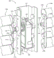
Referring to fig. 1-4, the present disclosure is directed to a serviceable actuation arrangement 10 for an active grille shutter system 12. The serviceable actuation device 10 includes a linkage 14, wherein the linkage 14 has vertical link arms 16, 18 spaced apart by a bridge 20. The bridge 20 has a clearance opening 22 defined by a curved surface 24 of the bridge 20. The gap opening 22 includes a first securement arm 26 defining a first side of the gap opening 22 and a second securement arm 28 defining a second side of the gap opening 22. First securement arm 26 and second securement arm 28 each have an aperture 30, 32.
The two vertical link arms 16, 18 of the linkage 14 include a plurality of vane connection posts 34, 34 'connected to apertures 33, 33' on vanes 35a, 35, the vanes 35a, 35 being shown as two sets of vanes with a left set of vanes 35a and a right set of vanes 35 b. The blade connection posts 34, 34 'may be circular protrusions or any type of protrusion capable of sliding into and connecting to the blade members in a manner that allows the blades 35 to rotate about the plurality of connection posts 34, 34'. Furthermore, according to the application, apertures are formed on both vertical link arms and posts are formed on the blade connected to the apertures on the vertical link arms. The serviceable actuation device 10 also includes an actuator 36 positioned between the first and second retaining arms 26, 28 within the clearance opening 22. The actuator 36 includes first and second drive connections 38, 40, the first and second drive connections 38, 40 being apertures through a housing 42 of the actuator 36 that provide access for the rotational force transmitting elements. An example of a rotational force element is a hexagonal rotary gear coupled to the motor and located within the first drive connection 38 and the second drive connection 40.
The serviceable actuation device 10 also includes a first drive arm 44 positioned between the actuator 36 and the first stationary arm 26. A first drive arm 44 is rotatably connected to the first drive connection 38, and the first removable arm 44 also has a pivot aperture 46 aligned with the aperture 30 of the first fixed arm 26. There is also a second drive arm 48 between the actuator 36 and the second fixed arm 28. The second drive arm 48 is rotatably connected to the second drive connection 40 of the actuator 36. The second removable arm 48 also has a pivot aperture 50 that is aligned with the aperture 32 of the second stationary arm 28.
The serviceable actuation device 10 also includes a clamp 52, the clamp 52 having a pivot rod 54 connected to the bridge 20 of the linkage 14. The connection between the clip 52 and the bridge 20 of the linkage 14 is a snap-fit connection 53, which snap-fit connection 53 allows the pivot rod 54 of the clip 52 to rotate relative to the bridge 20. The clamp 52 includes two parallel arcuate arches including a first parallel arcuate arch 64 and a second parallel arcuate arch 66 that extend parallel to each other from opposite ends of the pivot rod 54. The first pivot post 56 extends from an end of the first parallel arcuate arch 64 toward the second parallel arcuate arch 66. The first pivot post 56 pivotally extends through both the aperture 30 of the first stationary arm 26 and the pivot aperture 46 of the first drive arm 44. There is also a second pivot post 58 extending from the second parallel arcuate arch 66. The second pivot post 58 pivotally extends through both the aperture 32 of the second stationary arm 28 and the pivot aperture 50 of the second drive arm 48 toward the first parallel arcuate arch 64.
According to the invention, neither of the blades 35a, 35b is driven by the linkage 14 which is not directly connected to the actuator 36. The linkage 14 is connected to the actuator 36 via a connector clamp 52, the first drive arm 44 and the second drive arm 48, which connector clamp 52, the first drive arm 44 and the second drive arm 48 can be disassembled to allow the actuator 36 to be removed without having to disassemble the blade from the linkage 14 or disconnect the blade from the linkage 14.
Fig. 1-4 depict how the actuator 36 is removed. In fig. 1, the actuator 36 is connected to the linkage 14 and is held in place by a clip 52, the clip 52 being held in place against rotation by a pivot rod 54 by means of a snap-fit connection 53 formed on the bridge 20. Also shown are retainer fingers 60, 62 that extend from first and second retaining arms 26, 28 and also assist in securing grip 52 by pressing two parallel arcuate arches 64, 66 inward. Retainer fingers 60, 62 are optional features and are not necessary for all embodiments of the present invention. In fig. 2, the pivot rod 54 has been released from the snap-fit connection 52 and the two parallel arcuate arches 64, 66 have been released from the retainer fingers 60, 62; allowing clip 52 to rotate downward relative to fig. 2. When the clamp 52 is released, the parallel arcuate arches 64, 66 may flex outwardly toward each other to pull the first and second pivot posts 56, 58 out of the apertures 30, 32 of the first and second stationary arms 26, 28 and the respective pivot apertures 46, 50 of the respective first and second drive arms 44, 48. Fig. 3 shows the actuator 36 removed from the linkage 14 once the clip 52 is removed. The linkage 14 is decoupled from the actuator 36 so the actuator 36 can be removed without disassembling any other components within the active grille shutter system 12. The actuator 36 may be further disassembled as shown in fig. 4. The male connector 45 of the first drive arm 44 slides out of the female connector of the actuator 36. Likewise, the male connector 45 'of the second drive arm 48 slides out of the female connector 43' of the actuator 36.
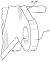
Referring now to fig. 9 and 10, two additional variations of the first or second securing arm 28 are shown. Fig. 9 depicts a first or second securement arm 26 ', 28' having a thickness 27 'surrounding apertures 30', 32 ', which thickness 27' is lower or thinner in profile when compared to the thickness 27 of the variation shown in fig. 10. The low profile provides clearance and packaging advantages to the area of securing arms 26 ', 28'. However, the low profile presents manufacturing disadvantages that require the mold tooling used to form the linkage 14 to have the action characteristics required to eject the linkage 14 from the mold. The variation shown in fig. 10 depicts the securing arm 26 or second securing arm 28 having two opposing U-shaped bends 29, 31 that allow the resulting linkage 14 to be removed from the tooling without requiring action in the tooling.
Referring now to fig. 5-8, an alternative embodiment of a serviceable actuation device 100 is shown. The serviceable actuation arrangement includes a frame portion 112 of the active grille shutter system. The frame portion 112 is depicted as a center bar of the active grille shutter system, however, it is within the scope of the present invention that the frame portion 112 may be a different portion of the frame, such as a side bar, a top bar, a bottom bar, or nearly another portion of the frame of the active grille shutter system. The frame portion 112 includes an actuator seat section 114 having a base 116, the base 116 having an aperture 118 through the base 116. There are also two opposing side walls 120a, 120b, each of the two opposing side walls 120a, 120b having an inner surface 122a, 122b facing inwardly to form a wall of the actuator seat section 114. The opposing sidewalls 120a, 120b also have outer surfaces 124a, 124 b. The opposing sidewalls 120a, 120b have a plurality of blade apertures 126, 126' extending from the respective inner surfaces 122a, 122b through to the outer surfaces 124a, 124 b. The vane apertures 126, 126' are configured to receive respective posts 127a, 127b on one of the plurality of driven vanes 130a, 130 b. As shown, there are six follower vanes 130a, 130b, the six follower vanes 130a, 130b being shown as a left-hand set of vanes and a right-hand set of vanes, wherein the terms left and right are relative to the frame portion 112 shown in fig. 5. Although six driven vanes are shown, it is within the scope of the present invention that there be a greater or lesser number of driven vanes as desired for a particular application. Each set of blades also includes a drive blade 131a, 131b, which drive blades 131a, 131b are driven by an actuator 144 through various linkages as will be discussed in more detail below. Each left and right group includes a link 132a, 132b connected to the respective driving blade 131a, 131b and driven blade 130a, 130 b. The links 132a, 132b serve to transmit the rotational force from the respective driving blades 131a, 131b to the driven blades 130a, 130 b.
The opposing sidewalls 120a, 120b each have a drive aperture 128, 128 ', wherein the drive elements 134a, 134b rotatably extend through the drive apertures 128, 128'. In this embodiment of the invention, the drive elements 134, 134 'are formed by the drive apertures 128, 128' in the same mold using a two-shot molding process, so that no additional assembly steps are required. Each drive element 134a, 134b has a first end 136, 136 'located within the actuator seating section 114, and a second end 140, 140' of the drive element 134a, 134b is located outside of the frame portion 112.
The actuator 144 has a housing 146 with drive shafts 148, 148' extending from the housing 146. Each of the drive shafts 148, 148' is configured for bi-directional drive and is powered by a motor (not shown) located within the housing 146. The first end 136, 136 'of the drive element has a slot 139, 139', the slot 139, 139 'has an open edge 138, 138', the open edge 138, 138 'allowing the respective drive shaft 148, 148' to slide into the slot 139, 139 'through the open edge 138, 138', such that the drive element 134a, 134b is driven bi-directionally by the actuator 144.
The actuator 144 housing 146 also includes a seating surface 150 configured to contact against the base 116. A connector 152 extends from the seating surface 150 of the actuator housing 146 and provides a port for powering and controlling movement of the motor of the actuator 144. When the actuator 144 is seated in the actuator seating section 114, the connector 152 extends through the aperture 118 of the base 116.
In order to align the drive shafts 148, 148' with the drive elements 134a, 134b, a positioning post 154 is provided above the base 116. The locating post has an aperture 156, the aperture 156 being threaded to receive a fastener 162 that holds the actuator 144 in place. The fasteners 162 are positioned through apertures 160 formed on a flange 158 extending from the top surface of the housing 146. Although fasteners and threaded connections are shown, it is within the scope of the invention for the locating post 154 and flange 158 to have snap tabs or mechanical clip connections.
Referring now to fig. 11, another alternative embodiment of a serviceable actuation device 200 is shown with a separate drive element. The embodiment shown in fig. 11 has a similar structure to that shown in fig. 5 to 8 and therefore the same reference numerals will be used, while different or new structures will be labelled with new reference numerals. The serviceable actuator 200 includes a frame portion 112 of an active grille shutter system. Two opposing side walls 120a, 120b each have an inward facing inner surface 122a, 122b to form a wall of the actuator seat section 114. The opposing sidewalls 120a, 120b also have outer surfaces 124a, 124 b. The opposing sidewalls 120a, 120b have a plurality of blade apertures 126, 126 ', the plurality of blade apertures 126, 126' extending through from the respective inner surfaces 122a, 122b to the outer surfaces 124a, 124b and serving as mounting holes for the rotor blades, as described above with reference to fig. 5-8.
The opposing sidewalls 120a, 120b each have a drive aperture 128, 128 ', the drive apertures 128, 128 ' being configured to receive a drive element 234a, 234b that rotatably extends through the drive apertures 128, 128 '. The drive elements 234a, 234b in fig. 11 differ from the drive elements 134a, 134b in fig. 8 in that the drive elements 234a, 234b are separate pieces that are pushed into place through each respective drive aperture 128, 128' rather than being formed in the same mold as the frame portion 112 using a two-shot molding process. This embodiment also allows the actuator 144 to be connected to the actuator seating section 114 before connecting the drive elements 234a, 234 b. When the drive elements 234a, 234b are positioned through the respective drive apertures 128, 128 ', the first ends 236, 236 ' of the drive elements 134a, 134b will be located within the actuator seating section 114, while the second ends 140, 140 ' of the drive elements 134a, 134b are located outside of the frame portion 112.
The actuator 144 drive shafts 148, 148 'are configured to connect with first ends 236, 236' of the drive elements 234a, 234 b. Proximate the first end 236, 236 'is a slot 239, 239', the slot 239, 239 'having an open edge 238, 238', the open edge 238, 238 'allowing the respective drive shaft 148, 148' to slide into the slot 239, 239 'through the open edge 238, 238', such that the drive element 234a, 234b is bi-directionally driven by the actuator 144.
Fig. 12 is an alternative embodiment of a serviceable actuator 300 having a structure similar to that shown in fig. 5-8 and 11, and therefore will use the same reference numbers, while different or new structures will be labeled with new reference numbers. The serviceable actuation device 300 includes the frame portion 112 of the active grille shutter system. Two opposing side walls 120a, 120b each have an inward facing inner surface 122a, 122b to form a wall of the actuator seat section 114. The opposing sidewalls 120a, 120b also have outer surfaces 124a, 124 b. The opposing sidewalls 120a, 120b have a plurality of blade apertures 126, 126 ', the plurality of blade apertures 126, 126' extending from the respective inner surfaces 122a, 122b through to the outer surfaces 124a, 124b and serving as mounting holes for the rotor blades, as described above with reference to fig. 5-8.
The opposing sidewalls 120a, 120b each have a drive aperture 128, 128 ', the drive apertures 128, 128 ' being configured to receive a drive element 334a, 334b that rotatably extends through the drive apertures 128, 128 '. The drive elements 334a, 334b of fig. 12 differ from the drive elements 234a, 234b of fig. 11 in that the drive elements 334a, 334b are integral with the drive blades 331a, 331b, rather than being separate pieces. The joining of the driver blades 331a, 331b is accomplished in a number of ways, such as injection molding, welding, or using an adhesive. When the drive elements 334a, 334b are positioned through the respective drive apertures 128, 128 ', the first ends 336, 336 ' of the drive elements 334a, 334b will be located within the actuator seat section 114, while the second ends 340, 340 ' of the drive elements 334a, 334b are located outside of the frame portion 112.
The actuator 144 drive shafts 148, 148 'are configured to connect with first ends 336, 336' of the drive elements 334a, 334 b. Proximate the first ends 336, 336 'are slots 339, 339', the slots 339, 339 'having open edges 338, 338', the open edges 338, 338 'allowing the respective drive shafts 148, 148' to slide into the slots 339, 339 'through the open edges 338, 338' such that the drive elements 334a, 334b are bi-directionally driven by the actuator 144.
Those skilled in the art can now appreciate from the foregoing description: the broad teachings of the present disclosure can be implemented in a variety of forms. Therefore, while this invention has been described in connection with particular examples thereof, the true scope of the invention should not be so limited since other modifications will become apparent to the skilled practitioner upon a study of the drawings, the specification and the following claims.
Claims (12)
1. A serviceable actuation arrangement for an active grille shutter system comprising:
a linkage having two vertical link arms spaced apart by a bridge;
an actuator connected to the bridge, wherein the actuator moves the linkage between a first position and a second position;
a first drive arm having a pivot aperture positioned between the actuator and the bridge;
a second drive arm having a pivot aperture positioned between the actuator and the bridge; and
a connector clip having a first pivot post extending through the bridge portion and the pivot aperture of the first drive arm and a second pivot post extending through the bridge portion and the pivot aperture of the second drive arm, wherein the connector clip has two parallel arcuate arches connected together at one end by a pivot rod,
wherein the pivot lever is rotatably connected to the bridge portion using a snap-fit tab formed on the bridge portion, and the first pivot post extends from a first of the two arches and the second pivot post extends from a second of the two arches, such that the connector clip is rotatable about the first and second pivot posts when the pivot lever is disconnected from the snap-fit tab of the bridge portion.
2. The serviceable actuation device of claim 1, further comprising a clearance opening of the bridge that prevents the bridge from contacting the actuator as the linkage moves.
3. A serviceable actuation arrangement for an active grille shutter system comprising:
a linkage having two vertical link arms spaced apart by a bridge;
an actuator connected to the bridge, wherein the actuator moves the linkage between a first position and a second position;
a first drive arm having a pivot aperture positioned between the actuator and the bridge;
a second drive arm having a pivot aperture positioned between the actuator and the bridge;
a connector clip having a first pivot post extending through the bridge portion and the pivot aperture of the first drive arm and a second pivot post extending through the bridge portion and the pivot aperture of the second drive arm; and
a first securement arm located on the bridge and extending toward the actuator, and a second securement arm located on the bridge and extending toward the actuator,
wherein the first stationary arm has an aperture and the second stationary arm has an aperture and the first pivot post of the connector clamp extends through both the aperture of the first stationary arm and the pivot aperture of the first drive arm and the second pivot post of the connector clamp extends through both the aperture of the second stationary arm and the pivot aperture of the second drive arm.
4. The serviceable actuation device of claim 3, further comprising:
a first half U-shaped flange on a first side of said first retaining arm and a second half U-shaped flange on a second side of said first retaining arm to assist in the formation of an aperture of said first retaining arm, thereby eliminating the need for additional tools;
a first half U-shaped flange on a first side of said second retaining arm and a second half U-shaped flange on a second side of said second retaining arm to assist in the formation of an aperture of said second retaining arm, thereby eliminating the need for additional tools.
5. The serviceable actuation device of claim 3, further comprising a retainer finger extending from the first and second securement arms for aligning and retaining the first and second pivot posts through the apertures of the respective first and second securement arms.
6. The serviceable actuation device of claim 1, further comprising:
a plurality of vane pivot posts formed on the two vertical link arms;
a plurality of vanes of an active grille shutter system, wherein each of the plurality of vanes is connected to a respective one of the plurality of vane pivot posts.
7. A serviceable actuation arrangement for an active grille shutter system comprising:
a linkage having two vertical link arms spaced apart by a bridge, a first fixed arm, and a second fixed arm, wherein the first fixed arm and the second fixed arm each have an aperture;
a plurality of vane connection posts located on each of the two vertical linkage arms;
an actuator positioned between the first and second fixed arms, the actuator including a first drive link and a second drive link;
a first drive arm positioned between the actuator and the first stationary arm, wherein the first drive arm is rotatably connected to the first drive link and has a pivot aperture aligned with the aperture of the first stationary arm;
a second drive arm positioned between the actuator and the second stationary arm, wherein the second drive arm is rotatably connected to the second drive link and has a pivot aperture aligned with the aperture of the second stationary arm; and
a connector clip having a pivot rod pivotally connected to the bridge portion of the linkage, and having a first pivot post pivotally extending through both the aperture of the first fixed arm and the pivot aperture of the first drive arm and a second pivot post pivotally extending through both the aperture of the second fixed arm and the pivot aperture of the second drive arm.
8. The serviceable actuation device of claim 7, wherein the connector clip has two parallel arcuate arches connected together at one end by a pivot rod, wherein the pivot rod is rotatably connected to the bridge using a snap-fit tab formed on the bridge, and the first pivot post extends from a first of the two arches and the second pivot post extends from a second of the two arches such that the connector clip can rotate about the first and second pivot posts when the pivot rod is disconnected from the snap-fit tab of the bridge.
9. The serviceable actuation device of claim 7, further comprising a clearance opening of the bridge that prevents the bridge from contacting the actuator as the linkage moves.
10. The serviceable actuation device of claim 7, further comprising:
a first half U-shaped flange on a first side of said first retaining arm and a second half U-shaped flange on a second side of said first retaining arm to assist in the formation of an aperture of said first retaining arm, thereby eliminating the need for additional tools;
a first half U-shaped flange on a first side of said second retaining arm and a second half U-shaped flange on a second side of said second retaining arm to assist in the formation of an aperture of said second retaining arm, thereby eliminating the need for additional tools.
11. The serviceable actuation device of claim 7, further comprising:
a plurality of vane pivot posts formed on the two vertical link arms;
a plurality of vanes of an active grille shutter system, wherein each of the plurality of vanes is connected to a respective one of the plurality of vane pivot posts.
12. The serviceable actuation device of claim 7, further comprising a retainer finger extending from the first and second securement arms for aligning and retaining the first and second pivot posts through the apertures of the respective first and second securement arms.
Applications Claiming Priority (3)
| Application Number | Priority Date | Filing Date | Title |
|---|---|---|---|
| US201862680687P | 2018-06-05 | 2018-06-05 | |
| US62/680,687 | 2018-06-05 | ||
| PCT/US2019/029678 WO2019236212A1 (en) | 2018-06-05 | 2019-04-29 | Serviceable actuation system for active grille shutter |
Publications (2)
| Publication Number | Publication Date |
|---|---|
| CN112351902A CN112351902A (en) | 2021-02-09 |
| CN112351902B true CN112351902B (en) | 2022-02-25 |
Family
ID=66429713
Family Applications (1)
| Application Number | Title | Priority Date | Filing Date |
|---|---|---|---|
| CN201980038162.5A Active CN112351902B (en) | 2018-06-05 | 2019-04-29 | Serviceable actuation system for an active grille shutter |
Country Status (6)
| Country | Link |
|---|---|
| US (1) | US11230879B2 (en) |
| EP (1) | EP3802187A1 (en) |
| KR (1) | KR102215402B1 (en) |
| CN (1) | CN112351902B (en) |
| CA (1) | CA3102589C (en) |
| WO (1) | WO2019236212A1 (en) |
Families Citing this family (2)
| Publication number | Priority date | Publication date | Assignee | Title |
|---|---|---|---|---|
| US11230879B2 (en) * | 2018-06-05 | 2022-01-25 | Magna Exteriors, Inc | Serviceable actuation system for active grille shutter |
| KR20220034608A (en) * | 2020-09-11 | 2022-03-18 | 현대모비스 주식회사 | Active Air Flap Apparatus For Vehicle |
Citations (3)
| Publication number | Priority date | Publication date | Assignee | Title |
|---|---|---|---|---|
| WO2014083430A2 (en) * | 2012-10-03 | 2014-06-05 | Magna International Inc. | Spring-operated back-up/fail-safe module for active grille shutter systems |
| WO2016087567A1 (en) * | 2014-12-03 | 2016-06-09 | Hbpo Gmbh | Optimized air control system for vehicles |
| CN107878183A (en) * | 2017-11-29 | 2018-04-06 | 宁波海德欣汽车电器有限公司 | A kind of automotive air intake amount governor motion |
Family Cites Families (18)
| Publication number | Priority date | Publication date | Assignee | Title |
|---|---|---|---|---|
| GB2082520B (en) | 1980-08-28 | 1983-12-07 | Talbot Motor | Cooling of vehicle engines |
| JP2010223150A (en) * | 2009-03-25 | 2010-10-07 | Aisin Seiki Co Ltd | Movable grille shutter for vehicle |
| US8561739B2 (en) * | 2010-07-13 | 2013-10-22 | Aisin Seiki Kabushiki Kaisha | Movable grille shutter for vehicle |
| KR101272912B1 (en) * | 2010-11-10 | 2013-06-11 | 현대자동차주식회사 | Active air flap apparatus |
| KR101261516B1 (en) | 2011-04-06 | 2013-05-06 | 토마토에이엔피(주) | A radiator grill comprising air flap |
| CH706456B1 (en) * | 2012-04-30 | 2016-03-15 | Schwanden Kunststoff | Jalousie for placement in front of a radiator. |
| WO2014205217A1 (en) * | 2013-06-19 | 2014-12-24 | Magna International Inc. | Sealed actuator with internal clutching |
| KR102470561B1 (en) * | 2014-06-11 | 2022-11-25 | 마그나 익스테리어즈 인크. | Active front deflector |
| EP3002145B1 (en) * | 2014-09-30 | 2017-10-18 | Faltec Company Limited | Vehicle grill shutter, vehicle flap member, and actuator |
| EP3199395B1 (en) | 2016-01-29 | 2018-09-19 | Batz, S.Coop. | Shutter device for a front grille of a vehicle |
| DE102016209156A1 (en) * | 2016-05-25 | 2017-11-30 | Magna Exteriors Gmbh | Flap system for the control of vehicle cooling |
| US10960754B2 (en) * | 2016-08-12 | 2021-03-30 | Magna Exteriors, Inc. | Mold assembly for active grille shutter system |
| WO2019073422A1 (en) * | 2017-10-10 | 2019-04-18 | Magna Exteriors Inc. | Active aero system in-mold assembly hinge modular frame |
| WO2018029655A1 (en) * | 2016-08-12 | 2018-02-15 | Magna Exteriors Inc | Active grille, scalable design |
| FR3058367B1 (en) | 2016-11-09 | 2018-12-07 | Valeo Systemes Thermiques | SHUT OFF DEVICE FOR FRONT PANEL FRONT AIR INTAKE OF MOTOR VEHICLE |
| CA3084676C (en) * | 2018-01-30 | 2022-11-01 | Magna Exteriors Inc. | Linkage for improved diagnostics and kinematic assembly |
| FR3078505B1 (en) * | 2018-03-02 | 2020-06-26 | Valeo Systemes Thermiques | SHUTTER UNIT FOR MOTOR VEHICLE SEALING DEVICE |
| US11230879B2 (en) * | 2018-06-05 | 2022-01-25 | Magna Exteriors, Inc | Serviceable actuation system for active grille shutter |
-
2019
- 2019-04-29 US US15/734,853 patent/US11230879B2/en active Active
- 2019-04-29 CN CN201980038162.5A patent/CN112351902B/en active Active
- 2019-04-29 WO PCT/US2019/029678 patent/WO2019236212A1/en unknown
- 2019-04-29 EP EP19722492.6A patent/EP3802187A1/en active Pending
- 2019-04-29 KR KR1020207037904A patent/KR102215402B1/en active IP Right Grant
- 2019-04-29 CA CA3102589A patent/CA3102589C/en active Active
Patent Citations (3)
| Publication number | Priority date | Publication date | Assignee | Title |
|---|---|---|---|---|
| WO2014083430A2 (en) * | 2012-10-03 | 2014-06-05 | Magna International Inc. | Spring-operated back-up/fail-safe module for active grille shutter systems |
| WO2016087567A1 (en) * | 2014-12-03 | 2016-06-09 | Hbpo Gmbh | Optimized air control system for vehicles |
| CN107878183A (en) * | 2017-11-29 | 2018-04-06 | 宁波海德欣汽车电器有限公司 | A kind of automotive air intake amount governor motion |
Also Published As
| Publication number | Publication date |
|---|---|
| KR102215402B1 (en) | 2021-02-10 |
| KR20210009385A (en) | 2021-01-26 |
| US11230879B2 (en) | 2022-01-25 |
| CA3102589A1 (en) | 2019-12-12 |
| EP3802187A1 (en) | 2021-04-14 |
| CN112351902A (en) | 2021-02-09 |
| US20210230936A1 (en) | 2021-07-29 |
| WO2019236212A1 (en) | 2019-12-12 |
| CA3102589C (en) | 2021-03-30 |
Similar Documents
| Publication | Publication Date | Title |
|---|---|---|
| CN112351902B (en) | Serviceable actuation system for an active grille shutter | |
| CN109564024B (en) | Expandable design of active grille | |
| JP4547333B2 (en) | Device and method for releasably connecting a wiper blade to a drivable wiper arm | |
| CN114136001B (en) | air conditioner | |
| US9845074B2 (en) | Wiper blade | |
| EP3119635B1 (en) | Hollow vane with structure | |
| EP3399195A1 (en) | Impeller for centrifugal fan, and method and device for manufacturing same | |
| RU2604912C2 (en) | Windscreen wiper related adapter, primarily for automotive wiper | |
| JP2010195397A (en) | Assembly of wiper blade, and assembly of wiper | |
| EP2813403B1 (en) | Wiper system | |
| CN114245778A (en) | Multiple wiper blade adapters for wiper blade assemblies | |
| JP6813686B2 (en) | Ball joint with locking ball socket assembly | |
| EP0354279A1 (en) | Wipers for windscreens and like surfaces | |
| EP4054873B1 (en) | Modular aero device actuator and a modular active grille shutter system having a reduced number of vanes | |
| KR100373479B1 (en) | Drive hub and transverse fan assembly | |
| CN210292243U (en) | Louver structure and air outlet device | |
| US10920814B2 (en) | Bracket for mounting an actuator to an actuatable component | |
| CN106917779B (en) | Water discharge pump | |
| JP2013500426A (en) | Guide structure for mixed-flow fan coupling | |
| KR102494626B1 (en) | Hybrid Windshield Wiper Blades | |
| KR20000048019A (en) | Transverse fan motor drive coupling | |
| CN219806695U (en) | Rotary adapter, push-pull structure, active air inlet grille and vehicle | |
| US11738718B2 (en) | Adapter for a wiper blade mounting of a motor vehicle | |
| CN219883672U (en) | Moving structure, active air inlet grille and vehicle | |
| WO2019199404A1 (en) | Multiple position locking wiper arm connector |
Legal Events
| Date | Code | Title | Description |
|---|---|---|---|
| PB01 | Publication | ||
| PB01 | Publication | ||
| SE01 | Entry into force of request for substantive examination | ||
| SE01 | Entry into force of request for substantive examination | ||
| GR01 | Patent grant | ||
| GR01 | Patent grant |