CN112334970B - Source side tone mapping based on native gamut and brightness of a display - Google Patents
Source side tone mapping based on native gamut and brightness of a display Download PDFInfo
- Publication number
- CN112334970B CN112334970B CN201980043311.7A CN201980043311A CN112334970B CN 112334970 B CN112334970 B CN 112334970B CN 201980043311 A CN201980043311 A CN 201980043311A CN 112334970 B CN112334970 B CN 112334970B
- Authority
- CN
- China
- Prior art keywords
- display
- display image
- native
- monitor
- tone
- Prior art date
- Legal status (The legal status is an assumption and is not a legal conclusion. Google has not performed a legal analysis and makes no representation as to the accuracy of the status listed.)
- Active
Links
Images


Classifications
-
- G—PHYSICS
- G09—EDUCATION; CRYPTOGRAPHY; DISPLAY; ADVERTISING; SEALS
- G09G—ARRANGEMENTS OR CIRCUITS FOR CONTROL OF INDICATING DEVICES USING STATIC MEANS TO PRESENT VARIABLE INFORMATION
- G09G5/00—Control arrangements or circuits for visual indicators common to cathode-ray tube indicators and other visual indicators
- G09G5/02—Control arrangements or circuits for visual indicators common to cathode-ray tube indicators and other visual indicators characterised by the way in which colour is displayed
- G09G5/04—Control arrangements or circuits for visual indicators common to cathode-ray tube indicators and other visual indicators characterised by the way in which colour is displayed using circuits for interfacing with colour displays
-
- G—PHYSICS
- G06—COMPUTING; CALCULATING OR COUNTING
- G06F—ELECTRIC DIGITAL DATA PROCESSING
- G06F3/00—Input arrangements for transferring data to be processed into a form capable of being handled by the computer; Output arrangements for transferring data from processing unit to output unit, e.g. interface arrangements
- G06F3/14—Digital output to display device ; Cooperation and interconnection of the display device with other functional units
- G06F3/147—Digital output to display device ; Cooperation and interconnection of the display device with other functional units using display panels
-
- G—PHYSICS
- G09—EDUCATION; CRYPTOGRAPHY; DISPLAY; ADVERTISING; SEALS
- G09G—ARRANGEMENTS OR CIRCUITS FOR CONTROL OF INDICATING DEVICES USING STATIC MEANS TO PRESENT VARIABLE INFORMATION
- G09G3/00—Control arrangements or circuits, of interest only in connection with visual indicators other than cathode-ray tubes
- G09G3/20—Control arrangements or circuits, of interest only in connection with visual indicators other than cathode-ray tubes for presentation of an assembly of a number of characters, e.g. a page, by composing the assembly by combination of individual elements arranged in a matrix no fixed position being assigned to or needed to be assigned to the individual characters or partial characters
- G09G3/2003—Display of colours
-
- G—PHYSICS
- G09—EDUCATION; CRYPTOGRAPHY; DISPLAY; ADVERTISING; SEALS
- G09G—ARRANGEMENTS OR CIRCUITS FOR CONTROL OF INDICATING DEVICES USING STATIC MEANS TO PRESENT VARIABLE INFORMATION
- G09G3/00—Control arrangements or circuits, of interest only in connection with visual indicators other than cathode-ray tubes
- G09G3/20—Control arrangements or circuits, of interest only in connection with visual indicators other than cathode-ray tubes for presentation of an assembly of a number of characters, e.g. a page, by composing the assembly by combination of individual elements arranged in a matrix no fixed position being assigned to or needed to be assigned to the individual characters or partial characters
- G09G3/2007—Display of intermediate tones
-
- G—PHYSICS
- G09—EDUCATION; CRYPTOGRAPHY; DISPLAY; ADVERTISING; SEALS
- G09G—ARRANGEMENTS OR CIRCUITS FOR CONTROL OF INDICATING DEVICES USING STATIC MEANS TO PRESENT VARIABLE INFORMATION
- G09G3/00—Control arrangements or circuits, of interest only in connection with visual indicators other than cathode-ray tubes
- G09G3/20—Control arrangements or circuits, of interest only in connection with visual indicators other than cathode-ray tubes for presentation of an assembly of a number of characters, e.g. a page, by composing the assembly by combination of individual elements arranged in a matrix no fixed position being assigned to or needed to be assigned to the individual characters or partial characters
- G09G3/2092—Details of a display terminals using a flat panel, the details relating to the control arrangement of the display terminal and to the interfaces thereto
- G09G3/2096—Details of the interface to the display terminal specific for a flat panel
-
- G—PHYSICS
- G09—EDUCATION; CRYPTOGRAPHY; DISPLAY; ADVERTISING; SEALS
- G09G—ARRANGEMENTS OR CIRCUITS FOR CONTROL OF INDICATING DEVICES USING STATIC MEANS TO PRESENT VARIABLE INFORMATION
- G09G3/00—Control arrangements or circuits, of interest only in connection with visual indicators other than cathode-ray tubes
- G09G3/20—Control arrangements or circuits, of interest only in connection with visual indicators other than cathode-ray tubes for presentation of an assembly of a number of characters, e.g. a page, by composing the assembly by combination of individual elements arranged in a matrix no fixed position being assigned to or needed to be assigned to the individual characters or partial characters
- G09G3/34—Control arrangements or circuits, of interest only in connection with visual indicators other than cathode-ray tubes for presentation of an assembly of a number of characters, e.g. a page, by composing the assembly by combination of individual elements arranged in a matrix no fixed position being assigned to or needed to be assigned to the individual characters or partial characters by control of light from an independent source
- G09G3/3406—Control of illumination source
- G09G3/342—Control of illumination source using several illumination sources separately controlled corresponding to different display panel areas, e.g. along one dimension such as lines
- G09G3/3426—Control of illumination source using several illumination sources separately controlled corresponding to different display panel areas, e.g. along one dimension such as lines the different display panel areas being distributed in two dimensions, e.g. matrix
-
- G—PHYSICS
- G09—EDUCATION; CRYPTOGRAPHY; DISPLAY; ADVERTISING; SEALS
- G09G—ARRANGEMENTS OR CIRCUITS FOR CONTROL OF INDICATING DEVICES USING STATIC MEANS TO PRESENT VARIABLE INFORMATION
- G09G3/00—Control arrangements or circuits, of interest only in connection with visual indicators other than cathode-ray tubes
- G09G3/20—Control arrangements or circuits, of interest only in connection with visual indicators other than cathode-ray tubes for presentation of an assembly of a number of characters, e.g. a page, by composing the assembly by combination of individual elements arranged in a matrix no fixed position being assigned to or needed to be assigned to the individual characters or partial characters
- G09G3/34—Control arrangements or circuits, of interest only in connection with visual indicators other than cathode-ray tubes for presentation of an assembly of a number of characters, e.g. a page, by composing the assembly by combination of individual elements arranged in a matrix no fixed position being assigned to or needed to be assigned to the individual characters or partial characters by control of light from an independent source
- G09G3/36—Control arrangements or circuits, of interest only in connection with visual indicators other than cathode-ray tubes for presentation of an assembly of a number of characters, e.g. a page, by composing the assembly by combination of individual elements arranged in a matrix no fixed position being assigned to or needed to be assigned to the individual characters or partial characters by control of light from an independent source using liquid crystals
-
- G—PHYSICS
- G09—EDUCATION; CRYPTOGRAPHY; DISPLAY; ADVERTISING; SEALS
- G09G—ARRANGEMENTS OR CIRCUITS FOR CONTROL OF INDICATING DEVICES USING STATIC MEANS TO PRESENT VARIABLE INFORMATION
- G09G5/00—Control arrangements or circuits for visual indicators common to cathode-ray tube indicators and other visual indicators
- G09G5/003—Details of a display terminal, the details relating to the control arrangement of the display terminal and to the interfaces thereto
- G09G5/005—Adapting incoming signals to the display format of the display terminal
-
- G—PHYSICS
- G09—EDUCATION; CRYPTOGRAPHY; DISPLAY; ADVERTISING; SEALS
- G09G—ARRANGEMENTS OR CIRCUITS FOR CONTROL OF INDICATING DEVICES USING STATIC MEANS TO PRESENT VARIABLE INFORMATION
- G09G5/00—Control arrangements or circuits for visual indicators common to cathode-ray tube indicators and other visual indicators
- G09G5/10—Intensity circuits
-
- G—PHYSICS
- G09—EDUCATION; CRYPTOGRAPHY; DISPLAY; ADVERTISING; SEALS
- G09G—ARRANGEMENTS OR CIRCUITS FOR CONTROL OF INDICATING DEVICES USING STATIC MEANS TO PRESENT VARIABLE INFORMATION
- G09G5/00—Control arrangements or circuits for visual indicators common to cathode-ray tube indicators and other visual indicators
- G09G5/36—Control arrangements or circuits for visual indicators common to cathode-ray tube indicators and other visual indicators characterised by the display of a graphic pattern, e.g. using an all-points-addressable [APA] memory
- G09G5/363—Graphics controllers
-
- G—PHYSICS
- G09—EDUCATION; CRYPTOGRAPHY; DISPLAY; ADVERTISING; SEALS
- G09G—ARRANGEMENTS OR CIRCUITS FOR CONTROL OF INDICATING DEVICES USING STATIC MEANS TO PRESENT VARIABLE INFORMATION
- G09G2320/00—Control of display operating conditions
- G09G2320/02—Improving the quality of display appearance
- G09G2320/0271—Adjustment of the gradation levels within the range of the gradation scale, e.g. by redistribution or clipping
-
- G—PHYSICS
- G09—EDUCATION; CRYPTOGRAPHY; DISPLAY; ADVERTISING; SEALS
- G09G—ARRANGEMENTS OR CIRCUITS FOR CONTROL OF INDICATING DEVICES USING STATIC MEANS TO PRESENT VARIABLE INFORMATION
- G09G2320/00—Control of display operating conditions
- G09G2320/06—Adjustment of display parameters
- G09G2320/0626—Adjustment of display parameters for control of overall brightness
- G09G2320/0646—Modulation of illumination source brightness and image signal correlated to each other
-
- G—PHYSICS
- G09—EDUCATION; CRYPTOGRAPHY; DISPLAY; ADVERTISING; SEALS
- G09G—ARRANGEMENTS OR CIRCUITS FOR CONTROL OF INDICATING DEVICES USING STATIC MEANS TO PRESENT VARIABLE INFORMATION
- G09G2320/00—Control of display operating conditions
- G09G2320/06—Adjustment of display parameters
- G09G2320/0666—Adjustment of display parameters for control of colour parameters, e.g. colour temperature
-
- G—PHYSICS
- G09—EDUCATION; CRYPTOGRAPHY; DISPLAY; ADVERTISING; SEALS
- G09G—ARRANGEMENTS OR CIRCUITS FOR CONTROL OF INDICATING DEVICES USING STATIC MEANS TO PRESENT VARIABLE INFORMATION
- G09G2320/00—Control of display operating conditions
- G09G2320/06—Adjustment of display parameters
- G09G2320/0673—Adjustment of display parameters for control of gamma adjustment, e.g. selecting another gamma curve
-
- G—PHYSICS
- G09—EDUCATION; CRYPTOGRAPHY; DISPLAY; ADVERTISING; SEALS
- G09G—ARRANGEMENTS OR CIRCUITS FOR CONTROL OF INDICATING DEVICES USING STATIC MEANS TO PRESENT VARIABLE INFORMATION
- G09G2340/00—Aspects of display data processing
- G09G2340/06—Colour space transformation
-
- G—PHYSICS
- G09—EDUCATION; CRYPTOGRAPHY; DISPLAY; ADVERTISING; SEALS
- G09G—ARRANGEMENTS OR CIRCUITS FOR CONTROL OF INDICATING DEVICES USING STATIC MEANS TO PRESENT VARIABLE INFORMATION
- G09G2360/00—Aspects of the architecture of display systems
- G09G2360/08—Power processing, i.e. workload management for processors involved in display operations, such as CPUs or GPUs
-
- G—PHYSICS
- G09—EDUCATION; CRYPTOGRAPHY; DISPLAY; ADVERTISING; SEALS
- G09G—ARRANGEMENTS OR CIRCUITS FOR CONTROL OF INDICATING DEVICES USING STATIC MEANS TO PRESENT VARIABLE INFORMATION
- G09G2370/00—Aspects of data communication
- G09G2370/04—Exchange of auxiliary data, i.e. other than image data, between monitor and graphics controller
- G09G2370/042—Exchange of auxiliary data, i.e. other than image data, between monitor and graphics controller for monitor identification
-
- G—PHYSICS
- G09—EDUCATION; CRYPTOGRAPHY; DISPLAY; ADVERTISING; SEALS
- G09G—ARRANGEMENTS OR CIRCUITS FOR CONTROL OF INDICATING DEVICES USING STATIC MEANS TO PRESENT VARIABLE INFORMATION
- G09G2370/00—Aspects of data communication
- G09G2370/12—Use of DVI or HDMI protocol in interfaces along the display data pipeline
Landscapes
- Engineering & Computer Science (AREA)
- Theoretical Computer Science (AREA)
- Physics & Mathematics (AREA)
- General Physics & Mathematics (AREA)
- Computer Hardware Design (AREA)
- Computer Graphics (AREA)
- Chemical & Material Sciences (AREA)
- Crystallography & Structural Chemistry (AREA)
- Human Computer Interaction (AREA)
- General Engineering & Computer Science (AREA)
- Controls And Circuits For Display Device (AREA)
- Processing Of Color Television Signals (AREA)
Abstract
A display system (200) includes a rendering apparatus (202) configured to be coupled to a display monitor (204). The rendering device includes a Graphics Processing Unit (GPU) (208) configured to render display images of a video stream to be displayed at the display monitor. The rendering apparatus further includes a Central Processing Unit (CPU) (210), the CPU configured to: obtaining display parameters (111, 316) for the display monitor, the display parameters including data identifying a native color gamut, a native light brightness range, and one or more backlight characteristics of the display monitor; and configuring the GPU to render a display image of the video stream, the display image tone-mapped to the native color gamut and the native light luminance range and based on the one or more backlight characteristics. The display monitor is configured to provide the display image for display without tone remapping the display image.
Description
Background
Conventional display standards provide for rendering a display image according to a specified general color gamut and luminance (luminance) range. However, many display monitors have a smaller, or in some cases larger, gamut range or luminance range than that used during rendering. Thus, in conventional display systems, the rendering device typically renders the display image according to a default color gamut and light brightness range and streams the resulting data to the display monitor. The display monitor then performs a separate tone mapping process in turn to remap the rendered display data to a range of color gamuts and light intensities that may be displayed by the display monitor. Such a quadratic tone mapping process at the display monitor may introduce considerable delay, which is particularly problematic for gaming applications that rely on low rendering-to-display latency to provide a pleasing user experience. Moreover, the quadratic tone mapping may change the generated display content in a manner that is inconsistent with the intent of the content creator.
Disclosure of Invention
In one aspect, a method includes obtaining, at a rendering device, display parameters of a display monitor coupled to the rendering device, the display parameters including data identifying a native color gamut, a native light brightness range, and one or more backlight characteristics of the display monitor. The method further includes rendering, at a Graphics Processing Unit (GPU) of the rendering device, a first display image that is tone-mapped to the native color gamut and the native luminance range and that is based on the one or more backlight characteristics; and providing the first display image for receipt by the display monitor as part of a video stream. In some embodiments, the method further comprises receiving the first display image at the display monitor; and providing the first display image for display at the display monitor without tone remapping the first display image. In some embodiments, obtaining the display parameters includes providing Extended Display Identification Data (EDID) from the display monitor to the rendering device, the EDID including a chromatic value representative of the native color gamut and one or more values representative of the native light brightness range.
In some embodiments, the method further includes rendering, at the GPU, a second display image tone-mapped to a default color gamut and a default luminance range associated with a display specification supported by the display monitor; and providing the second display image for receipt by the display monitor as part of the video stream. The method may further include receiving the first display image at the display monitor; providing the first display image for display at the display monitor without tone remapping the first display image; receiving the second display image at the display monitor; tone remapping the second display image from the default color gamut to the native color gamut and from the default luminance range to the native luminance range to generate a tone-remapped display image; and providing the tone-remapped display image for display at the display monitor. The method may further include providing, from the rendering device to the display monitor, first metadata associated with the first display image, the first metadata identifying the first display image as tone-mapped to the native color gamut and native light intensity range; and providing second metadata associated with the second display image from the rendering device to the display monitor, the second metadata identifying the second display image as tone-mapped to the default color gamut and default luminance range. The method may further comprise: providing the first display image for display at the display monitor without tone remapping is in response to receiving the first metadata at the display monitor; and tone remapping the second display image is performed in response to receiving the second metadata at the display monitor.
According to another aspect, a display system includes a rendering device configured to be coupled to a display monitor. The rendering apparatus includes: a Graphics Processing Unit (GPU) configured to render display images of a video stream to be displayed at the display monitor; and a Central Processing Unit (CPU) (210) configured to: obtaining display parameters (111, 316) of the display monitor, the display parameters comprising data identifying a native color gamut, a native light brightness range, and at least one backlight characteristic of the display monitor; and configuring the GPU to render a first display image of the video stream, the first display image tone-mapped to the native color gamut and the native luminance range and based on the at least one backlight characteristic. In some embodiments, the display system further comprises the display monitor, wherein the display monitor is configured to receive the first display image and provide the first display image for display at the display monitor without tone remapping the first display image. In some embodiments, the CPU is further configured to configure the GPU to render a second display image of the video stream that is tone mapped to a default color gamut and a default luminance range associated with a display specification supported by the display monitor. In some embodiments, the CPU is configured to obtain the display parameters by accessing Extended Display Identification Data (EDID) that provides the display monitor to the rendering device, the EDID including a chroma value representative of the native color gamut and one or more values representative of the native light brightness range.
In some embodiments, the display monitor is configured to: receiving the first display image; providing the first display image for display without tone remapping the first display image; receiving the second display image; tone remapping the second display image from the default color gamut to the native color gamut and from the default luminance range to the native luminance range to generate a tone-remapped display image; and providing the tone-remapped display image for display. The rendering device may be further configured to: providing first metadata associated with the first display image to the display monitor, the first metadata identifying the first display image as tone-mapped to the native color gamut and native light intensity range; and providing second metadata associated with the second display image to the display monitor, the second metadata identifying the second display image as tone-mapped to the default color gamut and default luminance range. In this case, the display monitor may be further configured to: providing the first display image for display in response to receiving the first metadata; and tone remapping the second display image in response to receiving the second metadata.
According to yet another aspect, a method comprises: receiving, at a display monitor, a display image of a video stream from a rendering device; receiving, at the display monitor, metadata associated with the display image, the metadata indicating whether the display image is tone-mapped to a native color gamut, a native luminance range of the display monitor and based on one or more backlight characteristics of the display monitor, or to a default color gamut and a default luminance range of a display specification supported by the display monitor. The method further comprises the following steps: in response to identifying the display image as tone mapped to the native color gamut, native light luminance range, and based on the metadata of one or more backlight characteristics of the display monitor, providing the display image for display at the display monitor without tone remapping the display image; and in response to the metadata identifying the display image as tone mapped to the default color gamut and default luminance range: tone remapping the display image from the default color gamut to the native color gamut and from the default luminance range to the native luminance range to generate a tone-remapped display image; and providing the tone-remapped display image for display at the display monitor.
In one embodiment, the method further comprises providing, from the display monitor to the rendering device, display parameters during an initialization process, the display parameters comprising representations of the native color gamut and the native light brightness range of the display monitor.
In some embodiments, the one or more backlight characteristics comprise at least one of: a source-controlled global backlight (source-controlled global backlighting) supported by the display monitor; and source-controlled local dimming (source-controlled local dimming) supported by the display monitor. In some embodiments, the one or more backlight characteristics may further include at least one of: maximum panel brightness at maximum backlight level; minimum panel brightness at maximum backlight level; maximum panel brightness at minimum backlight level; minimum panel brightness at minimum backlight level; enabling peak panel brightness with local dimming; and the average panel brightness with local dimming enabled.
Drawings
The present disclosure may be better understood, and its numerous features and advantages made apparent to those skilled in the art by referencing the accompanying drawings. The use of the same reference symbols in different drawings indicates similar or identical items.
Fig. 1 is a diagram illustrating a comparison of a display native mode rendering process and a conventional default mode rendering process, according to some embodiments.
Fig. 2 is a block diagram illustrating a display system implementing a native display mode for rendering display images of a video stream, in accordance with some embodiments.
Fig. 3 is a diagram illustrating a software stack implemented by the display system of fig. 2, according to some embodiments.
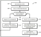
Fig. 4 is a diagram illustrating a method for rendering a display image of a video stream using a default tone mapping mode or a native tone mapping mode at a rendering device, according to some embodiments.
FIG. 5 is a diagram illustrating a method for receiving and displaying display images of a video stream at a display monitor based on a tone mapping mode for each display image, according to some embodiments.
Detailed Description
Conventional display systems employ a default color gamut range and a default luminance range when rendering display images of a video stream, thus forcing the display monitor receiving the video stream to perform post-processing on each received display image to re-map the received display image to the actual color gamut and luminance range (hereinafter referred to as the "native" color gamut and luminance range) implemented by the display monitor. The processing power of the display monitor is relatively limited compared to rendering devices that provide video streams, particularly when the Graphics Processing Unit (GPU) of the rendering device has a dedicated pipeline, so this second tone mapping process performed by the display monitor typically introduces considerable latency in the rendering to display pipeline. Furthermore, this remapping process may often result in the resulting display image being altered in a manner that is inconsistent with the content creator's original intent on the video stream. Furthermore, since GPUs typically have higher processing power than display monitors, images produced natively by GPUs are typically of better quality than post-processed images produced by display monitors.
Rather, the systems and techniques described herein employ a Graphics Processing Unit (GPU) of a rendering device to render a display image such that the display image is tone mapped to the native color gamut and luminance range of the display monitor before being transmitted to the display monitor and taking into account the particular backlight characteristics of the display monitor. This allows the display monitor to bypass the post-tone remapping process, thus providing a display image for display earlier after receipt at the display monitor. Furthermore, by originally rendering the display image according to the native color gamut and luminance range of the display monitor and the backlight characteristics, and thus eliminating the need for a second tone mapping process, less tone mapping errors are introduced in the final displayed display image, so the displayed image can more accurately represent the intent of the content creator.
Fig. 1 illustrates a comparison of a conventional default tone mapping method and a native tone mapping method, according to some embodiments. The conventional method is represented by a conventional mode display pipeline 100. In the conventional mode display pipeline 100, the display monitor identifies itself to the rendering device as conforming to a display specification, such as the high dynamic range 10(hdr.10) specification, the dolby vision specification, or the like, and the rendering device configures the conventional mode display pipeline 100 according to the identified display specification of the display monitor and initiates generation and transmission of the video stream using the conventional mode display pipeline 100. As will be appreciated, a video stream is composed of data representing a stream of display images and associated metadata. To generate the display image, a software application serving as a source of the video stream determines visual content to be rendered in the display image in stage 101, and a graphics driver, display driver, or other software interface configures a GPU of the rendering device to render the display image accordingly in stage 102.
The display specification identified by a display monitor typically employs a default color gamut and one or more luminance ranges. To illustrate, the hdr.10 specification implements the CEA 861.3HDR static metadata specification or bt.2020 specification, which provides a Wide Color Gamut (WCG) and a global luminance range of 0 to 10,000 nits. Thus, during a portion of the rendering process of stage 102, in the normal-mode display pipeline, the GPU of the rendering device is configured to perform initial tone mapping of the generated display image such that pixel values of the display image are mapped to corresponding codewords that conform to the default color gamut and default luminance range of the display specification. Thus, if the display monitor is implementing the hdr.10 display specification, the codewords representing the rendered display image will be mapped to a default wide color gamut and a default luminance range between 0 and 10,000 nits. At stage 103, the display image tone-mapped to the default color gamut/luminance range is encoded using a wired or wireless interconnection and corresponding transmission protocol, such as the DisplayPort specification, High Definition Multimedia Interface (HDMI) specification, or the like, and transmitted to a display monitor.
After receiving the display image, the display monitor prepares the display image for display. However, while display monitors may support the identified display specification for which the rendered and encoded display image is applicable, display monitors typically cannot fully or correctly display the default color gamut and luminance range of the display specification. To illustrate again using hdr.10, while the specification specifies a default wide color gamut and a luminance range of 0 to 10,000 nits, a display monitor may only be able to support a color gamut greater than the sRGB color space but less than the color space defined by the ITU-R bt.2020 specification, and a luminance range of only 0 to 400 nits. Thus, to prepare a display image for display, at stage 104 of the conventional mode display pipeline 100, the display monitor post-processes the received display image using its relatively limited processing power to tone remap the display image to a color gamut (e.g., greater than sRGB, less than bt.2020) and an illumination range (e.g., 0-400 nits) natively supported by the display monitor, where this process typically takes tens of milliseconds (ms) or longer. After the display image has been remapped to conform to the native color gamut/light luminance range of the display monitor, the display monitor continues to provide the remapped display image for display at stage 105.
Turning now to the native tone mapping method represented by the native mode display pipeline 110, in addition to identifying the display specification to which the display monitor is to comply, at an initialization stage 111, the rendering device determines the native color gamut and light brightness range actually supported by the display monitor, as well as the backlight parameters of the display monitor, such as whether local dimming or global backlight control is supported, and the light brightness range at the corresponding backlight mode or level. As described in more detail herein, this information may be supplied by the display monitor as part of Display Identification Data (DID) or extended DID (edid) supplied by the display monitor during initialization. The rendering device may then initiate a video streaming process to supply the display image stream to the display monitor for display, along with the corresponding metadata.
As with the conventional mode display pipeline 100, at stage 112, the source application at the rendering device determines the image content to be presented in the rendered display image. However, unlike the conventional mode display pipeline 100 in which the display image is rendered by the GPU according to the default color gamut and default luminance range, at stage 113 of the native mode display pipeline 110, the rendering device configures its GPU to render the display image such that the resulting display image is tone-mapped to the native color gamut and native luminance range provided by the display monitor. That is, rather than tone mapping the display image to a default gamut and luminance range, the native mode display pipeline tone maps the display image to a particular gamut and luminance range that the display monitor can actually support, i.e., the native gamut and native luminance range of the display monitor. As such, after transferring the rendered display image to the display monitor (stage 114), in the native mode display pipeline 110, the display monitor may proceed directly to providing the native mapped display image for display at stage 115, rather than having to tone remap the display image to the color space and light brightness levels that the display monitor can support (stage 104 of the conventional mode display pipeline 100).
Furthermore, the backlight plays a role in displaying native color gamut and light brightness at the display monitor, and thus in some embodiments, the rendering device configures the GPU to render the display image further based on the backlight parameters supplied by the display monitor. To illustrate, the backlight parameters include, for example, an indication as to whether the display monitor supports local dimming control by the source (i.e., where the backlight of different regions or zones of the display panel of the display monitor may be controlled individually by the source device) or global backlight control (i.e., where the backlight of the entire display panel is controlled as a whole, which may be controlled by the source device (i.e., GPU driver or hardware). For the global backlight mode, in some embodiments, the backlight parameters provided by the display monitor include one or more ranges. To illustrate, the backlight parameter may indicate a luminance of light emitted by the display monitor on a full white screen at a minimum backlight and a maximum backlight, and a parameter indicating a luminance of light emitted by the display monitor for a full black screen at the minimum backlight and the maximum backlight. In some embodiments, the backlight parameters for the local dimming mode are indicated by similar light brightness ranges.
The range or value of light brightness provided as part of the backlight parameters of the display monitor allows the GPU or rendering application of the rendering device to learn the characteristics of the display light brightness related to the backlight settings, thus allowing the GPU or rendering application to render the display content of the display image so that it is correctly presented at the display monitor. To illustrate, a display monitor may not achieve a certain light brightness level unless the backlight is set to a very low level or a very high level. Controlling the native rendering process in view of such backlight characteristics allows the content creator to render dark images by dynamically adjusting the display backlight in accordance with the indicated display light brightness, or to render bright pixels by dynamically setting the backlight to a high level, given the corresponding backlight settings, by configuration of the rendering application or GPU. The backlight characteristics may be represented in any of a variety of ways by the backlight parameters. In some implementations, a relatively simple min/max backlight mapping may be provided in the form of a linear mapping as represented or a default relatively simple curvilinear representation. Alternatively, the backlight characteristics may be represented by a more detailed curve describing the display light brightness at each backlight level.
As described below, in some embodiments, the rendering device and display monitor may switch between a conventional default tone mapping mode, represented by the conventional mode display pipeline 100, and a native tone mapping mode, represented by the native mode display pipeline 110, on an image-by-image basis. Thus, in such an implementation, at stage 116 (which occurs concurrently with stage 114), the rendering device signals to the display monitor whether the transmitted display image is default tone mapped or native tone mapped. To illustrate, both the HDMI and DisplayPort specifications provide for the transmission of metadata for each "frame" (i.e., display image) in the form of an InfoFrame associated with the frame, and thus indicators of tone mapping mode and frame-by-frame synchronized backlight control mode for the corresponding display image are included in the corresponding InfoFrame.
Comparing the conventional mode display pipeline 100 with the native mode display pipeline 100, it will be appreciated that the native mode display pipeline 110 implements only a single tone mapping process at stage 113 and avoids the second tone mapping process required by stage 104 of the conventional mode display pipeline 100. Since only the first tone mapping process is performed in the native mode display pipeline 110, the rendering-to-display latency of the native mode display pipeline 110 is reduced by tens of milliseconds or more compared to the conventional mode display pipeline. Furthermore, by requiring only an initial tone mapping process, the resulting display image, once rendered, may more closely conform to the intent of the content creator, and thus provide a more accurate viewing experience for the user.
Fig. 2 illustrates a display system 200 implementing the native mode display pipeline 110 of fig. 1, according to some embodiments. Display system 200 includes a rendering device 202 and a display monitor 204 connected by a wired or wireless interconnect 203. Rendering device 202 comprises any of a variety of devices for generating video content, including notebook computers, desktop computers, servers, game consoles, computing-capable smartphones, and the like. The display monitor 204 includes a digital display device, such as a digital television, a computer monitor, a portable device display, or the like, for displaying video content. Rendering device 202 includes at least one memory 206, at least one processor, such as GPU208 and Central Processing Unit (CPU)210, and display Interface (IF) 212. The display monitor 204 includes a display interface 214, a display controller 216, and a display matrix 218. The display interfaces 212, 214 include wired or wireless interconnect interfaces, such as HDMI interfaces, DisplayPort interfaces, embedded DisplayPort (edp) interfaces, and the like. The display controller 216 is implemented as one or more processors configured to execute software instructions stored in a memory (not shown), one or more programmable logic components, one or more hard-coded logic components, or a combination thereof. The display matrix 218 includes a two-dimensional array of pixels for displaying a series of display images, and includes, for example, a matrix of Light Emitting Diodes (LEDs), a matrix of organic LEDs (oleds), a matrix of Liquid Crystal Displays (LCDs), or the like.
As a general operational overview, the memory 206 stores one or more sets of executable software instructions configured to manipulate the CPU 210 and the GPU208 to render a video stream comprising a series of display images and corresponding metadata, and to transmit this video stream to the display monitor 204 via the display interfaces 212, 214 and the interconnect 203. At the display monitor, the display controller 216 receives each display image and corresponding metadata in turn, and processes the display images for sequential display at the display matrix 218. In at least one embodiment, the rendering device 202 and the display monitor 204 may be configured to implement the native mode display pipeline 110 of fig. 1 such that the EDID module 220 of the display controller 216 provides the rendering device 202 with an EDID or other configuration information packet specifying the native color gamut and one or more light brightness ranges supported by the display monitor 204, as well as backlight parameters indicating backlight mode capabilities (e.g., local dimming control by the source or global backlight control by the source), and parameters representative of the light brightness ranges at various backlight conditions or levels. Rendering device 202 controls GPU208 to render one or more of the display images of the video stream with a tone mapping consistent with the indicated native color gamut and native light luminance range and the indicated backlight characteristics, i.e., with native tone mapping. This process will be described in more detail below.
Fig. 3 illustrates software stacks implemented at a rendering device 202 and a display monitor 204 to implement native mode display pipeline 110, according to some embodiments. The software stack 302 is implemented in the rendering device 202 and includes one or more video content applications 304, one or more Operating System (OS) interfaces 306, a Software Developer Kit (SDK)/OS interface 308, a graphics driver 310, and a display driver 312. The video content application 304 comprises a software application that is the source of the video content to be rendered, such as a source of a gaming application, a Virtual Reality (VR) or Augmented Reality (AR) application, a video playback application, and so forth. Drawing instructions for the display image of the video content are provided to graphics driver 310 via OS interface 306, and GPU shader work control function 314 then controls the shaders of GPU208 to render the corresponding display image. The SDK/OS interface 308 includes an obtain display parameters function 316 that analyzes EDID, DID, or other configuration information packets provided by the display monitor 204 to determine various parameters of the display monitor 204, including its native color gamut and native light brightness range.
Display driver 312 includes tone mapping functionality 317 to configure GPU208 such that shader operations performed by GPU208 to render a display image are tone mapped to specified gamut and luma ranges, which may be default gamut and default luma ranges set by display specifications, or native gamut and native luma ranges, depending on the rendering mode. Furthermore, in some implementations, tone mapping function 317 also configures GPU208 such that shader operations reflect the backlight characteristics of a display monitor. The display driver 312 also includes an HDR InfoFrame function 318 for facilitating the generation and transmission of InfoFrames for each generated display image.
The software stack 320 represents a software stack implemented at the display monitor 204 and includes EDID functionality 322 (one implementation of the EDID module 220 of fig. 2) to generate EDID for the rendering device 202 during initialization. In some embodiments, the software stack 320 also includes a scalar configuration and electro-optical transfer function (EOTF) interface 324 for post-processing of display images that are not in accordance with display parameters supported by the display monitor 204; and a backlight control interface 326 for configuring the backlight of the display monitor 204 during display of the received display image in cooperation with the SDK/OS interface 308.
Fig. 4 and 5 together illustrate the operation of rendering device 202 and its software stack 302 (fig. 4), and display monitor 204 and its software stack 320 (fig. 5) for generating, transmitting, and displaying a video stream comprising a series of display images tone-mapped to a default gamut and luminance range of a display specification or tone-mapped to native gamut, luminance range, and backlight characteristics of a particular display monitor 204 coupled to rendering device 202. Turning to fig. 4, a video stream rendering method 400 is shown, according to some embodiments. The method 400 begins at block 402, where the rendering device 202 and the display monitor 204 detect each other via the interconnect 203. In response to the detection, the rendering apparatus 202 and the display monitor 204 start initialization of pairing. As part of this initialization process, at block 404, the display monitor 204 transmits data representing its display parameters to the rendering device 202. In one embodiment, this data is generated by the EDID module 220 of the display monitor 204 of fig. 2 (e.g., which is implemented as the EDID function 322 of fig. 3) and provided to the get display parameters function 316 of the rendering device 202 via the I2C bus or other side channel, as is known in the art. In other embodiments, the display configuration data is transmitted as, for example, displayid (did) or in a proprietary format.
Conventional EDIDs include various parameters of the display monitor that provide the EDID, including version, manufacturer, screen size, gamma settings, timing, refresh rate, etc. In at least one embodiment, the EDID module 220 extends conventional EDID by including chromaticity and luminance parameters of the display monitor 204 (where these parameters define native color gamut and native light luminance range of the display monitor 204) and including backlight parameters of the display monitor 204 (where the backlight parameters specify one or more of the backlight modes supported by the display monitor 204, light luminance values or ranges at different backlight conditions or levels, etc.). To illustrate, version 3 of the EIA/CEA-861 specification for EDID provides certain extension blocks, including the use of vendor-specific data blocks (VSDB) defined by the vendor. As such, in some embodiments, the EDID module 220 inserts a VSDB into the EDID to provide to the rendering device, where the VSDB provides accurate reports on native chromaticity and luminance values, such as by identifying one or more of: whether the display monitor 204 supports the native tone mapping mode, a chromaticity parameter of the display monitor 204, one or more luminance ranges of the display monitor, such as a minimum static panel luminance level and a maximum static panel luminance level at a maximum backlight, a minimum static panel luminance level and a maximum static panel luminance level at a minimum backlight, and so forth. For example, table 1 shows an example VSDB format for providing native light luminance capability in EDID (providing native color gamut capability in EDID) and table 2 shows another example VSDB format (with parameters related to native tone mapping mode highlighted in bold):
table 1: first VSDB example with native schema parameters to include in EDID


Supporting seamless local dimming control requires the display monitor to toggle enable/disable local dimming based on the values transmitted by the rendering device. If the display monitor supports seamless local dimming control, the following is suggested: the maximum luminance 1 field should be filled with the peak luminance value based on a 10% white block; the maximum luminance 2 field should be filled with an average luminance value based on a 100% all white pattern; the minimum luminance 1 field should be filled with a minimum luminance value based on a 100% black pattern; and the minimum brightness 2 field should be filled with a minimum brightness value based on a black image having white blocks at corners.
Table 2: a second VSDB example with native mode parameters to include in EDID (where parameters related to native tone mapping mode are emphasized in bold):

table 3 shows an example EDID incorporating VSDB according to the example of table 2 as [ data block 4] (where parameters related to the native tone mapping mode are emphasized in bold):
table 3: example EDID with native tone-mapped VSDB:


with the EDID indicating the native color gamut characteristics, the native light brightness range, and the backlight parameters of the display monitor 204 or otherwise signaled as sideband data during initialization, the SDK/OS interface 308 accesses the data of the EDID or other sideband data to determine whether the display monitor 204 supports native tone mapping support according to the corresponding bit field of the VSDB of the EDID at block 406. If the display monitor 204 does not enable native tone mapping, at block 408, the SDK/OS interface 308 signals the tone mapping function 317 of the display driver 312 to configure the GPU208 to render each display image of the video stream with default tone mapping according to the conventional mode display pipeline 100 described above.
Otherwise, if the bit field of the VSDB of EDID indicates that the display monitor 204 supports native tone mapping, then the SDK/OS interface 308 signals this capability to the display driver 312. In response, at block 410, the display driver 312 determines the native color gamut and light brightness range of the display monitor 204 by accessing the chromaticity values from the EDID representing the native color gamut of the display monitor (e.g., X-Y values for red, green, and blue chromaticities) and the light brightness values from the EDID representing the native light brightness range at various backlight levels or modes and backlight parameters (e.g., minimum to maximum light brightness when the backlight is at maximum brightness, minimum to maximum light brightness when the backlight is at minimum brightness, or maximum, minimum, and average light brightness when local dimming is enabled), and populates one or more tables or other data structures with the representative values for later use.
Upon completion of this initialization, at block 412, the video content application 304 manipulates the rendering device 202 to initiate generation of a video stream comprised of a series of display images and corresponding metadata for transmission to the display monitor 204 and display at the display monitor 204. For each display image to be generated, at block 414, the video content application 304 determines image content to be represented by the display image and provides a representation of this content to the graphics driver 310 via the OS interface 306.
At block 416, the graphics driver 310, or alternatively the display driver 312, determines whether the display image is to be rendered using native tone mapping or a conventional default tone mapping mode. To illustrate, in some cases, there may be multiple application windows open simultaneously, with some application windows being native tone mapped and others being default tone mapped. In this case, a conventional default tone mapping mode may be used to render the final display image incorporating all of the different application windows. Likewise, when the operating system composes different display content over the native color application, such as for displaying User Interface (UI) controls over the native display content, it is likely that the resulting combined display frame will be rendered according to the conventional default tone mapping mode.
If the display image is to be tone mapped to a default color space and luminance range of a display specification supported by display monitor 204, at block 418, tone mapping function 317 of display driver 312 configures GPU208 with chroma values for the default color gamut and luminance EOTF representing the default luminance range, and at block 420, GPU208 performs shader operations and other rendering operations based on these default parameters to render the display image with tone mapping consistent with the default color gamut and luminance range of the display specification. Tone-mapped content within a particular luminance range typically involves obtaining source display content, and compressing or cropping the content, or a combination of compression and cropping. For example, display content is typically rendered to an 8/10 bit ARGB surface or FP16 surface. With an 8/10 bit ARGB surface, the display content is typically already encoded in sRGB gamma, so the display content is already in a format that can be transmitted directly to the display monitor. As such, the display driver need only signal to the monitor that the content is sRGB encoded.
In the case of the FP16 surface, the display content is typically in linear space, with each value having the meaning of a particular lightness. Specifically, an FP16 value of 1 translates to X nit, an FP16 value of 2 translates to Y nit, an FP16 value of 0.5 translates to Z nit, and so on. This means that it needs to be tone mapped and encoded in some default industry format that the display monitor can understand. One method of such mapping and encoding is by clipping any display data that is outside the target luminance range. For example, assume that the GPU is configured to output at 8-bit depth per color, encoded at sRGB, and at SDR luminance range (which extends to at most X nits in this example assumption). Thus, an 8-bit value of 255 is expressed as the maximum SDR lightness of X nit. In one approach, FP16 values may be encoded in the sRGB gamma curve and any FP16 values above the value of 1 are clipped. In fact, any display content above the FP16 value of 1 will look the same because they are clipped to X nits (an 8-bit output value of 255). An alternative approach is to retain some detail in the display content above the FP16 value of 1. The content may be scaled in such a way that all values are scaled down, so that the maximum content value is now 1, and the resulting scaled content may be sRGB encoded.
Tone mapping for a particular gamut typically operates under a representation of the gamut defined by three X/Y coordinates representing the maximum red, green and blue color points that can be represented in the identified color space. If the display content is represented by a gamut that is larger than the gamut supported by the display monitor 204, gamut remapping is used to represent the display content in the smaller gamut. As with luma tone mapping, gamut remapping typically involves scaling, clipping, or a combination thereof. To illustrate, one common approach is to implement the gamut remapping function by multiplying the pixels by a 3 x 3 gamut remapping matrix, whereby the input pixel RGB x/y coordinates are multiplied by the 3 x 3 matrix to produce output pixel RGB x/y coordinate values. As will be appreciated, these approaches are somewhat unpredictable from the perspective of the content creator, and thus leaving the luminance and color clipping/mapping to the display monitor may provide unpredictable results that may not be consistent with the intent of the content creator.
Returning to block 416, if native tone mapping is active for the display image to be rendered, at block 422, the tone mapping functionality 317 of the display driver 312 accesses the native color gamut and luminance parameters stored at block 410 and configures the GPU208 with these parameters. At block 424, GPU208 renders the display image according to the configuration parameters such that the display image is tone-mapped to the native color gamut and native light luminance range represented by the parameters.
At block 426, display driver 312 encodes the data of the display image generated by the process of blocks 418 and 420 or blocks 422 and 424 according to an appropriate encoding/transmission protocol (such as DisplayPort or HDMI specification) and provides the resulting data for transmission to display monitor 204 via display IF 212 and interconnect 203. In the example of method 400, if native tone mapping is enabled by display monitor 204, a given display image of the transmitted video stream may be native tone mapped or default tone mapped, depending on one or more factors. Thus, to identify the tone mapping mode used to render the display image so that display monitor 204 can process the received display image accordingly, at block 428, display driver 312 provides metadata associated with the encoded display image to identify the tone mapping mode employed for the display image. The CEA-861 specification employed by at least some of the HDMI and DisplayPort specifications provides for the use of a sideband InfoFrame packet to supply metadata for an encoded display frame or display image on a frame-by-frame basis. Thus, in at least one embodiment, the HDR InfoFrame function 318 of the display driver 312 identifies the tone mapping mode employed to render the display image and generates an InfoFrame packet for transmission with the encoded display image, where the InfoFrame packet includes an identifier of the tone mapping mode. For example, Table 4 below shows an example format for the InfoFrame packet, where bit field PB 6-bit 3 identifies whether native tone mapping mode is used for the display image:
table 4: example InfoFrame Package with tone mapping mode identifier

When transmission of a display image rendered during a current iteration of the method 400 is initiated, the method 400 may return to block 414 for a next iteration for a next display image included in the output video stream.
Turning now to fig. 5, an example video stream display method 500 of the display monitor 204 is shown, according to some embodiments. The iterations of method 500 are performed for each encoded display image received in the video stream output from rendering device 202. Accordingly, at block 502, the display interface 214 receives data representing a display image from the rendering device 202 via the interconnect 203 and the display interface 214. Meanwhile, at block 504, the display interface 214 receives the InfoFrame package or other metadata for each image associated with the particular displayed image.
At block 506, the display controller 216 uses the tone map field of the InfoFrame packet to determine whether the display image was rendered with native tone mapping or with conventional default tone mapping. To illustrate, if the InfoFrame packet format of Table 4 above is used, a value of "0" at PB 6-bit 3 indicates that conventional default tone mapping is used, and a value of "1" indicates that native tone mapping is used. If the InfoFrame packet or other image metadata indicates that native tone mapping is used for the individual display image associated with the InfoFrame packet, the display controller 216 identifies the display image as having a range of color gamuts and luminance that is already compatible with the capabilities of the display matrix 218. Thus, at block 508, the display controller 216 is configured to override any user-specified on-screen display (OSD) settings that may interfere with the native color gamut and luminance range of the display image, and at block 510, the display controller 216 provides or otherwise prepares the display image for display at the display matrix 218 without requiring any further tone mapping to remap the display image from another color space and luminance range to the color space and luminance range actually supported by the display monitor 204.
Returning to block 506, if the display controller 216 instead determines that the display image is encoded according to the conventional default color gamut and luminance range, at block 512, the display controller 216 accesses any user-defined OSD settings related to color space or luminance settings, such as brightness, hue, saturation, and the like. Furthermore, some display monitor implementations even allow a user to override the EOTF implemented by the display monitor through OSD settings. To illustrate, such a display monitor may ignore indications from the display driver that video output from the rendering device is in, for example, the sRGB format and instead interpret the display data as being in gamma 2.6 EOTF. Thus, the ability of the display monitor 204 to signal such an EOTF override as a display parameter further supports accurate native tone mapping by the rendering device.
At block 514, the display controller 216 performs post-processing on the display image to tone map the display image to the native color space and native luminance range using an electro-optic transfer function, Perceptual Quantizer (PQ) curve, or gamma curve representing the mapping to the gamut and luminance range of the display monitor 204. This post-processing may also be based on the user-defined OSD settings determined at block 512, such as by multiplying the pixel data with a corresponding color adjustment matrix or modifying the applied EOTF to achieve various brightness, hue, and saturation settings. At block 516, the display controller 216 provides the generated tone-remapped display image for display at the display matrix 218.
In some embodiments, the above-described apparatus and techniques are implemented in a system (such as a rendering device or display monitor described above with reference to fig. 1-5) that includes one or more Integrated Circuit (IC) devices (also referred to as integrated circuit packages or microchips). Electronic Design Automation (EDA) and Computer Aided Design (CAD) software tools may be used to design and fabricate these IC devices. These design tools are typically represented as one or more software programs. The one or more software programs include code executable by a computer system to manipulate the computer system to operate circuitry representing one or more IC devices to perform at least a portion of a process to design or tune a manufacturing system to manufacture the circuitry. This code may include instructions, data, or a combination of instructions and data. Software instructions representing a design tool or a manufacturing tool are typically stored in a computer-readable storage medium accessible by a computing system. Also, code representing one or more stages of design or fabrication of an IC device may be stored in and accessed from the same computer-readable storage medium or different computer-readable storage media.
A computer-readable storage medium may include any non-transitory storage medium or combination of non-transitory storage media that is accessible by a computer system during use to provide instructions and/or data to the computer system. Such storage media may include, but are not limited to, optical media (e.g., Compact Discs (CDs), Digital Versatile Discs (DVDs), blu-ray discs), magnetic media (e.g., floppy disks, tape, or magnetic hard drives), volatile memory (e.g., Random Access Memory (RAM) or cache), non-volatile memory (e.g., Read Only Memory (ROM) or flash memory), or micro-electromechanical systems (MEMS) -based storage media. The computer-readable storage medium can be embedded in a computing system (e.g., system RAM or ROM), fixedly attached to a computing system (e.g., a magnetic hard drive), removably attached to a computing system (e.g., an optical disk or Universal Serial Bus (USB) based flash memory), or coupled to a computer system via a wired or wireless network (e.g., a Network Accessible Storage (NAS)).
In some embodiments, certain aspects of the techniques described above may be implemented by one or more processors of a processing system executing software. Software includes one or more sets of executable instructions stored or otherwise tangibly embodied on a non-transitory computer-readable storage medium. The software may include instructions and certain data that, when executed by one or more processors, manipulate the one or more processors to perform one or more aspects of the techniques described above. A non-transitory computer-readable storage medium may include, for example, a magnetic or optical disk storage device, a solid-state storage device (such as flash memory), a cache, a Random Access Memory (RAM), or one or more other non-volatile memory devices, among others. Executable instructions stored on a non-transitory computer-readable storage medium may be in source code, assembly language code, object code, or other instruction format that is interpreted or otherwise executable by one or more processors.
It should be noted that not all of the activities or elements described above in the general description are required, that a portion of a particular activity or device may not be required, and that one or more other activities may be performed, or that elements other than those described may be included. Further, the order in which activities are listed are not necessarily the order in which the activities are performed. In addition, the corresponding concepts have been described with reference to specific embodiments. However, one of ordinary skill in the art appreciates that various modifications and changes can be made without departing from the scope of the present disclosure as set forth in the claims below. Accordingly, the specification and figures are to be regarded in an illustrative rather than a restrictive sense, and all such modifications are intended to be included within the scope of the present disclosure.
Benefits, other advantages, and solutions to problems have been described above with regard to specific embodiments. However, the benefits, advantages, solutions to problems, and any feature(s) that may cause any benefit, advantage, or solution to occur or become more pronounced are not to be construed as a critical, required, or essential feature or feature of any or all the claims. Moreover, the particular embodiments disclosed above are illustrative only, as the disclosed subject matter may be modified and practiced in different but equivalent manners apparent to those skilled in the art having the benefit of the teachings herein. No limitations are intended to the details of construction or design herein shown, other than as described in the claims below. It is therefore evident that the particular embodiments disclosed above may be altered or modified and all such variations are considered within the scope of the disclosed subject matter. Accordingly, the protection sought herein is as set forth in the claims below.
Claims (18)
1. A display method, comprising:
obtaining, at a rendering device (202), display parameters (111, 316) of a display monitor (204) coupled to the rendering device, the display parameters including data identifying a native color gamut, a native light brightness range, and one or more backlight characteristics of the display monitor;
rendering, at a graphics processing unit (208) of the rendering device, a first display image that is tone-mapped to the native color gamut and the native light luminance range and that is based on the one or more backlight characteristics;
providing the first display image for receipt by the display monitor as part of a video stream; and
rendering, at the graphics processing unit, a second display image that is tone-mapped to a default color gamut and a default luminance range associated with a display specification supported by the display monitor; and
providing the second display image for receipt by the display monitor as part of the video stream.
2. The display method of claim 1, further comprising:
receiving the first display image at the display monitor; and
providing the first display image for display at the display monitor without tone remapping the first display image.
3. The display method of claim 1, further comprising:
receiving the first display image at the display monitor;
providing the first display image for display at the display monitor without tone remapping the first display image;
receiving the second display image at the display monitor;
tone remapping the second display image from the default color gamut to the native color gamut and from the default luminance range to the native luminance range to generate a tone-remapped display image; and
providing the tone-remapped display image for display at the display monitor.
4. The display method of claim 3, further comprising:
providing, from the rendering device to the display monitor, first metadata associated with the first display image, the first metadata identifying the first display image as tone-mapped to the native color gamut and native light intensity range; and
providing, from the rendering device to the display monitor, second metadata associated with the second display image, the second metadata identifying the second display image as tone-mapped to the default color gamut and default luminance range.
5. The display method of claim 4, wherein:
providing the first display image for display at the display monitor without tone remapping is in response to receiving the first metadata at the display monitor; and
tone remapping the second display image is performed in response to receiving the second metadata at the display monitor.
6. The display method of claim 1, wherein the one or more backlight characteristics comprise at least one of:
a source controlled global backlight supported by the display monitor; and
source controlled local dimming supported by the display monitor.
7. The display method of claim 1, wherein the one or more backlight characteristics comprise at least one of:
maximum panel brightness at maximum backlight level;
minimum panel brightness at maximum backlight level;
maximum panel brightness at minimum backlight level;
minimum panel brightness at minimum backlight level;
enabling peak panel brightness with local dimming; and
the average panel brightness in the case of local dimming is enabled.
8. The display method of claim 1, wherein obtaining the display parameter comprises:
providing, from the display monitor to the rendering apparatus, extended display identification data comprising a chromaticity value representing the native color gamut and one or more values representing the native light brightness range.
9. A display system (200), comprising:
a rendering device (202) configured to be coupled to a display monitor (204), the rendering device comprising:
a graphics processing unit (208) configured to render display images of a video stream to be displayed at the display monitor; and
a central processing unit (210) configured to:
obtaining display parameters (111, 316) of the display monitor, the display parameters comprising data identifying a native color gamut, a native light brightness range, and at least one backlight characteristic of the display monitor;
configuring the graphics processing unit to render a first display image of the video stream, the first display image tone-mapped to the native color gamut and the native light luminance range and based on the at least one backlight characteristic; and
configuring the graphics processing unit to render a second display image of the video stream that is tone mapped to a default color gamut and a default luminance range associated with a display specification supported by the display monitor.
10. The display system of claim 9, further comprising:
the display monitor, wherein the display monitor is configured to:
receiving the first display image; and
providing the first display image for display at the display monitor without tone remapping the first display image.
11. The display system of claim 9, further comprising:
the display monitor, wherein the display monitor is configured to:
receiving the first display image;
providing the first display image for display without tone remapping the first display image;
receiving the second display image;
tone remapping the second display image from the default color gamut to the native color gamut and from the default luminance range to the native luminance range to generate a tone-remapped display image; and
providing the tone-remapped display image for display.
12. The display system of claim 11, wherein the rendering device is further configured to:
providing first metadata associated with the first display image to the display monitor, the first metadata identifying the first display image as tone-mapped to the native color gamut and native light intensity range; and
providing second metadata associated with the second display image to the display monitor, the second metadata identifying the second display image as tone-mapped to the default color gamut and default luminance range.
13. The display system of claim 12, wherein the display monitor is further configured to:
providing the first display image for display without tone remapping in response to receiving the first metadata; and
tone remapping the second display image in response to receiving the second metadata.
14. The display system of claim 9, wherein the central processing unit is configured to obtain the display parameters by accessing extended display identification data that provides the display monitor to the rendering device, the extended display identification data including a chromaticity value representative of the native color gamut and one or more values representative of the native light brightness range.
15. A display method, comprising:
receiving, at a display monitor (204), a display image of the video stream from a rendering device (202);
receiving, at the display monitor, metadata associated with the display image, the metadata indicating whether the display image is tone-mapped to a native color gamut, a native light luminance range of the display monitor and based on one or more backlight characteristics of the display monitor, or to a default color gamut and a default light luminance range of a display specification supported by the display monitor;
in response to identifying the display image as tone mapped to the native color gamut, native light luminance range, and based on the metadata of one or more backlight characteristics of the display monitor, providing the display image for display at the display monitor without tone remapping the display image; and
in response to identifying the display image as the metadata tone-mapped to the default color gamut and default luminance range:
tone remapping the display image from the default color gamut to the native color gamut and from the default luminance range to the native luminance range to generate a tone-remapped display image; and
providing the tone-remapped display image for display at the display monitor.
16. The display method of claim 15, further comprising:
during an initialization process, providing display parameters from the display monitor to the rendering device, the display parameters including representations of the native color gamut and the native light brightness range of the display monitor.
17. The display method of claim 15, wherein the one or more backlight characteristics comprise at least one of:
a source controlled global backlight supported by the display monitor; and
source controlled local dimming supported by the display monitor.
18. The display method of claim 15, wherein the one or more backlight characteristics comprise at least one of:
maximum panel brightness at maximum backlight level;
minimum panel brightness at maximum backlight level;
maximum panel brightness at minimum backlight level;
minimum panel brightness at minimum backlight level;
enabling peak panel brightness with local dimming; and
the average panel brightness in the case of local dimming is enabled.
Applications Claiming Priority (3)
| Application Number | Priority Date | Filing Date | Title |
|---|---|---|---|
| US15/993,393 US10706812B2 (en) | 2018-05-30 | 2018-05-30 | Source-side tone mapping based on native color gamut and brightness of display |
| US15/993,393 | 2018-05-30 | ||
| PCT/IB2019/052613 WO2019229548A1 (en) | 2018-05-30 | 2019-03-29 | Source-side tone mapping based on native color gamut and brightness of display |
Publications (2)
| Publication Number | Publication Date |
|---|---|
| CN112334970A CN112334970A (en) | 2021-02-05 |
| CN112334970B true CN112334970B (en) | 2022-06-03 |
Family
ID=68692726
Family Applications (1)
| Application Number | Title | Priority Date | Filing Date |
|---|---|---|---|
| CN201980043311.7A Active CN112334970B (en) | 2018-05-30 | 2019-03-29 | Source side tone mapping based on native gamut and brightness of a display |
Country Status (6)
| Country | Link |
|---|---|
| US (1) | US10706812B2 (en) |
| EP (1) | EP3803843A4 (en) |
| JP (1) | JP7198292B2 (en) |
| KR (1) | KR102424259B1 (en) |
| CN (1) | CN112334970B (en) |
| WO (1) | WO2019229548A1 (en) |
Families Citing this family (4)
| Publication number | Priority date | Publication date | Assignee | Title |
|---|---|---|---|---|
| JP2021033045A (en) * | 2019-08-23 | 2021-03-01 | キヤノン株式会社 | Liquid crystal display device and control method therefor |
| KR20210142398A (en) * | 2020-05-18 | 2021-11-25 | 에스케이하이닉스 주식회사 | Local tone mapping circuit, image sensing device and operation method thereof |
| TWI779473B (en) * | 2021-02-02 | 2022-10-01 | 宏碁股份有限公司 | Electronic device, display method and machine readable medium |
| US11636828B1 (en) * | 2022-02-28 | 2023-04-25 | Freedom Scientific, Inc. | System and method for automatically adjusting a color filter of an interface |
Citations (2)
| Publication number | Priority date | Publication date | Assignee | Title |
|---|---|---|---|---|
| CN101641949A (en) * | 2007-04-03 | 2010-02-03 | 汤姆逊许可公司 | Methods and systems for displays with chromatic correction with differing chromatic ranges |
| US9501963B2 (en) * | 2008-07-18 | 2016-11-22 | Hewlett-Packard Development Company, L.P. | Color profiling of monitors |
Family Cites Families (13)
| Publication number | Priority date | Publication date | Assignee | Title |
|---|---|---|---|---|
| JP2001147667A (en) * | 1999-11-18 | 2001-05-29 | Hitachi Ltd | Liquid crystal monitor device |
| US7525548B2 (en) * | 2005-11-04 | 2009-04-28 | Nvidia Corporation | Video processing with multiple graphical processing units |
| JP2014066928A (en) * | 2012-09-26 | 2014-04-17 | Sharp Corp | Video signal supply device, display device, television receiver, display system, video signal supply method, display method, program, and recording medium |
| US8990446B2 (en) | 2012-10-04 | 2015-03-24 | Sony Computer Entertainment America, LLC | Method and apparatus for decreasing presentation latency |
| US9538155B2 (en) * | 2013-12-04 | 2017-01-03 | Dolby Laboratories Licensing Corporation | Decoding and display of high dynamic range video |
| US9710215B2 (en) * | 2014-03-31 | 2017-07-18 | Dolby Laboratories Licensing Corporation | Maximizing native capability across multiple monitors |
| GB2525388B (en) * | 2014-04-17 | 2021-01-13 | Advanced Risc Mach Ltd | Method of and apparatus for processing data for a display |
| CN105393549A (en) * | 2014-06-27 | 2016-03-09 | 松下知识产权经营株式会社 | Data output device, data output method, and data generation method |
| US10123005B2 (en) | 2015-03-06 | 2018-11-06 | Apple Inc. | Displays with unit-specific display identification data |
| US10616617B2 (en) * | 2015-04-23 | 2020-04-07 | Lg Electronics Inc. | Method and apparatus for transmitting or receiving broadcast signal |
| WO2016183239A1 (en) * | 2015-05-12 | 2016-11-17 | Dolby Laboratories Licensing Corporation | Metadata filtering for display mapping for high dynamic range images |
| EP3119086A1 (en) * | 2015-07-17 | 2017-01-18 | Thomson Licensing | Methods and devices for encoding/decoding videos |
| US10140953B2 (en) * | 2015-10-22 | 2018-11-27 | Dolby Laboratories Licensing Corporation | Ambient-light-corrected display management for high dynamic range images |
-
2018
- 2018-05-30 US US15/993,393 patent/US10706812B2/en active Active
-
2019
- 2019-03-29 CN CN201980043311.7A patent/CN112334970B/en active Active
- 2019-03-29 WO PCT/IB2019/052613 patent/WO2019229548A1/en unknown
- 2019-03-29 EP EP19811188.2A patent/EP3803843A4/en active Pending
- 2019-03-29 JP JP2020566604A patent/JP7198292B2/en active Active
- 2019-03-29 KR KR1020207037196A patent/KR102424259B1/en active IP Right Grant
Patent Citations (2)
| Publication number | Priority date | Publication date | Assignee | Title |
|---|---|---|---|---|
| CN101641949A (en) * | 2007-04-03 | 2010-02-03 | 汤姆逊许可公司 | Methods and systems for displays with chromatic correction with differing chromatic ranges |
| US9501963B2 (en) * | 2008-07-18 | 2016-11-22 | Hewlett-Packard Development Company, L.P. | Color profiling of monitors |
Non-Patent Citations (2)
| Title |
|---|
| AMD Announces FreeSync 2:Easier & Lower Latency HDR Gaming;Ryan Smith;《www.anandtech.com》;20170103;全文 * |
| SMPTE ST 2094 and Dynamic Metadata;Lars Borg;《SMPTE》;20170202;全文 * |
Also Published As
| Publication number | Publication date |
|---|---|
| WO2019229548A1 (en) | 2019-12-05 |
| JP2021526330A (en) | 2021-09-30 |
| KR20210014663A (en) | 2021-02-09 |
| US10706812B2 (en) | 2020-07-07 |
| JP7198292B2 (en) | 2022-12-28 |
| US20190371262A1 (en) | 2019-12-05 |
| CN112334970A (en) | 2021-02-05 |
| KR102424259B1 (en) | 2022-07-25 |
| EP3803843A1 (en) | 2021-04-14 |
| EP3803843A4 (en) | 2022-03-02 |
Similar Documents
| Publication | Publication Date | Title |
|---|---|---|
| CN112334970B (en) | Source side tone mapping based on native gamut and brightness of a display | |
| US8390642B2 (en) | System and method for color space setting adjustment | |
| EP2518719B1 (en) | Image range expansion control methods and apparatus | |
| KR102599950B1 (en) | Electronic device and control method thereof | |
| US11776508B2 (en) | Pre-display adaptive codeword mapping for display monitor with non-ideal electro-optical transfer function | |
| JP2008112133A (en) | Electronic equipment | |
| US11276368B2 (en) | Techniques for applying color transforms in rendering visual content | |
| US20220130315A1 (en) | Selection of color calibration profile data from display memory | |
| US11410283B2 (en) | Electronic device and control method thereof | |
| CN107534763A (en) | Adaptive color levels interpolation method and equipment | |
| US11837126B2 (en) | Factory calibration measurement data | |
| US8310502B2 (en) | System and method for adjusting display input values | |
| US20230029431A1 (en) | Dynamic gamma curve use for display | |
| US20240105088A1 (en) | Factory calibration measurement data | |
| US20240112606A1 (en) | Image processing device, operating method thereof, and display system including image processing device | |
| US20220358869A1 (en) | Brightness conversion data blocks | |
| US20230093744A1 (en) | Method for reducing gamut mapping luminance loss | |
| WO2022245355A1 (en) | Display calibration and color preset generation | |
| WO2023182973A1 (en) | User selected display panel adjustment | |
| KR20230172469A (en) | Display of images of different dynamic ranges | |
| JP2017227666A (en) | Display unit |
Legal Events
| Date | Code | Title | Description |
|---|---|---|---|
| PB01 | Publication | ||
| PB01 | Publication | ||
| SE01 | Entry into force of request for substantive examination | ||
| SE01 | Entry into force of request for substantive examination | ||
| GR01 | Patent grant | ||
| GR01 | Patent grant |