CN112229168B - Pathologic sampling chopping block drying apparatus - Google Patents
Pathologic sampling chopping block drying apparatus Download PDFInfo
- Publication number
- CN112229168B CN112229168B CN202011083099.8A CN202011083099A CN112229168B CN 112229168 B CN112229168 B CN 112229168B CN 202011083099 A CN202011083099 A CN 202011083099A CN 112229168 B CN112229168 B CN 112229168B
- Authority
- CN
- China
- Prior art keywords
- cavity
- back plate
- air outlet
- air
- microprocessor
- Prior art date
- Legal status (The legal status is an assumption and is not a legal conclusion. Google has not performed a legal analysis and makes no representation as to the accuracy of the status listed.)
- Active
Links
Images


Classifications
-
- F—MECHANICAL ENGINEERING; LIGHTING; HEATING; WEAPONS; BLASTING
- F26—DRYING
- F26B—DRYING SOLID MATERIALS OR OBJECTS BY REMOVING LIQUID THEREFROM
- F26B9/00—Machines or apparatus for drying solid materials or objects at rest or with only local agitation; Domestic airing cupboards
- F26B9/10—Machines or apparatus for drying solid materials or objects at rest or with only local agitation; Domestic airing cupboards in the open air; in pans or tables in rooms; Drying stacks of loose material on floors which may be covered, e.g. by a roof
-
- F—MECHANICAL ENGINEERING; LIGHTING; HEATING; WEAPONS; BLASTING
- F26—DRYING
- F26B—DRYING SOLID MATERIALS OR OBJECTS BY REMOVING LIQUID THEREFROM
- F26B21/00—Arrangements or duct systems, e.g. in combination with pallet boxes, for supplying and controlling air or gases for drying solid materials or objects
- F26B21/001—Drying-air generating units, e.g. movable, independent of drying enclosure
-
- F—MECHANICAL ENGINEERING; LIGHTING; HEATING; WEAPONS; BLASTING
- F26—DRYING
- F26B—DRYING SOLID MATERIALS OR OBJECTS BY REMOVING LIQUID THEREFROM
- F26B21/00—Arrangements or duct systems, e.g. in combination with pallet boxes, for supplying and controlling air or gases for drying solid materials or objects
- F26B21/004—Nozzle assemblies; Air knives; Air distributors; Blow boxes
-
- F—MECHANICAL ENGINEERING; LIGHTING; HEATING; WEAPONS; BLASTING
- F26—DRYING
- F26B—DRYING SOLID MATERIALS OR OBJECTS BY REMOVING LIQUID THEREFROM
- F26B25/00—Details of general application not covered by group F26B21/00 or F26B23/00
-
- F—MECHANICAL ENGINEERING; LIGHTING; HEATING; WEAPONS; BLASTING
- F26—DRYING
- F26B—DRYING SOLID MATERIALS OR OBJECTS BY REMOVING LIQUID THEREFROM
- F26B25/00—Details of general application not covered by group F26B21/00 or F26B23/00
- F26B25/06—Chambers, containers, or receptacles
- F26B25/14—Chambers, containers, receptacles of simple construction
- F26B25/18—Chambers, containers, receptacles of simple construction mainly open, e.g. dish, tray, pan, rack
- F26B25/185—Spacers; Elements for supporting the goods to be dried, i.e. positioned in-between the goods to build a ventilated stack
Landscapes
- Engineering & Computer Science (AREA)
- Mechanical Engineering (AREA)
- General Engineering & Computer Science (AREA)
- Sampling And Sample Adjustment (AREA)
Abstract
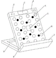
The invention provides a pathological material cutting board dryer which comprises a backboard and a bottom board which are arranged in an L shape, wherein a support is arranged on the back surface of the backboard, the bottom surface of the support is contacted with a horizontal table surface, the front surface of the backboard is arranged at an obtuse angle with the horizontal table surface by the support, the front surface of the bottom board is arranged at an acute angle with the horizontal table surface by the support, an air inlet is arranged on the back surface of the backboard, a cavity is arranged in the backboard, the air inlet is communicated with the cavity, an air outlet is arranged on the front surface of the backboard, the air outlet is communicated with the cavity, a fan is arranged in the cavity, the fan is connected with a microprocessor through a driving mechanism, the microprocessor is connected with a heating device, and the heating device is arranged in the cavity. According to the invention, the pathological material cutting board is placed on the table top formed by the back plate and the bottom plate, the fan draws air into the cavity from the air inlet, the air in the cavity is heated by the electric heating wire and then is discharged from the air outlet through the air outlet channel, and the pathological material cutting board covers the surface of the air outlet, so that the pathological material cutting board is favorably dried, the pathological material cutting board is ensured to be completely dry, and the influence on the accuracy of a material sample is avoided.
Description
Technical Field
The invention belongs to the technical field of mechanical structures, and particularly relates to a pathological material cutting board dryer.
Background
The chopping block of drawing materials is the common device that uses when pathology department doctor carries out the sample and draws materials, and at present, most chopping block of drawing materials mainly is wooden chopping block, uses the back for a long time, and wooden chopping block surface easily produces unevenness's sword mark or fracture, and easy embedding tissue or the wood sediment that falls cause the pollution.
Therefore, the material-drawing chopping block in the pathology department is required not to leave the residue of the previous specimen, otherwise, the pollution and the diagnosis error can be caused. Therefore, pathologists often wash the cutting board with tap water and disinfectants during the drawing of materials. In quick freezing material taking in the operation, the requirements on speed and cleanliness are more strict. And the chopping block cannot contain moisture, otherwise, ice crystals can be generated in the rapid freezing process, and the accuracy of diagnosis is influenced.
Generally, the freezing in the operation is spaced in time, the chopping block is washed clean and put on a rack for natural drying in the shade in the conventional operation, but the wooden chopping block has the characteristics of strong water absorption, difficult drying and the like, and the material drawing progress is influenced.
Disclosure of Invention
The invention aims to solve the problem of providing a dryer, in particular to a pathological material cutting board dryer which is simple in structure, convenient to operate, specially suitable for drying pathological material cutting boards, quick and convenient to use, low in production cost, small in occupied area and high in utilization rate.
In order to solve the technical problems, the invention adopts the technical scheme that: a chopping board dryer for pathologic sampling comprises a back board and a bottom board, wherein the back board and the bottom board are square boards, the back board and the bottom board are arranged in an L shape, a support is arranged on the back surface of the back board, the bottom surface of the support is in contact with a horizontal table surface, the support enables the front surface of the back board to be arranged at an obtuse angle with the horizontal table surface, the support enables the front surface of the bottom board to be arranged at an acute angle with the horizontal table surface, an air inlet is arranged on the back surface of the back board, a cavity is arranged in the back board, the air inlet is communicated with the cavity, an air outlet is arranged on the front surface of the back board, the air outlet is communicated with the cavity, a fan is arranged in the cavity, the fan is connected with a microprocessor through a driving mechanism, the microprocessor is connected with a heating device, the heating device is arranged in the cavity, and a water trough is arranged at the joint of the front surface of the back board and the upper surface of the bottom board, the water trough is obliquely arranged, and the vertical height of one end of the water trough is higher than that of the other end of the water trough.
Furthermore, a water storage box is arranged at the side face of the back plate close to the lower end of the vertical height of the water trough and communicated with the water trough.
Furthermore, the air inlets are long-strip-shaped, the air inlets are multiple, the multiple air inlets are uniformly distributed on the back face of the back plate, the air outlets are circular through holes, the air outlets are multiple, and the multiple air outlets are uniformly distributed on the front face of the back plate.
Furthermore, an air outlet channel is arranged inside the air outlet and is an L-shaped channel, and two ends of the air outlet channel are respectively connected with the air outlet and the cavity.
Furthermore, a plurality of bulges are arranged on the front surface of the back plate and are uniformly distributed on the front surface of the back plate.
Further, the backplate openly is equipped with infrared sensor, display screen and pilot lamp, infrared sensor arranges in the positive central point of backplate puts, infrared sensor connects microprocessor, be equipped with the countdown timer in the cavity, the countdown timer is connected respectively microprocessor the display screen with the pilot lamp, the display screen is arranged in the positive top central point of backplate puts, the pilot lamp is arranged in display screen one side.
Furthermore, the driving mechanism is a micro motor, the micro motor is respectively connected with the fan and the microprocessor, the microprocessor controls the working state of the micro motor, and the micro motor drives the fan to rotate so as to wind air into the cavity from the air inlet.
Further, the heating device is an electric heating wire which is distributed in the cavity in a disc shape.
Furthermore, a tweezers fixing device is arranged in the middle of one side face of the back plate, and a material taking knife fixing device is arranged in the middle of the other side face of the back plate.
The invention has the advantages and positive effects that:
1. the pathological material cutting board is simple in structure and convenient to operate, the pathological material cutting board is placed on a table top formed by the back plate and the bottom plate, the fan draws air into the cavity from the air inlet, the air in the cavity is heated by the electric heating wire and then is discharged from the air outlet through the air outlet channel, the pathological material cutting board covers the surface of the air outlet, the pathological material cutting board is favorably dried, the pathological material cutting board is ensured to be completely dry, and the accuracy of a material sample is prevented from being influenced.
2. According to the invention, the backboard and the bottom plate are obliquely arranged through the bracket, when the pathological material cutting board is arranged on the upper surface of the bottom plate, water on the pathological material cutting board flows down, and the pathological material cutting board is prevented from toppling due to unstable gravity center. The support sets up to the magnetism base, can hold the material mesa such as stainless steel, improves the stability of drying apparatus.
3. According to the pathological sampling chopping board, the water storage box is arranged at the lower end of the vertical height of the water trough, water on the pathological sampling chopping board flows into the water trough along the backboard, and water in the water trough flows into the water storage box, so that water is prevented from splashing around to pollute the environment.
4. The front surface of the back plate is provided with the plurality of bulges, so that the pathological material chopping block is prevented from being in large-area contact with the front surface of the back plate, a certain space is formed between the pathological material chopping block and the front surface of the back plate by the bulges, and the circulation of hot air from the air outlet is facilitated.
5. The front side of the backboard is provided with the infrared sensor, when the pathological material cutting board is placed in, the infrared sensor sends information to the microprocessor, the microprocessor drives the micro motor to work, the micro motor drives the fan to rotate, the electric heating wire works, the air outlet discharges hot air, meanwhile, the microprocessor drives the countdown timer to work, after the working time is up, the countdown timer sends information to the microprocessor, and the microprocessor drives the devices to stop working.
6. The button-type drying machine has the advantages that the heating temperature and the heating time are adjusted through the button, so that the optimal drying effect is obtained, meanwhile, the production cost and the energy consumption are saved to the greatest extent, the practicability is high, and the button-type drying machine is suitable for popularization and application.
7. According to the invention, the tweezers fixing device and the material taking knife fixing device are arranged at the central position of the side surface of the back plate, after specimen material taking is completed, the pathological material taking chopping block is placed in a space formed by the back plate and the bottom plate, meanwhile, the tweezers and the material taking knife required for material taking are placed at corresponding positions, and in the process of drying the pathological material taking chopping block, the tweezers and the material taking knife are dried by residual air at the same time, so that energy is fully utilized, and the multifunctional energy-saving and environment-friendly effects are achieved.
Drawings
Fig. 1 is a schematic view of the overall structure of the embodiment of the present invention.
Fig. 2 is a side view of the overall structure of an embodiment of the present invention.
FIG. 3 is a rear view of a backplane structure according to an embodiment of the present invention.
Fig. 4 is a sectional view of an air outlet channel structure according to an embodiment of the present invention.
Fig. 5 is a schematic diagram of a distribution structure of a fan and a micro motor according to an embodiment of the invention.
Fig. 6 is a schematic diagram of a distribution structure of the heating wire according to the embodiment of the present invention.
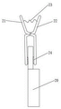
Fig. 7 is a schematic structural view of the forceps fixing device and the sampling blade fixing device according to the embodiment of the invention.
FIG. 8 is a schematic view of the combination of the clamping jaw mechanism and the material drawing knife according to the embodiment of the present invention.
In the figure:
1. indicator lamp 2, display screen 3, backplate
4. Bulge 5, infrared sensor 6, air outlet
7. Bottom plate 8, water trough 9 and bracket
10. Pathological material cutting board 11, air inlet 12 and cavity
13. Air outlet channel 14, fan 15 and micro motor
16. Electric heating wire 17, annular sleeve 18 and tweezers
19. Clamping jaw mechanism 20, material taking knife 21 and first clamping jaw
22. Second clamping jaw 23, return spring 24, antiskid.
Detailed Description
The technical solutions of the present invention will be described clearly and completely with reference to the accompanying drawings, and it should be understood that the described embodiments are some, but not all embodiments of the present invention. All other embodiments, which can be derived by a person skilled in the art from the embodiments given herein without making any creative effort, shall fall within the protection scope of the present invention.
In the description of the present invention, it should be noted that the terms "center", "upper", "lower", "left", "right", "vertical", "horizontal", "inner", "outer", etc., indicate orientations or positional relationships based on the orientations or positional relationships shown in the drawings, and are only for convenience of description and simplicity of description, but do not indicate or imply that the device or element being referred to must have a particular orientation, be constructed and operated in a particular orientation, and thus, should not be construed as limiting the present invention. Furthermore, the terms "first," "second," and "third" are used for descriptive purposes only and are not to be construed as indicating or implying relative importance.
In the description of the present invention, it should be noted that, unless otherwise explicitly specified or limited, the terms "mounted," "connected," and "connected" are to be construed broadly, e.g., as meaning either a fixed connection, a removable connection, or an integral connection; can be mechanically or electrically connected; they may be connected directly or indirectly through intervening media, or they may be interconnected between two elements. The specific meanings of the above terms in the present invention can be understood in specific cases to those skilled in the art.
Embodiments of the invention are further described below with reference to the accompanying drawings:
as shown in fig. 1, a pathological material cutting board dryer comprises a backboard 3 and a bottom board 7, wherein the backboard 3 and the bottom board 7 are square boards, and the backboard 3 and the bottom board 7 are arranged in an L shape. The back of the back plate 3 is provided with a support 9, the bottom surface of the support 9 is contacted with the horizontal table surface, the support 9 enables the front of the back plate 3 to form an obtuse angle with the horizontal table surface, and the support 9 enables the front of the bottom plate 7 to form an acute angle with the horizontal table surface. This embodiment is passed through support 9 and is placed backplate 3 and bottom plate 7 slope, as shown in fig. 2, when pathologic sampling chopping block 10 placed bottom plate 7 upper surface, be favorable to under the rivers on pathologic sampling chopping block 10, simultaneously, avoid pathologic sampling chopping block 10 to topple over because of the focus unstability. Support 9 can be multiple structure, as long as realize above-mentioned function can, specific, the support 9 that this embodiment provided is the magnetism base, can attract materials mesa such as stainless steel, improves the stability of drying apparatus.
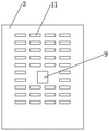
The back of the back plate 3 is provided with an air inlet 11, a cavity 12 is arranged inside the back plate 3, the air inlet 11 is communicated with the cavity 12, the air inlet 11 can be of various structures, specifically, as shown in fig. 3, the air inlet 11 of the embodiment is a long strip, the air inlets 11 are multiple, and the multiple air inlets 11 are uniformly distributed on the back of the back plate 3. The backplate 3 openly is equipped with air outlet 6, and air outlet 6 can be multiple structure, and is specific, as shown in fig. 1, the air outlet 6 and the cavity 12 intercommunication of this embodiment, and air outlet 6 is circular thru hole, and air outlet 6 is a plurality of, and a plurality of air outlets 6 evenly distributed are positive at backplate 3.
Preferably, as shown in fig. 4, an air outlet channel 13 is disposed inside the air outlet 6, the air outlet channel 13 is an "L" shaped channel, and two ends of the air outlet channel 13 are respectively connected to the air outlet 6 and the cavity 12. This embodiment sets up air-out passageway 13 to the L shape, avoids air outlet 6 and cavity 12 direct intercommunication, is equipped with heating device in the cavity 12, avoids the positive rivers of backplate 3 to get into cavity 12, and with the heating device contact, causes the short circuit, damages the drying apparatus and causes conflagration scheduling problem even.
As shown in fig. 5, a fan 14 is disposed in the cavity 12, the fan 14 is connected to a microprocessor through a driving mechanism, the microprocessor is connected to a heating device, and the heating device is disposed in the cavity 12. This embodiment is placed pathological material chopping block 10 on the mesa that backplate 3 and bottom plate 7 formed, and fan 14 is drawn into the cavity 12 with the air by air intake 11 in, and the air is behind the heating device heating in the cavity 12, is discharged by air outlet 6 through air-out passageway 13, and pathological material chopping block 10 covers on air outlet 6 surface, is favorable to drying pathological material chopping block 10, ensures that pathological material chopping block 10 is complete dry, avoids influencing the accuracy of the sample of drawing materials.
The driving mechanism is a device for driving the fan 14 to rotate and drawing the air outside the cavity 12 into the cavity 12, and the driving mechanism may have various structures as long as the above-described functions are achieved. Specifically, as shown in fig. 5, the driving mechanism provided in this embodiment is a micro motor 15, the micro motor 15 is connected to the fan 14 and the microprocessor respectively, the microprocessor controls the working state of the micro motor 15, and the micro motor 15 drives the fan 14 to rotate, so as to wind air into the cavity 12 from the air inlet 11.
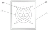
The heating device is a device for heating air entering the cavity 12 and making the air discharged from the air outlet 6 be warm air, and the heating device can be of various structures as long as the functions are realized. Specifically, the heating device provided in this embodiment is a heating wire 16, as shown in fig. 6, the heating wire 16 is distributed in a disc shape in the cavity 12.
Specifically, the micro motor 15 is directly connected to the fan 14, and after the micro motor 15 is powered on, the fan 14 is driven to rotate by the micro motor 15, and air sucked from the air inlet 11 passes through the heating wire 16 and is controlled by the switch button to become hot air or cold air sent from the air outlet 6. The heating wire 16 is normally only switched on to heat when the micro-motor 15 is energized, to avoid overheating and damaging the components. The simple method for adjusting the air temperature of the dryer is to rotate a button on the back plate 3; the temperature can be automatically controlled through the PTC element.
When the power is turned on, the heating wire 16 generates heat, and the air blown by the fan 14 passes through the heating wire 16 and becomes hot air. If only the fan 14 is rotated and the heating wires 16 are not heated, only wind is blown out without being heated. And multiple modes, which can be adjusted by buttons.
Preferably, as shown in fig. 1 and 2, a water trough 8 is provided at the junction of the front surface of the back plate 3 and the upper surface of the bottom plate 7, the water trough 8 is disposed in an inclined manner, and the vertical height of one end of the water trough 8 is higher than the vertical height of the other end of the water trough 8. The side of the back plate 3 is provided with a water storage box at the lower end close to the vertical height of the water trough 8, and the water storage box is communicated with the water trough 8.
This embodiment backplate 3 is equipped with trough 8 with 7 handing-over departments of bottom plate, and the slope of trough 8 is placed, and 8 vertical height low ends in trough are equipped with the water storage box, and water on the pathologic sampling chopping block 10 flows into trough 8 along backplate 3 in, and in the rivers income water storage box in the trough 8, avoids water to spatter everywhere, polluted environment.
Preferably, as shown in fig. 1 and 2, the front surface of the back plate 3 is provided with a plurality of protrusions 4, and the protrusions 4 are uniformly distributed on the front surface of the back plate 3. The protrusion 4 may have a plurality of structures, specifically, the protrusion 4 provided in this embodiment is a hemispherical surface, and the height of the protrusion 4 is 8 mm. This embodiment openly sets up a plurality of archs 4 at backplate 3, avoids pathologic sampling chopping block 10 and 3 openly large tracts of land contacts of backplate, and certain space is formed with pathologic sampling chopping block 10 and 3 openly between protruding 4, is favorable to the circulation of heat that air outlet 6 came out.
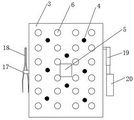
Preferably, as shown in fig. 1, the front of the back plate 3 is provided with an infrared sensor 5, a display screen 2 and an indicator lamp 1, the infrared sensor 5 is arranged in the center of the front of the back plate 3, the infrared sensor 5 is connected with a microprocessor, a countdown timer is arranged in the cavity 12, the countdown timer is connected with the microprocessor, the display screen 2 and the indicator lamp 1 respectively, the display screen 2 is arranged in the center of the top of the front of the back plate 3, and the indicator lamp 1 is arranged on one side of the display screen 2.
This embodiment backplate 3 openly is equipped with infrared sensor 5, when pathologic sampling chopping block 10 was put into, infrared sensor 5 sent information for microprocessor, microprocessor drive micro motor 15 work, micro motor 15 drives fan 14 and rotates, heating wire 16 work, air outlet 6 exhaust steam, and simultaneously, microprocessor drive countdown timer work, after operating time reachs, the countdown timer sends information for microprocessor, microprocessor drive above-mentioned each device stop work.
Heating temperature and heating time are adjusted through the button to obtain best stoving effect, furthest saves manufacturing cost and energy resource consumption simultaneously, and the practicality is strong, is fit for popularizing and applying. Specifically, the countdown time set by the countdown timer is 3 minutes, hot air is used for the first 2 minutes, and cold air is used for the last 1 minute, so that the pathological material cutting board 10 is dry and available.
The middle part of one side of the back plate 3 is provided with a tweezers fixing device, the tweezers fixing device is used for fixing the tweezers 18, and the tweezers 18 can be dried conveniently by using the residual air. The forceps fixing device can be in various structures as long as the above functions are achieved, specifically, as shown in fig. 7, the forceps fixing device provided by the embodiment is an annular sleeve 17, the forceps 18 are squeezed and inserted into the annular sleeve 17 and then released, and the annular sleeve 17 clamps the forceps 18 to prevent the forceps 18 from falling off.
The middle part of the other side surface of the backboard 3 is provided with a sampling knife fixing device. The material taking knife fixing device is a device for fixing the material taking knife 20 and conveniently drying the material taking knife 20 by utilizing residual air. The material drawing knife fixing device can be of various structures as long as the above functions are realized, and specifically, the material drawing knife 20 fixing device provided by the embodiment is the clamping jaw mechanism 19. As shown in fig. 8, the clamping jaw mechanism 19 comprises a first clamping jaw 21, a second clamping jaw 22, a first clamping jaw 21 and a second clamping jaw 22 which are hinged in an X shape, the top of the first clamping jaw 21 is connected with the top of the second clamping jaw 22 through a return spring 23, and the bottom of the first clamping jaw 21 and the bottom of the second clamping jaw 22 are respectively provided with an anti-skid device 24. When the return springs 23 at the tops of the first clamping jaw 21 and the second clamping jaw 22 are compressed, the distance between the bottoms of the first clamping jaw 21 and the second clamping jaw 22 is increased, and the material taking knife 20 is conveniently clamped. When the external force disappears, the return spring 23 between the first clamping jaw 21 and the second clamping jaw 22 is extended, the distance between the bottoms of the first clamping jaw 21 and the second clamping jaw 22 is reduced, and the clamping jaw mechanism 19 fixes the material taking knife 20. The anti-slip device 24 is a device for increasing the friction force between the clamping jaw mechanism 19 and the material-drawing knife 20 to clamp and fasten the material, and the anti-slip device 24 provided in this embodiment is a rubber pad.
According to the invention, the forceps fixing device and the material taking knife fixing device are arranged at the central position of the side surface of the back plate 3, after specimen material taking is completed, the pathological material taking chopping board 10 is placed in a space formed by the back plate 3 and the bottom plate 7, meanwhile, the forceps 18 and the material taking knife 20 required for material taking are placed at corresponding positions, and in the drying process of the pathological material taking chopping board 10, the forceps 18 and the material taking knife 20 are dried by residual air, so that energy is fully utilized, energy is saved, and the environment is protected.
Interaction between devices may be accomplished using a variety of signals and techniques. These signals and techniques include: orthogonal signals, CDMA, TDMA, FDMA, OFDMA, ultra wideband signals, chirp signals, laser signals, and many others. The signals to and from the microprocessor and devices may be modulated (using AM, FM, PSK, FSK, MSK, QAM, or any other possible modulation) or may be otherwise encoded or configured to contain timing, synchronization, control, data, multipath signal component identification, security codes, information to ensure proper operation, and redundancy. The signals to and from the microprocessor and devices may include Gold codes, PN codes, M-Sequence codes, Walsh-Hadamard codes, or any other codes. The microprocessor may be a conventional chip, a single chip, or a controller, and has a module with corresponding functions for driving the above devices to implement the above functions, which is not described herein again.
The connection modes of the microprocessor, the electric heating wire 16, the infrared sensor 5, the micro motor 15, the countdown timer, the display screen 2, the indicator light 1 and the buttons comprise wired connection and wireless connection. The wired connections may be connected by means of a serial bus, P1394, Thunderbolt, etc., and the wires in the wired connections are not shown in fig. 1 in order to avoid clutter. The wireless connection mode can be connected through modes such as Bluetooth, Bluetooth Low Energy, WIFI and Zigbee. The microprocessor and the heating wire 16, the infrared sensor 5, the micro motor 15, the countdown timer, the display screen 2, the indicator light 1, the buttons and the like may receive power through wired or wireless connection, and may also receive power from a disposable battery or a rechargeable battery.
The working principle of the invention is as follows:
the required drying time and the drying mode are adjusted through the button, specifically, the drying time set in the embodiment is three minutes, the air outlet 6 is hot air in the first two minutes, and the air outlet 6 is normal temperature air in the last one minute.
After washing pathological material chopping board 10 with water, place on the mesa of backplate 3 and bottom plate 7 formation, pathological material chopping board 10 and protruding 4 contacts, the water droplet on pathological material chopping board 10 flows into downwards in walking groove 8, walks the slope of water groove 8 and places, walks the 8 vertical height low sides in water groove and is equipped with the water storage box, in water on pathological material chopping board 10 flowed into along backplate 3 and walks in water groove 8, in the rivers of walking in the water groove 8 flow into the water storage box, avoid water to spatter everywhere, the polluted environment. The water storage box is movably connected with the back plate 3, so that accumulated water in the water storage box can be conveniently discharged.
After the infrared sensor 5 senses the pathological material cutting board 10, the infrared sensor 5 sends information to the microprocessor, the microprocessor drives the micro motor 15 to work, the micro motor 15 drives the fan 14 to rotate, the heating wire 16 works, the air outlet 6 discharges hot air, meanwhile, the microprocessor drives the countdown timer to work, after two minutes arrive, the countdown timer sends information to the microprocessor, the microprocessor drives the heating wire 16 to stop working, the air outlet 6 discharges normal temperature gas, after one minute arrives, the countdown timer sends information to the microprocessor, the microprocessor drives each device to stop working, and the air outlet 6 stops supplying air.
The invention has the advantages and positive effects that:
1. the pathological material cutting board is simple in structure and convenient to operate, the pathological material cutting board is placed on a table top formed by the back plate and the bottom plate, the fan draws air into the cavity from the air inlet, the air in the cavity is heated by the electric heating wire and then is discharged from the air outlet through the air outlet channel, the pathological material cutting board covers the surface of the air outlet, the pathological material cutting board is favorably dried, the pathological material cutting board is ensured to be completely dry, and the accuracy of a material sample is prevented from being influenced.
2. According to the invention, the backboard and the bottom plate are obliquely arranged through the bracket, when the pathological material cutting board is arranged on the upper surface of the bottom plate, water on the pathological material cutting board flows down, and the pathological material cutting board is prevented from toppling due to unstable gravity center. The support sets up to the magnetism base, can hold the material mesa such as stainless steel, improves the stability of drying apparatus.
3. According to the pathological sampling chopping board, the water storage box is arranged at the lower end of the vertical height of the water trough, water on the pathological sampling chopping board flows into the water trough along the backboard, and water in the water trough flows into the water storage box, so that water is prevented from splashing around to pollute the environment.
4. The front surface of the back plate is provided with the plurality of bulges, so that the pathological material chopping block is prevented from being in large-area contact with the front surface of the back plate, a certain space is formed between the pathological material chopping block and the front surface of the back plate by the bulges, and the circulation of hot air from the air outlet is facilitated.
5. The front side of the backboard is provided with the infrared sensor, when the pathological material cutting board is placed in, the infrared sensor sends information to the microprocessor, the microprocessor drives the micro motor to work, the micro motor drives the fan to rotate, the electric heating wire works, the air outlet discharges hot air, meanwhile, the microprocessor drives the countdown timer to work, after the working time is up, the countdown timer sends information to the microprocessor, and the microprocessor drives the devices to stop working.
6. The button-type drying machine has the advantages that the heating temperature and the heating time are adjusted through the button, so that the optimal drying effect is obtained, meanwhile, the production cost and the energy consumption are saved to the greatest extent, the practicability is high, and the button-type drying machine is suitable for popularization and application.
7. According to the invention, the tweezers fixing device and the material taking knife fixing device are arranged at the central position of the side surface of the back plate, after specimen material taking is completed, the pathological material taking chopping block is placed in a space formed by the back plate and the bottom plate, meanwhile, the tweezers and the material taking knife required for material taking are placed at corresponding positions, and in the process of drying the pathological material taking chopping block, the tweezers and the material taking knife are dried by residual air at the same time, so that energy is fully utilized, and the multifunctional energy-saving and environment-friendly effects are achieved.
While one embodiment of the present invention has been described in detail, the description is only a preferred embodiment of the present invention and should not be taken as limiting the scope of the invention. All equivalent changes and modifications made within the scope of the present invention shall fall within the scope of the present invention.
Claims (6)
1. The utility model provides a pathologic sampling chopping block drying apparatus which characterized in that: the water-cooling device comprises a back plate and a bottom plate, wherein the back plate and the bottom plate are square plates, the back plate and the bottom plate are arranged in an L shape, a support is arranged on the back surface of the back plate, the bottom surface of the support is in contact with a horizontal table surface, the front surface of the back plate and the horizontal table surface are arranged in an obtuse angle by the support, the front surface of the bottom plate and the horizontal table surface are arranged in an acute angle by the support, an air inlet is arranged on the back surface of the back plate, a cavity is arranged in the back plate, the air inlet is communicated with the cavity, an air outlet is communicated with the cavity, a fan is arranged in the cavity, the fan is connected with a driving mechanism, the microprocessor is connected with a heating device, the heating device is arranged in the cavity, a water-cooling, the air outlet is a plurality of air outlets which are uniformly distributed on the front surface of the back plate, an air outlet channel is arranged inside the air outlet and is an L-shaped channel, the two ends of the air outlet channel are respectively connected with the air outlet and the cavity, a plurality of bulges are arranged on the front surface of the back plate, and the bulges are uniformly distributed on the front surface of the back plate.
2. The pathologic material cutting chopping board dryer according to claim 1, wherein: the side surface of the back plate is close to the lower end of the vertical height of the water trough, and a water storage box is arranged at the lower end of the vertical height of the water trough and communicated with the water trough.
3. The pathologic material cutting chopping board dryer according to claim 1 or 2, wherein: the backplate openly is equipped with infrared sensor, display screen and pilot lamp, infrared sensor arranges in the positive central point of backplate puts, infrared sensor connects microprocessor, be equipped with the countdown timer in the cavity, the countdown timer is connected respectively microprocessor the display screen with the pilot lamp, the display screen is arranged in the positive top central point of backplate puts, the pilot lamp is arranged in display screen one side.
4. The pathologic material cutting chopping board dryer according to claim 1 or 2, wherein: the driving mechanism is a micro motor, the micro motor is respectively connected with the fan and the microprocessor, the microprocessor controls the working state of the micro motor, and the micro motor drives the fan to rotate to wind air into the cavity from the air inlet.
5. The pathologic material cutting chopping board dryer according to claim 1 or 2, wherein: the heating device is an electric heating wire which is distributed in the cavity in a disc shape.
6. The pathologic material cutting chopping board dryer according to claim 1 or 2, wherein: the middle part of one side surface of the back plate is provided with a tweezers fixing device, and the middle part of the other side surface of the back plate is provided with a material taking knife fixing device.
Priority Applications (1)
| Application Number | Priority Date | Filing Date | Title |
|---|---|---|---|
| CN202011083099.8A CN112229168B (en) | 2020-10-12 | 2020-10-12 | Pathologic sampling chopping block drying apparatus |
Applications Claiming Priority (1)
| Application Number | Priority Date | Filing Date | Title |
|---|---|---|---|
| CN202011083099.8A CN112229168B (en) | 2020-10-12 | 2020-10-12 | Pathologic sampling chopping block drying apparatus |
Publications (2)
| Publication Number | Publication Date |
|---|---|
| CN112229168A CN112229168A (en) | 2021-01-15 |
| CN112229168B true CN112229168B (en) | 2022-03-04 |
Family
ID=74112127
Family Applications (1)
| Application Number | Title | Priority Date | Filing Date |
|---|---|---|---|
| CN202011083099.8A Active CN112229168B (en) | 2020-10-12 | 2020-10-12 | Pathologic sampling chopping block drying apparatus |
Country Status (1)
| Country | Link |
|---|---|
| CN (1) | CN112229168B (en) |
Citations (18)
| Publication number | Priority date | Publication date | Assignee | Title |
|---|---|---|---|---|
| US3739484A (en) * | 1972-04-24 | 1973-06-19 | Prentice E Co | Pressure regulating system for a dryer apparatus |
| JPS6449531A (en) * | 1987-08-20 | 1989-02-27 | Heater Tec Service Kk | Apparatus for drying chopping board and dishcloth |
| US4975587A (en) * | 1988-07-04 | 1990-12-04 | Min Jenn Liaw | Container for storing and sterilizing a chopping board |
| CN201948877U (en) * | 2010-12-28 | 2011-08-31 | 叶润丞 | Water filtering chopping board bracket |
| CN202654001U (en) * | 2012-06-07 | 2013-01-09 | 大连职业技术学院 | Electric air drying type chopping board frame |
| CN203263174U (en) * | 2013-05-15 | 2013-11-06 | 林君怡 | Quickly-dried chopping board |
| CN203663124U (en) * | 2014-01-20 | 2014-06-25 | 吉林大学 | Household cutting board drying and sterilizing leaning support |
| CN203785384U (en) * | 2014-03-14 | 2014-08-20 | 上海应用技术学院 | Simple drying bracket |
| CN204889782U (en) * | 2015-06-19 | 2015-12-23 | 九阳股份有限公司 | Kitchen utensils and appliances chopping block frame |
| CN105770938A (en) * | 2016-03-09 | 2016-07-20 | 艾吉阳 | Integrated disinfection device for vegetable and fruit cutting boards and knives |
| CN106510513A (en) * | 2017-01-16 | 2017-03-22 | 江西锦雕卫浴有限公司 | Splayed cutting board drying support with stepped air ports |
| CN106524692A (en) * | 2017-01-16 | 2017-03-22 | 江西锦雕卫浴有限公司 | Drying, sterilizing and disinfecting cutting board cabinet |
| CN207012139U (en) * | 2017-02-09 | 2018-02-16 | 中山市科立泰电器有限公司 | A kind of chopping block machine |
| CN108402937A (en) * | 2018-05-15 | 2018-08-17 | 苏州宏泉高压电容器有限公司 | A kind of multi-functional epoxy resin chopping block |
| CN208319093U (en) * | 2017-08-28 | 2019-01-04 | 中国热带农业科学院橡胶研究所 | Convenient for the multi-functional chopping block of storage |
| CN110664287A (en) * | 2019-10-28 | 2020-01-10 | 浙江蚁族电器有限公司 | Multifunctional straight-lifting taking and placing type chopping board box and working method thereof |
| CN210220469U (en) * | 2019-07-10 | 2020-03-31 | 杭州若奇技术有限公司 | Drying apparatus and chopping block assembly |
| CN110960716A (en) * | 2019-12-19 | 2020-04-07 | 广东顺德潜龙工业设计有限公司 | Drying and sterilizing structure of chopping board sterilizer |
Family Cites Families (14)
| Publication number | Priority date | Publication date | Assignee | Title |
|---|---|---|---|---|
| GB512797A (en) * | 1938-03-15 | 1939-09-26 | A D T Ltd | Improvements in or relating to airing or drying cabinets |
| DE19816962C1 (en) * | 1998-04-17 | 1999-10-07 | Kendro Lab Prod Gmbh | Supporting frame for shelves within incubation cupboard or dry cupboard - obviates need for insulating cupboard walls to be penetrated by shelf support fittings |
| JP2002034805A (en) * | 2000-07-19 | 2002-02-05 | Ayumi Mihashi | Chopping board rack (that makes it possible to be tidy surroundings of chopping board and dry chopping board well) |
| CN2562713Y (en) * | 2002-08-08 | 2003-07-30 | 王海生 | Ultraviolet sterilizing chopping board |
| AU2003295867A1 (en) * | 2002-11-21 | 2004-06-18 | Transform Pharmaceuticals, Inc. | Freeze-drying microscope stage apparatus and process of using the same |
| JP2006280883A (en) * | 2005-04-01 | 2006-10-19 | Hisashi Nakamura | Self-support drying assisting tool for domestic article |
| CN201157289Y (en) * | 2007-12-30 | 2008-12-03 | 吴生锡 | Bracket of vegetable cutting-up board |
| CN102895686A (en) * | 2012-10-07 | 2013-01-30 | 张光裕 | Sterilization protective machine for chopping board |
| CN105078319A (en) * | 2014-05-14 | 2015-11-25 | 刘乐凝 | Damp-proof chopping board |
| CN104983332B (en) * | 2015-07-22 | 2018-03-06 | 曾晓银 | Intelligent antibacterial table trencher |
| CN207928517U (en) * | 2017-05-13 | 2018-10-02 | 唐善科 | A kind of direct insertion kitchen utensils storage disinfecting and sterilizing machine |
| CN108056686B (en) * | 2018-01-25 | 2021-09-14 | 浙江奕乌侬食品有限公司 | A clean frame of drying for placing chopping board |
| CN209018540U (en) * | 2018-08-03 | 2019-06-25 | 张先斌 | Novel cutter holder |
| CN109893006A (en) * | 2019-04-08 | 2019-06-18 | 刘红 | A kind of utility knife grillage |
-
2020
- 2020-10-12 CN CN202011083099.8A patent/CN112229168B/en active Active
Patent Citations (18)
| Publication number | Priority date | Publication date | Assignee | Title |
|---|---|---|---|---|
| US3739484A (en) * | 1972-04-24 | 1973-06-19 | Prentice E Co | Pressure regulating system for a dryer apparatus |
| JPS6449531A (en) * | 1987-08-20 | 1989-02-27 | Heater Tec Service Kk | Apparatus for drying chopping board and dishcloth |
| US4975587A (en) * | 1988-07-04 | 1990-12-04 | Min Jenn Liaw | Container for storing and sterilizing a chopping board |
| CN201948877U (en) * | 2010-12-28 | 2011-08-31 | 叶润丞 | Water filtering chopping board bracket |
| CN202654001U (en) * | 2012-06-07 | 2013-01-09 | 大连职业技术学院 | Electric air drying type chopping board frame |
| CN203263174U (en) * | 2013-05-15 | 2013-11-06 | 林君怡 | Quickly-dried chopping board |
| CN203663124U (en) * | 2014-01-20 | 2014-06-25 | 吉林大学 | Household cutting board drying and sterilizing leaning support |
| CN203785384U (en) * | 2014-03-14 | 2014-08-20 | 上海应用技术学院 | Simple drying bracket |
| CN204889782U (en) * | 2015-06-19 | 2015-12-23 | 九阳股份有限公司 | Kitchen utensils and appliances chopping block frame |
| CN105770938A (en) * | 2016-03-09 | 2016-07-20 | 艾吉阳 | Integrated disinfection device for vegetable and fruit cutting boards and knives |
| CN106510513A (en) * | 2017-01-16 | 2017-03-22 | 江西锦雕卫浴有限公司 | Splayed cutting board drying support with stepped air ports |
| CN106524692A (en) * | 2017-01-16 | 2017-03-22 | 江西锦雕卫浴有限公司 | Drying, sterilizing and disinfecting cutting board cabinet |
| CN207012139U (en) * | 2017-02-09 | 2018-02-16 | 中山市科立泰电器有限公司 | A kind of chopping block machine |
| CN208319093U (en) * | 2017-08-28 | 2019-01-04 | 中国热带农业科学院橡胶研究所 | Convenient for the multi-functional chopping block of storage |
| CN108402937A (en) * | 2018-05-15 | 2018-08-17 | 苏州宏泉高压电容器有限公司 | A kind of multi-functional epoxy resin chopping block |
| CN210220469U (en) * | 2019-07-10 | 2020-03-31 | 杭州若奇技术有限公司 | Drying apparatus and chopping block assembly |
| CN110664287A (en) * | 2019-10-28 | 2020-01-10 | 浙江蚁族电器有限公司 | Multifunctional straight-lifting taking and placing type chopping board box and working method thereof |
| CN110960716A (en) * | 2019-12-19 | 2020-04-07 | 广东顺德潜龙工业设计有限公司 | Drying and sterilizing structure of chopping board sterilizer |
Also Published As
| Publication number | Publication date |
|---|---|
| CN112229168A (en) | 2021-01-15 |
Similar Documents
| Publication | Publication Date | Title |
|---|---|---|
| CN201018665Y (en) | Maintenance instrument for hearing aid | |
| CN200986374Y (en) | Portable drying apparatus | |
| CN112229168B (en) | Pathologic sampling chopping block drying apparatus | |
| CN105107805A (en) | Intelligent detection washer | |
| CN212033592U (en) | Humidity automatic control device for large power distribution cabinet | |
| CN114867328A (en) | High-precision alternating-current variable-frequency electrical speed regulation cabinet | |
| CN206651750U (en) | Air fryer | |
| CN201954652U (en) | Energy-storage type air supply and humidification electric heater | |
| CN108787542A (en) | A kind of chemistry teaching instrument dedusting drying device and its application method | |
| CN213643651U (en) | Rotating wheel dehumidification device for medical test paper and storage system | |
| CN204950738U (en) | Face washing device | |
| CN205538390U (en) | Medical roast mascerating machine | |
| CN212222913U (en) | Domestic plant extraction of essential oil machine | |
| CN113017229A (en) | Hair comb | |
| CN112790501A (en) | Hair comb | |
| CN205358638U (en) | Electrothermal hair remover | |
| CN112971314A (en) | Hair comb and method for controlling heating temperature of hair comb | |
| CN208891799U (en) | A kind of hair dryer | |
| CN211130520U (en) | Mirror with mirror surface drying function | |
| CN217404461U (en) | Semiconductor high-low temperature testing device of silicon-based device and optical testing system of silicon-based device | |
| CN213476396U (en) | Ultraviolet disinfection dryer for underwear | |
| CN206390516U (en) | A kind of portable manicure sander | |
| CN205907523U (en) | Novel clothes drying machine | |
| CN111205930A (en) | Household plant essential oil extractor and operation method thereof | |
| CN213244381U (en) | Novel facial mask heater of structure |
Legal Events
| Date | Code | Title | Description |
|---|---|---|---|
| PB01 | Publication | ||
| PB01 | Publication | ||
| SE01 | Entry into force of request for substantive examination | ||
| SE01 | Entry into force of request for substantive examination | ||
| GR01 | Patent grant | ||
| GR01 | Patent grant |