CN112092811A - Predictive grade optimization in cruise control - Google Patents
Predictive grade optimization in cruise control Download PDFInfo
- Publication number
- CN112092811A CN112092811A CN202010560116.6A CN202010560116A CN112092811A CN 112092811 A CN112092811 A CN 112092811A CN 202010560116 A CN202010560116 A CN 202010560116A CN 112092811 A CN112092811 A CN 112092811A
- Authority
- CN
- China
- Prior art keywords
- speed
- vehicle
- block
- controller
- peak
- Prior art date
- Legal status (The legal status is an assumption and is not a legal conclusion. Google has not performed a legal analysis and makes no representation as to the accuracy of the status listed.)
- Granted
Links
- 238000005457 optimization Methods 0.000 title description 3
- 238000000034 method Methods 0.000 claims abstract description 142
- 238000012544 monitoring process Methods 0.000 claims abstract description 10
- 230000004044 response Effects 0.000 claims description 4
- 230000008569 process Effects 0.000 description 66
- 230000001133 acceleration Effects 0.000 description 29
- 238000004891 communication Methods 0.000 description 20
- 238000004378 air conditioning Methods 0.000 description 18
- 230000005540 biological transmission Effects 0.000 description 7
- 238000002485 combustion reaction Methods 0.000 description 7
- 239000000446 fuel Substances 0.000 description 7
- 238000013500 data storage Methods 0.000 description 6
- 238000012545 processing Methods 0.000 description 6
- 230000006870 function Effects 0.000 description 5
- 238000011069 regeneration method Methods 0.000 description 5
- 230000008929 regeneration Effects 0.000 description 4
- 238000004364 calculation method Methods 0.000 description 3
- 230000008859 change Effects 0.000 description 3
- 238000010586 diagram Methods 0.000 description 2
- 230000003287 optical effect Effects 0.000 description 2
- 230000006399 behavior Effects 0.000 description 1
- 230000001413 cellular effect Effects 0.000 description 1
- 230000008878 coupling Effects 0.000 description 1
- 238000010168 coupling process Methods 0.000 description 1
- 238000005859 coupling reaction Methods 0.000 description 1
- 230000007613 environmental effect Effects 0.000 description 1
- 230000004927 fusion Effects 0.000 description 1
- 230000005484 gravity Effects 0.000 description 1
- 238000007726 management method Methods 0.000 description 1
- 230000002085 persistent effect Effects 0.000 description 1
- 238000003825 pressing Methods 0.000 description 1
- 230000001172 regenerating effect Effects 0.000 description 1
- 239000004065 semiconductor Substances 0.000 description 1
- 230000011664 signaling Effects 0.000 description 1
- 239000000126 substance Substances 0.000 description 1
- 230000003319 supportive effect Effects 0.000 description 1
- 238000009423 ventilation Methods 0.000 description 1
Images


Classifications
-
- B—PERFORMING OPERATIONS; TRANSPORTING
- B60—VEHICLES IN GENERAL
- B60W—CONJOINT CONTROL OF VEHICLE SUB-UNITS OF DIFFERENT TYPE OR DIFFERENT FUNCTION; CONTROL SYSTEMS SPECIALLY ADAPTED FOR HYBRID VEHICLES; ROAD VEHICLE DRIVE CONTROL SYSTEMS FOR PURPOSES NOT RELATED TO THE CONTROL OF A PARTICULAR SUB-UNIT
- B60W30/00—Purposes of road vehicle drive control systems not related to the control of a particular sub-unit, e.g. of systems using conjoint control of vehicle sub-units
- B60W30/14—Adaptive cruise control
- B60W30/143—Speed control
- B60W30/146—Speed limiting
-
- B—PERFORMING OPERATIONS; TRANSPORTING
- B60—VEHICLES IN GENERAL
- B60W—CONJOINT CONTROL OF VEHICLE SUB-UNITS OF DIFFERENT TYPE OR DIFFERENT FUNCTION; CONTROL SYSTEMS SPECIALLY ADAPTED FOR HYBRID VEHICLES; ROAD VEHICLE DRIVE CONTROL SYSTEMS FOR PURPOSES NOT RELATED TO THE CONTROL OF A PARTICULAR SUB-UNIT
- B60W10/00—Conjoint control of vehicle sub-units of different type or different function
- B60W10/04—Conjoint control of vehicle sub-units of different type or different function including control of propulsion units
- B60W10/06—Conjoint control of vehicle sub-units of different type or different function including control of propulsion units including control of combustion engines
-
- B—PERFORMING OPERATIONS; TRANSPORTING
- B60—VEHICLES IN GENERAL
- B60W—CONJOINT CONTROL OF VEHICLE SUB-UNITS OF DIFFERENT TYPE OR DIFFERENT FUNCTION; CONTROL SYSTEMS SPECIALLY ADAPTED FOR HYBRID VEHICLES; ROAD VEHICLE DRIVE CONTROL SYSTEMS FOR PURPOSES NOT RELATED TO THE CONTROL OF A PARTICULAR SUB-UNIT
- B60W40/00—Estimation or calculation of non-directly measurable driving parameters for road vehicle drive control systems not related to the control of a particular sub unit, e.g. by using mathematical models
- B60W40/02—Estimation or calculation of non-directly measurable driving parameters for road vehicle drive control systems not related to the control of a particular sub unit, e.g. by using mathematical models related to ambient conditions
- B60W40/06—Road conditions
-
- B—PERFORMING OPERATIONS; TRANSPORTING
- B60—VEHICLES IN GENERAL
- B60W—CONJOINT CONTROL OF VEHICLE SUB-UNITS OF DIFFERENT TYPE OR DIFFERENT FUNCTION; CONTROL SYSTEMS SPECIALLY ADAPTED FOR HYBRID VEHICLES; ROAD VEHICLE DRIVE CONTROL SYSTEMS FOR PURPOSES NOT RELATED TO THE CONTROL OF A PARTICULAR SUB-UNIT
- B60W40/00—Estimation or calculation of non-directly measurable driving parameters for road vehicle drive control systems not related to the control of a particular sub unit, e.g. by using mathematical models
- B60W40/10—Estimation or calculation of non-directly measurable driving parameters for road vehicle drive control systems not related to the control of a particular sub unit, e.g. by using mathematical models related to vehicle motion
- B60W40/105—Speed
-
- B—PERFORMING OPERATIONS; TRANSPORTING
- B60—VEHICLES IN GENERAL
- B60W—CONJOINT CONTROL OF VEHICLE SUB-UNITS OF DIFFERENT TYPE OR DIFFERENT FUNCTION; CONTROL SYSTEMS SPECIALLY ADAPTED FOR HYBRID VEHICLES; ROAD VEHICLE DRIVE CONTROL SYSTEMS FOR PURPOSES NOT RELATED TO THE CONTROL OF A PARTICULAR SUB-UNIT
- B60W50/00—Details of control systems for road vehicle drive control not related to the control of a particular sub-unit, e.g. process diagnostic or vehicle driver interfaces
- B60W50/0097—Predicting future conditions
-
- B—PERFORMING OPERATIONS; TRANSPORTING
- B60—VEHICLES IN GENERAL
- B60W—CONJOINT CONTROL OF VEHICLE SUB-UNITS OF DIFFERENT TYPE OR DIFFERENT FUNCTION; CONTROL SYSTEMS SPECIALLY ADAPTED FOR HYBRID VEHICLES; ROAD VEHICLE DRIVE CONTROL SYSTEMS FOR PURPOSES NOT RELATED TO THE CONTROL OF A PARTICULAR SUB-UNIT
- B60W50/00—Details of control systems for road vehicle drive control not related to the control of a particular sub-unit, e.g. process diagnostic or vehicle driver interfaces
- B60W2050/0001—Details of the control system
- B60W2050/0019—Control system elements or transfer functions
- B60W2050/0026—Lookup tables or parameter maps
-
- B—PERFORMING OPERATIONS; TRANSPORTING
- B60—VEHICLES IN GENERAL
- B60W—CONJOINT CONTROL OF VEHICLE SUB-UNITS OF DIFFERENT TYPE OR DIFFERENT FUNCTION; CONTROL SYSTEMS SPECIALLY ADAPTED FOR HYBRID VEHICLES; ROAD VEHICLE DRIVE CONTROL SYSTEMS FOR PURPOSES NOT RELATED TO THE CONTROL OF A PARTICULAR SUB-UNIT
- B60W2520/00—Input parameters relating to overall vehicle dynamics
- B60W2520/10—Longitudinal speed
-
- B—PERFORMING OPERATIONS; TRANSPORTING
- B60—VEHICLES IN GENERAL
- B60W—CONJOINT CONTROL OF VEHICLE SUB-UNITS OF DIFFERENT TYPE OR DIFFERENT FUNCTION; CONTROL SYSTEMS SPECIALLY ADAPTED FOR HYBRID VEHICLES; ROAD VEHICLE DRIVE CONTROL SYSTEMS FOR PURPOSES NOT RELATED TO THE CONTROL OF A PARTICULAR SUB-UNIT
- B60W2530/00—Input parameters relating to vehicle conditions or values, not covered by groups B60W2510/00 or B60W2520/00
- B60W2530/10—Weight
-
- B—PERFORMING OPERATIONS; TRANSPORTING
- B60—VEHICLES IN GENERAL
- B60W—CONJOINT CONTROL OF VEHICLE SUB-UNITS OF DIFFERENT TYPE OR DIFFERENT FUNCTION; CONTROL SYSTEMS SPECIALLY ADAPTED FOR HYBRID VEHICLES; ROAD VEHICLE DRIVE CONTROL SYSTEMS FOR PURPOSES NOT RELATED TO THE CONTROL OF A PARTICULAR SUB-UNIT
- B60W2552/00—Input parameters relating to infrastructure
- B60W2552/15—Road slope, i.e. the inclination of a road segment in the longitudinal direction
-
- B—PERFORMING OPERATIONS; TRANSPORTING
- B60—VEHICLES IN GENERAL
- B60W—CONJOINT CONTROL OF VEHICLE SUB-UNITS OF DIFFERENT TYPE OR DIFFERENT FUNCTION; CONTROL SYSTEMS SPECIALLY ADAPTED FOR HYBRID VEHICLES; ROAD VEHICLE DRIVE CONTROL SYSTEMS FOR PURPOSES NOT RELATED TO THE CONTROL OF A PARTICULAR SUB-UNIT
- B60W2552/00—Input parameters relating to infrastructure
- B60W2552/20—Road profile, i.e. the change in elevation or curvature of a plurality of continuous road segments
-
- B—PERFORMING OPERATIONS; TRANSPORTING
- B60—VEHICLES IN GENERAL
- B60W—CONJOINT CONTROL OF VEHICLE SUB-UNITS OF DIFFERENT TYPE OR DIFFERENT FUNCTION; CONTROL SYSTEMS SPECIALLY ADAPTED FOR HYBRID VEHICLES; ROAD VEHICLE DRIVE CONTROL SYSTEMS FOR PURPOSES NOT RELATED TO THE CONTROL OF A PARTICULAR SUB-UNIT
- B60W2552/00—Input parameters relating to infrastructure
- B60W2552/25—Road altitude
-
- B—PERFORMING OPERATIONS; TRANSPORTING
- B60—VEHICLES IN GENERAL
- B60W—CONJOINT CONTROL OF VEHICLE SUB-UNITS OF DIFFERENT TYPE OR DIFFERENT FUNCTION; CONTROL SYSTEMS SPECIALLY ADAPTED FOR HYBRID VEHICLES; ROAD VEHICLE DRIVE CONTROL SYSTEMS FOR PURPOSES NOT RELATED TO THE CONTROL OF A PARTICULAR SUB-UNIT
- B60W2556/00—Input parameters relating to data
- B60W2556/45—External transmission of data to or from the vehicle
- B60W2556/50—External transmission of data to or from the vehicle of positioning data, e.g. GPS [Global Positioning System] data
-
- B—PERFORMING OPERATIONS; TRANSPORTING
- B60—VEHICLES IN GENERAL
- B60W—CONJOINT CONTROL OF VEHICLE SUB-UNITS OF DIFFERENT TYPE OR DIFFERENT FUNCTION; CONTROL SYSTEMS SPECIALLY ADAPTED FOR HYBRID VEHICLES; ROAD VEHICLE DRIVE CONTROL SYSTEMS FOR PURPOSES NOT RELATED TO THE CONTROL OF A PARTICULAR SUB-UNIT
- B60W2710/00—Output or target parameters relating to a particular sub-units
- B60W2710/06—Combustion engines, Gas turbines
- B60W2710/0666—Engine torque
-
- B—PERFORMING OPERATIONS; TRANSPORTING
- B60—VEHICLES IN GENERAL
- B60W—CONJOINT CONTROL OF VEHICLE SUB-UNITS OF DIFFERENT TYPE OR DIFFERENT FUNCTION; CONTROL SYSTEMS SPECIALLY ADAPTED FOR HYBRID VEHICLES; ROAD VEHICLE DRIVE CONTROL SYSTEMS FOR PURPOSES NOT RELATED TO THE CONTROL OF A PARTICULAR SUB-UNIT
- B60W2720/00—Output or target parameters relating to overall vehicle dynamics
- B60W2720/10—Longitudinal speed
- B60W2720/103—Speed profile
-
- B—PERFORMING OPERATIONS; TRANSPORTING
- B60—VEHICLES IN GENERAL
- B60W—CONJOINT CONTROL OF VEHICLE SUB-UNITS OF DIFFERENT TYPE OR DIFFERENT FUNCTION; CONTROL SYSTEMS SPECIALLY ADAPTED FOR HYBRID VEHICLES; ROAD VEHICLE DRIVE CONTROL SYSTEMS FOR PURPOSES NOT RELATED TO THE CONTROL OF A PARTICULAR SUB-UNIT
- B60W2720/00—Output or target parameters relating to overall vehicle dynamics
- B60W2720/30—Wheel torque
-
- B—PERFORMING OPERATIONS; TRANSPORTING
- B60—VEHICLES IN GENERAL
- B60W—CONJOINT CONTROL OF VEHICLE SUB-UNITS OF DIFFERENT TYPE OR DIFFERENT FUNCTION; CONTROL SYSTEMS SPECIALLY ADAPTED FOR HYBRID VEHICLES; ROAD VEHICLE DRIVE CONTROL SYSTEMS FOR PURPOSES NOT RELATED TO THE CONTROL OF A PARTICULAR SUB-UNIT
- B60W30/00—Purposes of road vehicle drive control systems not related to the control of a particular sub-unit, e.g. of systems using conjoint control of vehicle sub-units
- B60W30/18—Propelling the vehicle
- B60W30/18009—Propelling the vehicle related to particular drive situations
- B60W30/18109—Braking
- B60W30/18127—Regenerative braking
Landscapes
- Engineering & Computer Science (AREA)
- Transportation (AREA)
- Mechanical Engineering (AREA)
- Chemical & Material Sciences (AREA)
- Combustion & Propulsion (AREA)
- Automation & Control Theory (AREA)
- Physics & Mathematics (AREA)
- Mathematical Physics (AREA)
- Human Computer Interaction (AREA)
- Control Of Driving Devices And Active Controlling Of Vehicle (AREA)
Abstract
The cruise control method includes: receiving, by a controller of a vehicle, a set speed, a maximum allowable speed, and a minimum allowable speed, wherein each of the maximum allowable speed and the minimum allowable speed is a speed boundary of an allowable speed range; commanding, by the controller, the propulsion system to produce a commanded axle torque to maintain the set speed; monitoring a current speed of the vehicle; monitoring an altitude of terrain at a predetermined upcoming location of the vehicle based on upcoming altitude data from the map database; generating an altitude prediction table using an altitude of a terrain at a predetermined upcoming location of a vehicle; and determining a predicted speed of the vehicle at each of the predetermined upcoming locations of the vehicle based on the current speed of the vehicle and the elevation of the terrain at the predetermined upcoming location.
Description
Technical Field
The present disclosure relates to methods and systems for predictive grade optimization in cruise control.
Background
Cruise control is currently calibrated to tightly control the driver's set speed, and can be aggressive and inefficient in its attempt to maintain that speed in the event of a change in road grade. This results in lower fuel economy and unnatural behavior (e.g., aggressive fueling (tip-in) and downshifting when going up a hill, braking while going down a hill, etc.).
Disclosure of Invention
The present disclosure describes methods and systems for controlling cruise control of a vehicle.
Some cruise control algorithms achieve improved fuel economy in cruise control by allowing speed changes on grade, but the vehicle must react violently and inefficiently (on steep or extended grades) near the edges of the allowable speed window to stay within the driver's custom bandwidth. The presently disclosed predictive method uses upcoming altitude data to understand in advance when steady-state cruise control operation will result in a speed violation (drifting outside of the driver's limits). The vehicle will then prepare for the upcoming speed violation, and will adjust the torque command at the timely moment (in an efficient manner) using this understanding of the terrain ahead. The presently disclosed method receives driver inputs for a set speed, a minimum allowable speed, and a maximum allowable speed in cruise control. Further, the presently disclosed method calculates the axle torque required to maintain steady state operation at a set speed on a flat road assuming nominal road conditions (tire pressure, vehicle weight, no wind, etc.). The presently disclosed method commands and maintains steady state engine operation at the nominal road load axle torque defined above as long as the vehicle is not at risk of violating the driver's minimum/maximum speed constraints (and achieving higher fuel economy in the process). The presently disclosed method uses upcoming altitude data to understand when a critical (maximum or minimum) speed may be violated by an upcoming grade curve. Then, it uses this information in advance to prepare for the steep grade by: (a) increasing (ramping) the torque in time and preventing dropping below the minimum allowable speed for the driver; and (b) opportunistically using battery regeneration, powertrain downshifting and vehicle braking to prevent exceeding the maximum allowable speed for the driver.
In an aspect of the present disclosure, a presently disclosed cruise control method for controlling a vehicle includes: receiving, by a controller of a vehicle, a set speed, a maximum allowable speed, and a minimum allowable speed, wherein each of the maximum allowable speed and the minimum allowable speed is a speed boundary of an allowable speed range; commanding, by the controller, the propulsion system to produce a commanded axle torque to maintain the set speed; monitoring a current speed of the vehicle; monitoring an elevation of a terrain at a predetermined upcoming location of the vehicle based on upcoming elevation data from a map database or vehicle sensors/cameras; generating an altitude prediction table using an altitude of a terrain at a predetermined upcoming location of a vehicle, wherein the altitude prediction table includes a plurality of predicted altitude points; determining a predicted speed of the vehicle at each of the predetermined upcoming locations of the vehicle from a current speed of the vehicle and an altitude of terrain at the predetermined upcoming locations of the vehicle; generating a predicted speed schedule using the predicted speed of the vehicle at each of the predetermined upcoming locations of the vehicle; comparing each of the predicted speeds of the vehicle at each of the predetermined upcoming locations to an allowable speed range; determining whether at least one of the predicted speeds is outside of an allowable speed range; and in response to determining that at least one of the predicted speeds is outside of the allowable speed range, commanding, by the controller, a propulsion system of the vehicle to adjust the commanded axle torque so as to maintain the actual speed of the vehicle within the allowable speed range at each of the predetermined upcoming positions.
The cruise control method may further include: a first speed point in the predicted speed schedule is identified that is less than the minimum allowable speed. The cruise control method may further include: a first local minimum in the predicted speed table is sought. The cruise control method may further include: a distance from the current position of the vehicle to the position at the first local minimum is determined, wherein the distance from the current position of the vehicle to the position at the first local minimum is the peak distance.
The cruise control method may further include: the desired speed at the peak distance is set to the minimum allowable speed. The cruise control method may further include: a scaled predicted speed schedule is calculated based on the minimum allowable speed and the first local minimum. The cruise control method may further include: from the mass of the vehicle and the minimum allowable speed, the work input required to achieve the minimum allowable speed at the peak distance is calculated.
The cruise control method may further include: based on the required work input, the adjustment to the current road-carrying axle torque required to achieve the minimum allowable speed at the peak distance is calculated. The cruise control method may further include: the predicted speed schedule is recalculated based on the adjustment torque required to achieve the minimum allowable speed at the peak distance. The cruise control method may further include: commanding the propulsion system to produce an updated commanded axle torque, wherein the updated commanded axle torque is equal to the adjustment torque required to achieve the minimum allowable speed at the peak distance plus the commanded axle torque.
The cruise control method may further include: a first speed point in the predicted speed schedule is identified that is greater than the maximum allowable speed. The cruise control method may further include: a first local maximum in the predicted speed table is sought. The cruise control method may further include: a distance from the current position of the vehicle to the position at the first local maximum is determined, wherein the distance from the current position of the vehicle to the position at the first local maximum is the peak distance. The cruise control method may further include: the desired speed at the peak distance is set to the maximum allowable speed. The cruise control method may further include: a scaled predicted speed schedule is calculated based on the maximum allowable speed and the first local maximum.
The present disclosure also describes a vehicle system comprising a controller programmed to perform the method described above. In an aspect of the disclosure, a vehicle system includes: a propulsion system; and a controller in communication with the propulsion system. The controller is programmed to perform the method described above.
The present disclosure also provides the following technical solutions.
1. Cruise control method for controlling a vehicle, comprising:
receiving, by a controller of the vehicle, a set speed, a maximum allowed speed, and a minimum allowed speed, wherein each of the maximum allowed speed and the minimum allowed speed is a speed boundary of an allowed speed range;
commanding, by the controller, a propulsion system to produce a commanded axle torque to maintain the set speed;
monitoring a current speed of the vehicle;
monitoring an elevation of terrain at a predetermined upcoming location of the vehicle based on upcoming elevation data;
generating an altitude prediction table using the altitude of the terrain at the predetermined upcoming location of the vehicle, wherein the altitude prediction table includes a plurality of predicted altitude points;
determining a projected speed of the vehicle at each of the predetermined upcoming positions of the vehicle as a function of the current speed of the vehicle and the elevation of the terrain at the predetermined upcoming positions of the vehicle;
generating a projected speed schedule using the projected speeds of the vehicle at each of the predetermined upcoming locations of the vehicle;
comparing each of the expected speeds of the vehicle at each of the predetermined upcoming locations to the allowable speed range;
determining whether at least one of the projected speeds is outside of the allowable speed range; and
commanding, by the controller, the propulsion system of the vehicle to adjust the commanded axle torque in order to maintain the actual speed of the vehicle within the allowable speed range at each of the predetermined upcoming positions in response to determining that at least one of the projected speeds is outside the allowable speed range.
2. The cruise control method according to claim 1, further comprising: a first speed point in the predicted speed schedule that is less than the minimum allowable speed is identified.
3. The cruise control method according to claim 2, further comprising: a first local minimum in the predicted speed schedule is sought.
4. The cruise control method according to claim 3, further comprising: determining a distance from a current position of the vehicle to a position at the first local minimum, wherein the distance from the current position of the vehicle to the position at the first local minimum is a peak distance.
5. The cruise control method according to claim 4, further comprising: setting the desired speed at the peak distance to the minimum allowable speed.
6. The cruise control method according to claim 5, further comprising: a scaled predicted speed schedule is calculated based on the minimum allowable speed and the first local minimum.
7. The cruise control method according to claim 6, further comprising: calculating a work input required to achieve the minimum allowable speed at the peak distance based on the mass of the vehicle and the minimum allowable speed.
8. The cruise control method according to claim 7, further comprising: calculating, from the requested work input, an adjustment torque required to achieve the minimum allowable speed at the peak distance.
9. The cruise control method according to claim 8, further comprising: recalculating the predicted speed schedule based on the trim torque required to achieve the minimum allowable speed at the peak distance.
10. The cruise control method according to claim 9, further comprising: commanding the propulsion system to produce an updated commanded axle torque, wherein the updated commanded axle torque is equal to the adjustment torque required to achieve the minimum allowable speed at the peak distance plus the commanded axle torque.
11. The cruise control method according to claim 1, further comprising: a first speed point in the predicted speed schedule that is greater than the maximum allowable speed is identified.
12. The cruise control method according to claim 11, further comprising: a first local maximum in the predicted speed table is sought.
13. The cruise control method according to claim 12, further comprising: determining a distance from a current position of the vehicle to a position at the first local maximum, wherein the distance from the current position of the vehicle to the position at the first local maximum is a peak distance.
14. The cruise control method according to claim 13, further comprising: setting the desired speed at the peak distance to the maximum allowable speed.
15. The cruise control method according to claim 14, further comprising: a scaled predicted speed schedule is calculated based on the maximum allowable speed and the first local maximum.
16. A vehicle system, comprising:
a propulsion system;
a controller in communication with the propulsion system, wherein the controller is programmed to:
receiving a set speed, a maximum allowed speed, and a minimum allowed speed, wherein each of the maximum allowed speed and the minimum allowed speed is a speed boundary of an allowed speed range;
commanding a propulsion system to produce a commanded axle torque to maintain the set speed;
monitoring a current speed of the vehicle;
monitoring an elevation of terrain at a predetermined upcoming location of the vehicle based on upcoming elevation data;
generating an altitude prediction table using the altitude of the terrain at the predetermined upcoming location of the vehicle, wherein the altitude prediction table includes a plurality of predicted altitude points;
determining a projected speed of the vehicle at each of the predetermined upcoming positions of the vehicle as a function of the current speed of the vehicle and the elevation of the terrain at the predetermined upcoming positions of the vehicle;
generating a projected speed schedule using the projected speeds of the vehicle at each of the predetermined upcoming locations of the vehicle;
comparing each of the expected speeds of the vehicle at each of the predetermined upcoming locations to the allowable speed range;
determining whether at least one of the projected speeds is outside of the allowable speed range; and
in response to determining that at least one of the predicted speeds is outside of the allowable speed range, commanding the propulsion system of the vehicle to adjust the commanded axle torque so as to maintain the actual speed of the vehicle within the allowable speed range at each of the predetermined upcoming positions.
17. The vehicle system of claim 16, wherein the controller is programmed to identify a first speed point in the predicted speed schedule that is less than the minimum allowable speed.
18. The vehicle system of claim 17 wherein the controller is programmed to look for a predicted minimum speed.
19. The vehicle system of claim 18 wherein the controller is programmed to determine a distance from a current position of the vehicle to a position at the projected minimum speed, and the distance from the current position of the vehicle to the position at the projected minimum speed is a peak distance.
20. The vehicle system of claim 19 wherein the controller is programmed to set the desired speed at the peak distance to the minimum allowable speed.
The above features and advantages and other features and advantages of the present teachings are readily apparent from the following detailed description of the best modes and other embodiments for carrying out the present teachings when taken in connection with the accompanying drawings, as defined in the appended claims.
Drawings
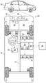
Fig. 1 is a schematic block diagram of a vehicle.
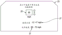
FIG. 2 is a schematic illustration of a portion of a user interface of the vehicle of FIG. 1.
FIG. 3 is a schematic illustration of an altitude prediction table representing the altitude of terrain at a predetermined upcoming location of a vehicle system.
FIG. 4 is a schematic illustration of a predicted speed schedule including predicted speeds of the vehicle system at each of predetermined upcoming positions of the vehicle system.
FIG. 5 is a schematic illustration of an updated predicted speed schedule.
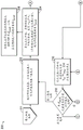
FIG. 6 is a flow chart of a method for controlling cruise control of the vehicle system of FIG. 1 to optimize fuel economy.
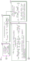
Fig. 7A is a first portion of an acceleration control process of the method of fig. 6.
Fig. 7B is a second portion of the acceleration control process of the method of fig. 6.
FIG. 7C is a third portion of an acceleration control process of the method of FIG. 6.
Fig. 8A is a first part of a deceleration control process of the method of fig. 6.
Fig. 8B is a second portion of a deceleration control process of the method of fig. 6.
Fig. 8C is a third portion of a deceleration control process of the method of fig. 6.
Fig. 8D is a fourth portion of a deceleration control process of the method of fig. 6.
Detailed Description
The following detailed description is merely exemplary in nature and is not intended to limit application and uses. Furthermore, there is no intention to be bound by any expressed or implied theory presented in the preceding technical field, background, brief summary or the following detailed description. As used herein, the term "module" refers to hardware, software, firmware, electronic control components, processing logic, and/or processor devices alone or in combination, including but not limited to: an Application Specific Integrated Circuit (ASIC), an electronic circuit, a processor (shared, dedicated, or group) and memory that execute one or more software or firmware programs, a combinational logic circuit, and/or other suitable components that provide the described functionality.
Embodiments of the disclosure may be described herein in terms of functional and/or logical block components and various processing steps. It should be appreciated that such block components may be realized by several hardware, software, and/or firmware components configured to perform the specified functions. For example, embodiments of the present disclosure may employ various integrated circuit components, e.g., memory elements, digital signal processing elements, logic elements, look-up tables, or the like, which may carry out a variety of functions under the control of one or more microprocessors or other control devices. Additionally, those skilled in the art will appreciate that embodiments of the present disclosure may be practiced in conjunction with several systems, and that the systems described herein are merely exemplary embodiments of the disclosure.
For the sake of brevity, techniques related to signal processing, data fusion, signaling, control, and other functional aspects of the systems (and the individual operating components of the systems) may not be described in detail herein. Furthermore, the connecting lines shown in the various figures contained herein are intended to represent example functional relationships and/or physical couplings between the various elements. It should be noted that alternative or additional functional relationships or physical connections may be present in an embodiment of the disclosure.
As depicted in fig. 1, the vehicle 10 generally includes a chassis 12, a body 14, front and rear wheels 17, and may be referred to as a primary vehicle. The vehicle 10 may be referred to as a motor vehicle. The body 14 is disposed on the chassis 12 and substantially encloses the components of the vehicle 10. The body 14 and the chassis 12 may together form a frame. The wheels 17 are each rotationally coupled to the chassis 12 near a respective corner of the body 14.
The vehicle 10 may be an autonomous vehicle, and the control system 89 is incorporated into the vehicle 10. The control system 89 may alternatively be referred to as a vehicle system. For example, the vehicle 10 is a vehicle that is automatically controlled to transport passengers from one location to another. In the illustrated embodiment, the vehicle 10 is depicted as a passenger car, but it should be understood that other vehicles may be used, including motorcycles, trucks, off-road vehicles (SUVs), Recreational Vehicles (RVs), marine vessels, aircraft, and the like. The vehicle 10 may be a so-called four-level or five-level automation system. The four-level system indicates "highly automated", meaning a driving pattern specific performance in terms of dynamic driving tasks by the autonomous driving system (even if the human driver does not respond appropriately to the intervention request). A five-level system indicates "fully automated," meaning full-time performance by an autonomous driving system in terms of dynamic driving tasks under different road and environmental conditions that can be managed by a human driver.
The sensor system 28 includes one or more sensing devices 40, the sensing devices 40 sensing observable conditions of the external environment and/or the internal environment of the vehicle 10. Sensing devices 40 may include, but are not limited to, radar, lidar, global positioning systems, optical cameras, thermographic cameras, ultrasonic sensors, clocks for measuring time, and/or other sensors. Actuator system 30 includes one or more actuator devices 42, which actuator devices 42 control one or more vehicle features, such as, but not limited to, propulsion system 20, transmission system 22, steering system 24, and braking system 26. In various embodiments, the vehicle features may also include interior and/or exterior vehicle features such as, but not limited to, doors, trunk, and cabin features, such as ventilation, music, lighting, and the like (not numbered). The sensing system 28 includes one or more Global Positioning System (GPS) transceivers 40g configured to detect and monitor route data (i.e., route information). The GPS transceiver 40g is configured to communicate with a GPS to locate the position of the vehicle 10 on the Earth. The GPS transceiver 40g is in electronic communication with the controller 34.
The data storage device 32 stores data for use in automatically controlling the vehicle 10. In various embodiments, the data storage 32 stores a defined map of the navigable environment. In various embodiments, the defined map may be predefined by the remote system and obtained from the remote system (described in further detail with respect to fig. 2). For example, the defined map may be assembled by a remote system and communicated to the vehicle 10 (wirelessly and/or in a wired manner) and stored in the data storage device 32. As can be appreciated, the data storage device 32 can be part of the controller 34, separate from the controller 34, or part of the controller 34 and part of a separate system.
The controller 34 includes at least one processor 44 and a computer non-transitory readable storage device or medium 46. The processor 44 may be a custom made or commercially available processor, a Central Processing Unit (CPU), a Graphics Processing Unit (GPU), an auxiliary processor among several processors associated with the controller 34, a semiconductor based microprocessor (in the form of a microchip or set of chips), a macroprocessor, a combination thereof, or a device for executing instructions generally. For example, the computer-readable storage device or medium 46 may include volatile and non-volatile storage in Read Only Memory (ROM), Random Access Memory (RAM), and non-volatile memory (KAM). The KAM is a persistent or non-volatile memory that may be used to store various operating variables when the processor 44 is powered down. The computer-readable storage device or medium 46 may be implemented using a number of storage devices, such as PROMs (programmable read Only memory), EPROMs (electrically PROM), EEPROMs (electrically erasable PROM), flash memory, or other electrical, magnetic, optical, or combination storage devices capable of storing data, some of which represent executable instructions, used by the controller 34 in controlling the vehicle 10. The data storage device 32 and/or computer readable storage device or medium 46 may include a map database 35. In the present disclosure, the term "map database" means a database storing geographic and topographic data, such as roads, streets, cities, parks, traffic signs, elevation information, two-or three-dimensional arrangements of objects having attributes of location and category. The map database 35 includes data regarding the elevation E of the terrain Trr (fig. 3) at predetermined upcoming positions of the vehicle 10. Data regarding the elevation E of the terrain Trr (fig. 3) at a predetermined upcoming position of the vehicle 10 is referred to herein as upcoming elevation data ED. In the present disclosure, the terrain Trr is the terrain Trr in which the vehicle 10 is traveling or is about to travel. The map database 35 may alternatively be referred to as a map module.
The instructions may comprise one or more separate programs, each of which comprises an ordered listing of executable instructions for implementing logical functions. When executed by the processor 44, the instructions receive and process signals from the sensor system 28, execute logic, calculations, methods, and/or algorithms for automatically controlling components of the vehicle 10, and generate control signals to the actuator system 30 based on the logic, calculations, methods, and/or algorithms to automatically control components of the vehicle 10. Although a single controller 34 is shown in fig. 1, embodiments of the vehicle 10 may include several controllers 34, the controllers 34 communicating over a suitable communication medium or combination of communication media and cooperating to process sensor signals, execute logic, calculations, methods and/or algorithms, and generate control signals to automatically control features of the vehicle 10.
In various embodiments, one or more instructions of controller 34 are implemented in control system 89. The vehicle 10 includes a user interface 23, which user interface 23 may be a touch screen in the dashboard. The user interface 23 is in electronic communication with the controller 34 and is configured to receive input by a user (e.g., a vehicle operator). Accordingly, the controller 34 is configured to receive input from a user via the user interface 23. The user interface 23 includes a display configured to display information to a user (e.g., a vehicle operator or passenger).
The communication system 36 is configured to wirelessly communicate information to and from other entities 48, such as, but not limited to, other vehicles ("V2V" communication), infrastructure ("V2I" communication), remote systems, and/or personal devices (described in more detail with respect to fig. 2). In an exemplary embodiment, the communication system 36 is a wireless communication system configured to communicate via a Wireless Local Area Network (WLAN) using the IEEE 802.11 standard or by using cellular data communication. However, additional or selectable communication methods, such as Dedicated Short Range Communication (DSRC) channels, are also contemplated within the scope of the present disclosure. DSRC channels refer to one-way or two-way short-to-mid-range wireless communication channels designed specifically for automotive use, as well as corresponding sets of protocols and standards. Accordingly, communication system 36 may include one or more antennas and/or transceivers to receive and/or transmit signals, such as Cooperative Sensing Messages (CSM).
Fig. 1 is a schematic block diagram of a control system 89, the control system 89 being configured to control a vehicle 10. The controller 34 of the control system 89 is in electronic communication with the braking system 26, the propulsion system 20, and the sensor system 28. The braking system 26 includes one or more brake actuators (e.g., brake calipers) coupled to one or more wheels 17. When actuated, the brake actuator applies brake pressure on one or more wheels 17 to slow the vehicle 10. The propulsion system 20 includes one or more propulsion actuators for controlling the propulsion of the vehicle 10. For example, as discussed above, the propulsion system 20 may include an internal combustion engine 33, and in this case, the propulsion actuator may be a throttle valve specifically configured to control airflow in the internal combustion engine. Sensor system 28 may include one or more accelerometers (or one or more gyroscopes) coupled to one or more wheels 17. The accelerometer is in electronic communication with the controller 34 and is configured to measure and monitor longitudinal and lateral acceleration of the vehicle 10. The sensor system 28 may include one or more speed sensors 40s, the speed sensors 40s configured to measure and monitor the speed (or velocity) of the vehicle 10. The speed sensor 40s is coupled to the controller 34 and is in electronic communication with the one or more wheels 17. Thus, the controller 34 is programmed to monitor the speed of the vehicle 10 based on input from the speed sensor 40 s.
Fig. 2 is a schematic view of a portion of the user interface 23. The vehicle 10 has cruise control and the driver's set speed 25 (shown in the user interface 23) may be adjusted by the driver using, for example, an up/down arrow on the steering wheel of the vehicle 10. In addition to the driver's set speed 25, the user interface 23 also displays a speed tolerance 27, which speed tolerance 27 comprises a maximum allowable speed and a minimum allowable speed. The driver may adjust the maximum allowable speed and/or the minimum allowable speed of the speed tolerance using the user interface 23. The user interface 23 displays an allowable speed range 37, the allowable speed range 37 being calculated from the set speed, the maximum allowable speed, and the minimum allowable speed. The maximum allowable speed and the minimum allowable speed are each a speed boundary of the allowable speed range 37.
Referring to fig. 3, the present disclosure describes a method 100 (fig. 6) that uses upcoming altitude data ED to understand in advance when steady-state cruise control operation will result in a speed violation (drifting outside of the driver's limits). The vehicle 10 may then prepare for the impending violation, and will adjust the torque command at the timely moment (in an efficient manner) using this understanding of the terrain ahead Trr. To do so, the controller 34 receives and monitors elevation data ED about the upcoming terrain Trr from the map database 35 and/or vehicle sensors/cameras (e.g., sensor system 28). As discussed above, data regarding the elevation E of the terrain Trr (fig. 3) at a predetermined upcoming location of the vehicle 10 is referred to herein as upcoming elevation data ED. Using this upcoming altitude data, the controller 34 then generates an altitude prediction table EDT, as described in detail below. The altitude prediction table EDT includes a plurality of predicted altitude points. The predicted elevation points are equidistant from each other. In other words, the predicted points are spaced from each other by a predetermined distance, and the first predicted point is spaced from the current position of the vehicle 10 by the same predetermined distance.
Referring to fig. 4, the controller 34 determines (i.e., calculates) the predicted speed of the vehicle 10 at each predicted altitude point. In other words, the controller is programmed to determine the expected speed of the vehicle 10 at each of the predetermined upcoming positions of the vehicle 10 based on the current speed of the vehicle 10 and the elevation E of the terrain Trr at the predetermined upcoming positions of the vehicle 10. The controller 34 then generates a predicted speed table PST using the predicted speed PS of the vehicle 10 at each of the predetermined upcoming positions of the vehicle 10. Next, the controller 34 determines whether there is a speed violation V. In other words, controller 34 determines whether one or more of the predicted speeds are outside of allowable speed range 37 (fig. 2), as discussed in detail below.
Referring to fig. 5, after identifying the speed violation V, the controller 34 calculates the necessary increase in initial torque to accommodate the altitude change, resulting in the speed allowed range 37 (fig. 2) being satisfied. An increase in the calculated axle torque results in a new predicted speed profile for the same altitude, now allowing the speed deviation margin to be met. In other words, the controller 34 generates an updated predicted speed table UPST based on the increased calculated axle torque, as discussed in detail below.
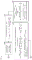
FIG. 6 is a flow chart of a cruise control method 100 for controlling the cruise control of the vehicle 10 of FIG. 1 to optimize fuel economy. The method 100 begins at block 102. At block 102, the controller 34 determines that cruise control has been engaged by the vehicle driver. The vehicle operator may engage in cruise control through the user interface 23. For example, the vehicle driver may press a button on the user interface 23 to engage in cruise control. At block 102, the vehicle operator may also set the set speed v via the user interface 23, for example, by pressing an up/down arrow on the steering wheel of the vehicle 10ssMaximum allowable speed vmaxAnd minimum allowable velocity vmin. Accordingly, at block 102, controller 34 receives the set speed v from user interface 23ssMaximum allowable speed vmaxAnd minimum allowable velocity vmin. As discussed above, the maximum allowable speed vmaxAnd minimum allowable velocity vminAre the speed boundaries of the allowed speed range 37. At block 102, the controller 34 also determines and (real-time) monitors the current vehicle speed based on the input of the speed sensor 40sv. The method 100 then proceeds to block 104. At block 102, the controller 34 determines and monitors the elevation E of the terrain Trr at a predetermined upcoming position of the vehicle 10 using the upcoming elevation data of the map database 35. After block 102, the method 100 proceeds to block 104.
At block 104, the controller 34 is at the set speed vssWill command axle torque taussThe road load torque is set. To do so, controller 34 commands propulsion system 20 to produce a commanded axle torque τssTo do so byThe set speed v is maintainedss. The method 100 then continues to block 106.
At block 106, the controller 34 generates an elevation prediction table EDT (fig. 3) using the elevation E of the terrain Trr at the predetermined upcoming position of the vehicle 10. As discussed above, the altitude prediction table EDT (fig. 3) includes a plurality of predicted altitude points that correspond to predetermined upcoming positions of the vehicle 10. The controller 34 uses the upcoming altitude data ED from the map database 35 to generate the altitude prediction table EDT. Thus, block 106 also entails obtaining altitude data ED from the map database 35 and then using the upcoming altitude data ED to generate the altitude prediction table EDT. The predicted altitude points of the altitude prediction table EDT are equidistant from each other. In other words, the predicted points are spaced from each other by a predetermined distance, and the first predicted point is spaced from the current position of the vehicle 10 by the same predetermined distance. The method 100 then proceeds to block 108.
At block 108, the controller 34 bases on the current speed v of the vehicle 100And the elevation E of the terrain Trr at the predetermined upcoming positions of the vehicle 10, determine the predicted speed of the vehicle at each of the predetermined upcoming positions of the vehicle. To this end, the controller 34 assumes that the vehicle 10 maintains a constant torque (i.e., the set speed v)ssRoad load torque below), and the predicted speed at each predicted point in the altitude table EDT (given the change in altitude in the altitude table EDT) is calculated using the following equation:
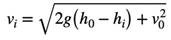
wherein the content of the first and second substances,
v 0 is the current speed of the vehicle 10;
h 0 is the current elevation of the terrain Trr at the current position of the vehicle 10;
h i is a point in the elevation prediction Table EDTiThe altitude of the location;
g is the acceleration of gravity; and
v i is a point in the elevation prediction Table EDTiThe predicted speed of (c).
Using the above equations, the controller 34 calculates the predicted speed at each predicted point and generates a predicted speed table PST (fig. 4) using the predicted speed of the vehicle 10 at each of the predetermined upcoming positions of the vehicle 10. After block 108, the method 100 proceeds to block 110.
At block 110, the controller 34 compares each of the predicted speeds at each of the predetermined upcoming positions to the allowable speed range 37 to determine whether any of the predicted speeds are outside the allowable speed range 37. In other words, at block 110, the controller 34 determines whether there is a violation of the maximum allowable speed v in the predicted speed table PST (FIG. 4)maxAnd/or minimum allowable speed vminAny predicted speed of. If there is no violation of the maximum allowable velocity vmaxAnd/or minimum allowable speed vminThe method 100 returns to block 104. If there is a violation of the maximum allowable velocity vmaxThe controller 34 initiates a deceleration control process 300 at block 112 (fig. 8A, 8B, 8C, and 8D). In the deceleration control process 300, the controller 34 commands the propulsion system 20 of the vehicle 10 to adjust the commanded axle torque to maintain the actual speed of the vehicle 10 within the allowable speed range 37 at each of the predetermined upcoming positions. After performing the deceleration control process, the method 100 proceeds to return to block 104. If there is a violation of the minimum allowable velocity vminThe controller 34 begins the acceleration control process 200 at block 114 (fig. 7A, 7B, and 7C). In the acceleration control process 200, the controller 34 commands the propulsion system 20 of the vehicle 10 to adjust the commanded axle torque to maintain the actual speed of the vehicle 10 within the allowable speed range 37 at each of the predetermined upcoming positions. After performing the acceleration control processThe method 100 returns to block 104.
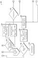
Fig. 7A, 7B, and 7C show an acceleration control process 200. At block 114 (as discussed above), controller 34 enters acceleration control (i.e., begins acceleration control process 200). The acceleration control process 200 then proceeds to block 202. At block 202, the controller 34 uses the predicted speed table PST to identify violations of the minimum allowable speed vminThe first speed point of (1). In other words, the controller 34 identifies less than the minimum allowable speed v in the predicted speed table PSTminThe first speed point of (1). After block 202, the acceleration control process 200 continues to block 204.
At block 204, beginning at the first speed point identified in block 202, the controller 34 moves forward in the predicted speed table PST untilv i+1>viIn order to find the first local minimum of the predicted speed. This first local minimum of predicted speed is referred to as the first local minimum of predicted speed during acceleration control 200v peak . After block 204, the method proceeds to block 206. First local minimum of predicted speedv peak May correspond to a local maximum altitude in the altitude prediction table EDT. Thus, the controller 34 also determines the local maximum altitude in the altitude prediction table EDT and its corresponding index in the altitude prediction table EDTi peak . Next, the acceleration control process 200 continues to block 206.
At block 206, the controller 34 determines the distance from the current position of the vehicle 10 to the local maximum altitude and its corresponding indexi peak And stores it in the altitude prediction table EDT. The distance from the current position of the vehicle 10 to the local maximum altitude is referred to as the peak distanced peak . After block 204, the acceleration control process 200 continues to block 208.
At block 208, controller 34 compares the peak distanced peak Is set to the minimum allowable speed vmin. After block 208, the acceleration control process 200 proceeds to block 210.
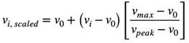
At block 210, the controller 34 calculates a scaled predicted speed schedule, such as the updated predicted speed schedule UPST shown in FIG. 5. To this end, the controller 34 may use the following equation:

wherein:
v 0 is the current speed of the vehicle 10;
v i is the vehicle 10 at the index pointiThe predicted speed of (d);
v min is the minimum allowable speed;
v peak is the first local minimum of the predicted speed determined in block 204; and
v i,scaled is the vehicle 10 at the index pointiThe expected speed of scaling at (a).
Using the above equation, the controller 34 generates a scaled predicted speed schedule. Thus, the controller 34 is based on the minimum allowable speedv min And a first local minimumv peak And a scaled predicted speed schedule is calculated. After block 210, the acceleration control process 200 proceeds to block 212.
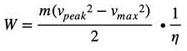
At block 212, controller 34 calculates the distance at the peakd peak To achieve a minimum allowable velocity vminThe required work input W. To this end, the controller 34 may use the following equation:
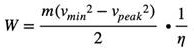
wherein:
mis the mass of the vehicle 10;
v peak is confirmed in block 204A first local minimum of the determined predicted speed;
η is a calibratable (and/or learned) engine-to-road efficiency factor;
v min is the minimum allowable speed;
Wis at the peak distanced peak To achieve a minimum allowable velocity vminThe required work input.
In determining the distance at the peakd peak To achieve a minimum allowable velocity vminAfter the requested work input W, the acceleration control process 200 proceeds to block 214.
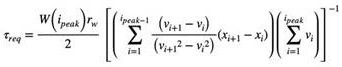
At block 214, controller 34 calculates the distance at the peak using the following equationd peak To achieve a minimum allowable velocity vminRequired (if continuously applied) adjustment torqueτ req :
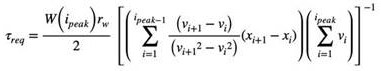
Wherein:
r w is the radius of one of the wheels 17 (i.e., the wheel radius);
v i is the index point in the scaled predicted velocity schedule generated in block 210iThe predicted speed of (d);
x i is an index point from the current position of the vehicle 10 into the scaled predicted speed schedule generated in block 210iThe distance of (d);
v i+1 is the index point in the scaled predicted velocity schedule generated in block 210iPredicted speed at + 1;
i peak is the first local minimum of the predicted speedv peak Index point (i.e., location);
i peak-1 is the first local minimum immediately following the predicted speedv peak Previous index points (i.e., locations); and
τ req is to achieve a driver defined speed minimum speed limit vminThe required (if continuously applied) adjustment torque.
At block 214, if the required work W is added to the system at a constant rate, the efficiency will be maximized. After block 214, the acceleration control process 200 proceeds to block 216.
At block 216, assume that the commanded axle torque remains constant at the peak distanced peak To achieve a minimum allowable velocity vminRequired (if continuously applied) adjustment torqueτ req At a set speed vssCommanded axle torque τ for road load torquessAnd then the controller 34 recalculates the predicted speedometer. After block 216, the acceleration control process 200 proceeds to block 218.
At block 218, controller 34 determines the distance at the peak valued peak Whether there were any speed violations before. If at peak distanced peak If there was a minimum speed violation, the acceleration control process 200 returns to block 202. If at peak distanced peak Before there is a maximum speed violation, controller 34 begins deceleration control process 300 at block 112 (fig. 8A, 8B, 8C, and 8D). If at peak distanced peak If there was no speed violation before, the acceleration control process 200 proceeds to block 220.
At block 220, controller 34 sets the commanded engine torque to be at the peak distanced peak To achieve a minimum allowable velocity vminRequired (if continuously applied) adjustment torqueτ req At a set speed vssLower pair road loadCommanded axle torque of torque τssAnd (4) summing. In addition, controller 34 commands propulsion system 20 to produce an updated commanded axle torque. This updated commanded axle torque may be equal to at peak distanced peak To achieve a minimum allowable velocity vminRequired (if continuously applied) adjustment torqueτ req Plus at a set speed vssCommanded axle torque τ for road load torquess. The acceleration control process 200 then proceeds to block 222.
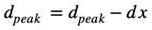
Between block 220 and block 222, the vehicle 10 travels to the predicted point x in the altitude prediction Table EDT1. At block 222, controller 34 sets the peak distance using the following equationd peak :
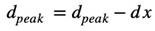
Wherein:
d peak is the peak distance; and
dxis a predicted point in the elevation prediction table EDTx 0And a predicted pointx 1The distance between them.
After block 222, the acceleration control process 200 proceeds to block 224.
At block 224, controller 34 determines the newly set peak distanced peak Whether less than zero. If the newly set peak distanced peak Not less than zero, the acceleration control process 200 returns to block 216. If the newly set peak distanced peak Less than zero, the acceleration control process 200 proceeds to block 226. At block 226, controller 34 exits acceleration control.
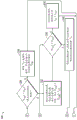
Fig. 8A, 8B, 8C, and 8D show a deceleration control process 300. At block 112 (as discussed above), controller 34 enters deceleration control (i.e., begins deceleration control process 300). The deceleration control process 300 then proceeds to block 302. At block 302, the controller 34 uses the predicted speed table PST to identify violations of the maximum allowable velocity vmaxThe first speed point of (1). In other words, the controller 34 identifies that the predicted speed table PST is greater than the maximum allowable speed vmaxThe first speed point of (1). After block 302, the deceleration control process 300 continues to block 304.
At block 304, beginning at the first speed point identified in block 302, the controller 34 moves forward in the predicted speed table PST untilv i+1<viIn order to find the first local maximum of the predicted speed. This first local maximum in predicted speed is referred to as the first local maximum in the deceleration control process 300v peak . After block 304, the method proceeds to block 306. First local maximum of predicted speedv peak May correspond to a local minimum altitude in the altitude prediction table EDT. Thus, the controller 34 also determines the local maximum altitude in the altitude prediction table EDT and its corresponding index in the altitude prediction table EDTi peak . Next, the deceleration control process 300 continues to block 306.
At block 306, the controller 34 determines the distance from the current position of the vehicle 10 to the local minimum altitude and its corresponding indexi peak And stores it in the altitude prediction table EDT. The distance from the current position of the vehicle 10 to the local minimum altitude is referred to as the peak distanced peak . After block 304, the deceleration control process 300 continues to block 308.
At block 308, controller 34 compares the peak distanced peak Is set to the maximum allowable speed vmax. After block 308, the deceleration control process 300 proceeds to block 310.
At block 310, the controller 34 calculates a scaled predicted speed schedule, such as the updated predicted speed schedule UPST shown in FIG. 5. To this end, the controller 34 may use the following equation:
wherein:
v 0 is the current speed of the vehicle 10;
v i is the vehicle 10 at the index pointiThe predicted speed of (d);
v max is the maximum allowable speed;
v peak is the first local maximum of the predicted speed determined in block 304; and
v i,scaled is the vehicle 10 at the index pointiThe expected speed of scaling at (a).
Using the above equation, the controller 34 generates a scaled predicted speed schedule. Thus, the controller 34 is based on the maximum allowable speedv max And a first local maximumv peak And a scaled predicted speed schedule is calculated. After block 310, the deceleration control process 300 proceeds to block 312.
At block 312, controller 34 calculates the distance at the peakd peak To achieve a maximum allowable velocity vmaxThe required work input W. To this end, the controller 34 may use the following equation:
wherein:
mis the mass of the vehicle 10;
v peak is the first local maximum of the predicted speed determined in block 304;
η is a calibratable engine-to-road efficiency factor;
v max is the maximum allowable speed;
Wis at the peakDistance of valued peak To achieve a maximum allowable velocity vmaxThe required work input.
In determining the distance at the peakd peak To achieve a maximum allowable velocity vmaxAfter the requested work input W, the deceleration control process 300 proceeds to block 314.
At block 314, controller 34 calculates the distance at the peak using the following equationd peak To achieve a maximum allowable velocity vmaxThe required (if continuously applied) adjustment torque is reducedτ req :
Wherein:
r w is the radius of one of the wheels 17 (i.e., the wheel radius);
v i is the index point in the scaled predicted velocity schedule generated in block 210iThe predicted speed of (d);
x i is an index point from the current position of the vehicle 10 into the scaled predicted speed schedule generated in block 210iThe distance of (d);
v i+1 is the index point in the scaled predicted velocity schedule generated in block 210iPredicted speed at + 1;
i peak is the first local minimum of the predicted speedv peak Index point (i.e., location);
i peak-1 is the first local minimum immediately following the predicted speedv peak Previous index points (i.e., locations); and
τ req is to achieve a maximum driver-defined speed limit vmaxThe required (if continuously applied) adjustment torque.
At block 314, if the required work W is added to the system at a constant rate, efficiency will be maximized. After block 314, the deceleration control process 300 proceeds to block 316.
At block 316, assume that the commanded axle torque remains constant at the peak distanced peak To achieve a maximum allowable velocity vmaxThe required (if continuously applied) adjustment torque is reducedτ req At a set speed vssCommanded axle torque τ for road load torquessAnd then the controller 34 recalculates the predicted speedometer. After block 318, the deceleration control process 300 proceeds to block 318.
At block 318, controller 34 determines the distance at the peakd peak Whether there were any speed violations before. If at peak distanced peak If there was a maximum speed violation, the deceleration control process 300 returns to block 302. If at peak distanced peak With the minimum speed violation, controller 34 begins acceleration control process 200 at block 114 (fig. 7A, 7B, and 7C). If at peak distanced peak If there was no speed violation before, the deceleration control process 300 proceeds to block 320.
At block 320, the controller 34 will be at the peak distanced peak To achieve a maximum allowable velocity vmaxThe required (if continuously applied) adjustment torque is reducedτ req Is compared to the absolute value of the torque necessary to operate the air conditioning system 29 (i.e., the maximum alternator torque). If at peak distanced peak To achieve a maximum allowable velocity vmaxThe required (if continuously applied) adjustment torque is reducedτ req Is greater than the absolute value of the torque necessary to operate air conditioning system 29, then the deceleration control process 300 proceeds to block 322. If at the peakDistance of valued peak To achieve a maximum allowable velocity vmaxThe required (if continuously applied) adjustment torque is reducedτ req Is not greater than the absolute value of the torque necessary to operate the air conditioning system 29, the deceleration control process 300 proceeds to block 324.
At block 324, controller 34 maintains commanded axle torque τss. In addition, providing at peak distance via battery regenerationd peak To achieve a maximum allowable velocity vmaxThe required (if continuously applied) adjustment torque is reducedτ req . In battery regeneration, the propulsion system 20 charges the battery 21 of the vehicle 10. After block 324, the deceleration control process 300 proceeds to block 340.
At block 340, the vehicle 10 travels to the predicted point x in the altitude prediction Table EDT1. After block 340, the deceleration control process 300 proceeds to block 342.
At block 342, controller 34 sets the peak distance using the following equationd peak :
Wherein:
d peak is the peak distance; and
dxis a predicted point in the elevation prediction table EDTx 0And a predicted pointx 1The distance between them.
After block 342, the deceleration control process 300 proceeds to block 344.
At block 344, controller 34 determines the newly set peak distanced peak Whether less than zero. If the newly set peak distanced peak Not less than zero, the deceleration control process 300 returns to block 316. If the newly set peak distanced peak Less than zero, the deceleration control process 300 proceeds to block 346. At block 346, the controller34 exit the deceleration control.
At block 322, controller 34 commands propulsion system 20 to engage in maximum battery regeneration. In maximum battery regeneration, the propulsion system 20 charges the battery 21 of the vehicle 10. In the second deceleration mode, propulsion system 20 drives compressor 31 of air conditioning system 29. At block 322, the controller 34 will be at the peak distanced peak To achieve a maximum allowable velocity vmaxThe required (if continuously applied) adjustment torque is reducedτ req Is set equal to the distance at the peakd peak To achieve a maximum allowable velocity vmaxThe required (if continuously applied) adjustment torque is reducedτ req Minus the torque necessary to operate the air conditioning system 29. After block 322, the deceleration control process 300 proceeds to block 326.
At block 326, controller 34 determines whether air conditioning system 29 is on. If air conditioning system 29 is on, then deceleration control process 300 proceeds to block 328. If air conditioning system 29 is off, then deceleration control process 300 proceeds to block 330.
At block 328, the controller 34 will be at the peak distanced peak To achieve a maximum allowable velocity vmaxRequired (if continuously applied) new set adjustment torque reductionτ req Is compared to the absolute value of the torque necessary to operate the air conditioning system 29 (i.e., the maximum a/C compressor torque). The maximum a/C compressor torque is the maximum torque required to operate the compressor 31 of the air conditioning system 29. If at peak distanced peak To achieve a maximum allowable velocity vmaxThe required (if continuously applied) adjustment torque is reducedτ req Is greater than the absolute value of the torque necessary to operate air conditioning system 29, then the deceleration control process 300 proceeds to block 332. If at peak distanced peak To achieve a maximum allowable velocity vmaxThe required (if continuously applied) adjustment torque is reducedτ req Is not greater than the absolute value of the torque necessary to operate the air conditioning system 29, is decreasedThe speed control process 300 proceeds to block 334.
At block 332, the controller 34 sets the maximum a/C compressor load to the maximum value for the current climate setting. At block 332, the controller 34 will be at the peak distanced peak To achieve a maximum allowable velocity vmaxRequired (if continuously applied) new set adjustment torque reductionτ req Is set equal to the distance at the peakd peak To achieve a maximum allowable velocity vmaxThe required (if continuously applied) adjustment torque is reducedτ req Minus the maximum torque required to operate the compressor 31 of the air conditioning system 29. After block 332, the deceleration control process 300 proceeds to block 330.
At block 334, controller 34 maintains commanded axle torque τss. Further, the peak distance is provided via the A/C compressor load (i.e., the load of the compressor 31 of the air conditioning system 29)d peak To achieve a maximum allowable velocity vmaxThe required (if continuously applied) adjustment torque is reducedτ req . After block 334, the deceleration control process 300 proceeds to block 340.
At block 330, the controller 34 will be at the peak distanced peak To achieve a maximum allowable velocity vmaxRequired (if continuously applied) new set adjustment torque reductionτ req Is compared with the absolute value of the torque necessary to operate the air conditioning system 29. If at peak distanced peak To achieve a maximum allowable velocity vmaxRequired (if continuously applied) new set adjustment torque reductionτ req Is greater than the absolute value of the torque necessary to operate the air conditioning system 29, the deceleration control process 300 proceeds to block 336. If at peak distanced peak To achieve a maximum allowable velocity vmaxRequired (if continuously applied) new set adjustment torque reductionτ req Is not greater than the absolute value of the torque necessary to operate the air conditioning system 29,the deceleration control process 300 proceeds to block 338.
At block 336, the controller 34 sets the virtual pedal input to zero (tip out). In other words, controller 34 commands propulsion system 20 to produce zero torque. At block 336, controller 34 commands brake system 26 to actuate to provide the remaining commanded axle torque τss. After block 336, the deceleration control process 300 proceeds to block 340.
At block 338, controller 34 sets the commanded engine torque to be at the peak distanced peak To achieve a maximum allowable velocity vmaxThe required (if continuously applied) adjustment torque is reducedτ req At a set speed vssCommanded axle torque τ for road load torquessAnd (4) summing. In other words, controller 34 commands propulsion system 20 to reduce the commanded axle torque to be at the peak distanced peak To achieve a maximum allowable velocity vmaxThe required (if continuously applied) adjustment torque is reducedτ req At a set speed vssCommanded axle torque τ for road load torquessAnd (4) summing. After block 338, the deceleration control process 300 proceeds to block 340.
The detailed description and drawings or illustrations are supportive and descriptive of the present teachings, but the scope of the present teachings is limited only by the claims. While the best modes and some of the other embodiments for carrying out the present teachings have been described in detail, various alternative designs and embodiments exist for practicing the present teachings as defined in the appended claims.
Claims (10)
1. Cruise control method for controlling a vehicle, comprising:
receiving, by a controller of the vehicle, a set speed, a maximum allowed speed, and a minimum allowed speed, wherein each of the maximum allowed speed and the minimum allowed speed is a speed boundary of an allowed speed range;
commanding, by the controller, a propulsion system to produce a commanded axle torque to maintain the set speed;
monitoring a current speed of the vehicle;
monitoring an elevation of terrain at a predetermined upcoming location of the vehicle based on upcoming elevation data;
generating an altitude prediction table using the altitude of the terrain at the predetermined upcoming location of the vehicle, wherein the altitude prediction table includes a plurality of predicted altitude points;
determining a projected speed of the vehicle at each of the predetermined upcoming positions of the vehicle as a function of the current speed of the vehicle and the elevation of the terrain at the predetermined upcoming positions of the vehicle;
generating a projected speed schedule using the projected speeds of the vehicle at each of the predetermined upcoming locations of the vehicle;
comparing each of the expected speeds of the vehicle at each of the predetermined upcoming locations to the allowable speed range;
determining whether at least one of the projected speeds is outside of the allowable speed range; and
commanding, by the controller, the propulsion system of the vehicle to adjust the commanded axle torque in order to maintain the actual speed of the vehicle within the allowable speed range at each of the predetermined upcoming positions in response to determining that at least one of the projected speeds is outside the allowable speed range.
2. The cruise control method according to claim 1, further comprising: a first speed point in the predicted speed schedule that is less than the minimum allowable speed is identified.
3. The cruise control method according to claim 2, further comprising: a first local minimum in the predicted speed schedule is sought.
4. The cruise control method according to claim 3, further comprising: determining a distance from a current position of the vehicle to a position at the first local minimum, wherein the distance from the current position of the vehicle to the position at the first local minimum is a peak distance.
5. The cruise control method according to claim 4, further comprising: setting the desired speed at the peak distance to the minimum allowable speed.
6. The cruise control method according to claim 5, further comprising: a scaled predicted speed schedule is calculated based on the minimum allowable speed and the first local minimum.
7. The cruise control method according to claim 6, further comprising: calculating a work input required to achieve the minimum allowable speed at the peak distance based on the mass of the vehicle and the minimum allowable speed.
8. The cruise control method according to claim 7, further comprising: calculating, from the requested work input, an adjustment torque required to achieve the minimum allowable speed at the peak distance.
9. The cruise control method according to claim 8, further comprising: recalculating the predicted speed schedule based on the trim torque required to achieve the minimum allowable speed at the peak distance.
10. The cruise control method according to claim 9, further comprising: commanding the propulsion system to produce an updated commanded axle torque, wherein the updated commanded axle torque is equal to the adjustment torque required to achieve the minimum allowable speed at the peak distance plus the commanded axle torque.
Applications Claiming Priority (2)
| Application Number | Priority Date | Filing Date | Title |
|---|---|---|---|
| US16/444,628 US11052896B2 (en) | 2019-06-18 | 2019-06-18 | Predictive grade optimization in cruise control |
| US16/444628 | 2019-06-18 |
Publications (2)
| Publication Number | Publication Date |
|---|---|
| CN112092811A true CN112092811A (en) | 2020-12-18 |
| CN112092811B CN112092811B (en) | 2024-01-16 |
Family
ID=73750124
Family Applications (1)
| Application Number | Title | Priority Date | Filing Date |
|---|---|---|---|
| CN202010560116.6A Active CN112092811B (en) | 2019-06-18 | 2020-06-18 | Predicted gradient optimization in cruise control |
Country Status (2)
| Country | Link |
|---|---|
| US (1) | US11052896B2 (en) |
| CN (1) | CN112092811B (en) |
Families Citing this family (2)
| Publication number | Priority date | Publication date | Assignee | Title |
|---|---|---|---|---|
| US11702090B2 (en) * | 2019-08-06 | 2023-07-18 | Nissan North America | System for an automated vehicle |
| KR20210155262A (en) * | 2020-06-15 | 2021-12-22 | 현대자동차주식회사 | Apparatus controlling a vehicle based on precise loadlevel using GPS, system having the same and method thereof |
Citations (10)
| Publication number | Priority date | Publication date | Assignee | Title |
|---|---|---|---|---|
| CN102381315A (en) * | 2010-08-24 | 2012-03-21 | 通用汽车环球科技运作有限责任公司 | Method for preventing activation of resume function in a cruise control system |
| CN102470867A (en) * | 2009-07-02 | 2012-05-23 | 沃尔沃拉斯特瓦格纳公司 | Method and system for controlling a vehicle cruise control |
| CN102781708A (en) * | 2009-12-21 | 2012-11-14 | 沃尔沃拉斯特瓦格纳公司 | Method and system for controlling a vehicle cruise control |
| CN104010861A (en) * | 2011-12-22 | 2014-08-27 | 斯堪尼亚商用车有限公司 | Method and module for determining of at least one reference value |
| US20160009278A1 (en) * | 2013-03-21 | 2016-01-14 | Scania Cv Ab | Method for controlling an actual speed of a vehicle |
| CN105270401A (en) * | 2014-07-11 | 2016-01-27 | 福特全球技术公司 | Adjusting a hybrid vehicle cruise control speed |
| US20160297435A1 (en) * | 2015-04-13 | 2016-10-13 | Ford Global Technologies, Llc | Method and system for vehicle cruise control |
| US20170129492A1 (en) * | 2015-11-09 | 2017-05-11 | Cummins Inc. | Systems and methods for pre-hill cruise speed adjustment |
| US20170291605A1 (en) * | 2016-04-12 | 2017-10-12 | GM Global Technology Operations LLC | Optimized fuel economy during cruise control using topography data |
| BR112012028124A2 (en) * | 2010-05-03 | 2018-05-22 | Volvo Lastvagnar Ab | Method and device for controlling a cruise control manager in a vehicle |
Family Cites Families (6)
| Publication number | Priority date | Publication date | Assignee | Title |
|---|---|---|---|---|
| US6374173B1 (en) | 1999-05-28 | 2002-04-16 | Freightliner Llc | Terrain adaptive cruise control |
| US6990401B2 (en) | 2002-10-04 | 2006-01-24 | Daimlerchrysler Ag | Predictive speed control for a motor vehicle |
| US8712650B2 (en) * | 2005-11-17 | 2014-04-29 | Invent.Ly, Llc | Power management systems and designs |
| US20110276216A1 (en) | 2010-05-07 | 2011-11-10 | Texas Instruments Incorporated | Automotive cruise controls, circuits, systems and processes |
| GB2552021B (en) * | 2016-07-08 | 2019-08-28 | Jaguar Land Rover Ltd | Improvements in vehicle speed control |
| US10040453B2 (en) * | 2016-11-17 | 2018-08-07 | Toyota Motor Engineering & Manufacturing North America, Inc. | Systems and methods for preemptively modifying vehicle parameters according to predicted accelerations upon a travel lane clearing |
-
2019
- 2019-06-18 US US16/444,628 patent/US11052896B2/en active Active
-
2020
- 2020-06-18 CN CN202010560116.6A patent/CN112092811B/en active Active
Patent Citations (11)
| Publication number | Priority date | Publication date | Assignee | Title |
|---|---|---|---|---|
| CN102470867A (en) * | 2009-07-02 | 2012-05-23 | 沃尔沃拉斯特瓦格纳公司 | Method and system for controlling a vehicle cruise control |
| US20130030668A1 (en) * | 2009-07-02 | 2013-01-31 | Volvo Lastvagnar Ab | Method and system for controlling a vehicle cruise control |
| CN102781708A (en) * | 2009-12-21 | 2012-11-14 | 沃尔沃拉斯特瓦格纳公司 | Method and system for controlling a vehicle cruise control |
| BR112012028124A2 (en) * | 2010-05-03 | 2018-05-22 | Volvo Lastvagnar Ab | Method and device for controlling a cruise control manager in a vehicle |
| CN102381315A (en) * | 2010-08-24 | 2012-03-21 | 通用汽车环球科技运作有限责任公司 | Method for preventing activation of resume function in a cruise control system |
| CN104010861A (en) * | 2011-12-22 | 2014-08-27 | 斯堪尼亚商用车有限公司 | Method and module for determining of at least one reference value |
| US20160009278A1 (en) * | 2013-03-21 | 2016-01-14 | Scania Cv Ab | Method for controlling an actual speed of a vehicle |
| CN105270401A (en) * | 2014-07-11 | 2016-01-27 | 福特全球技术公司 | Adjusting a hybrid vehicle cruise control speed |
| US20160297435A1 (en) * | 2015-04-13 | 2016-10-13 | Ford Global Technologies, Llc | Method and system for vehicle cruise control |
| US20170129492A1 (en) * | 2015-11-09 | 2017-05-11 | Cummins Inc. | Systems and methods for pre-hill cruise speed adjustment |
| US20170291605A1 (en) * | 2016-04-12 | 2017-10-12 | GM Global Technology Operations LLC | Optimized fuel economy during cruise control using topography data |
Also Published As
| Publication number | Publication date |
|---|---|
| US20200398810A1 (en) | 2020-12-24 |
| US11052896B2 (en) | 2021-07-06 |
| CN112092811B (en) | 2024-01-16 |
Similar Documents
| Publication | Publication Date | Title |
|---|---|---|
| CN109383505B (en) | System and method for determining efficient driving speed of vehicle | |
| CN108058704B (en) | Predictive control of a powertrain system based on vehicle-to-vehicle communication | |
| US10099702B2 (en) | Method and apparatus for vehicle accessory and load management | |
| EP2794379B1 (en) | Method and module for controlling a vehicle's speed based on rules and/or costs | |
| CN106004875A (en) | Adaptive cruise control system | |
| US20190248364A1 (en) | Methods and systems for road hazard detection and localization | |
| CN107021100B (en) | Systems and methods for uphill speed assist | |
| CN111409621B (en) | System and method for torque distribution arbitration | |
| CN113525373B (en) | Lane changing control system, control method and lane changing controller for vehicle | |
| CN113492860B (en) | Driving performance adjusting method and device | |
| EP2219092B1 (en) | Method for controlling the speed of a vehicle | |
| CN112423228A (en) | System and method for vehicle routing | |
| CN112092811B (en) | Predicted gradient optimization in cruise control | |
| CN111605550A (en) | Ecological cruising: fuel-economy optimized cruise control | |
| CN111688685B (en) | Ecological cruising: torque management | |
| CN111532284B (en) | Device for enabling user driving range and feature selection | |
| US11364908B2 (en) | Automatic following distance in cruise control | |
| EP4337507A1 (en) | A method for controlling a vehicle | |
| US20240075930A1 (en) | Driver assistance for high accelleration and speed on a minimum time path | |
| US20230339470A1 (en) | Systems and methods for implementing a lane change in response to a closed lane segment | |
| US20230278562A1 (en) | Method to arbitrate multiple automatic lane change requests in proximity to route splits | |
| US11794777B1 (en) | Systems and methods for estimating heading and yaw rate for automated driving | |
| CN114987443B (en) | Wheel slip rate control method, device, vehicle and storage medium | |
| SE2250483A1 (en) | Method and control arrangement for controlling a vehicle during a speed reduction | |
| CN117087667A (en) | Adaptive cruise control with load |
Legal Events
| Date | Code | Title | Description |
|---|---|---|---|
| PB01 | Publication | ||
| PB01 | Publication | ||
| SE01 | Entry into force of request for substantive examination | ||
| SE01 | Entry into force of request for substantive examination | ||
| GR01 | Patent grant | ||
| GR01 | Patent grant |