CN111889274A - Glass lining reaction kettle coating device - Google Patents
Glass lining reaction kettle coating device Download PDFInfo
- Publication number
- CN111889274A CN111889274A CN202010768875.1A CN202010768875A CN111889274A CN 111889274 A CN111889274 A CN 111889274A CN 202010768875 A CN202010768875 A CN 202010768875A CN 111889274 A CN111889274 A CN 111889274A
- Authority
- CN
- China
- Prior art keywords
- reaction kettle
- coating device
- transmission
- bevel gear
- column
- Prior art date
- Legal status (The legal status is an assumption and is not a legal conclusion. Google has not performed a legal analysis and makes no representation as to the accuracy of the status listed.)
- Pending
Links
Images


Classifications
-
- B—PERFORMING OPERATIONS; TRANSPORTING
- B05—SPRAYING OR ATOMISING IN GENERAL; APPLYING FLUENT MATERIALS TO SURFACES, IN GENERAL
- B05B—SPRAYING APPARATUS; ATOMISING APPARATUS; NOZZLES
- B05B13/00—Machines or plants for applying liquids or other fluent materials to surfaces of objects or other work by spraying, not covered by groups B05B1/00 - B05B11/00
- B05B13/06—Machines or plants for applying liquids or other fluent materials to surfaces of objects or other work by spraying, not covered by groups B05B1/00 - B05B11/00 specially designed for treating the inside of hollow bodies
- B05B13/0645—Machines or plants for applying liquids or other fluent materials to surfaces of objects or other work by spraying, not covered by groups B05B1/00 - B05B11/00 specially designed for treating the inside of hollow bodies the hollow bodies being rotated during treatment operation
- B05B13/0654—Machines or plants for applying liquids or other fluent materials to surfaces of objects or other work by spraying, not covered by groups B05B1/00 - B05B11/00 specially designed for treating the inside of hollow bodies the hollow bodies being rotated during treatment operation and a treating nozzles being translated through the hollow bodies in a direction essentially parallel to the rotational axis
-
- B—PERFORMING OPERATIONS; TRANSPORTING
- B05—SPRAYING OR ATOMISING IN GENERAL; APPLYING FLUENT MATERIALS TO SURFACES, IN GENERAL
- B05B—SPRAYING APPARATUS; ATOMISING APPARATUS; NOZZLES
- B05B13/00—Machines or plants for applying liquids or other fluent materials to surfaces of objects or other work by spraying, not covered by groups B05B1/00 - B05B11/00
- B05B13/06—Machines or plants for applying liquids or other fluent materials to surfaces of objects or other work by spraying, not covered by groups B05B1/00 - B05B11/00 specially designed for treating the inside of hollow bodies
- B05B13/0627—Arrangements of nozzles or spray heads specially adapted for treating the inside of hollow bodies
- B05B13/0636—Arrangements of nozzles or spray heads specially adapted for treating the inside of hollow bodies by means of rotatable spray heads or nozzles
-
- B—PERFORMING OPERATIONS; TRANSPORTING
- B05—SPRAYING OR ATOMISING IN GENERAL; APPLYING FLUENT MATERIALS TO SURFACES, IN GENERAL
- B05B—SPRAYING APPARATUS; ATOMISING APPARATUS; NOZZLES
- B05B16/00—Spray booths
- B05B16/20—Arrangements for spraying in combination with other operations, e.g. drying; Arrangements enabling a combination of spraying operations
-
- B—PERFORMING OPERATIONS; TRANSPORTING
- B05—SPRAYING OR ATOMISING IN GENERAL; APPLYING FLUENT MATERIALS TO SURFACES, IN GENERAL
- B05C—APPARATUS FOR APPLYING FLUENT MATERIALS TO SURFACES, IN GENERAL
- B05C1/00—Apparatus in which liquid or other fluent material is applied to the surface of the work by contact with a member carrying the liquid or other fluent material, e.g. a porous member loaded with a liquid to be applied as a coating
- B05C1/02—Apparatus in which liquid or other fluent material is applied to the surface of the work by contact with a member carrying the liquid or other fluent material, e.g. a porous member loaded with a liquid to be applied as a coating for applying liquid or other fluent material to separate articles
- B05C1/022—Apparatus in which liquid or other fluent material is applied to the surface of the work by contact with a member carrying the liquid or other fluent material, e.g. a porous member loaded with a liquid to be applied as a coating for applying liquid or other fluent material to separate articles to the outer surface of hollow articles
-
- B—PERFORMING OPERATIONS; TRANSPORTING
- B05—SPRAYING OR ATOMISING IN GENERAL; APPLYING FLUENT MATERIALS TO SURFACES, IN GENERAL
- B05C—APPARATUS FOR APPLYING FLUENT MATERIALS TO SURFACES, IN GENERAL
- B05C13/00—Means for manipulating or holding work, e.g. for separate articles
- B05C13/02—Means for manipulating or holding work, e.g. for separate articles for particular articles
-
- B—PERFORMING OPERATIONS; TRANSPORTING
- B05—SPRAYING OR ATOMISING IN GENERAL; APPLYING FLUENT MATERIALS TO SURFACES, IN GENERAL
- B05C—APPARATUS FOR APPLYING FLUENT MATERIALS TO SURFACES, IN GENERAL
- B05C9/00—Apparatus or plant for applying liquid or other fluent material to surfaces by means not covered by any preceding group, or in which the means of applying the liquid or other fluent material is not important
- B05C9/08—Apparatus or plant for applying liquid or other fluent material to surfaces by means not covered by any preceding group, or in which the means of applying the liquid or other fluent material is not important for applying liquid or other fluent material and performing an auxiliary operation
- B05C9/14—Apparatus or plant for applying liquid or other fluent material to surfaces by means not covered by any preceding group, or in which the means of applying the liquid or other fluent material is not important for applying liquid or other fluent material and performing an auxiliary operation the auxiliary operation involving heating or cooling
Landscapes
- Physical Or Chemical Processes And Apparatus (AREA)
Abstract
The invention relates to the field of glass lining reaction kettles, in particular to a coating device of a glass lining reaction kettle. The technical problem of the invention is as follows: provides a coating device of a glass lining reaction kettle. The technical scheme is as follows: a glass lining reaction kettle coating device comprises a treatment area outer cover, a reaction kettle inner lower half area coating device, a reaction kettle outer coating device and the like; the rear middle part of the reaction kettle outer coating device is connected with the reaction kettle inner lower half area coating device; the middle part of the inner top of the treatment area outer cover is connected with the upper half area coating device in the reaction kettle through bolts. The invention achieves the purposes of uniformly covering the porcelain glaze to the areas with different heights of the lower semi-curved surface by using centrifugal force and reducing the consumption; the problem that the width of the brush is too large, the two sides of the brush hair cannot be contacted with the surface due to the curved surface, and the work can be finished only by brushing for multiple times is solved; and the porcelain glaze is sprayed to the upper hemispherical surface of the inner spherical surface, so that the effect of quickly processing the inner upper half curved surface dead angle is achieved.
Description
Technical Field
The invention relates to the field of glass lining reaction kettles, in particular to a coating device of a glass lining reaction kettle.
Background
The enamel glass is prepared by coating enamel with high silicon content on the surface of metal, drying the enamel, and enameling at 950 ℃ to make the enamel adhere to the surface of the metal iron core. Thus, it has the dual advantages of chemical stability and metal strength similar to glass.
Most of the prior enamel glaze coating work on the surface of the glass lining reaction kettle depends on manual treatment. The laboratory needs to utilize a sphere glass lining reaction kettle to heat some toxic and corrosive liquid substances and is limited by space, the volume of the sphere glass lining reaction kettle for the laboratory is generally small, when an original sphere metal container is subjected to enamel coating work, particularly when enamel is adhered to the inner surface of a sphere small instrument, because the inner space of the container is narrow, the space which can be touched by the hands of workers is limited, a plurality of dead corners which cannot be processed or have extremely low processing speed exist, a large amount of time is consumed for processing the positions, and the processing efficiency is not high enough; the glaze covering work can be rapidly carried out by directly filling the container with the glaze, but the consumption of the glaze is greatly increased, the cost is high, and most of the glaze is directly wasted; workers are in contact with the porcelain glaze liquid for a long time every day, and the health of the workers is influenced after the years.
In summary, there is a need to develop a device capable of quickly and automatically glazing the interior of a sphere container under the condition of low enamel consumption, reducing the contact time between workers and enamel, and protecting the health of the workers, so as to overcome the defects of long glazing time, high enamel consumption and easy chronic diseases caused by long-time contact of the workers with the enamel in the prior art.
Disclosure of Invention
In order to overcome the defects of long glazing time, large enamel consumption and easy chronic diseases caused by long-time contact of workers with the enamel in the prior art, the invention has the technical problems that: provides a coating device of a glass lining reaction kettle.
The technical scheme is as follows: a coating device of a glass lining reaction kettle comprises a workbench, a control screen, a treatment area outer cover, a coating device of the inner lower half area of the reaction kettle, an outer coating device of the reaction kettle, a coating device of the inner upper half area of the reaction kettle and a reaction kettle to be coated; a control screen is arranged on the middle left side of the top middle part of the workbench; the left side of the middle part of the top of the workbench is welded with the outer cover of the treatment area; the bottom in the workbench is provided with a coating device at the lower half area in the reaction kettle; the right side of the middle part of the top of the workbench is provided with a reaction kettle outer coating device, and the rear middle part of the reaction kettle outer coating device is connected with a coating device in the lower half area in the reaction kettle; the middle part of the inner top of the treatment area outer cover is connected with the upper half area coating device in the reaction kettle through a bolt, and the right side of the bottom of the upper half area coating device in the reaction kettle is connected with the lower half area coating device in the reaction kettle; the left side of the top of the coating device in the lower half area in the reaction kettle is sleeved with the reaction kettle to be coated.
In addition, particularly preferably, the coating device in the lower half area of the reaction kettle comprises a motor, a first bevel gear, a second bevel gear, a telescopic rod, a first straight gear, a control plate, a first electric push rod, a multi-layer fluted disc, a third bevel gear, a fourth bevel gear, a first transmission wheel, a second transmission wheel, a bearing chassis, a first annular slide rail and a reaction kettle base; the left end axis of the motor is in transmission connection with the first bevel gear; the right rear side of the first bevel gear is meshed with the second bevel gear; the left end axis of the first bevel gear is in transmission connection with the telescopic rod; the left end axis of the telescopic rod is in transmission connection with the first straight gear; the left side of the outer surface of the telescopic rod is sleeved with the control plate; the middle part of the right bottom of the control plate is in transmission connection with a first electric push rod; the rear side of the first straight gear is meshed with the multi-layer fluted disc; the left side of the multi-layer fluted disc is in transmission connection with a third bevel gear; the front top of the third bevel gear is meshed with the fourth bevel gear; the top end axis of the fourth bevel gear is in transmission connection with the first transmission wheel; the right side of the first driving wheel is in transmission connection with a second driving wheel; the axle center at the top end of the first transmission wheel is in transmission connection with the bearing chassis; the bottom of the bearing chassis is connected with the first annular slide rail in a sliding manner; the top end of the bearing chassis is connected with the reaction kettle base through a bolt; the axle center at the rear end of the second bevel gear is connected with a reaction kettle outer coating device; the bottom end of the motor is connected with the workbench; the top end of the second driving wheel is connected with the coating device in the upper half area in the reaction kettle; the bottom end of the first annular slide rail is connected with the workbench; the inner surface of the reaction kettle base is connected with a reaction kettle to be coated.
In addition, particularly preferably, the reaction kettle outer coating device comprises a transmission disc, a limiting transmission block, a transmission frame, a first transmission column, an outer layer brush, a limiting hole column, an anti-release disc, a track groove, a second transmission column, a tilting column, a torque spring, an intermittent motion cylindrical disc, a bearing base and a sliding base plate; the middle part of the front bottom of the transmission disc is welded with the limiting transmission block; the outer surface of the limiting transmission block is in transmission connection with the transmission frame; the middle of the top of the transmission frame is welded with the first transmission column; the left side of the middle part of the bottom of the transmission frame is in transmission connection with the second transmission column; the top end of the first transmission column is in transmission connection with the outer layer brush; the middle of the top of the outer surface of the first transmission column is in sliding connection with the limiting hole column; the right side of the front middle part of the outer layer brush is connected with the anti-falling disc through a bolt; the middle part of the outer surface of the anti-falling disc is in sliding connection with the track groove; the bottom end of the second transmission column is in transmission connection with the tilting column; the middle part of the outer surface of the seesaw column is sleeved with the torque spring; the front side of the left top of the tilting column is in transmission connection with the intermittent cylindrical disc; the top of the axis of the intermittent cylindrical disc is in transmission connection with the bearing base; the bottom of the bearing base is connected with the sliding chassis in a sliding manner; the axle center at the rear end of the transmission disc is connected with a second bevel gear; the bottom of the sliding chassis is connected with the workbench.
In addition, particularly preferably, the coating device in the upper half area in the reaction kettle comprises a second straight gear, an outer sleeve long gear, a spray pipe, a spray nozzle, a suspension plate, a second annular slide rail, a first slide rail hanging and clamping block, a first hydraulic rod, a second slide rail hanging and clamping block and a second hydraulic rod; an outer sleeve long gear is arranged at the left front upper part of the second straight gear; the inner middle part of the outer sleeve long gear is sleeved with the spray pipe; the left bottom of the spray pipe is sleeved with the nozzle; the top of the outer surface of the spray pipe is sleeved with the suspension plate; the middle part of the top of the suspension plate is welded with the second annular slide rail; the left side of the middle part of the top of the second annular slide rail is in sliding connection with the first slide rail hanging clamping block; the right side of the middle part of the top of the second annular slide rail is in sliding connection with a second slide rail hanging clamping block; the middle of the top of the first slide rail lifting clamping block is in transmission connection with a first hydraulic rod; the middle of the top of the second sliding rail hoisting clamping block is in transmission connection with a second hydraulic rod; the bottom end axis of the second straight gear is connected with a second transmission wheel; the top of the first hydraulic rod is connected with the processing area outer cover; the top of the second hydraulic rod is connected with the treatment area outer cover.
In addition, it is particularly preferable that the seesaw column comprises a main rod, a first balance seesaw, a second balance seesaw and a third balance seesaw; the right side of the rear middle part of the main rod is mutually inserted with the first balance wane; the left side of the front middle part of the main rod is mutually inserted with the second balance wane; the front end of the second balance warping plate is rotatably connected with the third balance warping plate.
In addition, it is particularly preferred that a unidirectional rotation axis is provided between the second and third rocker, which rotation axis enables the third rocker to rotate in an upward direction towards the second rocker.
In addition, it is particularly preferred that the front end of the multi-layer fluted disc is provided with three circles of teeth, and the teeth are arranged from outside to inside at equal intervals.
In addition, it is particularly preferred that a recess is provided in the middle of the outer brush base and into which the first drive rod can project.
The invention has the following advantages: in order to solve the problems that in the prior art, the glaze covering time is long, the consumption of the glaze is high, and workers are easy to suffer from chronic diseases when contacting the glaze for a long time, a lower half area coating device in a reaction kettle, a reaction kettle external coating device and an upper half area coating device in the reaction kettle are designed.
1. Through the coating device in the lower half area in the reaction kettle, centrifugal force and variable speed can be utilized to be mutually matched, under the condition that the enamel consumption is low, the enamel is uniformly covered to the areas with different heights of the lower half curved surface of the inner surface of the sphere of the reaction kettle, the unqualified corrosion resistance and temperature change resistance in the reaction kettle caused by uneven coating are avoided, the product quality is improved, the enamel consumption is reduced, and the treatment cost is reduced.
2. Through reation kettle external coating device, use the less brush head of width and less rotation to replace big brush head and big angle rotation, when having solved brush width too big, the radian of curved surface can lead to the left and right sides of brush hair face unable and surface in close contact with, in addition great turned angle, lead to only central authorities to apply paint the relatively intact that the region can be applied paint with a brush, what the left and right sides can not be fine applies paint with a brush, cause a reation kettle need apply paint with a brush repeatedly and can thoroughly accomplish the work of applying paint with a brush many times, the problem that work efficiency is extremely low, and the work efficiency is greatly improved.
3. Through the coating device in the upper half area in the reaction kettle, the enamel can be sprayed to the upper hemispherical surface of the inner spherical surface through mechanical transmission, the upper half curved surface dead angle which is difficult to reach by hands inside workers is replaced to be quickly processed by the enamel, and the working efficiency is improved.
Drawings
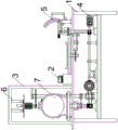
FIG. 1 is a schematic structural view of the present invention;
FIG. 2 is a schematic structural view of a lower half-zone coating device in a reaction kettle according to the present invention;
FIG. 3 is a schematic structural diagram of an external coating device of a reaction kettle according to the present invention;
FIG. 4 is a schematic structural view of a coating apparatus in the upper half of the reaction vessel according to the present invention;
FIG. 5 is a schematic structural view of a seesaw column according to the present invention;
FIG. 6 is an enlarged structural view of the region A of the present invention.
In the figure: 1: workbench, 2: control screen, 3: treatment area housing, 4: coating device for the lower half area in reaction kettle, 5: outer coating device of reaction kettle, 6: coating device for upper half area in reaction kettle, 7: to-be-coated reaction kettle, 401: motor, 402: first bevel gear, 403: second bevel gear, 404: telescopic rod, 405: first straight gear, 406: control board, 407: first electric putter, 408: multilayer fluted disc, 409: third bevel gear, 4010: fourth bevel gear, 4011: first drive wheel, 4012: second drive wheel, 4013: bearing chassis, 4014: first annular slide rail, 4015: reaction kettle base, 501: drive disk, 502: limiting transmission block, 503: transmission frame, 504: first drive column, 505: outer layer brush, 506: spacing hole post, 507: run-off prevention pan, 508: track slot, 509: second drive column, 5010: seesaw column, 5011: torque spring, 5012: intermittent cylindrical disc, 5013: bearing base, 5014: sliding chassis, 601: second spur gear, 602: jacket long gear, 603: nozzle, 604: nozzle, 605: suspension plate, 606: second annular slide rail, 607: first slide rail hanger clamp block, 608: first hydraulic rod, 609: second slide rail hanger clamp, 6010: second hydraulic lever, 501001: main rod, 501002: first counterbalanced paddle, 501003: second counterbalanced paddle, 501004: a third balanced paddle.
Detailed Description
Reference herein to an embodiment means that a particular feature, structure, or characteristic described in connection with the embodiment can be included in at least one embodiment of the invention. The appearances of the phrase in various places in the specification are not necessarily all referring to the same embodiment, nor are separate or alternative embodiments mutually exclusive of other embodiments. It is explicitly and implicitly understood by one skilled in the art that the embodiments described herein can be combined with other embodiments.
Example 1
A glass lining reaction kettle coating device is shown in figures 1-6 and comprises a workbench 1, a control screen 2, a treatment area outer cover 3, a reaction kettle inner lower half area coating device 4, a reaction kettle outer coating device 5, a reaction kettle inner upper half area coating device 6 and a reaction kettle 7 to be coated; a control screen 2 is arranged on the left side in the middle of the top of the workbench 1; the left side of the middle of the top of the workbench 1 is welded with the outer cover 3 of the treatment area; the bottom in the working table 1 is provided with a coating device 4 at the inner lower half zone of the reaction kettle; a reaction kettle outer coating device 5 is arranged on the right side of the middle of the top of the workbench 1, and the rear middle part of the reaction kettle outer coating device 5 is connected with a coating device 4 in the lower half area of the reaction kettle; the middle part of the inner top of the treatment area outer cover 3 is connected with an upper half area coating device 6 in the reaction kettle through a bolt, and the right side of the bottom of the upper half area coating device 6 in the reaction kettle is connected with a lower half area coating device 4 in the reaction kettle; the left side of the top of the coating device 4 in the lower half area in the reaction kettle is sleeved with the reaction kettle 7 to be coated.
During the use, install glass-lined reactor coating device in the place that needs to use earlier, external power source places and treats to scribble reation kettle 7, and first district coating device 6 and reation kettle external coating device 5 set up or connect the enamel pipe in the reation kettle, ready drying device. Then, firstly opening a reaction kettle 7 to be coated and fixing a cover, starting a device through a control screen 2, firstly extending a coating device 6 in the upper half area of the reaction kettle into the reaction kettle 7 to be coated which slowly rotates, rapidly spraying the upper hemispherical surface in the spherical reaction kettle, then accelerating the rotating speed of the reaction kettle 7 to be coated through a coating device 4 in the lower half area of the reaction kettle, uniformly dispersing and covering enamel accumulated at the bottom in the reaction kettle 7 to be coated on the spherical surface of the lower half part in the reaction kettle 7 to be coated by utilizing centrifugal force, drying the inner part of the reaction kettle by using a prepared drying device through a control screen 2 stopping device after the treatment is finished, then transferring the reaction kettle 7 to be coated onto a reaction kettle outer coating device 5, starting the device again, coating the outer surface of the reaction kettle 7 to be coated through the reaction kettle outer coating device 5, and drying the outer part by using the drying device after the coating is finished, so far, the coating work of the reaction kettle is completely finished. The device is simple to use, can replace the manual work to the opening narrow and small, the staff is difficult to stretch into inside the reation kettle or be difficult to carry out the small-size reation kettle that operates in reation kettle and carry out inside and outside surface automatic coating work, and it is inconvenient to have solved the small-size reation kettle of manual handling, has improved work efficiency, still avoids the workman to contact the enamel for a long time, prevents to appear the poisoning phenomenon, improves the security of work, is worth using widely.
The coating device 4 in the lower half area of the reaction kettle comprises a motor 401, a first bevel gear 402, a second bevel gear 403, a telescopic rod 404, a first straight gear 405, a control plate 406, a first electric push rod 407, a multi-layer fluted disc 408, a third bevel gear 409, a fourth bevel gear 4010, a first transmission wheel 4011, a second transmission wheel 4012, a bearing chassis 4013, a first annular slide rail 4014 and a reaction kettle base 4015; the left end axis of the motor 401 is in transmission connection with the first bevel gear 402; the right rear side of the first bevel gear 402 is meshed with a second bevel gear 403; the left end axis of the first bevel gear 402 is in transmission connection with the telescopic rod 404; the left end axis of the telescopic rod 404 is in transmission connection with a first straight gear 405; the left side of the outer surface of the telescopic rod 404 is sleeved with the control plate 406; the middle part of the right bottom of the control plate 406 is in transmission connection with a first electric push rod 407; the rear side of the first straight gear 405 is meshed with the multi-layer fluted disc 408; the left side of the multi-layer fluted disc 408 is in transmission connection with a third bevel gear 409; the front top of the third bevel gear 409 is meshed with a fourth bevel gear 4010; the top end axis of the fourth bevel gear 4010 is in transmission connection with the first transmission wheel 4011; the right side of the first driving wheel 4011 is in driving connection with a second driving wheel 4012; the axle center of the top end of the first driving wheel 4011 is in driving connection with the bearing chassis 4013; the bottom of the bearing chassis 4013 is in sliding connection with a first annular slide rail 4014; the top end of the bearing chassis 4013 is connected with the reaction kettle base 4015 through bolts; the axle center of the rear end of the second bevel gear 403 is connected with the reaction kettle outer coating device 5; the bottom end of the motor 401 is connected with the workbench 1; the top end of the second driving wheel 4012 is connected with the coating device 6 in the upper half area in the reaction kettle; the bottom end of the first annular slide rail 4014 is connected with the workbench 1; the inner surface of the reaction kettle base 4015 is connected with a reaction kettle 7 to be coated.
When the device is used, the motor 401 simultaneously drives the first bevel gear 402 and the telescopic rod 404, the first bevel gear 402 is meshed with the second bevel gear 403 to be used as a power source of the reaction kettle outer coating device 5, the telescopic rod 404 drives the first straight gear 405, the first electric push rod 407 can drive the control panel 406 through self expansion and contraction, expansion and contraction of the telescopic rod 404 are further controlled, and finally the first straight gear 405 and different teeth of the multilayer fluted disc 408 are meshed with each other. The first straight gear 405 can be meshed with and drives the multilayer fluted disc 408 after being meshed with the multilayer fluted disc 408, the multilayer fluted disc 408 drives the third bevel gear 409 to rotate, the third bevel gear 409 is meshed with and drives the fourth bevel gear 4010, the fourth bevel gear 4010 drives the first driving wheel 4011 to rotate, the first driving wheel 4011 can simultaneously drive the second driving wheel 4012 and the supporting chassis 4013, the second driving wheel 4012 is used as a power source of the upper half-area coating device 6 in the reaction kettle, the supporting chassis 4013 can drive the reaction kettle base 4015 to rotate under the auxiliary support of the first annular slide rail 4014, the reaction kettle base 4015 carries the reaction kettle 7 to be coated, the rotation speed of the reaction kettle 7 to be coated is controlled through the reaction kettle base 4015, and the effect of assisting the uniform coverage of the enamel gathered at the bottom in the reaction kettle 7 to be coated to the lower half-curved surface area of the inner surface of the sphere of the reaction kettle is achieved. The device is simple to use, can utilize centrifugal force and variable speed to cooperate mutually, under the lower circumstances of enamel consumption, evenly cover the enamel to the not region of co-altitude of half curved surface under the reation kettle spheroid internal surface, avoid the coating inequality to lead to inside anticorrosive, the resistance to temperature change ability of reation kettle unqualified, improve the quality of product, reduce the enamel consumption, reduce treatment cost, and the device can form the linkage with reation kettle external coating device 5 and reation kettle interior first district coating device 6, be worth using widely.
The reaction kettle outer coating device 5 comprises a transmission disc 501, a limiting transmission block 502, a transmission frame 503, a first transmission column 504, an outer layer brush 505, a limiting hole column 506, an anti-falling disc 507, a track groove 508, a second transmission column 509, a tilting column 5010, a torque spring 5011, an intermittent cylindrical disc 5012, a bearing base 5013 and a sliding chassis 5014; the middle part of the front bottom of the transmission disc 501 is welded with the limiting transmission block 502; the outer surface of the limit transmission block 502 is in transmission connection with a transmission frame 503; the top middle part of the transmission frame 503 is welded with the first transmission column 504; the left side of the middle part of the bottom of the transmission frame 503 is in transmission connection with a second transmission column 509; the top end of the first transmission column 504 is in transmission connection with an outer layer brush 505; the top middle part of the outer surface of the first transmission column 504 is in sliding connection with the limiting hole column 506; the right side of the front middle part of the outer layer brush 505 is connected with an anti-falling disc 507 through bolts; the middle part of the outer surface of the anti-release disc 507 is in sliding connection with the track groove 508; the bottom end of the second transmission column 509 is in transmission connection with the tilting and poking column 5010; the middle part of the outer surface of the tilting column 5010 is sleeved with the torque spring 5011; the front side of the left top of the tilting column 5010 is in transmission connection with the intermittent cylindrical disc 5012; the top of the axle center of the intermittent cylindrical disc 5012 is in transmission connection with a bearing base 5013; the bottom of the bearing base 5013 is in sliding connection with a sliding chassis 5014; the axle center of the rear end of the transmission disc 501 is connected with the second bevel gear 403; the bottom of the sliding chassis 5014 is connected with the workbench 1.
When the ceramic glaze is used, the ceramic glaze is continuously dripped on the brush bristles of the outer layer brush 505, the transmission disc 501 drives the limit transmission block 502 to do left circular motion together, then the limit transmission block 502 drives the transmission frame 503 to reciprocate up and down, and the transmission frame 503 drives the first transmission column 504 and the second transmission column 509 to ascend and descend simultaneously. The in-process that first transmission post 504 goes up and down can promote outer brush 505 and make the arc line along the track of track groove 508 restriction and remove under the supplementary fixed of anticreep dish 507, and spacing hole post 506 then plays the first transmission post 504 straight line of restriction and goes up and down, and the radian of track groove 508 is unanimous with reation kettle's spherical surface radian, and outer brush 505 is in the in-process along the motion of track like this, just can replace the artifical enamel brush to the surface of reation kettle on will brushing hair constantly. In the process of the transmission frame 503, the second transmission column 509 is pushed to descend, then the second transmission column 509 pushes the tilting column 5010 to rotate clockwise in the state of the right view, after the tilting column 5010 rotates, the torque spring 5011 is twisted to be full of resilience force and to stir the intermittent cylindrical disc 5012, so that the intermittent cylindrical disc 5012 rotates counterclockwise in the state of the top view, and then the intermittent cylindrical disc 5012 drives the bearing base 5013 to rotate ten degrees in the sliding base 5014. After the outer layer brush 505 is brushed up and down, the bearing base 5013 drives the reaction kettle 7 to be brushed, which is placed on the bearing base 5013, to rotate ten degrees, then the brush is brushed up and down again, and then the brush and the rotation are performed alternately. The device is simple to use, replace big brush head and big angular rotation with the less brush head of width and less rotation, when having solved brush width too big, the radian of curved surface can lead to the left and right sides of brush hair face unable and surface in close contact with, in addition great turned angle, it is more intact to lead to only central authorities to apply paint with a brush the region and apply paint with a brush, what cause a reation kettle need apply with a brush repeatedly just can thoroughly accomplish the work of applying with a brush many times, work efficiency is extremely low problem, work efficiency is greatly improved, and the device can form the linkage with first district coating device 6 in the reation kettle and second district coating device 4 in the reation kettle, be worth using widely.
The coating device 6 in the upper half area in the reaction kettle comprises a second spur gear 601, an outer sleeve long gear 602, a spray pipe 603, a nozzle 604, a suspension plate 605, a second annular slide rail 606, a first slide rail hanging and clamping block 607, a first hydraulic rod 608, a second slide rail hanging and clamping block 609 and a second hydraulic rod 6010; an outer sleeve long gear 602 is arranged at the front upper left side of the second straight gear 601; the inner middle part of the outer sleeve long gear 602 is sleeved with the spray pipe 603; the left bottom of the spray pipe 603 is sleeved with the nozzle 604; the top of the outer surface of the nozzle 603 is sleeved with the suspension plate 605; the top middle part of the suspension plate 605 is welded with the second annular slide rail 606; the left side of the top middle part of the second annular slide rail 606 is connected with the first slide rail hanging clamping block 607 in a sliding manner; the right side of the top middle part of the second annular slide rail 606 is in sliding connection with a second slide rail hanging clamping block 609; the middle of the top of the first slide rail hanging clamping block 607 is in transmission connection with a first hydraulic rod 608; the middle top of the second sliding rail hoisting and clamping block 609 is in transmission connection with a second hydraulic rod 6010; the bottom end axle center of the second straight gear 601 is connected with a second transmission wheel 4012; the top of the first hydraulic rod 608 is connected with the treatment area housing 3; the top of the second hydraulic rod 6010 is connected to the treatment zone enclosure 3.
When the device is used, the second driving wheel 4012 drives the second spur gear 601, then the first hydraulic rod 608 and the second hydraulic rod 6010 are controlled to extend downwards, the outer sleeve long gear 602 is meshed with the second spur gear 601, then the second spur gear 601 is meshed with the transmission outer sleeve long gear 602, the outer sleeve long gear 602 drives the spray pipe 603 to rotate, then the spray pipe 603 simultaneously drives the spray nozzle 604 and the suspension plate 605 to rotate, and the second annular slide rail 606 is matched with the first slide rail hanging clamping block 607 and the second slide rail hanging clamping block 609, so that the possibility is provided for rotation. The enamel glaze conveyed by the rotating nozzle 604 and the external conduit is uniformly scattered on the upper half curved surface of the inner surface of the reaction kettle 7 to be coated, and then the enamel glaze is gathered at the inner bottom of the reaction kettle 7 to be coated. The device is simple to use, can spray enamel to the episphere of waiting to scribble reation kettle 7's interior spherical surface through mechanical transmission, replaces the workman to handle the first curved surface dead angle that inside staff is difficult to reach fast, has improved work efficiency to the device can form the linkage with reation kettle outer coating device 5 and reation kettle interior first district coating device 6, is worth using widely.
The seesaw post 5010 comprises a main rod 501001, a first balance seesaw 501002, a second balance seesaw 501003 and a third balance seesaw 501004; the right side of the rear middle part of the main rod 501001 is mutually inserted into the first balance wane 501002; the left side of the front middle part of the main rod 501001 is inserted into the second balance rocker 501003; the front end of the second rocker 501003 is pivotally connected to the third rocker 501004.
Under the influence of the downward movement of the second transmission column 509, the first seesaw 501002 will rotate downward and drive the main rod 501001 to rotate, and the main rod 501001 will simultaneously drive the second seesaw 501003 and the third seesaw 501004 to tilt upward, thereby pushing the inter-moving cylindrical disc 5012.
A one-way pivot is provided between the second rocker 501003 and the third rocker 501004, which enables the third rocker 501004 to pivot in an upward direction toward the second rocker 501003.
Through this unidirectional rotation structure, can guarantee that second balance wane 501003 and third balance wane 501004 can stably promote the cylinder of indirect drive cylinder dish 5012, when torque spring 5011 drives mobile jib 501001 reversal recovery, can take place to fold between second balance wane 501003 and the third balance wane 501004, can not obstructed by the cylinder of indirect drive cylinder dish 5012.
The front end of the multi-layer fluted disc 408 is provided with three circles of teeth, and the teeth are arranged from outside to inside at equal intervals.
In the process that the sprayed enamel flows from the upper half curved surface to the lower half curved surface along the inner wall of the reaction kettle 7 to be coated, the trace of the liquid flow cannot completely cover the whole lower half curved surface, and when the first liquid flow flows and has the flow trace, the subsequent enamel flows along the flow trace, so that the whole lower half curved surface can be completely covered only by filling half of the reaction kettle 7 to be coated with the enamel, and the consumption of the enamel is extremely high; the first straight gear 405 is meshed with different gear rings of the multilayer fluted disc 408, and is meshed with the gear ring closer to the center of the multilayer fluted disc 408, the faster the first straight gear 405 drives the multilayer fluted disc 408 to rotate, the stronger the centrifugal force generated, so that less enamel is reserved at the bottom of the reaction kettle 7 to be coated, and the centrifugal force is utilized to swing the enamel to cover the whole lower semi-curved surface, so that the consumption of the enamel can be greatly reduced.
The outer layer brush 505 is provided with a groove at the bottom center, and the first transmission column 504 can extend into the groove.
The groove can ensure stable transmission between the first transmission column 504 and the outer layer brush 505, and the running stability of the device is improved.
The above description is only an embodiment of the present invention, and not intended to limit the scope of the present invention, and all modifications of equivalent structures and equivalent processes, which are made by the present specification, or directly or indirectly applied to other related technical fields, are included in the scope of the present invention.
Claims (8)
1. The utility model provides a glass-lined reactor coating device which characterized in that: comprises a workbench, a control screen, a treatment area outer cover, a lower half area coating device in a reaction kettle, a reaction kettle outer coating device, an upper half area coating device in the reaction kettle and a reaction kettle to be coated; a control screen is arranged on the middle left side of the top middle part of the workbench; the left side of the middle part of the top of the workbench is welded with the outer cover of the treatment area; the bottom in the workbench is provided with a coating device at the lower half area in the reaction kettle; the right side of the middle part of the top of the workbench is provided with a reaction kettle outer coating device, and the rear middle part of the reaction kettle outer coating device is connected with a coating device in the lower half area in the reaction kettle; the middle part of the inner top of the treatment area outer cover is connected with the upper half area coating device in the reaction kettle through a bolt, and the right side of the bottom of the upper half area coating device in the reaction kettle is connected with the lower half area coating device in the reaction kettle; the left side of the top of the coating device in the lower half area in the reaction kettle is sleeved with the reaction kettle to be coated.
2. The coating device of a glass lining reaction kettle as claimed in claim 1, wherein: the coating device in the lower half area in the reaction kettle comprises a motor, a first bevel gear, a second bevel gear, a telescopic rod, a first straight gear, a control panel, a first electric push rod, a multi-layer fluted disc, a third bevel gear, a fourth bevel gear, a first driving wheel, a second driving wheel, a bearing chassis, a first annular slide rail and a reaction kettle base; the left end axis of the motor is in transmission connection with the first bevel gear; the right rear side of the first bevel gear is meshed with the second bevel gear; the left end axis of the first bevel gear is in transmission connection with the telescopic rod; the left end axis of the telescopic rod is in transmission connection with the first straight gear; the left side of the outer surface of the telescopic rod is sleeved with the control plate; the middle part of the right bottom of the control plate is in transmission connection with a first electric push rod; the rear side of the first straight gear is meshed with the multi-layer fluted disc; the left side of the multi-layer fluted disc is in transmission connection with a third bevel gear; the front top of the third bevel gear is meshed with the fourth bevel gear; the top end axis of the fourth bevel gear is in transmission connection with the first transmission wheel; the right side of the first driving wheel is in transmission connection with a second driving wheel; the axle center at the top end of the first transmission wheel is in transmission connection with the bearing chassis; the bottom of the bearing chassis is connected with the first annular slide rail in a sliding manner; the top end of the bearing chassis is connected with the reaction kettle base through a bolt; the axle center at the rear end of the second bevel gear is connected with a reaction kettle outer coating device; the bottom end of the motor is connected with the workbench; the top end of the second driving wheel is connected with the coating device in the upper half area in the reaction kettle; the bottom end of the first annular slide rail is connected with the workbench; the inner surface of the reaction kettle base is connected with a reaction kettle to be coated.
3. A glass-lined reactor coating apparatus as defined in claim 2, wherein: the reaction kettle outer coating device comprises a transmission disc, a limiting transmission block, a transmission frame, a first transmission column, an outer layer brush, a limiting hole column, an anti-falling disc, a track groove, a second transmission column, a tilting column, a torque spring, an intermittent motion cylindrical disc, a bearing base and a sliding base plate; the middle part of the front bottom of the transmission disc is welded with the limiting transmission block; the outer surface of the limiting transmission block is in transmission connection with the transmission frame; the middle of the top of the transmission frame is welded with the first transmission column; the left side of the middle part of the bottom of the transmission frame is in transmission connection with the second transmission column; the top end of the first transmission column is in transmission connection with the outer layer brush; the middle of the top of the outer surface of the first transmission column is in sliding connection with the limiting hole column; the right side of the front middle part of the outer layer brush is connected with the anti-falling disc through a bolt; the middle part of the outer surface of the anti-falling disc is in sliding connection with the track groove; the bottom end of the second transmission column is in transmission connection with the tilting column; the middle part of the outer surface of the seesaw column is sleeved with the torque spring; the front side of the left top of the tilting column is in transmission connection with the intermittent cylindrical disc; the top of the axis of the intermittent cylindrical disc is in transmission connection with the bearing base; the bottom of the bearing base is connected with the sliding chassis in a sliding manner; the axle center at the rear end of the transmission disc is connected with a second bevel gear; the bottom of the sliding chassis is connected with the workbench.
4. A glass-lined reactor coating apparatus as defined in claim 3, wherein: the coating device in the upper half area in the reaction kettle comprises a second straight gear, an outer sleeve long gear, a spray pipe, a nozzle, a suspension plate, a second annular slide rail, a first slide rail hanging clamping block, a first hydraulic rod, a second slide rail hanging clamping block and a second hydraulic rod; an outer sleeve long gear is arranged at the left front upper part of the second straight gear; the inner middle part of the outer sleeve long gear is sleeved with the spray pipe; the left bottom of the spray pipe is sleeved with the nozzle; the top of the outer surface of the spray pipe is sleeved with the suspension plate; the middle part of the top of the suspension plate is welded with the second annular slide rail; the left side of the middle part of the top of the second annular slide rail is in sliding connection with the first slide rail hanging clamping block; the right side of the middle part of the top of the second annular slide rail is in sliding connection with a second slide rail hanging clamping block; the middle of the top of the first slide rail lifting clamping block is in transmission connection with a first hydraulic rod; the middle of the top of the second sliding rail hoisting clamping block is in transmission connection with a second hydraulic rod; the bottom end axis of the second straight gear is connected with a second transmission wheel; the top of the first hydraulic rod is connected with the processing area outer cover; the top of the second hydraulic rod is connected with the treatment area outer cover.
5. The coating apparatus of a glass-lined reactor as defined in claim 4, wherein: the seesaw column comprises a main rod, a first balance seesaw, a second balance seesaw and a third balance seesaw; the right side of the rear middle part of the main rod is mutually inserted with the first balance wane; the left side of the front middle part of the main rod is mutually inserted with the second balance wane; the front end of the second balance warping plate is rotatably connected with the third balance warping plate.
6. The coating device of a glass lining reaction kettle as claimed in claim 5, wherein: a unidirectional rotating shaft is arranged between the second balance warping plate and the third balance warping plate, and the rotating shaft enables the third balance warping plate to rotate towards the second balance warping plate in an upward direction.
7. The coating device of a glass lining reaction kettle as claimed in claim 6, wherein: the front end of the multi-layer fluted disc is provided with three circles of teeth which are arranged from outside to inside at equal intervals.
8. A glass-lined reactor coating apparatus as defined in claim 7, wherein: the middle part of the outer layer brush bottom is provided with a groove, and the first transmission column can extend into the groove.
Priority Applications (1)
| Application Number | Priority Date | Filing Date | Title |
|---|---|---|---|
| CN202010768875.1A CN111889274A (en) | 2020-08-03 | 2020-08-03 | Glass lining reaction kettle coating device |
Applications Claiming Priority (1)
| Application Number | Priority Date | Filing Date | Title |
|---|---|---|---|
| CN202010768875.1A CN111889274A (en) | 2020-08-03 | 2020-08-03 | Glass lining reaction kettle coating device |
Publications (1)
| Publication Number | Publication Date |
|---|---|
| CN111889274A true CN111889274A (en) | 2020-11-06 |
Family
ID=73183607
Family Applications (1)
| Application Number | Title | Priority Date | Filing Date |
|---|---|---|---|
| CN202010768875.1A Pending CN111889274A (en) | 2020-08-03 | 2020-08-03 | Glass lining reaction kettle coating device |
Country Status (1)
| Country | Link |
|---|---|
| CN (1) | CN111889274A (en) |
Citations (12)
| Publication number | Priority date | Publication date | Assignee | Title |
|---|---|---|---|---|
| CN102145325A (en) * | 2010-02-10 | 2011-08-10 | E.I.C.集团有限公司 | System for applying coating to hollow body |
| CN105214875A (en) * | 2015-10-28 | 2016-01-06 | 崔子扬 | A kind of tubular tank surface spraying equipment |
| US20170157633A1 (en) * | 2014-07-30 | 2017-06-08 | Sturm Maschinen- & Anlagenbau Gmbh | Metallic coating device and method, and holding unit for the device |
| CN206716310U (en) * | 2017-05-10 | 2017-12-08 | 缪国忠 | A kind of glassed steel reaction vessels automatic powder spraying system |
| CN108043650A (en) * | 2018-02-01 | 2018-05-18 | 浙江夏远信息技术有限公司 | A kind of environmental protection multiple types spray-painting plant |
| CN108525888A (en) * | 2018-04-08 | 2018-09-14 | 安徽协诚实业股份有限公司 | A kind of corrosion-resistant spiral case spray equipment |
| CN108714511A (en) * | 2018-05-07 | 2018-10-30 | 广州市绿森环保设备有限公司 | A kind of anode canister inner wall spraying device and control method |
| CN108906438A (en) * | 2018-10-10 | 2018-11-30 | 龚宗军 | A kind of aluminium alloy casting mould surface cleaning and spraying drying process system |
| CN208679571U (en) * | 2018-08-03 | 2019-04-02 | 上海高敦精密机械有限公司 | Inside and outside circle sprays all-in-one machine |
| CN209318001U (en) * | 2018-12-07 | 2019-08-30 | 营口北方制桶设备科技有限公司 | Interior painting bucket painting line |
| CN110394261A (en) * | 2019-08-02 | 2019-11-01 | 陆秀权 | A kind of spray equipment for the processing of hydrostatic column inwall processing |
| CN110538750A (en) * | 2019-09-09 | 2019-12-06 | 河北四伟化学工业有限公司 | Pipe diameter self-adaptation inner wall spraying equipment to heavy-calibre steel pipe |
-
2020
- 2020-08-03 CN CN202010768875.1A patent/CN111889274A/en active Pending
Patent Citations (12)
| Publication number | Priority date | Publication date | Assignee | Title |
|---|---|---|---|---|
| CN102145325A (en) * | 2010-02-10 | 2011-08-10 | E.I.C.集团有限公司 | System for applying coating to hollow body |
| US20170157633A1 (en) * | 2014-07-30 | 2017-06-08 | Sturm Maschinen- & Anlagenbau Gmbh | Metallic coating device and method, and holding unit for the device |
| CN105214875A (en) * | 2015-10-28 | 2016-01-06 | 崔子扬 | A kind of tubular tank surface spraying equipment |
| CN206716310U (en) * | 2017-05-10 | 2017-12-08 | 缪国忠 | A kind of glassed steel reaction vessels automatic powder spraying system |
| CN108043650A (en) * | 2018-02-01 | 2018-05-18 | 浙江夏远信息技术有限公司 | A kind of environmental protection multiple types spray-painting plant |
| CN108525888A (en) * | 2018-04-08 | 2018-09-14 | 安徽协诚实业股份有限公司 | A kind of corrosion-resistant spiral case spray equipment |
| CN108714511A (en) * | 2018-05-07 | 2018-10-30 | 广州市绿森环保设备有限公司 | A kind of anode canister inner wall spraying device and control method |
| CN208679571U (en) * | 2018-08-03 | 2019-04-02 | 上海高敦精密机械有限公司 | Inside and outside circle sprays all-in-one machine |
| CN108906438A (en) * | 2018-10-10 | 2018-11-30 | 龚宗军 | A kind of aluminium alloy casting mould surface cleaning and spraying drying process system |
| CN209318001U (en) * | 2018-12-07 | 2019-08-30 | 营口北方制桶设备科技有限公司 | Interior painting bucket painting line |
| CN110394261A (en) * | 2019-08-02 | 2019-11-01 | 陆秀权 | A kind of spray equipment for the processing of hydrostatic column inwall processing |
| CN110538750A (en) * | 2019-09-09 | 2019-12-06 | 河北四伟化学工业有限公司 | Pipe diameter self-adaptation inner wall spraying equipment to heavy-calibre steel pipe |
Similar Documents
| Publication | Publication Date | Title |
|---|---|---|
| CN114192314B (en) | A lacquer electric heat treatment and coating equipment for furniture | |
| CN208542695U (en) | A kind of highly effective reaction kettle cleaning device | |
| CN105537058B (en) | A kind of device for painting with agitating function | |
| CN106400013A (en) | Automatic enameling machine and method for kitchen Po water heater inner containers | |
| CN111889274A (en) | Glass lining reaction kettle coating device | |
| CN109909106A (en) | It is a kind of to facilitate the screw rod processing flush coater for carrying out multi-angle spraying | |
| CN107029917A (en) | A kind of plant equipment to steel pipe auto spray painting | |
| CN219027893U (en) | Glazing device for ceramic processing production | |
| CN213854487U (en) | A reation kettle that is used for production of cavity glass butyl coating glue base material | |
| CN206279269U (en) | A kind of small kitchen treasured automatic machine for enamelling of water heater liner | |
| CN220406018U (en) | Oil injection device for mobile phone glass cover plate | |
| CN208661036U (en) | A kind of construction and decoration painting agitator | |
| CN210675626U (en) | Coating room capable of adjusting angle of coating object | |
| CN113318892A (en) | Adopt rotatory spraying cross pipe nanometer coating device of plugging into | |
| CN213946884U (en) | Clean ceramic glaze spraying machine | |
| CN110480812A (en) | Glaze spraying system, glazing production line and enameling method | |
| CN206707223U (en) | A kind of new painting wall device of indoor decoration | |
| CN213315703U (en) | Carrier coating machine for automobile catalyst | |
| CN221013929U (en) | Pharmacy coating machine convenient to self-cleaning | |
| CN219745251U (en) | Tool spraying tool turntable | |
| CN220524547U (en) | Quick drying device | |
| CN212999620U (en) | Paint stirring and mixing processing equipment for building engineering | |
| CN214830674U (en) | Automatic enamel spraying device for enamel cast iron pan production line | |
| CN214715864U (en) | Paint can capable of preventing dripping paint from condensing | |
| CN212856289U (en) | Angle steel anticorrosive treatment frock |
Legal Events
| Date | Code | Title | Description |
|---|---|---|---|
| PB01 | Publication | ||
| PB01 | Publication | ||
| SE01 | Entry into force of request for substantive examination | ||
| SE01 | Entry into force of request for substantive examination | ||
| TA01 | Transfer of patent application right | ||
| TA01 | Transfer of patent application right |
Effective date of registration: 20220706 Address after: 528300 no.15-3, Jianshe South Road, Lunjiao Sanzhou Industrial Zone, Shunde District, Foshan City, Guangdong Province (residence declaration) Applicant after: Foshan shuntie enamel products Co.,Ltd. Address before: 330000 Room 201, building 12a, 88 Minqiang Road, Tangshan town, Qingshanhu District, Nanchang City, Jiangxi Province Applicant before: Ma Jiaxian |
|
| AD01 | Patent right deemed abandoned | ||
| AD01 | Patent right deemed abandoned |
Effective date of abandoning: 20220923 |