CN111769552B - Source-load linear coordination optimization method for participating in peak shaving of waste incineration power plant - Google Patents
Source-load linear coordination optimization method for participating in peak shaving of waste incineration power plant Download PDFInfo
- Publication number
- CN111769552B CN111769552B CN202010637710.0A CN202010637710A CN111769552B CN 111769552 B CN111769552 B CN 111769552B CN 202010637710 A CN202010637710 A CN 202010637710A CN 111769552 B CN111769552 B CN 111769552B
- Authority
- CN
- China
- Prior art keywords
- load
- flue gas
- waste incineration
- power plant
- linear
- Prior art date
- Legal status (The legal status is an assumption and is not a legal conclusion. Google has not performed a legal analysis and makes no representation as to the accuracy of the status listed.)
- Active
Links
Images


Classifications
-
- H—ELECTRICITY
- H02—GENERATION; CONVERSION OR DISTRIBUTION OF ELECTRIC POWER
- H02J—CIRCUIT ARRANGEMENTS OR SYSTEMS FOR SUPPLYING OR DISTRIBUTING ELECTRIC POWER; SYSTEMS FOR STORING ELECTRIC ENERGY
- H02J3/00—Circuit arrangements for ac mains or ac distribution networks
-
- H—ELECTRICITY
- H02—GENERATION; CONVERSION OR DISTRIBUTION OF ELECTRIC POWER
- H02J—CIRCUIT ARRANGEMENTS OR SYSTEMS FOR SUPPLYING OR DISTRIBUTING ELECTRIC POWER; SYSTEMS FOR STORING ELECTRIC ENERGY
- H02J3/00—Circuit arrangements for ac mains or ac distribution networks
- H02J3/12—Circuit arrangements for ac mains or ac distribution networks for adjusting voltage in ac networks by changing a characteristic of the network load
- H02J3/14—Circuit arrangements for ac mains or ac distribution networks for adjusting voltage in ac networks by changing a characteristic of the network load by switching loads on to, or off from, network, e.g. progressively balanced loading
- H02J3/144—Demand-response operation of the power transmission or distribution network
-
- H—ELECTRICITY
- H02—GENERATION; CONVERSION OR DISTRIBUTION OF ELECTRIC POWER
- H02J—CIRCUIT ARRANGEMENTS OR SYSTEMS FOR SUPPLYING OR DISTRIBUTING ELECTRIC POWER; SYSTEMS FOR STORING ELECTRIC ENERGY
- H02J3/00—Circuit arrangements for ac mains or ac distribution networks
- H02J3/28—Arrangements for balancing of the load in a network by storage of energy
-
- H—ELECTRICITY
- H02—GENERATION; CONVERSION OR DISTRIBUTION OF ELECTRIC POWER
- H02J—CIRCUIT ARRANGEMENTS OR SYSTEMS FOR SUPPLYING OR DISTRIBUTING ELECTRIC POWER; SYSTEMS FOR STORING ELECTRIC ENERGY
- H02J3/00—Circuit arrangements for ac mains or ac distribution networks
- H02J3/38—Arrangements for parallely feeding a single network by two or more generators, converters or transformers
- H02J3/46—Controlling of the sharing of output between the generators, converters, or transformers
- H02J3/466—Scheduling the operation of the generators, e.g. connecting or disconnecting generators to meet a given demand
-
- H—ELECTRICITY
- H02—GENERATION; CONVERSION OR DISTRIBUTION OF ELECTRIC POWER
- H02J—CIRCUIT ARRANGEMENTS OR SYSTEMS FOR SUPPLYING OR DISTRIBUTING ELECTRIC POWER; SYSTEMS FOR STORING ELECTRIC ENERGY
- H02J2203/00—Indexing scheme relating to details of circuit arrangements for AC mains or AC distribution networks
- H02J2203/10—Power transmission or distribution systems management focussing at grid-level, e.g. load flow analysis, node profile computation, meshed network optimisation, active network management or spinning reserve management
-
- H—ELECTRICITY
- H02—GENERATION; CONVERSION OR DISTRIBUTION OF ELECTRIC POWER
- H02J—CIRCUIT ARRANGEMENTS OR SYSTEMS FOR SUPPLYING OR DISTRIBUTING ELECTRIC POWER; SYSTEMS FOR STORING ELECTRIC ENERGY
- H02J2203/00—Indexing scheme relating to details of circuit arrangements for AC mains or AC distribution networks
- H02J2203/20—Simulating, e g planning, reliability check, modelling or computer assisted design [CAD]
-
- H—ELECTRICITY
- H02—GENERATION; CONVERSION OR DISTRIBUTION OF ELECTRIC POWER
- H02J—CIRCUIT ARRANGEMENTS OR SYSTEMS FOR SUPPLYING OR DISTRIBUTING ELECTRIC POWER; SYSTEMS FOR STORING ELECTRIC ENERGY
- H02J2300/00—Systems for supplying or distributing electric power characterised by decentralized, dispersed, or local generation
- H02J2300/20—The dispersed energy generation being of renewable origin
- H02J2300/22—The renewable source being solar energy
- H02J2300/24—The renewable source being solar energy of photovoltaic origin
-
- H—ELECTRICITY
- H02—GENERATION; CONVERSION OR DISTRIBUTION OF ELECTRIC POWER
- H02J—CIRCUIT ARRANGEMENTS OR SYSTEMS FOR SUPPLYING OR DISTRIBUTING ELECTRIC POWER; SYSTEMS FOR STORING ELECTRIC ENERGY
- H02J2300/00—Systems for supplying or distributing electric power characterised by decentralized, dispersed, or local generation
- H02J2300/20—The dispersed energy generation being of renewable origin
- H02J2300/28—The renewable source being wind energy
-
- H—ELECTRICITY
- H02—GENERATION; CONVERSION OR DISTRIBUTION OF ELECTRIC POWER
- H02J—CIRCUIT ARRANGEMENTS OR SYSTEMS FOR SUPPLYING OR DISTRIBUTING ELECTRIC POWER; SYSTEMS FOR STORING ELECTRIC ENERGY
- H02J2300/00—Systems for supplying or distributing electric power characterised by decentralized, dispersed, or local generation
- H02J2300/40—Systems for supplying or distributing electric power characterised by decentralized, dispersed, or local generation wherein a plurality of decentralised, dispersed or local energy generation technologies are operated simultaneously
-
- Y—GENERAL TAGGING OF NEW TECHNOLOGICAL DEVELOPMENTS; GENERAL TAGGING OF CROSS-SECTIONAL TECHNOLOGIES SPANNING OVER SEVERAL SECTIONS OF THE IPC; TECHNICAL SUBJECTS COVERED BY FORMER USPC CROSS-REFERENCE ART COLLECTIONS [XRACs] AND DIGESTS
- Y02—TECHNOLOGIES OR APPLICATIONS FOR MITIGATION OR ADAPTATION AGAINST CLIMATE CHANGE
- Y02B—CLIMATE CHANGE MITIGATION TECHNOLOGIES RELATED TO BUILDINGS, e.g. HOUSING, HOUSE APPLIANCES OR RELATED END-USER APPLICATIONS
- Y02B70/00—Technologies for an efficient end-user side electric power management and consumption
- Y02B70/30—Systems integrating technologies related to power network operation and communication or information technologies for improving the carbon footprint of the management of residential or tertiary loads, i.e. smart grids as climate change mitigation technology in the buildings sector, including also the last stages of power distribution and the control, monitoring or operating management systems at local level
- Y02B70/3225—Demand response systems, e.g. load shedding, peak shaving
-
- Y—GENERAL TAGGING OF NEW TECHNOLOGICAL DEVELOPMENTS; GENERAL TAGGING OF CROSS-SECTIONAL TECHNOLOGIES SPANNING OVER SEVERAL SECTIONS OF THE IPC; TECHNICAL SUBJECTS COVERED BY FORMER USPC CROSS-REFERENCE ART COLLECTIONS [XRACs] AND DIGESTS
- Y02—TECHNOLOGIES OR APPLICATIONS FOR MITIGATION OR ADAPTATION AGAINST CLIMATE CHANGE
- Y02E—REDUCTION OF GREENHOUSE GAS [GHG] EMISSIONS, RELATED TO ENERGY GENERATION, TRANSMISSION OR DISTRIBUTION
- Y02E10/00—Energy generation through renewable energy sources
- Y02E10/50—Photovoltaic [PV] energy
- Y02E10/56—Power conversion systems, e.g. maximum power point trackers
-
- Y—GENERAL TAGGING OF NEW TECHNOLOGICAL DEVELOPMENTS; GENERAL TAGGING OF CROSS-SECTIONAL TECHNOLOGIES SPANNING OVER SEVERAL SECTIONS OF THE IPC; TECHNICAL SUBJECTS COVERED BY FORMER USPC CROSS-REFERENCE ART COLLECTIONS [XRACs] AND DIGESTS
- Y04—INFORMATION OR COMMUNICATION TECHNOLOGIES HAVING AN IMPACT ON OTHER TECHNOLOGY AREAS
- Y04S—SYSTEMS INTEGRATING TECHNOLOGIES RELATED TO POWER NETWORK OPERATION, COMMUNICATION OR INFORMATION TECHNOLOGIES FOR IMPROVING THE ELECTRICAL POWER GENERATION, TRANSMISSION, DISTRIBUTION, MANAGEMENT OR USAGE, i.e. SMART GRIDS
- Y04S20/00—Management or operation of end-user stationary applications or the last stages of power distribution; Controlling, monitoring or operating thereof
- Y04S20/20—End-user application control systems
- Y04S20/222—Demand response systems, e.g. load shedding, peak shaving
Landscapes
- Engineering & Computer Science (AREA)
- Power Engineering (AREA)
- Incineration Of Waste (AREA)
- Management, Administration, Business Operations System, And Electronic Commerce (AREA)
Abstract
The invention discloses a source load linear coordination optimization method for a waste incineration power plant to participate in peak shaving, which comprises the following steps: s1, establishing a refined flue gas treatment energy consumption model according to an existing flue gas treatment device energy consumption model; s2, acquiring a day-ahead load prediction time sequence, linearly regressing the load, and subtracting the linear load time sequence from the load prediction time sequence to obtain a load with a wireless trend; s3, establishing a source load linear coordination optimization model of the waste incineration power plant participating in peak shaving, wherein the model takes a wind-light output prediction time sequence and a load prediction curve for removing linear trend as basic data to carry out day-ahead scheduling plan optimization, and the aim of reducing the system operation cost is fulfilled; and S4, taking the waste incineration power plant as a peak regulation resource to participate in source-load coordination optimization, performing optimization control on power generation and flue gas treatment equipment resources of the waste incineration power plant through the linear coordination optimization model, and simultaneously counting linear loads into the output of a traditional unit, so that the system operation cost is reduced, and wind and light are abandoned.
Description
Technical Field
The invention relates to the field of power system source network load storage coordination scheduling optimization, in particular to a source load coordination optimization method for a waste incineration power plant to participate in peak shaving.
Background
At present, source network load storage coordinated scheduling improves flexibility and reliability of system operation by coordinating schedulable resources at a source side and a load side, and reduces wind and light abandonment. The source-load coordination interaction is to perform energy transfer consumption and adopt a control means on each link of source and load, so that the power of the system reaches dynamic balance, or the total income obtained by the system is maximized, and the new energy consumption rate is improved. In the source-load coordination scheduling, the selection of a flexible power supply and a controllable load is a key factor, and with the continuous increase of the installed capacity of the garbage power generation and the quantity of urban garbage, the possibility of utilizing a garbage incineration power plant as a flexible scheduling power supply and a controllable load is called due to the characteristics of power generation and operation. The application of the waste incineration power plant mainly focuses on the technical aspects of treatment cost pricing, pollution treatment, waste combustion effect evaluation and the like. However, the application of the characteristics of waste incineration power generation is still in a preliminary exploration stage. How to improve the benefits of the waste incineration power plant and simultaneously applying the characteristics of the waste incineration power plant to make effective contribution to a power system are problems to be solved.
The operation characteristics of the waste incineration power plant are mainly expressed in the correlation between power generation and flue gas treatment. The flue gas treatment system in the waste incineration power plant has high energy consumption and has a coupling relation with the generated energy, and the decoupling of the power generation time and the flue gas treatment time can be realized by arranging the flue gas storage device, and the flue gas treatment time interval can be controlled to participate in dispatching as controllable load. But the energy consumption of the flue gas treatment system is not fully characterized at the present stage. The current mode is that the energy consumption for flue gas treatment is only related to the flue gas treatment capacity and does not conform to the law of actual operation. In order to accurately invoke the load, it is necessary to provide a flue gas treatment energy consumption model considering the relationship between the flue gas treatment capacity and the treatment efficiency, which is more suitable for the actual operation condition.
Therefore, the power generation characteristic and the decoupling characteristic of the waste incineration power plant are divided into a power supply and a load, and the power supply output regulation and the load regulation are respectively included. The power generation characteristics of the waste incineration power plant are utilized to participate in source-load coordination optimization, and the characteristic that the thermal power generating unit can linearly climb is applied, so that the power generating unit has the characteristic of linear output, and the output adjustment and the total system operation cost of the thermal power generating unit are reduced. And the garbage power plant is brought into the peak regulation optimization of the power system with the current new energy permeability increased, so that the garbage power plant can obtain extra peak regulation electricity price income of the system, and the willingness of the garbage power plant to participate in peak regulation is increased.
Disclosure of Invention
The technical problem to be solved by the invention is as follows: aiming at the technical problems in the prior art, the invention provides a source-load linear coordination optimization method for participating in peak shaving of a waste incineration power plant, which is simple in implementation method, good in regulation flexibility and high in economic benefit, can effectively reduce the total cost of the operation of a power system, and simultaneously plays a role in peak shaving of the waste incineration power plant in the system, so that the waste incineration power plant increases the peak shaving benefit.
In order to solve the technical problems, the technical scheme provided by the invention is as follows:
a source load linear coordination optimization method for a waste incineration power plant to participate in peak shaving comprises the following steps:
s1, establishing an energy consumption model of a flue gas treatment device: establishing a refined flue gas treatment energy consumption model according to the existing flue gas treatment device energy consumption model;
s2, acquiring a load time sequence of a wireless trend: acquiring a load prediction time sequence before the day, linearly regressing the load, and subtracting the linear load time sequence from the load prediction time sequence to obtain a load with a wireless trend;
s3, constructing a source load coordination optimization model: establishing a source load linear coordination optimization model of the waste incineration power plant participating in peak shaving, wherein the model takes a wind-light output prediction time sequence and a load prediction curve for removing linear trend as basic data to carry out day-ahead scheduling plan optimization, and the aim of reducing the system operation cost is fulfilled;
s4, optimizing and controlling: the method comprises the steps of taking a waste incineration power plant as a peak regulation resource to participate in source-load coordination optimization, performing optimization control on power generation and flue gas treatment equipment resources of the waste incineration power plant through the linear coordination optimization model, and simultaneously counting linear loads into the output of a traditional unit, so that the system operation cost is reduced, and wind and light are abandoned.
As a further improvement of the present invention, in step S1, a refined flue gas treatment energy consumption model is established according to the energy consumption model of the existing flue gas treatment apparatus, that is, a unit energy consumption function considering the energy consumption of the air pump and the flue gas treatment when the gas storage tank enters and exits the flue gas is added.
Air pump energy consumption when the gas holder passes in and out the flue gas:
P S,t =w 1 (α 2,t +α 3,t ),t=1,...,T
in the formula: w is a 1 Is the specific energy consumption coefficient, alpha, of the air pump 2,t The amount of flue gas, alpha, entering the gas storage tank for the flue gas generated by burning in the time period t 3,t The smoke quantity entering the reaction tower from the gas storage tank is a time period T, and the T is a period.
Specific energy consumption function of flue gas treatment:
w α,t =w α (1.5-(α 1,t +α 3,t )/θ),t=1,...,T
in the above formula: w is a 1 Is the unit energy consumption coefficient of the air pump; alpha (alpha) ("alpha") 3,t The smoke quantity entering the reaction tower from the gas storage tank is a time period t; w is a α The energy consumption coefficient of a fixed unit for flue gas treatment; theta is the maximum flue gas treatment capacity per unit time period.
As a further improvement of the present invention, the step S2 of acquiring the load time series of the wireless tendency specifically includes:
obtaining a predicted load time series P L Then, according to the load change trend, the linear regression is carried out in three sections to obtain the slope beta of the load change k ,k=1,2,3。
And finally, acquiring a predicted load time sequence of a wireless trend, and participating in optimization control:

in the formula: p Load,t Time series of loads being trends of wireless nature, P L,t Prediction of time series, beta, for day-ahead loads t The slope of the time series linear regression is predicted for the load before day.
As a further improvement of the invention, the waste incineration power plant constructed in the step S3 participates in a source-load linear coordination optimization model of peak shaving. The model takes a wind-solar output prediction time sequence and a load prediction curve without linear trend as basic data to carry out day-ahead scheduling plan optimization, and aims to reduce the system operation cost;
the system operation cost objective function is determined according to the minimization of the total system operation cost, and the total operation cost of the system operation cost objective function comprises the traditional unit operation cost, the demand response cost and the wind and light abandoning cost;
the traditional unit operation cost objective function is determined according to the minimization of the total output of the traditional unit and the minimization of the output adjustment.
As a further improvement of the invention, the source load linear coordination optimization model of the waste incineration power plant participating in peak shaving is shown as the following formula:
f 1 =min(C G (P g,t )+C D (ΔP t )+C W (ΔP w,t ))
wherein, f 1 For the total operating cost of the system, including the operating cost C of the conventional units G (P g,t ) Demand response cost C D (ΔP t ) Cost C of abandoning wind and light W (ΔP w,t )。
The target functions of the operation cost, the demand response cost and the wind and light abandoning cost of the traditional unit are as follows:

wherein a, b and c represent fuel cost parameters of the traditional unit; d represents a unit output adjusting cost parameter; ρ is a unit compensation cost parameter of demand response load, Δ P t For demand response in time t system, i.e. time series P of predicted loads obtained by optimization L,t Subtracting the predicted load; c W Penalty parameter, Δ P, for wind and light abandonment w,t The wind-light new energy output P is obtained by optimizing the wind-light abandoning power of the wind abandoning in the time period t w,t And the difference of the predicted new energy output.
As a further improvement of the invention, the source-to-charge linear coordination optimization model established in the step S3 is further provided with source-to-charge linear coordination power balance constraints, and the source-to-charge linear coordination power balance constraints comprise a load linear regression function, flue gas treatment energy consumption and waste incineration power plant output.
As a further improvement of the invention, the source load linear coordination power balance constraint is shown as follows:
P g,t +P W,t +P G,t -P Load,t -β t t-P α,t =0,t=1,...,T
in the formula: p g,t Is the output of the traditional thermal power generating unit, P W,t For new energy contribution, P G,t For waste incineration power plants, P α,t Energy consumption P for flue gas treatment Load,t Being wirelessTime series of load of sexual tendency, beta t The slope of the time series linear regression is predicted for the load before the day.
As a further improvement of the present invention, the specific steps of the optimization control in step S4 are: and acquiring a date prediction load time sequence and a wind and light prediction output time sequence, performing optimization control on the power generation and flue gas treatment equipment resources of the waste incineration power plant through the linear coordination optimization model, and simultaneously counting linear loads into the output of a traditional unit, thereby reducing the system operation cost and wind and light abandoning.
Compared with the prior art, the invention has the advantages that:
1. in the power generation-flue gas treatment decoupled model of the waste incineration power plant, aiming at the problem that the existing model cannot accurately reflect the flue gas treatment energy consumption, the energy consumption of the air pump and the unit energy consumption function of flue gas treatment are added when the gas storage tank enters and exits flue gas, and the improved flue gas treatment system energy consumption model is provided, so that the energy consumption of the flue gas treatment system can be more accurately reflected, and meanwhile, the energy consumption can be accurately called when the energy consumption is used as a load.
2. This embodiment adopts the msw incineration power plant to participate in the peak regulation, makes the msw incineration power plant additionally obtain the peak regulation income, and the traditional thermal power generating unit of system is exerted oneself and need not frequently to adjust simultaneously to further through in exerting oneself traditional unit with linear load, make full use of the linear characteristics of traditional unit climbing performance. Based on the source-load linear coordination optimization model, the waste incineration power plant participates in system peak shaving, and the total operation cost and the wind and light abandoning rate of the system are reduced.
3. The embodiment considers the gradual increase of the capacity of the waste incineration power plant, and obtains higher power plant benefit by bringing the waste incineration power plant into the electric power auxiliary service range, namely by participating in system peak shaving. Meanwhile, the flexible operation of the waste incineration power plant, the peak regulation of the system and the regulation and control of the flue gas treatment load are also feasible measures for increasing the response capability of the demand side and absorbing new energy, so that the formulated strategy has practical application significance.
Drawings
Fig. 1 is a schematic flow chart of the implementation of the source-load linear coordination optimization method for the participation of the waste incineration power plant in peak shaving in the embodiment.
FIG. 2 is a system diagram of the waste incineration plant participating in peak shaving scheduling in the embodiment.
FIG. 3 is a schematic diagram comparing the energy consumption of the flue gas treatment device model with the energy consumption of a conventional model in a specific application example.
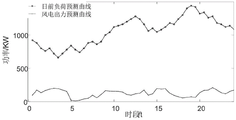
FIG. 4 is a schematic diagram of a day-ahead predicted load curve and a schematic diagram of a wind-solar predicted output curve in a specific application embodiment.
FIG. 5 is a schematic diagram of the day-ahead coordinated scheduling of the system when the total cost of operation of the system is minimized when the waste incineration plant does not participate in peak shaving in a specific application embodiment.
FIG. 6 is a schematic diagram of the day-ahead coordinated scheduling of the system when the total cost of system operation is minimized when the waste incineration plant participates in peak shaving in a specific application embodiment.
Fig. 7 is a schematic diagram of the system day-ahead linear coordination scheduling when the total cost of system operation is minimum when the waste incineration power plant participates in peak shaving in a specific application embodiment.
Detailed Description
The invention is further described below with reference to the drawings and the specific preferred embodiments, without thereby limiting the scope of protection of the invention.
As shown in fig. 1, the source load linear coordination optimization method for participating in peak shaving of the waste incineration power plant of the embodiment includes the steps of:
s1, establishing an energy consumption model of a flue gas treatment device: establishing a refined flue gas treatment energy consumption model according to the existing flue gas treatment device energy consumption model;
s2, acquiring a load time sequence of a wireless trend: acquiring a day-ahead load prediction time sequence, linearly regressing the load, and subtracting the linear load time sequence from the load prediction time sequence to obtain a load with a wireless trend;
s3, constructing a source load coordination optimization model: establishing a source load linear coordination optimization model for the waste incineration power plant to participate in peak shaving, wherein the model takes a wind and light output prediction time sequence and a load prediction curve for removing a linear trend as basic data to carry out day-ahead scheduling plan optimization, and the aim of reducing the system operation cost is fulfilled;
s4, optimizing control: the method comprises the steps of taking a waste incineration power plant as a peak regulation resource to participate in source-load coordination optimization, performing optimization control on power generation and flue gas treatment equipment resources of the waste incineration power plant through the linear coordination optimization model, and simultaneously counting linear loads into the output of a traditional unit, so that the system operation cost is reduced, and wind and light are abandoned.
When the waste incineration power plant participates in peak shaving, the system is equivalently added with adjustable load and power supply, and the adjustable load is mainly treated by adjusting the flue gas. The system load and the new energy output present obvious peak-valley characteristics, so that the output of the unit is adjusted frequently, and the system operation cost is high. The daily burning amount of the waste incineration power plant is basically a fixed value, so the daily total generating capacity is basically fixed, and the generating power can be regulated in different periods. The flue gas treatment power of the waste incineration power plant is large, and after the flue gas storage device is arranged, the flue gas treatment power can be regarded as time-shifting and load power can be adjusted, so that the flue gas treatment time interval is adjusted and controlled, namely, the power load is adjusted. And dispatching and coordinating to adjust the output of the waste incineration power plant, the new energy on-grid output, the response load on the demand side and the output of the traditional thermal power generating unit. A system diagram of a waste incineration plant participating in peak shaving scheduling is shown in fig. 2.
In step S1 of this embodiment, a refined energy consumption model for flue gas treatment is established according to an energy consumption model of an existing flue gas treatment device, that is, an energy consumption function of a gas pump and a unit energy consumption function of flue gas treatment are added in consideration of flue gas inlet and outlet of a gas storage tank.
Air pump energy consumption when the gas holder passes in and out the flue gas:
P S,t =w 1 (α 2,t +α 3,t ),t=1,...,T (1)
in formula (1): w is a 1 Is the specific energy consumption coefficient, alpha, of the air pump 2,t The amount of flue gas, alpha, entering the gas storage tank for the flue gas generated by burning in the time period t 3,t The smoke amount entering the reaction tower from the gas storage tank is a time period T, and T is a period.
Specific energy consumption function of flue gas treatment:
w α,t =w α (1.5-(α 1,t +α 3,t )/θ),t=1,...,T (2)
in formula (2): w is a 1 The unit energy consumption coefficient of the air pump; alpha is alpha 3,t The amount of flue gas entering the reaction tower from the gas storage tank is t; w is a α The energy consumption coefficient of a fixed unit for flue gas treatment; theta is the maximum flue gas treatment capacity per unit time period.
Meanwhile, the energy consumption model of the flue gas treatment device needs to be perfected:
the sum of the amount of smoke entering the air storage tank and the sum of the amount of smoke leaving the air storage tank should be equal:

in formula (3): alpha (alpha) ("alpha") 2,t The amount of flue gas, alpha, entering the gas storage tank for the flue gas generated by the incineration in the time period t 3,t And (4) the smoke gas quantity entering the reaction tower from the gas storage tank for a time period t.
The smoke gas volume of the gas storage tank can not be larger than the maximum gas storage volume:

wherein: eta is the capacity of the air storage tank.
And the flue gas inlet and outlet pipelines have maximum flow limitation:
0≤α 1,t ,α 2,t ,α 3,t ≤δ,t=1,...,T (5)
wherein: delta is the maximum flow rate of the flue gas pipeline.
In step S2 of this embodiment, the specific steps of acquiring the load time series of the wireless tendency are as follows:
obtaining a predicted load time series P L Then, according to the load change trend, the linear regression is carried out in three sections to obtain the slope beta of the load change k ,k=1,2,3。
And finally, acquiring a predicted load time sequence of a wireless trend, and participating in optimization control:

in the formula: p Load,t Time series of loads, P, for wireless trends L,t Prediction of time series, beta, for day-ahead loads t The slope of the time series linear regression is predicted for the load before day.
In step S3 of this embodiment, the established source-load linear coordination optimization model for the refuse incineration power plant participating in peak shaving is based on the wind-solar output prediction time sequence and the load prediction curve without linear trend, and performs scheduling plan optimization in the day ahead to reduce the system operation cost;
f 1 =min(C G (P g,t )+C D (ΔP t )+C W (ΔP w,t )) (7)
wherein f is 1 For the total operating cost of the system, including the operating cost C of the conventional units G (P g,t ) Demand response cost C D (ΔP t ) Wind and light abandoning cost C W (ΔP w,t )。
The target function of the operation cost, the demand response cost and the wind and light abandoning cost of the traditional unit is as follows:

wherein a, b and c represent fuel cost parameters of the traditional unit; d represents a unit output adjustment cost parameter; rho is a unit compensation cost parameter of the demand response load, delta P t For demand response in time t system, i.e. time series P of predicted loads obtained by optimization L,t Subtracting the predicted load; c W Penalty parameter, Δ P, for wind and light rejection w,t The wind-light new energy output P is obtained by optimizing the wind-light abandoning power of the wind abandoning in the time period t w,t And the difference of the predicted new energy output.
In this embodiment, when the source-load linear coordination optimization model is established in step S3, a source-load linear coordination power balance constraint is further set, where the source-load linear coordination power balance constraint includes a load linear regression function, flue gas treatment energy consumption, and power generation in the waste incineration power plant.
As a further improvement of the present invention, the source-to-charge linear coordination power balance constraint is as follows:
P g,t +P W,t +P G,t -P Load,t -β t t-P α,t =0,t=1,...,T (9)
in the formula: p g,t Is the output of the traditional thermal power generating unit, P W,t For new energy contribution, P G,t For waste incineration power plants, P α,t Energy consumption P for flue gas treatment Load,t Time series of loads, beta, being a trend of wireless nature t The slope of the time series linear regression is predicted for the load before day.
In step S4, the method for source load linear coordination optimization of a waste incineration power plant participating in peak shaving includes the following specific steps: and acquiring a date prediction load time sequence and a wind and light prediction output time sequence, performing optimization control on the power generation and flue gas treatment equipment resources of the waste incineration power plant through the linear coordination optimization model, and simultaneously counting linear loads into the output of a traditional unit, thereby reducing the system operation cost and wind and light abandoning.
In this embodiment, when the source-to-load linear coordination optimization model is established, the method further includes the following steps of traditional unit output and climbing constraints, demand response load constraints, waste incineration power plant total output constraints, and the like:
(1) restraint of conventional units
The participation of the traditional unit in scheduling is mainly restricted by output and climbing output fluctuation.
P gmin ≤P g,t ≤P gmax (10)
-P gc ≤P g,t -P g,t-1 ≤P gc (11)
In the formula: p is gmin Is the lower limit value of the output of the traditional thermal power generating unit, P gmax Is the upper limit value of the output of the traditional thermal power generating unit, P gc Is the maximum hill climbing power limit.
(2) Demand response load constraints
The demand side load available for invocation at each time period is limited.
P Dmin ≤ΔP t ≤P Dmax (12)

In the formula: p is Dmax And P Dmin Representing the upper and lower limits of the demand response load, respectively. S pmax And S pmin Respectively representing the upper and lower limits of the total capacity of the demand responsive load during the period T.
(3) And (4) restraining the total output of the waste incineration power plant.

The waste incineration plant has a constant total output, the output of which can be dimensioned per time interval.
To verify the effectiveness of the present invention, the power system shown in fig. 2 is selected as an analysis object, a scheduling cycle is set to be 24 hours, and each scheduling period is set to be 30 minutes. The total installed capacity of the thermal power generating unit is 1500MW, the installed capacity of wind power is 150MW, and the installed capacity of photovoltaic is 50MW. The parameters of the waste incineration plant were as follows: the installed capacity of the waste incineration power plant is 200MW, the daily total generated energy is 4000MW, the maximum output is 200MW, and the smoke emission intensity is e α =0.96, fixed flue gas treatment energy consumption coefficient w α =0.6; specific energy consumption coefficient w of air pump 1 =0.8; maximum flue gas throughput θ =180; the maximum capacity eta of the air storage tank is =600; the initial gas storage amount of the gas storage tank is 200; the maximum flow rate delta =100 of the flue gas pipeline. Let a scheduling cycle be 24h and each scheduling period be 30min. The system load prediction curve and the wind-solar combined contribution prediction curve are shown in FIG. 3. The force limits of the demand side response are shown in table 1. The unit adjustment cost and the wind and light abandoning punishment of the demand response load take 180 yuan/MW & h.
TABLE 1 demand response force limits
| Categories | P Hmin /MW | P Hmax /MW | S pmin /MW | S pmax /MW |
| Responsive load | -80 | 80 | -600 | 600 |
Firstly, comparing the improved flue gas treatment energy consumption model with the traditional flue gas treatment energy consumption model, as can be seen from fig. 4, the energy consumption and the treatment capacity of the traditional flue gas treatment system are in direct proportion, but in the actual process, the treatment efficiency is not constant, so that the energy consumption of the treatment system cannot be accurately described by the original flue gas treatment function, and the overall energy consumption of the flue gas treatment system is actually underestimated. The energy consumption model of the improved flue gas treatment system can reflect the energy consumption trend of the actual treatment system better: when the flue gas treatment capacity is low, the energy consumption of the flue gas treatment system is higher than that of the flue gas treatment system which is not improved, and when the flue gas treatment capacity is higher, the energy consumption is lower, and the energy consumption of the air pump of the flue gas treatment system is taken into consideration by the energy consumption model, and the maximum value of the energy consumption is 80MW, so that the flue gas treatment system can be called more accurately when being used as an adjustable load.
The source load linear coordination optimization model of the waste incineration power plant participating in peak shaving is set with 3 scenes for comparative analysis by taking the total operation cost of the system as the minimum target, and the three scenes are respectively as follows:
scene one: when the waste incineration power plant does not participate in the conventional operation mode of system day-ahead coordinated scheduling when the aim is to minimize the total system operation cost during peak regulation;
scene two: a schematic diagram of system day-ahead coordinated dispatching when the garbage incineration power plant participates in peak shaving and aims at minimizing the total cost of system operation;
scene three: and when the garbage incineration power plant participates in peak shaving, the system day-ahead linear coordination scheduling schematic diagram takes the minimum total system operation cost as a target.
FIG. 5 is a conventional operation of day-ahead coordinated scheduling of the system when the total cost of system operation is minimized when the waste incineration plant is not involved in peak shaving; fig. 6 is a schematic diagram of the day-ahead coordinated scheduling of the system when the garbage incineration power plant participates in peak shaving and the total cost of the system operation is minimum. FIG. 7 is a schematic diagram of the day-ahead linear coordination scheduling of the system when the peak shaving is participated in by the waste incineration power plant and the minimum total cost of the system operation is taken as a target; as can be seen from the three graphs, the output fluctuation of the thermal power generating unit is reduced in the graph 7. And considering that the output of the traditional unit can climb in a certain range in practice, the output of the traditional unit has a linear climbing characteristic. The demand response presents a clear peak clipping and valley filling rule.
The table 2 and the table 3 are respectively the comparison condition of the system operation cost and the new energy consumption condition under different scenes, the fuel cost, the start-stop cost and the total operation cost of the unit are all the largest in a scene-traditional optimized operation mode, and the new energy consumption is the smallest; and a garbage incineration power plant is added in the scene two, the regulation capability is enhanced, some regulation cost can be shared by the traditional unit, the wind and light abandoning is reduced, and the total cost is optimal. And in a third scenario, the output of the traditional unit is stable, the unit adjustment cost is remarkably reduced, the output of the traditional unit follows the daily load change rule, and the demand response cost is reduced, so that the total operation cost of the system is low, and the new energy consumption rate is high.
TABLE 2 comparison of operating costs under three scenarios

TABLE 3 comparison of consumption of new energy under three scenarios
| Scene | Scene one | Scene two | Scene three |
| New energy consumption/%) | 86.5 | 89.8 | 93.4 |
The test results can be obtained, the embodiment utilizes the waste incineration power plant to participate in peak shaving, so that the waste incineration power plant can obtain extra peak shaving income, and the output regulation of the traditional unit is reduced. By providing a source load linear coordination relation of system peak regulation, the output of the traditional unit has the linear characteristic of climbing performance. Based on the method, a source load linear coordination optimization model of the waste incineration power plant participating in system peak shaving is provided. With the increase of the capacity of the waste incineration power plant, the method can participate in electric power auxiliary service and obtain higher benefit by participating in system peak regulation. The flexible operation, the system peak regulation and the regulation of the flue gas treatment load of the waste incineration power plant are also feasible measures for increasing the response capability of a demand side and absorbing new energy.
The foregoing is considered as illustrative of the preferred embodiments of the invention and is not to be construed as limiting the invention in any way. Although the present invention has been described with reference to the preferred embodiments, it is not intended to be limited thereto. Therefore, any simple modification, equivalent change and modification made to the above embodiments according to the technical spirit of the present invention should fall within the protection scope of the technical scheme of the present invention, unless the technical spirit of the present invention departs from the content of the technical scheme of the present invention.
Claims (6)
1. A source load linear coordination optimization method for a waste incineration power plant participating in peak shaving is characterized by comprising the following steps:
s1, establishing an energy consumption model of a flue gas treatment device: establishing a refined flue gas treatment energy consumption model;
increasing a unit energy consumption function considering the energy consumption of the air pump and the flue gas treatment when the gas storage tank enters and exits the flue gas;
air pump energy consumption when the gas holder passes in and out the flue gas:
P S,t =w 1 (α 2,t +α 3,t ),t=1,...,T
in the formula: w is a 1 Is the specific energy consumption coefficient, alpha, of the air pump 2,t The amount of flue gas, alpha, entering the gas storage tank for the flue gas generated by the incineration in the time period t 3,t The amount of flue gas entering the reaction tower from the gas storage tank is T, and T is a period;
specific energy consumption function of flue gas treatment:
w α,t =w α (1.5-(α 1,t +α 3,t )/θ),t=1,...,T
in the above formula: w is a α The energy consumption coefficient of a fixed unit for flue gas treatment; theta is the maximum smoke treatment capacity in unit time interval;
s2, acquiring a load time sequence of a wireless trend: acquiring a load prediction time sequence before the day, linearly regressing the load, and subtracting the linear load time sequence from the load prediction time sequence to obtain a load with a wireless trend;
s3, constructing a source load coordination optimization model: establishing a source load linear coordination optimization model of the waste incineration power plant participating in peak shaving, wherein the model takes a wind-light output prediction time sequence and a load prediction curve for removing linear trend as basic data to carry out day-ahead scheduling plan optimization, and the aim of reducing the system operation cost is fulfilled;
s4, optimizing control: the method comprises the steps of taking a waste incineration power plant as a peak regulation resource to participate in source-load coordination optimization, performing optimization control on power generation and flue gas treatment equipment resources of the waste incineration power plant through the linear coordination optimization model, and simultaneously counting linear loads into the output of a traditional unit, so that the system operation cost is reduced, and wind and light are abandoned.
2. The method of claim 1, wherein the energy consumption model for the refined flue gas treatment established in the step S1 comprises complete constraints;
the model further comprises:
the sum of the amount of smoke entering the air storage tank and the sum of the amount of smoke leaving the air storage tank should be equal:

the amount of flue gas entering the reaction tower;
the smoke gas volume of the gas storage tank can not be larger than the maximum gas storage volume:

wherein: eta is the capacity of the air storage tank;
and the flue gas inlet and outlet pipelines have maximum flow limitation:
0≤α 1,t ,α 2,t ,α 3,t ≤δ,t=1,...,T
wherein delta is the maximum flow of the flue gas pipeline.
3. The method for source-load linear coordination optimization of participation in peak shaving of a waste incineration plant according to claim 2, characterized in that the load time series of the wireless trend obtained in the step S2;
P Load,t =P L,t -β t t
in the formula: p Load,t Time series of loads being trends of wireless nature, P L,t Predicting a time series, beta, for a load before the day t The slope of the time series linear regression is predicted for the load before day.
4. The method of claim 3, wherein the source-to-load linear coordination optimization method for peak shaving participation of the waste incineration power plant,
the source load linear coordination optimization model of the waste incineration power plant participating in peak shaving established in the step S3 takes a wind-light output prediction time sequence and a load prediction curve for removing linear trend as basic data, optimizes a day-ahead scheduling plan, and takes the reduction of the total system operation cost as a target function;
the total system operation cost objective function is determined according to the minimization of the total system operation cost, and the total operation cost is the sum of the operation cost of a traditional unit, the demand response cost and the wind and light abandoning cost;
and the traditional unit operation cost objective function is determined according to the traditional unit total output minimization and the traditional unit output adjustment minimization.
5. The method according to claim 4, wherein the step S4 is performed with optimization control, the power generation and flue gas treatment equipment resources of the waste incineration power plant are optimally controlled through the linear coordination optimization model, and the linear load is counted to the output of the traditional unit, so that the system operation cost and the wind and light abandonment are reduced.
6. The method for source-load linear coordination optimization of participation in peak shaving of a waste incineration power plant according to any one of claims 1 to 5, wherein the specific steps of participation in peak shaving of the waste incineration power plant in the step S4 are as follows: and the system dispatching center optimally controls the output of the waste incineration power plant through the wind-light predicted output and the predicted load and through the flue gas treatment energy consumption function and the source-load linear coordination optimization model, so that the aim of minimizing the total operation cost of the system is fulfilled.
Priority Applications (1)
| Application Number | Priority Date | Filing Date | Title |
|---|---|---|---|
| CN202010637710.0A CN111769552B (en) | 2020-07-02 | 2020-07-02 | Source-load linear coordination optimization method for participating in peak shaving of waste incineration power plant |
Applications Claiming Priority (1)
| Application Number | Priority Date | Filing Date | Title |
|---|---|---|---|
| CN202010637710.0A CN111769552B (en) | 2020-07-02 | 2020-07-02 | Source-load linear coordination optimization method for participating in peak shaving of waste incineration power plant |
Publications (2)
| Publication Number | Publication Date |
|---|---|
| CN111769552A CN111769552A (en) | 2020-10-13 |
| CN111769552B true CN111769552B (en) | 2022-11-11 |
Family
ID=72723736
Family Applications (1)
| Application Number | Title | Priority Date | Filing Date |
|---|---|---|---|
| CN202010637710.0A Active CN111769552B (en) | 2020-07-02 | 2020-07-02 | Source-load linear coordination optimization method for participating in peak shaving of waste incineration power plant |
Country Status (1)
| Country | Link |
|---|---|
| CN (1) | CN111769552B (en) |
Citations (3)
| Publication number | Priority date | Publication date | Assignee | Title |
|---|---|---|---|---|
| CN106655478A (en) * | 2017-01-25 | 2017-05-10 | 云南水务投资股份有限公司 | Low-voltage emergency safety power supply system of household garbage power plant and control method of system |
| CN109888840A (en) * | 2019-02-28 | 2019-06-14 | 内蒙古科技大学 | Scene-garbage power energy comprehensive utilization system method for optimizing scheduling and device |
| CN110163768A (en) * | 2019-05-16 | 2019-08-23 | 长沙理工大学 | A kind of wind-powered electricity generation-waste incineration virtual plant Optimization Scheduling |
Family Cites Families (1)
| Publication number | Priority date | Publication date | Assignee | Title |
|---|---|---|---|---|
| AU2010204729A1 (en) * | 2009-01-14 | 2011-09-01 | Integral Analytics, Inc. | Optimization of microgrid energy use and distribution |
-
2020
- 2020-07-02 CN CN202010637710.0A patent/CN111769552B/en active Active
Patent Citations (3)
| Publication number | Priority date | Publication date | Assignee | Title |
|---|---|---|---|---|
| CN106655478A (en) * | 2017-01-25 | 2017-05-10 | 云南水务投资股份有限公司 | Low-voltage emergency safety power supply system of household garbage power plant and control method of system |
| CN109888840A (en) * | 2019-02-28 | 2019-06-14 | 内蒙古科技大学 | Scene-garbage power energy comprehensive utilization system method for optimizing scheduling and device |
| CN110163768A (en) * | 2019-05-16 | 2019-08-23 | 长沙理工大学 | A kind of wind-powered electricity generation-waste incineration virtual plant Optimization Scheduling |
Non-Patent Citations (1)
| Title |
|---|
| 含烟气储存装置的风电–垃圾焚烧虚拟电厂双阶段优化调度;周任军 等;《中国电力》;20190228;第52卷(第2期);全文 * |
Also Published As
| Publication number | Publication date |
|---|---|
| CN111769552A (en) | 2020-10-13 |
Similar Documents
| Publication | Publication Date | Title |
|---|---|---|
| CN107482688B (en) | Scheduling optimization method for carbon capture virtual power plant | |
| CN108964128B (en) | Low-carbon economic dispatching solving method based on coordinated heat supply of electric boiler and heat storage device | |
| CN111950808B (en) | Comprehensive energy system random robust optimization operation method based on comprehensive demand response | |
| CN105260941A (en) | Techno-economic evaluation method for supply side involving in new energy peak regulation | |
| CN111799772B (en) | Electric heating system optimal scheduling method considering depth peak shaving of unit | |
| CN115689233A (en) | Wind, light, water, fire and storage system complementary coordination optimization scheduling method considering peak regulation initiative | |
| CN114462902B (en) | Distributed power generation dispatching method considering photo-thermal and water potential integrated energy storage output | |
| CN110957722B (en) | Day-ahead optimal scheduling method for micro energy network with electricity-to-gas equipment | |
| CN114548584A (en) | Optimization method of comprehensive energy system containing electric conversion gas and carbon capture equipment | |
| CN117350419A (en) | Park comprehensive energy system optimization operation method considering flexible load and carbon flow | |
| CN114240256A (en) | Electric heating gas comprehensive energy system and collaborative optimization operation control method | |
| CN111769552B (en) | Source-load linear coordination optimization method for participating in peak shaving of waste incineration power plant | |
| CN110378523B (en) | Capacity allocation method for thermoelectric and wind power combined participation power grid peak shaving | |
| CN116739238A (en) | Low-carbon economic dispatching method for comprehensive energy system | |
| CN115860788A (en) | Day-ahead random optimization method and system for comprehensive energy system containing flexible electric heating load | |
| CN116187648A (en) | Virtual power plant thermoelectric combination optimization scheduling method based on thermal decoupling | |
| CN112072679B (en) | Source network load storage coordination optimization method considering flexible active power constraint | |
| CN115936336A (en) | Virtual power plant capacity configuration and regulation operation optimization method | |
| CN112821464B (en) | Renewable energy source and thermal power generation coupling system scheduling model through same grid point | |
| CN115455709A (en) | Low-carbon comprehensive energy system simulation and configuration method considering carbon capture equipment | |
| CN114400652A (en) | Multi-energy power generation optimization scheduling method considering active participation of nuclear power in peak shaving | |
| CN115293495A (en) | Scheduling instruction decomposition method based on dynamic participation factor and energy controller | |
| CN107528352A (en) | A kind of power distribution network active optimization method based on regenerative resource high permeability | |
| CN116826867B (en) | Optimized scheduling and cost compensation allocation method for improving source load multielement peak regulation initiative | |
| CN114362152B (en) | Multi-time scale scheduling method for comprehensive energy system |
Legal Events
| Date | Code | Title | Description |
|---|---|---|---|
| PB01 | Publication | ||
| PB01 | Publication | ||
| SE01 | Entry into force of request for substantive examination | ||
| SE01 | Entry into force of request for substantive examination | ||
| GR01 | Patent grant | ||
| GR01 | Patent grant |