CN1116754C - Digital radio frequency interference canceller - Google Patents
Digital radio frequency interference canceller Download PDFInfo
- Publication number
- CN1116754C CN1116754C CN97195510A CN97195510A CN1116754C CN 1116754 C CN1116754 C CN 1116754C CN 97195510 A CN97195510 A CN 97195510A CN 97195510 A CN97195510 A CN 97195510A CN 1116754 C CN1116754 C CN 1116754C
- Authority
- CN
- China
- Prior art keywords
- subchannel
- frequency band
- signal
- limited frequency
- pseudo
- Prior art date
- Legal status (The legal status is an assumption and is not a legal conclusion. Google has not performed a legal analysis and makes no representation as to the accuracy of the status listed.)
- Expired - Fee Related
Links
Images


Classifications
-
- H—ELECTRICITY
- H04—ELECTRIC COMMUNICATION TECHNIQUE
- H04L—TRANSMISSION OF DIGITAL INFORMATION, e.g. TELEGRAPHIC COMMUNICATION
- H04L27/00—Modulated-carrier systems
- H04L27/26—Systems using multi-frequency codes
- H04L27/2601—Multicarrier modulation systems
- H04L27/2602—Signal structure
-
- H—ELECTRICITY
- H04—ELECTRIC COMMUNICATION TECHNIQUE
- H04L—TRANSMISSION OF DIGITAL INFORMATION, e.g. TELEGRAPHIC COMMUNICATION
- H04L27/00—Modulated-carrier systems
- H04L27/26—Systems using multi-frequency codes
- H04L27/2601—Multicarrier modulation systems
- H04L27/2647—Arrangements specific to the receiver only
-
- H—ELECTRICITY
- H04—ELECTRIC COMMUNICATION TECHNIQUE
- H04L—TRANSMISSION OF DIGITAL INFORMATION, e.g. TELEGRAPHIC COMMUNICATION
- H04L5/00—Arrangements affording multiple use of the transmission path
- H04L5/003—Arrangements for allocating sub-channels of the transmission path
- H04L5/0044—Arrangements for allocating sub-channels of the transmission path allocation of payload
-
- H—ELECTRICITY
- H04—ELECTRIC COMMUNICATION TECHNIQUE
- H04B—TRANSMISSION
- H04B1/00—Details of transmission systems, not covered by a single one of groups H04B3/00 - H04B13/00; Details of transmission systems not characterised by the medium used for transmission
- H04B1/06—Receivers
- H04B1/10—Means associated with receiver for limiting or suppressing noise or interference
- H04B1/1027—Means associated with receiver for limiting or suppressing noise or interference assessing signal quality or detecting noise/interference for the received signal
- H04B1/1036—Means associated with receiver for limiting or suppressing noise or interference assessing signal quality or detecting noise/interference for the received signal with automatic suppression of narrow band noise or interference, e.g. by using tuneable notch filters
-
- H—ELECTRICITY
- H04—ELECTRIC COMMUNICATION TECHNIQUE
- H04B—TRANSMISSION
- H04B1/00—Details of transmission systems, not covered by a single one of groups H04B3/00 - H04B13/00; Details of transmission systems not characterised by the medium used for transmission
- H04B1/06—Receivers
- H04B1/10—Means associated with receiver for limiting or suppressing noise or interference
- H04B1/1027—Means associated with receiver for limiting or suppressing noise or interference assessing signal quality or detecting noise/interference for the received signal
- H04B2001/1063—Means associated with receiver for limiting or suppressing noise or interference assessing signal quality or detecting noise/interference for the received signal using a notch filter
Abstract
In a multi-carrier transmission system, in which interference is likely to occur within a restricted band, no subcarriers are used within that band. In addition, a dummy tone may be used to suppress transmitted power within the restricted band; and a quiet tone may be used to allow the receiver to detect and cancel interference from that band. The dummy tones and quiet tones may be close to the edges of the restricted band, either below, above or both. In particular, these measures are applied to VDSL systems, in which the restricted band corresponds to amateur radio bands.
Description
Invention field
The present invention relates generally to its high speed discrete multitone, DMT data transmission system.Particularly, the dysgenic mechanism that relates to radio frequency (RF) interference that is used for reducing the multi-carrier transmission scheme.
Background of invention
The telecommunications industry scheme solve alliance (Alliance For Telecommunications IndustrySolutions) (ATIS) (it is the tissue by ANSI (ANSI) normal structure mandate) stipulated to be used for going up the Discrete Multitone standard of transmission of digital data recently in ADSL (Asymmetric Digital Subscriber Line) (ADSL).Though it also can be used in other various application, this standard is mainly used in transmitting video data on common telephone line.The North America standard is referred to as ANSI T1.413 ADSL standard, is incorporated herein by reference.The transmission rate of this ADSL standard attempts to promote by the twisted pair telephone line at least with 600,000 bps (that is speed rates information 6+Mbit/s).Standardized system limits the application of Discrete Multitone (DMT) system, and this system adopts bandwidth to be respectively 256 " signal tone " or " subchannel " of 4.3125kHz at forward (descending).Under this situation of telephone system, down direction is defined as from central office's (generally return telephone operator all) to far-end the transmission of (can be the terminal use, i.e. house user or business users).In some other system, the excursion of used signal tone quantity is very big.Yet when using anti-fast Fourier transform (IFFT) when modulating effectively, the representative value of obtainable subchannel (signal tone) quantity is 2 integer power, for example, and 128,256,513,1024 or 2048 subchannels.
It is for the utilization of reverse signal under 16 to 800Kbit/s the data rate that the ADSL (Asymmetric Digital Subscriber Line) standard also defines in scope.Reverse signal is with corresponding in the transmission of up direction (for example from the far-end to the central office).Therefore, term " ADSL (Asymmetric Digital Subscriber Line) " message transmission rate that comes from down direction is higher than the message transmission rate of up direction.This is particularly useful in attempting by telephone line image programs or other vision signal to be sent to the system of far-end.For example, may use for this system a kind of and to make at home the user obtain video information (such as, film), and needn't remove to rent video tape by telephone line or cable.Another kind of potential use is video conference.
When writing this standard, ATIS has begun one's study and has been called as the subscribers feeder transmission system of future generation of VDSL (its high-speed digital subscriber line) standard.The VDSL standard attempts to help down direction with the transmission rate of 12.98Mbit/s at least, and preferably 25.96 or the transmission rate of 51.92Mbit/s.Simultaneously, the digital signal audio frequency and video committee (DAVIC) is studying and is being called as the short-range system that Fiber To The Curb (FTTC).Transmission medium to the user dwelling of these two systems is standard Unshielded Twisted Pair UTP (UTP) telephone wire.
A plurality of multi carrier modulation schemes have been proposed, for the usefulness of VDSL and FTTC standard (VDSL/FTTC hereinafter referred to as).A kind of multicarrier solution of proposition is utilized Discrete Multitone signal (DMT) in itself with in the similar system of ADSL standard.The another kind of modulation scheme that proposes comprises carrierless amplitudephase modulation position (CAP) signal, discrete wavelet multitone modulation (DWMT) and OFDM (it is the reduced form of DMT).In order to obtain the required data rate of VDSL/FTTC, the bandwidth that transmission bandwidth must significantly be wider than ADSL and be considered.For example, the discrete multisound system utilization that ADSL adopts is approximately the transmission bandwidth of 1.1MHz, and the bandwidth that the VDSL/FTTC application is considered is approximately 10MHz.A kind of DMT system that application is proposed for VDSL/FTTC considers that dedicated bandwidth is respectively 256 " signal tone " or " subchannel " of 43.125kHz.
Application for these broad band multicarrier modulator approaches exists some intrinsic obstacles that must overcome.Known as those skilled in the art that, the radio amateur utilizes the frequency band of the several relative narrower in 1MHz arrives the 12MHz scope.For example, keeping following approximate frequency band uses for the radio amateur: 1.8 to 2.0MHz; 3.5 to 4.0MHz; 7.0 to 7.3MHz and 10.1 to 10.15MHz.So Any user line modulation scheme is not exported a large amount of interference in above-mentioned frequency band be crucial, and certainly, this system must arrange to handle the interference of the special high level of this frequency range.The invention provides the mechanism that is used to handle the problems referred to above.
Summary of the invention
The present invention relates to be used for reducing the method and the mechanism of the influence of multi-carrier data transmission systems radio frequency interference.In one aspect of the invention, be suppressed at the interior emission of limited frequency band with the false signal sound.Aspect another, detect the signal that on the quiet signal tone of appointment, receives in the present invention, and it is used to eliminate adjacent now disturbs with the RF on the signal tone.
In a first aspect of the present invention, it relates to the RF emission that is controlled in the limited frequency band, emission false signal sound on selected pseudo-subchannel.Select the amplitude and the phase place of false signal sound to send caused transmitting power in limited frequency band with the secondary lobe that suppresses comfortable limited out-of-band at least one subchannel data of origin.
In certain embodiments, on the different pseudo-subchannel on the opposite side of limited frequency band, send a pair of false signal sound.The physical location of pseudo-subchannel can change according to the needs of particular system.For example, pseudo-subchannel can be the subchannel adjacent with limited frequency band.In another example, pseudo-subchannel can be to make two false signal phonemes in the subchannel away from limited frequency, and adjacent sub-channel is the quiet signal tone of appointment simultaneously.In having the transmission system of a plurality of limited frequency bands, the pseudo-subchannel that separates can be relevant with each limited frequency band.
In a second aspect of the present invention, it relates to the RF that processing receives by modulator-demodulator disturbs, and near at least one subchannel there is the frequency that RF disturbs in expection is the quiet signal tone that can not send the appointment of any signal.Yet, detect the noise that on quiet subchannel, receives, and be used for estimating effectively to appear at selected adjacent now the interference with the RF on the signal tone.So, eliminate to be applied to adjacent existing disturb with the RF on the data-signal that receives on the signal tone with detected noise.
In certain embodiments, provide a pair of quiet signal tone, respectively a quiet signal tone on every side of the limited frequency band of appointment.In certain embodiments, the quiet signal tone of appointment is in the subchannel adjacent with the limited frequency band of appointment.In other embodiments, the quiet signal tone of one or two appointment is in limited frequency band.
In the system that considers the entrance and exit that RF disturbs, false signal sound and quiet signal tone can be used in combination.In these systems, generally with the false signal phoneme outside quiet signal tone.Described structure is effective especially in discrete many signal tones transmission system.
Description of drawings
In conjunction with the accompanying drawings,, can understand objects and advantages of the present invention best with reference to following explanation, wherein:
Fig. 1 is the block diagram that the subscribers feeder communication system with many twisted pair telephone lines that extend to each far-end unit from the optical communication network unit is shown;
Fig. 2 illustrates the power spectrum density figure that changes with 0 transmission frequency in the 12MHz frequency range from the amplitude of the permission through-put power of remote subscriber by the twisted pair open-wire line;
Fig. 3 (a) and 3 (b) are illustrated in the diagram of the voltage amplitude of a type signal sound in typical discrete many signal tones transmission system with frequency change;
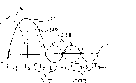
Fig. 4 illustrates the voltage amplitude of a pair of adjacent signals sound with same magnitude and by the figure of voltage bias between the caused signal tone of interference of their secondary lobes separately;
Fig. 5 is the diagrammatic block diagram that the method for setting up simulate signal is shown;
Fig. 6 is the curve that received power changed with transmission frequency in the far-end unit peak signal sound during the typical case of explanation VDSL on the twisted pair transmission line used;
Fig. 7 illustrates and further considers the consequence that signal tone brought of turn-offing in the limited frequency band, the amplitude of received power in the far-end unit peak signal sound shown in Figure 6;
Fig. 8 is according to a structure of the present invention, at 1.8 schematic diagrames near the signal tone the limited frequency band of 2.0MHz;
Fig. 9 is according to second structure of the present invention, at 1.8 schematic diagrames near the signal tone the limited frequency band of 2.0MHz;
Figure 10 is according to the 3rd structure of the present invention, at 1.8 schematic diagrames near the signal tone the limited frequency band of 2.0MHz;
Figure 11 is according to the 4th structure of the present invention, at 1.8 schematic diagrames near the signal tone the limited frequency band of 2.0MHz;
Figure 12 is according to one embodiment of present invention, realizes the block diagram of the central modulator-demodulator of discrete many signal tones transmission plan;
Figure 13 is according to one embodiment of present invention, realizes the block diagram of the far-end modulator-demodulator of discrete many signal tones transmission plan.
Detailed description for accompanying drawing
With reference to Fig. 1, will the relevant portion of the typical wireline telecommunication network that is fit to application VDSL/FTTC be described briefly.This system comprises the central office 10 that a plurality of distribution stations 11 is provided service, and distribution station shown in it may adopt the form of optical communication network unit (ONU).Each distribution station communicates with central office 10 by one or more high speed multiple connection transmission line 12, and the high-speed transmission line of multiple connection shown in it 12 can adopt the form of fibre circuit.Optical communication network unit 11 generally provides service to many discrete subscribers feeders 15.Every subscribers feeder 15 generally provides service to being positioned at apart from a terminal use of ONU 1.5 kilometer range.The terminal use can have and is fit to the far-end unit 18 that communicates with very high data speeds and ONU.Far-end unit comprises modulator-demodulator, but can adopt various device, for example, and phone, TV, monitor, computer, conference device etc.Certainly, the user can have and links multi-section phone or other far-end unit 18 on the circuit.Provide the subscribers feeder 15 of service generally ONU to be installed in the shielded tension disk by an ONU11.It generally is for emission (outlet) and reception (inlet) for the RF noise good insulation performance body to be arranged that tension disk has shielding.Yet the final stage of this subscribers feeder (being commonly referred to as " downlead ") begins bifurcated through tension disk, and the direct or non-far-end unit that directly is coupled to the terminal use.These " downlead " 23 parts of subscribers feeder 15 between far-end unit 18 and tension disk 21 are not shielding generally.In majority was used, the length of downlead was not more than 30 meters.Yet non-shielding conductor works to transmit and receive the antenna of RF signal effectively.In addition, also consider the connection 25 between ONU11 and twisted pair subscribers feeder 15, also can be used as the receiver of RF energy emission source and RF energy.
Can send the energy of particular communications system emission by government and practical studies management.As mentioned above, in the discrete many signal tones system that is fit to that VDSL/FTTC uses, just considering to be approximately the frequency band of 12MHz.In this 12MHz frequency range, there are several narrow-bands of distributing to the ham radio user.So Fig. 2 illustrates the transmitted power spectral density for a plan usefulness of VDSL/FTTC uplink communication.In this embodiment, transmit power mask all allows to be to the maximum-60dBm/Hz at most of frequency band.Yet, (wherein, exist the ham radio RF of expection to disturb (that is, 1.8 to 2.0MHz, and 3.5 to 4.0MHz, and 7.0 to 7.3MHz and 10.1 to 10.15MHz), wherein send the very low degree that is limited in the selected frequency band.Allowed output power levels in these limited frequency bands, some difference between the various proposals.Yet most of participants of VDSL/FTTC standardization effort have been proposed in and have been approximately-maximum power density of 80dBm/Hz in the scope of-90dBm/Hz.Concrete proposals are-86dBm/Hz that it can provide the system that is enough to stop to wireless a large amount of interference of 50 feet that are positioned at emission source (generally being that downlead 23 or ONU/ subscribers feeder connect 25).Regardless of the actual transmission power of reaching an agreement at last, should make great efforts to make the emission minimum in forbidden range.
The multicarrier delivery plan (such as, DMT) in, physical presence drops on some subchannels (signal tone) in the limited frequency range.Therefore, the first step that reduces to launch in limited frequency range is to turn-off those particular sub-channel.This has brought following advantage, that is, reduce the emission in forbidden frequency range and reduce to enter (reception) adverse effect by radio signal.Yet, the personnel that are familiar with this technical field as can be known, at the selected frequency center (f of institute
c) on every side signal specific sound, be difficult to collecting post's emitted power amount.Then, with reference to Fig. 3 (a), the emission relevant with the signal specific sound generally comprises at frequency center (f
c) some secondary lobes of constantly subtracting of higher relatively power emission on every side and the intensity of on its either side, extending.Fig. 3 (b) illustrates the absolute value of the intensity of the signal specific sound with 43.125kHz bandwidth and secondary lobe.Also define the position of secondary lobe power peak.First side lobe peak is the mid point about between close first and second signal tones of central signal sound greatly, and its peak power is (2/3 π) at the power magnitude at centre frequency place
2Doubly (that is, being approximately 4.5%).Second side lobe peak is approximately the mid point between central signal sound the second and the 3rd signal tone nearby, and its peak power is (2/5 π) at the power magnitude at centre frequency place
2Doubly (that is, about 1.6%).The 3rd side lobe peak is the mid point between central signal sound third and fourth signal tone nearby greatly, and its peak power is (2/7 π) at the power magnitude at centre frequency place
2Doubly (that is, being approximately 0.8%), the rest may be inferred.
The amplitude of secondary lobe power and phase place make by turn-off simply signal tone in the limited frequency band come power spectrum density be limited in DMT send in the frequency band than very difficult in the close limit.For example, consider that the utilization bandwidth is the system of the signal tone of 43.125kHz.If attempt by turn-off simply in the wide forbidden range of 200kHz signal tone (promptly, in that to send bandwidth be signal tone 42 to 46 in 0 to 11.04MHz the system), form the wide recess of 200kHz 1.8 in the 2.0MHz scope, then the transmitting power of the center of forbidden range will only be reduced to approximately-73dBm/Hz from 60dBm/Hz.Obviously, this caused emission far above-80 or-the required scope of 90dBm/Hz, even in the center of forbidden frequencies scope.Certainly, the transmitting power of the frequency at the edge of close forbidden frequencies scope can significantly improve.So, if attempt only to pass through to turn-off some signal tones in multicarrier transmission systems, reducing emission, the signal tone quantity that needs so to turn-off will be much higher than the signal tone quantity relevant with the forbidden frequencies scope.For example, in aforesaid many signal tones system that disperses, must turn-off all subchannels that arrive in the 2.2MHz scope 1.6 probably, launch with required the reducing that obtains in 1.8 to 2.0MHz forbidden frequency range.Big frequency band is unwelcome to avoid interference ham radio though discrete many signal tones system in that choose can be very flexible aspect user's frequency, requires to turn-off so, and can reduce systematic function.
With reference to Fig. 4, " interference " effect of the contiguous secondary lobe of signal tone will be described in.As shown in the figure, signal tone (T
n) there is given voltage level at the centre frequency place of relevant subchannel.At the adjacent signals sound (that is, at signal tone (T
N-1) and (T
N+1)) locate T
nThe voltage of signal 147 reduces to zero.For convenience of description, Fig. 4 only is illustrated in the secondary lobe of signal tone (n) side.However, it should be understood that described relation is symmetrical.The voltage of first secondary lobe, its peak value between the first and second adjacent signals sounds (that is, at signal tone (T
N+1) and (T
N+2) between) and mid point.Crest voltage is signal tone (T
n) voltage (2/3 π) doubly.At signal tone (T
N+2), (T
N+3) waiting the place, secondary lobe voltage is once more by zero, and the mid point between the two reaches middle peak value.The amplitude of second side lobe peak is signal tone (T
n) voltage (2/5 π) doubly.The amplitude of the 3rd secondary lobe voltage peak is signal tone (T
n) voltage (2/7 π) doubly.
If we consider signal tone (T
N-1) have and signal tone (T
n) identical amplitude and phase place situation, signal tone (T so
N-1) 148 secondary lobe reflected (T in fact
n) 147 secondary lobe, unique not being both turned left and moved a signal tone (as shown in Figure 4).T under arbitrary characteristic frequency
nAnd T
N-1The combination voltage of signal is their summations of voltage separately.An important observation is under the frequency of arbitrary adjacent signals sound, T
nAnd T
N-1The voltage of signal 147,148 is zero.In addition, the actual out-phase of secondary lobe.That is, under same frequency, signal tone T
nSecondary lobe voltage reach its positive maximum, synchronous signal sound T
N-1Secondary lobe voltage reach its negative maximum, vice versa.So secondary lobe is tending towards setovering mutually to small part, shown in the line 149 of Fig. 4, this line illustrates T
nAnd T
N-1The linear summation of voltage of signals.In the example that provides, suppose signal tone T
nAnd T
N-1Amplitude identical with phase place.Certainly, if the amplitude difference of signal tone, the amplitude of secondary lobe voltage also changes so.
When considering the effect of additional signal sound, under arbitrary given frequency, the combined effect of a plurality of signal tones is their effective summations of voltage separately under institute's selected frequency.So, if we want to control the amplitude and the phase place of the power that is produced by each secondary lobe under characteristic frequency, so can be by selecting appropriate voltage to finish it to one or more signal tones.In one aspect of the invention, be suppressed at transmitting power in the limited frequency band with one or more false signal sounds.
In order to understand the favourable part of utilization false signal sound, consider said system, it has the limited frequency band (that is signal tone 42-46) in its range of transmission.Frequency (the f that consideration is being concerned about
x) the effect of a plurality of adjacent low frequency signal sound secondary lobes in specific M signal voice frequency place, this M signal voice frequency place is the lowest signal sound (T in the limited frequency band
n) and signal tone T
N+1Between mid point (that is, between signal tone 42 and 43).Because the low frequency signal sound makes and works as them at frequency (f
xWhen occurring '), by the low frequency signal sound at frequency (f
xIt is that the low frequency signal sound is at frequency (f that the secondary lobe of ') locating disturbs
xThe summation of its secondary lobe when ') locating to occur.Rank of effect to them are estimated to be approximately:
Interference=β
1T
N-1+ β
2T
N-2+ β
3T
N-3+ β
4T
N-4+ β
5T
N-5+ β
6T
N-6(1)
Wherein, β
1Be to be illustrated in frequency f
xFollowing signal tone T
N-1Secondary lobe voltage and signal tone T
N-1The suitable multiplier of the relation of the voltage of itself; β
2Be to be illustrated in frequency f
xFollowing signal tone T
N-2Secondary lobe voltage and signal tone T
N-2The suitable multiplier of the relation of the voltage of itself, or the like.So, by using signal tone T
N-1The false signal sound, can eliminate frequency f effectively
xThe side lobe effect of the low frequency signal sound at place, wherein said false signal sound has frequency f
xThe secondary lobe amplitude at place, it is equal to the negative of the weighted sum of previous each signal tone.That is, if:
β
1T
n-1=β
2T
n-2+β
3T
n-3+β
4T
n-4+β
5T
n-5+β
6T
n-6+β
7T
n-7……(2)
T
n-1=α
2T
n-2+α
3T
n-3+α
4T
n-4+α
5T
n-5+α
6T
n-6+α
7T
n-7……(3)
Wherein, α
2=β
2/ β
1α
3=β
3/ β
1α
4=β
4/ β
1, or the like, secondary lobe is in frequency f so
xThe array output voltage at place is zero.So, clearly, the false signal sound can be used for reducing in a large number the amplitude of the effect that secondary lobe disturbs.By above-mentioned factor is used for the secondary lobe relevant with the main signal sound (that is, and-2/3 π ,+2/5 π ,-2/7 π, or the like), for the α multiplier, this must descend train value:
α
2=3/5=-0.60
α
3=3/7=0.43
α
4=3/9=-0.33
α
5=3/11=0.27
α
6=3/13=-0.23
α
7=3/15=0.20
α
8=3/17=-0.18
α
9=3/19=0.16
α
10=3/21=-0.14
α
11=3/23=0.13
As the method for practicality, owing to can ignore the amplitude of false signal sound and the influence of phase place away from its effect of signal tone of limited frequency range, so generally do not need to all previous signal tone weighted sums.Yet as mentioned above, secondary lobe is tending towards in the both sides of the centre frequency of signal tone symmetry.Therefore, consider that the signal tone effect on the both sides that appear at interested frequency is crucial.For example, preferably, on every side, use in the scope of about 5 to 20 signal tones, perhaps more preferably, on every side, use in the scope of about 10 to 15 signal tones.In a particular embodiment, use 10 signal tones the most adjacent on every side of limited frequency band.
Though described embodiment disturbs emission very effective for the RF that reduces in limited frequency band, also should be taken into account several other factorses in the computational process of multiplier.At first, eliminate fully in limited frequency band between first and second signal tones (that is, at signal tone T
nAnd T
N+1Between) the locational secondary lobe interference power of the midpoint secondary lobe that will can not cause eliminating fully in the whole limited frequency band disturb.This is because secondary lobe can not decayed pro rata.So, it is desirable to, select to reduce better the value of whole power of the interference in limited frequency range for the α multiplier.In this computational process, can adopt any technology in the multiple known power minimization technique.For example, a kind of suitable method is to utilize LMS least mean square.Certainly, in the process of calculating suitable α multiplier, it is also conceivable that a plurality of other secondary rank factors.
Then, with reference to Fig. 5, embodiment utilization is positioned at a pair of limited frequency band on the relative both sides of limited frequency band.Each false signal sound is included in 10 signal tones the most adjacent on every side of limited frequency band.So the false signal sound is the weighted sum of each adjacent signals sound.Set up of the input of false signal sound as IFFT modulator 45.
When limited frequency band during, generally need on every side of limited frequency range, provide a false signal sound simultaneously for limited frequency range provides the false signal sound right with respect to the wider width of subchannel.Yet, when the bandwidth of limited frequency band is narrower with respect to the bandwidth of subchannel, (for example, when the wide subchannel of utilization 43.125kHz, under the situation of 10.1 to 10.15MHz frequency ranges, have only one or two subchannel wide), can and need only single false signal sound is used together in conjunction with whole limited frequency band.On the other hand, very wide and required amount of suppression is very high that (for example, if require 40dBm/Hz to suppress in above-mentioned example in) the application, it is very useful and/or necessary that a pair of false signal sound all is provided on every side of limited frequency band at limited frequency band.Though the calculating of α multiplier is complicated more, it should be understood that, can obtain better inhibition.Certainly, in other is used, can also adopt additional false signal sound.
Should be understood that the various amplitude of signal tone and the phase places now used are different with code element.Therefore, along with the time changes, the amplitude of specific false signal sound and phase place will not fixed.Say more truely, all should calculate it for each code element.Yet the value of α multiplier can remain unchanged.According to this structure, transmitter only need calculate the amplitude and the phase place of false signal sound by used simple add circuit etc. before sending each code element.Therefore the design computational constant of coupling system, when using constant multiplier, can not consider the multiplier complexity of calculation.
Find, above-mentioned will be with limited frequency band adjacent or very contiguous false signal sound use in conjunction with turn-offing the signal tone that overlaps limited frequency band simply, and it is very effective to drop on the emission that the RF in the limited RF frequency band in the 1-12MHz frequency band range disturbs for control.In the twisted pair subscribers feeder is used, believe that unshielded downlead most possibly is that RF disturbs emission source.Owing to generally with lead far-end unit 18 is linked on the downlead, 10 the RF that uplink communication proposed disturbs emission problem particular importance from the far-end unit to the central office.
The personnel that are familiar with this technical field as can be known, when the high frequency multi-carrier signal by the twisted pair transmission line reach one section very long apart from the time, they have very big decay.For example, with reference to Fig. 6, when transmitted power in the whole transmission bandwidth of the VDSL of DMT modulation scheme be approximately-during 60dBm/Hz, the received power at general remote subscriber place is approximately-70dBm/Hz at the frequency spectrum low side, is-125dBm/Hz but might reduce to frequency spectrum high-end.Therefore, under the situation of downlead, when downstream signal arrives downlead, decayed to the allowed power spectrum density that is enough to be lower than in limited frequency range 34 away from emission source.So, well shield at the line that connects between ONU and the twisted-pair feeder, and twisted-pair feeder leaves ONU one long distance also well in the application of shielding, can in downstream signal, need not or use the false signal sound less.
In described main embodiment, turn-off the signal tone in limited frequency range simply, thereby on these signal tones, do not send any data.Yet, as shown in Figure 2, in limited frequency band, do not forbid any transmission, or rather, must reduce at the power spectrum density in those frequency bands and be lower than specified threshold value.Therefore, in some applications, can send data on the signal tone in one or more limited frequency bands only by reducing the signal tone power in limited frequency range.Prove that the side lobe noise that suppresses from the outer signal tone of limited frequency band range with the false signal sound is very useful in these are used.In described embodiment, the false signal sound is arranged on outside the limited frequency band.Yet in some limited environment, the actual utilization that drops on the false signal sound in the limited frequency band is very useful for the emission net power that reduces in frequency band.
As mentioned above, the problem of the no less important in the embodiment of broad band multicarrier modulation scheme relates to the processing to introducing the twisted pair transmission line and being disturbed by the RF that modulator-demodulator receives.The ham radio that is entered disturbs the form that often is less than the wide narrow band interference of 4kHz.Yet the position of interference can be dropped on the interior arbitrary position of limited frequency band, and may jump to another frequency band from a frequency band discontinuously.In addition, may receive interference from the two or more particular transmitter that send at the frequency band that separates simultaneously.When antenna being arranged on other unshielded part of close relatively downlead or transmission line, the RF interference intensity that receives can make the signal tone intensity in affected frequency band diminish.The VDSL design specification is considered the very high arrowband RF noise of intensity that is introduced in the limited frequency band.Therefore, consider to provide several mechanisms to reduce the influence that RF disturbs.
As shown in figure 12, earlier transformer 61 is arranged on the A/D converter before to reduce common-mode noise.Because transmission line is a twisted pair,, most of RF is transformer 61 quenchable common-mode noise forms so disturbing.For example, transformer can deduct 30 with the RF noise that receives.Yet, still have the much noise that must suppress to detect dmt signal with permission by the difference mode signal of transformer.For example, the VDSL standard is considered the differential mode noise intensity up to-10dBm/Hz.By other noise reducing mechanism (eliminating unit etc. such as differential mode), the output of transformer 61 is directly inputted to A/D converter or the non-A/D of being directly inputted to converter.It is the filter that is used to suppress from the difference mode signal of transformer output that differential mode is eliminated the unit, and wherein said difference mode signal is because uneven caused between the RF noise that receives on two leads that constitute twisted pair.For example, in provisional application sequence number the 60/016th, No. 251 (applying on April 19th, 1996 that by people such as Cioffi name is called: " radio frequency noise canceller "), suitable differential mode elimination unit is described.This application is incorporated herein by reference.
The signal that is received by A/D converter 62 will comprise the remarkable RF noise component(s) that must be handled by receiver, and with to carry out filtering before the A/D converter irrelevant.As mentioned above, turn-offed the signal tone in the limited frequency band, disturbed to stop transmitting RF.Therefore, there are not any data on the arbitrary subchannel in limited frequency band.So a kind of method that reduces the arrowband RF noise component(s) in receiver provides the notch filter in limited frequency band.Notch filter can be sef-adapting filter or static filter and can carry out work to the analog or digital signal.Owing to sef-adapting filter can be transferred to the frequency that input RF disturbs, so sef-adapting filter has the advantage of carrying out better noise suppressed.Yet as the personnel that are familiar with this technical field as can be known, the frequency of determining skyborne unknown RF signal is a relative difficult, therefore needs a large amount of relatively Digital Signal Processing that the filter of the latent defect of cost and system responsiveness aspect is arranged with realization.In addition, when RF interference in arrowband is positioned on the marginal position that is close to limited frequency band relatively, because its cutting overlaps the secondary lobe on the trap frequency range, so may make the adjacent signals sound produce bigger distortion.
On the contrary, static filter has advantage cheaply, but owing to they can not be transferred to the frequency that RF disturbs, so they must be transferred to the characteristic frequency (for example, the center of limited frequency band) in limited frequency band.For example, the static filter that can be used in the particular restricted frequency band is in the centre of limited frequency band.Though static filter is carried out good noise filtering at its tuned frequency, during the humorous frequency of institute's tuningout of the frequency departure filter that disturbs as RF, its performance will reduce greatly.So another aspect of the present invention provides and is used for further reducing the another kind of mechanism that RF disturbs.This mechanism is actually the usage that reverses above-mentioned false signal sound with respect to the RF interference issue.
More particularly, if near the subchannel that is positioned at the limited frequency range, do not send any signal tone, (that is, subcarrier (n-1) is " quiet " signal tone), so because the character of multi-carrier transmission, make that secondary lobe by the side frequency signal tone causes at signal tone T
N-1Frequency under anticipated signal intensity be zero.This point of best illustration in Fig. 2.So, at quiet signal tone T
N-1Going up detected any signal strength signal intensity supposition is to disturb (RFIT by RF
N-1) the causing of effect.In case determine the consequence of radio frequency interference for quiet signal tone, can attempt to estimate the expected interference of adjacent signals sound so.Should be understood that the actual frequency that disturbs as RF is under the condition of unknown, calculate for adjacent will be coarse technology now with the expected interference of signal tone.Yet, by doing some simple hypothesis, can calculate the λ multiplier similar with the α multiplier, this will provide the preferable relatively estimation to the expected interference of adjacent signals sound.
The worst condition that disturbs is that RF disturbs interior margin signal sound of limited frequency and the situation on the point midway between the adjacent signals sound of being located at.Suppose worst condition skew (that is, the RF noise is located on the point midway between first and second signal tones in the limited frequency range), the amplitude of then above-mentioned secondary lobe with respect to the main signal sound and the quantity of phase place are (promptly,-2/3 π ,+2/5 π ,-2/7 π or the like) also can be used for RF and disturb.So, determine that with simple " worst condition " method value that the λ multiplier will cause being used for the λ multiplier is identical with the value that is used to calculate first group of α multiplier.That is:
λ
2=3/5=-0.60
λ
3=3/7=0.43
λ
4=3/9=-0.33
λ
5=3/11=0.27
λ
6=3/13=-0.23
λ
7=3/15=0.20
λ
8=3/17=-0.18
λ
9=3/19=0.16
λ
10=3/21=-0.14
λ
11=3/23=0.13, or the like.
The λ multiplier is to work as and measured quiet signal tone (RFIT
N-1) RF disturb when multiplying each other, will be provided at the factor of the estimation that the RF that observes on the coherent signal sound disturbs.It should be noted that when the frequency of disturbing when the RF secondary lobe reaches the specification signal sound that the RF secondary lobe disturbs and will begin decay relatively quickly.Really, concentrate on the signal tone place if RF disturbs, this effect reduces to zero (with reference to Fig. 3 (a) and 3 (b) as seen) so in theory.In addition, RF disturbs the center of approaching limited frequency band more, and notch filter will more preferably reduce interference intensity.In addition, when the signal tone away from the relevant edge of limited frequency band comprises RF and disturbs, disturb and affectedly now will increase with the interval between the signal tone at RF, it also causes reducing interference intensity.So as above-mentioned the proof, when signal tone that will be adjacent with limited frequency range during as quiet signal tone, the basis that is used as calculating the λ multiplier with worst case scenario is normally a kind of approximate relatively preferably.Yet multiplier is described considers various other factors like that to calculating as mentioned, can make the calculating optimization to the λ multiplier.Generally, be tending towards on statistics, eliminating to greatest extent at existing RF noise with the signal tone place.In addition, least square fitting method is fit to be used for calculating the λ multiplier.
In the above-described embodiments, the quiet signal tone that records is located on the opposite side of the limited frequency band adjacent with limited frequency band.Yet this not necessarily.In another embodiment, in fact one or two quiet signal tone that records may be the signal tone in limited frequency band.Optimal signal tone in limited frequency band is the signal tone in each edge of limited frequency band.In yet another embodiment, estimate with detector whether the RF noise of importing drops on the lower end or the upper end of limited frequency band.Record quiet signal tone with the signal tone adjacent as first, will record quiet signal tone as second at the margin signal sound in the limited frequency band simultaneously with RF being disturbed limited frequency band side of living in.
Only needing only need to provide the quiet signal tone that records in the application of control inlet.Fig. 8 illustrates an embodiment who utilizes a pair of quiet signal tone that records on the opposite side that is positioned at limited frequency band.In this embodiment, limited frequency band 201 is 1.8 to 2.0MHz, and overlaps on the signal tone 42-46 in the DMT system with the wide subchannel of 43.125kHz.The quiet signal tone that records comprises signal tone 41 and 47.In an illustrated embodiment, need two additional sub-channel (for example, signal tone 41 and 47).As mentioned above, replace measuring quiet signal tone 41 and 47, can measure one or two signal tone 42 and 46 (they have all dropped in the limited frequency band range) rather than signal tone 41 and 47.If can obtain satisfactory performance, so because this method has reduced the expense relevant with avoiding limited frequency band (this will improve performance), so this method generally is preferable by one or two quiet signal tone that records of measuring in limited frequency band.
On the contrary, only needing only need to provide the false signal sound in the application of control outlet.Fig. 9 illustrates an embodiment similar with Fig. 8, and it utilizes a pair of false signal sound on the opposite side of limited frequency band.So, the false signal sound is included in subchannel 41 and 47.As mentioned above, in having some embodiment of very narrow limited frequency band, can utilize single false signal sound to obtain required performance.
In other embodiments, may need to finish control to entrance and exit by the combination that utilizes false signal sound and the quiet signal tone that records.For example, Figure 10 illustrates and Fig. 8 and 9 similar embodiment, the quiet signal tone that it utilizes the false signal sound and records.In this embodiment, signal tone 40 is that low false signal sound, signal tone 41 are that low quiet signal tone, signal tone 47 are that high quiet signal tone and signal tone 48 are high false signal sounds.It should be noted that preferably the outside with the quiet signal tone that records of false signal sound setting.The quiet signal tone that records is arranged between limited frequency band and the false signal sound and can provides buffering area on every side at limited frequency band, and it helps to be suppressed at the side lobe effect in the limited frequency range.In addition, if when calculating the value of α multiplier, the quiet signal tone 41 and 47 that consideration records is so owing to being not limited in the amplitude and the phase place of the gross power in signal tone 41 and 47, so can make this value optimization further to reduce the power of in limited frequency band (signal tone 42-46).
In another embodiment shown in Figure 11, a pair of false signal sound is set in subchannel 40 and 47, in subchannel 41 and 46, be provided with the quiet signal tone that records simultaneously.That is, a quiet signal tone that records drops in the limited frequency band.As an alternative, the false signal sound can be arranged on subchannel 41 and 48, simultaneously signal tone 47 be used as the quiet signal tone that records.In the time can obtaining satisfactory performance by this method, it is preferable comparing it with the embodiment of Figure 10, and that is that its only needs three additional sub-channel of utilization because compare with required four additional sub-channel of the embodiment of Figure 10.The useful in certain embodiments another kind of best approach is arranged on the false signal sound near on the limited frequency band position of (as shown in Figure 9), and outmost signal tone that will be in limited frequency band is as recording quiet signal tone.In other embodiment, can provide additional false signal sound and/or additional quiet signal tone, to obtain desired properties.In these embodiments, generally the false signal sound is positioned at the outside of any quiet signal tone, although be not strict the needs like this.
Then, will the central modem structure that be fit to realize described discrete many signal tones transmission plan be described with reference to Figure 12.One or more fiber optic backbone is being coupled among the many embodiment on the twisted pair final exchange line the central modulator-demodulator 30 general forms that adopt ONU.Central authorities' modulator-demodulator comprises optical fiber interface 41, transmitter 40, receiver 70 and controller 60.Controller 60 is used for making the clock of far-end modulator-demodulator and clock synchronization at central modulator-demodulator, and makes the frame that sends from the far-end modulator-demodulator synchronous mutually.Central office 10 provides numerical data by asynchronous transmission modulator-demodulator switch 41 (being denoted as optical fiber interface in the drawings) to transmitter 40.Because the type of performance, transmission range, quality transmission lines and the used communication line of transmitter, central office 10 can be to provide data up to the maximum data rate that allows.Transmitter 40 is introduced the several assemblies that comprise encoder 43, discrete many signal tones modulator 45 and window filter 46.Encoder 43 is used for the data that will transmit (such as, video data) are carried out multiple connection, synchronously and coding.More particularly, for each subchannel in many subchannel, it converts the bit stream of input to homophase and quadrature component.Available forward error correction and/lattice type decoding encodes.Encoder generally is used to export a plurality of sub-symbols sequences, and it equals the quantity of the obtainable subchannel of system.For example, in the system with 256 subchannels, encoder output 256 deducts the sub-symbols sequence of the quantity of the subchannel in limited frequency band.These inputs are to lead to the input of the plural number of discrete many signal tones modulator 45.For example, in the ansi standard file of reference, describe suitable encoder in detail.
Modulator 45 is by arbitrary suitable algorithm, calculates the IFFT modulator of inversefouriertransform.By name at J.Bingham: described suitable IFFT encoder in the paper (IEEECommunication Magazine, May 1990) of " multi-carrier modulation: a kind of design that its epoch have arrived ".Because encoder output is plural number, the IFFT modulator receives the input that is equivalent to the obtainable twice of subchannel.In discrete many signal tones system, suitably determine bit distribution.For the ease of determining that transmitter 40 also comprises line monitor, its monitor communication circuit is to determine the line quality of each obtainable subchannel.In one embodiment, line monitor (it may be the part of controller 60) is determined noise level, gain and phase shift on each subchannel.This purpose is for to each subchannel estimated snr.Therefore, can also monitor other parameter or with the described parameter of other parameter substitutions.According to several factors, determine that dynamically those channels send encoded data and send how many data on each channel.This factor comprises line quality parameter, subchannel gains parameter, the power mask of permission and the required maximum subcarrier bit error rate through monitoring.In fact even can change it should be noted that between subchannel various factors are not necessarily constant, in the utilization process.It should be noted that most detection line mass parameter repeatedly, and when the line quality on each subchannel in the utilization process changes, in real time modulation scheme is adjusted dynamically to regulate modulation.For example, in identical ATIS normative document, summarized suitable discrete many signal tones modulator.
, with after forming discrete many tone signal Cyclic Prefix is attached on discrete many signal tones code signal at the encoded signal of modulated.Cyclic Prefix is mainly used in the demodulation of simplification to discrete many tone signal, and requires not strict.The length of Cyclic Prefix can be made many variations.For example, in 512 sampling circulations, can use 40 Cyclic Prefix.
Then, modulated signal is by window filter 46 and/or other filter, so that the output minimum of frequency band energy.This helps to prevent that the analog interface in the remote receiver is saturated.Can realize this window by the great amount of conventional window protocol.Transmitter also comprises analog interface 48, and its many tone signal that will disperse imposes on transmission medium.In the rigid line system (such as, twisted pair telephone line and coaxial cable), the form that analog interface can adopt circuit to drive.
Central authorities' modulator-demodulator 30 also comprises the receiver 70 that is used to receive from many tone signal of far-end unit.Receiver 70 comprises analog interface 72, window filter 74, demodulator 76 and decoder 78.Receive the signal that receives by central modulator-demodulator 30 by analog filter 72 at first.Window filter 74 is used for carrying out effectively to the received signal window and/or filter function.A kind of suitable filter apparatus is a time-domain equalizer 74.Moreover, can realize window by the window protocol of a plurality of routines.Discrete many tone signal of 76 pairs of equilibriums of demodulator are carried out demodulation, and remove Cyclic Prefix.78 pairs of signals through demodulation of decoder are decoded.Demodulator 76 and decoder 78 are carried out the reverse functions of modulator 45 and encoder 43 respectively effectively.Then, through decoded signal from decoder 78 to central office 10, perhaps by interface 41 other suitable user to information.In No. the 5th, 285,474, people's such as Chow United States Patent (USP), describe the function of time-domain equalizer 74, demodulator 76 and decoder 78 and the algorithm that is fit to realize required function in detail.
Then, be fit to realize synchronous far-end unit structure of the present invention with describing with reference to Figure 13.Though the uplink and downlink message capacity is different, in many aspects, far-end modulator-demodulator and central modulator-demodulator are similar.By transformer 61, notch filter 185 and arrester 63, receive the signal that central modulator-demodulator 30 sends by far-end unit 50.Far-end unit 50 comprises analog interface 172, suitable equalizer (TEQ) 174, discrete many tone signal of equilibrium is carried out demodulation and removed the demodulator 176 and the decoder 178 to decoding through the signal of demodulation of Cyclic Prefix.Time-domain equalizer 174 is carried out filter function effectively to the received signal.Also can adopt window filter.Demodulator 176 and decoder 178 are carried out the reverse functions of modulator 45 and encoder 43 respectively.Then, through the decoding signal from decoder 178 lead to far end device 22 (such as, video telephone, television set, computer or other suitable receiving system).The function of time-domain equalizer 174, demodulator 176 and decoder 178 is similar with the function of the corresponding component in central modulator-demodulator.Analogue notch 185 can be arranged on the upward position of analog filter 172 of receiver, being blocked in the energy in the limited frequency band, thereby help prevent entering of unwanted RF signal.Transformer 61 can be set suppressing common-mode noise, and/or can be provided with and eliminate unit 63 to suppress by the uneven caused differential mode noise of twisted pair.This helps to prevent that analog filter is saturated.By providing notch filter or other suitable filtering mechanism to be used to leach frequency band and limited frequency band energy, owing to receiver itself does not need to handle many energy, so available receiver components cheaply.
Describe the present invention in detail though only the present invention is used for several certain modulation schemes, it should be understood that the present invention can be used for other a plurality of particular forms, and do not depart from design of the present invention and scope.For example, though specification has been described its application and other very high speediness data transmission scheme based on subscribers feeder in VDSL/FTTC, also it can be used to other scheme that is subjected to narrow band interference or in their given transmission frequency band, has limited frequency band.In the main embodiment that describes, the system that the present invention is used to utilize discrete many signal tones modulation scheme has been described.Yet, also it can be used to use the system of other modulation technique.For example, in utilization other multi-carrier transmission scheme such as the many signal tone modulation of discrete wavelet modulation techniques such as (DWMT), utilization false signal sound helps to suppress the arrowband and sends.
In addition, should also be understood that and can be used on central authorities and the locational multiple modem structure realization of remote terminal the present invention.Therefore, the present invention only is illustrative rather than definitive thereof, and the present invention is not limited to given details, but can revise in appended claims institute restricted portion.
Claims (22)
1. in the data transmission system of being convenient to use the multi-carrier transmission scheme between a pair of modulator-demodulator, to communicate by letter, wherein said multi-carrier transmission scheme has a plurality of discrete subchannel in the transmission bandwidth of appointment, a kind of mode with the radio-frequency emission power frequency spectrum in the limited frequency band that reduces the appointment in the transmission bandwidth of described appointment sends the method for multi-carrier signal, it is characterized in that described method comprises the following steps:
(a) on a plurality of selected data subchannels in the transmission bandwidth of described appointment, send data-signal;
(b) on selected pseudo-subchannel, send the false signal sound, wherein select the amplitude and the phase place of described false signal sound, send caused transmitted power in described limited frequency band with the secondary lobe that suppresses comfortable described limited out-of-band at least one the described subchannel data of origin.
2. the method for claim 1, it is characterized in that, send a plurality of false signal sounds in different pseudo-subchannels, wherein first described pseudo-subchannel has the frequency that is higher than described limited frequency band, and second described pseudo-subchannel has the frequency that is lower than described limited frequency band.
3. the method for claim 1 is characterized in that, described pseudo-subchannel is adjacent with described limited frequency band, and does not transmit on the arbitrary subchannel in described limited frequency band.
4. the method for claim 1 is characterized in that, sends a plurality of false signal sounds on different pseudo-subchannels, and wherein two described pseudo-subchannels are positioned on the relative both sides of described limited frequency band.
5. the method for claim 1 is characterized in that, does not send signal on the quiet subchannel adjacent with described limited frequency band, and described pseudo-subchannel is adjacent with described quiet subchannel.
6. as the described method of arbitrary claim in the claim 1 to 5, it is characterized in that, described given transmission bandwidth comprises a plurality of limited frequency bands, and at least one pseudo-subchannel is relevant with each limited frequency band, and each pseudo-subchannel has the relevant false signal sound that sends by it.
7. method as claimed in claim 6, it is characterized in that, first described limited frequency band is in about scope of 1.8 to 2.0MHz, and second described limited frequency band is in about 3.5 to 4.0MHz scopes, and the 3rd limited frequency band is in about scope of 7.0 to 7.3MHz.
8. as the described method of arbitrary claim in the claim 1 to 5, it is characterized in that, described selected data subchannel is not included in the interior any subchannel of frequency band of described appointment, and the enterprising line data transmission of any described subchannel in described limited frequency band.
9. as the described method of arbitrary claim in the claim 1 to 5, it is characterized in that the enterprising line data transmission of at least one the described subchannel in described limited frequency band.
10. in the data transmission system of being convenient to use the multi-carrier transmission scheme between a pair of modulator-demodulator, to communicate by letter, wherein said scheme has a plurality of discrete subchannel in the transmission bandwidth of appointment, a kind of inhibition may occur in the method for the radio noise in the interior assigned frequency band of described given transmission bandwidth, it is characterized in that described method comprises the following steps:
(a) receive data-signal on a plurality of selected data subchannels in the transmission bandwidth of described appointment;
(b) detect the noise that on selected pseudo-subchannel, receives, wherein suppose on described simulated channel, not transmit data;
(c), eliminate the radio frequency (RF) that is applied on the described data-signal that receives in more than first the described selected data subchannel and disturb to the detected amplitude and the phase place of small part according to the signal that on described selected pseudo-subchannel, receives.
11. method as claimed in claim 10 is characterized in that, described assigned frequency band comprises first and second frequency band side, and described selected pseudo-subchannel is first subchannel that is positioned at the described first frequency band side place, and described method also comprises the following steps:
The noise that detection receives on the second selected pseudo-subchannel at the second frequency band side place of the frequency band that is positioned at described appointment is wherein supposed not transmit data on the described second pseudo-subchannel;
To input amplitude and the phase place that the small part basis receives on the described second selected pseudo-subchannel, eliminate the radio frequency (RF) that is applied on the described data-signal that receives in more than second the described selected data subchannel and disturb.
12. as claim 10 or 11 described methods, it is characterized in that, described pseudo-subchannel be positioned at described limited frequency band position adjacent on channel, and the hypothesis on described pseudo-subchannel or the arbitrary subchannel in described assigned frequency band, do not transmit.
13., it is characterized in that described pseudo-subchannel is the interior subchannel of described assigned frequency band that is located at the edge of described assigned frequency band as claim 10 or 11 described methods.
14. as claim 10 or 11 described methods, it is characterized in that, at described given transmission bandwidth memory at a plurality of limited frequency bands, comprise described assigned frequency band, and first described limited frequency band is in about scope of 1.8 to 2.0MHz, second described limited frequency band is in about scope of 3.5 to 4.0MHz, and the 3rd described limited frequency band is in about scope of 7.0 to 7.3MHz, and each described limited frequency band has it is detected relevant pseudo-subchannel with filtering.
15., it is characterized in that described selected data subchannel is not included in any subchannel in the described assigned frequency band as claim 10 or 11 described methods, and the not enterprising line data transmission of the arbitrary subchannel in described assigned frequency band.
16., it is characterized in that the enterprising line data transmission of at least one subchannel in described assigned frequency band as claim 10 or 11 described methods.
17. as claim 10 or 11 described methods, it is characterized in that, also comprise the steps: to make the described data-signal that receives by being tuned to the notch filter of a frequency in the described limited frequency band.
18. in the data transmission system of being convenient to use the multi-carrier transmission scheme between a pair of modulator-demodulator, to communicate by letter, wherein said scheme has a plurality of discrete subchannel in the transmission bandwidth of appointment, the method of the radio frequency interference in a kind of limited frequency band of appointment that is suppressed in the described given transmission bandwidth, it is characterized in that described method comprises the following steps:
(a) send data-signal on a plurality of selected data subchannels in described given transmission bandwidth, wherein said selected data subchannel is not included in any subchannel in the described limited frequency band, and do not transmit on the arbitrary subchannel in described limited frequency band, on the quiet subchannel of special use, do not transmit;
(b) on selected pseudo-subchannel, send the false signal sound, wherein select the amplitude and the described transmitted power described limited frequency band in of phase place of described false signal sound to suppress to cause by secondary lobe transmission from least one described subchannel data;
(c) receive the described signal that is sent out and make the described signal that receives by being tuned to the notch filter of the frequency in described limited frequency band;
(d) detect the amplitude and the phase place of the signal that receives on quiet subchannel in described biography, wherein suppose not at the quiet subchannel transmitting data of described special use;
(e) eliminating the RF that is applied on the data-signal disturbs, to detected amplitude and the phase place of small part, eliminate radio frequency (RF) signal that is applied on the described data-signal that receives in more than first the described selected data subchannel according to the signal that on the quiet subchannel of described special use, receives.
19. a multicarrier transmitter is characterized in that, comprising:
Be used for encoder that digital information is encoded;
Be used on a plurality of subcarriers, modulating described encoded digital information has the multi-carrier signal of transmission bandwidth with formation modulator, each subcarrier is corresponding with relevant subchannel with relevant signal tone, wherein said modulator is used for sending data-signal on selected a plurality of described subchannel datas, and on selected pseudo-subchannel, send the false signal sound, wherein select the amplitude of described false signal sound and phase place to send caused transmitted power in the limited frequency band part of described transmission bandwidth by secondary lobe from described limited out-of-band at least one subchannel data with inhibition;
Be coupled to described modulator, be used for out-of-band energy is reduced to minimum filter.
20. transmitter as claimed in claim 19 is characterized in that, described modulator is used for sending a plurality of false signal sounds on different pseudo-subchannels.
21. transmitter as claimed in claim 19 is characterized in that, first described pseudo-subchannel has the frequency that is higher than described limited frequency band, and second described pseudo-subchannel has the frequency that is lower than described limited frequency band.
22. transmitter as claimed in claim 20 is characterized in that, described transmission bandwidth has a plurality of limited frequency bands, and at least one pseudo-subchannel is relevant with each limited frequency band, and each pseudo-subchannel has the relevant false signal sound that sends by it.
Applications Claiming Priority (2)
| Application Number | Priority Date | Filing Date | Title |
|---|---|---|---|
| US1625296P | 1996-04-19 | 1996-04-19 | |
| US60/016,252 | 1996-04-19 |
Publications (2)
| Publication Number | Publication Date |
|---|---|
| CN1222276A CN1222276A (en) | 1999-07-07 |
| CN1116754C true CN1116754C (en) | 2003-07-30 |
Family
ID=21776168
Family Applications (1)
| Application Number | Title | Priority Date | Filing Date |
|---|---|---|---|
| CN97195510A Expired - Fee Related CN1116754C (en) | 1996-04-19 | 1997-04-17 | Digital radio frequency interference canceller |
Country Status (6)
| Country | Link |
|---|---|
| US (1) | US6035000A (en) |
| EP (1) | EP0894389B1 (en) |
| JP (2) | JP3980063B2 (en) |
| CN (1) | CN1116754C (en) |
| AU (1) | AU2675397A (en) |
| WO (1) | WO1997040609A1 (en) |
Families Citing this family (137)
| Publication number | Priority date | Publication date | Assignee | Title |
|---|---|---|---|---|
| AU695092B2 (en) * | 1994-06-02 | 1998-08-06 | Amati Communications Corporation | Method and apparatus for coordinating multi-point-to-point communications in a multi-tone data transmission system |
| US5790514A (en) * | 1996-08-22 | 1998-08-04 | Tellabs Operations, Inc. | Multi-point OFDM/DMT digital communications system including remote service unit with improved receiver architecture |
| US6118758A (en) * | 1996-08-22 | 2000-09-12 | Tellabs Operations, Inc. | Multi-point OFDM/DMT digital communications system including remote service unit with improved transmitter architecture |
| US6771590B1 (en) * | 1996-08-22 | 2004-08-03 | Tellabs Operations, Inc. | Communication system clock synchronization techniques |
| WO1998009385A2 (en) | 1996-08-29 | 1998-03-05 | Cisco Technology, Inc. | Spatio-temporal processing for communication |
| SE9703630L (en) * | 1997-03-03 | 1998-09-04 | Telia Ab | Improvements to, or with respect to, synchronization |
| FI972346A (en) * | 1997-06-02 | 1998-12-03 | Nokia Telecommunications Oy | Method and apparatus for making transmission connection |
| US6442195B1 (en) * | 1997-06-30 | 2002-08-27 | Integrated Telecom Express, Inc. | Multiple low speed sigma-delta analog front ends for full implementation of high-speed data link protocol |
| US6240129B1 (en) * | 1997-07-10 | 2001-05-29 | Alcatel | Method and windowing unit to reduce leakage, fourier transformer and DMT modem wherein the unit is used |
| KR100403808B1 (en) * | 1997-09-25 | 2005-10-11 | 삼성전자주식회사 | RFI Removal Method for Discrete Multiton (DMT) -based High Speed Subscriber Beam (VDSL) Systems |
| US20030026282A1 (en) * | 1998-01-16 | 2003-02-06 | Aware, Inc. | Splitterless multicarrier modem |
| SE514016C2 (en) * | 1998-02-21 | 2000-12-11 | Telia Ab | A telecommunication system comprising at least two VDSL systems as well as a modem and method in such a telecommunications system |
| JPH11313043A (en) * | 1998-02-27 | 1999-11-09 | Nec Corp | Multicarrier transmission system, transmission equipment and transmission method |
| US7440498B2 (en) | 2002-12-17 | 2008-10-21 | Tellabs Operations, Inc. | Time domain equalization for discrete multi-tone systems |
| DK1068704T3 (en) | 1998-04-03 | 2012-09-17 | Tellabs Operations Inc | Impulse response shortening filter, with additional spectral constraints, for multi-wave transfer |
| US6631175B2 (en) * | 1998-04-03 | 2003-10-07 | Tellabs Operations, Inc. | Spectrally constrained impulse shortening filter for a discrete multi-tone receiver |
| US6295272B1 (en) * | 1998-04-20 | 2001-09-25 | Gadzoox Networks, Inc. | Subchannel modulation scheme for carrying management and control data outside the regular data channel |
| US6445750B1 (en) * | 1998-04-22 | 2002-09-03 | Lucent Technologies Inc. | Technique for communicating digitally modulated signals over an amplitude-modulation frequency band |
| US6795424B1 (en) | 1998-06-30 | 2004-09-21 | Tellabs Operations, Inc. | Method and apparatus for interference suppression in orthogonal frequency division multiplexed (OFDM) wireless communication systems |
| KR20010030739A (en) * | 1998-07-28 | 2001-04-16 | 요트.게.아. 롤페즈 | Communication terminal |
| US6452977B1 (en) * | 1998-09-15 | 2002-09-17 | Ibiquity Digital Corporation | Method and apparatus for AM compatible digital broadcasting |
| US7020071B2 (en) * | 1998-11-25 | 2006-03-28 | Lucent Technologies Inc. | Methods and apparatus for wireless communication using orthogonal frequency division multiplexing |
| AT408395B (en) * | 1998-12-21 | 2001-11-26 | Ericsson Austria Ag | METHOD FOR SUPPRESSING NARROW FREQUENCY BANDS |
| US6389273B1 (en) * | 1999-08-23 | 2002-05-14 | Delphi Technologies, Inc. | Adjacent channel interference reduction in a FM receiver |
| US6252902B1 (en) * | 1999-09-13 | 2001-06-26 | Virata Corporation | xDSL modem having DMT symbol boundary detection |
| US6272192B1 (en) * | 1999-09-20 | 2001-08-07 | Motorola Inc. | Method and apparatus for transmit timing adjustment in a host-processor-based modem |
| US6873653B1 (en) * | 1999-12-17 | 2005-03-29 | Ikanos Communication, Inc. | Method and apparatus for pre-distortion of an X-DSL line driver |
| US6580751B1 (en) * | 2000-02-01 | 2003-06-17 | Halliburton Energy Services, Inc. | High speed downhole communications network having point to multi-point orthogonal frequency division multiplexing |
| US6529868B1 (en) * | 2000-03-28 | 2003-03-04 | Tellabs Operations, Inc. | Communication system noise cancellation power signal calculation techniques |
| EP2192736B1 (en) * | 2000-06-09 | 2020-10-28 | Lantiq Beteiligungs-GmbH & Co.KG | Mitigation of radio frequency interference in multicarrier transmission |
| AU2005200543A1 (en) * | 2000-06-09 | 2005-03-17 | Aware, Inc. | Mitigation of radio frequency interference in multicarrier transmission |
| US8363744B2 (en) | 2001-06-10 | 2013-01-29 | Aloft Media, Llc | Method and system for robust, secure, and high-efficiency voice and packet transmission over ad-hoc, mesh, and MIMO communication networks |
| EP1164762A1 (en) * | 2000-06-16 | 2001-12-19 | Abb Research Ltd. | Broadband modulation method |
| US6831945B1 (en) | 2000-06-16 | 2004-12-14 | Verizon Corporate Services Group Inc. | Method and apparatus for remote identification of transmission channel interference |
| US6665612B1 (en) * | 2000-08-29 | 2003-12-16 | Sirf Technology, Inc. | Navigation processing for a satellite positioning system receiver |
| US7672381B1 (en) * | 2000-10-17 | 2010-03-02 | Motorola, Inc. | Method of multiple-carrier communication within a noncontiguous wideband spectrum and apparatus therefor |
| EP1237339A1 (en) * | 2001-03-01 | 2002-09-04 | Alcatel | Multicarrier receiver with radio frequency interference estimation capability |
| KR100375350B1 (en) * | 2001-03-26 | 2003-03-08 | 삼성전자주식회사 | Data communication apparatus and method based on the Orthogonal Frequency Division Multiple Access |
| US8291457B2 (en) | 2001-05-24 | 2012-10-16 | Vixs Systems, Inc. | Channel selection in a multimedia system |
| US20090031419A1 (en) | 2001-05-24 | 2009-01-29 | Indra Laksono | Multimedia system and server and methods for use therewith |
| US7158563B2 (en) * | 2001-06-01 | 2007-01-02 | The Board Of Trustees Of The Leland Stanford Junior University | Dynamic digital communication system control |
| US7149252B2 (en) * | 2001-08-31 | 2006-12-12 | Adaptive Networks, Inc. | Communicating data using wideband communications |
| SG167663A1 (en) * | 2001-08-31 | 2011-01-28 | Adaptive Networks Inc | Communicating data using wideband communications |
| US6990059B1 (en) * | 2001-09-05 | 2006-01-24 | Cisco Technology, Inc. | Interference mitigation in a wireless communication system |
| US7855948B2 (en) * | 2001-09-05 | 2010-12-21 | Cisco Technology, Inc. | Interference mitigation in a wireless communication system |
| CA2359305A1 (en) * | 2001-10-19 | 2003-04-19 | Andrew Deczky | A method and system for l2 power saving mode for adsl |
| EP1318642A1 (en) * | 2001-12-07 | 2003-06-11 | BRITISH TELECOMMUNICATIONS public limited company | Cancellation of interference in mutlicarrier receivers |
| US6647252B2 (en) * | 2002-01-18 | 2003-11-11 | General Instrument Corporation | Adaptive threshold algorithm for real-time wavelet de-noising applications |
| WO2003081869A1 (en) * | 2002-03-21 | 2003-10-02 | Globespan Virata Incorporated | Adaptive rfi canceller for dsl |
| EP1518378A2 (en) * | 2002-06-14 | 2005-03-30 | GlobeSpan Virata Incorporated | System and method for applying transmit windowing in adsl+ networks |
| AU2002313316A1 (en) * | 2002-07-01 | 2004-01-19 | Allied Telesis K.K. | xDSL RELAY APPARATUS AND COMMUNICATION SYSTEM |
| JP3986929B2 (en) * | 2002-08-27 | 2007-10-03 | 富士通株式会社 | Leakage electromagnetic field suppression transmission method and leakage electromagnetic field suppression transmission apparatus in power line carrier communication |
| DE10245282B4 (en) * | 2002-09-27 | 2011-07-07 | Lantiq Deutschland GmbH, 85579 | Circuit arrangement and method for compensation of interference in a signal generated with discrete multitone modulation |
| KR20040044267A (en) | 2002-11-20 | 2004-05-28 | 삼성전자주식회사 | Apparatus for generating edge sidelobe canceling signal and communication apparatus for uplink employing the same in OFDMA system |
| US7072449B2 (en) * | 2002-12-13 | 2006-07-04 | Alcatel Canada Inc. | System and method for establishing a power level for a communication signal transmitted in a conductor |
| JP4154229B2 (en) * | 2002-12-27 | 2008-09-24 | 富士通株式会社 | Adaptive array antenna controller |
| US9544860B2 (en) * | 2003-02-24 | 2017-01-10 | Qualcomm Incorporated | Pilot signals for use in multi-sector cells |
| US9661519B2 (en) * | 2003-02-24 | 2017-05-23 | Qualcomm Incorporated | Efficient reporting of information in a wireless communication system |
| CN1871862B (en) * | 2003-02-24 | 2012-03-21 | 高通股份有限公司 | Pilot signals for use in multi-sector cells |
| US8811348B2 (en) * | 2003-02-24 | 2014-08-19 | Qualcomm Incorporated | Methods and apparatus for generating, communicating, and/or using information relating to self-noise |
| CA2516441C (en) * | 2003-02-24 | 2016-08-09 | Flarion Technologies, Inc. | Pilot signals for use in multi-sector cells |
| US7218948B2 (en) * | 2003-02-24 | 2007-05-15 | Qualcomm Incorporated | Method of transmitting pilot tones in a multi-sector cell, including null pilot tones, for generating channel quality indicators |
| KR100528427B1 (en) * | 2003-04-24 | 2005-11-15 | 유흥균 | Apparatus and method for the effective papr(peak-to-average power ratio) reduction of ofdm(orthogonal frequency division multiplexing) communication signal by the specified dummy sequence insertion |
| WO2004105336A2 (en) * | 2003-05-20 | 2004-12-02 | Globespanvirata Incorporated | Method and system for mitigating fourier transform side lobes |
| EP1499033B1 (en) * | 2003-07-16 | 2007-03-28 | Sony Deutschland GmbH | Detection of broadcast signals for defining useable frequency bands for powerline communication |
| US7277513B2 (en) * | 2003-08-28 | 2007-10-02 | Texas Instruments Incorporated | Frequency domain notching with dummy subchannels |
| US9585023B2 (en) | 2003-10-30 | 2017-02-28 | Qualcomm Incorporated | Layered reuse for a wireless communication system |
| US8526963B2 (en) * | 2003-10-30 | 2013-09-03 | Qualcomm Incorporated | Restrictive reuse for a wireless communication system |
| US8090857B2 (en) | 2003-11-24 | 2012-01-03 | Qualcomm Atheros, Inc. | Medium access control layer that encapsulates data from a plurality of received data units into a plurality of independently transmittable blocks |
| US7564932B2 (en) * | 2003-11-26 | 2009-07-21 | Conexant Systems, Inc. | Method and system for enhancing bit rate in DMT quad spectrum systems |
| US7532666B1 (en) * | 2004-05-18 | 2009-05-12 | Ikanos Communications Inc. | Method and apparatus for error correction in multi-line multi-tone gigabit transmission systems |
| US8059589B2 (en) * | 2004-06-09 | 2011-11-15 | Qualcomm Incorporated | Dynamic restrictive reuse scheduler |
| US7680475B2 (en) | 2004-06-09 | 2010-03-16 | Qualcomm Incorporated | Dynamic ASBR scheduler |
| ES2246708B1 (en) * | 2004-06-18 | 2007-04-01 | Diseño De Sistemas En Silicio, S.A. | PROCEDURE FOR OBTAINING SPECTRAL HOLES IN THE TRANSMISSION OF SIGNS BY THE ELECTRICAL NETWORK. |
| KR20070041551A (en) * | 2004-07-01 | 2007-04-18 | 텍사스 인스트루먼츠 인코포레이티드 | Time-domain windowing of multi-band ofdm system to enable spectral sculpting |
| US8032145B2 (en) | 2004-07-23 | 2011-10-04 | Qualcomm Incorporated | Restrictive reuse set management algorithm for equal grade of service on FL transmission |
| US7573943B2 (en) * | 2004-08-20 | 2009-08-11 | Adaptive Spectrum And Signal Alignment, Inc. | Interference cancellation system |
| DE102004047718B4 (en) * | 2004-09-30 | 2009-01-02 | Infineon Technologies Ag | Method and receiver circuit for reducing RFI interference |
| DE102004047717B4 (en) * | 2004-09-30 | 2008-07-10 | Infineon Technologies Ag | Method and circuit arrangement for reducing RFI interference |
| DE102004049803A1 (en) * | 2004-10-12 | 2006-04-20 | Deutsches Zentrum für Luft- und Raumfahrt e.V. | Method for suppression of spectral sidelobes in transmission systems based on OFDM |
| DE102004049802A1 (en) * | 2004-10-12 | 2006-04-20 | Deutsches Zentrum für Luft- und Raumfahrt e.V. | Method for suppression of spectral sidelobes in transmission systems based on OFDM |
| EP1810409A4 (en) * | 2004-10-14 | 2012-07-04 | Qualcomm Inc | Methods and apparatus for determining, communicating and using information which can be used for interference control purposes |
| US20060092881A1 (en) * | 2004-10-14 | 2006-05-04 | Rajiv Laroia | Methods and apparatus for determining, communicating and using information which can be used for interference control purposes |
| US8503938B2 (en) * | 2004-10-14 | 2013-08-06 | Qualcomm Incorporated | Methods and apparatus for determining, communicating and using information including loading factors which can be used for interference control purposes |
| EP3364573B1 (en) | 2004-10-29 | 2024-03-20 | Sharp Kabushiki Kaisha | Communication method and radio transmitter |
| US7548752B2 (en) * | 2004-12-22 | 2009-06-16 | Qualcomm Incorporated | Feedback to support restrictive reuse |
| CN101103571B (en) | 2005-01-18 | 2011-12-14 | 夏普株式会社 | Wireless communication apparatus, mobile terminal and wireless communication method |
| US7542531B2 (en) * | 2005-03-24 | 2009-06-02 | Realtek Semiconductor Corp. | Digital cancellation of radio frequency interference |
| US8175190B2 (en) * | 2005-07-27 | 2012-05-08 | Qualcomm Atheros, Inc. | Managing spectra of modulated signals in a communication network |
| US8315191B2 (en) * | 2005-09-20 | 2012-11-20 | Qualcomm Incorporated | Timing acquisition and mode and guard detection for an OFDM transmission |
| CN101222242B (en) * | 2005-09-30 | 2011-01-05 | 华为技术有限公司 | Method and device for reducing VDSL high-frequency crosstalk |
| CN100426807C (en) | 2005-09-30 | 2008-10-15 | 华为技术有限公司 | Method and apparatus for reducing VDSL high-frequency crosstalk |
| US9191840B2 (en) * | 2005-10-14 | 2015-11-17 | Qualcomm Incorporated | Methods and apparatus for determining, communicating and using information which can be used for interference control |
| US8989084B2 (en) | 2005-10-14 | 2015-03-24 | Qualcomm Incorporated | Methods and apparatus for broadcasting loading information corresponding to neighboring base stations |
| CN1953361B (en) * | 2005-10-18 | 2010-05-05 | 大唐移动通信设备有限公司 | A method and system for sending multiple carrier frequency signal |
| FR2893202A1 (en) * | 2005-11-07 | 2007-05-11 | France Telecom | METHOD AND SYSTEM FOR OCCUPANCY AND TRANSMISSION SPECTRUM ALLOCATION |
| EP1958411A2 (en) * | 2005-11-30 | 2008-08-20 | Koninklijke Philips Electronics N.V. | Windowed orthogonal frequency division multiplexing for spectrum agile radios |
| US9451491B2 (en) * | 2005-12-22 | 2016-09-20 | Qualcomm Incorporated | Methods and apparatus relating to generating and transmitting initial and additional control information report sets in a wireless system |
| US9473265B2 (en) | 2005-12-22 | 2016-10-18 | Qualcomm Incorporated | Methods and apparatus for communicating information utilizing a plurality of dictionaries |
| US8514771B2 (en) | 2005-12-22 | 2013-08-20 | Qualcomm Incorporated | Methods and apparatus for communicating and/or using transmission power information |
| US9572179B2 (en) * | 2005-12-22 | 2017-02-14 | Qualcomm Incorporated | Methods and apparatus for communicating transmission backlog information |
| US9338767B2 (en) * | 2005-12-22 | 2016-05-10 | Qualcomm Incorporated | Methods and apparatus of implementing and/or using a dedicated control channel |
| US20070249360A1 (en) * | 2005-12-22 | 2007-10-25 | Arnab Das | Methods and aparatus related to determining, communicating, and/or using delay information in a wireless communications system |
| US20070149132A1 (en) | 2005-12-22 | 2007-06-28 | Junyl Li | Methods and apparatus related to selecting control channel reporting formats |
| US9119220B2 (en) * | 2005-12-22 | 2015-08-25 | Qualcomm Incorporated | Methods and apparatus for communicating backlog related information |
| US9148795B2 (en) * | 2005-12-22 | 2015-09-29 | Qualcomm Incorporated | Methods and apparatus for flexible reporting of control information |
| US8437251B2 (en) | 2005-12-22 | 2013-05-07 | Qualcomm Incorporated | Methods and apparatus for communicating transmission backlog information |
| US9125093B2 (en) * | 2005-12-22 | 2015-09-01 | Qualcomm Incorporated | Methods and apparatus related to custom control channel reporting formats |
| US9125092B2 (en) | 2005-12-22 | 2015-09-01 | Qualcomm Incorporated | Methods and apparatus for reporting and/or using control information |
| US9137072B2 (en) | 2005-12-22 | 2015-09-15 | Qualcomm Incorporated | Methods and apparatus for communicating control information |
| DE602006016652D1 (en) | 2006-03-01 | 2010-10-14 | Nokia Corp | Control of a receiver to reduce the influence of a fault |
| US20070243882A1 (en) * | 2006-04-12 | 2007-10-18 | Qualcomm Incorporated | Method and apparatus for locating a wireless local area network associated with a wireless wide area network |
| DE602006006081D1 (en) | 2006-12-27 | 2009-05-14 | Abb Technology Ag | Method for determining channel quality and modem |
| ES2437067T3 (en) * | 2007-05-07 | 2014-01-08 | Alcatel Lucent | Application module and remote management server with parameter description model |
| EP2007093A1 (en) * | 2007-06-19 | 2008-12-24 | Nokia Siemens Networks Oy | Method and apparatus for attenuating out-of-band signals of a multi-carrier symbol signal |
| JP5250226B2 (en) * | 2007-09-04 | 2013-07-31 | 東京応化工業株式会社 | POLYMER COMPOUND, POSITIVE RESIST COMPOSITION, AND METHOD FOR FORMING RESIST PATTERN |
| GB2454513B (en) * | 2007-11-09 | 2012-10-10 | Toshiba Res Europ Ltd | Interference avoidance |
| US20090207925A1 (en) * | 2008-02-15 | 2009-08-20 | Mediatek Inc. | Wireless communication system, OFDM communication apparatus and method thereof |
| GB0810962D0 (en) * | 2008-06-04 | 2008-07-23 | Sony Uk Ltd | Digital signal reception |
| US7848221B2 (en) * | 2008-07-14 | 2010-12-07 | Motorola Mobility, Inc. | Method and system for detecting adjacent channel interference from OFDM/OFDMA based broadband wireless access |
| WO2010018492A1 (en) * | 2008-08-13 | 2010-02-18 | Nxp B.V. | Wide band transceiver and data receiving method using a tunable notch filter and pre-estimated optimal notch filter parameters |
| US9148889B2 (en) | 2009-06-01 | 2015-09-29 | Qualcomm Incorporated | Control of multiple radios using a database of interference-related information |
| US9161232B2 (en) | 2009-06-29 | 2015-10-13 | Qualcomm Incorporated | Decentralized coexistence manager for controlling operation of multiple radios |
| US9185718B2 (en) | 2009-06-29 | 2015-11-10 | Qualcomm Incorporated | Centralized coexistence manager for controlling operation of multiple radios |
| US9135197B2 (en) | 2009-07-29 | 2015-09-15 | Qualcomm Incorporated | Asynchronous interface for multi-radio coexistence manager |
| US9185719B2 (en) | 2009-08-18 | 2015-11-10 | Qualcomm Incorporated | Method and apparatus for mapping applications to radios in a wireless communication device |
| US8903314B2 (en) | 2009-10-29 | 2014-12-02 | Qualcomm Incorporated | Bluetooth introduction sequence that replaces frequencies unusable due to other wireless technology co-resident on a bluetooth-capable device |
| WO2011082145A2 (en) * | 2010-01-04 | 2011-07-07 | Atheros Communications, Inc. | Transmit power control |
| US9130656B2 (en) | 2010-10-13 | 2015-09-08 | Qualcomm Incorporated | Multi-radio coexistence |
| JP5622603B2 (en) * | 2011-02-02 | 2014-11-12 | 三菱電機株式会社 | Multi-carrier wired communication device |
| US20130294486A1 (en) * | 2012-05-07 | 2013-11-07 | Marcos C. Tzannes | Systems and methods for a multicarrier transceiver with radio frequency interference reduction |
| US10560251B2 (en) | 2012-08-28 | 2020-02-11 | Maxlinear, Inc. | Method and system for power management in a network device based on multi-protocol detection |
| US9049491B2 (en) | 2012-08-30 | 2015-06-02 | Maxlinear, Inc. | Method and system for power management in a frequency division multiplexed network |
| US8837636B2 (en) * | 2012-08-31 | 2014-09-16 | Motorola Solutions, Inc. | Method and apparatus for out-of-channel emission suppression |
| TWI517639B (en) * | 2013-04-10 | 2016-01-11 | 瑞昱半導體股份有限公司 | Pre-distortion mechanism for transmit path non-linearity in xdsl afe |
| CN108111457B (en) * | 2017-12-25 | 2020-10-16 | 中国电子科技集团公司第五十四研究所 | Device for high-speed demodulation under bandwidth-limited condition |
| WO2024030069A1 (en) * | 2022-08-01 | 2024-02-08 | 华为技术有限公司 | Multi-tone signal sending method and apparatus |
Family Cites Families (4)
| Publication number | Priority date | Publication date | Assignee | Title |
|---|---|---|---|---|
| JPS5461553A (en) * | 1977-10-25 | 1979-05-17 | Ricoh Co Ltd | Simultaneous multi-beam modulating apparatus |
| US5225902A (en) * | 1990-03-20 | 1993-07-06 | Scientific-Atlanta, Inc. | Automatic frequency selection in a bi-directional cable television system |
| KR100186803B1 (en) * | 1990-03-30 | 1999-05-01 | 마틴 호워드 스토크스 | Transmission and reception in a hostile interference environment |
| US5887032A (en) * | 1996-09-03 | 1999-03-23 | Amati Communications Corp. | Method and apparatus for crosstalk cancellation |
-
1997
- 1997-04-04 US US08/834,500 patent/US6035000A/en not_active Expired - Lifetime
- 1997-04-17 EP EP97918717.6A patent/EP0894389B1/en not_active Expired - Lifetime
- 1997-04-17 AU AU26753/97A patent/AU2675397A/en not_active Abandoned
- 1997-04-17 WO PCT/US1997/006454 patent/WO1997040609A1/en active IP Right Grant
- 1997-04-17 CN CN97195510A patent/CN1116754C/en not_active Expired - Fee Related
- 1997-04-17 JP JP53819197A patent/JP3980063B2/en not_active Expired - Lifetime
-
2007
- 2007-02-27 JP JP2007046467A patent/JP2007202176A/en active Pending
Also Published As
| Publication number | Publication date |
|---|---|
| AU2675397A (en) | 1997-11-12 |
| EP0894389B1 (en) | 2014-06-11 |
| WO1997040609A1 (en) | 1997-10-30 |
| CN1222276A (en) | 1999-07-07 |
| JP3980063B2 (en) | 2007-09-19 |
| EP0894389A1 (en) | 1999-02-03 |
| JP2007202176A (en) | 2007-08-09 |
| US6035000A (en) | 2000-03-07 |
| JP2000509578A (en) | 2000-07-25 |
Similar Documents
| Publication | Publication Date | Title |
|---|---|---|
| CN1116754C (en) | Digital radio frequency interference canceller | |
| CN1080030C (en) | Improved ADSL compatible discrete multi-tone apparatus | |
| JP3679722B2 (en) | Enhanced bit loading for multi-carrier communication channels | |
| US6009122A (en) | Method and apparatus for superframe bit allocation | |
| CN1117459C (en) | Method and apparatus for superframe bit allocation in discrete multitone system | |
| US6449324B2 (en) | Digital radio frequency interference canceller | |
| US6480475B1 (en) | Method and system for accomodating a wide range of user data rates in a multicarrier data transmission system | |
| CN1127236C (en) | Bidirectional communication system having symmetrical transmission rates | |
| US6134283A (en) | Method and system for synchronizing time-division-duplexed transceivers | |
| US7356049B1 (en) | Method and apparatus for optimization of channel capacity in multi-line communication systems using spectrum management techniques | |
| US7027537B1 (en) | Iterative multi-user detection | |
| CN101019333A (en) | Interference cancellation system | |
| CN1489833A (en) | Digital point-to-multiponit data transmission system on electric network | |
| CN1250276A (en) | Method for relaxing long-end interference of long-near different distances | |
| US20060062288A1 (en) | Short loop ADSL power spectral density management | |
| US20050220178A1 (en) | Semi-distributed power spectrum control for digital subscriber line communications | |
| US6553075B1 (en) | Method and apparatus for determining crosstalk | |
| US7362798B1 (en) | Method for transmitting data to be transmitted using a subscriber modem | |
| EP1037426A1 (en) | Data allocation in multicarrier commumication systems | |
| CA2254807C (en) | Method and system for synchronizing time-division-duplexed transceivers | |
| KR100464742B1 (en) | Mitigation of radio frequency interference in multi-carrier transmission systems | |
| KR100316782B1 (en) | Digital subscriber line system using discrete multi tone |
Legal Events
| Date | Code | Title | Description |
|---|---|---|---|
| C06 | Publication | ||
| PB01 | Publication | ||
| C10 | Entry into substantive examination | ||
| SE01 | Entry into force of request for substantive examination | ||
| C14 | Grant of patent or utility model | ||
| GR01 | Patent grant | ||
| C17 | Cessation of patent right | ||
| CF01 | Termination of patent right due to non-payment of annual fee |
Granted publication date: 20030730 Termination date: 20130417 |