CN1115822C - Device interoperability - Google Patents
Device interoperability Download PDFInfo
- Publication number
- CN1115822C CN1115822C CN97180666A CN97180666A CN1115822C CN 1115822 C CN1115822 C CN 1115822C CN 97180666 A CN97180666 A CN 97180666A CN 97180666 A CN97180666 A CN 97180666A CN 1115822 C CN1115822 C CN 1115822C
- Authority
- CN
- China
- Prior art keywords
- equipment
- mentioned
- relation
- lock
- locking
- Prior art date
- Legal status (The legal status is an assumption and is not a legal conclusion. Google has not performed a legal analysis and makes no representation as to the accuracy of the status listed.)
- Expired - Fee Related
Links
Images


Classifications
-
- H—ELECTRICITY
- H04—ELECTRIC COMMUNICATION TECHNIQUE
- H04L—TRANSMISSION OF DIGITAL INFORMATION, e.g. TELEGRAPHIC COMMUNICATION
- H04L12/00—Data switching networks
- H04L12/28—Data switching networks characterised by path configuration, e.g. LAN [Local Area Networks] or WAN [Wide Area Networks]
-
- H—ELECTRICITY
- H04—ELECTRIC COMMUNICATION TECHNIQUE
- H04L—TRANSMISSION OF DIGITAL INFORMATION, e.g. TELEGRAPHIC COMMUNICATION
- H04L12/00—Data switching networks
- H04L12/28—Data switching networks characterised by path configuration, e.g. LAN [Local Area Networks] or WAN [Wide Area Networks]
- H04L12/40—Bus networks
- H04L12/40052—High-speed IEEE 1394 serial bus
- H04L12/40117—Interconnection of audio or video/imaging devices
-
- G—PHYSICS
- G11—INFORMATION STORAGE
- G11B—INFORMATION STORAGE BASED ON RELATIVE MOVEMENT BETWEEN RECORD CARRIER AND TRANSDUCER
- G11B20/00—Signal processing not specific to the method of recording or reproducing; Circuits therefor
- G11B20/00086—Circuits for prevention of unauthorised reproduction or copying, e.g. piracy
- G11B20/00137—Circuits for prevention of unauthorised reproduction or copying, e.g. piracy involving measures which result in a restriction to contents recorded on or reproduced from a record carrier to authorised users
- G11B20/00152—Circuits for prevention of unauthorised reproduction or copying, e.g. piracy involving measures which result in a restriction to contents recorded on or reproduced from a record carrier to authorised users involving a password
-
- G—PHYSICS
- G11—INFORMATION STORAGE
- G11B—INFORMATION STORAGE BASED ON RELATIVE MOVEMENT BETWEEN RECORD CARRIER AND TRANSDUCER
- G11B20/00—Signal processing not specific to the method of recording or reproducing; Circuits therefor
- G11B20/00086—Circuits for prevention of unauthorised reproduction or copying, e.g. piracy
- G11B20/0021—Circuits for prevention of unauthorised reproduction or copying, e.g. piracy involving encryption or decryption of contents recorded on or reproduced from a record carrier
-
- G—PHYSICS
- G11—INFORMATION STORAGE
- G11B—INFORMATION STORAGE BASED ON RELATIVE MOVEMENT BETWEEN RECORD CARRIER AND TRANSDUCER
- G11B20/00—Signal processing not specific to the method of recording or reproducing; Circuits therefor
- G11B20/00086—Circuits for prevention of unauthorised reproduction or copying, e.g. piracy
- G11B20/0071—Circuits for prevention of unauthorised reproduction or copying, e.g. piracy involving a purchase action
-
- G—PHYSICS
- G11—INFORMATION STORAGE
- G11B—INFORMATION STORAGE BASED ON RELATIVE MOVEMENT BETWEEN RECORD CARRIER AND TRANSDUCER
- G11B20/00—Signal processing not specific to the method of recording or reproducing; Circuits therefor
- G11B20/10—Digital recording or reproducing
-
- H—ELECTRICITY
- H04—ELECTRIC COMMUNICATION TECHNIQUE
- H04L—TRANSMISSION OF DIGITAL INFORMATION, e.g. TELEGRAPHIC COMMUNICATION
- H04L12/00—Data switching networks
- H04L12/28—Data switching networks characterised by path configuration, e.g. LAN [Local Area Networks] or WAN [Wide Area Networks]
- H04L12/2803—Home automation networks
- H04L12/2805—Home Audio Video Interoperability [HAVI] networks
-
- H—ELECTRICITY
- H04—ELECTRIC COMMUNICATION TECHNIQUE
- H04L—TRANSMISSION OF DIGITAL INFORMATION, e.g. TELEGRAPHIC COMMUNICATION
- H04L12/00—Data switching networks
- H04L12/28—Data switching networks characterised by path configuration, e.g. LAN [Local Area Networks] or WAN [Wide Area Networks]
- H04L12/2803—Home automation networks
- H04L12/2816—Controlling appliance services of a home automation network by calling their functionalities
- H04L12/282—Controlling appliance services of a home automation network by calling their functionalities based on user interaction within the home
-
- H—ELECTRICITY
- H04—ELECTRIC COMMUNICATION TECHNIQUE
- H04L—TRANSMISSION OF DIGITAL INFORMATION, e.g. TELEGRAPHIC COMMUNICATION
- H04L12/00—Data switching networks
- H04L12/28—Data switching networks characterised by path configuration, e.g. LAN [Local Area Networks] or WAN [Wide Area Networks]
- H04L12/2803—Home automation networks
- H04L12/2816—Controlling appliance services of a home automation network by calling their functionalities
- H04L12/2821—Avoiding conflicts related to the use of home appliances
-
- H—ELECTRICITY
- H04—ELECTRIC COMMUNICATION TECHNIQUE
- H04L—TRANSMISSION OF DIGITAL INFORMATION, e.g. TELEGRAPHIC COMMUNICATION
- H04L12/00—Data switching networks
- H04L12/28—Data switching networks characterised by path configuration, e.g. LAN [Local Area Networks] or WAN [Wide Area Networks]
- H04L12/40—Bus networks
- H04L12/40006—Architecture of a communication node
- H04L12/40032—Details regarding a bus interface enhancer
-
- H—ELECTRICITY
- H04—ELECTRIC COMMUNICATION TECHNIQUE
- H04L—TRANSMISSION OF DIGITAL INFORMATION, e.g. TELEGRAPHIC COMMUNICATION
- H04L12/00—Data switching networks
- H04L12/28—Data switching networks characterised by path configuration, e.g. LAN [Local Area Networks] or WAN [Wide Area Networks]
- H04L12/40—Bus networks
- H04L12/403—Bus networks with centralised control, e.g. polling
-
- H—ELECTRICITY
- H04—ELECTRIC COMMUNICATION TECHNIQUE
- H04L—TRANSMISSION OF DIGITAL INFORMATION, e.g. TELEGRAPHIC COMMUNICATION
- H04L67/00—Network arrangements or protocols for supporting network services or applications
- H04L67/01—Protocols
- H04L67/12—Protocols specially adapted for proprietary or special-purpose networking environments, e.g. medical networks, sensor networks, networks in vehicles or remote metering networks
-
- H—ELECTRICITY
- H04—ELECTRIC COMMUNICATION TECHNIQUE
- H04L—TRANSMISSION OF DIGITAL INFORMATION, e.g. TELEGRAPHIC COMMUNICATION
- H04L67/00—Network arrangements or protocols for supporting network services or applications
- H04L67/50—Network services
- H04L67/60—Scheduling or organising the servicing of application requests, e.g. requests for application data transmissions using the analysis and optimisation of the required network resources
- H04L67/62—Establishing a time schedule for servicing the requests
-
- H—ELECTRICITY
- H04—ELECTRIC COMMUNICATION TECHNIQUE
- H04L—TRANSMISSION OF DIGITAL INFORMATION, e.g. TELEGRAPHIC COMMUNICATION
- H04L67/00—Network arrangements or protocols for supporting network services or applications
- H04L67/50—Network services
- H04L67/60—Scheduling or organising the servicing of application requests, e.g. requests for application data transmissions using the analysis and optimisation of the required network resources
- H04L67/63—Routing a service request depending on the request content or context
-
- H—ELECTRICITY
- H04—ELECTRIC COMMUNICATION TECHNIQUE
- H04L—TRANSMISSION OF DIGITAL INFORMATION, e.g. TELEGRAPHIC COMMUNICATION
- H04L69/00—Network arrangements, protocols or services independent of the application payload and not provided for in the other groups of this subclass
- H04L69/30—Definitions, standards or architectural aspects of layered protocol stacks
- H04L69/32—Architecture of open systems interconnection [OSI] 7-layer type protocol stacks, e.g. the interfaces between the data link level and the physical level
- H04L69/322—Intralayer communication protocols among peer entities or protocol data unit [PDU] definitions
- H04L69/329—Intralayer communication protocols among peer entities or protocol data unit [PDU] definitions in the application layer [OSI layer 7]
-
- H—ELECTRICITY
- H04—ELECTRIC COMMUNICATION TECHNIQUE
- H04L—TRANSMISSION OF DIGITAL INFORMATION, e.g. TELEGRAPHIC COMMUNICATION
- H04L9/00—Cryptographic mechanisms or cryptographic arrangements for secret or secure communications; Network security protocols
- H04L9/40—Network security protocols
-
- H—ELECTRICITY
- H04—ELECTRIC COMMUNICATION TECHNIQUE
- H04N—PICTORIAL COMMUNICATION, e.g. TELEVISION
- H04N21/00—Selective content distribution, e.g. interactive television or video on demand [VOD]
- H04N21/40—Client devices specifically adapted for the reception of or interaction with content, e.g. set-top-box [STB]; Operations thereof
- H04N21/41—Structure of client; Structure of client peripherals
- H04N21/4104—Peripherals receiving signals from specially adapted client devices
- H04N21/4108—Peripherals receiving signals from specially adapted client devices characterised by an identification number or address, e.g. local network address
-
- H—ELECTRICITY
- H04—ELECTRIC COMMUNICATION TECHNIQUE
- H04N—PICTORIAL COMMUNICATION, e.g. TELEVISION
- H04N21/00—Selective content distribution, e.g. interactive television or video on demand [VOD]
- H04N21/40—Client devices specifically adapted for the reception of or interaction with content, e.g. set-top-box [STB]; Operations thereof
- H04N21/41—Structure of client; Structure of client peripherals
- H04N21/426—Internal components of the client ; Characteristics thereof
-
- H—ELECTRICITY
- H04—ELECTRIC COMMUNICATION TECHNIQUE
- H04N—PICTORIAL COMMUNICATION, e.g. TELEVISION
- H04N21/00—Selective content distribution, e.g. interactive television or video on demand [VOD]
- H04N21/40—Client devices specifically adapted for the reception of or interaction with content, e.g. set-top-box [STB]; Operations thereof
- H04N21/43—Processing of content or additional data, e.g. demultiplexing additional data from a digital video stream; Elementary client operations, e.g. monitoring of home network or synchronising decoder's clock; Client middleware
- H04N21/436—Interfacing a local distribution network, e.g. communicating with another STB or one or more peripheral devices inside the home
- H04N21/43615—Interfacing a Home Network, e.g. for connecting the client to a plurality of peripherals
-
- H—ELECTRICITY
- H04—ELECTRIC COMMUNICATION TECHNIQUE
- H04N—PICTORIAL COMMUNICATION, e.g. TELEVISION
- H04N21/00—Selective content distribution, e.g. interactive television or video on demand [VOD]
- H04N21/40—Client devices specifically adapted for the reception of or interaction with content, e.g. set-top-box [STB]; Operations thereof
- H04N21/43—Processing of content or additional data, e.g. demultiplexing additional data from a digital video stream; Elementary client operations, e.g. monitoring of home network or synchronising decoder's clock; Client middleware
- H04N21/436—Interfacing a local distribution network, e.g. communicating with another STB or one or more peripheral devices inside the home
- H04N21/4363—Adapting the video or multiplex stream to a specific local network, e.g. a IEEE 1394 or Bluetooth® network
- H04N21/43632—Adapting the video or multiplex stream to a specific local network, e.g. a IEEE 1394 or Bluetooth® network involving a wired protocol, e.g. IEEE 1394
-
- H—ELECTRICITY
- H04—ELECTRIC COMMUNICATION TECHNIQUE
- H04N—PICTORIAL COMMUNICATION, e.g. TELEVISION
- H04N5/00—Details of television systems
- H04N5/76—Television signal recording
- H04N5/765—Interface circuits between an apparatus for recording and another apparatus
-
- H—ELECTRICITY
- H04—ELECTRIC COMMUNICATION TECHNIQUE
- H04N—PICTORIAL COMMUNICATION, e.g. TELEVISION
- H04N5/00—Details of television systems
- H04N5/76—Television signal recording
- H04N5/78—Television signal recording using magnetic recording
- H04N5/782—Television signal recording using magnetic recording on tape
-
- H—ELECTRICITY
- H04—ELECTRIC COMMUNICATION TECHNIQUE
- H04N—PICTORIAL COMMUNICATION, e.g. TELEVISION
- H04N5/00—Details of television systems
- H04N5/76—Television signal recording
- H04N5/91—Television signal processing therefor
- H04N5/913—Television signal processing therefor for scrambling ; for copy protection
-
- H—ELECTRICITY
- H04—ELECTRIC COMMUNICATION TECHNIQUE
- H04N—PICTORIAL COMMUNICATION, e.g. TELEVISION
- H04N9/00—Details of colour television systems
- H04N9/79—Processing of colour television signals in connection with recording
- H04N9/7921—Processing of colour television signals in connection with recording for more than one processing mode
- H04N9/7925—Processing of colour television signals in connection with recording for more than one processing mode for more than one standard
-
- H—ELECTRICITY
- H04—ELECTRIC COMMUNICATION TECHNIQUE
- H04L—TRANSMISSION OF DIGITAL INFORMATION, e.g. TELEGRAPHIC COMMUNICATION
- H04L12/00—Data switching networks
- H04L12/28—Data switching networks characterised by path configuration, e.g. LAN [Local Area Networks] or WAN [Wide Area Networks]
- H04L12/40—Bus networks
- H04L12/40006—Architecture of a communication node
- H04L12/40019—Details regarding a bus master
-
- H—ELECTRICITY
- H04—ELECTRIC COMMUNICATION TECHNIQUE
- H04L—TRANSMISSION OF DIGITAL INFORMATION, e.g. TELEGRAPHIC COMMUNICATION
- H04L12/00—Data switching networks
- H04L12/28—Data switching networks characterised by path configuration, e.g. LAN [Local Area Networks] or WAN [Wide Area Networks]
- H04L12/2803—Home automation networks
- H04L2012/2847—Home automation networks characterised by the type of home appliance used
- H04L2012/2849—Audio/video appliances
-
- H—ELECTRICITY
- H04—ELECTRIC COMMUNICATION TECHNIQUE
- H04L—TRANSMISSION OF DIGITAL INFORMATION, e.g. TELEGRAPHIC COMMUNICATION
- H04L67/00—Network arrangements or protocols for supporting network services or applications
- H04L67/01—Protocols
-
- H—ELECTRICITY
- H04—ELECTRIC COMMUNICATION TECHNIQUE
- H04N—PICTORIAL COMMUNICATION, e.g. TELEVISION
- H04N5/00—Details of television systems
- H04N5/76—Television signal recording
- H04N5/91—Television signal processing therefor
- H04N5/913—Television signal processing therefor for scrambling ; for copy protection
- H04N2005/91307—Television signal processing therefor for scrambling ; for copy protection by adding a copy protection signal to the video signal
- H04N2005/91321—Television signal processing therefor for scrambling ; for copy protection by adding a copy protection signal to the video signal the copy protection signal being a copy protection control signal, e.g. a record inhibit signal
-
- H—ELECTRICITY
- H04—ELECTRIC COMMUNICATION TECHNIQUE
- H04N—PICTORIAL COMMUNICATION, e.g. TELEVISION
- H04N5/00—Details of television systems
- H04N5/76—Television signal recording
- H04N5/91—Television signal processing therefor
- H04N5/913—Television signal processing therefor for scrambling ; for copy protection
- H04N2005/91307—Television signal processing therefor for scrambling ; for copy protection by adding a copy protection signal to the video signal
- H04N2005/91328—Television signal processing therefor for scrambling ; for copy protection by adding a copy protection signal to the video signal the copy protection signal being a copy management signal, e.g. a copy generation management signal [CGMS]
-
- H—ELECTRICITY
- H04—ELECTRIC COMMUNICATION TECHNIQUE
- H04N—PICTORIAL COMMUNICATION, e.g. TELEVISION
- H04N5/00—Details of television systems
- H04N5/76—Television signal recording
- H04N5/765—Interface circuits between an apparatus for recording and another apparatus
- H04N5/775—Interface circuits between an apparatus for recording and another apparatus between a recording apparatus and a television receiver
- H04N5/7755—Interface circuits between an apparatus for recording and another apparatus between a recording apparatus and a television receiver the recorder being connected to, or coupled with, the antenna of the television receiver
-
- H—ELECTRICITY
- H04—ELECTRIC COMMUNICATION TECHNIQUE
- H04N—PICTORIAL COMMUNICATION, e.g. TELEVISION
- H04N5/00—Details of television systems
- H04N5/76—Television signal recording
- H04N5/91—Television signal processing therefor
- H04N5/92—Transformation of the television signal for recording, e.g. modulation, frequency changing; Inverse transformation for playback
- H04N5/926—Transformation of the television signal for recording, e.g. modulation, frequency changing; Inverse transformation for playback by pulse code modulation
-
- H—ELECTRICITY
- H04—ELECTRIC COMMUNICATION TECHNIQUE
- H04N—PICTORIAL COMMUNICATION, e.g. TELEVISION
- H04N5/00—Details of television systems
- H04N5/76—Television signal recording
- H04N5/91—Television signal processing therefor
- H04N5/93—Regeneration of the television signal or of selected parts thereof
- H04N5/9305—Regeneration of the television signal or of selected parts thereof involving the mixing of the reproduced video signal with a non-recorded signal, e.g. a text signal
Abstract
A device having means for controlling operating modes of the device processes control and query data received from the second and third electronic devices for managing the communication relationships amongst these devices. The invention involves a system for communicating between multiple electronic devices, such as consumer electronic devices or the like, via interconnections such as digital data buses.
Description
FIELD OF THE INVENTION
The present invention relates to be used for the system that between a plurality of electronic equipments, communicates by the interconnection device such as digital data bus such as consumer electronic devices or similar devices.Specifically, the present invention relates to the device of the interoperability of this equipment of management.
Background of the present invention
Data/address bus can be used for the electronic equipment such as television receiver, display device, video cassette recorder (VCR), direct broadcasting satellite (DBS) receiver and family expenses control appliance (for example security system or Temperature-controlled appliance) is connected with each other.Use the communication of data/address bus to follow bus protocol.The example of bus protocol comprises consumer electronics bus (ConsumerElectronics Bus) or CEBus and IEEE 1394 high performance serial bus (IEEE1394 High Performance Serial Bus).
Bus protocol generally is used for transmitting control information and data simultaneously.For example, go up transmission CEBus control information in " control channel ", described " control channel " has the agreement that defines among the standard IS-60 of Electronic Industries Association (EIA).The form of available known program language for CAL (common application language) is given for the control information of application-specific.
Just becoming more sophisticated and more property is arranged of consumer electronic devices.Although it is essential coupling together these complex apparatus to a complete audio/video (A/V) system is provided with data/address bus, do to produce various problems like this.For example, some performance of an equipment may need to interact with the one or more equipment that are connected in bus.For in another equipment, finishing specific operation, may need a kind of function of a certain equipment.Between the demand of a plurality of equipment just contradiction may appear.European patent application book 0604166 has illustrated a kind of like this communication system, the more data that it can be provided in the data field of permission transmission than transmission signals under not having the situation of being interrupted.
At present, when the competition of more than one equipment use common source for example one be connected on the network-bus the 3rd equipment the time, first equipment can be controlled this equipment in time.Another equipment can not use above-mentioned common source to discharge occupying this resource until first equipment.This for example comprises in simple network in the network of television set, junction box and VCR and does not have problem.In this simple network, VCR " controlled " that is to say in junction box (cable box), the content that VCR only writes down junction box and provided.But, in more complicated network, two equipment for example junction box and digital broadcasting transmitter can to fight for shared resource be the control of VCR.
Brief summary of the invention
In various control is used, should repel overall use to an equipment.This repellency is of value to single equipment usually.In this case, can be two equipment room short time or form the particular kind of relationship be called " locking " for a long time.This relation of locking allows the access of an Equipment Control to second equipment (i.e. " equipment that is lockable ").
In general, two kinds of locking methods are arranged.In first kind of locking method, the equipment that is lockable judges whether it can be unlocked and/or be lockable with respect to another equipment.Pin the request of this equipment and can directly pass to the equipment that is lockable.If the equipment that is lockable can not satisfy this new request, the equipment that then is lockable can be inquired its equipment that locks (promptly adding lock device) to confirm whether can stop current locking and realize a new locking.If add not response of lock device, for example under the situation of fault, the equipment that then is lockable can stop said locking and form new locking.In the second approach, the equipment that pin another equipment is broadcasted such request promptly on network: any equipment that this equipment needed thereby has been pinned in request all stops the locking of oneself.
In general, according to the present invention, first electronic equipment comprises and is used for the device and the control device that link to each other with data/address bus, this control device be used for to first electronic equipment be connected in described data/address bus on the second and the 3rd electronic equipment between the communicating by letter of this data/address bus of passing through control.Described control device is handled control and the data query of receiving from the second and the 3rd electronic equipment, so that the correspondence between these equipment is managed.
According to one aspect of the present invention, a kind of like this equipment is provided, it has and is used for and thereby second equipment that at least one is interconnected by network-bus communicates and sets up the device that concerns between above-mentioned first equipment and second equipment, and described communicator can receive the data query from the 3rd equipment.In addition, the said equipment also has: one first device, and it is used to store the information relevant with the duration of above-mentioned relation; One second device, it is used to store and the relevant information of condition that is used for stopping above-mentioned relation; And, be used to respond from the control data of above-mentioned second equipment and device that the operator scheme of described equipment is controlled.Described control device can be handled above-mentioned relation information and data query and can respond one of described end condition and data query and stop above-mentioned relation.
According to another aspect of the present invention, the described device that is used to control produces the information of treated duration, this information comprises a kind of in first kind of state and the second kind of state, in above-mentioned first kind of state, respond described data query and stop said relation, in above-mentioned second kind of state, no matter how said data query all still keeps above-mentioned relation.
According to another aspect of the present invention, the described device that is used to control responds described data query, stops said relation by form a kind of new relation between this equipment and the 3rd equipment.
According to also aspect of the present invention, described control device can respond inquires about above-mentioned second equipment to obtain stopping the permission of described relation to the reception of described data query.
According to another aspect of the present invention, a kind of like this system is provided, it has a plurality of equipment that interconnect each other by network-bus.Each equipment all has as described above: be used for communicating devices; First and second devices that are used for stored information; And, be used for the device that the operator scheme of described equipment is controlled.
According to the method aspect that is connected the consumer electronic devices on the network-bus of the present invention, this method comprises: and at least one is communicated by second equipment that network-bus interconnects; Operator scheme to described consumer electronic devices is controlled; Store information relevant and storage and the relevant predetermined condition of condition that is used for stopping above-mentioned relation with the above-mentioned relation duration; Reception is from the data query of the 3rd equipment; Handle information and the data query relevant with above-mentioned relation validity, and, respond one of above-mentioned end condition and data query and stop described relation.
To brief description of drawings
The present invention may be better understood with reference to accompanying drawing, in the accompanying drawing:
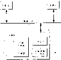
Figure 1A shows to use by data/address bus with the form of block diagram and links together the system that electronic equipment was constituted;
Figure 1B shows the further details of the part of system shown in Figure 1A with the form of block diagram;
Fig. 2 is the flow chart of the overall operation of expression locking mechanisms system;
Fig. 3 is the flow chart of expression first transaction type;
Fig. 4 is the flow chart of expression second transaction type;
Fig. 5 is the flow chart of expression the 3rd transaction type;
Fig. 6 is the flow chart of expression the 4th transaction type;
Fig. 7 is the flow chart of expression the 5th transaction type.
In the accompanying drawings, identical label is represented same or analogous device among the different figure.
Detailed description of the accompanying drawings
Figure 1A shows and comprises respectively three electronic equipment A, B representing with label 110,100 and 120 and the system of C, and these three equipment connect together by data/address bus 130.Device A, B and C can be various types of electronic equipments, comprise the consumer electronic devices such as audio frequency and/or video signal processing apparatus and family expenses control appliance.The particular instance of consumer electronic devices comprises TV (TV) receiver, display device, junction box, video tape recorder (VTR or VCR) direct broadcasting satellite receiver (as the DSS satellite receiver), CD (CD) equipment, digital video disk (DVD) equipment.The family expenses control appliance comprises security device (for example video camera, lock), remote control switch equipment and environmental control equipment (for example heater, refrigerator).The system that comprises the principle of the invention can comprise more than three equipment shown in Figure 1A.And each equipment all can be dissimilar equipment.For example, system of the present invention can comprise a plurality of equipment in the family, comprises TV, VCR, junction box, satellite receiver, audio system and family expenses control appliance.
In the example shown in Figure 1A, data/address bus 130 comprises a plurality of signal paths, so that Data transmission and control information between equipment.The structure of bus can be serial or parallel.Can be by any in the multiple bus protocol such as above-mentioned CEBus or IEEE1394 agreement Data transmission on bus.Draw together video and voice data via bus 130 data packets transmitted.For example, the satellite receiver of receiving digital video signal can reach Digital Video Tape Recorder (DTR) so that recorded with digital video and voice data via bus 130.
The aspect that bus interface 102 is controlled that microcomputer μ C104 is provided is to determine how to solve the conflicting request that the resource in the equipment 100 is used.For example, consider such situation, wherein, equipment 110 is junction boxs, and equipment 120 is DSS satellite receiver, and equipment 100 is video tape recorder (VTR).The user can programme so that record specific program via junction box 110 in the specific time to VTR100.Order that conflict arranged can make DSS equipment 120 attempt to use this VTR100 when VTR100 is just recording program via junction box 110.Common system is by ignoring DSS equipment 120 and attempt the use carried out or by notifying the user can not use VTR100 to solve the problems referred to above.
According to one aspect of the present invention, the system shown in Figure 1A has realized a lock management device, so that the conflict that solves resource by the following mode that explains detailedly.In the exemplary embodiment shown in Figure 1A, microcomputer μ C104 operates under the control of " lock management device " routine, to guarantee that equipment 100 can manage conflict by the mode of following detailed description, described " lock management device " is included in the bus control program.One " process locks ", 1070 routines are also included within the bus control program; The operation of the process that locks 1070 has been described in following detailed description to Fig. 2.Described lock management device be used to the connect correspondence between the equipment of bus 130 or the condition that locks, and be used to determine under which type of condition, to revise aforementioned relation.The operation of lock management device relates to some parameter, and these parameters are stored in the part 107 of memory 106, below will describe these parameters in detail.Relate to the lock management device zone 107 of memory 106 that the parameter that manage conflict be stored in Figure 1A in relevant with the relation of locking.Address and unlocking condition that three kinds of such parameters are the duration, be lockable.Figure 1B has illustrated this three parameters, they as three independently project 1071,1072 and 1073 be stored in the memory block 107.Should be realized that although do not show in Figure 1A, equipment 110 and 120 respectively comprises such performance, they can provide and the similar function of function as the equipment 102,104,106 in the equipment 100 and 107 provide as herein described.Structure in the equipment 110 and 120 can with the structure similar shown in the equipment 100, but also can produce similar function with other structure.
As the operational instances of lock management device, consider above-mentioned conflict example.Utilize described lock management device, the program of recording from junction box 110 with VTR100 relates to the bus mastering that VTR100 is passed in junction box 110 request of will locking.The request of locking requires VTR100 to form a kind of and relation junction box 110 promptly forms the condition that is lockable.Microcomputer 104 receives the above-mentioned request of locking by bus interface devices 102 and whether definite VTR100 is pinned by another device.If this VTR is not lockable, promptly this VTR can be used for locking, and then VTR100 just sends to junction box 110 and replys, and locks to show to have set up in the process of locking 1070.Will begin to carry out to recording of scheduled program from junction box 110, and, except the above-mentioned relation of locking some condition can prevent to record interruption, said some condition is to be limited by the parameter such as duration and unlocking condition, and, as following detailed description, said some condition is related with the above-mentioned relation of locking.The value of above-mentioned parameter is promptly to be initiated that the equipment of the condition of locking (being junction box 110 in this example) forms and be transferred into and be stored in the appropriate section in zone 107 of memory 106 of the equipment (being VTR in this example) that is lockable by the described lock device that adds.When DSS equipment 120 needed to use VTR100, the function of the lock management device in the DSS equipment can send a request of locking to VTR100.Because the relation of locking that is pre-existing in is arranged between VTR100 and junction box 110, the lock management device in the VTR100 can be handled from the request of locking of DSS120 and by the request of managing conflict of following mode according to the parameter that is stored in the existing condition that locks of VTR100.
Fig. 2 has illustrated the operation of the process that locks 1070 that matches with lock management device 107.Relation or locking that lock management device 107 pairs one " main equipment " is initiated manage.The process that locks 1070 is pinned two equipment simultaneously.When main equipment will initiate to lock, this equipment just sent an order to slave unit.Equipment can be in any state wherein when relating to the various states that adds lock control.Ellipse 210,220,230 and 240 among Fig. 2 has illustrated above-mentioned four kinds of above-mentioned states promptly: be not lockable, be lockable, unlocking request is hung up and change the lock pointer.The oval line of connection has illustrated the conversion between the above-mentioned state.Shown in Fig. 2 top, the lock management device can receive and comprise the request that locks with unlocking request.Shown in Fig. 2 bottom, but lock the process response request and produce replying such as " grant_lock " (allowing to lock) or " lock_in_use " (using lock).And the process of locking can produce the indication that makes mistakes/reset of a unlocking request and an equipment.
As shown in Figure 2, described system responses one request of locking and the state 210 that never is lockable converts the state 220 that is lockable to and send a grant_lock and reply.When the d/d lock of response, then take place to be back to the state 210 that is not lockable from the state 220 that is lockable.Locking release (promptly unblanking) then takes place in the conversion via state 230 and 240.Described system can respond a unlocking request and from state 220 to unlocking request suspended state 230.State 230 times, described system can handle the parameter such as duration parameter and unlocking condition, to determine whether and should locking discharge.If do not remove this lock, just send a Lock_in_use message, described system can be back to the state 220 that is lockable.If lock can be discharged, just send a release message, described system can convert state 240 to, and in this state, the address that is lockable or the pointer that locks all can become the address or the pointer that locks of the equipment that current request locks.Then, described system is converted to the state of being lockable 220 and sends out a grant_lock message.
Fig. 3 to 7 has illustrated the lock management device 107 and the process 1070 i.e. operation in the various transaction processes of equipment room under various conditions that locks.In Fig. 3, equipment B is not lockable, and the locking to device A is set up in equipment B response one from the request of locking of device A.
In Fig. 4, equipment B responds the previous request of locking and locks with equipment C, and, receive a request of locking that conflict is arranged from device A.The duration parameter is set to 0, this means that equipment B needn't ask to agree to remove the lock that comes from equipment C before locking in release and with device A again.Equipment B only need judge that the unlocking condition parameter is to determine whether to remove the locking with C.
In Fig. 5, the equipment B response is asked from before locking of equipment C and is pinned with equipment C, and, the duration parameter is changed to 1.Equipment B is also referred to as the unlocking request of " remove and inherit locking " to equipment C transmission one.Lock management device among the equipment C determines whether lock is removed.In Fig. 5, the message that equipment C determines to keep said lock and sends one " resource is used ", this message is transmitted to device A by equipment B.
Fig. 6 show except equipment C by remove equipment C responded to the locking of equipment B and to the request of locking of device A with Fig. 5 in the similar transaction of transaction (being duration=1).Therefore, equipment C can send a release message to equipment B, and subsequently, equipment B is authorized the locking of device A.
Fig. 7 shows a kind of like this affairs, in these affairs, equal under 0 the situation equipment B and equipment C in the duration and pin, and device A greets all lock management devices will lock to equipment B to show device A.Equipment C can will discharge equipment C and give device A to the lock notification of equipment B.Then, device A sends a locking request to equipment B, and, because the duration parameter is changed to 0, remove to remove lock with equipment B with indicating equipment C so equipment B can lock with device A and send a message to equipment C.
In addition, only add that lock device or main equipment need lock management device 107 and equipment that slave unit maybe can be lockable only uses the process of locking 1070 this situations also to belong to scope of the present invention.This system operation and system described herein similar.
Below will explanation relevant lock management device of the present invention aspect further details, comprise removing of this lock management device above done to illustrate those features.Only for simplicity, below describe situation about comprising based on using the CAL programming language in detail, still, should be realized that, also available any other suitable programming language comes replaced C AL programming language.The application example that use locks
The situation that locks and concern that needs except that those that had illustrated are already used below will be described.In first example, an equipment (" device A ") will download to the plurality of data bag in the remote equipment (" equipment B ").Device A does not wish to override the data of writing in the equipment B, until finishing download.Under normal circumstances, this function need all have segmented network service (Segmented Network Service) in two equipment.But according to the present invention, device A can form a kind of interim relation of locking, and this relation can guarantee that device A is unique equipment that can carry out write operation to equipment B.After having transmitted data, device A can stop above-mentioned lock the relation and to equipment B " release ".
In second example, the external equipment such as junction box is carried out a program timer event.The tape-feed of junction box meeting " pinning " VCR.This will make VCR be in recording mode, finishes or more preferably condition occurs until subscription time.Described junction box to VCR send a Stop (stopping) order and when described incident finishes to the VCR release.
In the 3rd example, an equipment will show an OSD (showing on the screen, i.e. ON SCREENDISPLAY) message a period of time.This equipment is oneself to pin display and send relevant display message.Described display device shows above-mentioned information a period of time.Described for example overtime and be unlocked by adding lock device itself or incident with good conditionsi by lock device.
Realized that also a kind of special shape that locks is " monitoring ".The interoperability of control and plurality of devices needs to know the state of these equipment.The equipment that comprises the monitoring ability can be differentiated the broadcasting that equipment the sent out report that one group of particular device for example is positioned at the house.
For example, state change information automatically can be sent to another equipment from an equipment.One VCR upgrades its operation mode state to a display device, and perhaps, a temperature sensor sends up-to-date information to environment manager.This process has two problems.First problem is to determine where report should be delivered to.Another corresponding problem is that described receiving equipment will determine that the information of which report is important to its function.Occur during report that this situation can be sent a plurality of examples at a plurality of subsystems in same house equipment such as the thermostat of same type or the security personnel's transducer.Need differentiate information source.Described monitor function can be realized this function.
Having multiple monitoring uses.Some has more dynamic than other.Environment control is that stable (static state) monitors an example of using.In this system, monitor function is static relatively after initial adjustment function.Reliable and the cheap device that this system need be used to monitor.Problem such as safety and special use is important.The configuration of described system is carried out when mounted and is changed seldom very continually.
This point is opposite fully with the A/V system.The A/V system is real dynamic.Equipment can mount and dismount continually.Video source and request function can make system configuration change rapidly and frequently.Play, record, display message and timer event all need change to the monitoring of equipment with aspect locking.Need and to become DBS equipment at once from the monitoring source device of VCR.The mutual monitoring of a large amount of equipment rooms also will be arranged.It is environmental system that TV can monitor an equipment, so that show when junction box is being monitored the state of VCR.
Required lock and monitoring has multiple rank.Under multiple situation, using only needs locking of a kind of device level.But, also have the example that will on object level, lock.(that is to say that an equipment can comprise more than one object, for example, an equipment can have multiple independently controllable function in this equipment.) one of this situation is that VCR uses, in this application, pin transmission mechanism and allow the miscellaneous equipment editor simultaneously or increase timer event.Similarly, although the display object that will pin among the TV is carried out appropriate display with assurance,, should not pin the responding ability of equipment to other communication.
Relevant, the with good conditionsi and feature inherited that the above-mentioned attribute that locks has.The example adding lock feature of having ready conditions be when equipment manufacture industry locked an object time.The object that is not lockable as yet can be lockable; But this equipment but can not lock.In this case, only can pin this equipment by the same equipment of one of locked object.Succession locks and is meant that all objects in the equipment have all inherited the state that is lockable of described object.
The lock management device
The all devices that pins miscellaneous equipment all must have one " lock management device " (LockManager), and it is followed the tracks of the situation of all activities of being initiated by the said equipment locks and is responsible for remote equipment is locked and release.The structure of this lock management device of being realized by CAL below has been described.
| The lock management device | (16) data table stores device | ||||
| For the formed lock of equipment provides central switching station | |||||
| IV | R/ V | Type | Title | The description list function | |
| a61) | R | n | Number_of_locks (lock number) | Size_of_memory (memory size) | |
| b(62) | R | n | Length_of_lock_ pointer (lock pointer length) | Length_of_record (length of record) | |
| C*(43) | R/W | n | Current_lock (current lock) | Current_index (current pointer) | |
| I*(6c) | R/W | d | Lock_pointer (lock pointer) | Memory_block (memory block) | |
Below above-mentioned parameter is described.The definition of (1.Lock_pointer lock pointer)
The record of the instance variable (IV) of each data storage memory_block (memory block) all is pointers, and its points to remote mode and resides in the equipment that is lockable on the network.Described Lock_pointer data comprise three territories: (1)<Device_Network_Address〉(device network address), (2)<Locked_Context_ID〉(the description list sign that is lockable), (3)<locked_Object_ID〉(object identity that is lockable).Those territories of representing with blank are considered to null (sky).
Territory, the said equipment network address is the network address of the equipment that is lockable.In CEBus uses, MAC Address is used as this network address.
The Locked_Context_ID territory comprises two bytes.First byte is to describe table number or description list asterisk wildcard " DE ".Table asterisk wildcard DE is meant said lock all examples corresponding to same description list in the equipment.Second byte is Context_Class_ID (description list class sign).Remaining byte is sky (null).
The locked_Object_ID territory is divided into two bytes.First byte is Object_Number (object number) or object asterisk wildcard " 00 ".When using the object asterisk wildcard, second byte is exactly Object_Class (object class).When not using above-mentioned asterisk wildcard, second byte is null just.This just can pin all objects in same target class (Object Class).2. release message definition
The above-mentioned equipment that is lockable sends a release message to the lock management device.Three kinds of release message that defined are arranged: (1) Device_Unlock (equipment release), (2) Context_Unlock (description list release), and (3) Object Unlock (object release).
Available Macro (grand) U4 sends release message.U4 is grand to comprise two argument territories.First argument comprises Device_Network_Address.Second argument comprises description list and object information.Described grand prototype is:
"<context_ID〉<object_ID〉U4<data token (data token)〉<size of data (size of data)〉<escape token 〉
<Device_Network_Address>F5><data token><size of data><escape token><Context_Number><Context_class_ID><Object_ID><Object_Class>”
When pinning a description list, Context_Number and Context_class_ID all are placed in above-mentioned second argument territory, (Object_ID and Object_Class are not provided).Described object information is null.
When pinning an object, Context_Number, Context_class_ID, Object_ID and Object_Class all provide in second argument.
A) equipment release message
Device_Unlock message must comprise the equipment that is lockable<Device_Network_Address 〉.Do not comprise above-mentioned second argument in this message.
“00 04 55 34 F5 F5 F4 34 F6<Device_Network_Address>F5”
Be placed on the example of the pointer vector that locks in the lock management device object
The equipment that locks
| The device network address | Locked_Conte xt_ID | Locked_Object_ID | |||
| First to fourth byte | The 5th byte | The 6th byte | The 7th byte | Eight characters joint | |
| The type of lock | Locked_Add ress | Conte xt_Nu mber or asterisk wildcard | Conte xt_Cl ass_I D | Object _ ID or asterisk wildcard | Null or Object_C lass |
| The equipment lock | Locked_Add ress | ||||
| The description list lock | Locked_Add ress | AO | (9F)* 0…9E | 01 | |
| Specific description list | Locked_Add ress | (DF)* AO..D E | (9F)* 0…9E | 01 | |
| All description lists of same description list class | Locked_Add ress | DE | (DF)* AO..D E | 01 | |
| All description lists in the equipment | Locked_Add ress | DE | 00 | 01 | |
| Object lock | Locked_Add ress | (DF)* AO..D E | (DF)* AO..D E | (3F)*0 1..3E | <any value 〉 |
| All objects in the description list class | Locked_Add ress | (DF)* AO..D E | (DF)* AO..D E | 00 | <any value 〉 |
The lock that the ability of an equipment pinning is depended on previous setting.Equipment locks and requires topped all other the lock that falls.
The process that locks has been used the variable in the following table (IV).In all processes, locking_address IV must be arranged.The default rank of duration is " 0 ".Following table has comprised the detailed description to IV.
| IV | R/W | Type | Title |
| B (24) | R/W | N | Persistence (duration) |
| E (45) | R/W | D | Key_Entry (key item) |
| G* (47) | R/W | D | Locking_Address (address locks) |
| O(4F) | R/W | D | Unlock_Condition (condition of unblanking) |
A) duration IV
Duration IV can influence the release behavior of equipment.Three kinds of duration levels that defined are arranged at present: (0) Loose (not strict or loose); (1) Tight (strictness) and (2) listening (monitoring).The default value of duration IV is Loose.When an equipment became the state that is not locked, it just should be set to default value the duration.
When duration value is " 0 ", the loose level that locks will appear.Loose locks and can cause an equipment that each equipment of attempting it is controlled is distinguished to some extent.But this combination is loose (loose).This means that the equipment that is lockable can allow the request of new locking and the lock device that adds before be sure oing is bound to remove already present locking.When the rank that locks was loose, the equipment that locks should automatically discharge said lock according to request.This can cause untiing apace previous lock and allow to carry out new locking.
When the equipment that pins in the loose mode received the request that changes Locking_address, this equipment will return a completed message and notify the equipment that had before locked to untie said lock.Loose locks and means that any equipment can change Locking_addressIV.
When duration field is set to " 1 ", tight (strictness) will occurs and lock.This makes that only adding lock device could change or allow to change Locking_addressIV.This point is useful when the 3rd equipment will be set up locking in the equipment that is lockable.In this case, the equipment that is lockable of the 3rd equipment query.The equipment that is lockable sends a release message to the lock management device object that adds lock device (Lock Manager Object).Add lock device and can generate lock and also can not generate lock, that is to say, add lock device and when removing previous lock, can return one and finish token (Completed Token) FE.Otherwise the lock management device is used (8) sign indicating number and is returned one and have and make mistakes _ resource FD token in use.
Duration IV is set to the form that locks that " 2 " can cause being called monitoring (as previously mentioned).In the process of monitoring, " being lockable " equipment can combine himself with another equipment.An equipment can be realized multiple duration value according to its application.
B) Key_EntryIV (key item IV)
Key_EntryIV can be used as a simple key that enters the equipment of being lockable.This IV can contact shielded variable.This selection can protect the privately owned function such as particular diagnostic and fitting operation not used at large.It also allows an equipment to differentiate different sources in monitoring application.
Key_EntryIV has two kinds of usages.First kind is the usage when formation tight locks (duration=1).Adding lock device provides the value of a data type variable Key_Entry, and this value is licensed the privately owned district of described equipment.This value is defined as " lock_key " for illustrative purposes.
Second kind is the usage of using in (duration=2) monitoring.Monitor function is used as an additional discriminator with Key_EntryIV.The back of this paper can illustrate the Key_Entry function.
Except first privately owned rank, the manufacturer can select Key_EntryIV is made the protected variable that need confirm.This will make a distinction the situation and the affirmation of specific use.When an equipment is not lockable or duration when not being arranged to " loose ", Key_EntryIV is inactive.Default Key_Entry value is " null ".When an equipment was not locked or the duration, rank changed, Key_EntryIV can revert to its default value.This equipment that will cause only locking can provide or read the value of Key_EntryIV.This allows to have only an equipment contact private data or function.
" lock_key " can be according to using but one is arranged on fixed key or the key write such as " trust key " among the ROM.Has only an effective Key_Entry value under the normal condition; But, a plurality of effective Key_EntryIV also can be arranged.The manufacturer can select lock_keyIV is made and can write.By remove said lock, maybe will hold the continuous time become<1, or Key_EntryIV is arranged to invalid item (for example logic length is 0) or a false (vacation) value, protected equipment can become privately owned once more.
C) Locking_AddressIV (address IV locks)
Locking_addressIV is a data type variable and is the network address of pinning the said equipment.In CEBus uses, MAC Address is used as the above-mentioned network address.
One adds lock device and can initiate locking to an equipment when writing into its network address in the suitable Locking_addressIV.In case a lock is in place, Locking_AddressIV is arranged to an invalid address (for example logic length is 0) this lock was lost efficacy.Do not support the request of locking of the equipment that locks can cause the invalid IV of a return value Error (invalid IV makes mistakes) to one.
D) Unlock_ConditionIV (condition of unblanking IV)
The 3rd variable is Unlock_ConditionIV, and it allows the user to specify will lock the condition of removing automatically.Unlocking condition can use the IV that can find in equipment, (this point and task manager object are similar).
Unlock_ConditionIV includes a Boolean expression, and this expression formula has been stipulated the unlocking condition to this equipment.Described Boolean expression is a CAL expression formula that is limited by the CAL grammer.This program is waited for and being occurred in equipment such as timer then or exceed some condition the threshold values.Described equipment is removed said lock according to the unlocking condition of appointment.Note that unlocking condition is positioned at the equipment that is lockable.Duration value can be loose or tight.
With the setArray method condition is loaded within the Unlock_Condition.In this case, loaded data is actual CAL condition program.This program comprises that the meeting that will wait for causes the condition of release activity.
As in the task manager object, in the CAL grammer, be used for aspect the Unlock_ConditionIV proper operation 2 differences a little being arranged.First is not both the instance variable that identification will be waited for.Description list and the object's position of IV must be provided, rather than a simple IV identifier.For example, Unlock_Condition always detect (Audiocontrol, Volume Control, current_value〉Audio Context, VolumeControl max_value), rather than detects (current_value〉max_value).Can come anolytic sentence correctly by requiring all bytes.
The Boolean expression that is included among the Unlock_Condition allows the two kinds of relations that will assess at the most.For example, when hour equaling 12 or when month equaling 6, clock object just can release.First IV in the above-mentioned Boolean expression is the value of being reported.Except that the relational operator of standard, stipulated that also an extra operator is the DELTA operator.Note that (using the setArray method) described object must be checked the validity that is placed on the condition among the IV when writing Unlock_ConditionIV.If this condition is invalid, just return an Error_BadArgument type (Error_ mistake argument type) (12), and, Unlock_Condition can not appear.The realization that locks
By Unlock_ConditionIV being arranged to an effective aim way address, just can pin an equipment with the setArray method.Under the situation that CEBus uses, the network address comprises element address and the house code that occurs in proper order by MSB, LSB.Example with the locking messages of cell codes 0034, house code 001A can cause following message:<context〉<object〉46 471 Ff5 Ff5 Ff4,34 Ff6,00 34 00 1A (<context〉<object〉setArray ' GA '<DEL〉<DEL〉<DATA〉34<ESCAPE〉0034 001A)
Object Locking_AddressIV is arranged to an invalid address (for example logic length is 0) can be with the object release.
(<context><object>setArray‘GA”<DEL><DEL><DATA>30<ESCAPE>
When not supporting this function, just return an Error-InvalidIV (mistake-invalid IV).
The realization that 1 object locks
By being set, the process of locking to realize locking on the object hierarchy in each object.
The realization that 2 description lists lock
Locking of above-mentioned object hierarchy can extend to description list.By being set, the process of locking to realize locking on the description list level in the description list controlling object.
Locking_AddressIV is arranged to an effective value can pins description list.The object that exemplifies in the description list has been inherited identical Locking_Address.(this be only applicable to the duration<2 o'clock.If) locked object in the description list, then can not pin this description list, the Locking_AddressIV that removes non-object is identical with the Locking_Address value of description list.
Write in the Context_Locking_AddressIV that places the description list controlling object by the whole address of the net that will add lock device, can initiate locking description list.
<context_ID>01 01 46 47 54 F5 F5 F4 34 F6<Locking_Address>
Context_Persistence (description list duration), a context_Key_Entry (description list lock), Context_Locking_Address (description list lock address) and Context_Unlock_Condition IV (description list unblank condition) are respectively from object IVPersistence, Key_Entry, their behavior of succession among Locking_Address and the Unlock_Condition.
The realization that 3 equipment lock
By being set, the process of locking to realize locking on the equipment level in node control object (Node Control Object).Described node control object can have the specialized object of oneself process that locks.The variable that locks on the described equipment level is:
| Node Control Object (node control object) | (01) Node Control (node control) | ||||
| The variable that permission equipment locks in the node control object | |||||
| IV | R/W | Type | Title | The description list function | |
| o(6Fh) | R | d | Object_list (Object table) | The tabulation of employed object in the description list | |
| z(6a) | R/W | N | Device_Persistence (equipment duration) | Duration | |
| v(76) | R/W | D | Device_Key_Entry (Device keys item) | Key_Entry (key item) | |
| T*(54) | R/W | D | Device_Locking_ Address (equipment lock address) | Locking_Address (address locks) |
| V(56) | R/W | D | Device_Unlock_ Condition (equipment unblank condition) | Unlock_Condition (condition of unblanking) |
Device_Persistence, Device_Key_Entry, Device_Locking_Address and Device_Unlock_Condition IV be respectively from object IVPersistence, and Key_Entry inherits their behavior among Locking_Address and the Unlock_Condition.
Write into Device_Locking_Address IV by the network address that will add lock device, can initiate equipment is locked.
00 01 46 54 F5 F5 F4,34 F6<Locking_Address〉scheme locks
For the purpose of illustrating, adding lock device is the equipment that will pin another equipment.By lock device is the equipment that will be lockable.The request of locking can be mail to the equipment that will be lockable or be mail to the lock management device that occupies lock.Under normal operation, can form a request of locking by attempting that Locking_AddressIV is write in a new address.This request can be directly also can be with good conditionsi.
A) request that directly locks
Example with the locking messages of cell codes (Unit Code) 0034, house code (House Code) 001A can cause following message:
<context><object>46 4741 Ff5 Ff5 Ff4 34 Ff6 00 34 001A(<context><object>setArray‘G’<DEL><DEL<DATA>‘4’<ESCAPE>0034 001A)
Equipment must determine whether it can pin.If do not pin the said equipment, object, description list less than pinning, just return a completed token.Add the lock device pointer that will lock and put lock management device object into.
B) the object with good conditionsi request of locking
Example with the locking messages of element number 0034, house sign indicating number 001A can cause following message:
<context><object>5647 F7<context><object>46 471 F5f5 Ff5Ff4 34 Ff6 00 34 00 1A EB 44 47 F8
<context><object>I(IF“G”<BEGIN> <context><object>setArray“G”<DEL><DEL<DATA>‘4’<ESCAPE>0034 001A<ELSE>setArray“G”<END>)
If array " G " (array " G ") is not used, just pin said equipment.Otherwise, just do not pin this equipment.This method can be with the resource use that locks.If described equipment uses, then send out request equipment can by send a broadcast to the device request that locks " greeting " so that the equipment that it abandons being lockable.
C) use the grand U2 of LOCK
The grand U2 of available LOCK pins description list and object.Grand message comprises grand ID, is argument list afterwards.Two essential arguments are arranged: 1) Locking_Address (address locks); And, 2) persistence (duration).If do not fill in argument list, just think that this argument list is null.After formation locks, upgrade Key_Entry (key item) and Unlock_CondirionIV (condition of unblanking).
<context_ID><object_ID>“U2”<data token><size ofdata><escape token><Locking_Address>F5<persistence>F5<Key_Entry>
The example that pins description list 11 with regard to the grand message of CAL is:
“11 011 55U 322 F4 34 F6 0F 32 23 34 F5 01”
Argument 0F,f32 2334 is the addresses that lock.Duration is set to 1.At this moment, add lock device and can send a Key_Entry (key item) IV data and Unlock_Condition (condition of unblanking) IV data.
When Locking_Address was not provided, just supposition was the source address of grand message.
" 11 01 55 32 F5 F5 01 "
Lock and discharge request
A) mail to locking of the main equipment that locks and discharge request
(1) with DISINHERIT (remove and inherit) (option one)
If at object, description list or the equipment level object of having locked, then this object can ask to hinder the device abandons that locks to lock.Message sends to lock management device object:
<Universal Context><Locking Manager Object>·disinherit<lock_pointer(6C)>F4[number of bytes]F6<device_address><context_id><object>
Remove right<device〉<context<object the succession that locks.
Described context_id is not if then comprise context_number for A0.If A0 then can randomly comprise the description table number.
(2) with the grand U41 of UNLOCK (option 21)
The grand U41 of UNLOCK is sent to EVENT Manager Object (task manager object).This grand with predetermined pointer that locks is complementary and asks this pointer of deletion.If the coupling of existing, so, lock management device or to the described request mandate or refuse this request.Add lock device if can not find, the equipment that then is lockable will be locked releasing.The details joint is seen the 2.1.2 joint.The realization of monitoring
Monitor function is corresponding with aforementioned method for reporting.Monitoring is implemented in to miscellaneous equipment or the interested object of Internet resources.An example of Internet resources is the time.
Monitor function can make an equipment differentiate the broadcast that comprises state information.Monitor function is the special applications that adds lock function.In listen mode, described object is not inherited the locking state of description list or equipment.(this correctly implements monitor function when equipment or description list are locked is essential).
In snoop procedure, an equipment combines self and another equipment.This means that an equipment can be provided with its Locking_AddressIV.Locking_AddressIV or read-only or read/write.Writing option actual is loose a type of locking.Duration IV is changed to " 2 ".Key_EntryIV can be used as special use discriminator.Following table has comprised monitoring IV tabulation.
| Object is monitored the IV tabulation | ||||
| IV | R/W | Type | Title | The description list function |
| G*(47) | R/W ** | D | Lock_Address (address locks) | The object listen address |
| B*(42) | R | N | Persistence (duration) | 2=monitors |
When Lock_Address was read-only variable, equipment just was provided with its address that locks.When from outer setting Locking_Address, add lock device and lock_pointer is not put into its lock management device.
Three kinds of different monitor methods are arranged.First method uses source network address to use the eavesdropping target with control.Described object support and the corresponding source device of Locking_AddressIV address are differentiated.In this case, message is write into suitable Instant Variable (instance variable).
Second kind and the third monitor method have used Key_Entry equipment.This method needs grand message.This grand message L1 is used for transmitting simultaneously Key_Entry value and data.Described audiomonitor is verified and saidly grandly is complementary from suitable address, source and the Key_Entry value that is provided and aforementioned desirable value.The implementation method that 1 multi-source is monitored
Having such situation is that the eavesdropping target will monitor all broadcast sources under situation about not differentiating.This situation will appear when it was just detecting fire alarm when fire perceiving device broadcasting.This transducer with information broadcast to network.Audiomonitor will be monitored all sources that may report fire alarm.
In general, receive the state of any equipment (transducer), can realize multi-source monitoring application by allowing an equipment.This point can be represented by Locking_AddressIV (element address IV) is set to a broadcast address.In CEBus uses, be arranged to all Unit_addressIV in the specific house code or be arranged to all addresses on the network monitoring discriminator.The source is sent in alarm or regional address is included in the described message; The address packet that source or zone are sent in alarm is contained in this message, takes out in source_address territory that this can be from be included in message or the state vector.2 monitor by Key_Entry and Locking_Address
In this way, the value of lock_key can become the value of a selector, and this value allows an equipment that indivedual description lists and object are differentiated.For example, in the time description list, can in MacroMessage (grand message), provide the time type identifier.Can check whether this value is required time type.If an equipment has a plurality of examples of report description list, this equipment just can comprise the description table number in the Key_Entry territory.The description table number that the receiving node inspection arrives also verifies whether this number is the number of being concerned about.<context_ID><object_ID>53 31 F4<size of data><escapetoken>5<Locking_Address>F5<data token><size of data><escapetoken><Key_Entry>F5<Argument_listmessage>
In snoop procedure, equipment combines self with another equipment.Monitoring in this case, an equipment can be provided with its Locking_AddressIV.Locking_AddressIV can be read-only or read/write.3 monitor by Key_Entry
Also can finish monitoring by Locking_Address being set to " 00 00 00 00 ".In this case, unique discriminator is the Key_Entry value.This just allows an object to differentiate according to access keys.Can accomplish this point as follows:
<context_ID><object ID>53 31 F5 00 00 00 00 F5<data token><size of data><escape token><Key_Entry>F5<Argument_list>
As Locking_Address when being read-only, described equipment just is provided with its address that locks in exclusive mode.When Locking_Address was read/write, described locking was loose type.Add lock device and a locking_pointer is not put into its lock management device.
<context_ID><object_ID>L1<data token><size of data><escapetoken><Locking_Address>F5 F5<message>
There is some example, in these examples, unique identifier arranged so that in a single equipment, differentiate a plurality of description lists or object.An example is the temperature sensor equipment that includes a plurality of transducers.Each transducer should be combined with corresponding eavesdropping target.This point realizes with the key_entry method.In said method, if then there is not discriminating in the key_entry=sky.When Key_Entry was set to certain value, audiomonitor needed correct Key_Entry value before upgating object.
Example: monitor the discriminator that variable has a similar key_entry number, it allows the user that one discriminator is set.Send described data and discriminator at Macro_ID key_entry F5 Listening DATA place.If Key_entry is not provided, then described discriminator is the network address.
Although understand the present invention in detail with reference to some embodiment,, as can be seen, according to reading and understanding to above content, concerning the expert of present technique, the alternative form of multiple the foregoing description can be arranged, comprised above-mentioned alternative form in the scope of appended claim.
Claims (12)
1. an equipment (B), this equipment comprises:
(a) be used for and second equipment (A) that at least one is interconnected by network-bus (130) thus communicate the device (102) of the relation of between above-mentioned first equipment and second equipment, setting up, described communicator can receive the data query from the 3rd electronic equipment;
(b) first device (106), it is used to store the information relevant with the duration of above-mentioned relation;
(c) second device (106), it is used to store and the relevant information of condition that is used for stopping above-mentioned relation;
(d) be used to respond from the control data of above-mentioned second equipment and device (104) that the operator scheme of described equipment is controlled, described control device can respond described data query handle the information of above-mentioned duration and can respond described end condition and handled duration information the two one of and stop above-mentioned relation.
2. equipment as claimed in claim 1, it is characterized in that, the described device that is used to control produces the information of treated duration, this information comprises a kind of in first kind of state and the second kind of state, in above-mentioned first kind of state, respond described data query and stop said relation, in above-mentioned second kind of state, no matter how said data query all still keeps above-mentioned relation.
3. equipment as claimed in claim 2 is characterized in that, the described device that is used to control responds described data query, stops said relation by form a kind of new relation between this equipment and the 3rd equipment.
4. equipment as claimed in claim 3 is characterized in that, described control device can respond inquires that to the reception of described data query above-mentioned second equipment is to obtain stopping the permission of described relation.
5. equipment as claimed in claim 4 is characterized in that described control device can also monitor the state of aforementioned second equipment.
6. equipment as claimed in claim 5 is characterized in that, described control device can also make above-mentioned second equipment change the information that is included in the described equipment.
7. equipment as claimed in claim 1 is characterized in that, the interior condition that described predetermined condition relates to relation between the aforementioned device and second equipment and described equipment in the two.
8. one kind is used for method that the consumer electronic devices that is connected on the network-bus is controlled, and this method comprises:
(a) and at least one communicate by second equipment that network-bus interconnects, thereby between the above-mentioned consumer electronic devices and second equipment, set up relation;
(b) operator scheme of described consumer electronic devices is controlled, had at least a kind of operator scheme to control, thereby between the above-mentioned consumer electronic devices and second equipment, set up relation by second equipment on the above-mentioned network-bus;
(c) storage information and the storage and the condition relevant predetermined condition that be used for stop above-mentioned relation relevant with the duration of above-mentioned relation;
(d) reception is from the data query of the 3rd equipment;
(e) handle information and the data query relevant with above-mentioned relation validity;
(f) a kind of in response above-mentioned end condition and the handled information and stop described relation.
9. method as claimed in claim 8 is characterized in that, described termination step also is included in and forms a kind of new relation between above-mentioned consumer electronic devices and the 3rd equipment.
10. method as claimed in claim 8 is characterized in that, above-mentioned second equipment of step response inquiry of described termination above-mentioned relation is implemented with the such step of permission that obtains the termination above-mentioned relation.
11. the method as claim 10 is characterized in that, this method comprises that also such step promptly monitors the state of above-mentioned second equipment.
12. the method as claim 11 is characterized in that, this method also comprises the step that can make above-mentioned second equipment change the information in the described consumer electronic devices that is included in.
Applications Claiming Priority (4)
| Application Number | Priority Date | Filing Date | Title |
|---|---|---|---|
| US2865196P | 1996-10-16 | 1996-10-16 | |
| US60/028,651 | 1996-10-16 | ||
| US3124996P | 1996-11-12 | 1996-11-12 | |
| US60/031,249 | 1996-11-12 |
Publications (2)
| Publication Number | Publication Date |
|---|---|
| CN1240548A CN1240548A (en) | 2000-01-05 |
| CN1115822C true CN1115822C (en) | 2003-07-23 |
Family
ID=26703948
Family Applications (1)
| Application Number | Title | Priority Date | Filing Date |
|---|---|---|---|
| CN97180666A Expired - Fee Related CN1115822C (en) | 1996-10-16 | 1997-10-16 | Device interoperability |
Country Status (8)
| Country | Link |
|---|---|
| US (1) | US6504847B1 (en) |
| EP (1) | EP0932958B1 (en) |
| JP (1) | JP4079335B2 (en) |
| KR (1) | KR100464170B1 (en) |
| CN (1) | CN1115822C (en) |
| AU (1) | AU4986197A (en) |
| DE (1) | DE69725598T2 (en) |
| WO (1) | WO1998017033A1 (en) |
Families Citing this family (62)
| Publication number | Priority date | Publication date | Assignee | Title |
|---|---|---|---|---|
| US6769128B1 (en) | 1995-06-07 | 2004-07-27 | United Video Properties, Inc. | Electronic television program guide schedule system and method with data feed access |
| US6469753B1 (en) | 1996-05-03 | 2002-10-22 | Starsight Telecast, Inc. | Information system |
| US9113122B2 (en) | 1997-04-21 | 2015-08-18 | Rovi Guides, Inc. | Method and apparatus for time-shifting video and text in a text-enhanced television program |
| ES2475242T3 (en) | 1997-07-21 | 2014-07-10 | Gemstar Development Corporation | Systems and methods for displaying and recording control interfaces |
| FR2779595B1 (en) | 1998-06-08 | 2000-07-21 | Thomson Multimedia Sa | METHOD FOR MANAGING PRIORITIES FOR ACCESS TO RESOURCES IN A HOME NETWORK AND APPARATUS FOR IMPLEMENTING SAME |
| US7013339B2 (en) | 1998-07-06 | 2006-03-14 | Sony Corporation | Method to control a network device in a network comprising several devices |
| EP0971506A1 (en) * | 1998-07-06 | 2000-01-12 | Sony International (Europe) GmbH | Method to control a network device in a network comprising several devices |
| JP2002520901A (en) * | 1998-07-06 | 2002-07-09 | ソニー インターナショナル (ヨーロッパ) ゲゼルシャフト ミット ベシュレンクテル ハフツング | How to perform scheduled actions on network equipment |
| US6252886B1 (en) | 1998-07-06 | 2001-06-26 | Sony Corporation | Bandwidth reservation |
| CN1867068A (en) | 1998-07-14 | 2006-11-22 | 联合视频制品公司 | Client-server based interactive television program guide system with remote server recording |
| US6820278B1 (en) * | 1998-07-23 | 2004-11-16 | United Video Properties, Inc. | Cooperative television application system having multiple user television equipment devices |
| US6898762B2 (en) | 1998-08-21 | 2005-05-24 | United Video Properties, Inc. | Client-server electronic program guide |
| MY124064A (en) * | 1998-09-14 | 2006-06-30 | Sony Corp | Information processing apparatus, information processing method, and recording medium |
| EP0987892B1 (en) * | 1998-09-14 | 2007-04-11 | Sony Corporation | Information processing apparatus, information processing method, and recording medium |
| JP2000156031A (en) * | 1998-11-17 | 2000-06-06 | Sony Corp | Information process system, information processor and information processing method |
| US6859799B1 (en) | 1998-11-30 | 2005-02-22 | Gemstar Development Corporation | Search engine for video and graphics |
| US7043138B1 (en) * | 1998-12-22 | 2006-05-09 | Sony Corporation | Broadcast receiver and system for performing copy prohibition and timed recording |
| JP4508330B2 (en) * | 1999-01-25 | 2010-07-21 | キヤノン株式会社 | Display device |
| JP4441945B2 (en) | 1999-05-07 | 2010-03-31 | ソニー株式会社 | Control method and control apparatus |
| WO2000070841A1 (en) * | 1999-05-19 | 2000-11-23 | Sony Corporation | Communication method, communication device, communication system and providing medium |
| JP4147689B2 (en) * | 1999-06-14 | 2008-09-10 | ソニー株式会社 | Information processing apparatus and information processing method |
| JP2001045030A (en) * | 1999-07-29 | 2001-02-16 | Nec Corp | Connection controller |
| US7032024B1 (en) * | 1999-07-29 | 2006-04-18 | Samsung Electronics Co., Ltd. | Connection management method for devices connected digital interface and command structure therefor |
| JP2001045031A (en) * | 1999-08-03 | 2001-02-16 | Seiko Epson Corp | Device to be logged in, log-in device, inter-device communication system provided with them, log-in control method and recording medium |
| JP2001243676A (en) * | 2000-02-29 | 2001-09-07 | Sony Corp | Device, method and medium for information processing |
| CN1606871A (en) | 2000-03-31 | 2005-04-13 | 联合视频制品公司 | Systems and methods for reducing cut-offs in program recording |
| US6754672B1 (en) * | 2000-09-13 | 2004-06-22 | American Management Systems, Inc. | System and method for efficient integration of government administrative and program systems |
| JP2004509518A (en) * | 2000-09-13 | 2004-03-25 | コーニンクレッカ フィリップス エレクトロニクス エヌ ヴィ | Communication systems and devices |
| US7103906B1 (en) | 2000-09-29 | 2006-09-05 | International Business Machines Corporation | User controlled multi-device media-on-demand system |
| JP2002108326A (en) * | 2000-09-29 | 2002-04-10 | Toshiba Corp | Video processor |
| CA2860962C (en) | 2000-10-11 | 2016-09-20 | United Video Properties, Inc. | Systems and methods for caching data in media-on-demand systems |
| CN101715109A (en) | 2000-10-11 | 2010-05-26 | 联合视频制品公司 | Systems and methods for providing storage of data on servers in an on-demand media delivery system |
| FR2819137A1 (en) * | 2000-12-28 | 2002-07-05 | Thomson Multimedia Sa | METHOD FOR MANAGING RECORDINGS OF AUDIOVISUAL PROGRAMS AND ASSOCIATED DEVICES |
| JP4104300B2 (en) * | 2001-06-25 | 2008-06-18 | 三洋電機株式会社 | Multiple equipment control system |
| US20040251887A1 (en) * | 2001-09-20 | 2004-12-16 | Sparrell Carlton J | Centralized resource manager with power switching system |
| GB0123349D0 (en) * | 2001-09-28 | 2001-11-21 | Koninkl Philips Electronics Nv | Audio and/or visual system method and components |
| KR100406857B1 (en) * | 2002-01-09 | 2003-11-21 | 엘지전자 주식회사 | Method of deciding configuration manager in home network |
| US7493646B2 (en) | 2003-01-30 | 2009-02-17 | United Video Properties, Inc. | Interactive television systems with digital video recording and adjustable reminders |
| JP2004336723A (en) * | 2003-04-17 | 2004-11-25 | Sharp Corp | Terminal apparatus and center apparatus, control method and control program thereof communication system, and recording medium recording these programs |
| US20060051059A1 (en) | 2004-09-08 | 2006-03-09 | Krakirian Haig H | Video recorder having user extended and automatically extended time slots |
| JP2005134975A (en) * | 2003-10-28 | 2005-05-26 | Sony Corp | Method, system and equipment for distributing information |
| US7584176B2 (en) * | 2004-03-10 | 2009-09-01 | Siebel Systems, Inc. | Methods and apparatuses to cancel query |
| US20070226344A1 (en) * | 2004-07-23 | 2007-09-27 | General Instrument Corporation | Centralized Resource Manager With Power Switching System |
| US20060080464A1 (en) * | 2004-09-14 | 2006-04-13 | Sony Corporation | System and method of utilizing a MAC address based unlocking key |
| US9973817B1 (en) | 2005-04-08 | 2018-05-15 | Rovi Guides, Inc. | System and method for providing a list of video-on-demand programs |
| US20070079342A1 (en) | 2005-09-30 | 2007-04-05 | Guideworks, Llc | Systems and methods for managing local storage of on-demand content |
| US7385478B2 (en) * | 2005-11-16 | 2008-06-10 | Honeywell International Inc. | Method and system of automatically generating global diagnostic statistics for a plurality of monitoring receivers at a master receiver |
| US9681105B2 (en) | 2005-12-29 | 2017-06-13 | Rovi Guides, Inc. | Interactive media guidance system having multiple devices |
| KR101320850B1 (en) * | 2006-12-21 | 2013-10-21 | 삼성전자주식회사 | Image display device for controlling external device by registering control ownership and method thereof |
| US7801888B2 (en) | 2007-03-09 | 2010-09-21 | Microsoft Corporation | Media content search results ranked by popularity |
| US8218734B2 (en) * | 2007-06-12 | 2012-07-10 | Microsoft Corporation | Messaging with a locked communication device |
| US20090019492A1 (en) | 2007-07-11 | 2009-01-15 | United Video Properties, Inc. | Systems and methods for mirroring and transcoding media content |
| US10063934B2 (en) | 2008-11-25 | 2018-08-28 | Rovi Technologies Corporation | Reducing unicast session duration with restart TV |
| EP2228944A1 (en) * | 2009-03-09 | 2010-09-15 | Alcatel Lucent | Method and system for remote configuration of a device |
| US9166714B2 (en) | 2009-09-11 | 2015-10-20 | Veveo, Inc. | Method of and system for presenting enriched video viewing analytics |
| US9014546B2 (en) | 2009-09-23 | 2015-04-21 | Rovi Guides, Inc. | Systems and methods for automatically detecting users within detection regions of media devices |
| US8464063B2 (en) * | 2010-03-10 | 2013-06-11 | Avaya Inc. | Trusted group of a plurality of devices with single sign on, secure authentication |
| KR20120023474A (en) * | 2010-09-03 | 2012-03-13 | 엘에스산전 주식회사 | System and method for firmware update of household appliances, and meter |
| US8805418B2 (en) | 2011-12-23 | 2014-08-12 | United Video Properties, Inc. | Methods and systems for performing actions based on location-based rules |
| US9400677B2 (en) * | 2013-01-02 | 2016-07-26 | Apple Inc. | Adaptive handling of priority inversions using transactions |
| US9674563B2 (en) | 2013-11-04 | 2017-06-06 | Rovi Guides, Inc. | Systems and methods for recommending content |
| EP3388901B1 (en) | 2017-04-10 | 2023-08-23 | Siemens Aktiengesellschaft | Safety-oriented automation system |
Family Cites Families (13)
| Publication number | Priority date | Publication date | Assignee | Title |
|---|---|---|---|---|
| CA1263721A (en) * | 1985-10-18 | 1989-12-05 | Owen Lloyd Nelson | Communication system for the transfer of small digital message blocks and large digital message blocks |
| US5031175A (en) * | 1989-09-15 | 1991-07-09 | Matsushita Electric Industrial Co., Ltd. | Communication control method for releasing communication apparatus from occupied state |
| US5343469A (en) * | 1990-06-14 | 1994-08-30 | Nec Corporation | Communication system and communication devices having lock function |
| EP0467305B1 (en) * | 1990-07-19 | 1997-07-02 | Sony Corporation | Apparatus for connecting electronic appliances |
| US5523748A (en) * | 1992-10-02 | 1996-06-04 | Nec Corporation | Method and apparatus for interrupting communication control units in an exclusive mode |
| JP3158364B2 (en) * | 1992-10-13 | 2001-04-23 | ソニー株式会社 | Electronics |
| JP3611588B2 (en) * | 1992-12-21 | 2005-01-19 | ソニー株式会社 | Transmission method, reception method, communication method, and bidirectional bus system |
| JPH06321029A (en) * | 1993-05-19 | 1994-11-22 | Alps Electric Co Ltd | Multiplex communication system |
| AU673756B2 (en) * | 1993-07-16 | 1996-11-21 | D2B Systems Company Limited | Communication bus system with mitigation of slave station locking problem |
| JP3307085B2 (en) * | 1993-12-10 | 2002-07-24 | ソニー株式会社 | Communication method and electronic equipment |
| US5689244A (en) * | 1994-06-24 | 1997-11-18 | Sony Corporation | Communication system and electronic apparatus |
| JP3348330B2 (en) * | 1995-04-21 | 2002-11-20 | ソニー株式会社 | Communication control method |
| US6300880B1 (en) * | 1996-01-16 | 2001-10-09 | Philips Electronics North America Corp. | Multichannel audio distribution system having portable receivers |
-
1997
- 1997-10-16 CN CN97180666A patent/CN1115822C/en not_active Expired - Fee Related
- 1997-10-16 WO PCT/US1997/018750 patent/WO1998017033A1/en active IP Right Grant
- 1997-10-16 JP JP51860298A patent/JP4079335B2/en not_active Expired - Fee Related
- 1997-10-16 DE DE69725598T patent/DE69725598T2/en not_active Expired - Lifetime
- 1997-10-16 US US09/269,243 patent/US6504847B1/en not_active Expired - Lifetime
- 1997-10-16 AU AU49861/97A patent/AU4986197A/en not_active Abandoned
- 1997-10-16 KR KR10-1999-7003227A patent/KR100464170B1/en not_active IP Right Cessation
- 1997-10-16 EP EP97912755A patent/EP0932958B1/en not_active Expired - Lifetime
Also Published As
| Publication number | Publication date |
|---|---|
| DE69725598D1 (en) | 2003-11-20 |
| AU4986197A (en) | 1998-05-11 |
| JP4079335B2 (en) | 2008-04-23 |
| DE69725598T2 (en) | 2004-04-29 |
| EP0932958A1 (en) | 1999-08-04 |
| KR20000049140A (en) | 2000-07-25 |
| JP2001508605A (en) | 2001-06-26 |
| US6504847B1 (en) | 2003-01-07 |
| WO1998017033A1 (en) | 1998-04-23 |
| KR100464170B1 (en) | 2004-12-31 |
| EP0932958B1 (en) | 2003-10-15 |
| CN1240548A (en) | 2000-01-05 |
Similar Documents
| Publication | Publication Date | Title |
|---|---|---|
| CN1115822C (en) | Device interoperability | |
| CN1181677C (en) | Digital television appts. for controlling peripheral device via digital bus | |
| US6507953B1 (en) | System and method for interfacing multiple electronic devices | |
| US7305680B2 (en) | Listening module for asynchronous messages sent between electronic devices of a distributed network | |
| EP1587316A2 (en) | Scheduled-recording method that schedules recording of copy-protected content | |
| EP2154869A2 (en) | Server architecture for network resource information routing | |
| EP0929170A3 (en) | Methods, systems and apparatus for providing device status information within a communication network | |
| US20100191833A1 (en) | Content and application download based on a home network system configuration profile | |
| CN1459958A (en) | Network forming method and apparatus | |
| CN1538709A (en) | Network control system for home appliances | |
| EP1769634A2 (en) | Methods and apparatus for hardware registration in a network device | |
| WO2005122174A1 (en) | Reservation device, reserved content recording instruction method, and recording device | |
| RU2316121C2 (en) | Device and method for providing notification about operation status of digital rights management | |
| US6298069B1 (en) | System and method for implementing self-device control modules in an electronic network | |
| US6477573B1 (en) | System and method for performing a hierarchical remote query in an electronic network | |
| EP2811690B1 (en) | Method and apparatus for managing wireless docking network | |
| CN100477612C (en) | Method for managing logical connections in a network of distributed stations, as well as a network station | |
| CN1193544C (en) | Communicating method and device thereof | |
| CN1274230A (en) | Data transmitting administrative method | |
| CN102571434B (en) | Data access control method for network driver layer in operating system | |
| JP2000261472A (en) | Illegal device detector | |
| TW201220114A (en) | Authority control systems and methods, and computer program products thereof | |
| JP2009129170A (en) | Device control apparatus and broadcast receiver equipped with the apparatus | |
| CN1215675C (en) | Signal processing system, signal input/output equipment and communication control method | |
| MXPA99003538A (en) | Device interoperability |
Legal Events
| Date | Code | Title | Description |
|---|---|---|---|
| C06 | Publication | ||
| PB01 | Publication | ||
| C10 | Entry into substantive examination | ||
| SE01 | Entry into force of request for substantive examination | ||
| C14 | Grant of patent or utility model | ||
| GR01 | Patent grant | ||
| CF01 | Termination of patent right due to non-payment of annual fee |
Granted publication date: 20030723 Termination date: 20161016 |
|
| CF01 | Termination of patent right due to non-payment of annual fee |