CN111397816A - PE valve air tightness test device - Google Patents
PE valve air tightness test device Download PDFInfo
- Publication number
- CN111397816A CN111397816A CN202010372758.3A CN202010372758A CN111397816A CN 111397816 A CN111397816 A CN 111397816A CN 202010372758 A CN202010372758 A CN 202010372758A CN 111397816 A CN111397816 A CN 111397816A
- Authority
- CN
- China
- Prior art keywords
- valve
- air
- fixedly connected
- bottom end
- inlet
- Prior art date
- Legal status (The legal status is an assumption and is not a legal conclusion. Google has not performed a legal analysis and makes no representation as to the accuracy of the status listed.)
- Pending
Links
Images


Classifications
-
- G—PHYSICS
- G01—MEASURING; TESTING
- G01M—TESTING STATIC OR DYNAMIC BALANCE OF MACHINES OR STRUCTURES; TESTING OF STRUCTURES OR APPARATUS, NOT OTHERWISE PROVIDED FOR
- G01M3/00—Investigating fluid-tightness of structures
- G01M3/02—Investigating fluid-tightness of structures by using fluid or vacuum
- G01M3/26—Investigating fluid-tightness of structures by using fluid or vacuum by measuring rate of loss or gain of fluid, e.g. by pressure-responsive devices, by flow detectors
- G01M3/28—Investigating fluid-tightness of structures by using fluid or vacuum by measuring rate of loss or gain of fluid, e.g. by pressure-responsive devices, by flow detectors for pipes, cables or tubes; for pipe joints or seals; for valves ; for welds
- G01M3/2876—Investigating fluid-tightness of structures by using fluid or vacuum by measuring rate of loss or gain of fluid, e.g. by pressure-responsive devices, by flow detectors for pipes, cables or tubes; for pipe joints or seals; for valves ; for welds for valves
Landscapes
- Physics & Mathematics (AREA)
- General Physics & Mathematics (AREA)
- Examining Or Testing Airtightness (AREA)
Abstract
The invention discloses a PE valve air tightness test device, which comprises: a base plate; the number of the support rods is four; the testing mechanism comprises four groups of pressing bases and inlet connectors, the pressing bases are located under the inlet connectors, detecting pipes are fixedly installed inside the pressing bases, the surfaces, extending to the outside of the pressing bases, of the detecting pipes are fixedly provided with pressure sensors and pressure display meters, and air inlet pipes are fixedly installed inside the inlet connectors; the invention has simple structure and convenient and rapid operation, can adjust the inflation and pressure maintaining time according to the air tightness requirements of the PE valves to be tested with different specifications, can simultaneously carry out air tightness detection on a plurality of PE valves, has intuitive judgment result, does not require high operation level of operators, has high detection efficiency, does not have any external force which additionally influences the test result on the PE valve to be tested, greatly improves the working efficiency and lightens the labor intensity.
Description
Technical Field
The invention relates to the technical field of PE valves, in particular to a PE valve air tightness test device.
Background
Valves are pipe fittings used to open and close pipes, control flow direction, regulate and control parameters (temperature, pressure and flow) of a transport medium, and are classified into shut-off valves, check valves, regulating valves, and the like according to their functions. The valve is a control part in a fluid conveying system, has the functions of stopping, regulating, guiding, preventing counter flow, stabilizing pressure, shunting or overflowing and relieving pressure and the like, is used for the valve of the fluid control system, and has quite a plurality of varieties and specifications from the simplest stop valve to various valves used in an extremely complicated automatic control system. The valve can be used for controlling the flow of various types of fluids such as air, water, steam, various corrosive media, slurry, oil products, liquid metal, radioactive media and the like. The valves are further classified into cast iron valves, cast steel valves, stainless steel valves (201, 304, 316, etc.), chrome molybdenum steel valves, chrome molybdenum vanadium steel valves, dual-phase steel valves, plastic valves, nonstandard valves, PE valves, etc. according to the material, and generally, in the production of PE valves, the PE valves after production need to be subjected to an air tightness test.
However, in the prior art, the air tightness of the PE valve is often detected manually, most of the PE valves are placed in water and then gas is introduced, so that the problems of low working efficiency, large error and the like exist, and the PE valves are easily damaged.
Disclosure of Invention
The invention aims to provide a PE valve airtightness test device to solve the problems in the background technology.
In order to achieve the purpose, the invention provides the following technical scheme: a PE valve air tightness test device comprises:
a base plate;
the number of the support rods is four;
the testing mechanism comprises four groups of pressing bases and inlet connectors, the pressing bases are located under the inlet connectors, detecting pipes are fixedly installed inside the pressing bases, the surfaces, extending to the outside of the pressing bases, of the detecting pipes are fixedly provided with pressure sensors and pressure display meters, and air inlet pipes are fixedly installed inside the inlet connectors;
a top plate;
a clamping mechanism;
a P L C controller;
the testing mechanism is fixedly arranged on the inner side of the supporting rods, and the P L C controller is fixedly arranged on the surface of one of the supporting rods;
the P L C controller is electrically connected with the pressure sensor.
Preferably, the method further comprises the following steps:
a partition plate;
wherein, the baffle is fixedly arranged on the inner side surface of the support rod.
Preferably, the clamping mechanism comprises a motor, the power output end of the motor penetrates through the top plate and is fixedly connected with a threaded screw rod, a sliding nut is slidably mounted outside the threaded screw rod, and a movable plate is fixedly mounted on the surface of the outer wall of the sliding nut;
the motor is fixedly installed on the top end surface of the top plate through bolts, the bottom end of the threaded screw rod is rotatably connected with the partition plate through a bearing seat, and the P L C controller is electrically connected with the motor.
Preferably, the method further comprises the following steps:
the buffer mechanism comprises a sleeve and a buffer rod, the buffer rod is slidably mounted in the sleeve, a spring is fixedly mounted at the bottom end in the sleeve, the bottom end of the buffer rod extends into the sleeve and is fixedly connected with a piston, and the piston is slidably connected with the sleeve;
the bottom end of the sleeve is fixedly connected with the top end of the inlet joint, and the top end of the buffer rod is fixedly connected with the bottom end of the moving plate.
Preferably, the testing mechanism further comprises an air pump, and an air delivery branch pipe is fixedly connected to the air delivery end of the air pump;
the air pump is fixedly installed on the top end surface of the top plate, and the P L C controller is electrically connected with the air pump.
Preferably, the method further comprises the following steps:
the alarm is fixedly arranged on the surface of one of the support rods;
and the alarm is electrically connected with the P L C controller.
Preferably, the surface of the upper end of the compression base is inlaid with a first sealing ring, and the surface of the bottom end of the inlet joint is inlaid with a second sealing ring.
Preferably, the top end of the detection tube extends to the upper end surface of the compression base, the bottom end of the detection tube penetrates through the compression base and is fixedly connected to the surface of the bottom plate, the bottom end of the air inlet tube extends to the bottom surface of the inlet joint, and the top end of the air inlet tube penetrates through the inlet joint and is fixedly connected with the air delivery branch tube.
Preferably, the gas transmission branch pipe is an elastic corrugated pipe.
Preferably, the end surfaces of the pressing base and the inlet joint are of conical structures.
Compared with the prior art, the invention has the beneficial effects that:
1. according to the invention, through the arranged test mechanism, the PE valve is vertically placed on the compression base, the lower end interface of the PE valve is inserted into the compression base, then the inlet joint moves downwards to the upper end interface of the PE valve, so that the communication among the inlet joint, the PE valve and the compression base can be realized, then the air pump works to input air into the air delivery branch pipe, then the air enters the PE valve through the air inlet pipe, then the air enters the detection pipe through the PE valve, meanwhile, the pressure value in the detection pipe can be set in the P L C controller in advance, when the air pressure in the detection pipe detected by the pressure sensor reaches a preset value, the air pump can be closed, the air delivery is stopped, the damage to the PE valve caused by excessive air delivery can be avoided, when the pressure in the detection pipe falls to a certain range, the system judges that the PE valve to be detected leaks air, the air tightness is unqualified, the alarm can give out an alarm, and meanwhile, the air pressure in the detection pipe can be observed through the pressure display table, so that the air tightness detection result of the PE valve can be known, and the air tightness of the.
2. The invention has simple structure and convenient and rapid operation, can adjust the inflation and pressure maintaining time according to the air tightness requirements of the PE valves to be tested with different specifications, can simultaneously carry out air tightness detection on a plurality of PE valves, has intuitive judgment result, does not require high operation level of operators, has high detection efficiency, does not have any external force which additionally influences the test result on the PE valve to be tested, greatly improves the working efficiency and lightens the labor intensity.
Drawings
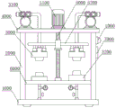
FIG. 1 is a schematic view of the overall structure of the present invention;
FIG. 2 is a schematic view of the internal structure of the present invention;
FIG. 3 is a top view of the present invention;
FIG. 4 is a schematic diagram of a moving plate structure according to the present invention;
FIG. 5 is a schematic view of the pressing base structure of the present invention;
FIG. 6 is a schematic view of an inlet fitting configuration of the present invention;
fig. 7 is a schematic structural diagram of a buffer mechanism of the present invention.
In the figure, the device comprises a 1000-bottom plate, a 2000-supporting rod, a 2100-alarm, a 3000-test mechanism, a 3100-air pump, a 3110-air delivery branch pipe, a 3200-pressing base, a 3300-inlet joint, a 3310-buffer mechanism, a 3311-sleeve, a 3312-buffer rod, a 3313-piston, a 3314-spring, a 3400-detection pipe, a 3500-pressure display meter, a 3600-first sealing ring, a 3700-second sealing ring, a 3800-air inlet pipe, a 3900-pressure sensor, a 4000-top plate, a 5000-clamping mechanism, a 5100-motor, a 5200-moving plate, a 5300-threaded screw rod, a 5400-sliding nut, a 6000-clapboard and a 7000-P L C controller.
Detailed Description
The technical solutions in the embodiments of the present invention will be clearly and completely described below with reference to the drawings in the embodiments of the present invention, and it is obvious that the described embodiments are only a part of the embodiments of the present invention, and not all of the embodiments. All other embodiments, which can be derived by a person skilled in the art from the embodiments given herein without making any creative effort, shall fall within the protection scope of the present invention.
Example 1:
referring to fig. 1-6, the present invention provides a technical solution, in which the PE valve airtightness testing apparatus includes a bottom plate 1000, a support rod 2000, a testing mechanism 3000, a top plate 4000, a clamping mechanism 5000, and a P L C controller 7000.
Wherein, bottom plate 1000 and roof 4000 are the circular structure.
Further, the bottom plate 1000 and the top plate 4000 may be made of a metal material such as iron, steel, stainless steel, or an alloy material.
Wherein, the support rods 2000 are provided with four.
Further, the support rod 2000 may be made of metal material or alloy material such as iron, steel, stainless steel, etc.
Wherein, four of these bracing pieces 2000 fixed connection are in bottom plate 1000 top all around, roof 4000 fixed connection is in four bracing piece 2000 top, test mechanism 3000 fixed mounting is in bracing piece 2000 inboard, P L C controller 7000 fixed mounting is in one of them bracing piece 2000 surface.
Wherein, the P L C controller 7000 is electrically connected with the pressure sensor 3900.
Wherein, test mechanism 3000 is equipped with four groups, test mechanism 3000 includes and compresses tightly base 3200 and entry joint 3300, compress tightly under base 3200 is located entry joint 3300, compress tightly fixed connection between base 3200 and the baffle 6000, it has test tube 3400 to compress tightly the inside fixed mounting of base 3200, test tube 3400 extends to and compresses tightly the outside fixed surface of base 3200 and installs pressure sensor 3900 and pressure display table 3500, the inside fixed mounting of entry joint 3300 has intake pipe 3800.
Further, the pressure sensor 3900 is model MIK-P300.
Further, the PE valve is vertically placed on the compressing base 3200, so that a lower end interface of the PE valve is inserted into the compressing base 3200, then the inlet joint 3300 moves downwards to an upper end interface of the PE valve, communication between the inlet joint 3300 and the compressing base 3200 can be achieved, then the air pump 3100 works to input air into the air transmission branch pipe 3110, then the air enters the PE valve through the air inlet pipe 3800, then the air passes through the PE valve and enters the detecting pipe 3400, meanwhile, a pressure value in the detecting pipe can be set in the P L C controller 7000 in advance, when the gas pressure in the detecting pipe detected by the pressure sensor 3900 reaches a preset value, the air pump 3100 can be closed, gas transmission is stopped, damage to the PE valve due to excessive gas transmission can be avoided, when the internal pressure of the detecting pipe falls to a certain range, the system judges that the PE valve to be detected leaks gas, the gas tightness is unqualified, the alarm 2100 gives an alarm, meanwhile, the gas pressure in the detecting pipe 3400 can be observed through the pressure display table 3500, the gas tightness detection result can be known, and the PE valve can be detected effectively.
Further, the compression mount 3200 and the inlet fitting 3300 are on the same vertical axis, enabling clamping of the PE valve.
Wherein, still include: and a separator 6000.
Wherein, the baffle 6000 is fixedly arranged on the inner side surface of the support rod 2000.
The clamping mechanism 5000 comprises a motor 5100, the power output end of the motor 5100 penetrates through the top plate 4000 and is fixedly connected with a threaded screw rod 5300, a sliding nut 5400 is slidably mounted on the outer portion of the threaded screw rod 5300, and a moving plate 5200 is fixedly mounted on the surface of the outer wall of the sliding nut 5400.
The motor 5100 is fixedly mounted on the top end surface of the top plate 4000 through bolts, the bottom end of the threaded screw rod 5300 is rotatably connected with the partition plate 6000 through a bearing seat, and the P L C controller 7000 is electrically connected with the motor 5100.
Further, the motor 5100 during operation can drive the screw rod 5300 and rotate, then can drive the slip nut 5400 and remove at screw rod 5300, when the motor 5100 drives the screw rod 5300 and clockwise rotates, the slip nut 5400 can move downwards, then can drive the inlet joint 3300 through the movable plate 5200 and move downwards, can accomplish the clamp to the PE valve, when the motor 5100 drives the screw rod 5300 and anticlockwise rotates, the slip nut 5400 can upwards move, then can drive the inlet joint 3300 through the movable plate 5200 and upwards move, can loosen the PE valve, exhaust, convenient operation is swift, traditional artifical fixed not enough has been replaced, can not cause the damage to the PE valve.
The testing mechanism 3000 further comprises an air pump 3100, and an air delivery branch pipe 3110 is fixedly connected to the air delivery end of the air pump 3100.
Further, operation of the air pump 3100 enables delivery of the PE valve gas.
The air pump 3100 is fixedly mounted on the top surface of the top plate 4000, and the P L C controller 7000 is electrically connected to the air pump 3100.
Wherein, still include: and the alarm 2100 is fixedly arranged on the surface of one of the support rods 2000.
Further, when the pressure in the detection tube 3400 is reduced to a certain range, the system judges that the PE valve to be detected leaks air, the air tightness is unqualified, the alarm 2100 gives an alarm sound, and people can be informed of the detection result at the first time.
Wherein, the alarm 2100 is electrically connected with the P L C controller 7000.
A first sealing ring 3600 is embedded on the surface of the upper end of the pressing base 3200, and a second sealing ring 3700 is embedded on the surface of the bottom end of the inlet joint 3300.
Further, No. one sealing washer 3600 and No. two sealing washers 3700 can ensure to compress tightly the leakproofness of being connected between base 3200 and the entry joint 3300 and the PE valve, avoid appearing the junction and have the condition of gas leakage, have guaranteed gas tightness test's accuracy.
The top end of the detection tube 3400 extends to the upper end surface of the pressing base 3200, the bottom end of the detection tube 3400 penetrates through the pressing base 3200 and is fixedly connected to the surface of the bottom plate 1000, the bottom end of the air inlet pipe 3800 extends to the bottom end surface of the inlet joint 3300, and the top end of the air inlet pipe 3800 penetrates through the inlet joint 3300 and is fixedly connected with the air conveying branch pipe 3110, so that the air inlet pipe 3800 and the air conveying branch pipe 3110 are communicated with each other.
Further, communication between the detection tube 3400, the PE valve and the air inlet tube 3800 can be achieved.
Wherein, the gas transmission branch pipe 3110 is specifically an elastic corrugated pipe.
Further, when the moving plate 5200 moves, it will also drive the inlet connector 3300 to move, and the air-conveying branch pipe 3110 will not affect the normal movement of the inlet connector 3300 due to its elasticity.
Wherein, the end surfaces of the compressing base 3200 and the inlet joint 3300 are both conical structures.
Further, the upper end of the compressing base 3200 is an interface with a guiding conical surface, and the lower end of the inlet connector 3300 is an interface with a guiding conical surface, so that the ports of the compressing base 3200 and the inlet connector 3300 are inserted into the two ports of the PE valve, thereby clamping and fixing the PE valve.
Synthesize above embodiment the device simple structure, convenient operation is swift, can require to adjust to aerify and pressurize time according to the gas tightness of the PE valve that awaits measuring of different specifications, can carry out the gas tightness of a plurality of PE valves simultaneously and detect, and the judgement result is directly perceived, does not require operating personnel to have high operation level, and detection efficiency is high, does not have any additional external force that influences the test result to the PE valve that awaits measuring, greatly improves work efficiency and alleviates intensity of labour.
Example 2:
referring to fig. 1, 2 and 7, the present invention provides a technical solution that a PE valve airtightness testing apparatus includes a bottom plate 1000, a support rod 2000, a testing mechanism 3000, a top plate 4000, a clamping mechanism 5000, and a P L C controller 7000.
Wherein, bottom plate 1000 and roof 4000 are the circular structure.
Further, the bottom plate 1000 and the top plate 4000 may be made of a metal material such as iron, steel, stainless steel, or an alloy material.
Wherein, the support rods 2000 are provided with four.
Further, the support rod 2000 may be made of metal material or alloy material such as iron, steel, stainless steel, etc.
Wherein, four of these bracing pieces 2000 fixed connection are in bottom plate 1000 top all around, roof 4000 fixed connection is in four bracing piece 2000 top, test mechanism 3000 fixed mounting is in bracing piece 2000 inboard, P L C controller 7000 fixed mounting is in one of them bracing piece 2000 surface.
Wherein, the P L C controller 7000 is electrically connected with the pressure sensor 3900.
Wherein, still include: the damper mechanism 3310.
Wherein, damper 3310 includes sleeve 3311 and buffer rod 3312, buffer rod 3312 slidable mounting is inside sleeve 3311, the inside bottom fixed mounting of sleeve 3311 has spring 3314, buffer rod 3312 bottom extends to inside and fixedly connected with piston 3313 of sleeve 3311, sliding connection between piston 3313 and the sleeve 3311.
Further, when the moving plate 5200 drives the inlet connector 3300 to move downward to the upper end interface of the PE valve, the moving plate 5200 acts on the buffering rod 3312, and when the inlet connector 3300 contacts the PE valve and stops moving, the buffering rod 3312 drives the piston 3313 to act on the spring 3314 to compress the spring 3314, and since the spring 3314 has very good elasticity, the damage to the PE valve when the inlet connector 3300 descends can be reduced, so that the inlet connector 3300 and the PE valve are in elastic contact, and the damage to the PE valve is avoided.
Wherein, the bottom end of the sleeve 3311 is fixedly connected with the top end of the inlet joint 3300, and the top end of the buffer rod 3312 is fixedly connected with the bottom end of the moving plate 5200.
Further, the inlet port 3300 is fixed to the bottom of the moving plate 5200 by a buffer mechanism 3310.
In combination with the above embodiments, the spring 3314 has excellent elasticity, so that damage to the PE valve caused by the lowering of the inlet 3300 can be reduced, and the inlet 3300 and the PE valve are in elastic contact with each other, thereby preventing the PE valve from being damaged.
In the several embodiments provided in the present invention, it should be understood that the disclosed apparatus may be implemented in other ways. The welding or screwing or winding of the parts to be welded or screwed together as shown or discussed can be assisted by means of devices such as welding torches, screwing with wrenches, etc., and the parts of the device can be made of various materials, such as metal materials, for example, aluminum alloys, steel and copper, by casting or by mechanical stamping.
It is noted that, herein, relational terms such as first and second, and the like may be used solely to distinguish one entity or action from another entity or action without necessarily requiring or implying any actual such relationship or order between such entities or actions. Also, the terms "comprises," "comprising," or any other variation thereof, are intended to cover a non-exclusive inclusion, such that a process, method, article, or apparatus that comprises a list of elements does not include only those elements but may include other elements not expressly listed or inherent to such process, method, article, or apparatus.
The above description is only an embodiment of the present invention, and not intended to limit the scope of the present invention, and all modifications of equivalent structures and equivalent processes performed by the present specification and drawings, or directly or indirectly applied to other related technical fields, are included in the scope of the present invention.
Claims (10)
1. The utility model provides a PE valve gas tightness test device which characterized in that includes:
a base plate (1000);
the number of the supporting rods (2000) is four;
the testing mechanism (3000), the testing mechanism (3000) is provided with four groups, the testing mechanism (3000) comprises a pressing base (3200) and an inlet joint (3300), the pressing base (3200) is located under the inlet joint (3300), a detection pipe (3400) is fixedly installed inside the pressing base (3200), a pressure sensor (3900) and a pressure display meter (3500) are fixedly installed on the surface of the detection pipe (3400) extending to the outside of the pressing base (3200), and an air inlet pipe (3800) is fixedly installed inside the inlet joint (3300);
a top plate (4000);
a clamping mechanism (5000);
a P L C controller (7000);
wherein, four of the supporting rods (2000) are fixedly connected to the periphery of the top end of the bottom plate (1000), the top plate (4000) is fixedly connected to the top ends of the four supporting rods (2000), the testing mechanism (3000) is fixedly arranged at the inner side of the supporting rods (2000), and the P L C controller (7000) is fixedly arranged on the surface of one of the supporting rods (2000);
wherein, the P L C controller (7000) is electrically connected with the pressure sensor (3900).
2. The PE valve airtightness testing apparatus according to claim 1, further comprising:
a separator (6000);
wherein, the clapboard (6000) is fixedly arranged on the surface of the inner side of the support rod (2000).
3. The PE valve airtightness testing apparatus according to claim 1, wherein: the clamping mechanism (5000) comprises a motor (5100), the power output end of the motor (5100) penetrates through the top plate (4000) and is fixedly connected with a threaded screw rod (5300), a sliding nut (5400) is slidably mounted outside the threaded screw rod (5300), and a moving plate (5200) is fixedly mounted on the surface of the outer wall of the sliding nut (5400);
the motor (5100) is fixedly mounted on the top end surface of the top plate (4000) through bolts, the bottom end of the threaded screw rod (5300) is rotatably connected with the partition plate (6000) through a bearing seat, and the P L C controller (7000) is electrically connected with the motor (5100).
4. The PE valve airtightness testing apparatus according to claim 1, further comprising:
the damping mechanism (3310) comprises a sleeve (3311) and a damping rod (3312), the damping rod (3312) is slidably mounted inside the sleeve (3311), a spring (3314) is fixedly mounted at the bottom end inside the sleeve (3311), the bottom end of the damping rod (3312) extends into the sleeve (3311) and is fixedly connected with a piston (3313), and the piston (3313) is slidably connected with the sleeve (3311);
the bottom end of the sleeve (3311) is fixedly connected with the top end of the inlet joint (3300), and the top end of the buffer rod (3312) is fixedly connected with the bottom end of the moving plate (5200).
5. The PE valve airtightness testing apparatus according to claim 1, wherein: the testing mechanism (3000) further comprises an air pump (3100), and an air delivery branch pipe (3110) is fixedly connected to the air delivery end of the air pump (3100);
the air pump (3100) is fixedly mounted on the top end surface of the top plate (4000), and the P L C controller (7000) is electrically connected with the air pump (3100).
6. The PE valve airtightness testing apparatus according to claim 1, wherein: further comprising:
the alarm (2100) is fixedly arranged on the surface of one of the support rods (2000);
wherein, the alarm (2100) is electrically connected with the P L C controller (7000).
7. The PE valve airtightness testing apparatus according to claim 1, wherein: a first sealing ring (3600) is embedded on the surface of the upper end of the pressing base (3200), and a second sealing ring (3700) is embedded on the surface of the bottom end of the inlet joint (3300).
8. The PE valve airtightness testing apparatus according to claim 1, wherein: the top end of the detection tube (3400) extends to the upper end surface of the pressing base (3200), the bottom end of the detection tube (3400) penetrates through the pressing base (3200) and is fixedly connected to the surface of the bottom plate (1000), the bottom end of the air inlet tube (3800) extends to the bottom end surface of the inlet joint (3300), and the top end of the air inlet tube (3800) penetrates through the inlet joint (3300) and is fixedly connected with the air transmission branch tube (3110).
9. The PE valve airtightness testing apparatus according to claim 5, wherein: the gas transmission branch pipe (3110) is specifically an elastic corrugated pipe.
10. The PE valve airtightness testing apparatus according to claim 1, wherein: the end surfaces of the pressing base (3200) and the inlet joint (3300) are of conical structures.
Priority Applications (1)
| Application Number | Priority Date | Filing Date | Title |
|---|---|---|---|
| CN202010372758.3A CN111397816A (en) | 2020-05-06 | 2020-05-06 | PE valve air tightness test device |
Applications Claiming Priority (1)
| Application Number | Priority Date | Filing Date | Title |
|---|---|---|---|
| CN202010372758.3A CN111397816A (en) | 2020-05-06 | 2020-05-06 | PE valve air tightness test device |
Publications (1)
| Publication Number | Publication Date |
|---|---|
| CN111397816A true CN111397816A (en) | 2020-07-10 |
Family
ID=71433602
Family Applications (1)
| Application Number | Title | Priority Date | Filing Date |
|---|---|---|---|
| CN202010372758.3A Pending CN111397816A (en) | 2020-05-06 | 2020-05-06 | PE valve air tightness test device |
Country Status (1)
| Country | Link |
|---|---|
| CN (1) | CN111397816A (en) |
Cited By (3)
| Publication number | Priority date | Publication date | Assignee | Title |
|---|---|---|---|---|
| CN111964899A (en) * | 2020-08-11 | 2020-11-20 | 王学义 | Valve leakage detection device for air conditioner production and use method thereof |
| CN113483963A (en) * | 2021-07-01 | 2021-10-08 | 青岛理工大学(临沂)管理委员会办公室 | Automatic detection device for air tightness of valve |
| CN114054263A (en) * | 2020-08-03 | 2022-02-18 | 龚海涛 | Oil applying device for inner wall of welded pipe |
-
2020
- 2020-05-06 CN CN202010372758.3A patent/CN111397816A/en active Pending
Cited By (4)
| Publication number | Priority date | Publication date | Assignee | Title |
|---|---|---|---|---|
| CN114054263A (en) * | 2020-08-03 | 2022-02-18 | 龚海涛 | Oil applying device for inner wall of welded pipe |
| CN111964899A (en) * | 2020-08-11 | 2020-11-20 | 王学义 | Valve leakage detection device for air conditioner production and use method thereof |
| CN111964899B (en) * | 2020-08-11 | 2022-08-30 | 理文科技(山东)股份有限公司 | Valve leakage detection device for air conditioner production and use method thereof |
| CN113483963A (en) * | 2021-07-01 | 2021-10-08 | 青岛理工大学(临沂)管理委员会办公室 | Automatic detection device for air tightness of valve |
Similar Documents
| Publication | Publication Date | Title |
|---|---|---|
| CN111397816A (en) | PE valve air tightness test device | |
| CN104568397A (en) | Multifunctional automatic performance testing device for low-temperature valve | |
| CN216559591U (en) | Be used for fire hose valve detection device | |
| CN217277501U (en) | Pipeline compressive capacity detection device | |
| CN212007700U (en) | PE valve air tightness test device | |
| CN117516823A (en) | Tightness detection equipment for valve processing | |
| CN219495596U (en) | Leak detection tool for high-pressure valve | |
| CN210322219U (en) | Pressure reducing valve air tightness detection device | |
| CN218765871U (en) | Be used for card pressure formula stainless steel pipe fitting gas tightness detection device | |
| CN117191295A (en) | Automatic inspection device for metal corrugated pipe leaving factory | |
| CN116679143A (en) | Electric power instrument safety inspection device with adjustable location | |
| CN110657982A (en) | Breather valve capability test system | |
| CN109506928A (en) | Valve pressure device and suppress test method | |
| CN210005241U (en) | simple valve pressure testing device | |
| CN210571763U (en) | On-spot withstand voltage detection device of PE pipe for gas | |
| CN219605586U (en) | Tightness detection device for water pump | |
| CN210953256U (en) | Device for testing sealing performance of heat meter and water meter | |
| CN209085869U (en) | A kind of equipment of gas source detection standpipe water collector sealing performance | |
| CN210571247U (en) | Valve detection device is used in pipeline valve processing | |
| CN207472487U (en) | A kind of detection device of pressure pipeline | |
| CN111693217A (en) | Device for verification test of valve core and valve cage sealing of side-discharge valve | |
| CN220419010U (en) | Pressure vessel pressure pipeline inspection detection device | |
| CN110987598A (en) | Water pressure testing frame | |
| CN209387423U (en) | A kind of pipeline valve pressure testing device | |
| CN215639992U (en) | Electric valve gas tightness detection device |
Legal Events
| Date | Code | Title | Description |
|---|---|---|---|
| PB01 | Publication | ||
| PB01 | Publication | ||
| SE01 | Entry into force of request for substantive examination | ||
| SE01 | Entry into force of request for substantive examination | ||
| CB03 | Change of inventor or designer information | ||
| CB03 | Change of inventor or designer information |
Inventor after: Wang Baoxing Inventor after: Li Gang Inventor after: Song Shubing Inventor before: Song Shubing Inventor before: Li Gang Inventor before: Wang Baoxing |