CN111337375A - Remote monitoring system for icing of power transmission line - Google Patents
Remote monitoring system for icing of power transmission line Download PDFInfo
- Publication number
- CN111337375A CN111337375A CN202010199330.3A CN202010199330A CN111337375A CN 111337375 A CN111337375 A CN 111337375A CN 202010199330 A CN202010199330 A CN 202010199330A CN 111337375 A CN111337375 A CN 111337375A
- Authority
- CN
- China
- Prior art keywords
- transmission line
- terminal
- transmitter
- signal
- electric quantity
- Prior art date
- Legal status (The legal status is an assumption and is not a legal conclusion. Google has not performed a legal analysis and makes no representation as to the accuracy of the status listed.)
- Pending
Links
Images


Classifications
-
- G—PHYSICS
- G01—MEASURING; TESTING
- G01N—INVESTIGATING OR ANALYSING MATERIALS BY DETERMINING THEIR CHEMICAL OR PHYSICAL PROPERTIES
- G01N5/00—Analysing materials by weighing, e.g. weighing small particles separated from a gas or liquid
-
- G—PHYSICS
- G01—MEASURING; TESTING
- G01B—MEASURING LENGTH, THICKNESS OR SIMILAR LINEAR DIMENSIONS; MEASURING ANGLES; MEASURING AREAS; MEASURING IRREGULARITIES OF SURFACES OR CONTOURS
- G01B7/00—Measuring arrangements characterised by the use of electric or magnetic techniques
- G01B7/02—Measuring arrangements characterised by the use of electric or magnetic techniques for measuring length, width or thickness
- G01B7/06—Measuring arrangements characterised by the use of electric or magnetic techniques for measuring length, width or thickness for measuring thickness
Abstract
The invention relates to a remote monitoring system for icing of a power transmission line, which comprises an automatic icing monitoring terminal and a control terminal; the ice coating automatic monitoring terminal is arranged on a power transmission line tower and is connected and communicated with the control terminal through a wireless network; the automatic icing monitoring terminal comprises a temperature acquisition transmitter, a humidity acquisition transmitter, a weighing data acquisition device, a signal filtering amplifier, an electric quantity management unit, a storage battery, a photovoltaic panel and an RTU remote terminal control unit. The invention has reasonable concept, safe and reliable use, can automatically calculate and monitor in real time, is not interfered by the outside, is convenient to operate and control, can provide data support for the ice-coated power transmission line at the first time, ensures the safe and reliable power supply of the power transmission line and reduces the operation risk of a power grid.
Description
Technical Field
The invention belongs to the technical field of power transmission line monitoring, and particularly relates to a real-time system for monitoring icing of a power transmission line.
Background
The ice and snow cover of the transmission line can cause the mechanical and electrical properties of the transmission line to be rapidly reduced, and serious electric power accidents such as conductor galloping, tower inclination and even collapse, disconnection, insulator string ice-covering flashover and the like are caused, so that the safe operation of an electric power system is seriously influenced. For a long time, long-term observation and research on the icing of the power transmission line are carried out at home and abroad, and a lot of achievements are obtained in the aspects of related technologies of icing theory, ice flashing mechanism, power transmission line icing monitoring research and the like. At present, methods for detecting ice coating on a line mainly comprise manual inspection monitoring, ice station observation and the like, and the methods have the problems of high labor intensity, high investment, long time, poor accuracy of monitoring results and the like in manual inspection.
For a long time, reliable and reliable monitoring of the icing condition of the power transmission line is a major bottleneck which troubles the operation and maintenance work of the power transmission line. Therefore, the key for solving the problems is to develop a remote monitoring system for ice coating of the power transmission line, particularly to improve the existing monitoring device.
Disclosure of Invention
Aiming at the problems in the prior art, the invention provides the ice-coating remote monitoring system for the power transmission line, which has the advantages of reasonable concept, safe and reliable use, real-time automatic calculation and monitoring, no external interference, convenient operation and control, capability of providing data support for the ice-coated power transmission line at the first time, capability of ensuring safe and reliable power supply of the power transmission line and reduction of the operation risk of a power grid.
The technical scheme of the invention is as follows:
the ice coating remote monitoring system for the power transmission line comprises an ice coating automatic monitoring terminal and a control terminal; the ice coating automatic monitoring terminal is arranged on a power transmission line tower and is connected and communicated with the control terminal through a wireless network; the automatic icing monitoring terminal comprises a temperature acquisition transmitter, a humidity acquisition transmitter, a weighing data acquisition device, a signal filtering amplifier, an electric quantity management unit, a storage battery, a photovoltaic panel and an RTU remote terminal control unit; one end of each of the temperature acquisition transmitter and the humidity acquisition transmitter is electrically connected with the electric quantity management unit, and the other end of each of the temperature acquisition transmitter and the humidity acquisition transmitter is electrically connected with the RTU remote terminal control unit; one end of the weighing data acquisition device is electrically connected with the electric quantity management unit, and the other end of the weighing data acquisition device is electrically connected with the signal filter amplifier; one end of the signal filter amplifier is electrically connected with the electric quantity management unit, and the other end of the signal filter amplifier is electrically connected with the RTU remote terminal control unit; the electric quantity management unit is used for realizing charge and discharge control between the photovoltaic panel and the storage battery; one end of the electric quantity management unit is connected with 220V mains supply through a mains supply interface, and the other end of the electric quantity management unit is respectively connected with the storage battery and the photovoltaic panel; one end of the RTU remote terminal control unit is connected with the power management unit, and the other end of the RTU remote terminal control unit is connected with the control terminal through a wireless network.
The transmission line icing remote monitoring system, wherein: the RTU remote terminal control unit respectively collects a weighing current signal of the weighing data acquisition device, a temperature current signal of the temperature acquisition transmitter and a humidity current signal of the humidity acquisition transmitter, and then transmits the signals to the remote computer expert software system through a wireless network.
The transmission line icing remote monitoring system, wherein: the RTU remote terminal control unit is provided with a switching value acquisition channel, an analog value acquisition channel and a parallel interface; the switching value acquisition channel and the analog value acquisition channel are connected and communicated with the control terminal through the parallel interface; the switching value acquisition channel is used for acquiring the current output switching state controlled by the electric quantity management unit; the analog quantity acquisition channel is used for acquiring central weighing data, temperature data, humidity data and meteorological data.
The transmission line icing remote monitoring system, wherein: the analog quantity acquisition channel is provided with a multi-way switch, a current/voltage transformer, an electric quantity transmitter, a sampling retainer, an A/D converter and a scalar calculator; one end of the multi-way switch is connected with the current/voltage transformer, and the other end of the multi-way switch is connected with one end of the electric quantity transmitter; the other end of the electric quantity transmitter is connected with one end of the sampling holder, the other end of the sampling holder is connected with one end of the A/D converter, the other end of the A/D converter is connected with one end of the scalar calculator, and the other end of the scalar calculator is connected with the parallel interface and is connected with the control terminal through the parallel interface.
The transmission line icing remote monitoring system, wherein: the switching value acquisition channel is provided with switches K1-K8, a signal converter and a photoelectric isolator; one end of each of the switches K1-K8 is connected with a 12V direct-current power supply, and the other end of each of the switches K1-K8 is connected with one end of the signal converter; the other end of the signal converter is connected with one end of the photoelectric isolator, and the other end of the photoelectric isolator is connected with the parallel interface and is connected with the control terminal through the parallel interface.
The transmission line icing remote monitoring system, wherein: the control terminal comprises a CPU, a serial interface, a 4GModbus module, a Modbus register, a read-only memory, a Random Access Memory (RAM), an interrupt control module and a timing technology module; the control terminal is also provided with a 4G Modem, and the data of the switching value acquisition channel and the data of the analog value acquisition channel are transmitted to a remote computer expert software system through the 4G Modem.
The transmission line icing remote monitoring system, wherein: the weighing data acquisition device comprises a shell, an elastic body arranged in the shell, a resistance strain gauge connected with the elastic body and a detection circuit connected with the resistance strain gauge; the elastic body, the resistance strain gauge and the detection circuit are assembled into a whole to be installed inside the shell in a matched mode.
The transmission line icing remote monitoring system, wherein: the signal filter amplifier amplifies and filters the electric signal transmitted by the weighing data acquisition device in equal proportion and converts the electric signal into a standard current signal of 4-20 mA; the signal filter amplifier is a diode basic amplifying circuit and is used for amplifying the output voltage mV level signal to be in the range of 0-5V.
The transmission line icing remote monitoring system, wherein: the temperature acquisition transmitter and the humidity acquisition transmitter are both four-wire current type transmitters; the temperature acquisition transmitter and the humidity acquisition transmitter are both JWSKE-6 series enhanced temperature and humidity transmitters.
Has the advantages that:
the remote monitoring system for the icing of the power transmission line is based on a dynamic data weighing method, has reasonable structural design, can master the icing condition of the line at any time by installing the automatic icing monitoring terminal on the iron tower in the area easy to ice and transmitting field data to the monitoring terminal through a wireless communication network, can realize pre-warning and alarm, and achieves the purposes of collecting the icing data in real time, mastering the icing condition and taking measures to reduce the icing accident loss of a power grid.
The remote monitoring system for icing of the power transmission line also has the following advantages:
(1) dual power supply and mains-supply priority intelligent switching
The system has dual power supply, when no external commercial power is available, the electric quantity management unit stores the electric energy generated by the photovoltaic panel to the storage battery and transmits the power supply to each front-end electric equipment according to the electric quantity condition of the storage battery; when commercial power is input on site, the electric quantity management unit automatically cuts off the electric quantity output of the storage battery and switches to the commercial power to supply to each electric device at the front end.
(2) Weighing acquisition and multiple sensor fusion
The digital quantification of load is realized on site through an elastic element, a resistance strain gauge and a measuring circuit in the weighing data acquisition device, and a linear resistance signal is converted into a 4-20mA standard analog signal through a signal filter amplifier.
(3) System architecture model
The system adopts a distributed framework, the front end of the system can be arbitrarily provided with an ice coating automatic monitoring terminal, real-time data acquisition, cloud storage and multi-client monitoring and management functions are realized through network signals and cloud computing expert software, so that teams and related responsible persons can master the ice coating condition of the line at the first time, and necessary technical support is provided for building a strong intelligent power grid.
Drawings
Fig. 1 is a schematic block diagram of the remote monitoring system for ice coating on the power transmission line of the present invention.
Fig. 2 is a schematic diagram of the remote monitoring system for ice coating of the power transmission line.
Fig. 3 is a schematic circuit connection diagram of the ice coating remote monitoring system for the power transmission line of the invention.
Fig. 4 is a schematic structural diagram of a weighing data acquisition device of the remote monitoring system for ice coating of the power transmission line.
Fig. 5 is a circuit diagram of a weighing and collecting device of an ice coating automatic monitoring terminal of the remote monitoring system for ice coating of the power transmission line.
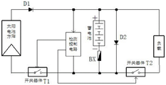
Fig. 6 is a circuit diagram of an electric quantity management unit of an ice coating automatic monitoring terminal of the electric transmission line ice coating remote monitoring system of the present invention.
Fig. 7 is a photoelectric isolation circuit diagram of an analog quantity acquisition channel of an RTU remote terminal control unit of the transmission line icing remote monitoring system of the present invention.
Detailed Description
As shown in fig. 1 and 2, the remote monitoring system for ice coating of the power transmission line comprises an automatic ice coating monitoring terminal 1 and a control terminal 2.
The ice coating automatic monitoring terminal 1 is installed on a power transmission line tower and is connected with the control terminal 2 for communication through a wireless network.
The control terminal 2 comprises a CPU, a serial interface, a 4G Modbus module, a Modbus register, a Read Only Memory (ROM), a Random Access Memory (RAM), an interrupt control module and a timing technology module.
The ice coating automatic monitoring terminal 1 comprises a temperature acquisition transmitter 11, a humidity acquisition transmitter 12, a weighing data acquisition device 13, a signal filtering amplifier 14, an electric quantity management unit 15, a storage battery 16, a photovoltaic panel 17 and an RTU remote terminal control unit 18.
One end of the temperature acquisition transmitter 11 and one end of the humidity acquisition transmitter 12 are electrically connected with the electric quantity management unit 5, and the other ends are electrically connected with the RTU remote terminal control unit 18. The temperature acquisition transmitter 11 and the humidity acquisition transmitter 12 are both four-wire (4-20mA) current type transmitters; the temperature acquisition transmitter 11 and the humidity acquisition transmitter 12 are enhanced temperature and humidity transmitters (temperature and humidity sensors) of the type JWSKE-6 series.
As shown in fig. 4, one end of the weighing data acquisition device 13 is electrically connected to the power management unit 15, and the other end is electrically connected to the signal filter amplifier 14. The weighing data acquisition device 13 includes a housing 130, an elastic body 131 disposed inside the housing 130, a resistance strain gauge 132 connected to the elastic body 131, and a detection circuit 133 connected to the resistance strain gauge 132; the elastic body 131, the resistance strain gauge 132 and the detection circuit 133 form a whole; when the lead is iced, the load of the lead generates an increment, the elastic body 131 deforms under stress, the resistance strain gauge 132 is attached to the elastic body 131, and the resistance strain gauge 132 on the upper part of the resistance strain gauge 132 deforms along with the deformation of the elastic body 131 to cause the resistance to change; the detection circuit 133 detects the resistance change of the resistance strain gauge 132, converts the resistance change into an electric signal proportional to the magnitude of the external force, and outputs the electric signal to the signal filter amplifier 14; specifically, the weighing data acquisition device 13 outputs a small voltage mV level signal, which is amplified to a range of 0 to 5V by the signal filter amplifier 14.
The resistance strain gauge 132 is formed by mechanically distributing a resistance wire on a substrate made of an organic material. The elastic body 131 has two functions, firstly, the elastic body 131 bears the external force to generate a reaction force to the external force to achieve a relative static balance, and secondly, the elastic body 131 generates a high-quality strain field (area) to enable the resistance strain gauge 132 adhered to the area to ideally complete the task of converting the strain electrical signal. The sensing circuit 133 is used to convert the resistance change of the resistive strain gauge 132 into a minute voltage output, such as: the sensitivity of the detection circuit 133 is 2 ± 0.002(mV/v), and under a certain power supply condition Uin (such as 12VDC), the ratio of the output variation Uout (such as 24mV) to the power supply voltage when the load reaches a rated full scale (such as 5000 kg).
The working principle of the weighing data acquisition device 13 is as follows: the elastic body 131 (elastic element, sensitive beam) generates elastic deformation under the action of external force, so that the resistance strain gauge 132 (conversion element) adhered to the surface of the elastic body is also deformed, the resistance value of the deformed resistance strain gauge 132 is changed (increased or decreased), and the resistance change is converted into an electric signal (voltage or current) through the corresponding detection circuit 133, so that the process of converting the external force into the electric signal is completed, the detection circuit 133 detects the change of the resistance strain gauge 132 and converts the electric signal into the electric signal proportional to the external force to be output, and the electric signal displays the quality of the measured object in a digital form after being processed, namely: force variation- > elastomer deformation- > resistance variation- > voltage variation.
As shown in fig. 5, the detection circuit 133 of the weighing data acquisition device 13 is composed of a chip U1, a chip U2, a chip U5, capacitors C1 to C11, an inductor L1, diodes D1 to D2, resistors R1 to R22, operational amplifiers U3A and U3B, photocouplers U4 and U6, and terminals P1 to P5. The capacitors C1-C3 and C5 are polar capacitors, and the resistors R7, R11, R16 and R20 are adjustable resistors; the diode D2 is a zener diode. The capacitor C1 adopts a C470uF/50V capacitor, the capacitor C2 adopts a C470uF/25V capacitor, the capacitor C3 adopts a 100uF/25V capacitor, and the capacitor C5 adopts a 68uF/16V capacitor; the capacitance values of the capacitors C4, C6, C7, C9, C10 and C11 are all 0.1uF, and the capacitance value of the capacitor C8 is 1 uF. The resistances of the resistors R1 and R14 are both 3K Ω, the resistances of the resistors R2 and R15 are both 20K Ω, the resistances of the resistors R3, R17, R21 and R22 are all 2K Ω, the resistances of the resistors R4, R5, R8, R10 and R12 are all 1K Ω, the resistances of the resistors R6, R13 and R18 are all 100K Ω, the resistance of the resistor R7 is 5K Ω, the resistances of the resistors R9 and R19 are all 10K Ω, the resistances of the resistors R11, R16 and R20 are all 50K Ω, and the resistance of the resistor R15 is 3K Ω. The inductance value of the inductor L1 was 47 uH.
As shown IN fig. 5, the model of the chip U1 is L7815ABD2T, pin IN of the chip U1 is connected to +24V power supply, pin GND of the chip U1 is grounded, and pin OUT of the chip U1 is connected to +15V power supply; the anode of the capacitor C1 is connected with a +24V power supply, and the cathode is grounded GND; the anode of the capacitor C2 is connected with a +15V power supply, and the cathode is grounded GND; the anode of the capacitor C3 is connected with a +15V power supply, and the cathode is grounded GND; one end of the capacitor C4 is connected to a +15V power supply, and the other end is grounded GND.
As shown in fig. 5, the model of the chip U2 is MAX764, the pin OUT of the chip U2 is connected to a-5V power supply, the pin FB and the pin REF of the chip U2 are connected to the capacitor C6 and are grounded through the capacitor C6, the pin SHDN and the pin GND of the chip U2 are both grounded, the pin V + of the chip U2 is connected to a +15V power supply, and the pin LX of the chip U2 is connected to the cathode terminal of the diode D1; the type of the diode D1 is N5817, and the anode end of the diode is connected with a-5V power supply; the inductor L1 is 47uH, one end of the inductor is connected with the cathode end of the diode D1, and the other end of the inductor is grounded; the anode of the polar capacitor C5 is grounded, and the cathode is connected with a-5V power supply.
As shown in fig. 5, one end of the capacitor C7 is connected to the +15V power supply, and the other end is grounded to GND; one end of the capacitor C8 is grounded, and the other end is connected with the No. 1 pin of the connecting terminal P2; the diode D2 is model IN4740, and its anode terminal is grounded and its cathode terminal is connected to pin No. 1 of the connecting terminal P2.
As shown in FIG. 5, the chip U5 has model number of OPA2227, pin + VCC of the chip U5 is connected to +15V power supply, pin-VCC of the chip U5 is connected to-5V power supply; one end of the resistor R4 is connected with the No. 1 pin of the connecting terminal P2, and the other end is connected with the pin OUT1 of the chip U5; one end of the resistor R8 is connected with a pin + IN1 of the chip U5, and the other end is connected with a No. 1 pin of a connecting terminal P3; one end of the resistor R12 is connected with a pin + IN2 of the chip U5, and the other end is connected with a No. 2 pin of a connecting terminal P3; one end of the resistor R5 is connected with the slide sheet of the resistor R7, and the other end is connected with the resistors R10 and R13 in series in sequence and then grounded; one end of the coil of the resistor R7 and the slide sheet are both connected with the resistor R6 and are both connected with a pin OUT1 of the chip U5 through a resistor R6, and the other end of the coil of the resistor R7 is connected between a resistor R10 and a resistor R13; one end of the capacitor C9 is connected with the No. 1 pin of the wiring terminal P3, and the other end is grounded; one end of the capacitor C10 is connected with a signal terminal S-of the weighing sensor, and the other end is grounded; one end of the resistor R18 is grounded, and the other end is connected with the slide sheet of the resistor R16; one end of the coil of the resistor R16 is connected to pin 1 of the terminal P3, and the other end of the coil is connected to pin 2 of the terminal P3.
As shown in fig. 5, pin 1 of the connection terminal P1 is connected to +24V power supply, and pin 2 is grounded; the No. 2 pin of the wiring terminal P2 is connected with a-5V power supply; the pin 1 of the terminal P4 is connected to +15V power supply, and the pin 2 is grounded.
As shown in fig. 5, one end of the capacitor C11 is connected to a +15V power supply, and the other end is grounded. The model of the operational amplifier U3A is LM358M, the positive pole end of the power supply is connected with a +15V power supply, and the negative pole end of the power supply is grounded; the non-inverting input end of the operational amplifier U3A is connected with a resistor R2 and is connected with the No. 1 pin of a connecting terminal P2 through a resistor R2, and the inverting input end of the operational amplifier U3A is connected with a slide sheet of a resistor R11; one end of a coil of the resistor R11 is grounded, and the other end of the coil is connected with a resistor R9 and is connected with a +15V power supply through a resistor R9; the output end of the operational amplifier U3A is connected with a resistor R3 and is connected with the anode end of a photoelectric coupler U4 through a resistor R3; the cathode end and the emitter of the photoelectric coupler U4 are grounded, and the collector of the photoelectric coupler U4 is connected with the No. 1 pin of the connecting terminal P5; one end of the resistor R1 is connected with the No. 1 pin of the wiring terminal P5, and the other end is connected with a +24V power supply; one end of the resistor R21 is grounded, and the other end is connected with the anode end of the photocoupler U4.
As shown in fig. 5, the operational amplifier U3B is model LM358M, the positive terminal thereof is connected to +15V power, the negative terminal thereof is grounded, the non-inverting input terminal thereof is connected to the resistor R15 and is connected to pin No. 1 of the connecting terminal P2 through the resistor R15; the inverting input end of the operational amplifier U3B is connected with the slide sheet of the resistor R20, one end of the coil of the resistor R20 is connected with the resistor R19 and is connected with a +15V power supply through the resistor R19, and the other end of the coil of the resistor R20 is grounded; the output end of the operational amplifier U3B is connected with a resistor R17 and is connected with the anode end of a photoelectric coupler U4 through a resistor R17; the cathode end and the emitter of the photoelectric coupler U4 are grounded, and the collector of the photoelectric coupler U4 is connected with the No. 2 pin of the connecting terminal P5; one end of the resistor R22 is connected with the anode end of the photoelectric coupler U4, and the other end is grounded; one end of the resistor R14 is connected with pin No. 2 of the connecting terminal P5, and the other end is connected with a +24V power supply.
As shown in fig. 5, Vout in the detection circuit 133 is a signal filtering amplifier that filters mv-level signals and then amplifies the signals, and the analog quantity output after amplification is 0-10V, and the output voltage can also be adjusted; s + and S-are signals of a weighing data acquisition device 13; OUT1 and OUT2 are switching value outputs, can be used for overweight alarm and can be adjusted.
One end of the signal filter amplifier 14 is electrically connected with the electric quantity management unit 15, and the other end is electrically connected with the RTU remote terminal control unit 18; wherein, the signal filter amplifier 14 amplifies the electric signal transmitted by the weighing data acquisition device 13 in equal proportion, filters the electric signal and converts the electric signal into a standard current signal of 4-20 mA; the signal filter amplifier 14 is a diode basic amplifying circuit, and mainly outputs a signal of a level of a minute voltage mV, and the signal of the level of the minute voltage mV is amplified to a range of 0 to 5V by the signal filter amplifier 14.
The electric quantity management unit 15 mainly realizes the charge and discharge control of the photovoltaic panel 17 and the storage battery 16 and adopts market molding products; one end of the electric quantity management unit 15 is connected with 220V commercial power through a commercial power interface, and the other end is respectively connected with the storage battery 16 and the photovoltaic panel 17. As shown in fig. 6, the power management unit 15 is composed of a solar battery pack, switching devices T1 and T2, a detection control circuit, a secondary battery, a resistor BX, diodes D1 and D2; the circuit of the power management unit 1 adopts the existing circuit, for example, the circuit is adopted by solar street lamps, solar monitoring devices and the like, and the function of the circuit is to convert light energy into electric energy and control the on-off of a load.
One end of the switch device T1 is connected with the cathode of the solar battery pack, and the other end is connected with one end of a switch device T2; the other end of the switching device T2 is connected with one end of a load; the anode end of the diode D1 is connected with the anode of the solar battery pack, and the cathode end of the diode D1 is connected with the other end of the load; one end of the detection control circuit is connected between the switching devices T1 and T2, and the other end of the detection control circuit is connected with the cathode end of the diode D1; the output end of the detection control circuit is also respectively connected with the switching devices T1 and T2; one end of the storage battery is connected with the resistor BX and is connected between the switching devices T1 and T2 through the resistor BX, and the other end of the storage battery is connected with the cathode end of the diode D1; the anode terminal of the diode D2 is connected to the cathode terminal of the diode D1, and the cathode terminal of the diode D2 is connected between the switching devices T1 and T2.
One end of the RTU remote terminal control unit 18 is connected with the power management unit 5, and the other end is connected with the control terminal 2 through a wireless network (GPRS/3G/4G). The RTU remote terminal control unit 18 collects the weighing current signal of the weighing data acquisition device 13, the temperature current signal of the temperature acquisition transmitter 11 and the humidity current signal of the humidity acquisition transmitter 12, respectively, and then transmits them to the remote computer expert software system through the wireless network (GPRS/3G/4G).
As shown in fig. 3, the RTU remote terminal control unit 18 has a switching value acquisition channel, an analog value acquisition channel and a parallel interface. The control terminal 2 is also equipped with a 4G Modem which transmits data of the switching value acquisition channels DI1-DI8 and the analog value acquisition channels AI1-AI8 to a remote computer expert software system through the 4G Modem.
The switching value acquisition channel and the analog value acquisition channel are connected and communicated with the control terminal 2 through parallel interfaces; the switching value acquisition channel is used for acquiring the state (on or off) of a plurality of paths of current output switches controlled by the electric quantity management unit 15. The switching value acquisition channel is provided with switches K1-K8, a signal converter and a photoelectric isolator; one end of each of the switches K1-K8 is connected with a 12V direct current power supply, and the other end of each of the switches K1-K8 is connected with one end of a signal converter; the other end of the signal converter is connected with one end of the photoelectric isolator, and the other end of the photoelectric isolator is connected with the parallel interface and is connected with the control terminal 2 through the parallel interface.
The switching values of the switches K1 to K8 are signals which vary discretely with time, generally have two states of "on" and "off", and are represented by 1-bit binary data, and one byte represents 8 switching values; namely: the position state of a circuit breaker and system alarm signals are output by multiple paths of current (weighing collection, temperature collection, humidity collection, subsequent meteorological data collection which can be expanded to the field, and the like).
The photoelectric isolator is used for realizing the electrical isolation between the control terminal 2 and an external circuit and eliminating the interference of a switching value signal and the interference of signal transmission along the way. As shown in fig. 7, the opto-isolator consists of a photodiode (LED) and a pair of phototransistors (opto-couplers); the photodiode (LED) is of the type GORDOS, the pair of phototransistors (opto-couplers) is of the type IDC 5; the photodiode is connected to one side of a signal source, the paired phototransistors have the function of a switch, and when the photodiode is conducted, the switch is closed, so that electric isolation between two sides is realized.
The switch value acquisition realization mode of the switches K1-K8 is as follows: when the switching values of the switches K1-K8 are changed, the parallel interface sends an interrupt request to the CPU of the control terminal 2; if the CPU of the control terminal 2 is in the interruption permission state, the process of interruption processing is switched to after the current command period is processed; the CPU of the control terminal 2 executes the scanning query of the parallel interface in FIG. 3; the scanning inquiry not only collects the current switch state, but also records the switch serial number, the deflection time, the state after deflection and the like.
The analog quantity acquisition channel is used for acquiring weighing data of the weighing data acquisition device 13, temperature data of the temperature acquisition transmitter 11, humidity data of the humidity acquisition transmitter 12 and meteorological data (the analog quantity acquisition channel in fig. 3 can be accessed with other sensor data, namely, AI1-AI8 can be accessed with 8 paths of independent data in total, for example, weighing occupies 1 path, temperature occupies 1 path, humidity occupies 1 path, wind speed, wind direction, air pressure, rainfall and the like). The analog quantity collected by the analog quantity collecting channel is a signal which continuously changes in time and amplitude, such as voltage, current, active/reactive power of a transformer, system frequency and the like. The analog quantity acquisition channel is realized by independently acquiring 8 paths of analog quantity data, namely: a first path AI _1, collecting icing weighing data; a second path AI _2 for acquiring temperature data; a third path of AI _3, humidity data acquisition; a fourth way of AI _4, wind speed data acquisition (subsequent expansion channel); a fifth path of AI _5, wind direction data acquisition (subsequent expansion channel); a sixth path of AI _6, air pressure data acquisition (subsequent channel expansion); a seventh way of AI _7, rainfall data acquisition (subsequent channel expansion); and an eighth path AI _8, acquiring photovoltaic cell electric quantity data (a subsequent expansion channel).
As shown in fig. 3, the analog acquisition channel has a multiplexer, a current/voltage transformer, a power transmitter, a sample holder, an a/D converter, and a scalar calculator. One end of the multi-way switch is connected with the current/voltage transformer, and the other end of the multi-way switch is connected with one end of the electric quantity transmitter; the other end of the electric quantity transmitter is connected with one end of a sampling retainer, the other end of the sampling retainer is connected with one end of an A/D converter, the other end of the A/D converter is connected with one end of a scalar calculator, and the other end of the scalar calculator is connected with a parallel interface and is connected with the control terminal 2 through the parallel interface.
The multi-way switch changes the measured electric quantity into a certain standard low voltage/a certain amount of standard small current through a current/voltage mutual inductor (CT/PT), then converts the electric quantity into a direct current signal through an electric quantity transducer, and then sequentially sends the direct current signal into a sampling holder and an A/D converter, and a scalar calculator reads out the converted digital quantity from the A/D converter and calculates the measured electric quantity through scale conversion.
The multi-way switch is used for connecting multiple paths of analog signals in a time-sharing mode one by one so as to send the sampled signals to the A/D converter for conversion.
The sample holder functions as: when A/D conversion is carried out on a certain analog quantity, because the A/D conversion process needs a period of time, the measured parameter value in the process must be ensured to be unchanged, otherwise, the conversion precision is influenced, and similarly, constant output must be kept.
The AD converter has the functions of: after passing through the multi-way switch and the sampling holder, the analog quantity must be converted into digital quantity to be sent to the control terminal 2; when in A/D conversion, the analog-digital converter needs to be shaped and quantized by using quantization units to obtain digital quantity corresponding to the analog quantity; the information becomes information which can be received by the control terminal 2 after being coded; in addition, the signals are normalized and uniformly changed into level voltages of 0-5V, the signals with uniform levels are converted into digital values through an A/D converter and then are sent to the control terminal 2, and the digital values are subjected to a series of data preprocessing and finally are sent to a Modbus register of the control terminal 2.
Wherein, the analog signals entering the A/D converter are all uniform level signals, for example, the range is 0-5000KG weighing data acquisition device 13, and the output is 5V after passing through the signal filter amplifier 14; the temperature acquisition transmitter 11 with the range of 0-100 ℃ outputs 5V after passing through a voltage transformer of an analog acquisition channel, and the two are subjected to A/D conversion to obtain the same digital quantity, but have different meanings.
The remote transmission implementation mode of the control terminal 2 of the ice coating remote monitoring system of the power transmission line is as follows:
the remote computer expert software system obtains Modbus data coil register data in the RTU remote terminal control unit 18 at a timing cycle (e.g., once every 5 seconds/once every 15 seconds) via the 4GModem module and the serial interface of the control terminal 2 in an instruction query manner.
For example: inquiring a first path of analog quantity AI _1, and acquiring icing weighing data; the remote computer expert software system sends instruction codes to the device every 10 seconds: the total weight of the steel is FE 040000000125C 5,

simulating return information:
after receiving the query code, the ice coating automatic monitoring terminal 1 immediately returns a code FE 04020000 AD 24 to the remote computer expert software system through the 4G Modem and the serial data interface

The working mode of the ice coating remote monitoring system of the power transmission line is as follows:
in the ice coating automatic monitoring terminal 1, when no external commercial power is available, the electric quantity management unit 15 is responsible for storing the electric energy generated by the photovoltaic panel 17 into the storage battery 16 and transmitting the power supply to each front-end electric equipment according to the electric quantity condition of the storage battery 16; when the mains supply is input on site, the electric quantity management unit 15 automatically cuts off the electric quantity output of the storage battery 16 and switches the electric quantity output to each electric device at the front end of the mains supply; the cloud computing server and the analysis software application system which are loaded on the control terminal 2 perform mechanical analysis according to data acquired by a foreground, the equivalent icing thickness is calculated by using an equivalent icing thickness calculation model, and managers can use mobile phone or computer client software to connect the cloud server in real time to check and manage information.
The monitoring method of the ice coating remote monitoring system of the power transmission line comprises the following steps:
(1) wire equivalent icing thickness monitoring
Establishing a mathematical model of the self weight of the wire, the vertical load of the insulator and the equivalent ice coating thickness of the wire in a vertical gauge unit by using stress data of the insulator, and monitoring the change of the equivalent ice coating thickness of the wire in the vertical gauge on line;
(2) meteorological data monitoring
The data such as temperature, humidity around the measuring point are monitored on line, and the functions of rainfall, sunshine monitoring and the like can be added when necessary;
(3) pole tower load monitoring
By utilizing the inclination angle data along two vertical directions (coordinates), a tower stress three-dimensional mechanics analytical model can be established, and the monitoring of the vertical load and unbalanced tension of the tower is realized;
(4) automatic early warning function
According to the line design standard or the requirement of a user, setting a pre-alarm value and an alarm value, wherein the pre-alarm information and the alarm information can be displayed at a client, and a remote computer expert software system can automatically improve the data acquisition frequency according to the pre-alarm information to realize real-time tracking;
(5) ice coating growth prediction
By the field signal acquisition, the method can be expanded to the method that the radius of the lead, the air temperature, the air speed, the precipitation rate, the wind direction, the icing time and the like are used as input quantities, and an icing model for the growth of the icicles is analyzed and calculated.
The invention has the five characteristics of exquisite structure, safety, reliability, real-time automatic calculation and monitoring, no external interference, convenient operation and control and the like, and can provide data support for the iced transmission line at the first time; the safe and reliable power supply of the power transmission line is ensured, and the operation risk of the power grid is reduced; the invention is applied to the collection work under the condition of severe weather of the power transmission line, can effectively reduce the labor intensity of workers, does not need the workers to arrive at the site to watch ice, and improves the working efficiency and quality.
While the invention has been described in further detail with reference to specific preferred embodiments thereof, it will be understood by those skilled in the art that various changes in form and details may be made therein without departing from the spirit and scope of the invention as defined by the appended claims.
Claims (9)
1. The utility model provides a transmission line icing remote monitoring system which characterized in that: the monitoring system comprises an ice coating automatic monitoring terminal and a control terminal;
the ice coating automatic monitoring terminal is arranged on a power transmission line tower and is connected and communicated with the control terminal through a wireless network;
the automatic icing monitoring terminal comprises a temperature acquisition transmitter, a humidity acquisition transmitter, a weighing data acquisition device, a signal filtering amplifier, an electric quantity management unit, a storage battery, a photovoltaic panel and an RTU remote terminal control unit; one end of each of the temperature acquisition transmitter and the humidity acquisition transmitter is electrically connected with the electric quantity management unit, and the other end of each of the temperature acquisition transmitter and the humidity acquisition transmitter is electrically connected with the RTU remote terminal control unit; one end of the weighing data acquisition device is electrically connected with the electric quantity management unit, and the other end of the weighing data acquisition device is electrically connected with the signal filter amplifier; one end of the signal filter amplifier is electrically connected with the electric quantity management unit, and the other end of the signal filter amplifier is electrically connected with the RTU remote terminal control unit; the electric quantity management unit is used for realizing charge and discharge control between the photovoltaic panel and the storage battery; one end of the electric quantity management unit is connected with 220V mains supply through a mains supply interface, and the other end of the electric quantity management unit is respectively connected with the storage battery and the photovoltaic panel; one end of the RTU remote terminal control unit is connected with the power management unit, and the other end of the RTU remote terminal control unit is connected with the control terminal through a wireless network.
2. The transmission line icing remote monitoring system of claim 1, characterized in that: the RTU remote terminal control unit respectively collects a weighing current signal of the weighing data acquisition device, a temperature current signal of the temperature acquisition transmitter and a humidity current signal of the humidity acquisition transmitter, and then transmits the signals to the remote computer expert software system through a wireless network.
3. The transmission line icing remote monitoring system of claim 1, characterized in that: the RTU remote terminal control unit is provided with a switching value acquisition channel, an analog value acquisition channel and a parallel interface; the switching value acquisition channel and the analog value acquisition channel are connected and communicated with the control terminal through the parallel interface; the switching value acquisition channel is used for acquiring the current output switching state controlled by the electric quantity management unit; the analog quantity acquisition channel is used for acquiring central weighing data, temperature data, humidity data and meteorological data.
4. The transmission line icing remote monitoring system of claim 3, wherein: the analog quantity acquisition channel is provided with a multi-way switch, a current/voltage transformer, an electric quantity transmitter, a sampling retainer, an A/D converter and a scalar calculator; one end of the multi-way switch is connected with the current/voltage transformer, and the other end of the multi-way switch is connected with one end of the electric quantity transmitter; the other end of the electric quantity transmitter is connected with one end of the sampling holder, the other end of the sampling holder is connected with one end of the A/D converter, the other end of the A/D converter is connected with one end of the scalar calculator, and the other end of the scalar calculator is connected with the parallel interface and is connected with the control terminal through the parallel interface.
5. The transmission line icing remote monitoring system of claim 3, wherein: the switching value acquisition channel is provided with switches K1-K8, a signal converter and a photoelectric isolator; one end of each of the switches K1-K8 is connected with a 12V direct-current power supply, and the other end of each of the switches K1-K8 is connected with one end of the signal converter; the other end of the signal converter is connected with one end of the photoelectric isolator, and the other end of the photoelectric isolator is connected with the parallel interface and is connected with the control terminal through the parallel interface.
6. The transmission line icing remote monitoring system of claim 3, wherein: the control terminal comprises a CPU, a serial interface, a 4G Modbus module, a Modbus register, a read-only memory, a Random Access Memory (RAM), an interrupt control module and a timing technology module; the control terminal is also provided with a 4G Modem, and the data of the switching value acquisition channel and the data of the analog value acquisition channel are transmitted to a remote computer expert software system through the 4G Modem.
7. The transmission line icing remote monitoring system of claim 1, characterized in that: the weighing data acquisition device comprises a shell, an elastic body arranged in the shell, a resistance strain gauge connected with the elastic body and a detection circuit connected with the resistance strain gauge; the elastic body, the resistance strain gauge and the detection circuit are assembled into a whole to be installed inside the shell in a matched mode.
8. The transmission line icing remote monitoring system of claim 1, characterized in that: the signal filter amplifier amplifies and filters the electric signal transmitted by the weighing data acquisition device in equal proportion and converts the electric signal into a standard current signal of 4-20 mA; the signal filter amplifier is a diode basic amplifying circuit and is used for amplifying the output voltage mV level signal to be in the range of 0-5V.
9. The transmission line icing remote monitoring system of claim 1, characterized in that: the temperature acquisition transmitter and the humidity acquisition transmitter are both four-wire current type transmitters; the temperature acquisition transmitter and the humidity acquisition transmitter are both JWSKE-6 series enhanced temperature and humidity transmitters.
Priority Applications (1)
| Application Number | Priority Date | Filing Date | Title |
|---|---|---|---|
| CN202010199330.3A CN111337375A (en) | 2020-03-20 | 2020-03-20 | Remote monitoring system for icing of power transmission line |
Applications Claiming Priority (1)
| Application Number | Priority Date | Filing Date | Title |
|---|---|---|---|
| CN202010199330.3A CN111337375A (en) | 2020-03-20 | 2020-03-20 | Remote monitoring system for icing of power transmission line |
Publications (1)
| Publication Number | Publication Date |
|---|---|
| CN111337375A true CN111337375A (en) | 2020-06-26 |
Family
ID=71180301
Family Applications (1)
| Application Number | Title | Priority Date | Filing Date |
|---|---|---|---|
| CN202010199330.3A Pending CN111337375A (en) | 2020-03-20 | 2020-03-20 | Remote monitoring system for icing of power transmission line |
Country Status (1)
| Country | Link |
|---|---|
| CN (1) | CN111337375A (en) |
Cited By (1)
| Publication number | Priority date | Publication date | Assignee | Title |
|---|---|---|---|---|
| CN113659515A (en) * | 2021-08-18 | 2021-11-16 | 中国农业大学 | Method and system for determining ice melting scheme of power distribution network line |
Citations (27)
| Publication number | Priority date | Publication date | Assignee | Title |
|---|---|---|---|---|
| US4689752A (en) * | 1983-04-13 | 1987-08-25 | Niagara Mohawk Power Corporation | System and apparatus for monitoring and control of a bulk electric power delivery system |
| CN1375699A (en) * | 2002-04-16 | 2002-10-23 | 赵海波 | Automatic metrological technology for raw oil storing tank |
| CN101038186A (en) * | 2006-06-10 | 2007-09-19 | 伊仁图太 | Device for online warning freezing and swing of transmission line |
| CN201335764Y (en) * | 2008-11-18 | 2009-10-28 | 佛山市水业集团有限公司 | Water-power performance parameter on-line detecting system of water pump and/or water supply pipeline |
| CN101586971A (en) * | 2009-06-19 | 2009-11-25 | 国网电力科学研究院武汉南瑞有限责任公司 | Transmission line ice-coating pre-warning and dynamic compatibilization system on-line monitoring device |
| CN101621190A (en) * | 2009-06-17 | 2010-01-06 | 西安工程大学 | System for online monitoring icing and deicing processes of power transmission line |
| CN201417182Y (en) * | 2009-06-19 | 2010-03-03 | 国网电力科学研究院武汉南瑞有限责任公司 | On-line monitoring device of ice coverage prewarning and dynamic capacity-increasing system of transmission lines |
| CN201682543U (en) * | 2010-04-02 | 2010-12-22 | 上海华勤通讯技术有限公司 | Mobile phone with electronic scale function |
| CN201803742U (en) * | 2010-07-16 | 2011-04-20 | 江西省电力公司信息通信中心 | On-line monitoring device for icing of transmission lines |
| CN102045381A (en) * | 2010-10-13 | 2011-05-04 | 北京博大水务有限公司 | On-line monitoring system for regenerated water pipe network |
| CN201852598U (en) * | 2010-09-28 | 2011-06-01 | 安徽鸿宇电气技术有限公司 | Transmission line icing monitoring system |
| CN201885752U (en) * | 2010-09-28 | 2011-06-29 | 安徽鸿宇电气技术有限公司 | On-line transmission line monitor |
| CN102353400A (en) * | 2011-07-18 | 2012-02-15 | 航天科工深圳(集团)有限公司 | Method and system for monitoring icing condition of overhead power transmission line |
| CN202158870U (en) * | 2011-07-18 | 2012-03-07 | 航天科工深圳(集团)有限公司 | Icing state monitoring system of overhead transmission line |
| CN202485714U (en) * | 2011-12-05 | 2012-10-10 | 西安工程大学 | Power transmission line icing on-line monitoring system |
| CN104180852A (en) * | 2014-08-28 | 2014-12-03 | 上海电力学院 | Transmission line icing online monitoring system |
| CN204228204U (en) * | 2014-12-02 | 2015-03-25 | 田哲旭 | A kind of powerline ice-covering on-Line Monitor Device |
| CN104581087A (en) * | 2015-02-05 | 2015-04-29 | 成都君禾天成科技有限公司 | Intelligent remote monitoring system of power transmission line on basis of internet of things |
| CN104865365A (en) * | 2015-06-02 | 2015-08-26 | 中国水利水电科学研究院 | Distributed data acquisition system for online monitoring of rural water quality |
| CN106353366A (en) * | 2016-08-29 | 2017-01-25 | 哈尔滨东方报警设备开发有限公司 | Gas analyzer powered by solar energy |
| JP2017034750A (en) * | 2015-07-29 | 2017-02-09 | 東京電力ホールディングス株式会社 | Monitoring control system |
| CN206057305U (en) * | 2016-09-19 | 2017-03-29 | 广州拓泰环境监测技术有限公司 | A kind of Water Automatic Monitoring System |
| CN108833574A (en) * | 2018-06-28 | 2018-11-16 | 合肥浪金防伪科技有限公司 | A kind of transmission line long-distance monitoring system suitable for Internet of Things |
| CN108847985A (en) * | 2018-06-28 | 2018-11-20 | 合肥浪金防伪科技有限公司 | Power transmission line intelligent remote monitoring system suitable for Internet of Things |
| CN208847154U (en) * | 2018-09-30 | 2019-05-10 | 中国南方电网有限责任公司超高压输电公司检修试验中心 | A kind of monitoring transmission line icing terminal |
| CN109884963A (en) * | 2019-04-16 | 2019-06-14 | 安徽理工大学 | A kind of coated by ice of overhead power transmission line monitoring system |
| CN209432797U (en) * | 2019-01-25 | 2019-09-24 | 安庆师范大学 | A kind of movable type tail gas monitoring device |
-
2020
- 2020-03-20 CN CN202010199330.3A patent/CN111337375A/en active Pending
Patent Citations (27)
| Publication number | Priority date | Publication date | Assignee | Title |
|---|---|---|---|---|
| US4689752A (en) * | 1983-04-13 | 1987-08-25 | Niagara Mohawk Power Corporation | System and apparatus for monitoring and control of a bulk electric power delivery system |
| CN1375699A (en) * | 2002-04-16 | 2002-10-23 | 赵海波 | Automatic metrological technology for raw oil storing tank |
| CN101038186A (en) * | 2006-06-10 | 2007-09-19 | 伊仁图太 | Device for online warning freezing and swing of transmission line |
| CN201335764Y (en) * | 2008-11-18 | 2009-10-28 | 佛山市水业集团有限公司 | Water-power performance parameter on-line detecting system of water pump and/or water supply pipeline |
| CN101621190A (en) * | 2009-06-17 | 2010-01-06 | 西安工程大学 | System for online monitoring icing and deicing processes of power transmission line |
| CN101586971A (en) * | 2009-06-19 | 2009-11-25 | 国网电力科学研究院武汉南瑞有限责任公司 | Transmission line ice-coating pre-warning and dynamic compatibilization system on-line monitoring device |
| CN201417182Y (en) * | 2009-06-19 | 2010-03-03 | 国网电力科学研究院武汉南瑞有限责任公司 | On-line monitoring device of ice coverage prewarning and dynamic capacity-increasing system of transmission lines |
| CN201682543U (en) * | 2010-04-02 | 2010-12-22 | 上海华勤通讯技术有限公司 | Mobile phone with electronic scale function |
| CN201803742U (en) * | 2010-07-16 | 2011-04-20 | 江西省电力公司信息通信中心 | On-line monitoring device for icing of transmission lines |
| CN201852598U (en) * | 2010-09-28 | 2011-06-01 | 安徽鸿宇电气技术有限公司 | Transmission line icing monitoring system |
| CN201885752U (en) * | 2010-09-28 | 2011-06-29 | 安徽鸿宇电气技术有限公司 | On-line transmission line monitor |
| CN102045381A (en) * | 2010-10-13 | 2011-05-04 | 北京博大水务有限公司 | On-line monitoring system for regenerated water pipe network |
| CN102353400A (en) * | 2011-07-18 | 2012-02-15 | 航天科工深圳(集团)有限公司 | Method and system for monitoring icing condition of overhead power transmission line |
| CN202158870U (en) * | 2011-07-18 | 2012-03-07 | 航天科工深圳(集团)有限公司 | Icing state monitoring system of overhead transmission line |
| CN202485714U (en) * | 2011-12-05 | 2012-10-10 | 西安工程大学 | Power transmission line icing on-line monitoring system |
| CN104180852A (en) * | 2014-08-28 | 2014-12-03 | 上海电力学院 | Transmission line icing online monitoring system |
| CN204228204U (en) * | 2014-12-02 | 2015-03-25 | 田哲旭 | A kind of powerline ice-covering on-Line Monitor Device |
| CN104581087A (en) * | 2015-02-05 | 2015-04-29 | 成都君禾天成科技有限公司 | Intelligent remote monitoring system of power transmission line on basis of internet of things |
| CN104865365A (en) * | 2015-06-02 | 2015-08-26 | 中国水利水电科学研究院 | Distributed data acquisition system for online monitoring of rural water quality |
| JP2017034750A (en) * | 2015-07-29 | 2017-02-09 | 東京電力ホールディングス株式会社 | Monitoring control system |
| CN106353366A (en) * | 2016-08-29 | 2017-01-25 | 哈尔滨东方报警设备开发有限公司 | Gas analyzer powered by solar energy |
| CN206057305U (en) * | 2016-09-19 | 2017-03-29 | 广州拓泰环境监测技术有限公司 | A kind of Water Automatic Monitoring System |
| CN108833574A (en) * | 2018-06-28 | 2018-11-16 | 合肥浪金防伪科技有限公司 | A kind of transmission line long-distance monitoring system suitable for Internet of Things |
| CN108847985A (en) * | 2018-06-28 | 2018-11-20 | 合肥浪金防伪科技有限公司 | Power transmission line intelligent remote monitoring system suitable for Internet of Things |
| CN208847154U (en) * | 2018-09-30 | 2019-05-10 | 中国南方电网有限责任公司超高压输电公司检修试验中心 | A kind of monitoring transmission line icing terminal |
| CN209432797U (en) * | 2019-01-25 | 2019-09-24 | 安庆师范大学 | A kind of movable type tail gas monitoring device |
| CN109884963A (en) * | 2019-04-16 | 2019-06-14 | 安徽理工大学 | A kind of coated by ice of overhead power transmission line monitoring system |
Non-Patent Citations (1)
| Title |
|---|
| 曹翊军等: "基于图像采集与识别的输电线路覆冰监测系统", 《电气技术》 * |
Cited By (2)
| Publication number | Priority date | Publication date | Assignee | Title |
|---|---|---|---|---|
| CN113659515A (en) * | 2021-08-18 | 2021-11-16 | 中国农业大学 | Method and system for determining ice melting scheme of power distribution network line |
| CN113659515B (en) * | 2021-08-18 | 2023-02-17 | 中国农业大学 | Method and system for determining ice melting scheme of power distribution network line |
Similar Documents
| Publication | Publication Date | Title |
|---|---|---|
| CN100538759C (en) | Aerial power transmission line on-line monitoring system and method | |
| CN203908712U (en) | Online stress-monitoring system used for power line tower | |
| CN105807158A (en) | Electric power parameter online monitoring system and monitoring control method for power grid connection points and switches | |
| CN102780271A (en) | 3G smart monitoring terminal for connection of photovoltaic micro-network power generation system to power grid | |
| CN201307003Y (en) | Automatic detection system for diameter micro-variation of plant stem based on wireless sensor network | |
| CN111337375A (en) | Remote monitoring system for icing of power transmission line | |
| CN201522555U (en) | Remote atmosphere parameter continuous real-time monitoring device | |
| CN204228204U (en) | A kind of powerline ice-covering on-Line Monitor Device | |
| CN203687927U (en) | High-stability and high-accuracy biaxial inclination remote intelligent monitoring system | |
| CN103336199B (en) | Device and method for predicting fault rate of totally-closed tube type busbar | |
| CN209764004U (en) | Icing thickness measuring device based on variable-medium capacitive sensor | |
| CN210534354U (en) | Ground meteorological environment monitoring equipment | |
| CN211979065U (en) | Cable aging detection system | |
| CN210089753U (en) | A forestry monitoring devices for karst area | |
| CN202599441U (en) | System for acquiring state data of power transformer | |
| CN2507152Y (en) | Intelligent accumulator tester | |
| CN110260924A (en) | A kind of forestry monitoring case for Karst region | |
| CN206833694U (en) | The long-range stress monitoring system of photovoltaic module support being wirelessly transferred based on chain type | |
| CN101848556A (en) | Wireless sensor network constructing system in certain environment | |
| CN206223901U (en) | A kind of fuse on-line monitoring system | |
| CN211427123U (en) | Current and voltage data acquisition device | |
| CN102831665A (en) | Power transmission tower intensity and vibration off-line intelligent routing inspection system and early warning method thereof | |
| CN208459287U (en) | A kind of HVAC power transmission line humidity automated watch-keeping facility | |
| CN105737889A (en) | Solar energy resource monitoring system based on Beidou satellite system | |
| CN206353153U (en) | A kind of water quality on-line detecting system |
Legal Events
| Date | Code | Title | Description |
|---|---|---|---|
| PB01 | Publication | ||
| PB01 | Publication | ||
| SE01 | Entry into force of request for substantive examination | ||
| SE01 | Entry into force of request for substantive examination | ||
| RJ01 | Rejection of invention patent application after publication | ||
| RJ01 | Rejection of invention patent application after publication |
Application publication date: 20200626 |