CN111133485B - Object prediction prioritization system and method for autonomous vehicles - Google Patents
Object prediction prioritization system and method for autonomous vehicles Download PDFInfo
- Publication number
- CN111133485B CN111133485B CN201880061470.5A CN201880061470A CN111133485B CN 111133485 B CN111133485 B CN 111133485B CN 201880061470 A CN201880061470 A CN 201880061470A CN 111133485 B CN111133485 B CN 111133485B
- Authority
- CN
- China
- Prior art keywords
- priority
- computing system
- predicted future
- determining
- objects
- Prior art date
- Legal status (The legal status is an assumption and is not a legal conclusion. Google has not performed a legal analysis and makes no representation as to the accuracy of the status listed.)
- Active
Links
- 238000000034 method Methods 0.000 title claims abstract description 65
- 238000012913 prioritisation Methods 0.000 title abstract description 3
- 230000008447 perception Effects 0.000 claims description 70
- 238000013439 planning Methods 0.000 claims description 51
- 230000003993 interaction Effects 0.000 claims description 20
- 238000012549 training Methods 0.000 claims description 14
- 230000001133 acceleration Effects 0.000 claims description 6
- 238000010801 machine learning Methods 0.000 description 15
- 238000013528 artificial neural network Methods 0.000 description 14
- 230000006870 function Effects 0.000 description 12
- 238000004891 communication Methods 0.000 description 9
- 238000010586 diagram Methods 0.000 description 8
- 230000008901 benefit Effects 0.000 description 7
- 238000012545 processing Methods 0.000 description 7
- 230000004044 response Effects 0.000 description 7
- 230000008569 process Effects 0.000 description 5
- 238000001514 detection method Methods 0.000 description 4
- 238000011161 development Methods 0.000 description 4
- 230000000306 recurrent effect Effects 0.000 description 4
- 230000010354 integration Effects 0.000 description 3
- 238000012986 modification Methods 0.000 description 3
- 230000004048 modification Effects 0.000 description 3
- 230000003287 optical effect Effects 0.000 description 3
- 230000001413 cellular effect Effects 0.000 description 2
- 239000004020 conductor Substances 0.000 description 2
- 238000003066 decision tree Methods 0.000 description 2
- 230000000694 effects Effects 0.000 description 2
- 230000009467 reduction Effects 0.000 description 2
- 238000004904 shortening Methods 0.000 description 2
- 238000012706 support-vector machine Methods 0.000 description 2
- 238000001429 visible spectrum Methods 0.000 description 2
- 230000009471 action Effects 0.000 description 1
- 238000007792 addition Methods 0.000 description 1
- 230000004075 alteration Effects 0.000 description 1
- 230000006399 behavior Effects 0.000 description 1
- 238000005538 encapsulation Methods 0.000 description 1
- 238000005516 engineering process Methods 0.000 description 1
- 238000003384 imaging method Methods 0.000 description 1
- 230000006872 improvement Effects 0.000 description 1
- 230000035484 reaction time Effects 0.000 description 1
- 238000012552 review Methods 0.000 description 1
- 230000003068 static effect Effects 0.000 description 1
- 238000011144 upstream manufacturing Methods 0.000 description 1
Images


Classifications
-
- G—PHYSICS
- G06—COMPUTING; CALCULATING OR COUNTING
- G06V—IMAGE OR VIDEO RECOGNITION OR UNDERSTANDING
- G06V10/00—Arrangements for image or video recognition or understanding
- G06V10/70—Arrangements for image or video recognition or understanding using pattern recognition or machine learning
- G06V10/82—Arrangements for image or video recognition or understanding using pattern recognition or machine learning using neural networks
-
- B—PERFORMING OPERATIONS; TRANSPORTING
- B60—VEHICLES IN GENERAL
- B60W—CONJOINT CONTROL OF VEHICLE SUB-UNITS OF DIFFERENT TYPE OR DIFFERENT FUNCTION; CONTROL SYSTEMS SPECIALLY ADAPTED FOR HYBRID VEHICLES; ROAD VEHICLE DRIVE CONTROL SYSTEMS FOR PURPOSES NOT RELATED TO THE CONTROL OF A PARTICULAR SUB-UNIT
- B60W30/00—Purposes of road vehicle drive control systems not related to the control of a particular sub-unit, e.g. of systems using conjoint control of vehicle sub-units, or advanced driver assistance systems for ensuring comfort, stability and safety or drive control systems for propelling or retarding the vehicle
- B60W30/08—Active safety systems predicting or avoiding probable or impending collision or attempting to minimise its consequences
- B60W30/095—Predicting travel path or likelihood of collision
- B60W30/0956—Predicting travel path or likelihood of collision the prediction being responsive to traffic or environmental parameters
-
- B—PERFORMING OPERATIONS; TRANSPORTING
- B60—VEHICLES IN GENERAL
- B60W—CONJOINT CONTROL OF VEHICLE SUB-UNITS OF DIFFERENT TYPE OR DIFFERENT FUNCTION; CONTROL SYSTEMS SPECIALLY ADAPTED FOR HYBRID VEHICLES; ROAD VEHICLE DRIVE CONTROL SYSTEMS FOR PURPOSES NOT RELATED TO THE CONTROL OF A PARTICULAR SUB-UNIT
- B60W40/00—Estimation or calculation of non-directly measurable driving parameters for road vehicle drive control systems not related to the control of a particular sub unit, e.g. by using mathematical models
-
- B—PERFORMING OPERATIONS; TRANSPORTING
- B60—VEHICLES IN GENERAL
- B60W—CONJOINT CONTROL OF VEHICLE SUB-UNITS OF DIFFERENT TYPE OR DIFFERENT FUNCTION; CONTROL SYSTEMS SPECIALLY ADAPTED FOR HYBRID VEHICLES; ROAD VEHICLE DRIVE CONTROL SYSTEMS FOR PURPOSES NOT RELATED TO THE CONTROL OF A PARTICULAR SUB-UNIT
- B60W50/00—Details of control systems for road vehicle drive control not related to the control of a particular sub-unit, e.g. process diagnostic or vehicle driver interfaces
- B60W50/06—Improving the dynamic response of the control system, e.g. improving the speed of regulation or avoiding hunting or overshoot
-
- B—PERFORMING OPERATIONS; TRANSPORTING
- B60—VEHICLES IN GENERAL
- B60W—CONJOINT CONTROL OF VEHICLE SUB-UNITS OF DIFFERENT TYPE OR DIFFERENT FUNCTION; CONTROL SYSTEMS SPECIALLY ADAPTED FOR HYBRID VEHICLES; ROAD VEHICLE DRIVE CONTROL SYSTEMS FOR PURPOSES NOT RELATED TO THE CONTROL OF A PARTICULAR SUB-UNIT
- B60W60/00—Drive control systems specially adapted for autonomous road vehicles
- B60W60/001—Planning or execution of driving tasks
- B60W60/0027—Planning or execution of driving tasks using trajectory prediction for other traffic participants
- B60W60/00276—Planning or execution of driving tasks using trajectory prediction for other traffic participants for two or more other traffic participants
-
- G—PHYSICS
- G05—CONTROLLING; REGULATING
- G05D—SYSTEMS FOR CONTROLLING OR REGULATING NON-ELECTRIC VARIABLES
- G05D1/00—Control of position, course or altitude of land, water, air, or space vehicles, e.g. automatic pilot
- G05D1/0088—Control of position, course or altitude of land, water, air, or space vehicles, e.g. automatic pilot characterized by the autonomous decision making process, e.g. artificial intelligence, predefined behaviours
-
- G—PHYSICS
- G05—CONTROLLING; REGULATING
- G05D—SYSTEMS FOR CONTROLLING OR REGULATING NON-ELECTRIC VARIABLES
- G05D1/00—Control of position, course or altitude of land, water, air, or space vehicles, e.g. automatic pilot
- G05D1/02—Control of position or course in two dimensions
- G05D1/021—Control of position or course in two dimensions specially adapted to land vehicles
- G05D1/0212—Control of position or course in two dimensions specially adapted to land vehicles with means for defining a desired trajectory
- G05D1/0221—Control of position or course in two dimensions specially adapted to land vehicles with means for defining a desired trajectory involving a learning process
-
- G—PHYSICS
- G06—COMPUTING; CALCULATING OR COUNTING
- G06T—IMAGE DATA PROCESSING OR GENERATION, IN GENERAL
- G06T7/00—Image analysis
- G06T7/70—Determining position or orientation of objects or cameras
-
- G—PHYSICS
- G06—COMPUTING; CALCULATING OR COUNTING
- G06V—IMAGE OR VIDEO RECOGNITION OR UNDERSTANDING
- G06V10/00—Arrangements for image or video recognition or understanding
- G06V10/70—Arrangements for image or video recognition or understanding using pattern recognition or machine learning
- G06V10/764—Arrangements for image or video recognition or understanding using pattern recognition or machine learning using classification, e.g. of video objects
-
- G—PHYSICS
- G06—COMPUTING; CALCULATING OR COUNTING
- G06V—IMAGE OR VIDEO RECOGNITION OR UNDERSTANDING
- G06V20/00—Scenes; Scene-specific elements
- G06V20/50—Context or environment of the image
- G06V20/56—Context or environment of the image exterior to a vehicle by using sensors mounted on the vehicle
- G06V20/58—Recognition of moving objects or obstacles, e.g. vehicles or pedestrians; Recognition of traffic objects, e.g. traffic signs, traffic lights or roads
-
- G—PHYSICS
- G08—SIGNALLING
- G08G—TRAFFIC CONTROL SYSTEMS
- G08G1/00—Traffic control systems for road vehicles
- G08G1/01—Detecting movement of traffic to be counted or controlled
- G08G1/0104—Measuring and analyzing of parameters relative to traffic conditions
- G08G1/0108—Measuring and analyzing of parameters relative to traffic conditions based on the source of data
- G08G1/0112—Measuring and analyzing of parameters relative to traffic conditions based on the source of data from the vehicle, e.g. floating car data [FCD]
-
- B—PERFORMING OPERATIONS; TRANSPORTING
- B60—VEHICLES IN GENERAL
- B60W—CONJOINT CONTROL OF VEHICLE SUB-UNITS OF DIFFERENT TYPE OR DIFFERENT FUNCTION; CONTROL SYSTEMS SPECIALLY ADAPTED FOR HYBRID VEHICLES; ROAD VEHICLE DRIVE CONTROL SYSTEMS FOR PURPOSES NOT RELATED TO THE CONTROL OF A PARTICULAR SUB-UNIT
- B60W50/00—Details of control systems for road vehicle drive control not related to the control of a particular sub-unit, e.g. process diagnostic or vehicle driver interfaces
- B60W50/06—Improving the dynamic response of the control system, e.g. improving the speed of regulation or avoiding hunting or overshoot
- B60W2050/065—Improving the dynamic response of the control system, e.g. improving the speed of regulation or avoiding hunting or overshoot by reducing the computational load on the digital processor of the control computer
-
- B—PERFORMING OPERATIONS; TRANSPORTING
- B60—VEHICLES IN GENERAL
- B60W—CONJOINT CONTROL OF VEHICLE SUB-UNITS OF DIFFERENT TYPE OR DIFFERENT FUNCTION; CONTROL SYSTEMS SPECIALLY ADAPTED FOR HYBRID VEHICLES; ROAD VEHICLE DRIVE CONTROL SYSTEMS FOR PURPOSES NOT RELATED TO THE CONTROL OF A PARTICULAR SUB-UNIT
- B60W2554/00—Input parameters relating to objects
- B60W2554/40—Dynamic objects, e.g. animals, windblown objects
- B60W2554/402—Type
-
- G—PHYSICS
- G05—CONTROLLING; REGULATING
- G05D—SYSTEMS FOR CONTROLLING OR REGULATING NON-ELECTRIC VARIABLES
- G05D1/00—Control of position, course or altitude of land, water, air, or space vehicles, e.g. automatic pilot
- G05D1/02—Control of position or course in two dimensions
- G05D1/021—Control of position or course in two dimensions specially adapted to land vehicles
- G05D1/0231—Control of position or course in two dimensions specially adapted to land vehicles using optical position detecting means
-
- G—PHYSICS
- G05—CONTROLLING; REGULATING
- G05D—SYSTEMS FOR CONTROLLING OR REGULATING NON-ELECTRIC VARIABLES
- G05D1/00—Control of position, course or altitude of land, water, air, or space vehicles, e.g. automatic pilot
- G05D1/02—Control of position or course in two dimensions
- G05D1/021—Control of position or course in two dimensions specially adapted to land vehicles
- G05D1/0257—Control of position or course in two dimensions specially adapted to land vehicles using a radar
-
- G—PHYSICS
- G06—COMPUTING; CALCULATING OR COUNTING
- G06N—COMPUTING ARRANGEMENTS BASED ON SPECIFIC COMPUTATIONAL MODELS
- G06N20/00—Machine learning
-
- G—PHYSICS
- G08—SIGNALLING
- G08G—TRAFFIC CONTROL SYSTEMS
- G08G1/00—Traffic control systems for road vehicles
- G08G1/01—Detecting movement of traffic to be counted or controlled
- G08G1/0104—Measuring and analyzing of parameters relative to traffic conditions
- G08G1/0125—Traffic data processing
- G08G1/0129—Traffic data processing for creating historical data or processing based on historical data
-
- G—PHYSICS
- G08—SIGNALLING
- G08G—TRAFFIC CONTROL SYSTEMS
- G08G1/00—Traffic control systems for road vehicles
- G08G1/01—Detecting movement of traffic to be counted or controlled
- G08G1/0104—Measuring and analyzing of parameters relative to traffic conditions
- G08G1/0125—Traffic data processing
- G08G1/0133—Traffic data processing for classifying traffic situation
Abstract
Systems and methods for determining object prioritization and predicting future object locations for autonomous vehicles are provided. A method may comprise: state data describing at least current or past states of a plurality of objects perceived by the autonomous vehicle is obtained by a computing system including one or more processors. The method may further comprise: determining, by the computing system, a priority classification for each object of the plurality of objects based at least in part on the respective state data for each object. The method may further comprise: determining, by the computing system, an order in which the computing system determines the predicted future state of each object based at least in part on the priority classification of each object; and determining, by the computing system, a predicted future state of each object based at least in part on the determined order.
Description
Priority requirement
This application is based on and claims priority from U.S. provisional patent application No. 62/549,407 filed on 23/8/2017 and U.S. patent application No. 15/811,865 filed on 14/11/2017, which are incorporated herein by reference.
Technical Field
The present disclosure relates generally to autonomous vehicles. More particularly, the present disclosure relates to systems and methods for determining priority classifications of autonomous vehicle-perceived objects and predicting future locations of objects based, at least in part, on each object's respective priority classification.
Background
An autonomous vehicle is a vehicle that is able to sense its environment and navigate with minimal or zero manual input. In particular, an autonomous vehicle can observe its surroundings using various sensors, and can attempt to understand the surroundings by performing various processing techniques on data collected by the sensors. Given their surroundings, autonomous vehicles are able to identify appropriate motion paths through such surroundings.
Disclosure of Invention
Aspects and advantages of embodiments of the present disclosure will be set forth in part in the description which follows, or may be learned by practice of the embodiments.
One example aspect of the disclosure relates to a computer-implemented method. The method may comprise: state data describing at least current or past states of a plurality of objects perceived by the autonomous vehicle is obtained by a computing system comprising one or more processors. The method may further comprise: determining, by the computing system, a priority classification for each object of the plurality of objects based at least in part on the respective state data for each object. The method may further comprise: determining, by the computing system, an order in which the computing system determines a predicted future state for each object based at least in part on the priority classification of each object. The method may further comprise: determining, by the computing system, the predicted future state of each object based at least in part on the determined order.
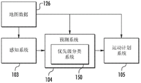
Another example aspect of the present disclosure is directed to a computing system. The computing system may include a perception system that includes one or more processors. The perception system may be configured to generate state data within each of a plurality of consecutive time frames, the state data describing at least a current state of each of a plurality of objects perceived by the autonomous vehicle. The computing system may further include a priority classification system comprising one or more processors. The priority classification system may be configured to classify each object of the plurality of objects as high priority or low priority based at least in part on the respective status data of each object within each of the plurality of consecutive time frames. The computing system may further include a prediction system comprising one or more processors. The prediction system may be configured to receive the priority classification of each respective object within each of the plurality of consecutive time frames; determining a predicted future state of each object classified as high priority within the current time frame; and providing the predicted future state of each object classified as high priority within the current time frame to the one or more processor-implemented motion planning systems.
Another example aspect of the disclosure relates to an autonomous vehicle. The autonomous vehicle may include one or more processors and one or more non-transitory computer-readable media collectively storing instructions that, when executed by the one or more processors, cause the one or more processors to perform operations. The operations may include: state data is obtained that describes at least a current or past state of a plurality of objects perceived by the autonomous vehicle. The operations may further include: determining a priority classification for each object of the plurality of objects based at least in part on the respective status data for each object. The operations may further comprise: determining an order in which the computing system determines a predicted future state for each object based at least in part on the priority classification for each object. The operations may further comprise: determining the predicted future state of each object based at least in part on the determined order.
Other aspects of the disclosure relate to various systems, apparatuses, non-transitory computer-readable media, user interfaces, and electronic devices.
These and other features, aspects, and advantages of various embodiments of the present disclosure will become better understood with reference to the following description and appended claims. The accompanying drawings, which are incorporated in and constitute a part of this specification, illustrate exemplary embodiments of the disclosure and together with the description, serve to explain the relevant principles.
Drawings
A detailed discussion of embodiments directed to one of ordinary skill in the art is set forth in the specification, which makes reference to the appended drawings, in which:
FIG. 1 depicts a block diagram of an example autonomous vehicle, according to an example aspect of the present disclosure;
FIG. 2 depicts an example perception system according to an example aspect of the present disclosure;
FIG. 3 depicts an example prediction system according to an example aspect of the present disclosure;
FIG. 4 depicts a block diagram of an example object prediction process, in accordance with an example aspect of the present disclosure;
FIG. 5 depicts a block diagram of an example computing system, according to an example aspect of the present disclosure; and
fig. 6 depicts a flowchart of an example method for determining a movement plan of an autonomous vehicle, according to an example aspect of the disclosure.
Detailed Description
In general, the present disclosure relates to systems and methods for determining priority classifications of autonomous vehicle-perceived objects and predicting future locations of objects based, at least in part, on each object's respective priority classification. In particular, the autonomous vehicle may incorporate or otherwise use a prediction system to predict a future location of an object, such as, for example, other vehicles, pedestrians, cyclists, based at least in part on perceptual information describing the current and/or past state and/or surroundings of the object. In some implementations, the autonomous vehicle can include or otherwise use a priority classification system to classify the respective priority of each object perceived by the perception system. For example, in some implementations, each object may be classified as high-priority or low-priority. The prediction system may determine a predicted future state of each object based at least in part on the priority classification of each object. For example, in some implementations, the order in which the computing system determines the predicted future state of each object may be determined based on the priority classification of each object, such as, for example, by determining the predicted future state of an object classified as high priority before determining the predicted future state of an object classified as low priority.
As one example, in a system that operates iteratively over multiple time frames, the prediction system may determine, in a current time frame, a predicted future state of each object classified as high priority within the current time frame. However, the prediction system may wait and determine (e.g., within a subsequent time frame, or at least after providing the predicted future state of each object classified as high priority to the motion planning system) the predicted future state of each object classified as low priority within the current time frame. In this manner, the predicted future state of the high priority object may be communicated to the movement planning system in an early manner (e.g., "ahead of schedule"), thereby allowing the movement planning system additional time to determine a movement plan relative to the high priority object and allowing the vehicle to have additional time to implement the determined movement plan. In this way, the autonomous vehicle may be controlled to react faster relative to objects classified as high priority. For example, the additional time gained by predicting future states ahead by the prediction system may allow the vehicle to stop faster or otherwise make handling improvements, thereby improving passenger and vehicle safety.
According to another aspect of the disclosure, in some implementations, the type of prediction system used to determine the predicted future state of each object may be determined based on the priority classification of each object. For example, in some implementations, a high fidelity prediction system may be used for objects classified as high priority, while a low fidelity prediction system may be used for objects classified as low priority.
In accordance with another aspect of the disclosure, the priority classification system described herein may include or utilize one or more machine learned models that facilitate classification of each object perceived by the autonomous vehicle. As an example, in some implementations, the priority classification system can include a machine learned object classifier configured to classify each perceived object, such as by classifying each object as high-priority or low-priority. Using machine learned models can improve the speed, quality and/or accuracy of object priority classification. By increasing the ability to classify objects according to priority, predictive system resources may be more efficiently used by, for example, allowing the future state of higher priority objects to be predicted before lower priority objects. Further, this may allow predicted future states of higher priority objects to be provided to the motion planning system more quickly, which reduces the overall delay for determining the motion plan, thereby reducing the response time of the autonomous vehicle and improving passenger safety and vehicle efficiency.
More particularly, in some implementations, the autonomous vehicle may contain a computing system that assists in controlling the autonomous vehicle. The autonomous vehicle may be a land-based autonomous vehicle (e.g., an automobile, truck, bus, etc.), a space-based autonomous vehicle (e.g., an airplane, drone, helicopter, or other airplane), or other type of vehicle (e.g., a boat). In some implementations, the computing system may include a perception system, a prediction system, and a motion planning system that cooperate to perceive the surroundings of the autonomous vehicle and determine a motion plan for controlling motion of the autonomous vehicle accordingly. For example, a perception system may perceive one or more objects proximate to an autonomous vehicle and provide status data indicative of the one or more objects to a prediction system. The prediction system may then determine a predicted future state of each object as perceived by the perception system. The motion planning system may then determine a motion plan for the autonomous vehicle based on the predicted future state of the object. In this manner, an autonomous vehicle may perceive objects proximate to the autonomous vehicle and, in response, control the autonomous vehicle accordingly.
In some implementations, the autonomous vehicle may perform each of the sensing, predicting, and movement planning steps sequentially using data obtained over a plurality of consecutive time frames. For example, for time frame N, the sensing system may receive sensor data for time frame N; the perception system may simultaneously generate and provide data to the prediction system for one or more objects perceived by the perception system within time frame N-1; the prediction system may simultaneously determine a predicted future state of each object perceived by the perception system within time frame N-2; and the motion planning system may use the predicted future state within time frame N-3 while determining the motion plan for the autonomous vehicle. Accordingly, a movement plan for the autonomous vehicle may be iteratively determined using data from each of the plurality of consecutive time frames.
However, in such implementations, each of the perception system, the prediction system, and the movement planning system may require the previous system to complete a respective analysis of the time-frame data before each system may subsequently analyze the time-frame data. For example, for each successive time frame, the perception system may need to complete an analysis of data obtained from one or more sensors on the autonomous vehicle in order to generate state data for use by the prediction system. Similarly, before the motion planning system may determine a motion plan for the autonomous vehicle, the prediction system may need to complete an analysis of the state data for a certain time frame in order to determine a predicted future state for each object. Thus, the total time from when a sensor senses an object until a motion plan is determined in response to the object may depend on each system completing a respective analysis of the object and all other objects sensed simultaneously with the object.
In contrast, systems and methods according to example aspects of the present disclosure may allow for determination of priority classifications for autonomous vehicle-aware objects, and determination of a predicted future state for each object based at least in part on the priority classification of each object, thereby enabling analysis of higher priority objects before lower priority objects are analyzed.
In particular, in some implementations, the sensing system may receive sensor data from one or more sensors coupled to or otherwise included in the autonomous vehicle. As examples, the one or more sensors may include a light detection and ranging (LIDAR) system, a radio detection and ranging (RADAR) system, one or more cameras (e.g., visible spectrum cameras, infrared cameras, etc.), and/or other sensors. The sensor data may contain information describing the position of the object in the surroundings of the autonomous vehicle. In some implementations, the sensor data may be obtained at multiple consecutive time frames. Based on sensor data and/or map data received from the one or more sensors, the perception system may identify one or more objects proximate to the autonomous vehicle at each time frame. As an example, in some implementations, the perception system may segment sensor data (e.g., LIDAR data) into discrete object polygons and/or track objects on a frame-by-frame (e.g., in an iterative manner over several consecutive time frames or periods).
In particular, in some implementations, the perception system may generate, for each object, state data describing the current state of the object (also referred to as one or more features of the object). As an example, the state data for each object may describe an estimation of the following object characteristics: position (also referred to as orientation); speed (also referred to as velocity); acceleration; a course; yaw rate; positioning a bit; size/footprint (e.g., in a bounding polygon or other shape); type/category (e.g., vehicle, pedestrian, bicycle); distance from the autonomous vehicle; a minimum path of interaction with the autonomous vehicle; a minimum duration of interaction with the autonomous vehicle; and/or other state information and/or the above-described forms of covariance of the state information. In some implementations, certain state data of an object may be used to determine one or more other characteristics of the object. For example, in some implementations, the position, velocity, acceleration, and/or heading of the object may be used to determine a minimum path of interaction with the autonomous vehicle or a minimum duration of interaction with the autonomous vehicle. The perception system may provide the state data to a priority classification system and/or a prediction system (e.g., in an iterative manner for each time frame).
According to an aspect of the disclosure, the autonomous vehicle may further include a priority classification system configured to classify each object perceived by the autonomous vehicle. In some implementations, the priority classification system may be included in or otherwise incorporated into the perception system. In some implementations, the priority classification system may be included in or otherwise incorporated into the prediction system. The priority classification system may classify the objects perceived by the perception system based on the state data of each object. For example, the priority classification system may classify each object into one of a plurality of priority categories and/or rank each object relative to each other object. A relative priority classification and/or ranking of each object may be determined based on the status data of each object. The priority classification of each object may indicate the importance of the object to determine a movement plan for the autonomous vehicle. As an example, the priority classification assigned to each object may be based on a number of factors, such as the likelihood of the object interacting with the autonomous vehicle, how long the object may interact with the autonomous vehicle, whether the object may affect the movement plan of the autonomous vehicle, and so forth. For example, a vehicle traveling toward an autonomous vehicle at high speed may be classified as a higher priority object than a vehicle traveling away from the autonomous vehicle.
In some implementations, the priority classification can be based on one or more heuristic procedures. For example, one or more thresholds may be used to classify an object based on one or more characteristics of the object. For example, the objects may be classified based on their distance to the autonomous vehicle or how long the objects will likely interact with the autonomous vehicle using a minimum duration, a minimum path, or a minimum distance to interact with the autonomous vehicle. Similarly, the heading and/or the velocity may be used to classify the object. For example, an object traveling on a heading away from the autonomous vehicle may be classified as a lower priority than an object traveling toward the autonomous vehicle; while objects traveling at a higher speed toward the autonomous vehicle may be classified as higher priority than objects traveling at a lower speed toward the autonomous vehicle. Other features may also be used, such as object type (e.g., vehicle, bicycle, pedestrian, etc.), object size, orientation, or any other feature described herein.
In some implementations, each object may be classified as high priority or low priority. For example, the priority classification system may classify each object as high-priority or low-priority based on its respective state data. In some implementations, the predicted future state of each high priority object may be determined before the predicted future state of any low priority object is determined.
In some implementations, a ratio of high priority objects to low priority objects may be determined based at least in part on a velocity of the autonomous vehicle. For example, in some implementations, to reduce the overall delay for determining a movement plan at a higher speed, fewer objects may be classified as high priority than at a lower speed. For example, a ratio of high priority objects to low priority objects may be determined based on the velocity of the autonomous vehicle using one or more thresholds or ranges. Each object may then be classified as either high-priority or low-priority based on the ratio of high-priority objects to low-priority objects.
In accordance with another aspect of the present disclosure, the priority classification systems and methods described herein may include or utilize one or more machine learned models that facilitate object classification. As an example, in some implementations, the priority classification system may incorporate a machine learned object priority classifier to classify each object perceived by the autonomous vehicle. In some implementations, the machine learned object priority classifier can classify each object as high priority or low priority.
According to yet another aspect of the present disclosure, machine learned models included in or employed by the priority classification systems described herein may be trained using log data collected during actual operation of autonomous vehicles on a roadway (e.g., a road). For example, the log data may contain sensor data and/or status data for various objects perceived by the autonomous vehicle (e.g., a perception system of the autonomous vehicle), as well as a final future status for each object that occurs after and/or while the sensor data is collected and/or the status data is generated. Thus, the log data may contain a large number of real-world examples of the object paired with data (e.g., sensor data, map data, perception data, etc.) collected and/or generated by the autonomous vehicle concurrent with the perception, such as whether the object becomes more or less likely to interact with the autonomous vehicle in its final future state. Training the machine learned model in terms of such real-world log data may enable the machine learned model to determine object classifications that better reflect or simulate real-world object behavior.
According to other aspects of the disclosure, the prediction system is capable of determining a predicted future state of each object based at least in part on the priority classification of each object. For example, the order in which the prediction system determines the predicted future state of each object may be based at least in part on the priority classification assigned to the objects. For example, in some implementations, the predicted future state of a higher priority object may be determined before the predicted future state of a lower priority object is determined. In some implementations, the predicted future state of each object classified as high priority may be determined before determining the predicted future state of any object classified as low priority. In some implementations, the predicted future state of each object may be determined based on the relative priority of the object compared to each other object. For example, each object perceived by the autonomous vehicle may be assigned a relative priority ranking (e.g., a ranking of 1 to Y for Y objects), and the predicted future state may be determined based on the priority rankings of the objects.
The prediction system may predict the future location of the object based at least in part on the perception information (e.g., state data for each object) received from the perception system, map data, sensor data, and/or any other data describing past and/or current states of the object, the autonomous vehicle, the surrounding environment, and/or relationships therebetween. For example, the prediction system may estimate future movement of the actor or other object over a planned interval that corresponds to a time period during which a movement plan for the autonomous vehicle is generated. In some implementations, the prediction system may append a probability likelihood to each predicted motion or other future position of the object.
In some implementations, the prediction system may receive a priority classification of each respective object as perceived by the autonomous vehicle and respective state data for each object over a plurality of consecutive time frames. For example, the perception system may provide status data for a plurality of objects over a plurality of consecutive time frames, and the priority classification system may provide a respective priority classification for each object over each of the plurality of consecutive time frames.
In some implementations, upon receiving priority classifications and corresponding state data for a plurality of objects at a current (i.e., most recently obtained) time frame, the prediction system may determine a predicted future state of each object classified as high priority at the current time frame. As used herein, the term "current" or "most recently obtained," when used with respect to a time frame, refers to the time frame that was most recently provided to a particular system (e.g., perceptual system, predictive system). For example, using the state data of the current time frame, a predicted future position may be determined for each high priority object. Once the predicted future state of each object classified as high priority has been determined within the current time frame, the predicted future state of each object classified as high priority may be provided to the motion planning system. Thus, once the predicted future state of each high priority object has been determined, the movement plan of the autonomous vehicle may be determined.
Further, in some implementations, after the prediction system has provided the predicted future state of each object classified as high priority to the motion planning system, the prediction system may determine the predicted future state of each object classified as low priority within the current time frame. Thus, each object perceived by the autonomous vehicle may have a predicted future state determined by the prediction system within each time frame.
Additionally, in some implementations, the prediction system may provide the predicted future state of each object classified as low priority within the previous sequential time frame to the motion planning system simultaneously with the predicted future state of each object classified as low priority within the current time frame. For example, once the predicted future state of each high-priority object within the current time frame has been determined, the predicted future state of each high-priority object within the current time frame may be provided to the motion planning system along with the predicted future state of each low-priority object within the previous sequential time frame. For example, by selecting, obtaining, or otherwise using the predicted future state of each low-priority object of the previous sequential time frame, the prediction system may determine the predicted future state of each object classified as low-priority. Thus, rather than waiting until each object perceived by the autonomous vehicle has been determined to be a predicted future state within the current time frame, the entire set of predicted future states, including the current predicted future state of the high priority object and the previous sequentially predicted future states of the low priority objects, may be provided to the motion planning system as long as the prediction system determines the predicted future states of all high priority objects. This may reduce the overall delay for determining the movement plan of the vehicle, thereby shortening the response time of the autonomous vehicle and improving the safety of the passengers.
In some implementations, the prediction system may include a low fidelity prediction system and a high fidelity prediction system. As used herein, the terms "low fidelity" and "high fidelity" refer to the relative computational intensity of the algorithms used by the prediction system or corresponding prediction system. For example, in some implementations, the high fidelity prediction system may include or otherwise utilize one or more machine learned models in order to predict the future position of each object. For example, in some implementations, the prediction system may be an object-oriented prediction system that generates one or more potential objects, selects one or more most likely potential objects, and develops one or more trajectories through which the object may achieve the one or more selected objects. For example, the prediction system may comprise: a scene generation system that generates and/or scores one or more targets for an object; and a scene development system that determines one or more trajectories through which an object may achieve a goal. In some implementations, the prediction system can include a machine learned goal scoring model, a machine learned trajectory development model, and/or other machine learned models. In some implementations, a high fidelity prediction system may be used to determine a predicted future state of an object classified as high priority.
In some implementations, the low-fidelity prediction system may include one or more state forward integration models. For example, a low fidelity prediction system may predict a future state of an object by forward integrating the current state. For example, the low fidelity prediction system may use the current position, current speed, and current heading of the object to determine a predicted future position of the object over a future time period. In some implementations, a low fidelity prediction system may be used to determine a predicted future state of an object classified as low priority.
As such, systems and methods according to example aspects of the present disclosure may allow for determination of a priority classification of an autonomous vehicle-perceived object. In particular, by applying one or more heuristic processes and/or using machine learned models, the systems and methods of the present disclosure may determine a respective priority classification for each object perceived by the autonomous vehicle. An order in which the predicted future state of each object is determined may then be determined based at least on the respective priority classification of each object. The ability to classify objects according to respective priorities may allow for the concentration of computing resources on higher priority objects.
As such, one technical effect and benefit of the present disclosure is to reduce the delay for determining a predicted future location of a higher priority object that is more likely to affect the autonomous vehicle's movement plan than a low priority object. In particular, the present disclosure provides techniques that enable a computing system to determine a movement plan for an autonomous vehicle once predicted future locations of all high priority objects have been determined. Thus, the present disclosure may allow for a reduction in the time required for an autonomous vehicle to perceive an object and determine a movement plan in response to the object. Further, the present disclosure may allow for the use of a higher fidelity prediction system to determine a predicted future location of a higher priority object and a lower fidelity prediction system to determine a predicted future location of a lower priority object. This may allow for more efficient use of computing resources on the autonomous vehicle.
The present disclosure also provides other technical effects and benefits, including, for example, enhanced passenger safety. For example, systems and methods according to example aspects of the present disclosure may allow for shortening of the reaction time to determine a movement plan in response to an autonomous vehicle perceived object. This may allow the autonomous vehicle to stop faster, navigate around objects, or otherwise respond faster to objects, thereby reducing the likelihood of the autonomous vehicle colliding with an object.
Referring now to the drawings, example aspects of the disclosure will be discussed in further detail. Fig. 1 depicts a block diagram of an example autonomous vehicle 10, according to an example aspect of the present disclosure. The autonomous vehicle 10 may include one or more sensors 101, a vehicle computing system 102, and one or more vehicle controls 107. The vehicle computing system 102 may assist in controlling the autonomous vehicle 10. In particular, the vehicle computing system 102 can receive sensor data from one or more sensors 101, attempt to understand the surrounding environment by performing various processing techniques on the data collected by the sensors 101, and generate an appropriate motion path through the surrounding environment. The vehicle computing system 102 may control one or more vehicle controls 107 to operate the autonomous vehicle 10 according to the movement path.
The vehicle computing system 102 may include one or more processors 112 and memory 114. The one or more processors 112 may be any suitable processing device (e.g., processor cores, microprocessors, ASICs, FPGAs, computing devices, microcontrollers, etc.), and may be one processor or a plurality of operatively connected processors. Memory 114 may include one or more non-transitory computer-readable storage media such as RAM, ROM, EEPROM, EPROM, flash memory devices, disks, combinations thereof, and the like. The memory 114 may store data 116 and instructions 118 that may be executed by the processor 112 to cause the vehicle computing system 102 to perform operations.
As shown in fig. 1, the vehicle computing system 102 may include a perception system 103, a prediction system 104, and a movement plan system 105 that cooperate to perceive the surroundings of the autonomous vehicle 10 and determine a movement plan for controlling movement of the autonomous vehicle 10 accordingly.
In particular, in some implementations, the sensing system 103 may receive sensor data from one or more sensors 101 coupled to or otherwise included in the autonomous vehicle 10. As examples, the one or more sensors 101 may include a light detection and ranging (LIDAR) system, a radio detection and ranging (RADAR) system, one or more cameras (e.g., visible spectrum cameras, infrared cameras, etc.), and/or other sensors. The sensor data may contain information describing the location of the object in the surrounding environment of the autonomous vehicle 10.
As one example, for a LIDAR system, the sensor data may contain the locations of a plurality of points corresponding to objects that have reflected ranging laser light (e.g., in three-dimensional space relative to the LIDAR system). For example, LIDAR systems may measure distance by measuring time of flight (TOF), which requires a short laser pulse to travel from the sensor to the object and back, to calculate distance from a known speed of light.
As another example, for a RADAR system, the sensor data may contain the locations of a plurality of points corresponding to objects that have reflected ranging radio waves (e.g., in three-dimensional space relative to the RADAR system). For example, radio waves (e.g., pulsed or continuous) transmitted by the RADAR system may reflect off of the object and return to the receiver of the RADAR system, giving information about the location and velocity of the object. Thus, the RADAR system may provide useful information about the current speed of the object.
As yet another example, for one or more cameras, various processing techniques (e.g., range imaging techniques, such as, for example, structure from motion, structured light, stereo triangulation, and/or other techniques) may be performed to identify locations of a plurality of points corresponding to an object depicted in an image captured by the one or more cameras (e.g., in three-dimensional space relative to the one or more cameras). Other sensor systems may also identify the location of points corresponding to objects.
As another example, the one or more sensors 101 may include a positioning system. The positioning system may determine the current position of the vehicle 10. The positioning system may be any device or circuitry for analyzing the orientation of the vehicle 10. For example, the positioning system may determine the position by using one or more inertial sensors, a satellite positioning system, based on IP addresses, by using triangulation and/or proximity to network access points or other network components (e.g., cell towers, WiFi access points), and/or using other techniques. The orientation of the vehicle 10 may be used by various systems of the vehicle computing system 102.
Accordingly, one or more sensors 101 may be used to collect sensor data that includes information describing the location of points (e.g., in three-dimensional space relative to the autonomous vehicle 10) corresponding to objects in the surrounding environment of the autonomous vehicle 10. In some implementations, the sensors 101 may be located at various different locations on the autonomous vehicle 10. As an example, in some implementations, one or more cameras and/or LIDAR sensors may be located in a pod or other structure mounted on top of the autonomous vehicle 10, while one or more RADAR sensors may be located inside or behind a front and/or rear bumper or body panel of the autonomous vehicle 10. As another example, the camera may also be located at the front or rear bumper of the vehicle 10. Other locations may also be used.
In addition to the sensor data, the perception system 103 may retrieve or otherwise obtain map data 126 that provides detailed information about the surroundings of the autonomous vehicle 10. The map data 126 may provide information about: the identification and location of different driving lanes (e.g., roads), road segments, buildings, or other objects or objects (e.g., lampposts, crosswalks, curbs, etc.); the location and direction of a travel lane (e.g., the location and direction of a stop, turn, bike, or other lane within a particular road or other travel lane); traffic control data (e.g., the location and description of signs, traffic lights, or other traffic control devices); and/or any other map data that provides information that assists the vehicle computing system 102 in understanding and perceiving its surroundings and their relationships.
The sensing system 103 may identify one or more objects proximate the autonomous vehicle 10 based on sensor data and/or map data 126 received from the one or more sensors 101. In particular, in some implementations, the perception system 103 may determine, for each object, state data describing the current state of the object (also referred to as a feature of the object). As an example, the state data for each object may describe an estimation of the following object characteristics: current position (also referred to as bearing); current speed (also referred to as velocity); a current acceleration; a current course; current positioning; size/shape/footprint (e.g., represented in a boundary shape such as a boundary polygon or polyhedron); type/category (e.g., vehicle and pedestrian and bicycle and others); yaw rate; distance from the autonomous vehicle; a minimum path of interaction with the autonomous vehicle; a minimum duration of interaction with the autonomous vehicle; and/or other status information.
In some implementations, the perception system 103 may determine the state data for each object in multiple iterations. In particular, the perception system 103 may update the state data of each object in each iteration. Thus, the perception system 103 may detect and track objects (e.g., vehicles) proximate to the autonomous vehicle 10 over time.
The movement planning system 105 may determine a movement plan for the autonomous vehicle 10 based at least in part on the predicted one or more future locations of the object and/or the state data of the object provided by the perception system 103. In other words, given information about the current location of the object and/or the predicted future location of the approaching object, the motion planning system 105 may determine a motion plan for the autonomous vehicle 10 that provides optimal navigation of the autonomous vehicle 10 relative to the object at such location. In some implementations, the movement plan system 105 can use the one or more adjusted vehicle parameters to determine a movement plan for the autonomous vehicle, as described herein.
In some implementations, the movement plan system 105 may evaluate one or more cost functions and/or one or more reward functions for each of one or more candidate movement plans of the autonomous vehicle 10. For example, the cost function may describe a cost (e.g., a cost over time) of following a particular candidate movement plan, while the reward function may describe a reward of following the particular candidate movement plan. For example, the reward may be opposite in sign to the cost.
Thus, given information about the current location and/or predicted future location of the object, the movement planning system 105 may determine a total cost (e.g., a sum of costs and/or rewards provided by a cost function and/or reward function) to follow a particular candidate path. The movement plan system 105 may select or determine a movement plan for the autonomous vehicle 10 based at least in part on the cost function and the reward function. For example, a movement plan that minimizes the total cost may be selected or otherwise determined. The movement plan system 105 can provide the selected movement plan to a vehicle controller 106, which controls one or more vehicle controls 107 (e.g., actuators or other devices that control airflow, steering, braking, etc.) to execute the selected movement plan.
According to an example aspect of the disclosure, the vehicle computing system 102 may also include a priority classification system 150 configured to classify one or more objects perceived by the autonomous vehicle 10. For example, in some implementations, the priority classification system 150 may receive status data from the perception system 103 that describes one or more objects perceived by the autonomous vehicle 10. The priority classification system 150 may then classify each object based at least in part on its respective state data.
For example, in some implementations, the priority classification of each object may be based on the bearing, speed, and/or heading of the object. For example, objects closer to the autonomous vehicle may be given a higher priority classification. Similarly, a higher priority classification may be given to objects traveling in a direction toward the autonomous vehicle and/or toward a location at which the autonomous vehicle is about to arrive. In some implementations, objects traveling at a higher speed, such as objects traveling toward an autonomous vehicle at a higher speed, may be given a higher priority classification than objects traveling at a lower speed.
In some implementations, the priority classification may be based on a likelihood that the object will interact with the autonomous vehicle, or otherwise be of importance in determining a movement plan for the autonomous vehicle. For example, objects traveling in a direction opposite the autonomous vehicle may be given a lower priority classification than objects traveling in a direction that will interact with the motion path of the autonomous vehicle.
In some implementations, the priority classification can be based on object type. For example, in some implementations, pedestrians may be assigned a higher priority than other objects, such as static (i.e., non-moving) vehicles. Similarly, other object types and/or categories may be used to determine the priority classification of each object.
In some implementations, the priority classification of each object may be based on a minimum path of interaction with the autonomous vehicle or a minimum duration of interaction with the autonomous vehicle. For example, the minimum path of interaction with the autonomous vehicle may correspond to a distance along one or more lanes that the object will have to traverse in order to interact with the object. Thus, for example, a vehicle traveling on a highway in a direction opposite the autonomous vehicle may need to exit the highway, turn around, re-enter the highway, and overrun the autonomous vehicle in order to interact with the autonomous vehicle. In such a case, the vehicle may have a longer minimum interaction path and/or a shortest duration to interact with the autonomous vehicle. In contrast, vehicles that are proximate to intersections at travel paths that are perpendicular to the travel path of the autonomous vehicle are likely to have a shorter minimum interaction path and/or a shortest duration of interaction with the autonomous vehicle. In this case, vehicles approaching the intersection may be given a higher priority classification than vehicles traveling in the opposite direction.
In some implementations, the priority classification system 150 can classify each object as high priority or low priority. For example, each object may be classified according to a binary classification in which each object is either a high priority object or a low priority object. For example, an object having a minimum interaction path and/or a minimum duration of interaction with the autonomous vehicle that is less than a threshold may be classified as a high priority object. Similarly, objects with a minimum interaction path and/or a minimum duration of interaction exceeding a threshold may be classified as low priority objects. In some implementations, objects of a particular type (e.g., pedestrians) may always be classified as high priority objects. In some implementations, objects that have been determined to be unlikely to interact with the autonomous vehicle or objects for which a movement plan for the autonomous vehicle has been determined may be classified as low priority objects.
In some implementations, the priority classification system 150 can classify each object relative to other objects perceived by the autonomous vehicle. For example, in some implementations, each object may be assigned a relative priority with respect to each other object perceived by the autonomous vehicle. For example, each object may be assigned a relative priority ranking based on its respective priority. For example, if the autonomous vehicle perceives Y objects in its surrounding environment, each object may be assigned a relative rank according to a score of 1 to Y. As such, each object may be assigned a priority classification relative to every other object perceived by the autonomous vehicle.
In some implementations, the priority classification system 150 can classify each object based on the velocity of the autonomous vehicle. In some implementations, a ratio of high priority objects to low priority objects can be determined based on the velocity of the vehicle. For example, at higher rates, it may be preferable to limit the number of high priority objects in order to reduce and/or minimize the number of high priority objects for which the prediction system 104 must determine its predicted future state within the current time frame in order to shorten and/or minimize the delay for determining a motion plan in response to such objects. In this case, there may be fewer objects classified as high priority objects than lower rates.
In some implementations, the ratio of high priority objects to low priority objects may be determined based on one or more threshold rates. For example, for a first rate range 1 to X, a ratio of 1 high priority object to Y low priority objects may be used, and for a second rate range X to 2X, a ratio of 1 high priority object to 2Y low priority objects may be used. In other implementations, other predetermined ratios may be used. In some implementations, each object may be classified as high priority or low priority such that the ratio of high priority objects to low priority objects generally conforms to a predetermined ratio (i.e., the ratio of high priority objects to low priority objects is within a threshold variance of the predetermined ratio).
In some implementations, the machine learned model can be used to determine a priority classification for each object based on its corresponding state data. For example, in some implementations, the machine learned model may be configured to classify each object as high-priority or low-priority and provide the priority classification of each object to the prediction system 104. In some implementations, the respective state data for each object can be input into a machine learned model, and data indicative of the respective priority classification of the object can be received as an output of the machine learned model.
In some implementations, the machine learned model may be trained based at least in part on training data including annotated vehicle data logs previously collected during a previous autonomous vehicle driving phase. For example, a vehicle data log may be recorded during one or more autonomous vehicle driving phases, which may include status data of objects perceived by the autonomous vehicle. In some implementations, the vehicle data log can be annotated by a human auditor to help train the machine learned model. For example, in some implementations, an object may be marked as high priority or low priority. The machine learned model may then be trained to determine a priority classification of the object based on the training data.
According to example aspects of the present disclosure, the vehicle computing system 102 may determine the predicted future state of each object based at least in part on the priority classification of each object. For example, priority classification system 150 may be configured to provide a priority classification for each object perceived by perception system 103 to prediction system 104. The prediction system 104 may then determine a predicted future state of each object based at least in part on the priority classification of each object.
For example, in some implementations, the order in which the computing system determines the predicted future state of each object may be based at least in part on a priority classification assigned to each object. For example, in some implementations, the predicted future states of all objects classified as high priority may be determined before the predicted future states of any low priority objects are determined. In some implementations, the predicted future state of each object can be determined according to its respective priority ranking. For example, for Y objects, each object may be assigned a relative priority ranking of 1 to Y, and the predicted future state of each object may be determined based on the relative priority ranking of each object (i.e., beginning with 1 and ending with Y).
As will be discussed in more detail with respect to fig. 5, in some implementations, a future location prediction system may be selected based at least in part on the priority classification of each object. For example, in some implementations, a low fidelity prediction system may be used to determine a predicted future state of a low priority object, while a high fidelity prediction system may be used to determine a predicted future state of a high priority object.
Each of the perception system 103, the prediction system 104, the motion planning system 105, the vehicle controller 106, and the priority classification system 150 may contain computer logic for providing the desired functionality. In some implementations, each of the perception system 103, the prediction system 104, the movement planning system 105, the vehicle controller 106, and the priority classification system 150 may be implemented in hardware, firmware, and/or software that controls a general purpose processor. For example, in some implementations, each of the perception system 103, the prediction system 104, the motion planning system 105, the vehicle controller 106, and the priority classification system 150 contains program files that are stored on a storage device, loaded into memory, and executed by one or more processors. In other implementations, each of the perception system 103, the prediction system 104, the movement planning system 105, the vehicle controller 106, and the priority classification system 150 contains one or more sets of computer-executable instructions stored in a tangible computer-readable storage medium, such as a RAM hard disk or an optical or magnetic medium.
Referring now to fig. 2, a block diagram depicting an example perception system 103 in accordance with an example aspect of the present disclosure is shown. Elements that are the same as or similar to those shown in fig. 1 are designated with the same reference numerals.
As shown, in some implementations, the priority classification system 150 can be implemented as a sub-portion of the perception system 103. For example, the sensing system 103 may receive sensor data and map data 126 from one or more sensors 101 (shown in fig. 1). Perception system 103 may generate status data for each object perceived by autonomous vehicle 10, perform a priority classification for each object using priority classification system 150, and provide status data and a corresponding priority classification for each object to prediction system 104.
Referring now to fig. 3, a block diagram depicting an example prediction system 104 in accordance with an example aspect of the present disclosure is shown. Elements that are the same as or similar to those shown in fig. 1 and 2 are designated with the same reference numerals.
As shown, in some implementations, the priority classification system 150 can be implemented as a sub-portion of the prediction system 104. For example, the sensing system 103 may receive sensor data and map data 126 from one or more sensors 101 (shown in fig. 1). Perception system 103 can then provide status data indicative of one or more objects to prediction system 104. Prediction system 104 can then determine a priority classification for each object using priority classification system 150 and determine a predicted future state for each object based at least in part on the priority classification for each object. Prediction system 104 then provides the predicted future state of each subject to motion planning system 105.
Thus, as shown in fig. 1-3, the priority classification system 150 may be implemented as a standalone priority classification system 150 or as a subsystem of the perception system 103 or the prediction system 104.
Referring now to fig. 4, a diagram of an example object prediction process is shown, according to an example aspect of the present disclosure. As shown in fig. 4, in some implementations, the vehicle computing system can iteratively determine the motion plan using data obtained over multiple successive time frames. For example, each of the perception system, the prediction system, and the motion planning system shown in fig. 1-3 may simultaneously analyze data from multiple consecutive time frames. As an example, for time frame N, the sensing system may receive sensor data within time frame N; the perception system may simultaneously generate and provide data to the prediction system for one or more objects perceived by the perception system within time frame N-1; the prediction system may simultaneously determine a predicted future state of each object perceived by the perception system within time frame N-2; and the motion planning system may use the predicted future state within time frame N-3 while determining the motion plan for the autonomous vehicle. Within subsequent time frame N +1, each of the perception system, the prediction system, and the movement planning system may receive data received from the upstream system and perform a corresponding analysis thereof, thereby causing the movement planning system to determine a movement plan using the predicted future state within time frame N-2. As such, a movement plan for the autonomous vehicle may be iteratively determined using data from each of a plurality of consecutive time frames.
For example, as shown in FIG. 4, block 410 represents the analysis of data from frame N by the perception system. As shown, the analysis of the frame N data by the perception system may include a plurality of objects 411A-J. Each object may have associated state data describing the object generated by the perception system. For example, for each object 411A-J, the perception system may generate state data describing orientation, speed, acceleration, heading, size, type, yaw rate, or other state data describing the object described herein.
As indicated by the arrow from block 410 to block 430, once the perception system has completed its analysis, state data describing objects 411A-J generated by the perception system within frame N may be provided to the prediction system.
However, according to example aspects of the present disclosure, the prediction system may also receive a priority classification for each object. For example, in some implementations, each object may be classified as either high priority ("HP") or low priority ("LP"). As described herein, a priority classification for each object may be determined based on the respective state data for each object. Further, in some implementations, the priority classification may be determined by a machine learned model.
Accordingly, as shown in block 430, the prediction system may receive from the perception system a respective priority classification for each object and respective state data describing each object. The perception system may then determine a predicted future state of each object based at least in part on the respective priority classification of each object. For example, in some implementations, the prediction system may first determine a predicted future state for each object classified as high priority. For example, as shown in FIG. 4, the prediction system may first determine a predicted future state of the HP objects 431A-D. In other words, the prediction system may determine the predicted future state of each object classified as high priority based at least in part on the state data obtained within the most recent time frame (frame N).
According to further example aspects of the present disclosure, once the prediction system has determined the predicted future state of each object classified as high priority, the prediction system may provide the predicted future state of each object classified as high priority within the current time frame to the motion planning system. For example, as indicated by the arrows in dashed boxes 440 through 450, once the prediction system has determined the predicted future state of each high-priority object HP 431A-D, the prediction system may provide the predicted future states of the objects HP 431A-D to the movement planning system. As such, the movement plan system may begin determining the movement plan in an early manner (e.g., "ahead of schedule").
According to further example aspects of the present disclosure, once the prediction system has determined a predicted future state for each object classified as high priority, the prediction system may determine a predicted future state for each object identified as low priority. For example, after the prediction system has provided the high-priority subjects HP 431A-D to the motion planning system, the prediction system may determine a predicted future state of each of the low-priority subjects LP 431E-J. As such, each object perceived within a particular frame (e.g., frame N) may have a predicted future state determined by the prediction system.
In some implementations, the prediction system may be further configured to provide the predicted future state of each object classified as low priority within the previous sequential time frame to the motion planning system simultaneously with the predicted future state of each object classified as low priority within the current time frame. In other words, in some implementations, the predicted future state of the low priority object may be determined by selecting, obtaining, or otherwise determining the predicted future state of the object based on state data obtained within a previous sequential time frame.
For example, as shown in block 420, the prediction system may predetermine predicted future states of the objects 421A-J, including high priority objects HP 421A-D and low priority objects LP 421E-J. For example, when the perception system generates state data for objects 411A-J within time frame N (in block 410), the prediction system may simultaneously determine predicted future states of high-priority objects HP 421A-D and low-priority objects LP 421E-J within time frame N-1 (in block 420). Further, as an example, each high-priority object HP 421A-D may correspond to each high-priority object HP 431A-D, respectively, for timeframe N-1, and each low-priority object LP 421E-J may correspond to each low-priority object LP 431E-J, respectively, for timeframe N-1.
Thus, as indicated by the arrow from block 440 to block 450, when the prediction system provides the predicted future states of the high priority objects HP 431A-D to the motion planning system, the prediction system may be configured to simultaneously provide the previously determined predicted future states of each of the low priority objects (i.e., LP 431E-J) within the previous sequential time frame (i.e., LP 421E-J). In this way, a complete set of predicted future states, including the predicted future states of all high priority objects (HP 431A-D) within the current time frame and the previously determined predicted future states of all low priority objects (LP 421E-J) within the previous sequential time frame, may be simultaneously provided to the motion planning system as long as the prediction system has determined the predicted future state of each object (HP 431A-D) classified as high priority.
The object prediction process depicted in fig. 4 provides the advantage that the time required to determine a movement plan for an autonomous vehicle may be reduced. For example, for a vehicle autonomous system, such as the sequential vehicle autonomous systems described herein, the movement planning system may receive the predicted future state of each object more quickly, allowing the movement plan to be determined ahead of a schedule. Further, the prediction system determines a reduction in time for the predicted future state of each object, which may correspond to a ratio of high priority objects to low priority objects. For example, as shown in FIG. 4, the prediction system will only need to determine the predicted future state of the high-priority objects HP 431A-D (i.e., 4 of the 10 objects) within the time frame N before providing the predicted future state of each object 431A-D and 421E to the motion planning system, which may reduce the required processing time by approximately 60%.
Further, because low priority objects may be classified based on their negligible impact on the movement plan, using the predicted future state of the low priority objects at the previous sequential time frame may net increase the safety of passengers and autonomous vehicles. For example, low priority objects, such as objects located away from the autonomous vehicle and traveling away from the autonomous vehicle, may be less likely to affect the movement plan of the autonomous vehicle. However, high priority objects, such as objects traveling toward or located near the autonomous vehicle, are likely to affect the movement plan of the autonomous vehicle. By having such high priority objects sensed by the sensors, sensed by the sensing system, predicted by the prediction system, and planned by the movement planning system in a reduced time, the autonomous vehicle may respond more quickly to the high priority objects, thereby reducing the likelihood of unsafe conditions such as collisions.
Referring now to fig. 5, a block diagram of an example computing system 100 is depicted, in accordance with an example embodiment of the present disclosure. Elements that are the same as or similar to those shown in fig. 1-3 are identified with the same reference numerals. As shown, the example computing system 100 may include a computing system 102 (e.g., a vehicle computing system 102 on an autonomous vehicle 10) and a machine learning computing system 130, both communicatively coupled by one or more communication networks 180.
The computing system 102 may include one or more processors 112 and memory 114. The one or more processors 112 may be any suitable processing device (e.g., processor core, microprocessor, ASIC, FPGA, controller, microcontroller, etc.) and may be one processor or multiple operatively connected processors. The memory 114 may include one or more non-transitory computer-readable storage media, such as RAM, ROM, EEPROM, EPROM, one or more memory devices, flash memory devices, etc., and combinations thereof.
The memory 114 may store information that can be accessed by the one or more processors 112. For example, the memory 114 (e.g., one or more non-transitory computer-readable storage media, storage devices) may store data 116 that can be obtained, received, accessed, written, manipulated, created, and/or stored. The memory 114 may also store computer readable instructions 118 that are executable by the one or more processors 112. The instructions may be software written in any suitable programming language, or may be implemented in hardware. Additionally or alternatively, the instructions may be executed in logical and/or virtual separate threads on the processor 112. For example, the memory 114 may store instructions that, when executed by the one or more processors 112, cause the one or more processors 112 to perform any of the operations and/or functions described herein.
As described herein, the computing system 102 may also include a perception system 103, a prediction system 104, a motion planning system 105, a vehicle controller 106, and a priority classification system 150. Each of the perception system 103, the prediction system 104, the motion planning system 105, the vehicle controller 106, and the priority classification system 150 may contain computer logic for providing the desired functionality. In some implementations, each of the perception system 103, the prediction system 104, the movement planning system 105, the vehicle controller 106, and the priority classification system 150 may be implemented in hardware, firmware, and/or software that controls a general purpose processor. For example, in some implementations, each of the perception system 103, the prediction system 104, the motion planning system 105, the vehicle controller 106, and the priority classification system 150 may contain program files that are stored on a storage device, loaded into memory, and executed by one or more processors. In other implementations, each of the perception system 103, the prediction system 104, the movement planning system 105, the vehicle controller 106, and the priority classification system 150 may contain one or more sets of computer-executable instructions stored in a tangible computer-readable storage medium, such as a RAM hard disk or an optical or magnetic medium.
According to example aspects of the present disclosure, in some implementations, the prediction system 104 may include a low fidelity prediction system 122 and a high fidelity prediction system 124. For example, in some implementations, the high fidelity prediction system 124 may include or otherwise utilize one or more machine learned models in order to predict the future position of each object. For example, in some implementations, the high fidelity prediction system 124 may be an object-oriented prediction system that generates one or more potential objects, selects one or more most likely potential objects, and develops one or more trajectories through which an object may achieve the one or more selected objects. For example, the high fidelity prediction system 124 may comprise: a scene generation system that generates and/or scores one or more targets for an object; and a scene development system that determines one or more trajectories through which an object may achieve a goal. In some implementations, the high fidelity prediction system 124 can include machine learned target scoring models, machine learned trajectory development models, and/or other machine learned models.
In some implementations, the low fidelity prediction system 122 may include one or more state forward integration models. For example, low fidelity prediction system 122 may predict a future state of the object by forward integrating the current state. For example, the low fidelity prediction system may use the current position, current speed, and current heading of the object to determine a predicted future position of the object over a future time period.
In some implementations, by selecting a future location prediction system based at least in part on the priority classification of the objects, and determining a predicted future state of the objects using the selected future location prediction system, the computing system 102 can determine the predicted future state of each object based at least in part on the priority classification of the objects. For example, in some implementations, the low fidelity prediction system 122 may be used to determine a predicted future state of an object classified as low priority, while the high fidelity prediction system 124 may be used to determine a predicted future state of an object classified as high priority.
Using a low fidelity prediction system and a high fidelity prediction system to determine the predicted future state of each object based at least in part on the priority classification of each object provides the advantages of: computational resources may be allocated more efficiently. For example, a complex prediction system (such as the high fidelity prediction system 124) may not be needed to determine predicted future states of these objects, as their impact on the vehicle motion plan may be negligible and classified as low priority objects. For example, a low priority object located away from the autonomous vehicle and/or traveling in a direction away from the autonomous vehicle may have little impact on the autonomous vehicle's movement plan. As such, the granularity provided by the goal-oriented prediction system described herein provides little benefit over a low-fidelity prediction model 122 (such as a simple state forward integration model). Thus, by first determining the priority classification of each object, computing resources may be more efficiently allocated to determine the predicted future state of each object.
According to another example aspect of the disclosure, the priority classification system 150 may store or contain one or more machine learned models 120. For example, the machine learned model 120 may be or may otherwise include various machine learned models, such as a decision tree based model, a support vector machine, a k-nearest neighbor model, a neural network (e.g., a deep neural network), or other multi-layered non-linear model. Example neural networks include feed-forward neural networks, recurrent neural networks (e.g., long-short term memory recurrent neural networks), or other forms of neural networks.
In some implementations, the one or more machine learned models 120 can include a machine learned object priority classifier. For example, in some implementations, the machine learned object priority classifier can be configured to classify objects perceived by the perception system 103 as high priority or low priority. In some implementations, the machine learned object priority classifier can be configured to rank the objects according to respective object priorities, as described herein.
In some implementations, the computing system 102 can determine a priority classification for each object using the machine learned model 120. For example, computing system 102 can obtain data describing a machine learned model, input the respective state data for each object as perceived by perception system 103 into machine learned model 120, and receive data indicating the respective priority classification for each object as an output of the machine learned model. In some implementations, the machine learned model 120 and/or the priority classification system 150 can be configured to provide a respective priority classification for each object to the prediction system 104.
In some implementations, the vehicle computing system 102 can receive one or more machine learned models 120 from the machine learning computing system 130 over the network 180 and can store the one or more machine learned models 120 in the memory 114. The vehicle computing system 102 can then use or otherwise implement the one or more machine learned models 120 (e.g., by the processor 112).
In some implementations, certain operations described herein may be performed by a machine learning computing system 130 that is located remotely from the computing system 102 and that communicates with the computing system 102 over one or more wireless networks 180 (e.g., a cellular data network, a satellite communication network, a wide area network, etc.). As an example, the machine learning computing system 130 may include one or more server computing devices. Where multiple server computing devices are used, the server computing devices may be arranged according to a parallel computing architecture, a sequential computing architecture, or a combination thereof.
Machine learning computing system 130 may include one or more processors 132 and memory 134. The one or more processors 132 may be any suitable processing device (e.g., processor core, microprocessor, ASIC, FPGA, controller, microcontroller, etc.) and may be one processor or multiple operatively connected processors. Memory 134 may include one or more non-transitory computer-readable storage media, such as RAM, ROM, EEPROM, EPROM, one or more memory devices, flash memory devices, etc., and combinations thereof.
The memory 134 may store information that is accessible by the one or more processors 132. For example, the memory 134 (e.g., one or more non-transitory computer-readable storage media, storage devices) may store data 136 that can be obtained, received, accessed, written, manipulated, created, and/or stored. In some implementations, the machine learning computing system 130 can obtain the data from one or more storage devices remote from the system 130.
The memory 134 may also store computer readable instructions 138 that are executable by the one or more processors 132. The instructions 138 may be software written in any suitable programming language, or may be implemented in hardware. Additionally or alternatively, instructions 138 may be executed in logical and/or virtual separate threads on processor 132. For example, the memory 134 may store instructions 138 that, when executed by the one or more processors 132, cause the one or more processors 132 to perform any of the operations and/or functions described herein.
The machine learning computing system 130 may also include a network interface 164 for communicating with one or more systems or devices, including systems or devices located remotely from the machine learning computing system 130. Network interface 164 may include any circuitry, components, software, etc. for communicating with one or more networks (e.g., 180). In some implementations, the network interface 164 can include, for example, one or more of a communication controller, receiver, transceiver, transmitter, port, conductor, software, and/or hardware for data communication.
In some implementations, the machine learning computing system 130 includes one or more server computing devices. If the machine learning computing system 130 includes multiple server computing devices, such server computing devices may operate according to various computing architectures, including: such as a sequential computing architecture, a parallel computing architecture, or some combination thereof.
In addition to, or in the alternative to, the model 110 at the computing system 102, the machine learning computing system 130 may include one or more machine learned models 140. For example, the machine learned model 140 may be or may otherwise include various machine learned models, such as a decision tree based model, a support vector machine, a k-nearest neighbor model, a neural network (e.g., a deep neural network), or other multi-layered non-linear model. Example neural networks include feed-forward neural networks, recurrent neural networks (e.g., long-short term memory recurrent neural networks), or other forms of neural networks.
As an example, machine learning computing system 130 may communicate with computing system 102 according to a client-server relationship. For example, the machine learning computing system 130 may implement the machine learned model 140 to provide Web services to the computing system 102. For example, the Web service may provide object priority classifications to computing system 102.
Thus, the machine learned model 110 can be located and used in the computing system 102, and/or the machine learned model 140 can be located and used in the machine learning computing system 130.
In some implementations, the machine learning computing system 130 and/or the computing system 102 can train the machine learned models 110 and/or 140 by using the model trainer 160. The model trainer 160 may train the machine learned models 110 and/or 140 using one or more training or learning algorithms. One example training technique is error back-propagation. In some implementations, the model trainer 160 can perform a supervised training technique using a set of labeled training data 162. In other implementations, the model trainer 160 can perform an unsupervised training technique using a set of unlabeled training data 162. Model trainer 160 may perform a number of generalization techniques to improve the generalization capability of the trained model. Generalization techniques include weight decay, dropping, or other techniques.
In particular, the model trainer 160 may train the machine learned models 110 and/or 140 based on a set of training data 162. Training data 162 may include, for example, a vehicle data log from previously completed autonomous vehicle driving phases. The vehicle data log may include, for example, sensor data obtained by one or more sensors of the autonomous vehicle, state data describing one or more objects perceived by the perception system 103 of the autonomous vehicle, predicted future states of the objects perceived by the autonomous vehicle as determined by the prediction system 104, previous movement plans determined by the movement planning system 105, or other vehicle data described herein. In some implementations, model trainer 160 may be configured to train machine learned models 110 and/or 140 by determining whether an object perceived by the autonomous vehicle affects a motion plan of the autonomous vehicle.
According to another aspect of the disclosure, training data 162 may comprise a vehicle data log comprising object priority classification labels recorded by human reviewers that may be used to train machine-learned models 110 and/or 140. In particular, a human reviewer may review the vehicle data log and mark the object priority classifications for objects perceived by the perception system 103.
FIG. 5 illustrates one example computing system 100 that can be used to implement the present disclosure. Other computing systems may also be used. For example, in some implementations, computing system 102 may include a model trainer 160 and a training data set 162. In such implementations, the machine learned model 110 may be trained and used locally in the computing system 102. As another example, in some implementations, computing system 102 is not connected to other computing systems.
Additionally, components illustrated and/or discussed as being included in one of computing systems 102 or 130 may alternatively be included in the other of computing systems 102 or 130. Such a configuration may be implemented without departing from the scope of the present disclosure. The use of a computer-based system allows for a wide variety of possible configurations, combinations, and divisions of tasks and functions between components. Computer-implemented operations may be performed on a single component or on multiple components. The computer-implemented tasks and/or operations may be performed in a sequential or parallel manner. Data and instructions may be stored in a single memory device or in multiple memory devices.
Referring now to fig. 6, an example method (600) for determining a predicted future state of an autonomous vehicle-aware object based at least in part on a priority classification of the object is depicted in accordance with an example aspect of the present disclosure. Although fig. 6 depicts steps performed in a particular order for purposes of illustration and discussion, the methods of the present disclosure are not limited to the particular order or arrangement shown. The various steps of the method (600) may be omitted, rearranged, combined, and/or adapted in various ways without departing from the scope of the disclosure. The method (600) may be implemented by a computing system, such as a computing system comprising one or more computing devices.
In (602), the method (600) may comprise: state data describing at least current or past states of a plurality of objects perceived by the autonomous vehicle is obtained by a computing system. For example, the state data may include data describing one or more characteristics of the object (such as, for example, bearing, velocity, acceleration, heading, yaw rate, shape, size, type, distance from the autonomous vehicle, minimum path of interaction with the autonomous vehicle, minimum duration of interaction with the autonomous vehicle), any other state data described herein, or any state data describing the object perceived by the autonomous vehicle. In some implementations, the status data may be obtained from a perception system of the autonomous vehicle configured to generate the status data based on sensor data obtained from one or more sensors of the autonomous vehicle.
In (604), the method (600) may comprise: determining, by the computing system, a priority classification for each object of the plurality of objects based at least in part on the respective state data for each object. For example, in some implementations, the priority classification of each object may be determined by a priority classification system. In some implementations, the priority classification can be a high priority classification or a low priority classification for each object. In some implementations, the priority classification can be a respective priority ranking of each object (relative to each other object perceived by the autonomous vehicle).
In some implementations, the priority classification can be determined by a machine learned model. For example, in (606), the method may include obtaining data describing a machine learned model. In some implementations, data describing the machine learned model may be obtained from a memory (e.g., a non-transitory computer-readable medium) of a computing system. In some implementations, the machine learned model can be a machine learned object priority classifier configured to classify each object as high or low priority based on its respective state data.
At (608), the method (600) may include inputting the respective state data of the objects into the machine learned model. For example, state data generated by the perception system may be received by a machine learned model of the priority classification system. The respective state data for each object may be input into a machine learned model to determine a priority classification for each respective object.
In (610), the method (600) may include receiving data indicative of the respective priority classification as an output of the machine learned model. For example, in some implementations, the machine learned model can be a machine learned object priority classifier configured to classify each object as high-priority or low-priority and output a respective high-priority or low-priority classification based on the respective state data of each object.
In (612), the method (600) may comprise: determining, by the computing system, an order in which the computing system determines the predicted future state of each object based at least in part on the priority classification of each object. For example, in some implementations, each object may be classified as high-priority or low-priority, and the order may be determined such that the predicted future state of each high-priority object is determined before the predicted future state of any low-priority object is determined. In some implementations, determining the order in which the computing system determines the predicted future state of each object is based on a priority ranking assigned to each object. For example, the highest ranked object may first determine the predicted future state, while each successively ranked object is determined in turn according to each object's respective priority ranking.
In (614), the method (600) may comprise: determining, by the computing system, a predicted future state of each object based at least in part on the determined order. For example, in some implementations, the prediction system may determine an order of predicted future states of each object classified as high priority before determining predicted future states of each object classified as low priority. In some implementations, once the prediction system has determined the predicted future state of each object classified as high priority, the prediction system may be configured to provide the predicted future state of each high priority object to the motion planning system. In some implementations, determining the predicted future state of each object classified as high priority may include: a future state of each high priority object is determined based at least in part on state data obtained within the most recent time frame. In some implementations, determining the predicted future state of each object classified as low priority may include: a predicted future state of the object is determined based on state data obtained within a previous sequential time frame. For example, in some implementations, while the prediction system provides the predicted future state of each high-priority object within the current time frame to the motion planning system, the prediction system may provide the previously determined predicted future state of each low-priority object within the previous sequential time frame to the motion planning system.
In some implementations, determining the predicted future state of each object based at least in part on the determined order can include: selecting a future location prediction system based at least in part on the priority classification of the object; and determining a predicted future state of the object using the selected future location prediction system. For example, in some implementations, the prediction system may include a low fidelity prediction system and a high fidelity prediction system. In some implementations, a low fidelity prediction system may be used to determine the predicted future state of each low priority object, while a high fidelity prediction system may be used to determine the predicted future state of each high priority object.
In (616), the method (600) may comprise: determining a movement plan for the autonomous vehicle based at least in part on the predicted future state of the at least one object. For example, the movement planning system may receive one or more predicted future states of the one or more objects perceived by the autonomous vehicle, and may determine a movement plan for the autonomous vehicle based at least in part on the predicted future states of the one or more objects.
As such, systems and methods according to example aspects of the present disclosure may allow for determining a priority classification of an autonomous vehicle-aware object, determining a predicted future state of each object based on the respective priority classification of each object, and determining a movement plan of the autonomous vehicle based at least in part on the predicted future state.
The technology discussed herein relates to servers, databases, software applications, and other computer-based systems, as well as actions taken by and information to and from such systems. The inherent flexibility of computer-based systems allows for a variety of possible configurations, combinations, and divisions of tasks and functions between components. For example, the processes discussed herein may be implemented using a single device or component or multiple devices or components operating in combination. The database and application may be implemented on a single system or may be distributed across multiple systems. The distributed components may be run sequentially or in parallel.
While the present subject matter has been described in detail with respect to various specific exemplary embodiments thereof, each example is provided by way of illustration and not limitation of the present disclosure. Alterations, modifications, and equivalents of these embodiments may occur to others skilled in the art upon the understanding of the preceding description. Accordingly, the present disclosure does not preclude inclusion of such modifications, variations and/or additions to the present subject matter as would be readily apparent to one of ordinary skill in the art. For instance, features illustrated or described as part of one embodiment, can be used with another embodiment to yield a still further embodiment. Accordingly, the present disclosure is intended to cover such alternatives, modifications, and equivalents.
Claims (19)
1. A computer-implemented method, comprising:
obtaining, by a computing system comprising one or more processors, state data describing at least current or past states of a plurality of objects perceived by an autonomous vehicle;
determining, by the computing system, a priority classification for each object of the plurality of objects based at least in part on the respective state data for each object;
determining, by the computing system, an order in which the computing system determines a predicted future state for each object based at least in part on the priority classification of each object; and
determining, by the computing system, the predicted future state of each object of the plurality of objects based at least in part on the order, wherein determining the predicted future state comprises determining a predicted future state of an object having a higher priority classification before determining a predicted future state of an object having a lower priority classification.
2. The computer-implemented method of claim 1, further comprising:
determining, by the computing system, a movement plan for the autonomous vehicle based at least in part on the predicted future state of at least one of the objects.
3. The computer-implemented method of claim 1 or 2, wherein determining, by the computing system, a priority classification for each object of the plurality of objects based at least in part on the respective state data for each object comprises: classifying, by the computing system, each object as high-priority or low-priority.
4. The computer-implemented method of claim 1 or 2, wherein obtaining, by the computing system, state data describing at least current or past states of a plurality of objects perceived by the autonomous vehicle comprises: obtaining, by the computing system, state data describing current states of the plurality of objects perceived by the autonomous vehicle within a plurality of consecutive time frames.
5. The computer-implemented method of claim 4, wherein determining, by the computing system, the predicted future state of the object classified as high priority comprises: determining, by the computing system, the predicted future state of the object classified as high priority based at least in part on state data obtained within a most recent time frame.
6. The computer-implemented method of claim 4, wherein determining, by the computing system, the predicted future state of the object classified as low priority comprises: determining, by the computing system, a predicted future state of the object classified as low priority based on state data obtained within a previous sequential time frame.
7. The computer-implemented method of claim 1 or 2, wherein determining, by the computing system, a predicted future state of an object based at least in part on the priority classification of the object comprises:
selecting, by the computing system, a future location prediction system based at least in part on the priority classification of the object; and
determining, by the computing system, the predicted future state of the subject using the selected future location prediction system.
8. The computer-implemented method of claim 7, wherein the future position prediction system comprises a low fidelity prediction system or a high fidelity prediction system;
wherein the priority classification of each object comprises a high priority classification or a low priority classification;
wherein determining, by the computing system, the predicted future state of each low-priority object comprises: determining, by the computing system, the predicted future state of the subject using the low fidelity prediction system; and is
Wherein determining, by the computing system, the predicted future state of each high priority object comprises: determining, by the computing system, the predicted future state of the subject using the high fidelity prediction system.
9. The computer-implemented method of claim 1 or 2, wherein determining, by the computing system, the priority classification for each object comprises: determining, by the computing system, a ratio of a first number of objects to be classified as high priority to a second number of objects to be classified as low priority based at least in part on a velocity of the autonomous vehicle.
10. The computer-implemented method of claim 1 or 2, wherein determining, by the computing system, the priority classification for each object comprises: determining, by the computing system, the priority classification for each object based at least in part on one or more features of the object;
wherein the one or more characteristics of each object include one or more of: a position, a speed, an acceleration, a heading, a yaw rate, a shape, a size, a type, a distance from the autonomous vehicle, a minimum path of interaction with the autonomous vehicle, or a minimum duration of interaction with the autonomous vehicle.
11. The computer-implemented method of claim 1 or 2, wherein determining, by the computing system, a priority classification for each object based at least in part on the respective state data for each object comprises: determining, by the computing system, the priority classification for each object using a machine learned model.
12. The computer-implemented method of claim 11, wherein the machine learned model has been trained based at least in part on training data including annotated vehicle data logs previously collected during previous autonomous vehicle driving phases.
13. The computer-implemented method of claim 11, wherein determining, by the computing system, the priority classification for each object using the machine learned model comprises:
obtaining, by the computing system, data describing the machine learned model;
inputting, by the computing system, the respective state data for each object into the machine learned model; and
receiving, by the computing system, data indicative of a respective priority classification for each object as an output of the machine learned model.
14. The computer-implemented method of claim 1 or 2, wherein the computing system is on the autonomous vehicle.
15. A computing system, comprising:
a perception system comprising one or more processors, wherein the perception system is configured to generate state data within each of a plurality of consecutive time frames, the state data describing at least a current state of each of a plurality of objects perceived by an autonomous vehicle;
a priority classification system comprising one or more processors, wherein the priority classification system is configured to assign a priority classification to each object of the plurality of objects within each of the plurality of consecutive time frames based at least in part on the respective status data of each object; and
a prediction system comprising one or more processors, wherein the prediction system is configured to, within each of the plurality of consecutive time frames:
receiving the priority classification for each respective object;
determining a predicted future state of each object of the plurality of objects within a current time frame; and
providing the predicted future state of each object of the plurality of objects to the one or more processor-implemented motion planning systems, wherein a predicted future state of each object having a higher priority classification is provided to the motion planning system before a predicted future state of each object having a lower priority classification.
16. The computing system of claim 15, wherein the prediction system is further configured to:
providing the predicted future state of each object having a lower priority classification within a previous time frame to the motion planning system;
wherein the predicted future state of each object having a lower priority classification within the previous time frame is provided to the motion planning system concurrently with the predicted future state of each object having a higher priority classification within the current time frame.
17. The computing system of claim 15 wherein the priority classification system comprises a machine learned object priority classifier configured to classify each respective object as high priority or low priority.
18. The computing system of claim 15, wherein the prediction system is further configured to perform low fidelity prediction on objects classified as low priority; and is
Wherein the prediction system is further configured to perform high fidelity prediction on objects classified as high priority.
19. An autonomous vehicle comprising:
one or more processors; and
one or more non-transitory computer-readable media collectively storing instructions that, when executed by the one or more processors, cause the one or more processors to perform operations comprising:
obtaining status data describing at least one current or past status of a plurality of objects perceived by the autonomous vehicle;
determining a priority classification for each object of the plurality of objects based at least in part on the respective status data for each object;
determining, by the computing system, an order in which to determine a predicted future state of each object based at least in part on the priority classification of each object; and
determining the predicted future state of each object based at least in part on the determined order, wherein determining the predicted future state comprises determining a predicted future state of an object having a higher priority classification before determining a predicted future state of an object having a lower priority classification.
Applications Claiming Priority (5)
| Application Number | Priority Date | Filing Date | Title |
|---|---|---|---|
| US201762549407P | 2017-08-23 | 2017-08-23 | |
| US62/549,407 | 2017-08-23 | ||
| US15/811,865 US10216189B1 (en) | 2017-08-23 | 2017-11-14 | Systems and methods for prioritizing object prediction for autonomous vehicles |
| US15/811,865 | 2017-11-14 | ||
| PCT/US2018/047032 WO2019040349A1 (en) | 2017-08-23 | 2018-08-20 | Systems and methods for prioritizing object prediction for autonomous vehicles |
Publications (2)
| Publication Number | Publication Date |
|---|---|
| CN111133485A CN111133485A (en) | 2020-05-08 |
| CN111133485B true CN111133485B (en) | 2022-06-14 |
Family
ID=65410911
Family Applications (1)
| Application Number | Title | Priority Date | Filing Date |
|---|---|---|---|
| CN201880061470.5A Active CN111133485B (en) | 2017-08-23 | 2018-08-20 | Object prediction prioritization system and method for autonomous vehicles |
Country Status (5)
| Country | Link |
|---|---|
| US (3) | US10216189B1 (en) |
| EP (1) | EP3673470B1 (en) |
| JP (1) | JP7199421B2 (en) |
| CN (1) | CN111133485B (en) |
| WO (1) | WO2019040349A1 (en) |
Families Citing this family (66)
| Publication number | Priority date | Publication date | Assignee | Title |
|---|---|---|---|---|
| US10678244B2 (en) | 2017-03-23 | 2020-06-09 | Tesla, Inc. | Data synthesis for autonomous control systems |
| US11157441B2 (en) | 2017-07-24 | 2021-10-26 | Tesla, Inc. | Computational array microprocessor system using non-consecutive data formatting |
| US11893393B2 (en) | 2017-07-24 | 2024-02-06 | Tesla, Inc. | Computational array microprocessor system with hardware arbiter managing memory requests |
| US10671349B2 (en) | 2017-07-24 | 2020-06-02 | Tesla, Inc. | Accelerated mathematical engine |
| US11409692B2 (en) | 2017-07-24 | 2022-08-09 | Tesla, Inc. | Vector computational unit |
| US10768626B2 (en) * | 2017-09-30 | 2020-09-08 | Tusimple, Inc. | System and method for providing multiple agents for decision making, trajectory planning, and control for autonomous vehicles |
| EP3495220B1 (en) * | 2017-12-11 | 2024-04-03 | Volvo Car Corporation | Path prediction for a vehicle |
| US11760280B2 (en) | 2018-01-12 | 2023-09-19 | Uatc, Llc | Systems and methods for streaming processing for autonomous vehicles |
| US11561791B2 (en) | 2018-02-01 | 2023-01-24 | Tesla, Inc. | Vector computational unit receiving data elements in parallel from a last row of a computational array |
| US10676085B2 (en) | 2018-04-11 | 2020-06-09 | Aurora Innovation, Inc. | Training machine learning model based on training instances with: training instance input based on autonomous vehicle sensor data, and training instance output based on additional vehicle sensor data |
| US10990096B2 (en) * | 2018-04-27 | 2021-04-27 | Honda Motor Co., Ltd. | Reinforcement learning on autonomous vehicles |
| JP6988698B2 (en) * | 2018-05-31 | 2022-01-05 | トヨタ自動車株式会社 | Object recognition device |
| US11215999B2 (en) | 2018-06-20 | 2022-01-04 | Tesla, Inc. | Data pipeline and deep learning system for autonomous driving |
| US11035943B2 (en) * | 2018-07-19 | 2021-06-15 | Aptiv Technologies Limited | Radar based tracking of slow moving objects |
| US10909866B2 (en) * | 2018-07-20 | 2021-02-02 | Cybernet Systems Corp. | Autonomous transportation system and methods |
| US11361457B2 (en) | 2018-07-20 | 2022-06-14 | Tesla, Inc. | Annotation cross-labeling for autonomous control systems |
| US11636333B2 (en) | 2018-07-26 | 2023-04-25 | Tesla, Inc. | Optimizing neural network structures for embedded systems |
| US11562231B2 (en) | 2018-09-03 | 2023-01-24 | Tesla, Inc. | Neural networks for embedded devices |
| IL305330A (en) | 2018-10-11 | 2023-10-01 | Tesla Inc | Systems and methods for training machine models with augmented data |
| US11196678B2 (en) | 2018-10-25 | 2021-12-07 | Tesla, Inc. | QOS manager for system on a chip communications |
| US11403492B2 (en) | 2018-11-02 | 2022-08-02 | Aurora Operations, Inc. | Generating labeled training instances for autonomous vehicles |
| US11256263B2 (en) * | 2018-11-02 | 2022-02-22 | Aurora Operations, Inc. | Generating targeted training instances for autonomous vehicles |
| US11816585B2 (en) | 2018-12-03 | 2023-11-14 | Tesla, Inc. | Machine learning models operating at different frequencies for autonomous vehicles |
| US11537811B2 (en) | 2018-12-04 | 2022-12-27 | Tesla, Inc. | Enhanced object detection for autonomous vehicles based on field view |
| US10814870B2 (en) * | 2018-12-04 | 2020-10-27 | GM Global Technology Operations LLC | Multi-headed recurrent neural network (RNN) for multi-class trajectory predictions |
| WO2020131372A1 (en) | 2018-12-18 | 2020-06-25 | Wongpiromsarn Tichakorn | Operation of a vehicle using multiple motion constraints |
| GB2592293B (en) * | 2018-12-18 | 2022-11-30 | Motional Ad Llc | Operation of a vehicle using motion planning with machine learning |
| US11610117B2 (en) | 2018-12-27 | 2023-03-21 | Tesla, Inc. | System and method for adapting a neural network model on a hardware platform |
| US10997461B2 (en) | 2019-02-01 | 2021-05-04 | Tesla, Inc. | Generating ground truth for machine learning from time series elements |
| US11567514B2 (en) | 2019-02-11 | 2023-01-31 | Tesla, Inc. | Autonomous and user controlled vehicle summon to a target |
| US10956755B2 (en) | 2019-02-19 | 2021-03-23 | Tesla, Inc. | Estimating object properties using visual image data |
| US10741070B1 (en) * | 2019-03-04 | 2020-08-11 | GM Global Technology Operations LLC | Method to prioritize transmission of sensed objects for cooperative sensor sharing |
| US11335189B2 (en) | 2019-04-04 | 2022-05-17 | Geotab Inc. | Method for defining road networks |
| US11403938B2 (en) | 2019-04-04 | 2022-08-02 | Geotab Inc. | Method for determining traffic metrics of a road network |
| US11335191B2 (en) | 2019-04-04 | 2022-05-17 | Geotab Inc. | Intelligent telematics system for defining road networks |
| US11341846B2 (en) | 2019-04-04 | 2022-05-24 | Geotab Inc. | Traffic analytics system for defining road networks |
| US10699564B1 (en) * | 2019-04-04 | 2020-06-30 | Geotab Inc. | Method for defining intersections using machine learning |
| RU2750152C1 (en) * | 2019-04-25 | 2021-06-22 | Общество с ограниченной ответственностью "Яндекс Беспилотные Технологии" | Methods and systems for determining vehicle trajectory estimation procedure |
| US20220207883A1 (en) * | 2019-05-09 | 2022-06-30 | Sony Group Corporation | Information processing apparatus, information processing method, and program |
| US20200363800A1 (en) * | 2019-05-13 | 2020-11-19 | Great Wall Motor Company Limited | Decision Making Methods and Systems for Automated Vehicle |
| US11772643B1 (en) * | 2019-05-20 | 2023-10-03 | Zoox, Inc. | Object relevance determination |
| US11526729B2 (en) * | 2019-05-22 | 2022-12-13 | International Business Machines Corporation | Discovering higher-level actions from expert's action demonstration |
| US11643115B2 (en) * | 2019-05-31 | 2023-05-09 | Waymo Llc | Tracking vanished objects for autonomous vehicles |
| US11634162B2 (en) | 2019-08-16 | 2023-04-25 | Uatc, Llc. | Full uncertainty for motion planning in autonomous vehicles |
| US11340622B2 (en) * | 2019-08-30 | 2022-05-24 | Waymo Llc | Determining respective impacts of agents |
| DE102019213222B4 (en) * | 2019-09-02 | 2022-09-29 | Volkswagen Aktiengesellschaft | Method for predicting a future driving situation of a foreign object, device, vehicle participating in road traffic |
| US11577722B1 (en) * | 2019-09-30 | 2023-02-14 | Zoox, Inc. | Hyper planning based on object and/or region |
| DE102019216025A1 (en) * | 2019-10-17 | 2021-04-22 | Robert Bosch Gmbh | Method and control device for the automatic selection of data records for a method for machine learning |
| DE102019216074A1 (en) * | 2019-10-18 | 2021-04-22 | Robert Bosch Gmbh | Method for providing an object message about an object recognized in the surroundings of a road user in a communication network for communication with other road users |
| US11636715B2 (en) * | 2019-12-24 | 2023-04-25 | GM Cruise Holdings LLC. | Using dynamic triggers in dangerous situations to view sensor data for autonomous vehicle passengers |
| KR102193776B1 (en) * | 2019-12-26 | 2020-12-22 | 성균관대학교 산학협력단 | Reinforcement lerning based sensor data management method and system |
| KR20210114792A (en) * | 2020-03-11 | 2021-09-24 | 현대자동차주식회사 | Apparatus for tracking object based on lidar sensor and method thereof |
| EP3913551A1 (en) * | 2020-05-19 | 2021-11-24 | GEOTAB Inc. | Method for defining road networks |
| CN111814970B (en) * | 2020-06-28 | 2021-02-23 | 盾钰(上海)互联网科技有限公司 | Real-time physical engine enhanced calculation method, medium and system based on neural network |
| US11926343B2 (en) | 2020-07-20 | 2024-03-12 | Tusimple, Inc. | Classification and prioritization of objects for autonomous driving |
| CN114500736B (en) * | 2020-10-23 | 2023-12-05 | 广州汽车集团股份有限公司 | Intelligent terminal motion trail decision method and system and storage medium thereof |
| US20220169282A1 (en) * | 2020-12-01 | 2022-06-02 | Gm Cruise Holdings Llc | Autonomous vehicle high-priority data offload system |
| US11884296B2 (en) | 2020-12-21 | 2024-01-30 | Qualcomm Incorporated | Allocating processing resources to concurrently-executing neural networks |
| EP4296133A4 (en) * | 2021-03-01 | 2024-04-24 | Huawei Tech Co Ltd | Intelligent driving method and apparatus, and storage medium and computer program |
| US20220379911A1 (en) * | 2021-05-26 | 2022-12-01 | Argo AI, LLC | Using relevance of objects to assess performance of an autonomous vehicle perception system |
| DE112022002780T5 (en) * | 2021-05-26 | 2024-03-28 | Ford Global Technologies, Llc | Performance evaluation of an autonomous vehicle perception system using object relevance |
| US11884304B2 (en) * | 2021-09-08 | 2024-01-30 | Ford Global Technologies, Llc | System, method, and computer program product for trajectory scoring during an autonomous driving operation implemented with constraint independent margins to actors in the roadway |
| WO2023205444A1 (en) | 2022-04-22 | 2023-10-26 | Velo.Ai, Inc. | Artificially intelligent mobility safety system |
| JPWO2023218583A1 (en) * | 2022-05-12 | 2023-11-16 | ||
| CN116767224B (en) * | 2023-07-03 | 2024-01-23 | 小米汽车科技有限公司 | Method, device, vehicle and storage medium for determining a travelable region |
| CN116588125B (en) * | 2023-07-17 | 2023-09-19 | 四川中普盈通科技有限公司 | Vehicle-mounted edge side data processing system |
Citations (9)
| Publication number | Priority date | Publication date | Assignee | Title |
|---|---|---|---|---|
| US8767186B2 (en) * | 2007-11-07 | 2014-07-01 | Magna Electronics Inc. | Object detection system |
| JP2014157522A (en) * | 2013-02-18 | 2014-08-28 | East Nippon Expressway Co Ltd | Road traffic control system utilizing probe data |
| US9164511B1 (en) * | 2013-04-17 | 2015-10-20 | Google Inc. | Use of detected objects for image processing |
| CN105358397A (en) * | 2013-05-03 | 2016-02-24 | 谷歌公司 | Predictive reasoning for controlling speed of a vehicle |
| CN105679021A (en) * | 2016-02-02 | 2016-06-15 | 重庆云途交通科技有限公司 | Travel time fusion prediction and query method based on traffic big data |
| CN106428009A (en) * | 2015-07-31 | 2017-02-22 | 福特全球技术公司 | Vehicle trajectory determination |
| CN106504530A (en) * | 2016-10-31 | 2017-03-15 | 合肥工业大学 | A kind of user's trip route induction and managing and control system and its method |
| CN107024215A (en) * | 2016-01-29 | 2017-08-08 | 福特全球技术公司 | The object in dynamic environment is followed the trail of to improve positioning |
| CN108292356A (en) * | 2015-11-04 | 2018-07-17 | 祖克斯有限公司 | System for implementing the active safety system in autonomous vehicle |
Family Cites Families (9)
| Publication number | Priority date | Publication date | Assignee | Title |
|---|---|---|---|---|
| US8255144B2 (en) | 1997-10-22 | 2012-08-28 | Intelligent Technologies International, Inc. | Intra-vehicle information conveyance system and method |
| US9373149B2 (en) | 2006-03-17 | 2016-06-21 | Fatdoor, Inc. | Autonomous neighborhood vehicle commerce network and community |
| US9302678B2 (en) | 2006-12-29 | 2016-04-05 | Robotic Research, Llc | Robotic driving system |
| US8605947B2 (en) | 2008-04-24 | 2013-12-10 | GM Global Technology Operations LLC | Method for detecting a clear path of travel for a vehicle enhanced by object detection |
| US8917904B2 (en) * | 2008-04-24 | 2014-12-23 | GM Global Technology Operations LLC | Vehicle clear path detection |
| US8126642B2 (en) | 2008-10-24 | 2012-02-28 | Gray & Company, Inc. | Control and systems for autonomously driven vehicles |
| US9440647B1 (en) | 2014-09-22 | 2016-09-13 | Google Inc. | Safely navigating crosswalks |
| US10745003B2 (en) * | 2015-11-04 | 2020-08-18 | Zoox, Inc. | Resilient safety system for a robotic vehicle |
| WO2017120336A2 (en) * | 2016-01-05 | 2017-07-13 | Mobileye Vision Technologies Ltd. | Trained navigational system with imposed constraints |
-
2017
- 2017-11-14 US US15/811,865 patent/US10216189B1/en active Active
-
2018
- 2018-08-20 WO PCT/US2018/047032 patent/WO2019040349A1/en unknown
- 2018-08-20 JP JP2020510567A patent/JP7199421B2/en active Active
- 2018-08-20 EP EP18782225.9A patent/EP3673470B1/en active Active
- 2018-08-20 CN CN201880061470.5A patent/CN111133485B/en active Active
- 2018-12-06 US US16/211,376 patent/US11099569B2/en active Active
-
2021
- 2021-08-23 US US17/408,728 patent/US11710303B2/en active Active
Patent Citations (9)
| Publication number | Priority date | Publication date | Assignee | Title |
|---|---|---|---|---|
| US8767186B2 (en) * | 2007-11-07 | 2014-07-01 | Magna Electronics Inc. | Object detection system |
| JP2014157522A (en) * | 2013-02-18 | 2014-08-28 | East Nippon Expressway Co Ltd | Road traffic control system utilizing probe data |
| US9164511B1 (en) * | 2013-04-17 | 2015-10-20 | Google Inc. | Use of detected objects for image processing |
| CN105358397A (en) * | 2013-05-03 | 2016-02-24 | 谷歌公司 | Predictive reasoning for controlling speed of a vehicle |
| CN106428009A (en) * | 2015-07-31 | 2017-02-22 | 福特全球技术公司 | Vehicle trajectory determination |
| CN108292356A (en) * | 2015-11-04 | 2018-07-17 | 祖克斯有限公司 | System for implementing the active safety system in autonomous vehicle |
| CN107024215A (en) * | 2016-01-29 | 2017-08-08 | 福特全球技术公司 | The object in dynamic environment is followed the trail of to improve positioning |
| CN105679021A (en) * | 2016-02-02 | 2016-06-15 | 重庆云途交通科技有限公司 | Travel time fusion prediction and query method based on traffic big data |
| CN106504530A (en) * | 2016-10-31 | 2017-03-15 | 合肥工业大学 | A kind of user's trip route induction and managing and control system and its method |
Also Published As
| Publication number | Publication date |
|---|---|
| JP7199421B2 (en) | 2023-01-05 |
| US10216189B1 (en) | 2019-02-26 |
| US11710303B2 (en) | 2023-07-25 |
| US20190146507A1 (en) | 2019-05-16 |
| US20210382488A1 (en) | 2021-12-09 |
| US11099569B2 (en) | 2021-08-24 |
| EP3673470A1 (en) | 2020-07-01 |
| CN111133485A (en) | 2020-05-08 |
| JP2020531993A (en) | 2020-11-05 |
| US20190064815A1 (en) | 2019-02-28 |
| WO2019040349A1 (en) | 2019-02-28 |
| EP3673470B1 (en) | 2023-12-06 |
Similar Documents
| Publication | Publication Date | Title |
|---|---|---|
| CN111133485B (en) | Object prediction prioritization system and method for autonomous vehicles | |
| US11713006B2 (en) | Systems and methods for streaming processing for autonomous vehicles | |
| US20220171390A1 (en) | Discrete Decision Architecture for Motion Planning System of an Autonomous Vehicle | |
| US11822337B2 (en) | Autonomous vehicles featuring machine-learned yield model | |
| US11467586B2 (en) | Gridlock solver for motion planning system of an autonomous vehicle | |
| US11714417B2 (en) | Initial trajectory generator for motion planning system of autonomous vehicles | |
| US11899453B2 (en) | Systems and methods to control autonomous vehicle motion | |
| US10654453B2 (en) | Systems and methods for low-latency braking action for an autonomous vehicle | |
| US20240140487A1 (en) | Autonomous Vehicles Featuring Machine-Learned Yield Model |
Legal Events
| Date | Code | Title | Description |
|---|---|---|---|
| PB01 | Publication | ||
| PB01 | Publication | ||
| SE01 | Entry into force of request for substantive examination | ||
| SE01 | Entry into force of request for substantive examination | ||
| GR01 | Patent grant | ||
| GR01 | Patent grant | ||
| CP03 | Change of name, title or address |
Address after: Pennsylvania, USA Patentee after: Uatc Co.,Ltd. Country or region after: U.S.A. Address before: California, USA Patentee before: Uatc Co.,Ltd. Country or region before: U.S.A. |
|
| CP03 | Change of name, title or address |