CN111095851B - Techniques for signaling synchronization signal burst set patterns - Google Patents
Techniques for signaling synchronization signal burst set patterns Download PDFInfo
- Publication number
- CN111095851B CN111095851B CN201880059531.4A CN201880059531A CN111095851B CN 111095851 B CN111095851 B CN 111095851B CN 201880059531 A CN201880059531 A CN 201880059531A CN 111095851 B CN111095851 B CN 111095851B
- Authority
- CN
- China
- Prior art keywords
- burst set
- blocks
- sets
- indication
- symbols
- Prior art date
- Legal status (The legal status is an assumption and is not a legal conclusion. Google has not performed a legal analysis and makes no representation as to the accuracy of the status listed.)
- Active
Links
- 238000000034 method Methods 0.000 title claims abstract description 251
- 230000011664 signaling Effects 0.000 title description 68
- 238000004891 communication Methods 0.000 claims abstract description 220
- 238000012544 monitoring process Methods 0.000 claims description 46
- 230000002123 temporal effect Effects 0.000 claims description 14
- 238000005259 measurement Methods 0.000 claims description 4
- 230000005540 biological transmission Effects 0.000 abstract description 121
- 230000008569 process Effects 0.000 description 36
- 230000006870 function Effects 0.000 description 35
- 238000010586 diagram Methods 0.000 description 20
- 238000005516 engineering process Methods 0.000 description 20
- 238000001228 spectrum Methods 0.000 description 16
- 239000000969 carrier Substances 0.000 description 13
- 238000003491 array Methods 0.000 description 7
- 230000001360 synchronised effect Effects 0.000 description 7
- 230000002776 aggregation Effects 0.000 description 6
- 238000004220 aggregation Methods 0.000 description 6
- 230000002093 peripheral effect Effects 0.000 description 4
- 238000012545 processing Methods 0.000 description 4
- 125000004122 cyclic group Chemical group 0.000 description 3
- 230000007774 longterm Effects 0.000 description 3
- 238000007726 management method Methods 0.000 description 3
- 230000003287 optical effect Effects 0.000 description 3
- 230000008520 organization Effects 0.000 description 3
- 230000001276 controlling effect Effects 0.000 description 2
- 238000013461 design Methods 0.000 description 2
- 235000019800 disodium phosphate Nutrition 0.000 description 2
- 239000000835 fiber Substances 0.000 description 2
- 230000003993 interaction Effects 0.000 description 2
- 239000002245 particle Substances 0.000 description 2
- 230000008054 signal transmission Effects 0.000 description 2
- 241000700159 Rattus Species 0.000 description 1
- 101150096310 SIB1 gene Proteins 0.000 description 1
- 101150039363 SIB2 gene Proteins 0.000 description 1
- 238000013475 authorization Methods 0.000 description 1
- 230000006399 behavior Effects 0.000 description 1
- 230000008901 benefit Effects 0.000 description 1
- 230000001413 cellular effect Effects 0.000 description 1
- 238000004590 computer program Methods 0.000 description 1
- 238000012937 correction Methods 0.000 description 1
- 230000001066 destructive effect Effects 0.000 description 1
- 238000001514 detection method Methods 0.000 description 1
- 230000009977 dual effect Effects 0.000 description 1
- 230000007613 environmental effect Effects 0.000 description 1
- 238000001914 filtration Methods 0.000 description 1
- GVVPGTZRZFNKDS-JXMROGBWSA-N geranyl diphosphate Chemical compound CC(C)=CCC\C(C)=C\CO[P@](O)(=O)OP(O)(O)=O GVVPGTZRZFNKDS-JXMROGBWSA-N 0.000 description 1
- 238000012423 maintenance Methods 0.000 description 1
- 230000000116 mitigating effect Effects 0.000 description 1
- 238000010295 mobile communication Methods 0.000 description 1
- 238000012986 modification Methods 0.000 description 1
- 230000004048 modification Effects 0.000 description 1
- 201000003042 peeling skin syndrome Diseases 0.000 description 1
- 230000010363 phase shift Effects 0.000 description 1
- 229920001467 poly(styrenesulfonates) Polymers 0.000 description 1
- 230000001902 propagating effect Effects 0.000 description 1
- 230000001105 regulatory effect Effects 0.000 description 1
- 230000002441 reversible effect Effects 0.000 description 1
- 238000005070 sampling Methods 0.000 description 1
- 230000011218 segmentation Effects 0.000 description 1
- 230000003595 spectral effect Effects 0.000 description 1
- 230000004083 survival effect Effects 0.000 description 1
- 238000012546 transfer Methods 0.000 description 1
- 208000037918 transfusion-transmitted disease Diseases 0.000 description 1
- XLYOFNOQVPJJNP-UHFFFAOYSA-N water Substances O XLYOFNOQVPJJNP-UHFFFAOYSA-N 0.000 description 1
Images


Classifications
-
- H—ELECTRICITY
- H04—ELECTRIC COMMUNICATION TECHNIQUE
- H04J—MULTIPLEX COMMUNICATION
- H04J11/00—Orthogonal multiplex systems, e.g. using WALSH codes
- H04J11/0069—Cell search, i.e. determining cell identity [cell-ID]
-
- H—ELECTRICITY
- H04—ELECTRIC COMMUNICATION TECHNIQUE
- H04L—TRANSMISSION OF DIGITAL INFORMATION, e.g. TELEGRAPHIC COMMUNICATION
- H04L5/00—Arrangements affording multiple use of the transmission path
- H04L5/0001—Arrangements for dividing the transmission path
- H04L5/0003—Two-dimensional division
- H04L5/0005—Time-frequency
- H04L5/0007—Time-frequency the frequencies being orthogonal, e.g. OFDM(A), DMT
-
- H—ELECTRICITY
- H04—ELECTRIC COMMUNICATION TECHNIQUE
- H04L—TRANSMISSION OF DIGITAL INFORMATION, e.g. TELEGRAPHIC COMMUNICATION
- H04L5/00—Arrangements affording multiple use of the transmission path
- H04L5/003—Arrangements for allocating sub-channels of the transmission path
- H04L5/0048—Allocation of pilot signals, i.e. of signals known to the receiver
- H04L5/005—Allocation of pilot signals, i.e. of signals known to the receiver of common pilots, i.e. pilots destined for multiple users or terminals
-
- H—ELECTRICITY
- H04—ELECTRIC COMMUNICATION TECHNIQUE
- H04L—TRANSMISSION OF DIGITAL INFORMATION, e.g. TELEGRAPHIC COMMUNICATION
- H04L5/00—Arrangements affording multiple use of the transmission path
- H04L5/003—Arrangements for allocating sub-channels of the transmission path
- H04L5/0053—Allocation of signaling, i.e. of overhead other than pilot signals
-
- H—ELECTRICITY
- H04—ELECTRIC COMMUNICATION TECHNIQUE
- H04L—TRANSMISSION OF DIGITAL INFORMATION, e.g. TELEGRAPHIC COMMUNICATION
- H04L5/00—Arrangements affording multiple use of the transmission path
- H04L5/0091—Signaling for the administration of the divided path
-
- H—ELECTRICITY
- H04—ELECTRIC COMMUNICATION TECHNIQUE
- H04W—WIRELESS COMMUNICATION NETWORKS
- H04W56/00—Synchronisation arrangements
- H04W56/001—Synchronization between nodes
-
- H—ELECTRICITY
- H04—ELECTRIC COMMUNICATION TECHNIQUE
- H04W—WIRELESS COMMUNICATION NETWORKS
- H04W72/00—Local resource management
- H04W72/30—Resource management for broadcast services
-
- H—ELECTRICITY
- H04—ELECTRIC COMMUNICATION TECHNIQUE
- H04W—WIRELESS COMMUNICATION NETWORKS
- H04W74/00—Wireless channel access
- H04W74/08—Non-scheduled access, e.g. ALOHA
- H04W74/0833—Random access procedures, e.g. with 4-step access
-
- H—ELECTRICITY
- H04—ELECTRIC COMMUNICATION TECHNIQUE
- H04L—TRANSMISSION OF DIGITAL INFORMATION, e.g. TELEGRAPHIC COMMUNICATION
- H04L5/00—Arrangements affording multiple use of the transmission path
- H04L5/003—Arrangements for allocating sub-channels of the transmission path
- H04L5/0048—Allocation of pilot signals, i.e. of signals known to the receiver
- H04L5/0051—Allocation of pilot signals, i.e. of signals known to the receiver of dedicated pilots, i.e. pilots destined for a single user or terminal
Landscapes
- Engineering & Computer Science (AREA)
- Signal Processing (AREA)
- Computer Networks & Wireless Communication (AREA)
- Databases & Information Systems (AREA)
- Mobile Radio Communication Systems (AREA)
- Synchronisation In Digital Transmission Systems (AREA)
- Time-Division Multiplex Systems (AREA)
Abstract
Methods, systems, and devices for wireless communication are described that provide a Synchronization Signal (SS) burst set mode in which SS and broadcast channel transmissions may be communicated (e.g., in time). The base station may identify an SS burst set pattern that indicates, for example, a location (e.g., a time location) of an SS block transmission in a bandwidth-limited communication system. The SS burst set pattern may be determined based on a set of parameters or subcarrier spacing associated with SS and non-SS. The base station may transmit an indication of the SS burst set mode to the wireless device. A wireless device may receive an indication of an SS burst set pattern and determine one or more time locations of various SSs (e.g., Primary Synchronization Signal (PSS), Secondary Synchronization Signal (SSs), Physical Broadcast Channel (PBCH) of an SS block). The wireless device may then monitor the identified location for SSs.
Description
Cross-referencing
This patent application claims the benefit of U.S. patent application No.16/130,861 entitled "Techniques for Signaling Signal Burst Set Patterns" filed by Islam et al on 2018, 13, 9 and 62/559,623 entitled "Techniques for Signaling Signal Burst Set Patterns" filed by Islam et al, 2017, 17, 9, each of which is assigned to the assignee of the present application.
Background
The following relates generally to wireless communications, and more specifically to techniques for signaling Synchronization Signal (SS) burst set patterns.
Wireless communication systems are widely deployed to provide various types of communication content such as voice, video, packet data, messaging, broadcast, and so on. These systems may be able to support communication with multiple users by sharing the available system resources (e.g., time, frequency, and power). Examples of such multiple-access systems include fourth generation (4G) systems, such as Long Term Evolution (LTE) systems or LTE-advanced (LTE-a) systems, and fifth generation (5G) systems, which may be referred to as New Radio (NR) systems. These systems may employ various techniques, such as Code Division Multiple Access (CDMA), Time Division Multiple Access (TDMA), Frequency Division Multiple Access (FDMA), Orthogonal Frequency Division Multiple Access (OFDMA), or discrete Fourier transform spread OFDM (DFT-S-OFDM). A wireless multiple-access communication system may include several base stations or network access nodes, each supporting communication for multiple communication devices simultaneously, which may otherwise be referred to as User Equipment (UE).
Sometimes, the UE may need to perform an initial access (or initial acquisition) procedure to gain access to the wireless network. As part of the initial access procedure, the UE may need to search for a synchronization channel transmitted by a network access device (such as a base station) of the wireless network. The UE may also acquire various items of system information, such as system information contained in a Master Information Block (MIB) or one or more system information blocks (e.g., SIB1, SIB2, etc.) that may be transmitted in a Physical Broadcast Channel (PBCH) transmission from the base station. The base station may transmit SSs (e.g., Primary Synchronization Signals (PSS), Secondary Synchronization Signals (SSs), etc.) to assist the UE in connecting to and communicating with the network. These SSs may be included in certain time and frequency resources (e.g., SS blocks) that are transmitted at different times, and may also be multiplexed over frequency resources of different Radio Frequency (RF) bands. Improved techniques for scheduling and communicating SS blocks (e.g., SS burst set mode) may be desirable.
SUMMARY
The described technology relates to improved methods, systems, devices, or apparatuses that support techniques for signaling Synchronization Signal (SS) burst set patterns. In general, the described techniques provide SS blocks in which individual SS and Physical Broadcast Channel (PBCH) transmissions may be transmitted in different system operating conditions, such as different data tone or subcarrier spacing used by different sets of parameters. In some cases, PBCH transmissions may be demodulated using SS transmissions, reference signal transmissions, or a combination thereof. The PBCH transmission may be transmitted in a subset of SS block time resources (e.g., in one, two, or three symbols of an SS block). Each SS, such as a Primary Synchronization Signal (PSS) and a Secondary Synchronization Signal (SSs), may be transmitted in another subset of SS block time resources, e.g., in two or more symbols.
The SS burst set mode (or SS block set mode) may indicate a time location of an SS block. For example, the SS burst set pattern may indicate symbols, time slots, radio frame locations, etc. of the SS block (e.g., the SS burst set pattern may indicate time slots that include SS blocks, and which symbols within each time slot include SS block information). In accordance with the techniques described herein, an SS burst set pattern may be identified or determined based on a set of transmission parameters used within a wireless communication system. That is, the SS burst set pattern may depend on a set of parameters or subcarrier spacing for Synchronization (SYNC) signals and/or a set of parameters or subcarrier spacing for non-SS (e.g., such as data, uplink control, downlink control, etc.). For example, the set of SYNC parameters and the set of non-SYNC parameters may be accounted for such that the SS burst set pattern allows one or two symbols of the time slot to be reserved before the location of the SS block for downlink control, one or two symbols of the time slot to be reserved after the location of the SS block for uplink control, a guard period to be reserved between two or more SS block sets of the SS burst set pattern, and so on. Thus, the SS burst set pattern may incorporate a non-SYNC parameter set for reserving symbols for non-SSs and a SYNC parameter set for locating SS blocks.
In some cases, the base station may identify an SS burst set pattern (e.g., based on an identified subcarrier spacing of an SS and/or an identified subcarrier spacing of a non-SS). The base station may then transmit an indication of the SS burst set mode to a User Equipment (UE). For example, a base station may transmit an SS burst set mode indication via a PSS, SSS, demodulation reference signal (DMRS) of PBCH, PBCH payload, Master Information Block (MIB), System Information Block (SIB), Radio Resource Control (RRC) transmission, handover message, and/or the like. In other cases, the base station may indicate a set of parameters for the SS and non-SS, and the UE may implicitly derive the SS burst set pattern (e.g., the SS burst set pattern may be predefined or configured by the network for different sets of transmission parameters). A method of wireless communication is described.
The method can comprise the following steps: receiving an indication of an SS burst set mode; and determining a time location of one or more SSs based at least in part on the received indication.
An apparatus for wireless communication is described. The apparatus may include: means for receiving an indication of an SS burst set mode; and means for determining a time location of one or more SSs based at least in part on the received indication.
Another apparatus for wireless communication is described. The apparatus may include a processor, a memory in electronic communication with the processor, and instructions stored in the memory. The instructions are operable to cause the processor to: receiving an indication of an SS burst set mode; and determining a time location of one or more SSs based at least in part on the received indication.
A non-transitory computer-readable medium for wireless communication is described. The non-transitory computer readable medium may include instructions operable to cause a processor to: receiving an indication of an SS burst set mode; and determine a time location of the one or more SSs based at least in part on the received indication.
Some examples of the above methods, apparatus, and non-transitory computer-readable media may further include processes, features, means, or instructions for: identifying a location for monitoring one or more sets of SS blocks based at least in part on the received indication of the SS burst set pattern. Some examples of the above-described methods, apparatus, and non-transitory computer-readable media may further include processes, features, means, or instructions for monitoring the identified location for the set of one or more SS blocks.
In some examples of the above methods, apparatus, and non-transitory computer-readable media, receiving an indication of an SS burst set mode comprises: an indication of a slot occupancy pattern for a set of slots is received, the slot occupancy pattern indicating one or more slots in the set of slots that contain SS blocks in the one or more sets of SS blocks.
In some examples of the above-described methods, apparatus, and non-transitory computer-readable media, a set of SS blocks of the one or more sets of SS blocks includes a PSS symbol, a SSs symbol, one or more PBCH symbols, and one or more DMRSs of the one or more PBCH symbols.
In some examples of the above methods, apparatus, and non-transitory computer-readable media, the ordering of the set of SS symbols comprises: a PSS symbol followed by a first PBCH symbol of the one or more PBCH symbols followed by a SSS symbol followed by a second PBCH symbol of the one or more PBCH symbols followed by a third PBCH symbol of the one or more PBCH symbols.
Some examples of the above methods, apparatus, and non-transitory computer-readable media may further include processes, features, means, or instructions for: identifying a location for monitoring control information based at least in part on the received indication of the SS burst set mode.
In some examples of the above methods, apparatus, and non-transitory computer-readable media, the one or more sets of SS blocks may be monitored at a first subcarrier interval. In some examples of the above methods, apparatus, and non-transitory computer-readable media, the control information may be monitored at a second subcarrier spacing.
Some examples of the above methods, apparatus, and non-transitory computer-readable media may further include processes, features, means, or instructions for monitoring control information in the timeslot prior to the location monitored for the one or more sets of SS blocks, wherein the control information includes downlink control information.
In some examples of the above methods, apparatus, and non-transitory computer-readable media, monitoring control information in a timeslot comprises: downlink control information is monitored in one or two symbols in the time slot prior to the monitored location for the one or more sets of SS blocks.
Some examples of the above methods, apparatus, and non-transitory computer-readable media may further include processes, features, means, or instructions for: transmitting uplink control information in one or two symbols in a time slot after a position in the time slot monitored for the one or more sets of SS blocks.
Some examples of the above methods, apparatus, and non-transitory computer-readable media may further include processes, features, means, or instructions for: identifying a guard period between two of the one or more sets of SS blocks based at least in part on the received indication of the SS burst set mode.
In some examples of the above methods, apparatus, and non-transitory computer-readable media, receiving an indication of an SS burst set mode comprises: receiving a PSS, or SSS, or DMRS of PBCH, or PBCH payload, or MIB, or SIB, or RRC transmission, or handover message, or a combination thereof indicating the SS burst set pattern.
In some examples of the above methods, apparatus, and non-transitory computer-readable media, receiving an indication of an SS burst set mode comprises: an indication of a time position of each SS block within an SS burst set pattern is received.
In some examples of the above methods, apparatus, and non-transitory computer-readable media, the indication of the temporal location of each SS block comprises a symbol, or a time slot, or a radio frame location, or a combination thereof, of each SS block within the SS burst set pattern.
Some examples of the above methods, apparatus, and non-transitory computer-readable media may further include processes, features, means, or instructions for identifying a first subcarrier spacing for an SS. Some examples of the above methods, apparatus, and non-transitory computer-readable media may further include processes, features, means, or instructions for identifying the SS burst set mode based at least in part on the received indication of the SS burst set mode and the first subcarrier spacing.
Some examples of the above methods, apparatus, and non-transitory computer-readable media may further include processes, features, means, or instructions for identifying a second subcarrier spacing for a non-SS. Some examples of the above methods, apparatus, and non-transitory computer-readable media may further include processes, features, means, or instructions for identifying the SS burst set mode based at least in part on the received indication of the SS burst set mode and the second subcarrier spacing.
In some examples of the above methods, apparatus, and non-transitory computer-readable media, receiving an indication of an SS burst set mode comprises: a first indication of a first subcarrier spacing for an SS is received. Some examples of the above methods, apparatus, and non-transitory computer-readable media may further include processes, features, means, or instructions for receiving a second indication of a second subcarrier spacing for non-SSs. Some examples of the above methods, apparatus, and non-transitory computer-readable media may further include processes, features, means, or instructions for identifying an SS burst set mode based at least in part on the received first indication and the received second indication.
Some examples of the above methods, apparatus, and non-transitory computer-readable media may further include processes, features, means, or instructions for identifying an SS burst set mode based at least in part on the received indication. Some examples of the above methods, apparatus, and non-transitory computer-readable media may further include processes, features, means, or instructions for: determining a temporal location of one or more combinations of grants, or payloads of system information, or combinations thereof based at least in part on the identified SS burst set pattern.
Some examples of the above methods, apparatus, and non-transitory computer-readable media may further include processes, features, means, or instructions for identifying an SS burst set mode based at least in part on the received indication. Some examples of the above methods, apparatus, and non-transitory computer-readable media may further include processes, features, means, or instructions for: determining a time location of one or more Random Access Channel (RACH) resources based at least in part on the identified SS burst set pattern.
Some examples of the above methods, apparatus, and non-transitory computer-readable media may further include processes, features, means, or instructions for identifying an SS burst set mode based at least in part on the received indication. Some examples of the above methods, apparatus, and non-transitory computer-readable media may further include processes, features, means, or instructions for: determining a time location of a channel state information reference signal (CSI-RS), or a Measurement Reference Signal (MRS), or a combination thereof, based at least in part on the identified SS burst set pattern.
A method of wireless communication is described. The method can comprise the following steps: identifying an SS burst set pattern indicating a location of one or more SS block sets; transmitting an indication of the identified SS burst set mode; and transmitting the one or more sets of SS blocks based at least in part on the identified SS burst set pattern.
An apparatus for wireless communication is described. The apparatus may include: means for identifying an SS burst set mode indicating a location of one or more SS block sets; means for transmitting an indication of the identified SS burst set mode; and means for transmitting the one or more sets of SS blocks based at least in part on the identified SS burst set pattern.
Another apparatus for wireless communication is described. The apparatus may include a processor, a memory in electronic communication with the processor, and instructions stored in the memory. The instructions are operable to cause the processor to: identifying an SS burst set pattern indicating a location of one or more SS block sets; transmitting an indication of the identified SS burst set mode; and transmitting the one or more sets of SS blocks based at least in part on the identified SS burst set pattern.
A non-transitory computer-readable medium for wireless communication is described. The non-transitory computer readable medium may include instructions operable to cause a processor to: identifying an SS burst set pattern indicating a location of one or more SS block sets; transmitting an indication of the identified SS burst set mode; and transmitting the one or more sets of SS blocks based at least in part on the identified SS burst set pattern.
In some examples of the above methods, apparatus, and non-transitory computer-readable media, transmitting an indication of the identified SS burst set mode comprises: transmitting a PSS, or SSS, or DMRS of PBCH, or PBCH payload, or MIB, or SIB, or RRC transmission, or handover message, or a combination thereof, indicating the identified SS burst set pattern.
In some examples of the above methods, apparatus, and non-transitory computer-readable media, identifying the SS burst set mode further comprises: the temporal location of one or more sets of SS blocks within the SS burst set pattern is identified.
In some examples of the above methods, apparatus, and non-transitory computer-readable media, the time locations of the one or more sets of SS blocks within the SS burst set pattern comprise symbols, or time slots, or radio frame locations, or a combination thereof, of the respective SS blocks within the SS burst set pattern.
In some examples of the above methods, apparatus, and non-transitory computer-readable media, transmitting an indication of the identified SS burst set mode comprises: an indication of a slot occupancy pattern for a set of slots is transmitted, the slot occupancy pattern indicating one or more slots in the set of slots that contain SS blocks in the one or more sets of SS blocks.
Some examples of the above methods, apparatus, and non-transitory computer-readable media may further include processes, features, means, or instructions for identifying a first subcarrier spacing for an SS. Some examples of the above methods, apparatus, and non-transitory computer-readable media may further include processes, features, means, or instructions for identifying an SS burst set mode based at least in part on the first subcarrier spacing.
In some examples of the above methods, apparatus, and non-transitory computer-readable media, identifying the first subcarrier spacing comprises: the first subcarrier spacing is identified based at least in part on a system operating bandwidth.
Some examples of the above methods, apparatus, and non-transitory computer-readable media may further include processes, features, means, or instructions for identifying a second subcarrier spacing for the non-SS. Some examples of the above methods, apparatus, and non-transitory computer-readable media may further include processes, features, means, or instructions for identifying an SS burst set pattern based at least in part on the second subcarrier spacing.
In some examples of the above methods, apparatus, and non-transitory computer readable media, identifying the second subcarrier spacing comprises: identifying a second subcarrier spacing based at least in part on a system operating bandwidth.
In some examples of the above methods, apparatus, and non-transitory computer-readable media, transmitting an indication of the identified SS burst set mode comprises: a first indication of a first subcarrier spacing for an SS is transmitted. Some examples of the above methods, apparatus, and non-transitory computer-readable media may further include processes, features, means, or instructions for transmitting a second indication of a second subcarrier spacing for non-SSs.
In some examples of the above-described methods, apparatus, and non-transitory computer-readable media, a set of SS blocks of the one or more sets of SS blocks includes a PSS symbol, an SSs symbol, one or more PBCH symbols, and one or more DMRSs of the one or more PBCH symbols.
In some examples of the above methods, apparatus, and non-transitory computer-readable media, the ordering of the set of SS symbols comprises: a PSS symbol followed by a first PBCH symbol of the one or more PBCH symbols followed by a SSS symbol followed by a second PBCH symbol of the one or more PBCH symbols followed by a third PBCH symbol of the one or more PBCH symbols.
Some examples of the above methods, apparatus, and non-transitory computer-readable media may further include processes, features, means, or instructions for: transmitting control information in a time slot using a first subcarrier spacing based at least in part on the identified pattern of SS burst sets, wherein the one or more sets of SS blocks may be transmitted in the time slot using a second subcarrier spacing.
In some examples of the above methods, apparatus, and non-transitory computer-readable media, the control information comprises downlink control information.
Some examples of the above methods, apparatus, and non-transitory computer-readable media may further include processes, features, means, or instructions for: transmitting downlink control information in a time slot prior to transmitting the one or more sets of SS blocks in the time slot based at least in part on the identified SS burst set pattern.
In some examples of the above methods, apparatus, and non-transitory computer-readable media, transmitting downlink control information in a timeslot comprises: transmitting downlink control information in one or two symbols in a time slot before transmitting the one or more sets of SS blocks in the time slot.
Some examples of the above methods, apparatus, and non-transitory computer-readable media may further include processes, features, means, or instructions for: uplink control information is monitored in one or both symbols in a slot after transmitting the one or more sets of SS blocks in the slot.
Brief Description of Drawings
Fig. 1 illustrates an example of a system for wireless communication that supports techniques for signaling a Synchronization Signal (SS) burst set pattern in accordance with aspects of the present disclosure.
Fig. 2 illustrates an example of a wireless communication system that supports techniques for signaling SS burst set mode in accordance with aspects of the present disclosure.
Fig. 3 illustrates an example of a set of timeslots supporting a technique for signaling SS burst set mode in accordance with aspects of the present disclosure.
Fig. 4 illustrates an example of an SS burst set mode that supports techniques for signaling an SS burst set mode in accordance with aspects of the present disclosure.
Fig. 5 illustrates an example of an SS block configuration supporting techniques for signaling SS burst set mode, in accordance with aspects of the present disclosure.
Fig. 6-10 illustrate examples of SS burst set modes that support techniques for signaling SS burst set modes according to aspects of the present disclosure.
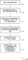
Fig. 11 illustrates an example of a process flow supporting techniques for signaling SS burst set mode in accordance with aspects of the present disclosure.
Fig. 12 illustrates an example of a process flow supporting techniques for signaling SS burst set mode in accordance with aspects of the present disclosure.
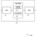
Fig. 13 through 15 show block diagrams of devices that support techniques for signaling SS burst set mode in accordance with aspects of the present disclosure.
Fig. 16 illustrates a block diagram of a system including a User Equipment (UE) supporting techniques for signaling SS burst set mode, in accordance with aspects of the present disclosure.
Fig. 17-19 show block diagrams of devices that support techniques for signaling SS burst set mode, in accordance with aspects of the present disclosure.
Fig. 20 illustrates a block diagram of a system including a base station supporting techniques for signaling SS burst set mode, in accordance with aspects of the present disclosure.
Fig. 21-25 illustrate methods of techniques for signaling SS burst set mode in accordance with aspects of the present disclosure.
Detailed Description
A wireless communication system as described herein may be configured to provide a Synchronization Signal (SS) block in which respective SS and Physical Broadcast Channel (PBCH) transmissions may be transmitted to assist a User Equipment (UE) in initial acquisition and communication with a base station. In some examples, PBCH transmissions may be transmitted in a subset of SS block time resources (e.g., in one, two, or three symbols of an SS block), while SSs (e.g., Primary Synchronization Signals (PSS) and Secondary Synchronization Signals (SSs)) may be transmitted in another subset of SS block time resources (e.g., in two symbols of an SS block). Thus, an SS block may indicate a combination of PSS, SSs, PBCH, and DMRS of PBCH signals, or a subset of these. An SS block may be transmitted in a group (which may be referred to as an SS burst set) that includes one or more SS blocks. The UE may use the SS burst set pattern to, for example, determine or find a time location of a System Information Block (SIB) resource, a Random Access Channel (RACH) resource, a channel state information reference signal (CSI-RS) resource, and/or the like. In some cases, the location or pattern of the SS blocks within a set of SS bursts may be identified for each Radio Frequency (RF) band depending on the set of SS block transmission parameters and data/control transmission parameters or other configurations for time slot or radio frame design, etc.
In some examples (e.g., a wireless communication system using two PBCH symbols per SS block), PBCH transmissions may be transmitted using a frequency bandwidth that is larger than a frequency bandwidth of SS transmissions, where one or more of the PBCH transmissions (e.g., demodulation reference signal (DMRS) transmissions) may be useful to provide reliable demodulation of the PBCH transmissions. However, some wireless communication systems may operate in a reduced bandwidth for some carrier frequencies or otherwise be constrained by the wireless communication system. In such a case, PBCH transmissions may not be communicated using a frequency bandwidth that is larger than a frequency bandwidth of SS transmissions (e.g., PBCH transmissions may be communicated using a frequency bandwidth that is consistent with a frequency bandwidth used for SS transmissions). Thus, to support PBCH payload (e.g., to convey necessary PBCH information), a wireless communication system may employ an increased number of PBCH symbols per SS block, e.g., three or more PBCH symbols. In such a scenario (e.g., a wireless communication system operating under bandwidth limitations or PBCH bandwidth constraints), SS blocks may use additional symbols and thus may be associated with different SS burst set patterns (e.g., SS block set patterns) in order to account for sufficient control signaling (e.g., the slot occupancy pattern for an SS block may be designed to account for different system requirements, such as control regions for downlink control signaling, uplink control signaling, etc.). The SS burst set mode described herein may further consider scenarios in which each SS and data or control signal may be communicated using different sets of subcarrier spacing or tone parameters.
Multiple SS burst set patterns may be defined for each carrier band. Different SS burst set patterns may indicate different slot occupancy patterns for slots containing SS blocks in a given set of slots, or different patterns for symbols containing SS block information in a slot. Different SS burst set modes may support different system operating constraints. A wireless communication system may support coexistence between different SYNC intervals (e.g., PSS, SSs, PBCH for SS blocks, DMRS for PBCH, etc.) and non-SYNC tone intervals (e.g., data, control, etc., which are not part of an SS block). For example, a wireless communication system using a sub-6 GHz operating bandwidth may support SYNC subcarrier spacing (e.g., a set of tone parameters) of 15kHz or 30kHz and non-SYNC subcarrier spacing of 15kHz, 30kHz, or 60 kHz. As another example, a wireless communication system using an operating bandwidth in excess of 6GHz may support SYNC subcarrier spacing of 120kHz or 240kHz and non-SYNC subcarrier spacing of 60kHz or 120 kHz. Further, the wireless communication system may support different slot length patterns (e.g., slots of 7 symbols, 14 symbols, etc.).
Further, the base station (e.g., the gNB) may select the SS burst set mode according to system operation constraints. The base station may then communicate the selected SS burst pattern to each UE served by the base station. A base station may convey an indication of SS burst set mode information through one or more combinations of PSS, SSS, DMRS of PBCH, PBCH payload (e.g., Master Information Block (MIB)), remaining system information (e.g., SIB-1 and SIB-2), other system information (e.g., other SIBs), Radio Resource Control (RRC) signaling, and/or handover messages. By allowing a base station to select and/or indicate an SS burst set mode to use, a wireless communication system may have increased flexibility, including greater scheduling flexibility, and the ability to operate according to a greater number of combinations of sets of parameters. Such techniques may also allow the wireless communication system to operate with reduced bandwidth or subcarrier spacing.
Aspects of the present disclosure are initially described in the context of a wireless communication system. Various SS mode configurations and examples of SS burst mode signaling schemes are described. Aspects of the present disclosure are further illustrated and described by, and with reference to, apparatus diagrams, system diagrams, and flow charts related to techniques for signaling SS burst set mode.
Fig. 1 illustrates an example of a wireless communication system 100 in accordance with various aspects of the present disclosure. The wireless communication system 100 includes base stations 105, UEs 115, and a core network 130. In some examples, the wireless communication system 100 may be a Long Term Evolution (LTE) network, an LTE-advanced (LTE-a) network, or a New Radio (NR) network. In some cases, wireless communication system 100 may support enhanced broadband communication, ultra-reliable (e.g., mission critical) communication, low latency communication, or communication with low cost and low complexity devices.
The base station 105 may communicate wirelessly with the UE 115 via one or more base station antennas. The base stations 105 described herein may include or may be referred to by those skilled in the art as base transceiver stations, radio base stations, access points, radio transceivers, node bs, evolved node bs (enbs), next generation node bs or gigabit node bs (any of which may be referred to as gnbs), home node bs, home evolved node bs, or some other suitable terminology. The wireless communication system 100 may include different types of base stations 105 (e.g., macro base stations or small cell base stations). The UEs 115 described herein may be capable of communicating with various types of base stations 105 and network equipment, including macro enbs, small cell enbs, gbbs, relay base stations, and the like.
Each base station 105 may be associated with a particular geographic coverage area 110, supporting communication with various UEs 115 in that particular geographic coverage area 110. Each base station 105 may provide communication coverage for a respective geographic coverage area 110 via a communication link 125, and the communication link 125 between the base station 105 and the UE 115 may utilize one or more carriers. The communication links 125 shown in the wireless communication system 100 may include uplink transmissions from the UEs 115 to the base stations 105 or downlink transmissions from the base stations 105 to the UEs 115. Downlink transmissions may also be referred to as forward link transmissions, and uplink transmissions may also be referred to as reverse link transmissions.
The geographic coverage area 110 of a base station 105 may be divided into sectors making up only a portion of the geographic coverage area 110, and each sector may be associated with a cell. For example, each base station 105 may provide communication coverage for a macro cell, a small cell, a hot spot, or other type of cell, or various combinations thereof. In some examples, the base stations 105 may be mobile and thus provide communication coverage for a moving geographic coverage area 110. In some examples, different geographic coverage areas 110 associated with different technologies may overlap, and the overlapping geographic coverage areas 110 associated with different technologies may be supported by the same base station 105 or different base stations 105. The wireless communication system 100 may include, for example, a heterogeneous LTE/LTE-a, or NR network in which different types of base stations 105 provide coverage for various geographic coverage areas 110.
The term "cell" refers to a logical communication entity for communicating with a base station 105 (e.g., on a carrier) and may be associated with an identifier to distinguish between neighboring cells (e.g., Physical Cell Identifier (PCID), Virtual Cell Identifier (VCID)) operating via the same or different carriers. In some examples, a carrier may support multiple cells, and different cells may be configured according to different protocol types (e.g., Machine Type Communication (MTC), narrowband internet of things (NB-IoT), enhanced mobile broadband (eMBB), or others) that may provide access for different types of devices. In some cases, the term "cell" may refer to a portion (e.g., a sector) of geographic coverage area 110 over which a logical entity operates.
Some UEs 115, such as MTC or IoT devices, may be low cost or low complexity devices and may provide automated communication between machines (e.g., via machine-to-machine (M2M) communication). M2M communication or MTC may refer to data communication techniques that allow devices to communicate with each other or with the base station 105 without human intervention. In some examples, M2M communications or MTC may include communications from devices that integrate sensors or meters to measure or capture information and relay the information to a central server or application that may utilize the information or present the information to a person interacting with the program or application. Some UEs 115 may be designed to collect information or implement automated behavior of a machine. Examples of applications for MTC devices include: smart metering, inventory monitoring, water level monitoring, equipment monitoring, healthcare monitoring, field survival monitoring, weather and geographic event monitoring, queue management and tracking, remote security sensing, physical access control, and transaction-based business charging.
Some UEs 115 may be configured to employ a reduced power consumption mode of operation, such as half-duplex communications (e.g., a mode that supports unidirectional communication via transmission or reception but does not simultaneously transmit and receive). In some examples, half-duplex communication may be performed with a reduced peak rate. Other power saving techniques for the UE 115 include entering a power saving "deep sleep" mode when not engaged in active communication, or operating on a limited bandwidth (e.g., according to narrowband communication). In some cases, the UE 115 may be designed to support critical functions (e.g., mission critical functions), and the wireless communication system 100 may be configured to provide ultra-reliable communication for these functions.
In some cases, the UE 115 may also be able to communicate directly with other UEs 115 (e.g., using peer-to-peer (P2P) or device-to-device (D2D) protocols). One or more UEs of the group of UEs 115 communicating with D2D may be within the geographic coverage area 110 of the base station 105. Other UEs 115 in such groups may be outside the geographic coverage area 110 of the base station 105 or otherwise unable to receive transmissions from the base station 105. In some cases, groups of UEs 115 communicating via D2D may utilize a one-to-many (1: M) system, where each UE 115 transmits to every other UE 115 in the group. In some cases, the base station 105 facilitates scheduling of resources for D2D communication. In other cases, D2D communication is performed between UEs 115 without involving base stations 105.
Each base station 105 may communicate with the core network 130 and with each other. For example, the base station 105 may interface with the core network 130 over a backhaul link 132 (e.g., via S1 or another interface). The base stations 105 may communicate with each other over backhaul links 134 (e.g., via X2 or other interface) either directly (e.g., directly between base stations 105) or indirectly (e.g., via core network 130).
The core network 130 may provide user authentication, access authorization, tracking, Internet Protocol (IP) connectivity, and other access, routing, or mobility functions. The core network 130 may be an Evolved Packet Core (EPC) that may include at least one Mobility Management Entity (MME), at least one serving gateway (S-GW), and at least one Packet Data Network (PDN) gateway (P-GW). The MME may manage non-access stratum (e.g., control plane) functions such as mobility, authentication, and bearer management for UEs 115 served by base stations 105 associated with the EPC. User IP packets may be communicated through the S-GW, which itself may be connected to the P-GW. The P-GW may provide IP address allocation as well as other functions. The P-GW may be connected to network operator IP services. The operator IP services may include access to the internet, intranet(s), IP Multimedia Subsystem (IMS), or Packet Switched (PS) streaming services.
At least some network devices, such as base stations 105, may include subcomponents, such as access network entities, which may be examples of Access Node Controllers (ANCs). Each access network entity may communicate with UEs 115 through a number of other access network transport entities, which may be referred to as radio heads, intelligent radio heads, or transmission/reception points (TRPs). In some configurations, the various functions of each access network entity or base station 105 may be distributed across various network devices (e.g., radio heads and access network controllers) or consolidated into a single network device (e.g., base station 105).
The wireless communication system 100 may operate using one or more frequency bands, typically in the range of 300MHz to 300 GHz. In general, the 300MHz to 3GHz region is called an Ultra High Frequency (UHF) region or a decimeter band because the wavelength is in a range from about 1 decimeter to 1 meter long. UHF waves can be blocked or redirected by building and environmental features. However, the wave may penetrate a variety of structures sufficiently for the macro cell to provide service to the UE 115 located indoors. UHF wave transmission can be associated with smaller antennas and shorter ranges (e.g., less than 100km) than transmission using smaller and longer waves of the High Frequency (HF) or Very High Frequency (VHF) portion of the spectrum below 300 MHz.
The wireless communication system 100 may also operate in the very high frequency (SHF) region using a frequency band from 3GHz to 30GHz (also referred to as a centimeter frequency band). The SHF region includes frequency bands (such as the 5GHz industrial, scientific, and medical (ISM) frequency bands) that can be opportunistically used by devices that can tolerate interference from other users.
The wireless communication system 100 may also operate in the Extremely High Frequency (EHF) region of the spectrum (e.g., from 30GHz to 300GHz), which is also referred to as the millimeter-wave band. In some examples, the wireless communication system 100 may support millimeter wave (mmW) communication between the UEs 115 and the base stations 105, and the EHF antennas of the respective devices may be even smaller and more closely spaced than UHF antennas. In some cases, this may facilitate the use of an antenna array within UE 115. However, propagation of EHF transmissions may experience even greater atmospheric attenuation and shorter ranges than SHF or UHF transmissions. The techniques disclosed herein may be employed across transmissions using one or more different frequency regions, and the use of frequency bands specified across these frequency regions may vary by country or regulatory agency.
In some cases, the wireless communication system 100 may utilize both licensed and unlicensed RF bands. For example, the wireless communication system 100 may employ Licensed Assisted Access (LAA), LTE unlicensed (LTE-U) radio access technology, or NR technology in an unlicensed band, such as the 5GHz ISM band. When operating in the unlicensed RF spectrum band, wireless devices, such as base stations 105 and UEs 115, may employ a Listen Before Talk (LBT) procedure to ensure that frequency channels are clear before transmitting data. In some cases, operation in the unlicensed band may be based on a CA configuration (e.g., LAA) in cooperation with CCs operating in the licensed band. Operations in the unlicensed spectrum may include downlink transmissions, uplink transmissions, peer-to-peer transmissions, or a combination of these. Duplexing in the unlicensed spectrum may be based on Frequency Division Duplexing (FDD), Time Division Duplexing (TDD), or a combination of the two.
In some examples, a base station 105 or UE 115 may be equipped with multiple antennas, which may be used to employ techniques such as transmit diversity, receive diversity, multiple-input multiple-output (MIMO) communications, or beamforming. For example, the wireless communication system 100 may use a transmission scheme between a transmitting device (e.g., base station 105) and a receiving device (e.g., UE 115), where the transmitting device is equipped with multiple antennas and the receiving device is equipped with one or more antennas. MIMO communication may employ multipath signal propagation to increase spectral efficiency by transmitting or receiving multiple signals through different spatial layers, which may be referred to as spatial multiplexing. For example, a transmitting device may transmit multiple signals via different antennas or different combinations of antennas. Also, the receiving device may receive multiple signals via different antennas or different combinations of antennas. Each of the multiple signals may be referred to as a separate spatial stream and may carry bits associated with the same data stream (e.g., the same codeword) or different data streams. Different spatial layers may be associated with different antenna ports for channel measurement and reporting. MIMO techniques include single-user MIMO (SU-MIMO), in which multiple spatial layers are transmitted to the same receiver device; and multi-user MIMO (MU-MIMO), in which a plurality of spatial layers are transmitted to a plurality of devices.
Beamforming, which may also be referred to as spatial filtering, directional transmission, or directional reception, is a signal processing technique that may be used at a transmitting device or a receiving device (e.g., base station 105 or UE 115) to shape or steer an antenna beam (e.g., a transmit beam or a receive beam) along a spatial path between the transmitting device and the receiving device. Beamforming may be achieved by combining signals communicated via antenna elements of an antenna array such that signals propagating in a particular orientation relative to the antenna array experience constructive interference while other signals experience destructive interference. The adjustment to the signals communicated via the antenna elements may include the transmitting or receiving device applying a particular amplitude and phase shift to the signals carried via each antenna element associated with the device. The adjustment associated with each antenna element may be defined by a set of beamforming weights associated with a particular orientation (e.g., relative to an antenna array of a transmitting device or a receiving device, or relative to some other orientation).
In one example, the base station 105 may use multiple antennas or antenna arrays for beamforming operations for directional communication with the UEs 115. For example, some signals (e.g., SSs, reference signals, beam selection signals, or other control signals) may be transmitted multiple times in different directions by the base station 105, which may include a signal being transmitted according to different sets of beamforming weights associated with different transmission directions. Transmissions in different beam directions may be used to identify beam directions (e.g., by the base station 105 or a receiving device, such as UE 115) used by the base station 105 for subsequent transmissions and/or receptions. Some signals, such as data signals associated with a particular recipient device, may be transmitted by the base station 105 in a single beam direction (e.g., a direction associated with the recipient device, such as the UE 115). In some examples, a beam direction associated with transmission along a single beam direction may be determined based at least in part on signals transmitted in different beam directions. For example, the UE 115 may receive one or more signals transmitted by the base station 105 in different directions, and the UE 115 may report an indication to the base station 105 of the signal for which it is received at the highest signal quality or other acceptable signal quality. Although the techniques are described with reference to signals transmitted by a base station 105 in one or more directions, a UE 115 may use similar techniques for transmitting signals multiple times in different directions (e.g., for identifying beam directions used by the UE 115 for subsequent transmission or reception) or for transmitting signals in a single direction (e.g., for transmitting data to a receiving device).
A receiving device (e.g., UE 115, which may be an example of a mmW receiving device) may attempt multiple receive beams when receiving various signals (such as SSs, reference signals, beam selection signals, or other control signals) from base station 105. For example, the recipient device may attempt multiple receive directions by: receiving via different antenna sub-arrays, processing received signals according to different antenna sub-arrays, receiving according to different sets of receive beamforming weights applied to signals received at multiple antenna elements of an antenna array, or processing received signals according to different sets of receive beamforming weights applied to signals received at multiple antenna elements of an antenna array, either of which may be referred to as "listening" according to different receive beams or receive directions. In some examples, the receiving device may use a single receive beam to receive along a single beam direction (e.g., when receiving a data signal). The single receive beam may be aligned in a beam direction determined based at least in part on listening from different receive beam directions (e.g., a beam direction determined to have the highest signal strength, highest signal-to-noise ratio, or other acceptable signal quality based at least in part on listening from multiple beam directions).
In some cases, the antennas of a base station 105 or UE 115 may be located within one or more antenna arrays that may support MIMO operation or transmit or receive beamforming. For example, one or more base station antennas or antenna arrays may be co-located at an antenna assembly (such as an antenna tower). In some cases, the antennas or antenna arrays associated with the base station 105 may be located at different geographic locations. The base station 105 may have an antenna array with a number of rows and columns of antenna ports that the base station 105 may use to support beamforming for communications with the UEs 115. Likewise, the UE 115 may have one or more antenna arrays that may support various MIMO or beamforming operations.
In some cases, the wireless communication system 100 may be a packet-based network operating according to a layered protocol stack. In the user plane, communication of the bearer or Packet Data Convergence Protocol (PDCP) layer may be IP-based. In some cases, the Radio Link Control (RLC) layer may perform packet segmentation and reassembly to communicate on logical channels. A Medium Access Control (MAC) layer may perform priority handling and multiplexing of logical channels into transport channels. The MAC layer may also use hybrid automatic repeat request (HARQ) to provide retransmission by the MAC layer, thereby improving link efficiency. In the control plane, the RRC protocol layer may provide for establishment, configuration, and maintenance of RRC connections of radio bearers supporting user plane data between the UE 115 and the base station 105 or core network 130. At the Physical (PHY) layer, transport channels may be mapped to physical channels.
In some cases, the UE 115 and the base station 105 may support retransmission of data to increase the likelihood that the data is successfully received. HARQ feedback is a technique that increases the likelihood that data will be correctly received on the communication link 125. HARQ may include a combination of error detection (e.g., using Cyclic Redundancy Check (CRC)), Forward Error Correction (FEC), and retransmission (e.g., automatic repeat request (ARQ)). HARQ may improve throughput of the MAC layer in poor radio conditions (e.g., signal-to-noise conditions). In some cases, a wireless device may support simultaneous slot HARQ feedback, where the device may provide HARQ feedback in a particular slot for data received in a previous symbol in that slot. In other cases, the device may provide HARQ feedback in a subsequent time slot or according to some other time interval.
The time interval in LTE or NR may be a basic unit of time (which may refer to, for example, a sampling period T) s 1/30,720,000 seconds). The time intervals of the communication resources may be organized according to radio frames each having a duration of 10 milliseconds (ms), where the frame period may be expressed as T f =307,200T s . The radio frames may be identified by System Frame Numbers (SFNs) ranging from 0 to 1023. Each frame may include 10 subframes numbered from 0 to 9, and each subframe may have a duration of 1 ms. The subframe may be further divided into two slots each having a duration of 0.5ms, and each slot may contain 6 or 7 modulation symbol periods (e.g., depending on the length of the cyclic prefix added before each symbol period). Each symbol period may include 2048 sample periods, excluding the cyclic prefix. In some cases, a subframe may be the smallest scheduling unit of the wireless communication system 100 and may be referred to as a Transmission Time Interval (TTI). In other cases, the minimum scheduling unit of the wireless communication system 100 may be shorter than a subframe or may be dynamically selected (e.g., in bursts of shortened ttis (sTTI) or in selected component carriers using sTTI).
In some wireless communication systems, a slot may be further divided into a plurality of mini-slots containing one or more symbols. In some examples, a symbol of a mini-slot or a mini-slot may be a minimum scheduling unit. For example, each symbol may vary in duration depending on the subcarrier spacing or operating frequency band. Further, some wireless communication systems may implement timeslot aggregation, where multiple timeslots or mini-timeslots are aggregated together and used for communication between the UE 115 and the base station 105.
The term "carrier" refers to a set of RF spectrum resources having a defined physical layer structure for supporting communications over the communication link 125. For example, the carrier of the communication link 125 may include a portion of an RF spectrum band operating according to a physical layer channel for a given radio access technology. Each physical layer channel may carry user data, control information, or other signaling. The carriers may be associated with predefined frequency channels (e.g., E-UTRA absolute radio frequency channel numbers (EARFCNs)) and may be located according to a channel grid for discovery by UEs 115. The carriers may be downlink or uplink (e.g., in FDD mode), or may be configured to carry downlink and uplink communications (e.g., in TDD mode). In some examples, a signal waveform transmitted on a carrier may include multiple subcarriers (e.g., using a multi-carrier modulation (MCM) technique, such as OFDM or DFT-s-OFDM).
The organization of carriers may be different for different radio access technologies (e.g., LTE-A, NR, etc.). For example, communications on a carrier may be organized according to TTIs or slots, each of which may include user data as well as control information or signaling supporting decoding of the user data. The carriers may also include dedicated acquisition signaling (e.g., SS or system information, etc.) and control signaling to coordinate carrier operation. In some examples (e.g., in a carrier aggregation configuration), a carrier may also have acquisition signaling or control signaling that coordinates the operation of other carriers.
The physical channels may be multiplexed on the carriers according to various techniques. The physical control channels and physical data channels may be multiplexed on the downlink carrier using, for example, Time Division Multiplexing (TDM) techniques, Frequency Division Multiplexing (FDM) techniques, or hybrid TDM-FDM techniques. In some examples, control information transmitted in the physical control channel may be distributed in a cascaded manner between different control regions (e.g., between a common control region or common search space and one or more UE-specific control regions or UE-specific search spaces).
A carrier may be associated with a particular bandwidth of the RF spectrum, and in some examples, this carrier bandwidth may be referred to as a carrier or "system bandwidth" of the wireless communication system 100. For example, the carrier bandwidth may be one of several predetermined bandwidths (e.g., 1.4, 3, 5, 10, 15, 20, 40, or 80MHz) of a carrier of a particular radio access technology. In some examples, each served UE 115 may be configured to operate over part or all of the carrier bandwidth. In other examples, some UEs 115 may be configured for operation using a narrowband protocol type associated with a predefined portion or range within a carrier (e.g., a set of subcarriers or RBs) (e.g., "in-band" deployment of narrowband protocol types).
In a system employing MCM technology, a resource element may include one symbol period (e.g., the duration of one modulation symbol) and one subcarrier, where the symbol period and subcarrier spacing are inversely related. The number of bits carried by each resource element may depend on the modulation scheme (e.g., the order of the modulation scheme). Thus, the more resource elements the UE 115 receives and the higher the order of the modulation scheme, the higher the data rate of the UE 115 may be. In a MIMO system, wireless communication resources may refer to a combination of RF spectrum resources, time resources, and spatial resources (e.g., spatial layers), and the use of multiple spatial layers may further improve the data rate of communications with UEs 115.
Devices of the wireless communication system 100 (e.g., base stations 105 or UEs 115) may have a hardware configuration that supports communication over a particular carrier bandwidth or may be configurable to support communication over one carrier bandwidth of a set of carrier bandwidths. In some examples, the wireless communication system 100 may include a base station 105 and/or a UE that may support simultaneous communication via carriers associated with more than one different carrier bandwidth.
The wireless communication system 100 may support communication with UEs 115 over multiple cells or carriers, a feature that may be referred to as Carrier Aggregation (CA) or multi-carrier operation. The UE 115 may be configured with multiple downlink CCs and one or more uplink CCs according to a carrier aggregation configuration. Carrier aggregation may be used with both FDD and TDD component carriers.
In some cases, the wireless communication system 100 may utilize an enhanced component carrier (eCC). An eCC may be characterized by one or more characteristics including a wider carrier or frequency channel bandwidth, a shorter symbol duration, a shorter TTI duration, or a modified control channel configuration. In some cases, an eCC may be associated with a carrier aggregation configuration or a dual connectivity configuration (e.g., when multiple serving cells have suboptimal or non-ideal backhaul links). An eCC may also be configured for use in unlicensed spectrum or shared spectrum (e.g., where more than one operator is allowed to use the spectrum). An eCC characterized by a wide carrier bandwidth may include one or more segments that may be utilized by UEs 115 that are unable to monitor the entire carrier bandwidth or are otherwise configured to use a limited carrier bandwidth (e.g., to conserve power).
In some cases, the eCC may utilize a different symbol duration than other CCs, which may include using a reduced symbol duration compared to the symbol durations of the other CCs. Shorter symbol durations may be associated with increased spacing between adjacent subcarriers. Devices utilizing an eCC, such as a UE 115 or a base station 105, may transmit a wideband signal (e.g., according to a frequency channel or carrier bandwidth of 20, 40, 60, 80MHz, etc.) with a reduced symbol duration (e.g., 16.67 microseconds). A TTI in an eCC may include one or more symbol periods. In some cases, the TTI duration (i.e., the number of symbol periods in a TTI) may be variable.
Wireless communication systems, such as NR systems, may utilize any combination of licensed, shared, and unlicensed bands, and the like. The flexibility of eCC symbol duration and subcarrier spacing may allow eCC to be used across multiple spectrums. In some examples, NR sharing spectrum may increase spectrum utilization and spectrum efficiency, particularly through dynamic vertical (e.g., across frequency) and horizontal (e.g., across time) sharing of resources.
Synchronization (e.g., cell acquisition) may be performed using an SS or channel transmitted by a network entity (e.g., base station 105). In some cases, the base station 105 may transmit an SS block (which may be referred to as an SS burst) that contains a discovery reference signal. For example, SS blocks may include PSS, SSs, PBCH, or other SSs (e.g., third-level synchronization signal (TSS)). In some examples, signals included in an SS block may include time division multiplexed PSS, SSs, PBCH, and/or other SSSs. For example, signals included in an SS block may include time division multiplexed first PBCH, SSs, second PBCH, and PSS (transmitted in a specified order), or time division multiplexed first PBCH, SSs, PSSs, and second PBCH (transmitted in a specified order), and so on. In other examples, PBCH transmissions may be transmitted in an SS block time resource subset (e.g., in two or three symbols of an SS block), while SSSs (e.g., primary PSS and SSs) may be transmitted in another SS block time resource subset (e.g., in two symbols of an SS block). In some cases, PBCH transmissions may be demodulated using SS transmissions, where the SS transmissions are used for channel estimation, which may allow the UE to demodulate the PBCH transmissions. In some examples, PBCH transmissions may be demodulated using reference signal transmissions, SS transmissions, or a combination thereof.
As discussed above, in some examples, the base station 105 may transmit SS blocks that may be used by the UE 115 in system acquisition. The SS block may include PBCH transmissions and SS transmissions, which may be transmitted in different time resources of the SS block. Further, in deployments using millimeter wave (mmW) transmission frequencies, multiple SS blocks may be transmitted in different directions using beam sweeps in SS bursts, and SS bursts may be transmitted periodically according to a set of SS bursts. In the case where the base station 105 may transmit omnidirectionally, SS blocks may be transmitted periodically according to a configured periodicity. In accordance with the techniques described herein, SS blocks or sets of SS bursts may be transmitted according to an SS burst set pattern (e.g., with different slot occupancy patterns that may be defined for different system operating constraints, such as operating carrier bands, SYNC intervals, data tone intervals, etc.).
Fig. 2 illustrates an example of a wireless communication system 200 that supports techniques for signaling SS burst set mode in accordance with various aspects of the disclosure. The wireless communication system 200 includes a base station 105-a and a UE 115-a, which may be examples of aspects of corresponding devices as described above with reference to fig. 1. In the example of fig. 2, the wireless communication system 200 may operate in accordance with a Radio Access Technology (RAT), such as LTE, 5G, or NR RAT, although the techniques described herein may be applied to any RAT and systems that may concurrently use two or more different RATs.
A base station 105-a may communicate with a UE 115-a over downlink communications 205 and uplink communications 210. In some cases, base station 105-a may allocate resources for SS block 215 transmissions, which may be transmitted according to SS burst set pattern 220 and may be used by UE 115-a for system acquisition. In some cases, SS burst set pattern 220 of SS block 215 may be configured by base station 105-a (e.g., base station 105-a may determine SS burst set pattern 220 or identify a predetermined SS burst set pattern 220 based on system constraints), and SS block 215 may be used to provide information related to timing or configuration of SS block 215 (e.g., base station 105-a may indicate SS burst pattern 220 to UE 115-a via a PBCH payload of SS block 215-a).
In other examples, the SS burst set pattern may be predefined or configured by the network (e.g., based on a set of SS parameters and a set of data parameters, a subcarrier spacing, or a symbol duration associated with SS and data transmissions for the wireless communication system 200). In this case, base station 105-a may indicate to UE 115-a one or more combinations of sets of synchronization parameters (e.g., sets of SS block parameters) and sets of data parameters via PSS, SSS, PBCH, DMRS of PBCH, MIB, SIB, PDCCH, RRC signaling, or a handover message. After identifying the SS parameter set and the data parameter set, the UE 115-a may implicitly derive or determine the SS burst set pattern.
In some cases, base station 105-a may transmit SS bursts using beam sweep (e.g., base station 105-a may transmit using mmW frequencies), and may transmit SS blocks 215 using beam sweep. In examples using mmW frequencies and/or beam sweeps, the downlink communications 205 may include an SS burst, which may include several SS blocks 215 that may be transmitted using different transmission beams in a beam sweep pattern, the SS blocks 215 beginning with a first SS block 215-a transmitted in a first direction and ending with an N-1SS block 215 transmitted in an N-1 direction. As discussed herein, an SS burst set mode may refer to a pattern or order of an entire SS burst or, in other cases, portions of an SS burst (e.g., an SS burst set mode may indicate a pattern for an SS burst or some selected SS blocks).
In some examples, the PBCH transmissions 225 may have a frequency bandwidth that is larger than a frequency bandwidth of the SSS transmissions 230 or the PSS transmissions 235, although in other examples (e.g., where a PBCH bandwidth constraint is identified), these frequency bandwidths may be the same. In the case where PBCH bandwidth constraints are present (e.g., in the case where PBCH transmission 225, SSS transmission 230, and PSS transmission 235 are of the same frequency bandwidth), additional symbols may be included in SS block 215 as the additional symbols may be used to convey PBCH payload information. In this example, each SS block 215 may include five symbols. Three of the symbols may include PBCH transmissions 225 (e.g., PBCH payload). The other two symbols may include SS transmissions, such as SSs transmission 230 and PSS transmission 235. The following figures may illustrate example SS burst set patterns for an SS block comprising 5 symbols. In accordance with the techniques described herein, the above-described and following example SS burst modes may be extended by a class ratio to the following scenarios: different carrier bandwidths, different PBCH bandwidth constraints, different SS block sizes (e.g., an SS block comprising 4 symbols, 6 symbols, 7 symbols, etc.), different SS subcarrier spacings, different data subcarrier spacings, different gap symbol implementation requirements, etc., without departing from the scope of the present disclosure.
Fig. 3 illustrates an example of a set of slots 300 supporting techniques for signaling an SS burst set mode in accordance with various aspects of the disclosure. In some examples, the set of timeslots 300 may implement aspects of the wireless communication system 100 or the wireless communication system 200 as described with reference to fig. 1 and 2. In the example of fig. 3, the set of time slots 300 may be identified by the base station (e.g., the base station may configure the SS burst set pattern, or the base station may identify a preconfigured pattern based on a set of parameters as discussed above). In this example, the set of slots 300 may indicate a slot occupancy pattern for the set of slots 305. That is, the set of slots 300 may indicate which slots 310 in the set of slots 305 contain SS blocks. For example, the set of time slots 300 may indicate that time slot 310-a may include an SS block and time slot 310-b may be empty, or may be used for other purposes. In this example, the set of time slots 300 may indicate that time slots 0-3, 5-8, 10-13, and 15-18 may contain SS blocks, while time slots 4, 9, 14, and 19 do not contain SS blocks and may be used for other purposes. Fig. 3 is one example of an SS burst set pattern, and other SS burst set patterns may indicate different slot occupancy patterns for different sized sets of slots (e.g., for a set of slots including a different number of slots, each slot having a different number of symbols) without departing from the scope of the present disclosure.
Fig. 4 illustrates an example of an SS burst set mode 400 that supports techniques for signaling an SS burst set mode in accordance with various aspects of the present disclosure. In some examples, the SS burst set mode 400 may implement aspects of the wireless communication system 100 or the wireless communication system 200 as described with reference to fig. 1 and 2. In the example of fig. 4, SS burst set mode 400 may be identified by a base station and/or a UE. In this example, the SS burst set pattern 400 may indicate the location of one or more SS blocks within one or more time slots (e.g., the SS burst set pattern 400 may indicate which symbols include SS block information within one or more time slots). In the following description, each slot may include 7 symbols (e.g., each rectangle may represent a symbol for a respective subcarrier interval or set of parameters), and each slot may span a different time duration (e.g., depending on the set of parameters). For example, time duration 430 may include two 60kHz symbols, four 120kHz symbols, or eight 240kHz symbols depending on the parameter set used. In accordance with the techniques described herein, an SS burst set pattern may be identified based on a set of synchronization or SS block parameters and a set of parameters for data/control transmission.
In this example, each SS block may include 4 symbols, and the SS burst set pattern 400 may include the symbol positions of four SS blocks. Further, the SS burst set pattern may be identified on the basis of SS blocks using 120kHz subcarrier spacing (which may define or indicate a set of parameters for the SS blocks).
Fig. 5 may illustrate an example of an SS block configuration 500 that supports techniques for signaling SS burst set mode in accordance with various aspects of the present disclosure. In some examples, the SS block configuration 500 may implement aspects of the wireless communication system 100 or the wireless communication system 200 as described with reference to fig. 1 and 2. As discussed above, an SS block may include symbols for PSS, SSs, and PBCH payload information. In some cases, a bandwidth limitation (e.g., a PBCH bandwidth constraint) may determine or affect how many symbols may be included in an SS block (e.g., how many symbols are needed to convey necessary PBCH information). For example, SS blocks 505 may not be associated with any PBCH bandwidth constraints (e.g., or may be associated with relatively flexible PBCH bandwidth constraints), such that PBCH symbols may be transmitted over a larger bandwidth than PSS and SSs symbols. In this case, SS block 505 may include four symbols (e.g., two symbols conveying PBCH information). In the case where PBCH bandwidth constraints are present (e.g., as is the case for SS block 510), additional symbols may be needed to convey the necessary PBCH payload information. For example, SS block 510 may include 5 symbols (e.g., three symbols conveying PBCH information), and all symbols may be transmitted according to the same bandwidth. That is, some carrier frequencies (e.g., associated with SS block 510) may be associated with reduced bandwidth (e.g., which may result in an increased number of PBCH symbols to support the necessary PBCH payload). In other examples where bandwidth does not support wideband PBCH, SS blocks may include even more symbols (e.g., 6, 7, etc.) depending on bandwidth limitations (e.g., PBCH bandwidth constraints) and the amount of PBCH payload information.
Fig. 6A and 6B illustrate examples of SS burst set mode 600 and SS burst set mode 601 that support techniques for signaling SS burst set mode in accordance with various aspects of the present disclosure. In some examples, SS burst set mode 600 and SS burst set mode 601 may implement aspects of wireless communication system 100 or wireless communication system 200 as described with reference to fig. 1 and 2. In the example of fig. 6, SS burst set pattern 600 and/or SS burst set pattern 601 may be identified by a base station and/or a UE. In this example, SS burst set pattern 600 and SS burst set pattern 601 may indicate a location of one or more SS blocks within one or more time slots (e.g., SS burst set pattern 600 and SS burst set pattern 601 may indicate which symbols include SS block information within one or more time slots). In the description below, each slot may include 7 symbols (e.g., each rectangle may represent a symbol for a respective subcarrier spacing or set of parameters), and each slot may span a different time duration (e.g., depending on the set of parameters). For example, time duration 620 may include two 15kHz symbols, four 30kHz symbols, or eight 60kHz symbols depending on the parameter set used. In accordance with the techniques described herein, an SS burst set pattern may be identified based on a set of RF band, synchronization or SS block parameters and a set of parameters for data/control transmissions. In this example, each SS block may include 5 symbols, and SS burst set pattern 600 and SS burst set pattern 601 may include the symbol positions of two SS blocks. Further, the SS burst set mode of fig. 6A and 6B may be identified on an SS block basis using 15kHz subcarrier spacing (which may define or indicate a set of parameters for the SS block).
For example, the base station may identify or select the SS burst set mode 600 if the data/control transmission uses a 15kHz subcarrier spacing. The SS burst set mode 600 may be selected based on the set of data/control parameters such that two symbols (e.g., two 15kHz symbols) are reserved at the beginning of a 15kHz time slot for downlink control and two symbols are reserved at the end of a 14 symbol time slot for uplink control. That is, SS burst set mode 600 may allow two available 15kHz symbols (e.g., over time duration 620) for the downlink control region and two available 15kHz symbols (e.g., over time duration 625) for the guard period or uplink control region in scenarios where 15kHz subcarrier spacing is used for data/control transmissions. That is, SS burst set pattern 600 may include or identify the following ordering: two null or available 15kHz symbols for control/data, followed by five 15kHz symbols for SS block 1, followed by five 15kHz symbols for SS block 2, followed by two null or available 15kHz symbols for control/data.
By extension, the base station may identify or select SS burst set mode 601 in the case where data/control transmissions use 30kHz subcarrier spacing. That is, SS burst set mode 601 may be implemented if control/data transmission uses a set of parameters associated with a 30kHz subcarrier spacing and synchronous transmission (e.g., SS blocks) uses a set of parameters associated with a 15kHz subcarrier spacing. SS burst set mode 601 may allow for two reserved 30kHz symbols (e.g., over time duration 630) for uplink control and two reserved 30kHz symbols (e.g., over time duration 635) for uplink control or guard periods. The subsequent time slot may also allow two reserved 30kHz symbols (e.g., over time duration 640) for uplink control and two reserved 30kHz symbols (e.g., over time duration 645) for uplink control or guard periods. That is, SS burst set pattern 601 may include or identify the following ordering: two null or available 30kHz symbols for control/data, followed by five 15kHz symbols for SS block 1, followed by four 30kHz symbols for a gap (e.g., control/data), followed by five 15kHz symbols for SS block 2, followed by two null or available 30kHz symbols for control/data.
Fig. 7A and 7B illustrate examples of an SS burst set mode 700 and an SS burst set mode 701 that support techniques for signaling an SS burst set mode, in accordance with various aspects of the present disclosure. In some examples, the SS burst set mode 700 and the SS burst set mode 701 may implement aspects of the wireless communication system 100 or the wireless communication system 200 as described with reference to fig. 1 and 2. In the example of fig. 7, SS burst set pattern 700 and/or SS burst set pattern 701 may be identified by a base station and/or a UE. In this example, the SS burst set pattern 700 and the SS burst set pattern 701 may indicate a location of one or more SS blocks within one or more time slots (e.g., the SS burst set pattern 700 and the SS burst set pattern 701 may indicate which symbols include SS block information within one or more time slots). In the following description, each slot may include 7 symbols (e.g., each rectangle may represent a symbol for a respective subcarrier interval or set of parameters), and each slot may span a different time duration (e.g., depending on the set of parameters). For example, time duration 730 may include one 15kHz symbol, two 30kHz symbols, or four 60kHz symbols depending on the parameter set used. In accordance with the techniques described herein, an SS burst set pattern may be identified based on an RF band, synchronization or SS block parameter set, and a parameter set for data/control transmissions. In this example, each SS block may include 5 symbols, and the SS burst set pattern 700 and the SS burst set pattern 701 may include the symbol positions of four SS blocks. Further, the SS burst set mode of fig. 7A and 7B may be identified on the basis of an SS block using a 30kHz subcarrier spacing (which may define or indicate a parameter set for the SS block).
For example, the base station may identify or select the SS burst set mode 700 if the data/control transmission uses a 30kHz subcarrier spacing. The SS burst set mode 700 may be selected based on the set of data/control parameters such that two symbols (e.g., two 30kHz symbols) are reserved at the beginning of a 30kHz slot for downlink control and two symbols are reserved at the end of a 1415 kHz symbol slot for uplink control. That is, the SS burst set mode 700 may allow two available 30kHz symbols (e.g., over time duration 730), a gap of four 30kHz symbols (e.g., over time duration 735), and two available 30kHz symbols (e.g., over time duration 740) for the downlink control region, and for the guard period or uplink control region, in scenarios where the data/control transmissions use 30kHz subcarrier spacing. That is, the SS burst set pattern 700 may include or identify the following ordering: two null or available 30kHz symbols for control/data, followed by five 30kHz symbols for SS block 1, followed by five 30kHz symbols for SS block 2, followed by four 30kHz symbols for a gap (e.g., for control/data), followed by five 30kHz symbols for SS block 3, followed by five 30kHz symbols for SS block 4, followed by two null or available 30kHz symbols for control/data.
By extension, the base station may identify or select the SS burst set pattern 701 where data/control transmissions use 15kHz subcarrier spacing. That is, if control/data transmissions use parameter sets associated with 15kHz subcarrier spacing and synchronous transmissions (e.g., SS blocks) use parameter sets associated with 30kHz subcarrier spacing, the SS burst set mode 701 may be implemented. The SS burst set mode 701 may allow for two reserved 15kHz symbols (e.g., over time duration 745) for uplink control and two reserved 15kHz symbols (e.g., over time duration 750) for uplink control or guard periods. That is, the SS burst set pattern 701 may include or identify the following ordering: two null or available 15kHz symbols for control/data, followed by five 30kHz symbols for SS block 1, followed by five 30kHz symbols for SS block 2, followed by five 30kHz symbols for SS block 3, followed by five 30kHz symbols for SS block 4, followed by two null or available 15kHz symbols for control/data.
Fig. 8 illustrates an example of an SS burst set mode 800 that supports techniques for signaling an SS burst set mode in accordance with various aspects of the present disclosure. In some examples, the SS burst set mode 800 may implement aspects of the wireless communication system 100 or the wireless communication system 200 as described with reference to fig. 1 and 2. In the example of fig. 8, SS burst set pattern 800 may be identified by a base station and/or a UE. In this example, the SS burst set pattern 800 may indicate the location of one or more SS blocks within one or more time slots (e.g., the SS burst set pattern 800 may indicate which symbols include SS block information within one or more time slots). In the following description, each slot may include 7 symbols (e.g., each rectangle may represent a symbol for a respective subcarrier interval or set of parameters), and each slot may span a different time duration (e.g., depending on the set of parameters). For example, time duration 830 may include one-half 15kHz symbol, one 30kHz symbol, or two 60kHz symbols depending on the parameter set used. In accordance with the techniques described herein, an SS burst set pattern may be identified based on an RF band, synchronization or SS block parameter set, and a parameter set for data/control transmissions. In this example, each SS block may include 5 symbols, and the SS burst set pattern 800 may include the symbol positions of four SS blocks. Further, the SS burst set mode of fig. 8 may be identified on the basis of SS blocks using a 30kHz subcarrier spacing (which may define or indicate a parameter set for the SS block).
For example, the base station may identify or select the SS burst set mode 800 if the data/control transmission uses a 60kHz subcarrier spacing. The SS burst set mode 700 may be selected based on the set of data/control parameters such that two symbols (e.g., two 60kHz symbols) are reserved at the beginning of a 30kHz slot for downlink control, a symbol gap is reserved, and two symbols are reserved at the end of a 14 slot of 15kHz symbols for uplink control. That is, the SS burst set mode 800 may allow two available 60kHz symbols (e.g., over time duration 830), a gap of four 60kHz symbols (e.g., over time duration 835), a gap of four 60kHz symbols (e.g., over time duration 840), a gap of four 60kHz symbols (e.g., over time duration 845), and two available 60kHz symbols (e.g., over time duration 850) for the guard period or uplink control region in scenarios where the data/control transmissions use 60kHz subcarrier spacing. That is, the SS burst set pattern 800 may include or identify the following ordering: two null or available 60kHz symbols for control/data, followed by five 30kHz symbols for SS block 1, followed by four 60kHz symbols for gap (e.g., for control/data), followed by five 30kHz symbols for SS block 2, followed by four 60kHz symbols for gap (e.g., for control/data), followed by five 30kHz symbols for SS block 3, followed by four 60kHz symbols for gap (e.g., for control/data), followed by five 30kHz symbols for SS block 4, followed by two null or available 60kHz symbols for control/data.
Fig. 9A and 9B illustrate examples of an SS burst set mode 900 and an SS burst set mode 901 that support techniques for signaling an SS burst set mode in accordance with various aspects of the present disclosure. In some examples, the SS burst set mode 900 and the SS burst set mode 901 may implement aspects of the wireless communication system 100 or the wireless communication system 200 as described with reference to fig. 1 and 2. In the example of fig. 9, SS burst set mode 900 and/or SS burst set mode 901 may be identified by a base station and/or a UE. In this example, the SS burst set pattern 900 and the SS burst set pattern 901 may indicate a location of one or more SS blocks within one or more time slots (e.g., the SS burst set pattern 900 and the SS burst set pattern 901 may indicate which symbols include SS block information within one or more time slots). In the following description, each slot may include 7 symbols (e.g., each rectangle may represent a symbol for a respective subcarrier interval or set of parameters), and each slot may span a different time duration (e.g., depending on the set of parameters). For example, time duration 930 may include one 60kHz symbol, two 120kHz symbols, or four 240kHz symbols depending on the parameter set used. In accordance with the techniques described herein, an SS burst set pattern may be identified based on a set of RF band, synchronization or SS block parameters and a set of parameters for data/control transmissions. In this example, each SS block may include 5 symbols, and the SS burst set pattern 900 and the SS burst set pattern 901 may include the symbol positions of four SS blocks. Further, the SS burst set mode of fig. 9A and 9B may be identified on the basis of an SS block using a 120kHz subcarrier spacing (which may define or indicate a parameter set for the SS block).
For example, the base station may identify or select the SS burst set mode 900 if the data/control transmission uses 120kHz subcarrier spacing. The SS burst set mode 900 may be selected based on the set of data/control parameters such that two symbols (e.g., two 120kHz symbols) are reserved at the beginning of a 60kHz slot for downlink control, a symbol gap is reserved, and two symbols are reserved at the end of a 14 60kHz symbol slot for uplink control. That is, SS burst set mode 900 may allow two available 120kHz symbols (e.g., over time duration 930) for the downlink control region, a gap of four 120kHz symbols (e.g., over time duration 935), and two available 120kHz symbols (e.g., over time duration 940) for the guard period or uplink control region in scenarios where data/control transmissions use 120kHz subcarrier spacing. That is, the SS burst set pattern 900 may include or identify the following ordering: two null or available 120kHz symbols for control/data, followed by five 120kHz symbols for SS block 1, followed by five 120kHz symbols for SS block 2, followed by four 120kHz symbols for a gap (e.g., for control/data), followed by five 120kHz symbols for SS block 3, followed by five 120kHz symbols for SS block 4, followed by two null or available 120kHz symbols for control/data.
By extension, the base station may identify or select the SS burst set mode 901 where data/control transmissions use 60kHz subcarrier spacing. That is, the SS burst set mode 901 may be implemented if the control/data transmission uses a set of parameters associated with a 60kHz subcarrier spacing and the synchronous transmission (e.g., SS block) uses a set of parameters associated with a 120kHz subcarrier spacing. The SS burst set mode 901 may allow two reserved 60kHz symbols (e.g., over time duration 945) for uplink control and two reserved 60kHz symbols (e.g., over time duration 950) for uplink control or guard periods. That is, the SS burst set pattern 901 may include or identify the following ordering: two null or available 60kHz symbols for control/data, followed by five 120kHz symbols for SS block 1, followed by five 120kHz symbols for SS block 2, followed by five 120kHz symbols for SS block 3, followed by five 120kHz symbols for SS block 4, followed by two null or available 60kHz symbols for control/data.
Fig. 10A and 10B illustrate examples of SS burst set mode 1000 and SS burst set mode 1001 supporting techniques for signaling SS burst set mode in accordance with various aspects of the present disclosure. In some examples, the SS burst set mode 1000 and the SS burst set mode 1001 may implement aspects of the wireless communication system 100 or the wireless communication system 200 as described with reference to fig. 1 and 2. In the example of fig. 10, SS burst set mode 1000 and/or SS burst set mode 1001 may be identified by a base station and/or a UE. In this example, the SS burst set mode 1000 and the SS burst set mode 1001 may indicate a location of one or more SS blocks within one or more time slots (e.g., the SS burst set mode 1000 and the SS burst set mode 1001 may indicate which symbols include SS block information within one or more time slots). In the description below, each slot may include 7 symbols (e.g., each rectangle may represent a symbol for a respective subcarrier spacing or set of parameters), and each slot may span a different time duration (e.g., depending on the set of parameters). For example, time duration 1050 may include two 60kHz symbols, four 120kHz symbols, or eight 240kHz symbols depending on the parameter set used. In accordance with the techniques described herein, an SS burst set pattern may be identified based on an RF band, synchronization or SS block parameter set, and a parameter set for data/control transmissions. In this example, each SS block may include 5 symbols, and the SS burst set pattern 1000 and the SS burst set pattern 1001 may include symbol positions of eight SS blocks. Further, the SS burst set mode of fig. 10A and 10B may be identified on the basis of SS blocks using a 240kHz subcarrier spacing (which may define or indicate a set of parameters for the SS block).
For example, the base station may identify or select the SS burst set mode 1000 if the data/control transmission uses a 60kHz subcarrier spacing. The SS burst set mode 1000 may be selected based on the set of data/control parameters such that two symbols (e.g., two 60kHz symbols) are reserved at the beginning of a 60kHz slot for downlink control and two symbols are reserved at the end of a 14 60kHz symbol slot for uplink control. That is, SS burst set mode 1000 may allow two available 60kHz symbols (e.g., over time duration 1050) for the downlink control region and two available 60kHz symbols (e.g., over time duration 1055) for the guard period or uplink control region in scenarios where data/control transmissions use 60kHz subcarrier spacing. That is, SS burst set pattern 1000 may include or identify the following ordering: two null or available 60kHz symbols for control/data, followed by five 240kHz symbols for SS block 11005, followed by five 240kHz symbols for SS block 2, followed by five 240kHz symbols for SS block 3, followed by five 240kHz symbols for SS block 4, followed by five 240kHz symbols for SS block 5, followed by five 240kHz symbols for SS block 6, followed by five 240kHz symbols for SS block 7, followed by five 240kHz symbols for SS block 8, followed by two null or available 60kHz symbols for control/data.
By extension, the base station may identify or select the SS burst set mode 1001 if the data/control transmission uses 120kHz subcarrier spacing. That is, if control/data transmissions use a set of parameters associated with 120kHz subcarrier spacing and synchronous transmissions (e.g., SS blocks) use a set of parameters associated with 240kHz subcarrier spacing, the SS burst set mode 1001 may be implemented. The SS burst set mode 1001 may allow two reserved 120kHz symbols (e.g., over time duration 1060) for uplink control, a gap of four 120kHz symbols (e.g., over time duration 1065), and two reserved 120kHz symbols (e.g., over time duration 1070) for uplink control or guard periods. That is, SS burst set pattern 1001 may include or identify the following ordering: two null or available 120kHz symbols for control/data, followed by five 240kHz symbols for SS block 1, followed by five 240kHz symbols for SS block 2, followed by five 240kHz symbols for SS block 3, followed by five 240kHz symbols for SS block 4, followed by four 120kHz symbols for gaps (e.g., for uplink control, downlink control, guard periods, etc.), followed by five 240kHz symbols for SS block 5, followed by five 240kHz symbols for SS block 6, followed by five 240kHz symbols for SS block 7, followed by five 240kHz symbols for SS block 8, followed by two null or available 60kHz symbols for control/data.
Fig. 11 illustrates an example of a process flow 1100 in a system employing techniques for signaling SS burst set mode in accordance with various aspects of the disclosure. In some examples, process flow 1100 may implement aspects of wireless communication system 100 and wireless communication system 200 as described with reference to fig. 1 and 2. For example, process flow 1100 may include a UE 115-b and a base station 105-b, which may be examples of corresponding devices described with reference to FIGS. 1 and 2. Process flow 1100 may illustrate examples of signaling sent from a base station 105-b to a UE 115-b indicating an SS burst set mode, such that the UE 115-b may monitor SS blocks, control signaling, data transmissions, etc., accordingly. At 1105, base station 105-b may identify an SS burst set pattern. The SS burst set mode may indicate a location of one or more SS blocks (e.g., one or more SS block sets). Identifying the SS burst set pattern may include: the time location (e.g., symbol, or time slot, and/or radio frame location) of each SS block within the SS burst set pattern is identified. In some cases, an SS burst set pattern may be identified based on an identified subcarrier spacing for an SS and/or an identified subcarrier spacing for a non-SS (e.g., data, control, etc.).
At 1110, base station 105-b may transmit an indication of the SS burst set mode identified at 1105. For example, the base station 105-b may transmit the indication via PSS, SSS, DMRS of PBCH, PBCH payload, MIB, SIB, RRC transmission, handover message, and so forth. In some cases, the indication may indicate a set of parameters for the SS and/or non-SS, and at 1115, the UE may implicitly derive the SS burst set pattern.
At 1115, the UE 115-b may identify an SS burst set mode (e.g., a slot occupancy mode) based at least in part on the received indication. In some cases, identifying the SS burst set pattern may include: identifying a location for monitoring SS blocks; identifying a location for monitoring downlink control information (e.g., in one or two symbols in a time slot prior to the location monitored for the SS block); and/or identify a location for transmitting uplink control information (e.g., in one or two symbols in a time slot after the location in the time slot monitored for SS blocks). In some cases (e.g., according to some SS burst set patterns), UE 115-b may further identify a guard period between two or more SS block sets of the SS burst set pattern. In some cases, the indication of 1110 may be sent in a Random Mobile Subscriber Identity (RMSI), in which case UE 115-b may receive the SS block prior to receiving the indication (e.g., the order of steps 1110 and 1115 may be exchanged).
Fig. 12 illustrates an example of a process flow 1200 in a system employing techniques for signaling SS burst set mode in accordance with various aspects of the disclosure. In some examples, process flow 1200 may implement aspects of wireless communication system 100 and wireless communication system 200 as described with reference to fig. 1 and 2. For example, process flow 1200 may include a UE 115-c and a base station 105-c, which may be examples of corresponding devices described with reference to FIGS. 1 and 2. Process flow 1200 may illustrate an example of signaling sent from a base station 105-c to a UE 115-c indicating an SS burst set mode, such that the UE 115-c may monitor SS blocks, control signaling, data transmissions, etc., accordingly.
At 1205, the base station 105-c may identify a subcarrier spacing to be used in communications with the UE 115-c (e.g., the base station 105-c may identify a set of SYNC parameters and a set of data/control parameters).
At 1210, the base station 105-c may identify an SS burst set pattern based on the set of parameters or subcarrier spacing identified at 1205. The SS burst set pattern may indicate a location of one or more SS blocks (e.g., one or more sets of SS blocks). Identifying the SS burst set pattern may include: the time position (e.g., symbol, or time slot, or radio frame position) of each SS block within the SS burst set pattern is identified.
At 1215, the base station 105-c may optionally transmit an SS burst set mode indication to the UE 115-c (e.g., in some cases, an indication of the set of parameters being used may be transmitted at 1215). For example, base station 105-b may transmit the indication via PSS, SSS, DMRS of PBCH, PBCH payload, MIB, SIB, RRC transmission, handover message, and so forth. In some cases, the indication may indicate a set of parameters for the SS and/or non-SS, and at 1115, the UE may implicitly derive the SS burst set pattern. In some cases, the SS burst set mode may indicate a slot occupancy mode (e.g., one or more slots in a set of slots containing SS blocks) and/or symbols containing SS block information within the occupied slots.
At 1220, the UE 115-c may determine a timing location of the SS block. In some cases, determining the timing position may refer to UE 115-c identifying an SS burst set pattern. As discussed above (e.g., and described in more detail with reference to fig. 2), in some cases, the UE 115-c may (e.g., in the case where the indication of the parameter set being used is transmitted 1215) implicitly derive a timing position (e.g., SS burst set mode) for the SS block from the indication of the parameter set being used by the wireless communication system. For example, the SS burst set pattern may be preconfigured by the network such that an indication of the parameter sets being used (e.g., for SYNC and data transmissions) may imply the SS burst set pattern, e.g., the SS burst set pattern to be used based on the one or more parameter sets (for SYNC and data transmissions) to be used.
At 1225, base station 105-c may optionally transmit control information (e.g., downlink control information in null or available symbols included at the beginning of the time slot before the SS block according to the SS burst set pattern). For example, base station 105-c may transmit downlink control information in one or two symbols before the location for transmission of the SS block in the time slot, according to some SS burst set patterns that may be identified at 1210.
At 1230, base station 105-c may transmit one or more SS blocks according to the SS burst set pattern. Additionally, UE 115-c may monitor the one or more SS blocks according to an SS burst set pattern (e.g., a timing location or position identified at 1220). UE 115-c may monitor a particular portion of an SS block (such as PSS and/or SSs) to decode the PBCH of the SS block. Such monitoring may be that UE 115-c may receive the SS block and then attempt to decode all or part of the SS block to determine whether UE 115-c is the recipient of the SS block. In some cases, UE 115-c may detect the SS block prior to determining the SS burst set mode (e.g., UE 115-c may receive or detect the SS block prior to determining the SS burst set mode or determining a timing location of the SS block at 1230). For example, in some cases, the indication at 1215 may be sent in an RMSI (e.g., which may have a periodicity longer than that of the SS blocks). As such, from the perspective of UE 115-c, an indication of an SS burst set mode may be received after reception of the SS block at 1230.
Fig. 13 illustrates a block diagram 1300 of a wireless device 1305 that supports techniques for signaling SS burst set mode in accordance with aspects of the present disclosure. The wireless device 1305 may be an example of aspects of a UE 115 as described herein. The wireless device 1305 may include a receiver 1310, a UE communications manager 1315, and a transmitter 1320. The wireless device 1305 may also include a processor. Each of these components may be in communication with each other (e.g., via one or more buses).
The UE communications manager 1315 may be an example of aspects of the UE communications manager 1615 described with reference to fig. 16.
The UE communications manager 1315 and/or at least some of its various subcomponents may be implemented in hardware, software executed by a processor, firmware, or any combination thereof. If implemented in software executed by a processor, the functions of the UE communications manager 1315 and/or at least some of its various subcomponents may be performed by a general purpose processor, a Digital Signal Processor (DSP), an Application Specific Integrated Circuit (ASIC), a Field Programmable Gate Array (FPGA) or other programmable logic device, discrete gate or transistor logic, discrete hardware components, or any combination thereof designed to perform the functions described in this disclosure. The UE communications manager 1315 and/or at least some of its various subcomponents may be physically located at various locations, including being distributed such that portions of the functionality are implemented by one or more physical devices at different physical locations. In some examples, the UE communications manager 1315 and/or at least some of its various subcomponents may be separate and distinct components in accordance with various aspects of the present disclosure. In other examples, the UE communications manager 1315 and/or at least some of its various subcomponents, in accordance with various aspects of the present disclosure, may be combined with one or more other hardware components (including, but not limited to, an I/O component, a transceiver, a network server, another computing device, one or more other components described in the present disclosure, or a combination thereof).
The transmitter 1320 may transmit signals generated by other components of the device. In some examples, the transmitter 1320 may be co-located with the receiver 1310 in a transceiver module. For example, the transmitter 1320 may be an example of aspects of the transceiver 1635 described with reference to fig. 16. The transmitter 1320 may utilize a single antenna or a set of antennas.
Fig. 14 shows a block diagram 1400 of a wireless device 1405 that supports techniques for signaling SS burst set patterns, in accordance with aspects of the present disclosure. The wireless device 1405 may be an example of aspects of the wireless device 1305 or the UE 115 as described with reference to fig. 13. The wireless device 1405 may include a receiver 1410, a UE communication manager 1415, and a transmitter 1420. The wireless device 1405 may also include a processor. Each of these components may be in communication with each other (e.g., via one or more buses).
The UE communications manager 1415 may be an example of aspects of the UE communications manager 1615 described with reference to fig. 16. The UE communications manager 1415 may also include an SS burst mode manager 1425 and an SS block location manager 1430.
The SS burst set mode manager 1425 may receive an indication of an SS burst set mode, identify the SS burst set mode based on the received indication of the SS burst set mode and a first subcarrier spacing, and identify the SS burst set mode based on the received indication of the SS burst set mode and a second subcarrier spacing. The SS burst set mode manager 1425 may identify an SS burst set mode based on the received first indication and the received second indication, and may identify the SS burst set mode based on the received indication. In some cases, receiving the indication of the SS burst set mode includes: receiving a DMRS of a PSS, or a SSS, or a PBCH payload, or a MIB, or a SIB, or a RRC transmission, and/or a handover message. The indication of the SS burst set mode may indicate the SS burst set mode. In some cases, receiving the indication of the SS burst set mode includes: an indication of a time position of each SS block within an SS burst set pattern is received. In some cases, the indication of the time position of each SS block includes a symbol, or a time slot, or a radio frame position, or a combination thereof, of each SS block within the SS burst set pattern.
SS block location manager 1430 may determine a time location of one or more SSs based on the received indication, identify a location for monitoring one or more sets of SS blocks based on the received indication of SS burst set pattern, monitor the identified location for the one or more sets of SS blocks, and identify a first subcarrier spacing for the SS. In some cases, receiving the indication of the SS burst set mode comprises: an indication of a slot occupancy pattern for a set of slots is received, the slot occupancy pattern indicating one or more slots in the set of slots that contain respective SS blocks in the one or more sets of SS blocks. In some cases, a set of SS blocks of the one or more sets of SS blocks includes a PSS symbol, a SSs symbol, one or more PBCH symbols, and one or more DMRSs of the one or more PBCH symbols. In some cases, the ordering of the set of SS symbols includes: a PSS symbol followed by a first PBCH symbol of the one or more PBCH symbols followed by a SSS symbol followed by a second PBCH symbol of the one or more PBCH symbols followed by a third PBCH symbol of the one or more PBCH symbols. In some cases, the one or more sets of SS blocks are monitored at a first subcarrier interval. The SS block location manager 1430 may determine a temporal location of one or more combinations of SIBs, or grants, or a payload of system information, or a combination thereof, based on the identified SS burst set pattern, determine a temporal location of one or more RACH resources based on the identified SS burst set pattern, and determine a temporal location of CSI-RS, or Measurement Reference Signals (MRSs), or a combination thereof, based on the identified SS burst set pattern. In some cases, the one or more sets of SS blocks are monitored at a first subcarrier interval.
The transmitter 1420 may transmit signals generated by other components of the device. In some examples, the transmitter 1420 may be co-located with the receiver 1410 in a transceiver module. For example, the transmitter 1420 may be an example of aspects of the transceiver 1635 described with reference to fig. 16. Transmitter 1420 may utilize a single antenna or a set of antennas.
Fig. 15 shows a block diagram 1500 of a UE communications manager 1515 that supports techniques for signaling SS burst set mode, in accordance with aspects of the present disclosure. The UE communications manager 1515 may be an example of aspects of the UE communications manager 1315, UE communications manager 1415, or UE communications manager 1615 described with reference to fig. 13, 14, and 16. The UE communication manager 1515 may include an SS burst mode manager 1520, an SS block location manager 1525, a control location manager 1530, and an uplink manager 1535. Each of these modules may communicate with each other directly or indirectly (e.g., via one or more buses).
The SS burst set mode manager 1520 may receive an indication of an SS burst set mode, identify the SS burst set mode based on the received indication of the SS burst set mode and the first subcarrier spacing, and identify the SS burst set mode based on the received indication of the SS burst set mode and the second subcarrier spacing. The SS burst set mode manager 1520 may identify an SS burst set mode based on the received first indication and the received second indication, and may identify the SS burst set mode based on the received indication. In some cases, receiving the indication of the SS burst set mode comprises: receiving a PSS, or SSS, or DMRS of PBCH, or PBCH payload, or MIB, or SIB, or RRC transmission, or handover message, or a combination thereof indicating an SS burst set pattern. In some cases, receiving the indication of the SS burst set mode comprises: an indication of a time location of each SS block within an SS burst set pattern is received. In some cases, the indication of the time position of each SS block includes a symbol, or a time slot, or a radio frame position, or a combination thereof, of each SS block within the SS burst set pattern. In some cases, receiving an indication of an SS burst set mode includes receiving a first indication of a first subcarrier spacing for an SS.
SS block location manager 1525 may determine a time location of one or more SSs based on the received indication, identify a location for monitoring one or more sets of SS blocks based on the received indication of SS burst set pattern, monitor the identified location for the one or more sets of SS blocks, and identify a first subcarrier spacing for the SS. In some cases, receiving the indication of the SS burst set mode comprises: an indication of a slot occupancy pattern for a set of slots is received, the slot occupancy pattern indicating one or more slots in the set of slots that contain respective SS blocks in the one or more sets of SS blocks. In some cases, a set of SS blocks of the one or more sets of SS blocks includes a PSS symbol, an SSs symbol, one or more PBCH symbols, and one or more DMRSs of the one or more PBCH symbols. In some cases, the ordering of the set of SS symbols includes: a PSS symbol followed by a first PBCH symbol of the one or more PBCH symbols, followed by a SSS symbol, followed by a second PBCH symbol of the one or more PBCH symbols, followed by a third PBCH symbol of the one or more PBCH symbols. In some cases, the one or more sets of SS blocks are monitored at a first subcarrier interval. The SS block location manager may determine a time location of one or more combinations of grants, or a payload of system information, or a combination thereof based on the identified SS burst set pattern, determine a time location of one or more RACH resources based on the identified SS burst set pattern, and determine a time location of a channel state information reference signal (CSI-RS), or an MRS, or a combination thereof based on the identified SS burst set pattern. In some cases, the one or more sets of SS blocks are monitored at a first subcarrier interval.
The control location manager 1530 may identify a location for monitoring control information based on the received indication of the SS burst set mode, monitor control information in a time slot before the location monitored for the one or more sets of SS blocks, wherein the control information includes downlink control information, transmit uplink control information in one or two symbols in the time slot after the location in the time slot monitored for the one or more sets of SS blocks, and identify a second subcarrier spacing for non-SS. In some cases, the control information is monitored at a second subcarrier spacing. In some cases, monitoring control information in a slot includes: downlink control information is monitored in one or two symbols in the time slot prior to the monitored location for the one or more sets of SS blocks.
The uplink manager 1535 may identify a guard period between two of the one or more sets of SS blocks based on the received indication of the SS burst set pattern.
Fig. 16 shows a diagram of a system 1600 that includes a device 1605 that supports techniques for signaling SS burst set mode, in accordance with aspects of the present disclosure. Device 1605 may be or include examples of various components of wireless device 1305, wireless device 1405, or UE 115 described above, for example, with reference to fig. 13 and 14. Device 1605 may include components for two-way voice and data communications, including components for transmitting and receiving communications, including a UE communications manager 1615, a processor 1620, memory 1625, software 1630, a transceiver 1635, an antenna 1640, and an I/O controller 1645. These components may be in electronic communication via one or more buses, such as bus 1610. The device 1605 may communicate wirelessly with one or more base stations 105.
The software 1630 may include code for implementing aspects of the disclosure, including code for supporting techniques for signaling SS burst set mode. The software 1630 may be stored in a non-transitory computer-readable medium, such as a system memory or other memory. In some cases, the software 1630 may not be directly executed by a processor, but may cause a computer (e.g., when compiled and executed) to perform the functions described herein.
The transceiver 1635 may communicate bi-directionally via one or more antennas, wired or wireless links, as described above. For example, transceiver 1635 may represent a wireless transceiver and may communicate bi-directionally with another wireless transceiver. The transceiver 1635 may also include a modem to modulate packets and provide the modulated packets to the antenna for transmission, and to demodulate packets received from the antenna.
In some cases, the wireless device may include a single antenna 1640. However, in some cases, the device may have more than one antenna 1640, which may be capable of concurrently transmitting or receiving multiple wireless transmissions.
I/O controller 1645 may manage input and output signals for device 1605. I/O controller 1645 may also manage peripheral devices that are not integrated into device 1605. In some cases, I/O controller 1645 may represent a physical connection or port to an external peripheral device. In some cases, I/O controller 1645 may utilize an operating system, such as
 Or another known operating system. In other instances, I/
O controller 1645 may represent or interact with a modem, keyboard, mouse, touch screen, or similar device. In some cases, I/O controller 1645 may be implemented as part of a processor. In some cases, a user may interact with device 1605 via I/O controller 1645 or via hardware components controlled by I/O controller 1645.
Fig. 17 shows a block diagram 1700 of a wireless device 1705 that supports techniques for signaling SS burst set mode, in accordance with aspects of the present disclosure. The wireless device 1705 may be an example of aspects of a base station 105 as described herein. The wireless device 1705 may include a receiver 1710, a base station communication manager 1715, and a transmitter 1720. The wireless device 1705 may also include a processor. Each of these components may be in communication with each other (e.g., via one or more buses).
The base station communications manager 1715 may be an example of aspects of the base station communications manager 2015 described with reference to fig. 20.
The base station communication manager 1715 and/or at least some of its various subcomponents may be implemented in hardware, software executed by a processor, firmware, or any combination thereof. If implemented in software executed by a processor, the functions of base station communications manager 1715 and/or at least some of its various subcomponents may be performed by a general purpose processor, a DSP, an ASIC, an FPGA or other programmable logic device, discrete gate or transistor logic, discrete hardware components, or any combination thereof designed to perform the functions described in this disclosure. The base station communications manager 1715 and/or at least some of its various subcomponents may be physically located at various locations, including being distributed such that portions of the functionality are implemented by one or more physical devices at different physical locations. In some examples, base station communications manager 1715 and/or at least some of its various subcomponents may be separate and distinct components in accordance with various aspects of the present disclosure. In other examples, base station communications manager 1715 and/or at least some of its various subcomponents, in accordance with various aspects of the present disclosure, may be combined with one or more other hardware components (including, but not limited to, an I/O component, a transceiver, a network server, another computing device, one or more other components described in the present disclosure, or a combination thereof).
Base station communications manager 1715 may identify an SS burst set pattern that indicates the location of one or more SS block sets; transmitting an indication of the identified SS burst set mode; and transmitting the one or more sets of SS blocks based on the identified SS burst set pattern.
Fig. 18 shows a block diagram 1800 of a wireless device 1805 that supports techniques for signaling SS burst set mode, in accordance with aspects of the present disclosure. The wireless device 1805 may be an example of aspects of the wireless device 1705 or the base station 105 described with reference to fig. 17. The wireless device 1805 may include a receiver 1810, a base station communications manager 1815, and a transmitter 1820. The wireless device 1805 may also include a processor. Each of these components may be in communication with each other (e.g., via one or more buses).
The base station communications manager 1815 may be an example of aspects of the base station communications manager 2015 described with reference to fig. 20. The base station communication manager 1815 may also include an SS burst set pattern manager 1825, an SS block indication manager 1830, and an SS block location manager 1835.
The SS burst set mode manager 1825 may identify an SS burst set mode indicating a location of one or more sets of SS blocks, identify the SS burst set mode based on a first subcarrier spacing, and identify the SS burst set mode based on a second subcarrier spacing. In some cases, identifying the SS burst set mode further comprises: the temporal location of one or more sets of SS blocks within the SS burst set pattern is identified. In some cases, the time positions of the one or more sets of SS blocks within the SS burst set pattern include symbols, or time slots, or radio frame positions, or a combination thereof, of the respective SS blocks within the SS burst set pattern. In some cases, a set of SS blocks of the one or more sets of SS blocks includes a PSS symbol, a SSs symbol, one or more PBCH symbols, and one or more DMRSs of the one or more PBCH symbols. In some cases, the ordering of the set of SS symbols includes: a PSS symbol followed by a first PBCH symbol of the one or more PBCH symbols followed by a SSS symbol followed by a second PBCH symbol of the one or more PBCH symbols followed by a third PBCH symbol of the one or more PBCH symbols.
The SS block indication manager 1830 may transmit an indication of the identified SS burst set mode. In some cases, transmitting an indication of the identified SS burst set mode includes: transmitting a PSS, or SSS, or DMRS of PBCH, or PBCH payload, or MIB, or SIB, or RRC transmission, or handover message, or a combination thereof, indicating the identified SS burst set pattern. In some cases, transmitting an indication of the identified SS burst set mode includes: an indication of a slot occupancy pattern for a set of slots is transmitted, the slot occupancy pattern indicating one or more slots in the set of slots that contain respective SS blocks in the one or more sets of SS blocks.
The SS block location manager 1835 may transmit the one or more sets of SS blocks based on the identified SS burst set pattern and identify a first subcarrier spacing for the SS. In some cases, identifying the first subcarrier spacing includes: a first subcarrier spacing is identified based on a system operating bandwidth. In some cases, transmitting the indication of the identified SS burst set mode includes transmitting a first indication of a first subcarrier spacing for the SS.
The transmitter 1820 may transmit signals generated by other components of the device. In some examples, transmitter 1820 may be co-located with receiver 1810 in a transceiver module. For example, the transmitter 1820 may be an example of aspects of the transceiver 2035 described with reference to fig. 20. The transmitter 1820 may utilize a single antenna or a set of antennas.
Fig. 19 shows a block diagram 1900 of a base station communications manager 1915 that supports techniques for signaling SS burst set mode in accordance with aspects of the present disclosure. The base station communications manager 1915 may be an example of aspects of the base station communications manager 2015 described with reference to fig. 17, 18, and 20. The base station communications manager 1915 may include an SS burst set mode manager 1920, an SS block indication manager 1925, an SS block location manager 1930, and a control location manager 1935. Each of these modules may communicate with each other directly or indirectly (e.g., via one or more buses).
The SS burst set manager 1920 may identify an SS burst set pattern indicating a location of one or more sets of SS blocks, identify the SS burst set pattern based on a first subcarrier spacing, and identify the SS burst set pattern based on a second subcarrier spacing. In some cases, identifying the SS burst set pattern further comprises: a temporal location of one or more sets of SS blocks within the SS burst set pattern is identified. In some cases, the time positions of the one or more sets of SS blocks within the SS burst set pattern comprise symbols, or time slots, or radio frame positions, or a combination thereof, of the respective SS blocks within the SS burst set pattern. In some cases, a set of SS blocks of the one or more sets of SS blocks includes a PSS symbol, a SSs symbol, one or more PBCH symbols, and one or more DMRSs of the one or more PBCH symbols. In some cases, the ordering of the set of SS symbols includes: a PSS symbol followed by a first PBCH symbol of the one or more PBCH symbols followed by a SSS symbol followed by a second PBCH symbol of the one or more PBCH symbols followed by a third PBCH symbol of the one or more PBCH symbols.
SS block indication manager 1925 may transmit an indication of the identified SS burst set mode. In some cases, transmitting an indication of the identified SS burst set mode includes: transmitting a PSS, or SSS, or DMRS of PBCH, or PBCH payload, or MIB, or SIB, or RRC transmission, or handover message, or a combination thereof, indicating the identified SS burst set pattern. In some cases, transmitting an indication of the identified SS burst set mode includes: an indication of a slot occupancy pattern for a set of slots is transmitted, the slot occupancy pattern indicating one or more slots in the set of slots containing SS blocks from the one or more sets of SS blocks. In some cases, transmitting an indication of the identified SS burst set mode includes: transmitting a PSS, or SSS, or DMRS of PBCH, or PBCH payload, or MIB, or SIB, or RRC transmission, or handover message, or a combination thereof, indicating the identified SS burst set pattern.
The SS block location manager 1930 may transmit the one or more sets of SS blocks based on the identified SS burst set pattern and identify a first subcarrier spacing for the SS. In some cases, identifying the first subcarrier spacing includes: a first subcarrier spacing is identified based on a system operating bandwidth. In some cases, transmitting the indication of the identified SS burst set mode includes transmitting a first indication of a first subcarrier spacing for the SS.
Fig. 20 shows a diagram of a system 2000 including a device 2005 that supports techniques for signaling SS burst set mode, in accordance with aspects of the present disclosure. The device 2005 may be an example of or include components of the base station 105 as described above, e.g., with reference to fig. 1. The device 2005 may include components for two-way voice and data communications, including components for transmitting and receiving communications, including a base station communications manager 2015, a processor 2020, a memory 2025, software 2030, a transceiver 2035, an antenna 2040, a network communications manager 2045, and an inter-station communications manager 2050. These components may be in electronic communication via one or more buses, such as bus 2010. Device 2005 may be in wireless communication with one or more UEs 115.
The processor 2020 may include intelligent hardware devices (e.g., general-purpose processors, DSPs, CPUs, microcontrollers, ASICs, FPGAs, programmable logic devices, discrete gate or transistor logic components, discrete hardware components, or any combination thereof). In some cases, the processor 2020 can be configured to operate a memory array using a memory controller. In other cases, the memory controller may be integrated into the processor 2020. The processor 2020 may be configured to execute computer-readable instructions stored in the memory to perform various functions (e.g., functions or tasks that support techniques for signaling SS burst set mode).
The memory 2025 may include RAM and ROM. The memory 2025 may store computer-readable, computer-executable software 2030 including instructions that, when executed, cause the processor to perform various functions described herein. In some cases, memory 2025 may contain, among other things, a BIOS that may control basic hardware or software operations, such as interaction with peripheral components or devices.
The transceiver 2035 may communicate bi-directionally via one or more antennas, wired or wireless links, as described above. For example, the transceiver 2035 may represent a wireless transceiver and may communicate bi-directionally with another wireless transceiver. The transceiver 2035 may also include a modem to modulate the packets and provide the modulated packets to the antennas for transmission, and to demodulate packets received from the antennas.
In some cases, the wireless device may include a single antenna 2040. However, in some cases, the device may have more than one antenna 2040, which may be capable of concurrently transmitting or receiving multiple wireless transmissions.
The network communications manager 2045 may manage communications with the core network (e.g., via one or more wired backhaul links). For example, the network communication manager 2045 may manage the delivery of data communications for a client device (such as one or more UEs 115).
The inter-station communication manager 2050 may manage communication with other base stations 105 and may include a controller or scheduler for controlling communication with UEs 115 in cooperation with other base stations 105. For example, the inter-station communication manager 2050 may coordinate scheduling of transmissions to the UEs 115 for various interference mitigation techniques, such as beamforming or joint transmission. In some examples, the inter-station communication manager 2050 may provide an X2 interface within Long Term Evolution (LTE)/LTE-a wireless communication network technologies to provide communication between base stations 105.
Fig. 21 shows a flow diagram of a method 2100 of explaining a technique for signaling SS burst set mode in accordance with aspects of the present disclosure. The operations of method 2100 may be implemented by a UE 115 or components thereof as described herein. For example, the operations of method 2100 may be performed by a UE communications manager as described with reference to fig. 13-16. In some examples, the UE 115 may execute sets of codes to control the functional elements of the device to perform the functions described below. Additionally or alternatively, the UE 115 may use dedicated hardware to perform aspects of the functions described below.
At block 2105, the UE 115 may receive an indication of an SS burst set mode. The operations of block 2105 may be performed according to the methods described herein. In certain examples, aspects of the operations of block 2105 may be performed by an SS burst mode manager as described with reference to fig. 13-16.
At block 2110, the UE 115 may determine a time location of one or more SSs based at least in part on the received indication. The operations of block 2110 may be performed in accordance with the methods described herein. In certain examples, aspects of the operations of block 2110 may be performed by an SS block location manager as described with reference to fig. 13-16.
Fig. 22 shows a flow diagram illustrating a method 2200 of a technique for signaling SS burst set mode in accordance with aspects of the present disclosure. The operations of method 2200 may be implemented by a UE 115 or components thereof as described herein. For example, the operations of method 2200 may be performed by a UE communications manager as described with reference to fig. 13-16. In some examples, the UE 115 may execute sets of codes to control the functional elements of the device to perform the functions described below. Additionally or alternatively, the UE 115 may perform aspects of the functions described below using dedicated hardware.
At block 2205, the UE 115 may receive an indication of an SS burst set mode. The operations of block 2205 may be performed according to methods described herein. In certain examples, aspects of the operations of block 2205 may be performed by an SS burst mode manager as described with reference to fig. 13-16.
At block 2210, the UE 115 may determine a time location of one or more SSs based at least in part on the received indication. The operations of block 2210 may be performed according to the methods described herein. In certain examples, aspects of the operations of block 2210 may be performed by an SS block location manager as described with reference to fig. 13-16.
At block 2215, UE 115 may identify a location for monitoring one or more sets of SS blocks based at least in part on the received indication of the SS burst set mode. The operations of block 2215 may be performed according to the methods described herein. In certain examples, aspects of the operations of block 2215 may be performed by an SS block location manager as described with reference to fig. 13-16.
At block 2220, the UE 115 may monitor the identified location for the one or more SS block sets. The operations of block 2220 may be performed according to the methods described herein. In certain examples, aspects of the operations of block 2220 may be performed by an SS block location manager as described with reference to fig. 13-16.
Fig. 23 shows a flow diagram of a method 2300 of explaining a technique for signaling an SS burst set pattern, in accordance with aspects of the present disclosure. The operations of the method 2300 may be implemented by the UE 115 or components thereof as described herein. For example, the operations of method 2300 may be performed by a UE communications manager as described with reference to fig. 13-16. In some examples, the UE 115 may execute sets of codes to control the functional elements of the device to perform the functions described below. Additionally or alternatively, the UE 115 may use dedicated hardware to perform aspects of the functions described below.
At block 2305, UE 115 may receive an indication of an SS burst set mode. The operations of block 2305 may be performed in accordance with the methods described herein. In certain examples, aspects of the operations of block 2305 may be performed by an SS burst mode manager as described with reference to fig. 13-16.
At block 2310, UE 115 may determine a time location of one or more SSs based at least in part on the received indication. The operations of block 2310 may be performed in accordance with the methods described herein. In certain examples, aspects of the operations of block 2310 may be performed by an SS block location manager as described with reference to fig. 13 through 16.
At block 2315, the UE 115 may identify a location for monitoring one or more sets of SS blocks based at least in part on the received indication of the SS burst set mode. The operations of block 2315 may be performed in accordance with the methods described herein. In certain examples, aspects of the operations of block 2315 may be performed by an SS block location manager as described with reference to fig. 13 through 16.
At block 2320, the UE 115 may identify a location for monitoring control information based at least in part on the received indication of the SS burst set mode. The operations of block 2320 may be performed in accordance with the methods described herein. In certain examples, aspects of the operations of block 2320 may be performed by a controlling location manager as described with reference to fig. 13-16.
At block 2325, the UE 115 may monitor the identified location for the one or more sets of SS blocks. The operations of block 2325 may be performed in accordance with the methods described herein. In certain examples, aspects of the operations of block 2325 may be performed by an SS block location manager as described with reference to fig. 13-16.
At block 2330, the UE 115 may monitor control information in a timeslot prior to a location monitored for the one or more sets of SS blocks, wherein the control information includes downlink control information. The operations of block 2330 may be performed according to the methods described herein. In certain examples, aspects of the operations of block 2330 may be performed by a control location manager as described with reference to fig. 13-16.
Fig. 24 shows a flow diagram illustrating a method 2400 of a technique for signaling SS burst set patterns in accordance with aspects of the present disclosure. The operations of method 2400 may be implemented by a base station 105 or components thereof as described herein. For example, the operations of method 2400 may be performed by a base station communications manager as described with reference to fig. 17-20. In some examples, the base station 105 may execute sets of codes to control the functional elements of the device to perform the functions described below. Additionally or alternatively, the base station 105 may perform various aspects of the functions described below using dedicated hardware.
At block 2405, the base station 105 may identify an SS burst set pattern indicating a location of one or more SS block sets. The operations of block 2405 may be performed according to the methods described herein. In certain examples, aspects of the operations of block 2405 may be performed by an SS burst mode manager as described with reference to fig. 17 through 20.
At block 2410, the base station 105 may transmit an indication of the identified SS burst set mode. The operations of block 2410 may be performed according to the methods described herein. In some examples, aspects of the operations of block 2410 may be performed by an SS block indication manager as described with reference to fig. 17-20.
At block 2415, the base station 105 may transmit the one or more sets of SS blocks based at least in part on the identified SS burst set pattern. The operations of block 2415 may be performed according to the methods described herein. In some examples, aspects of the operations of block 2415 may be performed by an SS block location manager as described with reference to fig. 17-20.
Fig. 25 shows a flow diagram of a method 2500 that illustrates a technique for signaling an SS burst set mode in accordance with aspects of the present disclosure. The operations of method 2500 may be implemented by a base station 105 or components thereof as described herein. For example, the operations of method 2500 may be performed by a base station communications manager as described with reference to fig. 17-20. In some examples, the base station 105 may execute sets of codes to control the functional elements of the device to perform the functions described below. Additionally or alternatively, the base station 105 may perform various aspects of the functions described below using dedicated hardware.
At block 2505, the base station 105 may identify an SS burst set pattern indicating a location of one or more SS block sets. The operations of block 2505 may be performed according to the methods described herein. In certain examples, aspects of the operations of block 2505 may be performed by an SS burst mode manager as described with reference to fig. 17-20.
At block 2510, the base station 105 may transmit an indication of the identified SS burst set pattern. The operations of block 2510 may be performed in accordance with the methods described herein. In certain examples, aspects of the operations of block 2510 may be performed by an SS block indication manager as described with reference to fig. 17-20.
At block 2515, the base station 105 may transmit control information in a time slot using a first subcarrier spacing based at least in part on the identified pattern of SS burst sets, wherein the one or more sets of SS blocks may be transmitted in the time slot using a second subcarrier spacing. The operations of block 2515 may be performed in accordance with the methods described herein. In certain examples, aspects of the operations of block 2515 may be performed by a control location manager as described with reference to fig. 17-20.
At block 2520, the base station 105 may transmit the one or more sets of SS blocks based at least in part on the identified SS burst set pattern. The operations of block 2520 may be performed in accordance with the methods described herein. In certain examples, aspects of the operations of block 2520 may be performed by an SS block location manager as described with reference to fig. 17-20.
It should be noted that the above-described methods describe possible implementations, and that the operations and steps may be rearranged or otherwise modified and that other implementations are possible. Further, aspects from two or more methods may be combined.
The techniques described herein may be used for various wireless communication systems such as Code Division Multiple Access (CDMA), Time Division Multiple Access (TDMA), Frequency Division Multiple Access (FDMA), Orthogonal Frequency Division Multiple Access (OFDMA), single carrier frequency division multiple access (SC-FDMA), and others. A CDMA system may implement a radio technology such as CDMA2000, Universal Terrestrial Radio Access (UTRA), and so on. CDMA2000 covers IS-2000, IS-95 and IS-856 standards. The IS-2000 version may often be referred to as CDMA 20001X, 1X, etc. IS-856(TIA-856) IS often referred to as CDMA 20001 xEV-DO, High Rate Packet Data (HRPD), etc. UTRA includes wideband CDMA (wcdma) and other CDMA variants. TDMA systems may implement radio technologies such as global system for mobile communications (GSM).
The OFDMA system may implement radio technologies such as Ultra Mobile Broadband (UMB), evolved UTRA (E-UTRA), Institute of Electrical and Electronics Engineers (IEEE)802.11(Wi-Fi), IEEE 802.16(WiMAX), IEEE 802.20, Flash-OFDM, etc. UTRA and E-UTRA are part of the Universal Mobile Telecommunications System (UMTS). LTE and LTE-A are UMTS releases using E-UTRA. UTRA, E-UTRA, UMTS, LTE-A, NR, and GSM are described in documents from an organization named "third Generation partnership project" (3 GPP). CDMA2000 and UMB are described in documents from an organization named "third generation partnership project 2" (3GPP 2). The techniques described herein may be used for both the above-mentioned systems and radio technologies, as well as for other systems and radio technologies. Although aspects of an LTE or NR system may be described for example purposes, and LTE or NR terminology may be used in much of the description above, the techniques described herein may also be applied to applications other than LTE or NR applications.
A macrocell typically covers a relatively large geographic area (e.g., an area having a radius of a few kilometers) and may allow unrestricted access by UEs 115 with service subscriptions with network providers. The small cell may be associated with a lower power base station 105 (as compared to the macro cell) and may operate in the same or a different (e.g., licensed, unlicensed, etc.) frequency band than the macro cell. According to various examples, a small cell may include a picocell, a femtocell, and a microcell. A picocell, for example, may cover a smaller geographic area and may allow unrestricted access by UEs 115 with service subscriptions with the network provider. A femtocell may also cover a smaller geographic area (e.g., a home) and may be provided with restricted access by UEs 115 associated with the femtocell (e.g., UEs 115 in a Closed Subscriber Group (CSG), UEs 115 of users in the home, etc.). The eNB for a macro cell may be referred to as a macro eNB. An eNB for a small cell may be referred to as a small cell eNB, pico eNB, femto eNB, or home eNB. An eNB may support one or more (e.g., two, three, four, etc.) cells and may also support communication using one or more component carriers.
One or more of the wireless communication systems 100 described herein may support synchronous or asynchronous operation. For synchronous operation, each base station 105 may have similar frame timing, and transmissions from different base stations 105 may be approximately aligned in time. For asynchronous operation, each base station 105 may have different frame timing, and transmissions from different base stations 105 may not be aligned in time. The techniques described herein may be used for synchronous or asynchronous operations.
Information and signals described herein may be represented using any of a variety of different technologies and techniques. For example, data, instructions, commands, information, signals, bits, symbols, and chips that may be referenced throughout the above description may be represented by voltages, currents, electromagnetic waves, magnetic fields or particles, optical fields or particles, or any combination thereof.
The various illustrative blocks and modules described in connection with the disclosure herein may be implemented or performed with a general purpose processor, a Digital Signal Processor (DSP), an Application Specific Integrated Circuit (ASIC), a Field Programmable Gate Array (FPGA) or other Programmable Logic Device (PLD), discrete gate or transistor logic, discrete hardware components, or any combination thereof designed to perform the functions described herein. A general purpose processor may be a microprocessor, but in the alternative, the processor may be any conventional processor, controller, microcontroller, or state machine. A processor may also be implemented as a combination of computing devices (e.g., a combination of a DSP and a microprocessor, a plurality of microprocessors, one or more microprocessors in conjunction with a DSP core, or any other such configuration).
The functions described herein may be implemented in hardware, software executed by a processor, firmware, or any combination thereof. If implemented in software executed by a processor, the functions may be stored on or transmitted over as one or more instructions or code on a computer-readable medium. Other examples and implementations are within the scope of the disclosure and the following claims. For example, due to the nature of software, the functions described above may be implemented using software executed by a processor, hardware, firmware, hard-wired, or any combination thereof. Features that implement functions may also be physically located at various locations, including being distributed such that portions of functions are implemented at different physical locations.
Computer-readable media includes both non-transitory computer storage media and communication media including any medium that facilitates transfer of a computer program from one place to another. Non-transitory storage media may be any available media that can be accessed by a general purpose or special purpose computer. By way of example, and not limitation, a non-transitory computer-readable medium may include Random Access Memory (RAM), Read Only Memory (ROM), Electrically Erasable Programmable Read Only Memory (EEPROM), flash memory, Compact Disc (CD) ROM or other optical disk storage, magnetic disk storage or other magnetic storage devices, or any other non-transitory medium that can be used to carry or store desired program code means in the form of instructions or data structures and that can be accessed by a general-purpose or special-purpose computer, or a general-purpose or special-purpose processor. Any connection is properly termed a computer-readable medium. For example, if the software is transmitted from a website, server, or other remote source using a coaxial cable, fiber optic cable, twisted pair, Digital Subscriber Line (DSL), or wireless technologies such as infrared, radio, and microwave, then the coaxial cable, fiber optic cable, twisted pair, DSL, or wireless technologies such as infrared, radio, and microwave are included in the definition of medium. Disk (disk) and disc (disc), as used herein, includes CD, laser disc, optical disc, Digital Versatile Disc (DVD), floppy disk and blu-ray disc where disks usually reproduce data magnetically, while discs reproduce data optically with lasers. Combinations of the above are also included within the scope of computer-readable media.
As used herein, including in the claims, "or" as used in a list of items (e.g., a list of items accompanied by a phrase such as "at least one of" or "one or more of") indicates an inclusive list, such that, for example, a list of at least one of A, B or C means a or B or C or AB or AC or BC or ABC (i.e., a and B and C). Also, as used herein, the phrase "based on" should not be read as referring to a closed condition set. For example, an exemplary step described as "based on condition a" may be based on both condition a and condition B without departing from the scope of the present disclosure. In other words, the phrase "based on," as used herein, should be interpreted in the same manner as the phrase "based, at least in part, on.
In the drawings, similar components or features may have the same reference numerals. Further, various components of the same type may be distinguished by following the reference label by a dash and a second label that distinguishes among the similar components. If only the first reference label is used in the specification, the description is applicable to any one of the similar components having the same first reference label irrespective of the second reference label, or other subsequent reference labels.
The illustrations set forth herein in connection with the figures describe example configurations and are not intended to represent all examples that may be implemented or fall within the scope of the claims. The term "exemplary" as used herein means "serving as an example, instance, or illustration," and does not mean "preferred" or "advantageous over other examples. The detailed description includes specific details to provide an understanding of the described technology. However, the techniques may be practiced without these specific details. In some instances, well-known structures and devices are shown in block diagram form in order to avoid obscuring the concepts of the described examples.
The description herein is provided to enable any person skilled in the art to make or use the present disclosure. Various modifications to the disclosure will be readily apparent to those skilled in the art, and the generic principles defined herein may be applied to other variations without departing from the scope of the disclosure. Thus, the disclosure is not intended to be limited to the examples and designs described herein but is to be accorded the widest scope consistent with the principles and novel features disclosed herein.
Claims (72)
1. A method for wireless communications at a User Equipment (UE), comprising:
receiving an indication of a Synchronization Signal (SS) burst set mode by receiving a Primary Synchronization Signal (PSS), or a Secondary Synchronization Signal (SSS), or a handover message, or a combination thereof indicating the SS burst set mode; and
a time location of one or more SSs is determined based at least in part on the received indication.
2. The method of claim 1, further comprising:
identifying a location for monitoring one or more sets of SS blocks based, at least in part, on the received indication of the SS burst set mode; and
monitoring the identified location for the one or more sets of SS blocks.
3. The method of claim 2, wherein receiving the indication of the SS burst set mode comprises:
receiving an indication of a slot occupancy pattern for a set of slots, the slot occupancy pattern indicating one or more slots in the set of slots that contain an SS block of the one or more sets of SS blocks.
4. The method of claim 2, wherein a set of SS blocks of the one or more sets of SS blocks comprises a Primary Synchronization Signal (PSS) symbol, a Secondary Synchronization Signal (SSS) symbol, one or more Physical Broadcast Channel (PBCH) symbols, and one or more demodulation reference signals (DMRS) of one or more PBCH symbols.
5. The method of claim 4, wherein the ordering of the set of SS blocks comprises: the PSS symbol followed by a first PBCH symbol of the one or more PBCH symbols followed by the SSS symbol followed by a second PBCH symbol of the one or more PBCH symbols followed by a third PBCH symbol of the one or more PBCH symbols.
6. The method of claim 1, further comprising:
identifying a location for monitoring control information based at least in part on the received indication of the SS burst set mode.
7. The method of claim 6, further comprising:
monitoring one or more sets of SS blocks at a first subcarrier spacing; and
monitoring the control information at a second subcarrier spacing.
8. The method of claim 6, further comprising:
monitoring a location for one or more sets of SS blocks based at least in part on the received indication of the SS burst set mode;
monitoring control information in a time slot prior to the location monitored for the one or more sets of SS blocks, wherein the control information comprises downlink control information.
9. The method of claim 8, wherein monitoring the control information in the timeslot comprises:
monitoring the downlink control information in one or two symbols in the time slot prior to the location monitored for the one or more sets of SS blocks.
10. The method of claim 6, further comprising:
monitoring a location for one or more sets of SS blocks based at least in part on the received indication of the SS burst set mode;
transmitting uplink control information in one or two symbols in a time slot after a position in the time slot monitored for the one or more sets of SS blocks.
11. The method of claim 1, further comprising:
identifying a guard period between two of the one or more sets of SS blocks based at least in part on the received indication of the SS burst set pattern.
12. The method of claim 1, wherein receiving the indication of the SS burst set mode comprises:
receiving an indication of a temporal location of each SS block within the SS burst set pattern.
13. The method of claim 12, wherein the indication of the time location of the SS blocks comprises symbols, or time slots, or radio frame locations, or a combination thereof, of the SS blocks within the SS burst set pattern.
14. The method of claim 1, further comprising:
identifying a first subcarrier spacing for the SS; and
identifying the SS burst set mode based, at least in part, on the received indication of the SS burst set mode and the first subcarrier spacing.
15. The method of claim 1, further comprising:
identifying a second subcarrier spacing for a non-SS; and
identifying the SS burst set mode based at least in part on the received indication of the SS burst set mode and the second subcarrier spacing.
16. The method of claim 1, wherein receiving the indication of the SS burst set mode comprises:
receiving a first indication of a first subcarrier spacing for the SS;
receiving a second indication of a second subcarrier spacing for non-SSs; and
identifying the SS burst set mode based at least in part on the received first indication and the received second indication.
17. The method of claim 1, further comprising:
identifying an SS burst set mode based at least in part on the received indication; and
determining a temporal location of one or more combinations of grants, or payloads of system information, or combinations thereof based at least in part on the identified SS burst set pattern.
18. The method of claim 1, further comprising:
identifying an SS burst set mode based at least in part on the received indication; and
determining a time location of one or more Random Access Channel (RACH) resources based at least in part on the identified SS burst set pattern.
19. The method of claim 1, further comprising:
identifying an SS burst set mode based at least in part on the received indication; and
determining a time location of a channel state information reference signal (CSI-RS), or a Measurement Reference Signal (MRS), or a combination thereof, based at least in part on the identified SS burst set pattern.
20. A method for wireless communications at a base station, comprising:
identifying a Synchronization Signal (SS) burst set pattern, the SS burst set pattern indicating a location of one or more sets of SS blocks;
transmitting an indication of the identified SS burst set mode by transmitting a Primary Synchronization Signal (PSS), or a Secondary Synchronization Signal (SSS), or a handover message, or a combination thereof, indicating the identified SS burst set mode; and
transmitting the one or more sets of SS blocks based at least in part on the identified SS burst set pattern.
21. The method of claim 20, wherein identifying the SS burst set pattern further comprises:
identifying a temporal location of the one or more sets of SS blocks within the SS burst set pattern.
22. The method of claim 21, wherein the time positions of the one or more sets of SS blocks within the SS burst set pattern comprise symbols, or time slots, or radio frame positions, or a combination thereof, of the SS blocks within the SS burst set pattern.
23. The method of claim 20, wherein transmitting the indication of the identified SS burst set mode comprises:
transmitting an indication of a slot occupancy pattern for a set of slots indicating one or more slots in the set of slots containing SS blocks in the one or more sets of SS blocks.
24. The method of claim 20, further comprising:
identifying a first subcarrier spacing for the SS; and
identifying the SS burst set pattern based at least in part on the first subcarrier spacing.
25. The method of claim 24, wherein identifying the first subcarrier spacing comprises:
identifying the first subcarrier spacing based at least in part on a system operating bandwidth.
26. The method of claim 20, further comprising:
identifying a second subcarrier spacing for non-SS; and
identifying the SS burst set pattern based at least in part on the second subcarrier spacing.
27. The method of claim 26, wherein identifying the second subcarrier spacing comprises:
identifying the second subcarrier spacing based at least in part on a system operating bandwidth.
28. The method of claim 26, wherein transmitting the indication of the identified SS burst set mode comprises:
transmitting a first indication of a first subcarrier spacing for the SS; and
transmitting a second indication of a second subcarrier spacing for non-SSs.
29. The method of claim 20, wherein a set of SS blocks of the one or more sets of SS blocks comprises a Primary Synchronization Signal (PSS) symbol, a Secondary Synchronization Signal (SSs) symbol, one or more Physical Broadcast Channel (PBCH) symbols, and one or more demodulation reference signals (DMRS) of one or more PBCH symbols.
30. The method of claim 29, wherein the ordering of the set of SS blocks comprises: the PSS symbol followed by a first PBCH symbol of the one or more PBCH symbols followed by the SSS symbol followed by a second PBCH symbol of the one or more PBCH symbols followed by a third PBCH symbol of the one or more PBCH symbols.
31. The method of claim 20, further comprising:
transmitting control information in a timeslot using a first subcarrier spacing based at least in part on the identified SS burst set pattern, wherein the one or more sets of SS blocks are transmitted in the timeslot using a second subcarrier spacing.
32. The method of claim 31, wherein the control information comprises downlink control information.
33. The method of claim 20, further comprising:
transmitting downlink control information in a time slot prior to transmitting the one or more sets of SS blocks in the time slot based at least in part on the identified SS burst set pattern.
34. The method of claim 33, wherein transmitting the downlink control information in the time slot comprises:
transmitting the downlink control information in one or two symbols in the time slot before transmitting the one or more sets of SS blocks in the time slot.
35. The method of claim 20, further comprising:
monitoring for uplink control information in one or both symbols in a slot after transmitting the one or more sets of SS blocks in the slot.
36. An apparatus for wireless communication, comprising:
means for receiving an indication of a Synchronization Signal (SS) burst set mode by receiving a Primary Synchronization Signal (PSS), or a Secondary Synchronization Signal (SSS), or a handover message, or a combination thereof indicating the SS burst set mode; and
means for determining a time location of one or more SSs based at least in part on the received indication.
37. The apparatus of claim 36, further comprising:
means for identifying a location for monitoring one or more sets of SS blocks based at least in part on the received indication of the SS burst set pattern; and
means for monitoring the identified location for the one or more sets of SS blocks.
38. The apparatus of claim 37, wherein means for receiving the indication of the SS burst set mode further comprises:
means for receiving an indication of a slot occupancy pattern for a set of slots indicating one or more slots in the set of slots containing SS blocks in the one or more sets of SS blocks.
39. The apparatus of claim 37, wherein a set of SS blocks of the one or more sets of SS blocks comprises a Primary Synchronization Signal (PSS) symbol, a Secondary Synchronization Signal (SSs) symbol, one or more Physical Broadcast Channel (PBCH) symbols, and one or more demodulation reference signals (DMRS) for one or more PBCH symbols.
40. The apparatus of claim 39, wherein the ordering of the set of SS blocks comprises: the PSS symbol followed by a first PBCH symbol of the one or more PBCH symbols followed by the SSS symbol followed by a second PBCH symbol of the one or more PBCH symbols followed by a third PBCH symbol of the one or more PBCH symbols.
41. The apparatus of claim 37, further comprising:
means for identifying a location for monitoring control information based at least in part on the received indication of the SS burst set mode.
42. The apparatus of claim 41, further comprising:
means for monitoring one or more sets of SS blocks at a first subcarrier spacing; and
means for monitoring the control information at a second subcarrier spacing.
43. The apparatus of claim 41, further comprising:
means for monitoring a location for one or more sets of SS blocks based at least in part on the received indication of the SS burst set mode;
means for monitoring control information in a time slot prior to the location monitored for the one or more sets of SS blocks, wherein the control information comprises downlink control information.
44. The apparatus of claim 43, wherein means for monitoring the control information in the timeslot further comprises:
means for monitoring the downlink control information in one or two symbols in the time slot prior to the location monitored for the one or more sets of SS blocks.
45. The apparatus of claim 41, further comprising:
means for monitoring a location for one or more sets of SS blocks based at least in part on the received indication of the SS burst set mode;
means for transmitting uplink control information in one or two symbols in a time slot after a position in the time slot monitored for the one or more sets of SS blocks.
46. The apparatus of claim 37, further comprising:
means for identifying a guard period between two of one or more sets of SS blocks based at least in part on the received indication of the SS burst set pattern.
47. The apparatus of claim 36, wherein means for receiving the indication of the SS burst set mode further comprises:
means for receiving an indication of a time location of each SS block within the SS burst set pattern.
48. The apparatus of claim 47, wherein the indication of the temporal location of the SS blocks comprises symbols, or time slots, or radio frame locations, or a combination thereof, of the SS blocks within the SS burst set pattern.
49. The apparatus of claim 36, further comprising:
means for identifying a first subcarrier spacing for the SS; and
means for identifying the SS burst set mode based at least in part on the received indication of the SS burst set mode and the first subcarrier spacing.
50. The apparatus of claim 36, further comprising:
means for identifying a second subcarrier spacing for a non-SS; and
means for identifying the SS burst set mode based at least in part on the received indication of the SS burst set mode and the second subcarrier spacing.
51. An apparatus for wireless communication, comprising:
means for identifying a Synchronization Signal (SS) burst set pattern, the SS burst set pattern indicating a location of one or more sets of SS blocks;
means for transmitting an indication of the identified SS burst set mode by transmitting a Primary Synchronization Signal (PSS), or a Secondary Synchronization Signal (SSS), or a handover message, or a combination thereof, indicating the identified SS burst set mode; and
means for transmitting the one or more sets of SS blocks based at least in part on the identified SS burst set pattern.
52. The apparatus of claim 51, wherein means for identifying the SS burst set mode further comprises:
means for identifying a temporal location of the one or more sets of SS blocks within the SS burst set pattern.
53. The apparatus of claim 52, wherein the time positions of the one or more sets of SS blocks within the SS burst set pattern comprise symbols, or time slots, or radio frame positions, or a combination thereof, of the SS blocks within the SS burst set pattern.
54. The apparatus of claim 51, wherein means for transmitting the indication of the identified SS burst set mode further comprises:
means for transmitting an indication of a slot occupancy pattern for a set of slots indicating one or more slots in the set of slots containing SS blocks in the one or more sets of SS blocks.
55. The apparatus of claim 51, further comprising:
means for identifying a first subcarrier spacing for an SS; and
means for identifying the SS burst set pattern based at least in part on the first subcarrier spacing.
56. The apparatus of claim 55, wherein means for identifying the first subcarrier spacing further comprises:
means for identifying the first subcarrier spacing based at least in part on a system operating bandwidth.
57. The apparatus of claim 51, further comprising:
means for identifying a second subcarrier spacing for a non-SS; and
means for identifying the SS burst set pattern based at least in part on the second subcarrier spacing.
58. The apparatus of claim 57, wherein means for identifying the second subcarrier spacing further comprises:
means for identifying the second subcarrier spacing based at least in part on a system operating bandwidth.
59. The apparatus of claim 51, wherein a set of SS blocks of the one or more sets of SS blocks comprises Primary Synchronization Signal (PSS) symbols, Secondary Synchronization Signal (SSS) symbols, one or more Physical Broadcast Channel (PBCH) symbols, and one or more demodulation reference signals (DMRS) for one or more PBCH symbols.
60. The apparatus of claim 59, wherein the ordering of the set of SS blocks comprises: the PSS symbol followed by a first PBCH symbol of the one or more PBCH symbols followed by the SSS symbol followed by a second PBCH symbol of the one or more PBCH symbols followed by a third PBCH symbol of the one or more PBCH symbols.
61. The apparatus of claim 51, further comprising:
means for transmitting control information in a time slot using a first subcarrier spacing based at least in part on the identified SS burst set pattern, wherein the one or more sets of SS blocks are transmitted in the time slot using a second subcarrier spacing.
62. The apparatus of claim 61, wherein the control information comprises downlink control information.
63. The apparatus of claim 51, further comprising:
means for transmitting downlink control information in a time slot prior to transmitting the one or more sets of SS blocks in the time slot based at least in part on the identified SS burst set pattern.
64. The apparatus of claim 63, wherein means for transmitting the downlink control information in the time slot further comprises:
means for transmitting the downlink control information in one or two symbols in the time slot prior to transmitting the one or more sets of SS blocks in the time slot.
65. The apparatus of claim 51, further comprising:
means for monitoring for uplink control information in one or both symbols in a slot after transmitting the one or more sets of SS blocks in the slot.
66. An apparatus for wireless communication, comprising:
a processor;
a memory in electronic communication with the processor; and
instructions stored in the memory and operable when executed by the processor to cause the apparatus to:
receiving an indication of a Synchronization Signal (SS) burst set mode by receiving a Primary Synchronization Signal (PSS), or a Secondary Synchronization Signal (SSS), or a handover message, or a combination thereof indicating the SS burst set mode; and
a time location of one or more SSs is determined based at least in part on the received indication.
67. The device of claim 66, wherein the instructions are further executable by the processor to:
identifying a location for monitoring one or more sets of SS blocks based at least in part on the received indication of the SS burst set pattern; and
monitoring the identified location for the one or more sets of SS blocks.
68. The apparatus of claim 67, wherein the instructions executable by the processor to receive the indication of the SS burst set mode comprise instructions further executable by the processor to:
receiving an indication of a slot occupancy pattern for a set of slots, the slot occupancy pattern indicating one or more slots in the set of slots that contain SS blocks in the one or more sets of SS blocks.
69. An apparatus for wireless communication, comprising:
a processor;
a memory in electronic communication with the processor; and
instructions stored in the memory and operable when executed by the processor to cause the apparatus to:
identifying a Synchronization Signal (SS) burst set pattern, the SS burst set pattern indicating a location of one or more sets of SS blocks;
transmitting an indication of the identified SS burst set mode by transmitting a Primary Synchronization Signal (PSS), or a Secondary Synchronization Signal (SSS), or a handover message, or a combination thereof, indicating the identified SS burst set mode; and
transmitting the one or more sets of SS blocks based at least in part on the identified SS burst set pattern.
70. The apparatus of claim 69, wherein the instructions executable by the processor to identify the SS burst set mode comprise instructions further executable by the processor to:
identifying a temporal location of the one or more sets of SS blocks within the SS burst set pattern.
71. A non-transitory computer-readable medium storing code for wireless communication, the code comprising instructions executable by a processor to:
receiving an indication of a Synchronization Signal (SS) burst set mode by receiving a Primary Synchronization Signal (PSS), or a Secondary Synchronization Signal (SSS), or a handover message, or a combination thereof indicating the SS burst set mode; and
a time location of one or more SSs is determined based at least in part on the received indication.
72. A non-transitory computer-readable medium storing code for wireless communication, the code comprising instructions executable by a processor to:
identifying a Synchronization Signal (SS) burst set pattern, the SS burst set pattern indicating a location of one or more sets of SS blocks;
transmitting an indication of the identified SS burst set mode by transmitting a Primary Synchronization Signal (PSS), or a Secondary Synchronization Signal (SSS), or a handover message, or a combination thereof, indicating the identified SS burst set mode; and
transmitting the one or more sets of SS blocks based at least in part on the identified SS burst set pattern.
Applications Claiming Priority (5)
| Application Number | Priority Date | Filing Date | Title |
|---|---|---|---|
| US201762559623P | 2017-09-17 | 2017-09-17 | |
| US62/559,623 | 2017-09-17 | ||
| US16/130,861 | 2018-09-13 | ||
| US16/130,861 US11463968B2 (en) | 2017-09-17 | 2018-09-13 | Techniques for signaling synchronization signal burst set patterns |
| PCT/US2018/051155 WO2019055831A1 (en) | 2017-09-17 | 2018-09-14 | Techniques for signaling synchronization signal burst set patterns |
Publications (2)
| Publication Number | Publication Date |
|---|---|
| CN111095851A CN111095851A (en) | 2020-05-01 |
| CN111095851B true CN111095851B (en) | 2022-07-26 |
Family
ID=65719503
Family Applications (1)
| Application Number | Title | Priority Date | Filing Date |
|---|---|---|---|
| CN201880059531.4A Active CN111095851B (en) | 2017-09-17 | 2018-09-14 | Techniques for signaling synchronization signal burst set patterns |
Country Status (10)
| Country | Link |
|---|---|
| US (1) | US11463968B2 (en) |
| EP (1) | EP3682585B1 (en) |
| JP (1) | JP7250775B2 (en) |
| KR (1) | KR20200052883A (en) |
| CN (1) | CN111095851B (en) |
| BR (1) | BR112020005029A2 (en) |
| CA (1) | CA3072912A1 (en) |
| ES (1) | ES2898264T3 (en) |
| TW (1) | TWI797161B (en) |
| WO (1) | WO2019055831A1 (en) |
Families Citing this family (7)
| Publication number | Priority date | Publication date | Assignee | Title |
|---|---|---|---|---|
| US10419257B2 (en) * | 2018-02-15 | 2019-09-17 | Huawei Technologies Co., Ltd. | OFDM communication system with method for determination of subcarrier offset for OFDM symbol generation |
| JP2022003715A (en) * | 2018-09-27 | 2022-01-11 | ソニーグループ株式会社 | Communication device, communication method, and program |
| US11456831B2 (en) * | 2019-03-22 | 2022-09-27 | Samsung Electronics Co., Ltd. | Method and apparatus for CSI-RS enhancement for NR unlicensed spectrum |
| US11451968B2 (en) | 2019-05-21 | 2022-09-20 | Electronics And Telecommunications Research Institute | Method for transmitting and receiving discovery burst in shared band |
| US11622340B2 (en) * | 2019-12-20 | 2023-04-04 | Samsung Electronics Co., Ltd. | Method and apparatus for SS/PBCH block patterns in higher frequency ranges |
| CN113498204A (en) * | 2020-04-08 | 2021-10-12 | 大唐移动通信设备有限公司 | Method, device and terminal for sending and receiving time division duplex configuration indication information |
| US20230090970A1 (en) * | 2021-09-17 | 2023-03-23 | Nokia Technologies Oy | Physical broadcast channel to support reduced capability user equipment bandwidth reduction |
Citations (2)
| Publication number | Priority date | Publication date | Assignee | Title |
|---|---|---|---|---|
| WO2015042594A2 (en) * | 2013-09-23 | 2015-03-26 | Qualcomm Incorporated | Lte-u uplink waveform and variable multi-subframe scheduling |
| WO2016112131A1 (en) * | 2015-01-08 | 2016-07-14 | Qualcomm Incorporated | Evolved multimedia broadcast multicast service on enhanced component carriers |
Family Cites Families (21)
| Publication number | Priority date | Publication date | Assignee | Title |
|---|---|---|---|---|
| US9264997B2 (en) * | 2012-07-03 | 2016-02-16 | Qualcomm Incorporated | Apparatus and methods of energy efficient communication |
| US11424855B2 (en) | 2015-12-28 | 2022-08-23 | Qualcomm Incorporated | Physical broadcast channel (PBCH) and master information block (MIB) design |
| US10727992B2 (en) * | 2016-03-15 | 2020-07-28 | Lg Electronics Inc. | Method for estimating index of symbol in wireless communication system and apparatus therefor |
| WO2018058547A1 (en) * | 2016-09-30 | 2018-04-05 | Nec Corporation | Methods and apparatuses for synchronous signal transmission |
| US10523354B2 (en) * | 2017-02-24 | 2019-12-31 | Samsung Electronics Co., Ltd. | Method and apparatus for design of NR-SS burst set |
| US11324076B2 (en) * | 2017-03-24 | 2022-05-03 | Apple Inc. | Tracking reference signals for new radio |
| EP3603300A1 (en) * | 2017-03-24 | 2020-02-05 | Motorola Mobility LLC | Method and apparatus for random access on a wirelss communication network |
| US11071073B2 (en) * | 2017-04-14 | 2021-07-20 | Qualcomm Incorporated | Radio synchronization configuration in different operation modes |
| US10666485B2 (en) * | 2017-05-03 | 2020-05-26 | Apple Inc. | Synchronization signal block index signaling |
| CN109286987B (en) * | 2017-05-04 | 2019-11-05 | 华为技术有限公司 | A kind of information sending, receiving method and relevant device |
| US10645660B2 (en) * | 2017-06-09 | 2020-05-05 | Qualcomm Incorporated | Signaling of synchronization block patterns |
| EP4258590A3 (en) * | 2017-06-16 | 2024-01-10 | LG Electronics Inc. | Method and apparatus for transmitting and receiving downlink channel |
| US10652856B2 (en) * | 2017-06-22 | 2020-05-12 | Telefonaktiebolaget Lm Ericsson (Publ) | Transmission and reception of broadcast information in a wireless communication system |
| US10687352B2 (en) * | 2017-06-23 | 2020-06-16 | Qualcomm Incorporated | Multiplexing clustered control information and data |
| US11064424B2 (en) * | 2017-07-25 | 2021-07-13 | Qualcomm Incorporated | Shared spectrum synchronization design |
| US11375475B2 (en) * | 2017-07-27 | 2022-06-28 | Apple Inc. | Scrambling of physical broadcast channel (PBCH) |
| US10869349B2 (en) * | 2017-08-01 | 2020-12-15 | Htc Corporation | Device and method of handling carrier aggregation and dual connectivity |
| KR20190016767A (en) * | 2017-08-09 | 2019-02-19 | 삼성전자주식회사 | Method and apparatus for transmitting a physical downlink shared channel in a wirelss communication system |
| US10278184B2 (en) * | 2017-08-10 | 2019-04-30 | At&T Intellectual Property I, L.P. | Radio resource management framework for 5G or other next generation network |
| CN116347585A (en) * | 2017-08-23 | 2023-06-27 | 联想(新加坡)私人有限公司 | Synchronization signal block selection |
| US10652002B2 (en) * | 2017-08-31 | 2020-05-12 | Samsung Electronics Co., Ltd. | Method and apparatus for re mapping and rate matching for 5G next radio system |
-
2018
- 2018-09-13 US US16/130,861 patent/US11463968B2/en active Active
- 2018-09-14 CA CA3072912A patent/CA3072912A1/en active Pending
- 2018-09-14 KR KR1020207007370A patent/KR20200052883A/en not_active Application Discontinuation
- 2018-09-14 CN CN201880059531.4A patent/CN111095851B/en active Active
- 2018-09-14 BR BR112020005029-6A patent/BR112020005029A2/en unknown
- 2018-09-14 JP JP2020514754A patent/JP7250775B2/en active Active
- 2018-09-14 ES ES18779997T patent/ES2898264T3/en active Active
- 2018-09-14 WO PCT/US2018/051155 patent/WO2019055831A1/en active Application Filing
- 2018-09-14 EP EP18779997.8A patent/EP3682585B1/en active Active
- 2018-09-17 TW TW107132607A patent/TWI797161B/en active
Patent Citations (2)
| Publication number | Priority date | Publication date | Assignee | Title |
|---|---|---|---|---|
| WO2015042594A2 (en) * | 2013-09-23 | 2015-03-26 | Qualcomm Incorporated | Lte-u uplink waveform and variable multi-subframe scheduling |
| WO2016112131A1 (en) * | 2015-01-08 | 2016-07-14 | Qualcomm Incorporated | Evolved multimedia broadcast multicast service on enhanced component carriers |
Non-Patent Citations (1)
| Title |
|---|
| R1-1711261 "On SS Burst Set Composition";Nokia等;《3GPP tsg_ran\WG1_RL1》;20170616;章节2、3,附图2、6-7 * |
Also Published As
| Publication number | Publication date |
|---|---|
| JP2020534738A (en) | 2020-11-26 |
| EP3682585A1 (en) | 2020-07-22 |
| TW201922002A (en) | 2019-06-01 |
| WO2019055831A1 (en) | 2019-03-21 |
| CA3072912A1 (en) | 2019-03-21 |
| ES2898264T3 (en) | 2022-03-04 |
| US20190090210A1 (en) | 2019-03-21 |
| EP3682585B1 (en) | 2021-10-20 |
| JP7250775B2 (en) | 2023-04-03 |
| CN111095851A (en) | 2020-05-01 |
| KR20200052883A (en) | 2020-05-15 |
| US11463968B2 (en) | 2022-10-04 |
| TWI797161B (en) | 2023-04-01 |
| BR112020005029A2 (en) | 2020-09-15 |
Similar Documents
| Publication | Publication Date | Title |
|---|---|---|
| CN110999434B (en) | Downlink positioning reference signals in multi-beam systems | |
| CN111034105B (en) | Method, apparatus, and non-transitory computer-readable medium for wireless communication | |
| CN111656849B (en) | Autonomous uplink with analog beams | |
| CN112771924B (en) | Measurement gap configuration and coordination | |
| CN112970206B (en) | Beam switch counting in beam forming wireless communications | |
| CN111149416A (en) | Method, apparatus and system for configuring bandwidth portions in a shared spectrum | |
| CN111279643A (en) | Semi-persistent scheduling management in new radios | |
| CN111149413A (en) | Listen before talk on demand | |
| CN113748705A (en) | User equipment measurement for cross link interference | |
| CN111344988B (en) | Physical broadcast channel transmission for new radios | |
| CN111095851B (en) | Techniques for signaling synchronization signal burst set patterns | |
| CN111164903A (en) | Resources for channel measurement | |
| CN111034330B (en) | Random access procedure with cross-band downlink/uplink pairing | |
| CN110999169B (en) | Sounding reference signal resource configuration in uplink transmission time interval | |
| CN111165057A (en) | Asynchronous single beam directional listen before talk | |
| CN111149417A (en) | Retention repetition for deafness avoidance | |
| CN111247866A (en) | Retention and challenge scheme for listen before talk | |
| CN112970305A (en) | Control resource set monitoring rules based on active quasi co-location assumption capabilities of User Equipment (UE) | |
| CN111295857B (en) | Low latency multiplexing operation | |
| CN111919491B (en) | Method and apparatus for indicating location of dedicated RACH area in time domain | |
| CN114402557A (en) | Transmission configuration indicator state activation techniques for carrier aggregation | |
| CN112889310A (en) | Channel quality reporting using random access messages | |
| CN113615299A (en) | Preamble to demodulation reference signal mapping for random access procedures | |
| CN113475122A (en) | On-demand system information triggering | |
| CN113169846A (en) | Measurement report triggering techniques for multiple component carriers |
Legal Events
| Date | Code | Title | Description |
|---|---|---|---|
| PB01 | Publication | ||
| PB01 | Publication | ||
| SE01 | Entry into force of request for substantive examination | ||
| SE01 | Entry into force of request for substantive examination | ||
| GR01 | Patent grant | ||
| GR01 | Patent grant |