CN110997234B - Apparatus and method for checking diameter size of rail rotation pin - Google Patents
Apparatus and method for checking diameter size of rail rotation pin Download PDFInfo
- Publication number
- CN110997234B CN110997234B CN201880050230.5A CN201880050230A CN110997234B CN 110997234 B CN110997234 B CN 110997234B CN 201880050230 A CN201880050230 A CN 201880050230A CN 110997234 B CN110997234 B CN 110997234B
- Authority
- CN
- China
- Prior art keywords
- pin
- displacement
- reference device
- inspection state
- towards
- Prior art date
- Legal status (The legal status is an assumption and is not a legal conclusion. Google has not performed a legal analysis and makes no representation as to the accuracy of the status listed.)
- Active
Links
Images


Classifications
-
- G—PHYSICS
- G01—MEASURING; TESTING
- G01B—MEASURING LENGTH, THICKNESS OR SIMILAR LINEAR DIMENSIONS; MEASURING ANGLES; MEASURING AREAS; MEASURING IRREGULARITIES OF SURFACES OR CONTOURS
- G01B5/00—Measuring arrangements characterised by the use of mechanical techniques
- G01B5/08—Measuring arrangements characterised by the use of mechanical techniques for measuring diameters
- G01B5/10—Measuring arrangements characterised by the use of mechanical techniques for measuring diameters of objects while moving
-
- B—PERFORMING OPERATIONS; TRANSPORTING
- B24—GRINDING; POLISHING
- B24B—MACHINES, DEVICES, OR PROCESSES FOR GRINDING OR POLISHING; DRESSING OR CONDITIONING OF ABRADING SURFACES; FEEDING OF GRINDING, POLISHING, OR LAPPING AGENTS
- B24B49/00—Measuring or gauging equipment for controlling the feed movement of the grinding tool or work; Arrangements of indicating or measuring equipment, e.g. for indicating the start of the grinding operation
- B24B49/02—Measuring or gauging equipment for controlling the feed movement of the grinding tool or work; Arrangements of indicating or measuring equipment, e.g. for indicating the start of the grinding operation according to the instantaneous size and required size of the workpiece acted upon, the measuring or gauging being continuous or intermittent
- B24B49/04—Measuring or gauging equipment for controlling the feed movement of the grinding tool or work; Arrangements of indicating or measuring equipment, e.g. for indicating the start of the grinding operation according to the instantaneous size and required size of the workpiece acted upon, the measuring or gauging being continuous or intermittent involving measurement of the workpiece at the place of grinding during grinding operation
- B24B49/045—Specially adapted gauging instruments
-
- B—PERFORMING OPERATIONS; TRANSPORTING
- B24—GRINDING; POLISHING
- B24B—MACHINES, DEVICES, OR PROCESSES FOR GRINDING OR POLISHING; DRESSING OR CONDITIONING OF ABRADING SURFACES; FEEDING OF GRINDING, POLISHING, OR LAPPING AGENTS
- B24B49/00—Measuring or gauging equipment for controlling the feed movement of the grinding tool or work; Arrangements of indicating or measuring equipment, e.g. for indicating the start of the grinding operation
- B24B49/18—Measuring or gauging equipment for controlling the feed movement of the grinding tool or work; Arrangements of indicating or measuring equipment, e.g. for indicating the start of the grinding operation taking regard of the presence of dressing tools
- B24B49/183—Wear compensation without the presence of dressing tools
-
- B—PERFORMING OPERATIONS; TRANSPORTING
- B24—GRINDING; POLISHING
- B24B—MACHINES, DEVICES, OR PROCESSES FOR GRINDING OR POLISHING; DRESSING OR CONDITIONING OF ABRADING SURFACES; FEEDING OF GRINDING, POLISHING, OR LAPPING AGENTS
- B24B5/00—Machines or devices designed for grinding surfaces of revolution on work, including those which also grind adjacent plane surfaces; Accessories therefor
- B24B5/36—Single-purpose machines or devices
- B24B5/42—Single-purpose machines or devices for grinding crankshafts or crankpins
-
- G—PHYSICS
- G01—MEASURING; TESTING
- G01B—MEASURING LENGTH, THICKNESS OR SIMILAR LINEAR DIMENSIONS; MEASURING ANGLES; MEASURING AREAS; MEASURING IRREGULARITIES OF SURFACES OR CONTOURS
- G01B3/00—Measuring instruments characterised by the use of mechanical techniques
- G01B3/22—Feeler-pin gauges, e.g. dial gauges
Landscapes
- Engineering & Computer Science (AREA)
- Mechanical Engineering (AREA)
- Physics & Mathematics (AREA)
- General Physics & Mathematics (AREA)
- Grinding Of Cylindrical And Plane Surfaces (AREA)
- Machine Tool Sensing Apparatuses (AREA)
- Constituent Portions Of Griding Lathes, Driving, Sensing And Control (AREA)
- A Measuring Device Byusing Mechanical Method (AREA)
Abstract
The invention discloses a device for checking the diameter of a crank pin (15) of a crankshaft orbiting about a geometric axis in a numerically controlled machine tool, comprising a V-shaped reference device (10), a measuring device (6) and a support device (4) fixed to a tool-holding slide (2) which movably supports the reference device and the measuring device. A control device (50) for controlling automatic displacement of a device towards and away from an inspection state, comprising: a programmable motor (60) and a transmission (62). The programmable motor is programmed to define a starting position in which automatic displacement of the device away from the checking state can be stopped, for example a rest position or an intermediate position between the rest position and the checking state. The programmable motor is also programmed to define a displacement speed and the checking method comprises a step for controlling the automatic displacement towards the checking state.
Description
Technical Field
The present invention relates to an apparatus for checking the diametral dimensions of a pin orbiting around a geometric axis in a numerically controlled machine tool having a tool-holding slide, the apparatus having reference means adapted to cooperate with the pin to be checked, measuring means movable together with the reference means, support means adapted to be fixed to the tool-holding slide for movably supporting the reference means and the measuring means to allow the reference means to move so as to follow the orbital movement of the pin to be checked on the pin; and a control device for controlling the automatic displacement of the apparatus towards and away from the inspection state.
The invention also relates to a method for checking the diametral dimensions of a pin orbiting around a geometric axis at a known rotation speed.
Background
An international patent application published as WO-A-9712724, filed by the same applicant as the present patent application, shows A device having the characteristics described, for example, for checking in A crankshaft the radial dimension of A crankpin orbiting about A geometric axis during machining in A grinding machine (e.g. A milling machine or A grinding machine).
In particular, according to the embodiment shown and described in the cited international patent application, the device has a V-shaped reference means which rests on the crank pin to be checked and which, due to gravity, substantially maintains a correct fit with the surface of the crank pin, and a guide means associated with said V-shaped reference means, the elements of which have suitable surfaces intended to engage the same crank pin during the displacement from the extracted position to the working position.
The solution according to international patent application WO-A-9712724 guarantees, from A metrological point of view, excellent results and performances of small inertial forces (small inertiA forces) of devices with equivalent characteristics, made by the applicant of the present patent application, confirming the effectiveness and reliability of the above solution.
cA similar device employing different or additional guiding means is shown, for example, in the european patent application published as EP- cA-1118833, also filed by the same applicant as the present patent application.
Also, these solutions guarantee excellent performance. In the above solutions, the displacement from the rest position to the control state and vice versa is controlled by a control device having a hydraulic or pneumatic drive unit, which usually comprises a double-acting hydraulic cylinder. These known drive units have limited flexibility of use, in particular with regard to the speed of the controlled displacement and the definition (definition) of the rest position or other start/stop/standing position of the reference device during such displacement, and do not substantially allow any adjustment when inspecting the orbital motion portions, which differ, for example, in terms of rotational speed, in distance from the axis of rotation, or other geometrical characteristics.
Disclosure of Invention
The object of the present invention is to provide a device for dimensional and/or shape checking of cylindrical parts in orbital motion in machine tools (for example for in-process checking in machines for crankpins), which guarantees at least the same performances in terms of accuracy and repeatability as the device according to the aforesaid patent application, and allows to improve aspects related to the flexibility of use, in particular in terms of optimizing the cycle times based on the characteristics of the specific application.
This problem is solved by an inspection apparatus according to claim 1.
In the device according to the invention, the control means comprise a programmable motor and a transmission. By means of a programmable motor, which can be a stepping motor or a different type of motor, the displacement speed of the apparatus, more particularly of the reference device (and of the measuring device moving with the reference device), can be selected in a flexible manner according to specific needs and in such a way that the cycle time is optimized according to the specific application. For example, the speed of displacement towards and away from the inspection state may be set individually based on the orbital rotation speed of the pin to be inspected, while also taking into account the geometrical characteristics of such a pin. In this way, it is possible to synchronize the displacement of the reference device and the measuring device with the rotation of the pin and to select a suitable displacement speed that, for example, allows the reference device to engage the pin at the most advantageous moment (typically when the pin moves substantially at maximum speed away from the reference device), so as to minimize the mechanical impact between the reference device and the pin. The transmission between the programmable motor and the support device has the following characteristics: no mechanical interference occurs when the reference device, usually a V-shaped reference device, rests on the pin, follows the orbital movement of the pin and maintains the correct contact substantially by the action of gravity.
In addition to guaranteeing an increase in the repeatability of the movements, the programmable electric motor allows to define, in a flexible and advantageous manner, the rest position of the device and possible intermediate positions (for example, at least one intermediate position) in order to minimize the required movements when transferring from the pin to be checked to another pin (for example, the pin is the crankpin of the same crankshaft). Such rest/intermediate positions may be acquired automatically, for example in a calibration phase, or set in a different way.
In addition, the electromechanical solution according to the invention is simpler and less costly with respect to known solutions employing hydraulic drive units and related electric circuits, and does not require the complex and expensive management procedures required by such known devices, for example, to comply with regulations for environmental protection. In particular, the invention allows to reduce both the direct costs for assembling the machine and the treatment costs of the oil considerably, thus guaranteeing a much better ecological sustainability characteristic than that provided by the known art. Another advantage offered by the electromechanical driving solution according to the invention is the smoothness of the movement, which is not affected by the following factors, contrary to what happens when using pneumatic or hydraulic driving means: such as the viscosity of the fluid, the length of the tubing, and the operating temperature.
Drawings
The invention will now be described in detail with reference to preferred embodiments shown in the accompanying drawings, which are to be considered as illustrative and not restrictive, wherein:
FIG. 1 is a side view of a known inspection apparatus mounted on a grinding wheel slide of a grinding machine for crankshafts;
FIG. 2 is an enlarged view of a detail of the known inspection apparatus of FIG. 1, with portions broken away;
FIG. 3 is a perspective view of an inspection apparatus according to the present invention;
FIG. 4 is a side view of the inspection apparatus of FIG. 3;
figure 5 shows, in an extremely simplified manner, some features of the device according to the invention;
FIG. 6 is a longitudinal section along three different sections of the control device of the apparatus according to the invention;
FIG. 7 is an exploded view of some components of the control device of FIG. 6;
FIG. 8 is an enlarged and differently oriented perspective view of some components of the control device of FIG. 6;
FIGS. 9a to 9d are schematic partial cross-sectional views of some components of the control device of FIG. 6 in different operating positions; and
figure 10 is a partial side view of an inspection apparatus according to the present invention shown at an operational stage, the apparatus being engaged with an orbital rotation pin to be inspected.
DETAILED DESCRIPTION OF EMBODIMENT (S) OF INVENTION
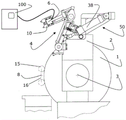
Figures 1 and 2 show an apparatus of known type for checking the dimensions of a crankshaft, in particular for checking the radial dimensions of a pin or crankpin 15, which pin or crankpin 15 moves with an orbital motion on a machine tool (for example, a computer numerical control "CNC" grinder), comprising a tool which is a grinding wheel 1 carried by a tool-holding slide 2, more particularly a grinding wheel slide rotating about a geometric axis 3. The apparatus may perform the inspection during the crankshaft machining process and/or before and/or after the process. The table comprises a main axis and a dead centre (not shown in the figures) which define a geometric axis of rotation 8. The crankshaft to be machined is mounted on the machine tool with its main axis aligned with the geometric axis 8. As a result, each crank pin 15 of the crankshaft orbits about the axis 8. Although the crank pin 15 rotates eccentrically about the axis 8 along a circular trajectory, the trajectory of the pin with respect to the tool-holder slide 2 may be substantially represented by an arc drawn by a dashed line and indicated by reference numeral 16.
The known device of fig. 1 and 2 comprises cA reference device 10 (in particular cA V-shaped device) having resting and reference surfaces intended to engage with the surfaces of the pin 15, and cA measuring device 6, known per se, the measuring device 6 being connected to the reference device 10 and being movable together with the reference device 10 (for example similar to the one shown in the previously cited patent application published as EP- cA-1118833), the reference device 10 being able to detect the radial displacement of the probe 17 and being electrically connected to cA processing and display unit 100, the processing and display unit 100 in turn being connected (in cA manner known per se, not shown in the figures) to the numerical control of the grinding machine. The probe 17 is connected to the reference device 10 to contact the surface of the pin 15 to be checked and moves in a measuring direction coinciding with the bisector of the V-shaped reference device 10, or slightly inclined with respect to the bisector of the V-shaped reference device 10, and passes through the V-shaped reference device 10 between the opposite resting and reference surfaces. The support means 4 is fixed to the tool-holding slide 2 and supports the V-shaped reference device 10 and the measuring device 6 in a movable manner so as to allow the movement of the V-shaped reference device 10 and the movement of the measuring device 6 so as to follow the orbital movement of the pin 15 to be inspected. As shown in the partial view of fig. 2, the supporting device 4 comprises a first coupling element 9, which first coupling element 9 is rotated by means of a pivot defining a first axis of rotation 7 parallel to the geometric axis of rotation 3 of the grinding wheel 1 and to the geometric axis of rotation 8 of the crankshaft to be checked. A second coupling element 12 carrying the reference device 10 is then rotatably coupled to the coupling element 9 by means of a second pivot defining a second rotation axis 11 parallel to the axes 3 and 8. As mentioned above, since the crank pin 15 to be checked during machining moves along an arc 16 with respect to the tool-holder slide 2, when the reference device 10 rests on the pin 15, the reference device 10 follows a similar trajectory and moves alternately from top to bottom and vice versa with a frequency (a few or a few tens of revolutions per minute) equal to the frequency of the orbital movement of the crank pin 15. This is due to the fact that: the inspection device according to the invention is carried by a tool-holding slide 2, which tool-holding slide 2, while the current numerically controlled grinding machines work on the crankpin 15, moves along the track "tracking" the crankpin 15, so that the tool (in particular the grinding wheel 1) remains in contact with the work surface. Obviously, the forward closing movement due to the removal of the stock (stock) is added to the lateral "tracking" movement.
A guide mechanism is associated with the support means 4 for guiding the arrangement of the V-shaped reference means 10 onto the pin 15 (which faces the inspection state of the apparatus) and comprises a limiting means 20 between the tool-holding slider 2 and the second coupling element 12. The guide mechanism (for example, described in the previously cited patent application published as EP- cA-1118833) limits the mutual movement of the components of the support device 4 so that, from the rest position of the apparatus to the inspection state of the apparatus, the V-shaped reference device 10 must, under the effect of gravity, follow cA trajectory parallel to the profile of the grinding wheel 1 and very close to the grinding wheel 1 (typically at cA distance of cA few millimetres from the grinding wheel 1).
The control device 50 for controlling the automatic displacement of the apparatus from the rest position towards the checking condition (and vice versa, from the rest position away from the checking condition) comprises a drive mechanism having a double-acting cylinder 38 (for example of the hydraulic type) for rotating the support device 4 anticlockwise or clockwise about the first axis 7, for example acting on the first coupling element 9. By the action of the mechanical stop and of the gravity acting on the equipment assembly, the anticlockwise rotation of the first coupling element 9 causes the lowering of the V-shaped reference device 10 towards the pin 15 to be checked, guided by the guide means, whereas the clockwise rotation of the first coupling element 9 causes the raising of the V-shaped reference device 10 away from the pin 15 to be checked towards the rest position.
Additional compensation means (not shown) may be provided to allow the position of the support means 4 on the grinding wheel slide 2 to be adjusted to compensate for the variation in the position of the pin 15 to be checked due to the wear of the grinding wheel 1.
Fig. 3 and 4 show a device according to the invention, which comprises many of the features of the known device of fig. 1 and 2 and which is likewise intended to be fixed to a tool holding slide, for example in a grinding machine. The control means 50 of the apparatus of fig. 3 and 4 have different features with respect to the above-described control means and comprise a programmable motor 60 (preferably but not necessarily a stepper motor) and a transmission 62 between the motor 60 and the support means 4, which transmission is shown for example in fig. 6, in which the cross-sections along three different sections are separated by two thick dashed lines.
Fig. 5 very schematically shows some components of a possible transmission 62, which in particular comprises a worm 64 and a bevel gear 66 coupled to the worm 64. The drive 68 is coupled to the programmable motor 60 by means of the worm 64 and the bevel gear 66 and cooperates with the assembly of support means, in particular with the coupling element 9. Fig. 6, 7, 8 and 9a to 9d show details of a particular transmission mechanism, which represents only an exemplary embodiment. In particular, the transmission mechanism 62 comprises a transmission body 63, which transmission body 63 is coupled to the programmable motor 60 and houses said worm 64, the bevel gear 66 and the driver 68 on a suitable base. The driver 68 is formed by an element with a substantially rotational symmetry that rotates coaxially with the bevel gear 66 and comprises a butterfly seat 70 (which can be seen in fig. 7 and 9), which butterfly seat 70 houses a flat end 71 of a rotating shaft 72, as shown in fig. 9a to 9d, which is connected to the coupling element 9, which represents the sequence of movements and how some internal components cooperate with each other. The assembly of the driver 68 and the support means, in particular the coupling element 9, are connected to each other by a coupling through a gap between the flat end 71 of the rotation shaft 72 and the butterfly base 70.
The drive 68 is connected to a bevel gear 66, which bevel gear 66 is coupled to a worm 64, which worm 64 is driven by the motor 60, for example by means of another pair of gears 65. The driver 68 has a portion 77, the portion 77 having a generally cylindrical outer surface, and the part 76 thereof being also cylindrical but of smaller diameter. The seat 67 of the transmission body 63, which houses the portion 77 of the driver 68, is also substantially cylindrical and comprises the part 69 with a larger radial dimension. The driver 68 defines a generally radial through bore 73 in communication with the butterfly base 70, the butterfly base 70 housing a bolt 74 and a spring 75 urging the bolt 74 outwardly. As mentioned above, the rotation shaft 72 is connected to the coupling element 9 of the support device 4.
A "grinding wheel wear restoration" or grinding wheel wear compensation mechanism comprises a shaft 80 (fig. 6), the two ends of the shaft 80 supporting two rollers arranged eccentrically with respect to the axis of rotation or shaft axis 83 of the shaft 80: an inner roller 82 in contact with the cylindrical surface of portion 77 of driver 68 and an outer roller 84 (also visible in fig. 3 and 4) acting on support means 4, more specifically it cooperates with limiting device 20.
In fig. 9a, the mechanism is shown in the measuring position, i.e. in the checking state: the V-shaped reference device 10 rests on the pin 15 and is free to move as the flat end 71 of the rotation shaft 72 can rotate freely in the wide part of the butterfly seat 70 (fig. 9a shows two possible extreme positions between which the flat end 71 of the rotation shaft 72 can rotate freely). The outer roller 84 is in the retracted position because the inner roller 82 rests on the portion 76 of the driver 68 having the smaller diameter. The motor 60 is stationary.
In the phase of movement in the retraction direction towards the rest position (fig. 9b and 9c), the driver 68 starts to rotate (in a counter-clockwise direction with reference to fig. 9a to 9 d) and starts to drag the shaft 72, then lifting the coupling element 9. At the same time, the outer roller 84 rotates in the same direction about the shaft axis 83, and due to its eccentricity, actually advances relative to the previously assumed position (toward the right, with reference to fig. 4).
Until this point, the bolt 74, pushed by the spring 75, is still in contact with the surface of the part 69 and has a greater radial dimension of the seat 67 and does not project into the butterfly seat 70.
From the state of fig. 9c to the state of fig. 9d, the counterclockwise rotation of the driver 68 carrying the flat end 71 of the rotary shaft 72 is continued, and at the same time, the bolt 74 encounters the surface diameter accommodating the seat 67 on which the driver 68 rests, which is changed due to the urging force of the spring 75, and the driver 68 is pushed to protrude inside the butterfly seat 70, thereby restricting the relative rotation between the shaft 72 and the driver 68. When the rest position corresponds to the arrangement of the components of the support device 4, this allows to lock the position of the first coupling element 9, which may result in a further movement of the apparatus in the retraction direction beyond the rest position due to gravity.
In the transition phase from the rest position to the checking state, the process is reversed. Moving towards the inspection state, during the rotation of the drive 68 in a clockwise direction (with reference to the views of fig. 9a to 9 d), the inner roller 82 rotates and causes the eccentric rotation of the outer roller 84, so that when the V-shaped device 10 is close to the pin 15 to be inspected, the surface of the outer roller 84 is pulled back with respect to the restraining means 20 (towards the left, see fig. 4), leaving room for a possible small amplitude of further rotation of the support means 4 about the first rotation axis 7, which allows any wear of the grinding wheel 1 to be restored, thus causing a small displacement of the pin 15 (towards the left, see fig. 4).
In a preferred embodiment of the invention, the bevel gear 66 and the driver 68 are not rigidly connected to each other, more specifically four or more rubber pads 78 (fig. 8) are arranged between them, and the rubber pads 78 act as dampers, allowing a mutual rotation of a small amplitude to absorb sudden torque variations.
The control device 50 with the programmable motor 60 allows the speed of the above-mentioned automatic displacement, i.e. the displacement speed of the V-shaped reference device 10 towards and away from the inspection state, to be flexibly defined and adjusted. In particular, the speed at which the automatic displacement of the device occurs from a certain position and the V-shaped reference device 10 moves towards the crank pin 15 while the crank pin 15 orbits may be defined, allowing to synchronize both movements (i.e. the automatic displacement of the device and the orbital movement of the crank pin 15) so that the contact between the V-shaped reference device 10 and the crank pin 15 occurs substantially smoothly without any significant hump, preferably when the crank pin 15 moves substantially at maximum speed away from the V-shaped reference device 10. This occurs when the pin 15 is in a central position aligned with the geometric axis of rotation 3 and 8 of the grinding wheel 1 and of the crankshaft, while the pin 15 descends towards the bottom dead centre of its path (figure 10). More specifically, the method for checking the diametral size of a pin 15 orbiting at a known rotation speed according to the invention comprises the following steps, but not necessarily in this order. A starting position of the apparatus (the starting position, i.e. the position where the reference device 10 is spaced from the pin 15) and a matching position of the pin 15 (the position where the reference device 10 is intended to engage the pin 15) are defined. For example, according to a preferred embodiment, the matching position is chosen as the above-mentioned central position, which is aligned with the geometric axis of rotation 3 and the geometric axis 8 of the grinding wheel 1 and of the crankshaft, while the pin 15 descends towards the bottom dead centre of its path. The travel time, which is the time the pin needs to cover the path between the predetermined angular position and the matching position in its orbital movement, is calculated based on the known rotation speed of the pin 15. The path may correspond to an angle of less than or greater than 360 deg.. The displacement speed of the device is calculated and the approach time is calculated as the time required to move the device (more specifically, the reference means 10) from the starting position of the pin 15 to the matching position. The displacement speed is set to: the approach time is shorter than the travel time, and the delay is calculated based on the travel and approach times. For example by means of a proximity switch (known per se but not shown in the figures), a transition instant (transit instant) is detected as the instant when the pin 15 is at the above-mentioned predetermined angular position during its orbital movement, and the starting instant is calculated on the basis of the above-mentioned transition instant and the delay. At the start time, the control device shifts from the start position to the displacement of the inspection state at the set shift speed. In this way, the V-shaped reference device 10 engages the pin 15 at the mating position of the pin 15 as defined above, and contact between the components occurs without any significant bulging that may cause negative bounce and physical damage.
When the V-shaped reference device 10 rests on the crank pin 15, its motion is completely independent of the motor 60. In particular, in the inspection state, substantially due to gravity (more specifically due to the displacement of the coupling elements 9, 12 due to gravity and to the thrust of the crank pin 15, which is opposite to the gravity of the components of the inspection apparatus), the correct fit between the crank pin 15 and the V-shaped reference device 10 is maintained.
The possibility of achieving a correct and flexible synchronization between the movement of the V-shaped reference device 10 and the orbital movement of the pin 15 allows to increase the limit of the maximum rotational speed at which the crankshaft can rotate when the V-shaped reference device 10 and the measuring device 8 are on the crank pin 15. Thus, the grinding cycle can be optimized without having to interrupt or slow down the machine cycle during the introduction phase.
The possibility of programming the electric motor 60 offers other advantages, such as the possibility of defining the rest position in an extremely simple and flexible manner. It is also possible to define at least an intermediate position in which the rearward movement of the support means 4 away from the inspection state can be stopped. Thereby, for example during inspection of the crankshaft, from one crank pin 15 to the next crank pin to be inspected, the entire path from the inspection state to the rest position can be avoided. The reduction of the travel path has a clear advantage in terms of time. In this case, the intermediate position can be selected and simply programmed according to the minimum retraction stroke required to withdraw the maximum radial dimension of the crankshaft part. In general, the possibility of programming the electric motor 60 in the device according to the invention allows to define in a simple and flexible way any starting position of the device, i.e. any position in which the reference means 10 are spaced from the pin 15 and are ready to be displaced towards the inspection state when the pin 15 moves along the track (for example according to the method described above) or when the pin 15 is at rest.
The input of driving or programming data of the programmable motor 60 may be performed, for example, by a physical I/O device or by serial communication. The programming data can be input directly into the programmable motor 60 or, more frequently, through an electronic unit present in the control device 50. The I/O device may be connected to a numerical control system of the machine tool.
In a preferred embodiment, the device according to the invention has an integrated diagnostic function. In particular, the control device 50 comprises, in addition to the electronic unit, position sensors, encoders and/or other components, the signals of which are processed by the electronic unit to monitor the system movements and safety parameters, and to know, for example, the position or displacement speed of the movable parts of the plant.
The rest position and any intermediate position can be defined very simply in a calibration phase.
Claims (14)
1. An apparatus for checking the diametral dimensions of a pin (15) orbiting around a geometric axis (8) in a numerically controlled machine tool having a tool-holding slide (2), said apparatus having:
a reference device (10) adapted to cooperate with a pin (15) to be checked,
a measuring device (6) which can be moved relative to the reference device (10),
-support means (4) adapted to be fixed to said tool-holding slide (2) for movably supporting said reference means (10) and said measuring means (6) to allow said reference means (10) to move so as to follow a pin (15) to be inspected, which moves along its trajectory, in an inspection state, maintaining a correct fit between the pin (15) to be inspected and said reference means (10) substantially due to gravity, and
control means (50) for controlling the automatic displacement of the device towards and away from the inspection state,
the control device (50) comprises an electric motor (60) and a transmission (62) between the electric motor (60) and the support device (4),
characterized in that the electric motor is a programmable electric motor (60) programmed to define a starting position in which automatic displacement of the apparatus away from the inspection state can be stopped, wherein the programmable electric motor (60) is programmed to define the starting position as an intermediate position of the reference device (10) between a rest position of the apparatus and the inspection state of the apparatus in which automatic displacement of the apparatus towards or away from the rest position can be stopped.
2. The apparatus of claim 1, wherein the programmable motor (60) is programmed to define a displacement speed of the automatic displacement.
3. Apparatus according to claim 2, wherein said programmable motor (60) is programmed to define said displacement speed at which said automatic displacement of the apparatus towards said inspection state takes place while the pin (15) to be inspected orbits, so as to synchronize said automatic displacement with the orbital motion of said pin (15).
4. Apparatus according to claim 3, wherein said programmable motor (60) is programmed to define said displacement speed such that contact occurs between said reference device (10) and said pin (15) when said pin (15) moves away from said reference device (10) substantially at a maximum speed.
5. Apparatus according to claim 4, wherein said programmable motor (60) is programmed to define a starting moment of said automatic displacement, so that contact occurs between said reference device (10) and said pin (15) when said pin (15) moves away from said reference device (10) substantially at maximum speed.
6. Apparatus according to any one of the preceding claims, wherein the starting position of the reference device is acquired in a calibration phase.
7. Apparatus according to any one of claims 1 to 5, wherein the transmission mechanism (62) comprises a drive (68) coupled to the assembly of support means (4), a worm (64) coupled to the programmable motor (60) and a helical gear (66) coupled to the worm, the worm being coupled to the drive (68).
8. Apparatus according to claim 7, wherein said driver (68) is adapted to rotate and is coupled to the assembly of said support means (4) by means of a coupling with clearance between a shaft (72) having a substantially flat section (71) and a butterfly-shaped base (70) of said driver (68).
9. Apparatus according to claim 8, wherein the driver (68) comprises a bolt (74), said bolt (74) being adapted to protrude into the butterfly base (70) during rotation of the driver (68) to constrain the relative rotation between the shaft (72) and the driver (68) and lock the position of the support device (4).
10. Apparatus according to any one of claims 1-5, comprising guide means associated with said support device (4) for guiding the arrangement of said reference devices (10) onto said pins (15) towards an inspection state of the apparatus.
11. Apparatus according to any one of claims 1-5, wherein said reference device (10) is a V-shaped device having a bearing and reference surface adapted to engage a surface of said pin (15).
12. Apparatus according to any one of claims 1-5, wherein the tool-holding slide (2) carries a grinding wheel (1) and the control device (50) comprises means for compensating the wear of the grinding wheel.
13. A method for checking the diametral dimensions of a pin (15) orbiting around a geometric axis (8) at a known rotation speed in a numerically controlled machine tool provided with a tool-holding slide (2), by means of an apparatus comprising:
-reference means (10) suitable for cooperating with a pin (15) to be checked,
a measuring device (6) movable with the reference device (10),
-a support device (4) adapted to be fixed to the tool-holding slide (2) for movably supporting the reference device (10) and the measuring device (6) to allow the reference device (10) to move so as to follow a pin (15) to be inspected, moving along its trajectory, and
-a control device (50) for controlling the displacement of the apparatus towards and away from an inspection state, the control device (50) having a programmable electric motor (60), in the inspection state the reference device (10) resting on the pin (15) to be inspected,
the method comprises the following steps, not necessarily in this order:
-defining a starting position of the device in which the reference means (10) are spaced apart from the pin (15),
-defining a matching position of the pin (15) in which the reference device (10) can engage the pin (15),
-calculating, based on the known rotation speed, the travel time required for the pin to cover, in its orbital movement, the path between the predetermined angular position and the matching position,
-defining a displacement speed of the device and calculating a closing time required for moving the device from a starting position to a matching position of the pin (15),
-calculating a delay from the travel time and the approach time,
-detecting a transition moment at which said pin (15) is located at said predetermined angular position during its orbital movement,
-calculating a start time based on said transition time and said delay, and
-controlling a shift of the device from a starting position to an inspection state at the starting moment.
14. Method according to claim 13, wherein the matching position is selected as the central position of the pin (15) aligned with the geometric axis (8) when the pin (15) orbits towards bottom dead centre of its path.
Applications Claiming Priority (3)
| Application Number | Priority Date | Filing Date | Title |
|---|---|---|---|
| IT102017000088988 | 2017-08-02 | ||
| IT102017000088988A IT201700088988A1 (en) | 2017-08-02 | 2017-08-02 | EQUIPMENT FOR THE CONTROL OF DIAMETER DIMENSIONS OF A PIN OF ORBITAL MOTION |
| PCT/EP2018/070839 WO2019025480A1 (en) | 2017-08-02 | 2018-08-01 | Apparatus and method for checking diametral dimensions of an orbitally rotating pin |
Publications (2)
| Publication Number | Publication Date |
|---|---|
| CN110997234A CN110997234A (en) | 2020-04-10 |
| CN110997234B true CN110997234B (en) | 2022-03-11 |
Family
ID=60570151
Family Applications (1)
| Application Number | Title | Priority Date | Filing Date |
|---|---|---|---|
| CN201880050230.5A Active CN110997234B (en) | 2017-08-02 | 2018-08-01 | Apparatus and method for checking diameter size of rail rotation pin |
Country Status (7)
| Country | Link |
|---|---|
| US (1) | US11268799B2 (en) |
| EP (1) | EP3661696B1 (en) |
| JP (1) | JP7282075B2 (en) |
| CN (1) | CN110997234B (en) |
| ES (1) | ES2935355T3 (en) |
| IT (1) | IT201700088988A1 (en) |
| WO (1) | WO2019025480A1 (en) |
Families Citing this family (4)
| Publication number | Priority date | Publication date | Assignee | Title |
|---|---|---|---|---|
| IT201700088988A1 (en) * | 2017-08-02 | 2019-02-02 | Marposs Spa | EQUIPMENT FOR THE CONTROL OF DIAMETER DIMENSIONS OF A PIN OF ORBITAL MOTION |
| EP3743677B1 (en) * | 2018-01-22 | 2021-04-28 | Reginald Galestien | Method and apparatus for measuring diameters of cylindrical measuring pins |
| CN114654313B (en) * | 2022-04-01 | 2023-03-17 | 江苏光扬轴承股份有限公司 | Lever type measuring device for internal grinding machine |
| CN117564808B (en) * | 2024-01-17 | 2024-03-15 | 山东普鲁特机床有限公司 | Quick testing arrangement of reliability of numerical control machining center |
Family Cites Families (13)
| Publication number | Priority date | Publication date | Assignee | Title |
|---|---|---|---|---|
| US4106241A (en) * | 1976-10-28 | 1978-08-15 | Fisk James C | Grinding gauge support |
| US4528876A (en) * | 1983-05-11 | 1985-07-16 | Crankshaft Machine Company | Universal single spindle pin crankshaft lathe |
| IT1213718B (en) * | 1987-11-09 | 1989-12-29 | Marposs Spa | APPARATUS FOR CHECKING CHARACTERISTICS OF PIECES WITH ROTATION SYMMETRY |
| IT1279641B1 (en) * | 1995-10-03 | 1997-12-16 | Marposs Spa | APPARATUS FOR CHECKING THE DIAMETER OF CONNECTING ROD PINS IN ORBITAL MOTION |
| IT1299902B1 (en) * | 1998-03-13 | 2000-04-04 | Marposs Spa | HEAD, EQUIPMENT AND METHOD FOR CHECKING LINEAR DIMENSIONS OF MECHANICAL PARTS. |
| ITBO20000012A1 (en) | 2000-01-18 | 2001-07-18 | Marposs Spa | PIN DIAMETER CONTROL EQUIPMENT. |
| WO2011013710A1 (en) | 2009-07-28 | 2011-02-03 | コマツNtc 株式会社 | Grinding machine and measurement device |
| DE102009042252B4 (en) * | 2009-09-22 | 2014-03-06 | Jenoptik Industrial Metrology Germany Gmbh | measuring device |
| DE102010013069B4 (en) | 2010-03-26 | 2012-12-06 | Hommel-Etamic Gmbh | measuring device |
| DE102012110673B4 (en) * | 2012-11-07 | 2014-05-15 | Fritz Studer Ag | Machine tool and method for measuring a workpiece |
| ES2731292T3 (en) * | 2013-09-16 | 2019-11-14 | Marposs Spa | Apparatus for verifying the diametral dimensions of wrists |
| DE102015115718B4 (en) * | 2015-09-17 | 2018-10-11 | Jenoptik Industrial Metrology Germany Gmbh | Roundness and / or dimension measuring device |
| IT201700088988A1 (en) * | 2017-08-02 | 2019-02-02 | Marposs Spa | EQUIPMENT FOR THE CONTROL OF DIAMETER DIMENSIONS OF A PIN OF ORBITAL MOTION |
-
2017
- 2017-08-02 IT IT102017000088988A patent/IT201700088988A1/en unknown
-
2018
- 2018-08-01 ES ES18745957T patent/ES2935355T3/en active Active
- 2018-08-01 JP JP2020505316A patent/JP7282075B2/en active Active
- 2018-08-01 WO PCT/EP2018/070839 patent/WO2019025480A1/en unknown
- 2018-08-01 EP EP18745957.3A patent/EP3661696B1/en active Active
- 2018-08-01 US US16/635,066 patent/US11268799B2/en active Active
- 2018-08-01 CN CN201880050230.5A patent/CN110997234B/en active Active
Also Published As
| Publication number | Publication date |
|---|---|
| WO2019025480A1 (en) | 2019-02-07 |
| EP3661696A1 (en) | 2020-06-10 |
| CN110997234A (en) | 2020-04-10 |
| JP7282075B2 (en) | 2023-05-26 |
| EP3661696B1 (en) | 2022-11-09 |
| IT201700088988A1 (en) | 2019-02-02 |
| JP2020529330A (en) | 2020-10-08 |
| ES2935355T3 (en) | 2023-03-06 |
| US20200249006A1 (en) | 2020-08-06 |
| US11268799B2 (en) | 2022-03-08 |
Similar Documents
| Publication | Publication Date | Title |
|---|---|---|
| CN110997234B (en) | Apparatus and method for checking diameter size of rail rotation pin | |
| JP5138130B2 (en) | In-process inspection device for the diameter of cylindrical parts | |
| US6067721A (en) | Apparatus for checking the diameter of crankpins rotating with an orbital motion | |
| KR0166398B1 (en) | Apparatus and method for machining a gear shape | |
| US7020974B2 (en) | Apparatus for checking the dimensional and geometric features of pins | |
| US6952884B2 (en) | Apparatus for checking dimensional and geometrical features of pins | |
| JP4762980B2 (en) | Method and apparatus for controlling machining of machine parts | |
| US6645047B1 (en) | Automatic gage head positioning system | |
| GB2531481A (en) | Round hole machining method and round-hole machining device | |
| CN105555477A (en) | Apparatus for checking diametral dimensions of pins | |
| CA2821810A1 (en) | Perfected grinding machine and grinding method | |
| US8069756B2 (en) | Apparatus for automatically detecting the position of the cutting tool in the computerized numerically controlled lathe | |
| CN1717297B (en) | A tool compensating device for the computerized numerically controlled machine tool | |
| RU131324U1 (en) | THREAD GRINDING MACHINE | |
| RU191596U1 (en) | MACHINE FOR PROCESSING SURFACES OF LARGE-SIZED PARTS-ROTATION BODIES | |
| RU2596526C1 (en) | Device for micro feed of workpieces for flat grinding | |
| JP2002292546A (en) | Grinding machine provided with steady rest and its grinding method |
Legal Events
| Date | Code | Title | Description |
|---|---|---|---|
| PB01 | Publication | ||
| PB01 | Publication | ||
| SE01 | Entry into force of request for substantive examination | ||
| SE01 | Entry into force of request for substantive examination | ||
| GR01 | Patent grant | ||
| GR01 | Patent grant |