CN110977262A - Flexible cabin automatic welding line and welding method thereof - Google Patents
Flexible cabin automatic welding line and welding method thereof Download PDFInfo
- Publication number
- CN110977262A CN110977262A CN201911375581.6A CN201911375581A CN110977262A CN 110977262 A CN110977262 A CN 110977262A CN 201911375581 A CN201911375581 A CN 201911375581A CN 110977262 A CN110977262 A CN 110977262A
- Authority
- CN
- China
- Prior art keywords
- welding
- cabin
- conveying
- parts
- line
- Prior art date
- Legal status (The legal status is an assumption and is not a legal conclusion. Google has not performed a legal analysis and makes no representation as to the accuracy of the status listed.)
- Granted
Links
- 238000003466 welding Methods 0.000 title claims abstract description 201
- 238000000034 method Methods 0.000 title claims abstract description 11
- 238000003860 storage Methods 0.000 claims abstract description 24
- 238000002360 preparation method Methods 0.000 claims abstract description 7
- 230000005540 biological transmission Effects 0.000 claims description 8
- 238000001514 detection method Methods 0.000 claims description 5
- 238000004519 manufacturing process Methods 0.000 abstract description 11
- WYROLENTHWJFLR-ACLDMZEESA-N queuine Chemical compound C1=2C(=O)NC(N)=NC=2NC=C1CN[C@H]1C=C[C@H](O)[C@@H]1O WYROLENTHWJFLR-ACLDMZEESA-N 0.000 description 3
- 238000003825 pressing Methods 0.000 description 2
- 238000010923 batch production Methods 0.000 description 1
- 230000007423 decrease Effects 0.000 description 1
- 238000010586 diagram Methods 0.000 description 1
- 230000007306 turnover Effects 0.000 description 1
- 238000005493 welding type Methods 0.000 description 1
Images


Classifications
-
- B—PERFORMING OPERATIONS; TRANSPORTING
- B23—MACHINE TOOLS; METAL-WORKING NOT OTHERWISE PROVIDED FOR
- B23K—SOLDERING OR UNSOLDERING; WELDING; CLADDING OR PLATING BY SOLDERING OR WELDING; CUTTING BY APPLYING HEAT LOCALLY, e.g. FLAME CUTTING; WORKING BY LASER BEAM
- B23K37/00—Auxiliary devices or processes, not specially adapted to a procedure covered by only one of the preceding main groups
- B23K37/02—Carriages for supporting the welding or cutting element
-
- B—PERFORMING OPERATIONS; TRANSPORTING
- B23—MACHINE TOOLS; METAL-WORKING NOT OTHERWISE PROVIDED FOR
- B23K—SOLDERING OR UNSOLDERING; WELDING; CLADDING OR PLATING BY SOLDERING OR WELDING; CUTTING BY APPLYING HEAT LOCALLY, e.g. FLAME CUTTING; WORKING BY LASER BEAM
- B23K37/00—Auxiliary devices or processes, not specially adapted to a procedure covered by only one of the preceding main groups
- B23K37/04—Auxiliary devices or processes, not specially adapted to a procedure covered by only one of the preceding main groups for holding or positioning work
- B23K37/0426—Fixtures for other work
- B23K37/0435—Clamps
- B23K37/0443—Jigs
Landscapes
- Physics & Mathematics (AREA)
- Optics & Photonics (AREA)
- Engineering & Computer Science (AREA)
- Mechanical Engineering (AREA)
- Automobile Manufacture Line, Endless Track Vehicle, Trailer (AREA)
- Automatic Assembly (AREA)
Abstract
The invention discloses a flexible cabin automatic welding line, which comprises a PLC control system, a conveying line, a transfer robot, a welding robot and a workpiece pre-positioning device, wherein the conveying line, the transfer robot and the welding robot are controlled by the PLC control system; the welding bench is provided with a conveying mechanism controlled by a PLC control system, one end of the conveying mechanism is located in the working range of the welding robot, the other end of the conveying mechanism is provided with a welding fixture storage table, and a set of welding fixtures arranged on the welding fixture storage table can be switched between a preparation station and a working station right facing the welding bench through the PLC control system. The invention also discloses a welding method of the welding line, which can obviously improve the production efficiency of the cabin welding line.
Description
Technical Field
The invention relates to the technical field of automobile assembly, in particular to a flexible cabin automatic welding line and a welding method thereof.
Background
In order to meet the demand of market diversification, automobile manufacturers are continuously developing new products, and a multi-vehicle type and small-batch production mode is adopted. In this situation, if a conventional production line corresponds to a model of a vehicle type, the production cost tends to increase greatly, and thus it is necessary to develop a flexible production line capable of producing a plurality of vehicle types. The engine room formed by welding the front longitudinal beam, the engine hood supporting edge and the front wall assembly is one of important component modules of an automobile body. During production, different types of cabins need to correspond to different types of welding fixtures. If simply arrange multiple welding jig on a production line according to traditional mode, not only there is the problem that the line body is long, area is big, and equipment idle rate along the line is higher moreover, the overall production efficiency of the line body is lower, and cabin manufacturing cost can not show the decline.
Disclosure of Invention
In order to solve the problems, the invention provides a flexible cabin automatic welding line with small occupied area and high production efficiency, and simultaneously provides a welding method based on the welding line, which adopts the following technical scheme:
the flexible cabin automatic welding line comprises a PLC control system and a welding line body, wherein the welding line body is controlled by the PLC control system:
the conveying line is used for carrying cabin parts and cabin finished products;
the transfer robot is used for clamping the cabin parts and/or cabin finished products to transfer positions of the cabin parts and/or cabin finished products;
the welding robot is used for welding the cabin parts fixed on the set of welding fixtures to form the cabin finished product, and the set of welding fixtures are fixed on the horizontal base;
also comprises
The workpiece pre-positioning device is used for storing cabin parts transferred from the conveying line, and is provided with a model identification and transmission mechanism which is used for acquiring model data information of the cabin parts and transmitting the model data information to the PLC control system;
a welding workbench provided with a conveying mechanism controlled by a PLC control system, one end of the conveying mechanism is positioned in the working range of the welding robot, and the other end is provided with a
The welding fixture storage table is arranged on a moving mechanism controlled by a PLC control system, and the moving mechanism enables the set of welding fixtures arranged on the welding fixture storage table to be switched between a preparation station and a working station just facing the welding workbench.
The workpiece pre-positioning device is provided with a positioning column for fixing engine room parts, and the model identification transmission mechanism is a photoelectric detection switch arranged on the positioning column.
The welding fixture storage table is of a straight prism structure, and each side face of the straight prism is provided with one set of welding fixture.
The moving mechanism is a rotating base connected with the right prism.
The welding workbench is of a linear structure, the conveying mechanism is a conveying chain driven by a servo motor, welding fixture fixing parts are arranged on the conveying chain and used for connecting the horizontal base to enable the welding fixture set to move between the storage platforms of the welding robot and the welding fixture set in the working range of the welding robot.
The workpiece pre-positioning devices are arranged on two sides of the welding workbench.
The welding method of the flexible cabin automatic welding line comprises the following steps:
firstly, transporting cabin parts mounted on a conveying line to the vicinity of a workpiece prepositioning device;
secondly, transferring the cabin parts from the conveying line to a workpiece pre-positioning device through a transfer robot, and acquiring model data information of the cabin parts by a model identification and transmission mechanism on the transfer robot and transmitting the model data information to a PLC (programmable logic controller) control system;
thirdly, matching a corresponding set of welding fixtures by the PLC control system according to the model data information, and transferring the set of welding fixtures to a working station right opposite to the welding workbench by controlling a moving mechanism of a welding fixture storage table to rotate;
fourthly, mounting the set of welding fixture in the third step on a conveying mechanism of a welding workbench, mounting cabin parts on the workpiece pre-positioning device on the set of welding fixture through a transfer robot, starting the conveying mechanism to work, transferring the set of welding fixture and the cabin parts on the set of welding fixture to one end close to the welding robot along the welding workbench, and welding the cabin parts into a cabin finished product through the welding robot;
fifthly, transferring the cabin finished product to a conveying line by a transfer robot and conveying the cabin finished product to the next station; meanwhile, the complete set of welding fixture is transferred to the welding fixture storage table through the conveying mechanism of the welding workbench to be placed, and one-time welding is completed.
The flexible cabin automatic welding line provided by the invention is simple in structure and reasonable in layout, the occupied area of the device can be greatly reduced, the equipment is prevented from being repeatedly input by reasonably matching the welding fixture storage table, the welding workbench and the like during welding, the phenomenon of high equipment idle rate is changed, the early-stage cost of the cabin welding line is greatly reduced, and the production efficiency of the cabin welding line is obviously improved.
Drawings
FIG. 1 is a schematic view of the structure of the bonding wire of the present invention (omitting the conveying wire).
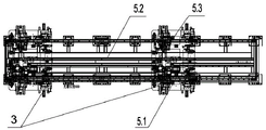
Fig. 2 is a schematic structural view of the welding table of fig. 1.
Fig. 3 is a schematic view of the structure of the welding jig fixing member of fig. 2.
Fig. 4 is a schematic structural view of a welding jig storage table in fig. 1.
Fig. 5 is a schematic structural view of the support bracket on the left side in fig. 4.
Fig. 6 is a block diagram of the circuit control principle of the present invention.
Detailed Description
The following describes embodiments of the present invention in detail with reference to the drawings, and the embodiments and specific operations of the embodiments are provided on the premise of the technical solution of the present invention, but the scope of the present invention is not limited to the following embodiments.
The flexible cabin automatic welding line comprises a PLC control system, a conveying line controlled by the control system, a transfer robot 1 and a welding robot 2, wherein the conveying line is used for carrying cabin parts and cabin finished products; the transfer robot 1 is used for clamping the cabin parts and/or cabin finished products to transfer the positions of the cabin parts and/or cabin finished products; welding robot 2 is used for welding the cabin spare part of fixing on complete set welding jig 3 into the cabin finished product, and above-mentioned complete set welding jig 3 is fixed on horizontal base Q, makes things convenient for overall movement, location. In order to arrange the welding line in a limited space and meet the welding of various engine cabins, the welding line also protects a specially designed workpiece pre-positioning device 4, a welding workbench 5 and a welding fixture storage table 6. Wherein, prepositioning device 4 is installed in welding bench 5 both sides, and welding robot 2 and welding jig deposit 6 branch puts at welding bench 5 both ends.
The workpiece pre-positioning device 4 is used for storing cabin parts transferred from a conveying line, and is provided with a model identification and transmission mechanism which is used for acquiring model data information of the cabin parts and transmitting the model data information to the PLC control system. Specifically, as shown in fig. 1, the workpiece pre-positioning device 4 comprises supports 4.1 for accommodating various cabin components, each support 4.1 is provided with a positioning column 4.2 for fixing the cabin components, and a photoelectric detection switch 4.3 is arranged near the positioning column 4.2 as a model identification transmission mechanism.
The welding workbench 5 is provided with a conveying mechanism controlled by a PLC control system, one end of the conveying mechanism is positioned in the working range of the welding robot 2, and the other end of the conveying mechanism is connected with a welding clamp storage table 6. Specifically, as shown in fig. 2 and 3, the surface of the welding workbench 5 is a linear structure, a conveying chain 5.2 driven by a servo motor 5.1 is installed below the welding workbench, a welding fixture fixing member 5.3 is installed on the conveying chain 5.2, and the welding fixture fixing member 5.3 comprises a fixing base plate 5.3.1 on which a vertical pneumatic telescopic pin 5.3.3 controlled by an air source connecting switch 5.3.2 is arranged. When the horizontal base Q of the welding jig set 3 is fixed on the vertical pneumatic telescopic pin 5.3.3 of the welding jig fixing member 5.3, it can move between the working range of the welding robot 2 and the welding jig storage table 6 under the action of the conveying chain 5.2.
The welding jig storage table 6 is provided on a moving mechanism controlled by a PLC control system, and the welding jig set stored thereon can be switched between a preparation station and a working station facing the welding table 5. In general, the vertical surface of the welding jig storage table 6 facing the welding table 5 is referred to as a "work station", and the vertical surfaces in other directions are referred to as "preparation stations".
Specifically, as shown in fig. 4, the moving mechanism is a rotating base 6.1, the welding jig storage table 6 is a regular quadrangular prism 6.2, and a set of welding jigs 3 is mounted on each side surface of the regular quadrangular prism 6.2. The rotating base 6.1 is driven by a rotating motor, and the control input end of the rotating motor is connected with the control output end of a PLC control system, so that each vertical face of the regular quadrangular prism 6.2 is switched between a working station and a preparation station.
As shown in fig. 5, taking the left side of the regular quadrangular prism 6.2 as an example, a supporting frame 6.2.1 for supporting the welding jig set 3 is installed thereon, the left side of the supporting frame 6.2.1 is installed with a turnover pneumatic pressing block 6.2.2 for fixing the welding jig set 3, the right side is installed with a mechanical limit stop 6.2.3, and the front and rear sides are installed with positioning guide wheels 6.2.4 for facilitating the welding jig set 3 to get in and out of the frame body.
In general, the conveyor chain 5.2 extends as far as below the "work station" of the regular quadrangular prism 6.2 in order to transfer the set of welding jigs 3 between the welding-jig mounts 5.3 and the regular quadrangular prism 6.2. When the set of welding fixture 3 is to be transferred to the welding workbench 5, firstly, the welding fixture fixing part 5.3 is transferred to the lower part of the set of welding fixture 3, the vertical pneumatic telescopic pin 5.3.3 is inserted into the corresponding pin hole of the horizontal base Q of the set of welding fixture 3, then, the pneumatic pressing block 6.2.2 is turned over to release the clamping of the set of welding fixture 3, the conveying chain 5.2 is started, the welding fixture fixing part 5.3 brings the set of welding fixture 3 to the welding workbench 5, and the action process that the welding fixture 3 is transferred to the welding workbench 5 from the 'working station' of the regular quadrangular 6.2 is completed. After the welding is completed, the welding jig fixing part 5.3 transfers the welding jig 3 from the welding workbench 5 to the 'working station' of the regular quadrangular prism 6.2.
By adopting the flexible cabin automatic welding line, the following welding method can be adopted, and the specific steps are as follows:
firstly, transporting cabin parts mounted on a conveying line to the vicinity of a workpiece prepositioning device 4;
secondly, grabbing the parts of the cabin to be welded on the conveying line through the transfer robot 1, placing the parts on a positioning column 4.2 of the workpiece pre-positioning device 4, and acquiring model data information of the parts of the cabin through a photoelectric detection switch 4.3 and transmitting the model data information to a PLC control system;
thirdly, the PLC control system matches a corresponding set of welding fixtures 3 according to the model data information, and the set of welding fixtures 3 are transferred to a working station facing the welding workbench 5 by controlling the rotation of a moving mechanism of the welding fixture storage table 6;
as shown in fig. 6, the PLC control system operates as follows: when the photoelectric detection switch 4.3 detects the model information of the parts of the cabin to be welded, the model information is transmitted to the PLC control system, the PLC control system judges whether the whole set of welding fixture 3 positioned at the work station is matched with the parts of the cabin to be welded, if so, a signal is sent out to enable the conveying chain 5.2 to drive the welding fixture fixing part 5.3 to move, and the whole set of welding fixture 3 is transferred to the welding fixture fixing part 5.3 from the regular quadrangular prism 6.2; if not, the PLC control system sends a signal to enable the rotating base 6.1 to drive the regular quadrangular prism 6.2 to rotate until the set of welding fixture 3 matched with the parts of the cabin to be welded is transferred from the 'preparation station' to the 'working station', and then the set of welding fixture 3 is transferred from the regular quadrangular prism 6.2 to the welding fixture fixing part 5.3.
Fourthly, after the required set of welding fixture 3 is installed on a welding fixture fixing part 5.3 of a welding workbench 5, the cabin parts to be welded on the workpiece pre-positioning device are installed on the set of welding fixture 3 through a transfer robot 1, then a conveying chain 5.2 starts to work, the set of welding fixture 3 and the cabin parts on the set of welding fixture 3 are transferred to one end close to the welding robot 2 along the welding workbench 5, and the cabin parts are welded into a cabin finished product through the welding robot 2;
fifthly, transferring the cabin finished product to a conveying line through the transfer robot 1 and conveying the cabin finished product to the next station; meanwhile, the whole set of welding fixture 3 is transported back to the welding fixture storage table 5 to be placed again through the conveying chain 5.2 on the welding workbench 5, and one-time welding is completed.
Above-mentioned welding jig can place many sets of welding jig 3, and its is small, rotate in a flexible way, uses the back with 5 cooperations of weldment work platform that have conveying mechanism, can effectively reduce the repeated input of all the other equipment, has not only reduced the earlier stage cost of cabin welding line, has reduced equipment area, has changed the higher phenomenon of equipment idle rate moreover, has improved the production efficiency of cabin welding line by a wide margin.
Claims (7)
1. A flexible cabin automatic welding line comprises a PLC control system and a welding line body, wherein the welding line body is controlled by the PLC control system:
the conveying line is used for carrying cabin parts and cabin finished products;
the transfer robot is used for clamping the cabin parts and/or cabin finished products to transfer positions of the cabin parts and/or cabin finished products;
the welding robot is used for welding the cabin parts fixed on the set of welding fixtures to form the cabin finished product, and the set of welding fixtures are fixed on the horizontal base;
the method is characterized in that: also comprises
The workpiece pre-positioning device is used for storing cabin parts transferred from the conveying line, and is provided with a model identification and transmission mechanism which is used for acquiring model data information of the cabin parts and transmitting the model data information to the PLC control system;
a welding workbench provided with a conveying mechanism controlled by a PLC control system, one end of the conveying mechanism is positioned in the working range of the welding robot, and the other end is provided with a
The welding fixture storage table is arranged on a moving mechanism controlled by a PLC control system, and the moving mechanism enables the set of welding fixtures arranged on the welding fixture storage table to be switched between a preparation station and a working station just facing the welding workbench.
2. The flexible nacelle automatic welding line according to claim 1, wherein: the workpiece pre-positioning device is provided with a positioning column for fixing engine room parts, and the model identification transmission mechanism is a photoelectric detection switch arranged on the positioning column.
3. The flexible nacelle automatic welding line according to claim 1, wherein: the welding fixture storage table is of a straight prism structure, and each side face of the straight prism is provided with one set of welding fixture.
4. The flexible nacelle automatic welding line according to claim 3, wherein: the moving mechanism is a rotating base connected with the right prism.
5. The flexible nacelle automatic welding line according to claim 1, wherein: the welding workbench is of a linear structure, the conveying mechanism is a conveying chain driven by a servo motor, welding fixture fixing parts are arranged on the conveying chain and used for connecting the horizontal base to enable the welding fixture set to move between the storage platforms of the welding robot and the welding fixture set in the working range of the welding robot.
6. The flexible nacelle automatic welding line according to claim 1, wherein: the workpiece pre-positioning devices are arranged on two sides of the welding workbench.
7. The welding method of the flexible cabin automatic welding line according to claim 1, characterized in that: the method comprises the following steps:
firstly, transporting cabin parts mounted on a conveying line to the vicinity of a workpiece prepositioning device;
secondly, transferring the cabin parts from the conveying line to a workpiece pre-positioning device through a transfer robot, and acquiring model data information of the cabin parts by a model identification and transmission mechanism on the transfer robot and transmitting the model data information to a PLC (programmable logic controller) control system;
thirdly, matching a corresponding set of welding fixtures by the PLC control system according to the model data information, and transferring the set of welding fixtures to a working station right opposite to the welding workbench by controlling a moving mechanism of a welding fixture storage table to rotate;
fourthly, mounting the set of welding fixture in the third step on a conveying mechanism of a welding workbench, mounting cabin parts on the workpiece pre-positioning device on the set of welding fixture through a transfer robot, starting the conveying mechanism to work, transferring the set of welding fixture and the cabin parts on the set of welding fixture to one end close to the welding robot along the welding workbench, and welding the cabin parts into a cabin finished product through the welding robot;
fifthly, transferring the cabin finished product to a conveying line by a transfer robot and conveying the cabin finished product to the next station; meanwhile, the complete set of welding fixture is transferred to the welding fixture storage table through the conveying mechanism of the welding workbench to be placed, and one-time welding is completed.
Priority Applications (1)
| Application Number | Priority Date | Filing Date | Title |
|---|---|---|---|
| CN201911375581.6A CN110977262B (en) | 2019-12-27 | 2019-12-27 | Welding method for automatic welding line of flexible engine room |
Applications Claiming Priority (1)
| Application Number | Priority Date | Filing Date | Title |
|---|---|---|---|
| CN201911375581.6A CN110977262B (en) | 2019-12-27 | 2019-12-27 | Welding method for automatic welding line of flexible engine room |
Publications (2)
| Publication Number | Publication Date |
|---|---|
| CN110977262A true CN110977262A (en) | 2020-04-10 |
| CN110977262B CN110977262B (en) | 2024-04-09 |
Family
ID=70077791
Family Applications (1)
| Application Number | Title | Priority Date | Filing Date |
|---|---|---|---|
| CN201911375581.6A Active CN110977262B (en) | 2019-12-27 | 2019-12-27 | Welding method for automatic welding line of flexible engine room |
Country Status (1)
| Country | Link |
|---|---|
| CN (1) | CN110977262B (en) |
Cited By (2)
| Publication number | Priority date | Publication date | Assignee | Title |
|---|---|---|---|---|
| CN113909803A (en) * | 2021-09-13 | 2022-01-11 | 云南昆船环保技术有限公司 | Intelligent continuous production method for square cabin |
| CN114905202A (en) * | 2022-04-29 | 2022-08-16 | 东风柳州汽车有限公司 | Welding production line |
Citations (9)
| Publication number | Priority date | Publication date | Assignee | Title |
|---|---|---|---|---|
| CN101569969A (en) * | 2009-05-05 | 2009-11-04 | 四川成焊宝玛焊接装备工程有限公司 | Automotive body robot flexible welding system for mixed line production of multiple vehicle types |
| CN203140998U (en) * | 2012-12-27 | 2013-08-21 | 广州市聚维专用汽车零部件有限公司 | Robot flexible-welding system for various non-standard components of special vehicles |
| CN104400267A (en) * | 2014-11-06 | 2015-03-11 | 安徽江淮汽车股份有限公司 | Automobile engine compartment welding production line |
| CN104923934A (en) * | 2015-06-11 | 2015-09-23 | 东华大学 | All-side rotation clamp based flexible production workstation for automobile welding production line |
| CN106378557A (en) * | 2016-11-16 | 2017-02-08 | 郑州日产汽车有限公司 | Flexible production line suitable for automobile side body production |
| CN206200449U (en) * | 2016-11-16 | 2017-05-31 | 郑州日产汽车有限公司 | It is suitable to the tetrahedron rolling clamp of vehicle side wire body Flexible Production |
| CN106735993A (en) * | 2017-02-24 | 2017-05-31 | 武汉瑞松北斗汽车装备有限公司 | A kind of car engine room assembly flexible automatic production line |
| CN208289266U (en) * | 2018-04-27 | 2018-12-28 | 比亚迪股份有限公司 | Welding and assembling production lines, be welded work station and the system that is welded |
| CN211589000U (en) * | 2019-12-27 | 2020-09-29 | 郑州日产汽车有限公司 | Flexible cabin automatic welding line |
-
2019
- 2019-12-27 CN CN201911375581.6A patent/CN110977262B/en active Active
Patent Citations (9)
| Publication number | Priority date | Publication date | Assignee | Title |
|---|---|---|---|---|
| CN101569969A (en) * | 2009-05-05 | 2009-11-04 | 四川成焊宝玛焊接装备工程有限公司 | Automotive body robot flexible welding system for mixed line production of multiple vehicle types |
| CN203140998U (en) * | 2012-12-27 | 2013-08-21 | 广州市聚维专用汽车零部件有限公司 | Robot flexible-welding system for various non-standard components of special vehicles |
| CN104400267A (en) * | 2014-11-06 | 2015-03-11 | 安徽江淮汽车股份有限公司 | Automobile engine compartment welding production line |
| CN104923934A (en) * | 2015-06-11 | 2015-09-23 | 东华大学 | All-side rotation clamp based flexible production workstation for automobile welding production line |
| CN106378557A (en) * | 2016-11-16 | 2017-02-08 | 郑州日产汽车有限公司 | Flexible production line suitable for automobile side body production |
| CN206200449U (en) * | 2016-11-16 | 2017-05-31 | 郑州日产汽车有限公司 | It is suitable to the tetrahedron rolling clamp of vehicle side wire body Flexible Production |
| CN106735993A (en) * | 2017-02-24 | 2017-05-31 | 武汉瑞松北斗汽车装备有限公司 | A kind of car engine room assembly flexible automatic production line |
| CN208289266U (en) * | 2018-04-27 | 2018-12-28 | 比亚迪股份有限公司 | Welding and assembling production lines, be welded work station and the system that is welded |
| CN211589000U (en) * | 2019-12-27 | 2020-09-29 | 郑州日产汽车有限公司 | Flexible cabin automatic welding line |
Cited By (3)
| Publication number | Priority date | Publication date | Assignee | Title |
|---|---|---|---|---|
| CN113909803A (en) * | 2021-09-13 | 2022-01-11 | 云南昆船环保技术有限公司 | Intelligent continuous production method for square cabin |
| CN114905202A (en) * | 2022-04-29 | 2022-08-16 | 东风柳州汽车有限公司 | Welding production line |
| CN114905202B (en) * | 2022-04-29 | 2023-07-07 | 东风柳州汽车有限公司 | Welding production line |
Also Published As
| Publication number | Publication date |
|---|---|
| CN110977262B (en) | 2024-04-09 |
Similar Documents
| Publication | Publication Date | Title |
|---|---|---|
| CN106733429B (en) | Dispensing and laminating machine | |
| WO2020057024A1 (en) | Flexible and automatic production line for punching, welding, or bonding automobile exterior decorative member | |
| CN109128616A (en) | A kind of automobile body-in-white flexible welding tooling | |
| JP3780745B2 (en) | Heme processing method and hem processing apparatus | |
| JPH03287328A (en) | Assembling device for automobile car body | |
| CN211589000U (en) | Flexible cabin automatic welding line | |
| CA2498168A1 (en) | Flexible body workstation for assembling workpieces | |
| CN110977262B (en) | Welding method for automatic welding line of flexible engine room | |
| CN114013536B (en) | Vehicle assembly line and vehicle assembly process | |
| US4744500A (en) | Vehicle assembly system | |
| US8312611B2 (en) | Assembling method and apparatus for assembly, and assembling method and apparatus for workpiece | |
| JPH04193434A (en) | Working line for rear floor of vehicle | |
| JPS63306110A (en) | Conveying device | |
| JPH1086867A (en) | Automobile door production device | |
| CN112719482A (en) | Elbow tapping feeding device and feeding method | |
| CN218385129U (en) | Automatic shaping diode lead wire installation diode device | |
| CN108946098A (en) | A kind of line side clamp fixture automatic switching control equipment | |
| CN110202296B (en) | Door planking loading attachment on car installation assembly line | |
| CN114193052A (en) | Automatic feeding device and production line | |
| CN112658519A (en) | Welding production line and production process | |
| CN110668186A (en) | Material conveying device | |
| US5267385A (en) | Automatic assembly apparatus | |
| CN112248245A (en) | Automatic processing production method | |
| CN112570943B (en) | Welding production line alternate feeding clamping and positioning system for protective type vehicle | |
| JP3085193B2 (en) | Automotive main body assembly equipment |
Legal Events
| Date | Code | Title | Description |
|---|---|---|---|
| PB01 | Publication | ||
| PB01 | Publication | ||
| SE01 | Entry into force of request for substantive examination | ||
| SE01 | Entry into force of request for substantive examination | ||
| GR01 | Patent grant | ||
| GR01 | Patent grant |