CN110891524A - Method and system for assisting or repairing a prosthetic heart valve - Google Patents
Method and system for assisting or repairing a prosthetic heart valve Download PDFInfo
- Publication number
- CN110891524A CN110891524A CN201880023901.9A CN201880023901A CN110891524A CN 110891524 A CN110891524 A CN 110891524A CN 201880023901 A CN201880023901 A CN 201880023901A CN 110891524 A CN110891524 A CN 110891524A
- Authority
- CN
- China
- Prior art keywords
- valve
- leaflet
- coaptation
- prosthetic
- prosthetic valve
- Prior art date
- Legal status (The legal status is an assumption and is not a legal conclusion. Google has not performed a legal analysis and makes no representation as to the accuracy of the status listed.)
- Pending
Links
Images


Classifications
-
- A—HUMAN NECESSITIES
- A61—MEDICAL OR VETERINARY SCIENCE; HYGIENE
- A61F—FILTERS IMPLANTABLE INTO BLOOD VESSELS; PROSTHESES; DEVICES PROVIDING PATENCY TO, OR PREVENTING COLLAPSING OF, TUBULAR STRUCTURES OF THE BODY, e.g. STENTS; ORTHOPAEDIC, NURSING OR CONTRACEPTIVE DEVICES; FOMENTATION; TREATMENT OR PROTECTION OF EYES OR EARS; BANDAGES, DRESSINGS OR ABSORBENT PADS; FIRST-AID KITS
- A61F2/00—Filters implantable into blood vessels; Prostheses, i.e. artificial substitutes or replacements for parts of the body; Appliances for connecting them with the body; Devices providing patency to, or preventing collapsing of, tubular structures of the body, e.g. stents
- A61F2/02—Prostheses implantable into the body
- A61F2/24—Heart valves ; Vascular valves, e.g. venous valves; Heart implants, e.g. passive devices for improving the function of the native valve or the heart muscle; Transmyocardial revascularisation [TMR] devices; Valves implantable in the body
- A61F2/2442—Annuloplasty rings or inserts for correcting the valve shape; Implants for improving the function of a native heart valve
- A61F2/2466—Delivery devices therefor
-
- A—HUMAN NECESSITIES
- A61—MEDICAL OR VETERINARY SCIENCE; HYGIENE
- A61F—FILTERS IMPLANTABLE INTO BLOOD VESSELS; PROSTHESES; DEVICES PROVIDING PATENCY TO, OR PREVENTING COLLAPSING OF, TUBULAR STRUCTURES OF THE BODY, e.g. STENTS; ORTHOPAEDIC, NURSING OR CONTRACEPTIVE DEVICES; FOMENTATION; TREATMENT OR PROTECTION OF EYES OR EARS; BANDAGES, DRESSINGS OR ABSORBENT PADS; FIRST-AID KITS
- A61F2/00—Filters implantable into blood vessels; Prostheses, i.e. artificial substitutes or replacements for parts of the body; Appliances for connecting them with the body; Devices providing patency to, or preventing collapsing of, tubular structures of the body, e.g. stents
- A61F2/02—Prostheses implantable into the body
- A61F2/24—Heart valves ; Vascular valves, e.g. venous valves; Heart implants, e.g. passive devices for improving the function of the native valve or the heart muscle; Transmyocardial revascularisation [TMR] devices; Valves implantable in the body
- A61F2/2442—Annuloplasty rings or inserts for correcting the valve shape; Implants for improving the function of a native heart valve
- A61F2/2454—Means for preventing inversion of the valve leaflets, e.g. chordae tendineae prostheses
-
- A—HUMAN NECESSITIES
- A61—MEDICAL OR VETERINARY SCIENCE; HYGIENE
- A61F—FILTERS IMPLANTABLE INTO BLOOD VESSELS; PROSTHESES; DEVICES PROVIDING PATENCY TO, OR PREVENTING COLLAPSING OF, TUBULAR STRUCTURES OF THE BODY, e.g. STENTS; ORTHOPAEDIC, NURSING OR CONTRACEPTIVE DEVICES; FOMENTATION; TREATMENT OR PROTECTION OF EYES OR EARS; BANDAGES, DRESSINGS OR ABSORBENT PADS; FIRST-AID KITS
- A61F2/00—Filters implantable into blood vessels; Prostheses, i.e. artificial substitutes or replacements for parts of the body; Appliances for connecting them with the body; Devices providing patency to, or preventing collapsing of, tubular structures of the body, e.g. stents
- A61F2/02—Prostheses implantable into the body
- A61F2/24—Heart valves ; Vascular valves, e.g. venous valves; Heart implants, e.g. passive devices for improving the function of the native valve or the heart muscle; Transmyocardial revascularisation [TMR] devices; Valves implantable in the body
- A61F2/2442—Annuloplasty rings or inserts for correcting the valve shape; Implants for improving the function of a native heart valve
- A61F2/2463—Implants forming part of the valve leaflets
Landscapes
- Health & Medical Sciences (AREA)
- Cardiology (AREA)
- Oral & Maxillofacial Surgery (AREA)
- Transplantation (AREA)
- Engineering & Computer Science (AREA)
- Biomedical Technology (AREA)
- Heart & Thoracic Surgery (AREA)
- Vascular Medicine (AREA)
- Life Sciences & Earth Sciences (AREA)
- Animal Behavior & Ethology (AREA)
- General Health & Medical Sciences (AREA)
- Public Health (AREA)
- Veterinary Medicine (AREA)
- Prostheses (AREA)
Abstract
A prosthetic valve coaptation assist device includes an anchor and a single valve assist leaflet. The anchors may be support ring frames, struts or arcuate structures, and will generally be radially self-expandable such that they may expand against surrounding native or artificial tissue. The valve assist leaflet may be made of pericardium or other biological or artificial material and shaped to resemble a native target valve leaflet. The valve assist leaflets are typically larger in size than the target native or artificial leaflets, so that significant overlap of the device body occurs after implantation.
Description
Cross Reference to Related Applications
The present application claims priority from U.S. provisional patent application No. 62/570,336 (attorney docket nos. 49792-704.102) filed on 10.10.2017 and U.S. provisional patent application No. 62/455,427 (attorney docket nos. 49792-704.101) filed on 6.2.2017, the entire disclosures of which are incorporated herein by reference.
The subject matter of this application also relates to the subject matter of U.S. patent application No. 14/901,468 (attorney docket nos. 49792-702.201) filed on 28/12/2015, which U.S. patent application No. 14/901,468 is the U.S. national phase project of PCT application No. PCT/IB2014/002155 (attorney docket nos. 49792-703.601) filed on 13/6/2014, while PCT application No. PCT/IB2014/002155 requires U.S. provisional patent application No. 61/956,683 (attorney docket nos. 49792-703.101) filed on 14/6/2013; U.S. provisional patent application No. 61/963,330 (attorney docket nos. 49792-703.102) filed on 2.12.2013; and U.S. provisional patent application No. 61/982,307 (attorney docket nos. 49792-703.103), filed on 21/4/2014, the entire disclosure of which is incorporated herein by reference.
Background
1. The field of the invention.The present invention relates generally to medical devices and methods. More particularly, the present invention relates to prosthetic devices and methods for improving the function of prolapsed heart and other circulatory valves.
Mitral insufficiency (MVI), whether organic (primary) or functional (secondary), such as, but not limited to, prolapse, regurgitation and flutter, is a heart valve disease characterized by the displacement of abnormally thickened mitral leaflets into the left atrium during systole, which can lead to poor coaptation of individual valve leaflets and valve weeping under back pressure. There are various types of MVIs, broadly classified as typical and atypical. In its atypical form, MVI carries a lower risk of complications and can often be kept to a minimum by careful diet. In severe cases of typical MVI, complications include mitral regurgitation, infectious endocarditis, congestive heart failure, and in rare cases cardiac arrest, which typically results in sudden death. The aortic valve may also be afflicted with prolapse, and the valves of the venous circulation may be afflicted with a similar condition that may result in chronic venous insufficiency caused by damaged or "incompetent" valves characterized by malarticulation.
It would be desirable to provide devices and methods for improving valve function in a patient suffering from any of the conditions identified above, and in particular, for improving coaptation of heart valves, including both mitral and aortic valves, as well as venous valves. At least some of these objectives will be met by the invention described hereinafter.
2. Background of the invention is described.U.S. patent nos. 6,419,695, 6,869,444, and 7,160,322; and U.S. patent publication nos. 2012/0197388 and 2013/0023985 all have disclosures related to the present invention.
Disclosure of Invention
Descriptions of prosthetic valve devices and methods of implantation are provided. The present invention generally provides medical devices, systems and methods that are often used to treat mitral regurgitation and other valvular diseases, including tricuspid regurgitation.
The prosthetic valve device is constructed from a single leaflet that is sutured to a support ring frame, struts, or arcuate structure. The ring frame (hereinafter referred to as the device ring) is radially self-expandable such that it may expand against the wall of the atrium. The valve device leaflets (hereinafter referred to as the device body) are made of pericardium or other biological or artificial material and are shaped like native target valve leaflets. The device body is larger in size than the target leaflet such that significant overlap of the device body occurs after implantation.
The invention described herein generally includes a percutaneous transcatheter delivery system, a coaptation assistance device (coaptation assistance device), and the implantable device body is capable of assuming both a delivery configuration and an operational configuration; the delivery configuration has a size small enough to enable delivery to an implantation site via a percutaneous transcatheter.
The device ring is typically made of metal (e.g., nitinol), polymer (e.g., polyurethane), or organic matter (e.g., pericardium). At the treatment site, the device ring is typically secured to the annular base of the target valve by anchors, which may be part of the device itself or separate from the device.
The device body is typically made of synthetic (e.g., dacron or polyurethane) or organic (e.g., pericardium), in some embodiments with an embedded skeleton made of metal, synthetic, or organic, and in some embodiments with specially designed underbeams to prevent prolapse of the device body during systole.
The device body is typically placed in an atrioventricular direction along a blood flow path similar to leaflets of a native valve to move back and forth between a valve-open configuration and a valve-closed configuration.
During implantation, the device ring should be positioned immediately over the target valve orifice from the atrial side (e.g., via a transseptal approach). After insertion of the device, the device body leaflets move within the blood stream in synchronization with the target valve leaflets. After the target valve is closed in systole, the overlap of the device body will be prevented by the edges of the leaflets on the opposite side of the target valve. Such that the device overlaps the effective regurgitation area (ERO) and minimizes or eliminates valve regurgitation.
In order to close or constrict the gap caused by the mal-coaptation of the native leaflets, the device body will be disposed between the native leaflets, thereby providing a surface for at least one of the native leaflets to coapt against while effectively replacing the function of the second native leaflet in the region of the valve that will occlude during systole.
The coaptation assistance devices, device body implants, and methods described herein can be configured for, among other uses, treating functional and/or degenerative Mitral Regurgitation (MR) by creating a prosthetic coaptation region within which at least one of the native mitral valve leaflets can seal. The structures and methods herein will be primarily tailored to the present application, although alternative embodiments may be configured for use in other heart and/or body valves, including tricuspid valves, valves of the peripheral vasculature, inferior vena cava, and the like.
In a first particular aspect, the invention includes a prosthetic valve coaptation assistance device comprising an anchor configured for attachment to a native valve annulus and a single valve assist leaflet attached to the anchor, and the single valve assist leaflet is configured to rest over an upper surface of a first native valve leaflet when the anchor is attached to the native valve annulus. The single valve assist leaflet is sufficiently flexible that it will move in unison with the first native valve leaflet and will coapt with a second native valve leaflet in response to blood flow through the valve. In this way, valve prolapse can be mitigated and leakage minimized.
In some embodiments of the prosthetic valve coaptation assist device, the anchor is configured to self-expand to attach to the native valve annulus. In other embodiments, the anchor can be configured to be sutured to the native valve annulus. For both self-expanding anchors and sutured anchors, the anchor may be further configured to fully or partially circumscribe the valve annulus. Anchors that partially circumscribe the valve annulus will often have barbs or other tissue penetrating elements that help hold the anchor in place, although barbs may also be included in fully circumscribed anchors.
The anchors may be formed of metal, polymer, or other biocompatible material having sufficient strength to remain attached to the valve annulus for an indefinite period of time after implantation. The valve assist leaflets will typically be formed of a flexible material of the same type that can be used in prosthetic heart valves, such as tissue, e.g., pericardium, which has been treated to improve stability, and various synthetic polymers. The valve assist leaflet can also be reinforced with a metal or polymer reinforcing structure attached over all or a portion of either or both surfaces of the leaflet.
In a second particular aspect of the invention, a method for promoting valve coaptation in a patient includes identifying a prolapsed valve in a patient, for example using conventional ultrasound or other imaging techniques. Implanting a single prosthetic valve auxiliary leaflet over an upper surface of a first native leaflet of the prolapsed valve. The single valve assist leaflet moves in unison with the first native valve leaflet and will coapt with a second native valve leaflet in response to blood flow through the valve. In this way, valve prolapse can be mitigated and leakage minimized.
In some embodiments of the methods of the invention for promoting valve coaptation, the native valve can be a heart valve, such as a mitral valve or an aortic valve. In other embodiments, the native valve may be a venous valve, typically a peripheral venous valve.
Implantation may comprise implanting the single prosthetic valve leaflet in an open surgical procedure, but more generally will comprise advancing the single prosthetic valve leaflet intravascularly, transseptally or transapically, as illustrated in detail below.
When introduced intravascularly, transseptally, or transapically, implantation generally comprises self-expanding an anchor coupled to the single prosthetic valve leaflet within the native valve annulus. The anchor may be expandable to completely circumscribe the valve annulus or may be expandable to partially circumscribe the valve annulus. In both cases, and particularly when the anchor partially circumscribes the loop, the anchor may include one or more barbs or other tissue penetrating elements that penetrate the native valve loop to assist in securing the anchor to the loop as the anchor expands. Alternatively, in some cases, implanting may include suturing an anchor coupled to the single prosthetic valve leaflet to the native valve annulus.
In a third particular aspect of the invention, a method for delivering a prosthetic valve coaptation assist device to a native valve site includes providing the prosthetic valve coaptation assist device having an anchor and a single prosthetic valve assist leaflet constrained within a delivery device. Advancing the delivery device toward the native valve site, and the prosthetic valve coaptation assistance device is deployed from the delivery device at the native valve site. The prosthetic valve coaptation assist device has an anchor that expands within the annulus of the native valve to position the single prosthetic valve assist leaflet over an upper surface of the native valve leaflet. The single valve assist leaflet moves in unison with the first native valve leaflet and will coapt with a second native valve leaflet in response to blood flow through the valve. In this way, valve prolapse can be mitigated and leakage minimized.
In some embodiments of the method for delivering a prosthetic valve coaptation assist device, the native valve can be a heart valve, such as a mitral valve or an aortic valve. In other embodiments, the native valve may be a venous valve, typically a peripheral venous valve.
Advancing may include advancing the single prosthetic valve leaflet intravascularly, transseptally, or transapically, as illustrated in detail below.
Deployment will typically include releasing a prosthetic valve coaptation assist device from constraint such that the anchor self-expands within the native valve annulus to hold the single prosthetic valve leaflet in place over the first native valve leaflet. The anchor may self-expand to completely circumscribe the valve annulus. Alternatively, the anchor may be self-expanding to partially circumscribe the valve annulus. In either case, and particularly in the case of partial expansion, the anchor may include one or more barbs that penetrate the native valve annulus when the anchor is self-expanding.
Drawings
The drawings of the present application use the following reference numerals:


fig. 1 illustrates a first embodiment of an artificial leaflet assisting device constructed according to the principles of the present invention.
Fig. 2A and 2B illustrate a prosthetic leaflet assist device implanted in the mitral position of the mitral valve viewed from the left atrium during the mid diastole (fig. 2A) and the mid systole (fig. 2B).
Fig. 3 illustrates a prosthetic leaflet assist device implanted in a mitral valve viewed from the left atrium during the diastole, from the side.
Fig. 4 is a perspective view of a pair of mitral valve assist device prototypes made from polymer.
Fig. 5A and 5B are perspective views of a reinforced polymeric prosthetic leaflet assist device during simulated mid systole (fig. 5A) and mid diastole (fig. 5B) taken from the left atrium of a pig.
Fig. 6A illustrates a band for securing the leaflet assist device to the mitral annulus.
Fig. 6B illustrates the leaflet assist device of fig. 6A compressed in a catheter for percutaneous delivery.
Fig. 7A illustrates a distal portion of a valve assist device configured for delivery within a delivery catheter.
Fig. 7B illustrates the leaflet accessory device of fig. 7A in its deployed configuration.
Fig. 8 illustrates a device band with a median anchoring element and a lateral anchoring element on the anchoring band.
Fig. 9, 10A, 10B and 11 illustrate alternative device band designs.
Fig. 12 is a perspective view of an alternative mitral valve assist device after deployment in a porcine heart, viewed from the left atrium.
Fig. 13 is a perspective view of yet another alternative mitral valve assist device similar to that shown in fig. 11 in a deployed state.
Fig. 14, 15, and 16 depict some aspects of yet another alternative leaflet assist device and deployment system that includes a guide catheter.
Fig. 17A illustrates a side cross-sectional view of the anchoring portion of the mitral valve assist device after the assist device has been released from the delivery catheter but before activation of the anchor.
Fig. 17B illustrates the device of fig. 17A after deployment of the anchors.
Fig. 18 is a cross-sectional view of an anchoring portion useful with the embodiments of fig. 14-17A and 17B, illustrated in a fully deployed configuration.
Fig. 19A, 19B, 19C, and 19D illustrate another alternative mitral valve assist device and delivery system including a delivery catheter visualized at various stages of the delivery cycle.
Fig. 20 illustrates a mitral valve assist device similar to the device of fig. 19, but carried on three coupled delivery catheters.
Fig. 21A, 21B, 21C and 21D illustrate alternative embodiments of coupling elements terminating in an anchoring mechanism for securing the mitral valve assist device to the myocardium.
Fig. 22 illustrates a device formed of a molding material with a peripheral reinforcement.
Fig. 23A and 23B show cross-sections of the screw anchoring system.
Fig. 23C and 23D illustrate the delivery and operational configurations of the screw anchoring element of fig. 23A and 23B, respectively.
Fig. 24 illustrates an embodiment of a steerable delivery catheter for the coupling element.
Fig. 25 shows a steerable delivery catheter delivering the device from the inferior vena cava to the target area via an intravascular transseptal approach.
Fig. 26 illustrates a steerable delivery catheter delivering a device to a target area via an intravascular arterial delivery access.
Fig. 27 shows a steerable delivery catheter delivering a device to a target area via a transseptal access.
Fig. 28 illustrates a mitral valve assist device having a flexible reinforcement member present at the periphery of the body of the mitral valve assist device to minimize upward displacement of the mitral valve assist device during mitral valve closure.
Fig. 29 illustrates a cross-sectional view of a heart with a leaflet assisting or repairing device positioned therein for assisting or repairing a defective prosthetic leaflet, according to many embodiments.
Figure 30 illustrates a cross-sectional view of a heart with a leaflet assisting device positioned therein for assisting a previously positioned annuloplasty ring, according to many embodiments.
Fig. 31A, 31B, 31C, and 31D illustrate a posterior perspective view, an anterior perspective view, and a lateral side view, respectively, of a leaflet assisting device according to many embodiments.
Fig. 32A and 32B illustrate top views of a mitral valve and mitral annulus having a leaflet securing device and a leaflet assisting device attached thereto, according to many embodiments.
Fig. 33A and 33B illustrate top views of a mitral valve and mitral annulus having a leaflet securing device and a leaflet assisting device attached thereto, according to many embodiments.
Fig. 34 illustrates a perspective view of a leaflet assistance or repair device according to many embodiments.
Fig. 35 illustrates a cross-section of a mitral valve with a semi-flexible leaflet assisting device placed thereon, according to many embodiments.
Fig. 36 shows a leaflet for a leaflet assisting device according to many embodiments.
Fig. 37, 38, 39 and 40 show top views of a mitral valve with a leaflet assist device attached according to many embodiments.
Detailed Description
Fig. 1 depicts a surgically and/or percutaneously deliverable prosthetic leaflet assist device 100, the prosthetic leaflet assist device 100 having a device ring 101 and a device body or prosthetic leaflet 102, the device ring 101 acting as an anchor for attachment to tissue at or near the mitral or other valve annulus, the device body or prosthetic leaflet 102 serving to improve the function of a native (e.g., mitral) leaflet. The leaflet material may be selected from any of the following: synthetic biocompatible polymers such as dacron or polyurethane, or treated natural fixation materials such as pericardial material and/or other materials known in the art for implantable valves. The device ring is typically made of metal (e.g., nitinol) or a polymer such as polyurethane. In some embodiments, such as when the leaflets are comprised of a natural fixation material, the leaflets are sutured to the annulus. When the leaflets are constructed of a polymeric material, the leaflets can be sutured, molded, or otherwise secured to the device ring by use of an adhesive. Alternatively, the device may be threaded through the leaflets. Flexible leaflet 102 is attached to a native leaflet.
Fig. 2A depicts the device in the mitral position viewed from the left atrium during diastole. The device ring 201 meets the left side of the annulus at the periphery of the anterior leaflet 204 of the mitral valve, and the left ventricle 205 is visible through the open valve. Device leaflet 202 is located opposite posterior leaflet 203 and over anterior mitral leaflet 204. Fig. 2B depicts the device during mid systole.
Fig. 3 illustrates the device in the mitral valve position during mid diastole as seen from the side. The device ring 301 in the left atrium 306 holds the device body or leaflet 302 opposite the posterior mitral leaflet 303 and over the anterior mitral leaflet 304, with the leaflet 302 extending into the left ventricle 305 and being captured in the overlapping region 307 between the two mitral leaflets. Chordae tendineae and papillary muscles 308 constrain the native leaflets. Atrial septum 309 and ventricular septum 310 are also illustrated.
Fig. 4 shows two dummification variants of a mitral valve assist device made of polymer. As depicted in the figure, the device body 402 is fixed to the polymer ring 401. Alternatively, the device ring 401 and device body 402 may be molded as a unitary device. As shown, the device body is fabricated in two different sizes to accommodate different sized native mitral valves.
Fig. 5A shows a top view of a mitral valve assist device comprising a device ring 401 and a device body 402 of the left atrium during the mid diastole, the device body 402 being sutured to the left side of the mitral annulus above the mitral leaflets 504 of the porcine heart. The mitral assist device is oriented such that the device body is positioned over the anterior leaflet of the mitral valve opposite the posterior leaflet 503 of the mitral valve. The left ventricle 505 is visible through the open valve. Fig. 5B shows the same valve during mid systole.
Fig. 6A illustrates a device band 611 that provides an alternative means for securing the leaflet assist device to the mitral annulus. This arrangement does not require suturing the valve annulus to the annulus, thereby facilitating a simpler percutaneous means of attaching the leaflet assisting device. The device band 611 is made up of a median or intermediate anchor 622 and two lateral anchors 623. The anchors are "barb" structures designed to pierce the heart tissue and lock the device band in place. Fig. 6B depicts a leaflet assist device 600 including an anchor band 611 configured for percutaneous delivery. The device body 602 is wrapped around the device band 611 that has been doubled over at the median anchor 622. The mitral valve assist device is constrained in and at the distal end of a delivery catheter 613, which may be fixed to or separate from the guide catheter 612. When secured, a separate means is provided, such as for use of an electrolytic junction (electrolytic junction) known in the art for releasing arterial stents. The device band is constructed of nitinol or other suitably resilient material. In delivery to the atrium, the device 600 is pushed within the delivery catheter 613, along with the guide catheter 612 forcing the median anchor 622 into the mitral annulus tissue. The delivery catheter is then moved proximally to release the transverse anchor 623 and the valve body 602. When the transverse anchor is deployed after release, it embeds itself into the annulus tissue.
Fig. 7A illustrates a distal portion of a valve assist device 700 configured for delivery within a delivery catheter 713. During delivery, the device band 713 is bent at the midpoint between its two tines that make up the median anchor 722. As the device is forced into the myocardium 721 and released from the delivery catheter 713, the mid-anchor tines 722 spread apart, locking the mid-anchor into the myocardium 721, and the lateral tines 723 pierce the myocardium. Fig. 7B illustrates the leaflet assisting device 700 in its deployed configuration.
Fig. 8 illustrates a version of the device band in which a median 822 and a lateral 823 anchoring elements are built on the anchoring band 811. The device strap of fig. 8 is short enough that it does not need a curved shape to match the loop.
Fig. 9, 10A, 10B and 11 show alternative designs of the device band. Fig. 9 includes a device strap made from wire, such as nitinol or similar material capable of maintaining high strain. A median anchoring element 922 is built on the spring element 927 on the anchoring strip 911. When in the delivery configuration, the lateral anchors 923 are pulled together so that they point away from themselves, while the spring elements 927 are compressed, thereby causing the median anchor elements to open. During delivery, the open median anchor is pushed against the myocardium, which in turn pulls back the delivery catheter to release the lateral anchors 923, which in turn allows the median anchoring elements to close, grasping the tissue. Upon release from the delivery catheter, the lateral anchors 923 are additionally swung into position so that they penetrate into the myocardial tissue.
Fig. 10A and 10B depict an alternative device strip 1011 in a delivered configuration as shown in fig. 10A and a deliverable configuration as shown in fig. 10B. The device band 1011 includes a hinge element 1028 centered on the central anchor element 1022. The hinge elements in some embodiments include a locking mechanism such that when converted from the deployable configuration of fig. 10B to the deployed configuration of fig. 10A, the strap locks into the deployed configuration with the median anchor locked into the grasping configuration. In some embodiments, a spring is used to urge the device band into the deployed configuration when the device band is released from the delivery catheter. In other embodiments, the device band 1011 is manipulated and locked into the deployed configuration when released from the delivery catheter.
Fig. 11 is an image of a prototype of a mitral valve assist device 1100. The device body 1102 is made of dacron and the device band 1111 is made of stainless steel wire. In this image, the intermediate anchors 1122 are bent laterally 90 degrees into their delivery configuration for ease of viewing. As shown, the device tape 1111, which is held in place between the polyester layers, is secured via glue. In alternative embodiments, the layers may be stitched, solvent welded, heat welded, ultrasonically welded, or secured in other suitable manners.
In fig. 12, an alternative mitral valve assist device 1200 is shown after deployment, viewed from the left atrium. In this embodiment, the device strap is constructed of stainless steel wire, similar to the device strap of fig. 11. In this configuration, the transverse anchors are comprised of a pair of anchors on each end of the anchor strip 1211 and a pair of downwardly directed, median anchors 1222, all of which hook into the myocardial tissue 1221. In this embodiment, the device body 1202 is secured to the device strap 1211 by wrapping a portion of the device body around the device strap and locking it in place by suturing. The transverse anchors 1223 have been compressed together to minimize their effect of constraining the motion of the affected myocardial tissue.
Another alternative mitral valve assist device similar to that shown in fig. 11 in a deployed state is shown in fig. 13. The mitral valve assist device 1300 differs from the device in fig. 12 in that there is only one median anchor 1322 and the lateral anchors 1323 have been extended to improve grip there in the myocardium.
Fig. 14-16 depict some aspects of yet another alternative leaflet assistive device 1400 and deployment system included in a guide catheter 1412. Fig. 14 illustrates the mitral valve assist device 1400 in a delivery configuration within a delivery catheter 1413, the delivery catheter 1413 being secured to the distal tip of a guide catheter 1412 incorporating a delivery system. The valve body 1402 has been pleated to facilitate loading in the delivery catheter 1413. The guide catheter and delivery system 1412 is secured to the middle section of the device band 1411. Fig. 15 depicts the mitral valve assist device 1400 during deployment after release from the delivery catheter 1413. Fig. 15 depicts the device band 1411 in its deployed, deployed configuration after release from the delivery catheter, with the valve body 1402 also deployed. The device band remains secured to the guide catheter and delivery system 1412 from a side view. Fig. 16 illustrates the central anchoring portion and anchoring features of the device band 1411. This section of the device band is used to secure the mitral valve assist device 1400 to the guide catheter during delivery and to anchor the mitral valve assist device to the myocardium upon deployment. The anchoring portion of the device band includes an anchoring port 1414 and a guide catheter attachment feature 1415.
Fig. 17A illustrates a side cross-sectional view of the anchoring portion of mitral valve assist device 1400 deployed after the assist device has been released from the delivery catheter and the device body has been deployed but before the anchors are activated. The anchoring portion of the auxiliary device is comprised of a device band 1411 as described above and an activatable anchoring mechanism comprised of the following features: a guide pin drive 1418, one or more anchor pins 1417, a guide pin (staple guide)1419, and an anchor pin (anchor) drive 1416. The illustrated cross-section includes a cross-section of an anchor nail through the guide. These features may all be built into the guide catheter 1420, which guide catheter 1420 is secured to the device strap 1411 at the guide catheter attachment feature 1415. As shown, the guide catheter has been manipulated to direct the mechanism at a point at or near the mitral annulus toward the myocardium 1721. Fig. 17B illustrates the device after deployment of the anchors. As depicted in fig. 17, deployment of the anchors after proper alignment is achieved as follows. The anchor guide pin driver 1418 and anchor pin driver 1416 are simultaneously advanced out of the guide catheter 1420 into the myocardial tissue until the guide pins 1419 have seated against the device band 1411. The anchor staple drivers 1416 are then pushed distally, forcing the anchor staples forward through the guide staples 1419 and into the myocardium. When the anchor spikes are passed through the guide spikes, the anchor spikes deform, thereby locking the anchor spikes in the myocardial tissue.
A cross-section of the anchoring portion in its fully deployed configuration, similar to the embodiment of fig. 14-17A and 17B, is illustrated in fig. 18. In this embodiment, only one driver is required to actuate both the guide pins and the anchor pins. This mechanism relies on the force required to actuate the anchor spikes being increased compared to penetrating the myocardium with an anchoring assembly. During deployment, the anchor assembly, consisting of guide pins 1819 and anchor pins 1817, is pushed into the myocardium until the anchor assembly seats itself against the top surface of device band 1811. At this point, the anchor spike tines are straight and are contained within the straight portion of the guide spikes. Upon seating and thus penetration of the myocardium, the actuation force is increased and the anchor spikes 1817 are pushed through the guide spikes, deforming the distal tips of the anchor spikes as shown in fig. 18. The cross-section shown in figure 18 is rotated away from the cross-section incorporating the attachment location for the delivery catheter.
Fig. 19A-19D illustrate another alternative mitral valve assist device and delivery system included in a delivery catheter that is visualized at various stages of the delivery cycle. Fig. 19A illustrates the distal tip of a delivery system in which mitral valve assist device body 1902 is rolled around a set of delivery coupling elements (not visible) and partially advanced out of a delivery catheter 1913. In fig. 19B, the mitral valve assist device body 1902 has been fully ejected from the delivery catheter 1913 and partially rolled away. In fig. 19C, mitral valve assist device 1900 is shown fully rolled out and tethered to coupling element 1924. At this point the mitral valve assist device 1900 is oriented 90 degrees toward the delivery catheter and the delivery coupling element 1924 is visible. In fig. 19D, the mitral valve assist device 1900 has been rotated 90 degrees by withdrawing the delivery catheter relative to the mitral valve assist device or pushing the coupling element further out of the delivery catheter, and then equalizing the lengths of the coupling elements delivered from the delivery catheter. In this way, the orientation of the mitral valve assist device can be adjusted through a range of angles to better facilitate alignment with the mitral annulus prior to securing the device in place.
Fig. 20 illustrates a mitral valve assist device similar to the device of fig. 19 but carried on three coupled delivery catheters 2024; the device is then secured in place via the anchor elements at anchor locations 2029 using an anchor installation tool (not shown).
The devices of fig. 19 and 20 may be secured in place in a number of different ways. These means include, but are not limited to, any of the following. The device may be suitably placed within the mitral valve followed by placement of the mitral annuloplasty band (not shown). The annuloplasty band is then secured in place, thereby locking the mitral valve assist device between the annuloplasty band and the mitral valve wall. One such band that may be used in this manner is the gulf ash heart band (valtech corpidian), available from Edwards Lifesciences corp. Alternatively, the anchoring element may be delivered via a second delivery catheter and used to anchor the attachment edge of the mitral valve assist device to the myocardium. The anchoring element may be, but is not limited to, any of the following configurations: a screw anchor as described in US6478776 by Rosenman (Rosenman), but including a cap; a helical anchor as described in US7988725 to Gross (Gross); an expandable nail anchor as described herein; such as the staple anchor described in US 69886775 to Morales (Morales).
In an alternative embodiment, the coupling element may terminate in an anchoring mechanism which in turn is used to secure the mitral valve assist device to the myocardium. Fig. 21 illustrates such an apparatus. Fig. 21C illustrates that after the mitral valve assist device 2100 has been delivered from within the delivery catheter 2113, the device body has been deployed and the steerable coupling element 2130 has been manipulated into a plane parallel to the longitudinal axis of the delivery catheter. The device coupling locations will be aligned with or near the mitral annulus during deployment and turned so that they face the myocardium. In such a configuration, the terminal anchoring mechanism may include any of the anchoring means previously described herein.
When the apparatus body is composed of a molding material as shown in fig. 22, the peripheral reinforcement 2230 may be molded in the apparatus body 2202. In addition to the peripheral reinforcement 2230, a flexible reinforcement 2231 may also be incorporated into the device body. Alternatively, the flexible reinforcement may be constructed along a certain longitudinal cross section of the device body. Such a reinforcement member will in some embodiments be sandwiched between the proximal and distal surface layers of the device body. The mitral valve assist device 2200 includes a device body 2202 and a device band 2211 with an anchor element 2238 deployed by an anchor drive 2225. After the helical anchor screw 2239 is secured in the myocardial tissue, the guide sheath 2232 and guide lock 2233 are removed, allowing the anchor element driver 2225 to be withdrawn.
Fig. 23A and 23B show a cross-section of a screw anchor system 2342, the system 2343 including a screw anchor element 2334, screw anchor guide elements 2333 and 2332, and a screw anchor drive 2335. Fig. 23A shows the screw anchor drive 2335 positioned at but not coupled to the anchor drive channel 2338, while fig. 23B shows the drive element coupled to the drive channel. The guide system consisting of guide element lock 2333 and guide element sheath 2332 facilitates alignment and coupling of the drive portion to the drive slot. These guide elements extend through the screw drive anchor 2335 along a lumen spanning the length of the drive element and are removed from the assembly after deployment of the anchor element by removing the guide lock 2333, which in turn releases the guide sheath 2332, allowing the guide element and drive element to be removed from the anchor element. Fig. 23C and 23D illustrate a delivery configuration and an operating configuration, respectively, of the screw anchor element 2334, in which the helical screw element 2339 is deployed using the screw anchor drive 2335 as described above in fig. 23A and 23B.
Fig. 24 illustrates one embodiment of a steerable delivery catheter for the coupling element. Steering is achieved by pulling the steering wire 2441 to cause the guide tube 2425 to bend. Alternative catheter steering systems known in the art may also be employed.
Fig. 25-27 depict delivery of a leaflet assistive device as described herein using three different approaches (aproach). Fig. 25 shows a steerable delivery catheter delivering the device to the target area from the inferior vena cava via an intravascular transseptal access. As shown, the distal tip of the delivery catheter 2513 has passed through the septum between the right atrium and left atrium. After which the mitral valve assist device is delivered from the delivery catheter and then oriented such that the mitral valve assist device body is positioned over the posterior mitral leaflet 2503 and between the anterior and posterior mitral leaflets. Device band 2511 aligns with the left side of the annulus at the periphery of the posterior leaflet 2504 of the mitral valve. The screw anchor system 2542 is then used to secure the mitral valve assist device in place. As depicted in fig. 25, the delivery catheter 2513 is a steerable catheter as known in the art. Fig. 26 depicts an endovascular arterial delivery approach, while fig. 27 depicts a transapical approach.
Fig. 28 illustrates a mitral valve assist device in which flexible reinforcement elements 2831 have been built into the periphery of the mitral valve assist device body 2802 to minimize upward displacement of the mitral valve assist device during mitral valve closure. Device body 2802 is constructed of fabric, polymer sheet or tissue and the reinforcing mechanism may be stitched into place as shown. In some cases, a biasing material may be employed to cover the stiffening element. The stiffening element may be constructed of a polymeric material, a superelastic material, or a combination of such materials.
Referring to fig. 29, a leaflet assisting or repairing device 2900 may be used to assist or repair a failed prosthetic leaflet FPL. One such repair is illustrated in fig. 29, where a percutaneously delivered prosthetic mitral valve PMV delivered on a native mitral valve NMV may be repaired by attaching a leaflet assist or repair device 2900 to the support structure of the prosthetic valve via a connector 2901. Such a connector 2901 may be selected from any of those described herein, such as anchors or anchoring elements 622, 722, 822, 922, 923, 1122, 1222, 1223, 1322, 1323, 2238, 2334, 2332, 2333, 2235, and 2542, among others. The leaflet assist or repair device 2900 can be similar to any of the prosthetic leaflet assist devices described herein, such as device 100. For example, the leaflet assisting or repairing device 2900 may provide a surface to which a functional prosthetic leaflet may coapt.
Referring to fig. 30, a leaflet assisting or repairing device 3000 may be used to assist or repair a failed native leaflet via attachment of the leaflet assisting or repairing device 3000 to a previously placed annuloplasty ring APR in the heart. One such repair is illustrated in fig. 30, where a percutaneously delivered annuloplasty ring APR has been used to improve performance of the mitral valve MV. One leaflet of the mitral valve MV can be further supported by securing the leaflet assisting or repair device 3000 to the supporting annuloplasty ring APR via connector 3001. Such a connector 3001 may be selected from any of those described herein, such as anchors or anchoring elements 622, 722, 822, 922, 923, 1122, 1222, 1223, 1322, 1323, 2238, 2334, 2332, 2333, 2235, and 2542, and the like. The leaflet assist or repair device 3000 can be similar to any of the prosthetic leaflet assist devices described herein, such as device 100. For example, the leaflet assisting or repairing device 3000 can provide a surface to which the functional native leaflets can coapt.
Fig. 29 and 30 additionally illustrate various anatomical features of the heart, such as the right atrium RA, the left atrium LA, the pulmonary valve PV, the tricuspid valve TV, the mitral valve MV, the chordae tendinae CT, the right ventricle RV, the left ventricle LV, and the septum ST.
Fig. 31A-31D illustrate features of the leaflet assistive device 3100, which may include direction sensitive reinforcements, namely two direction sensitive edge reinforcements 3105 and one direction sensitive center reinforcement 3110. The reinforcing members 3105, 3110 may be similar to those described above, except that the direction sensitive reinforcing members 3105, 3110 may include a plurality of tabs or spaces 3115 between a plurality of raised sections 3120 such that when flexed in a compliant direction 3121 (as when a force is applied in the direction indicated by arrow 3103), the tabs or spaces 3120 may open and cause the device to have a curved section 3101, and thus be provided with rigidity by the membrane portion of the device leaflet, as shown in fig. 31C. Conversely, when the leaflet bends in the direction of stiffness 3125 (as when a force is applied in the direction indicated by arrow 3123), the space closes and the raised section provides additional stiffness, as shown in fig. 31D.
Fig. 32A and 32B illustrate a leaflet assisting device 3200 which is attached to the mitral annulus MVA of a mitral valve MV that has been repaired with a leaflet securing device such as a mitral valve clip MC or suture (as shown in fig. 32A, 32B). In some cases, when using a mitral valve clip MC or such devices, the improvement in coaptation and the resulting reduction in regurgitation may be insufficient and/or the improvement obtained using a mitral valve clip MC may decrease over time. In these cases, leaflet assist device 3200 may be used in conjunction with mitral valve clip MC. In the illustrated configuration, the leaflet assisting device 3200 may be mounted perpendicular to the axis of leaflet coaptation by the connector 3201. Fig. 32A illustrates the valve MV in diastole, when the leaflet assist device is folded down, allowing blood flow through the valve MV. Fig. 32B illustrates the mitral valve MV during systole, in which the leaflet assisting device 3200 has been pushed up and a shelf may be provided to prevent further upward movement of the native leaflets, thereby enhancing coaptation.
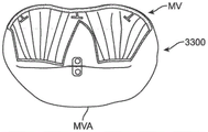
Fig. 33A and 33B illustrate another embodiment of a leaflet assisting device 3300 for a native mitral valve MV previously treated with a leaflet fixating device (in this case a mitral valve clip MC), wherein the leaflet assisting device 3300 is configured to be attached to the mitral valve annulus MVA parallel to the coaptation axis. As shown, the coaptation device 3300 can include two leaflets 3301 such that the two leaflets are each on one side of the leaflet retainer device. In some embodiments, the leaflet assisting device 3300 comprises only one leaflet 3301 for treating half of the coaptation. Fig. 33A illustrates the valve MV in diastole and fig. 33B illustrates the valve MV in systole.
Fig. 34 illustrates an embodiment of a leaflet accessory 3400, similar to the device illustrated in fig. 33B, including a direction sensitive central stiffener 3403 and two leaflets-a first leaflet 3401a and a second leaflet 3401B. The direction sensitive central stiffener 3403 may be similar to other direction sensitive stiffeners described herein, or vice versa (e.g., one side thereof may have multiple slices or spaces to promote bending in one direction and resist bending in the other, opposite direction).
Fig. 35 illustrates a cross-section of a mitral valve, wherein a semi-flexible leaflet assist device 3500 is placed over the posterior leaflet of the mitral valve (PML) such that it engages the anterior leaflet of the mitral valve (AML). The leaflet assist device 3500 is anchored along the mitral annulus and can be anchored by any of the methods described elsewhere herein. Dashed line 3501 represents the level of uppermost natural and/or expected flexion of the native leaflets when the valve is closed, described herein as the level of flexion. In the mitral valve, this level will be at or near the most atrial level of the annulus.
Such leaflet assist devices may include pericardium, artificial tissue, or other synthetic materials (i.e., Dacron). The leaflet aid 3500 includes a reinforcement perimeter 3530. The perimeter 3530 may be reinforced by stitching applied to the edges. In some embodiments, the reinforcement may be included in a suture applied to the edge, such as a nitinol wire. In some embodiments, leaflet assist device 3500 can include two layers and a suture around peripheral edge 3530 for attaching the two layers. Fig. 36 illustrates such a leaflet 3600 comprising two layers of pericardium stitched together at a reinforcing perimeter 3630.
Fig. 37 to 40 illustrate embodiments of a leaflet assisting device that enhances coaptation (as shown by coaptation area CA) by placing a patch or barrier at or near the level of flexion of the mitral valve. Typically, these devices will be placed such that they restrict the native leaflets from moving to a level at or below the level of flexion. These devices can be used in conjunction with or independent of the device of fig. 36 or other leaflet assisting devices described herein. These means may be attached screws, stapes, sutures or any other suitable means, including any means previously described herein.
Fig. 37 illustrates a leaflet assist device 3700 that includes a rectangular sheet 3710 placed directly below the level of flexion of the mitral valve. Such a device would limit the movement of the native and/or other mitral valve assist device to the level at which it is placed. As shown, the leaflet assistive device 3700 attachments 3720 are located at the 4 corners. Coaptation of the valve will be enhanced by forcing better coaptation and covering the area of poor coaptation.
The embodiments of fig. 38 and 39 illustrate alternative engagement devices 3800 and 3900, respectively, that include a volume filling assembly. The volume filling components shown here are spindle beads 3850 in fig. 38 and spherical beads 3950 in fig. 39. These volume filling assemblies are anchored to tethers 3840 and 3940 in the manner described elsewhere herein. In some embodiments, the volume filling assembly is an elastic balloon that is inflated in situ, in other embodiments, they may be self-inflating. The engaging means 3800 may also include a sheet 3810 and an attachment 3820, as in the apparatus 3700 described in fig. 37. Engagement device 3900 may also include attachment 3920, as in device 3700 depicted in fig. 37.
Fig. 40 illustrates an embodiment in which a leaflet 3600 as depicted in fig. 36 is used in conjunction with a leaflet assisting device 3700 as depicted in fig. 37.
Although the leaflet assisting devices described herein are generally described in the context of the mitral valve, they may be used to enhance the performance of any of the circulatory systems.
While preferred embodiments of the present invention have been shown and described herein, it will be readily understood by those skilled in the art that these embodiments are provided by way of example only. Numerous variations, changes, and substitutions will now occur to those skilled in the art without departing from the invention. It should be understood that various alternatives to the embodiments of the invention described herein may be employed in practicing the invention. It is intended that the following claims define the scope of the invention and that methods and structures within the scope of these claims and their equivalents be covered thereby.
Claims (60)
1. A method for promoting valve coaptation in a patient, the method comprising:
identifying a defective prosthetic leaflet implanted in a prosthetic valve of the patient; and
implanting a single prosthetic valve assist leaflet of a valve assist device over an upper surface of the defective prosthetic leaflet;
wherein the single valve auxiliary leaflet moves in unison with the defective prosthetic leaflet and engages a functional prosthetic valve leaflet opposite the defective prosthetic leaflet in response to blood flow through the prosthetic valve.
2. A method for promoting valve coaptation as in claim 1, wherein the prosthetic valve is implanted in a heart valve of the patient.
3. A method for promoting valve coaptation as in claim 2, wherein the heart valve is a mitral valve or an aortic valve.
4. A method for promoting valve coaptation as in claim 1, wherein the prosthetic valve is implanted in a venous valve of the patient.
5. A method for promoting valve coaptation as in claim 1, wherein the implanting comprises implanting the single prosthetic valve leaflet in an open surgical procedure.
6. A method for promoting valve coaptation as in claim 1, wherein the implanting comprises advancing the single prosthetic valve leaflet intravascularly.
7. A method for promoting valve coaptation as in claim 1, wherein the implanting comprises advancing the single prosthetic valve leaflet transseptally.
8. A method for promoting valve coaptation as in claim 1, wherein the implanting comprises transapically advancing the single prosthetic valve leaflet.
9. A method for promoting valve coaptation as in claim 1, wherein the implanting comprises self-expanding an anchor coupled to the single prosthetic valve leaflet within the prosthetic valve.
10. A method for promoting valve coaptation as in claim 9, wherein anchor is expanded to completely circumscribe the prosthetic valve.
11. A method for promoting valve coaptation as in claim 10, wherein anchor is expanded to partially circumscribe the prosthetic valve.
12. A method for promoting valve coaptation as in claim 10, wherein the anchor comprises one or more barbs that penetrate the prosthetic valve when the anchor is expanded.
13. A method for promoting valve coaptation as in claim 1, wherein the implanting comprises suturing an anchor coupled to the single prosthetic valve leaflet to the prosthetic valve.
14. A method for promoting valve coaptation as in claim 13, wherein anchors are sutured to completely circumscribe the prosthetic valve.
15. A method for promoting valve coaptation as in claim 1, wherein the anchors are sutured to partially circumscribe the prosthetic valve.
16. A method for promoting valve coaptation as in claim 1, wherein the valve assist device comprises a reinforcement element.
17. A method for promoting valve coaptation as in claim 1, wherein the reinforcement element is orientation sensitive.
18. A method for promoting valve coaptation in a patient, the method comprising:
identifying an annuloplasty ring positioned adjacent a prolapsed valve leaflet in a native valve of the patient; and
implanting a single prosthetic valve assist leaflet of a valve assist device over an upper surface of the prolapsed leaflet;
wherein the single valve auxiliary leaflet moves in unison with the prolapsed leaflet and engages a second valve leaflet opposite the prolapsed prosthetic leaflet in response to blood flow through the native valve.
19. The method for promoting valve coaptation as in claim 18, wherein the native valve is a heart valve.
20. A method for promoting valve coaptation as in claim 19, wherein the heart valve is a mitral valve or an aortic valve.
21. The method for promoting valve coaptation as in claim 18, wherein the native valve is a venous valve.
22. A method for promoting valve coaptation as in claim 18, wherein the implanting comprises implanting the single prosthetic valve leaflet in an open surgical procedure.
23. A method for promoting valve coaptation as in claim 18, wherein the implanting comprises advancing the single prosthetic valve leaflet intravascularly.
24. A method for promoting valve coaptation as in claim 18, wherein the implanting comprises advancing the single prosthetic valve leaflet transseptally.
25. A method for promoting valve coaptation as in claim 18, wherein the implanting comprises transapically advancing the single prosthetic valve leaflet.
26. The method for promoting valve coaptation of claim 18, wherein the implanting comprises self-expanding an anchor coupled to the single prosthetic valve leaflet within the native valve, thereby coupling the anchor to the annuloplasty ring.
27. The method for promoting valve coaptation of claim 26, wherein the anchor is expanded to completely circumscribe the annuloplasty ring.
28. The method for promoting valve coaptation of claim 26, wherein expanding the anchor partially circumscribes the annuloplasty ring.
29. The method for promoting valve coaptation of claim 26, wherein the anchor comprises one or more barbs that penetrate the annuloplasty ring as the anchor expands.
30. The method for promoting valve coaptation of claim 18, wherein the implanting comprises suturing an anchor coupled to the single prosthetic valve leaflet to the annuloplasty ring.
31. The method for promoting valve coaptation of claim 30, wherein suture anchors are used to completely circumscribe the annuloplasty ring.
32. The method for promoting valve coaptation of claim 18, wherein suture anchors are used to partially circumscribe the annuloplasty ring.
33. A method for promoting valve coaptation as in claim 18, wherein the valve assist device comprises a reinforcement element.
34. A method for promoting valve coaptation as in claim 33, wherein the reinforcement element is orientation sensitive.
35. A method for delivering a prosthetic valve coaptation assist device to a native valve site, the method comprising:
providing the prosthetic valve coaptation assist device having an anchor and a single prosthetic valve assist leaflet constrained within a delivery device;
advancing the delivery device toward the native valve site, the native valve site having a prosthetic valve implanted therein;
deploying the prosthetic valve coaptation assist device from the delivery device at the native valve site, wherein the prosthetic valve coaptation assist device has a connector coupled to the prosthetic valve to position the single prosthetic valve assist leaflet over an upper surface of a defective prosthetic leaflet of the prosthetic valve,
wherein the single valve auxiliary leaflet moves in unison with the defective prosthetic leaflet and engages a functional prosthetic valve leaflet opposite the defective prosthetic leaflet in response to blood flow through the prosthetic valve.
36. A method for delivering a prosthetic valve coaptation assist device as in claim 35, wherein the native valve is a heart valve.
37. A method for delivering a prosthetic valve coaptation assist device as in claim 35, wherein the heart valve is a mitral valve or an aortic valve.
38. A method for delivering a prosthetic valve coaptation assist device as in claim 35, wherein the native valve is a venous valve.
39. A method for delivering a prosthetic valve coaptation assist device as in claim 35, wherein the single prosthetic valve leaflet is advanced intravascularly.
40. A method for delivering a prosthetic valve coaptation assist device as in claim 35, wherein the single prosthetic valve leaflet is advanced transseptally.
41. A method for delivering a prosthetic valve coaptation assist device as in claim 35, wherein the single prosthetic valve leaflet is advanced transapically.
42. A method for delivering a prosthetic valve coaptation assist device as in claim 35, wherein the deploying comprises releasing the prosthetic valve coaptation assist device from a constraint such that the connector self-expands within the prosthetic valve to hold the single prosthetic valve leaflet in place over the defective prosthetic leaflet.
43. A method for delivering a prosthetic valve coaptation assist device as in claim 42, wherein the connector self-expands to fully circumscribe the prosthetic valve.
44. A method for delivering a prosthetic valve coaptation assist device as in claim 42, wherein the connector self-expands to partially circumscribe the prosthetic valve.
45. A method for delivering a prosthetic valve coaptation assist device as in claim 42, wherein the connector comprises one or more barbs that penetrate the prosthetic valve when the connector is self-expanding.
46. A method for delivering a prosthetic valve coaptation assist device as in claim 38, wherein the valve assist device comprises a reinforcing element.
47. A method for delivering a prosthetic valve coaptation assist device as in claim 46, wherein the reinforcing element is orientation sensitive.
48. A method for delivering a prosthetic valve coaptation assist device to a native valve site, the method comprising:
providing the prosthetic valve coaptation assist device having an anchor and a single prosthetic valve assist leaflet constrained within a delivery device;
advancing the delivery device toward the native valve site, the native valve site having an annuloplasty ring implanted therein;
deploying the prosthetic valve coaptation assist device from the delivery device at the native valve site, wherein the prosthetic valve coaptation assist device has a connector coupled to the annuloplasty ring to position the single prosthetic valve assist leaflet over an upper surface of a first native valve leaflet,
wherein the single valve assist leaflet moves in unison with the first native valve leaflet and engages a second native valve leaflet in response to blood flow through the valve.
49. A method for delivering a prosthetic valve coaptation assist device as in claim 48, wherein the native valve is a heart valve.
50. A method for delivering a prosthetic valve coaptation assist device as in claim 48, wherein the heart valve is a mitral valve or an aortic valve.
51. A method for delivering a prosthetic valve coaptation assist device as in claim 48, wherein the native valve is a venous valve.
52. A method for delivering a prosthetic valve coaptation assist device as in claim 48, wherein the single prosthetic valve leaflet is advanced intravascularly.
53. A method for delivering a prosthetic valve coaptation assist device as in claim 48, wherein the single prosthetic valve leaflet is advanced transseptally.
54. A method for delivering a prosthetic valve coaptation assist device as in claim 48, wherein the single prosthetic valve leaflet is advanced transapically.
55. A method for delivering a prosthetic valve coaptation assist device as in claim 48, wherein deploying comprises releasing the prosthetic valve coaptation assist device from restraint such that the connector self-expands within the annuloplasty ring to hold the single prosthetic valve leaflet in place over the first native valve leaflet.
56. The method for delivering a prosthetic valve coaptation assist device of claim 55, wherein the connector self-expands to fully circumscribe the annuloplasty ring.
57. The method for delivering a prosthetic valve coaptation assist device of claim 56, wherein the connector self-expands to partially circumscribe the annuloplasty ring.
58. The method for delivering a prosthetic valve coaptation assist device of claim 57, wherein the connector comprises one or more barbs that penetrate the annuloplasty ring when the connector is self-expanding.
59. A method for delivering a prosthetic valve coaptation assist device as in claim 48, wherein the prosthetic valve coaptation assist device comprises a reinforcing element.
60. A method for delivering a prosthetic valve coaptation assist device as in claim 59, wherein the reinforcing element is orientation sensitive.
Applications Claiming Priority (5)
| Application Number | Priority Date | Filing Date | Title |
|---|---|---|---|
| US201762455427P | 2017-02-06 | 2017-02-06 | |
| US62/455,427 | 2017-02-06 | ||
| US201762570336P | 2017-10-10 | 2017-10-10 | |
| US62/570,336 | 2017-10-10 | ||
| PCT/IB2018/000145 WO2018142217A2 (en) | 2017-02-06 | 2018-02-05 | Methods and systems for assisting or repairing prosthetic cardiac valves |
Publications (1)
| Publication Number | Publication Date |
|---|---|
| CN110891524A true CN110891524A (en) | 2020-03-17 |
Family
ID=62063101
Family Applications (1)
| Application Number | Title | Priority Date | Filing Date |
|---|---|---|---|
| CN201880023901.9A Pending CN110891524A (en) | 2017-02-06 | 2018-02-05 | Method and system for assisting or repairing a prosthetic heart valve |
Country Status (4)
| Country | Link |
|---|---|
| EP (1) | EP3576676A2 (en) |
| JP (1) | JP2020506007A (en) |
| CN (1) | CN110891524A (en) |
| WO (1) | WO2018142217A2 (en) |
Cited By (1)
| Publication number | Priority date | Publication date | Assignee | Title |
|---|---|---|---|---|
| WO2022206524A1 (en) * | 2021-03-31 | 2022-10-06 | 宁波健世科技股份有限公司 | Implantation instrument system capable of reducing diameter of loading tube |
Families Citing this family (5)
| Publication number | Priority date | Publication date | Assignee | Title |
|---|---|---|---|---|
| EP3007652A2 (en) | 2013-06-14 | 2016-04-20 | Hazu GmbH | Method and device for treatment of valve regurgitation |
| US11419719B2 (en) | 2017-02-06 | 2022-08-23 | Mtex Cardio Ag | Methods and systems for assisting or repairing prosthetic cardiac valves |
| WO2021024217A1 (en) | 2019-08-08 | 2021-02-11 | Mtex Cardio Ag | Leaflet coaptation-assistance devices |
| EP3912595B1 (en) * | 2020-05-19 | 2023-01-04 | AVVie GmbH | Implant for improving coaptation of an atrioventricular valve |
| CN113180889A (en) * | 2021-03-26 | 2021-07-30 | 启晨(上海)医疗器械有限公司 | Mitral valve replacement device and use method thereof |
Citations (5)
| Publication number | Priority date | Publication date | Assignee | Title |
|---|---|---|---|---|
| CN103338726A (en) * | 2011-01-28 | 2013-10-02 | 中峰医疗公司 | Coaptation enhancement implant, system and method |
| EP2863844A1 (en) * | 2012-06-22 | 2015-04-29 | Middle Peak Medical, Inc. | Device, system, and method for transcatheter treatment of valve regurgitation |
| WO2015195823A1 (en) * | 2014-06-18 | 2015-12-23 | Middle Peak Medical, Inc. | Mitral valve implants for the treatment of valvular regurgitation |
| CN105246431A (en) * | 2013-05-20 | 2016-01-13 | 托尔福公司 | Implantable heart valve devices, mitral valve repair devices and associated systems and methods |
| CN105451688A (en) * | 2013-06-14 | 2016-03-30 | 哈祖有限公司 | Method and device for treatment of valve regurgitation |
Family Cites Families (1)
| Publication number | Priority date | Publication date | Assignee | Title |
|---|---|---|---|---|
| CN104055600B (en) * | 2014-07-07 | 2016-02-03 | 宁波健世生物科技有限公司 | A kind of repair system for stoping valvular regurgitation with anchoring device |
-
2018
- 2018-02-05 EP EP18720349.2A patent/EP3576676A2/en not_active Withdrawn
- 2018-02-05 WO PCT/IB2018/000145 patent/WO2018142217A2/en unknown
- 2018-02-05 JP JP2019542599A patent/JP2020506007A/en active Pending
- 2018-02-05 CN CN201880023901.9A patent/CN110891524A/en active Pending
Patent Citations (6)
| Publication number | Priority date | Publication date | Assignee | Title |
|---|---|---|---|---|
| CN103338726A (en) * | 2011-01-28 | 2013-10-02 | 中峰医疗公司 | Coaptation enhancement implant, system and method |
| EP2863844A1 (en) * | 2012-06-22 | 2015-04-29 | Middle Peak Medical, Inc. | Device, system, and method for transcatheter treatment of valve regurgitation |
| CN104582637A (en) * | 2012-06-22 | 2015-04-29 | 中峰医疗公司 | Device, system, and method for transcatheter treatment of valve regurgitation |
| CN105246431A (en) * | 2013-05-20 | 2016-01-13 | 托尔福公司 | Implantable heart valve devices, mitral valve repair devices and associated systems and methods |
| CN105451688A (en) * | 2013-06-14 | 2016-03-30 | 哈祖有限公司 | Method and device for treatment of valve regurgitation |
| WO2015195823A1 (en) * | 2014-06-18 | 2015-12-23 | Middle Peak Medical, Inc. | Mitral valve implants for the treatment of valvular regurgitation |
Cited By (1)
| Publication number | Priority date | Publication date | Assignee | Title |
|---|---|---|---|---|
| WO2022206524A1 (en) * | 2021-03-31 | 2022-10-06 | 宁波健世科技股份有限公司 | Implantation instrument system capable of reducing diameter of loading tube |
Also Published As
| Publication number | Publication date |
|---|---|
| EP3576676A2 (en) | 2019-12-11 |
| WO2018142217A2 (en) | 2018-08-09 |
| JP2020506007A (en) | 2020-02-27 |
Similar Documents
| Publication | Publication Date | Title |
|---|---|---|
| US11419719B2 (en) | Methods and systems for assisting or repairing prosthetic cardiac valves | |
| US20200383776A1 (en) | Method and device for treatment of valve regurgitation | |
| US11793630B2 (en) | Apparatus and methods for implanting a replacement heart valve | |
| CN216365424U (en) | System for heart valve leaflet repair | |
| CN216417417U (en) | Valve repair device | |
| AU2012272855C1 (en) | Prosthetic heart valve devices and associated systems and methods | |
| US8252051B2 (en) | Method of implanting a prosthetic valve in a mitral valve with pulmonary vein anchoring | |
| EP1734872B1 (en) | Devices and systems for supporting tissue and/or structures within a hollow body organ | |
| CN110891524A (en) | Method and system for assisting or repairing a prosthetic heart valve | |
| US20100262232A1 (en) | Implantable scaffolding containing an orifice for use with a prosthetic or bio-prosthetic valve | |
| EP3154476A1 (en) | Two stage anchor and mitral valve assembly | |
| US10500038B1 (en) | Prosthetic mitral valve, and methods and devices for deploying the prosthetic mitral valve | |
| US20230025890A1 (en) | Transcatheter Valve To Treat Small Native Mitral Anatomy | |
| TW202224648A (en) | Systems and methods for heart valve leaflet repair |
Legal Events
| Date | Code | Title | Description |
|---|---|---|---|
| PB01 | Publication | ||
| PB01 | Publication | ||
| SE01 | Entry into force of request for substantive examination | ||
| SE01 | Entry into force of request for substantive examination | ||
| REG | Reference to a national code |
Ref country code: HK Ref legal event code: DE Ref document number: 40019927 Country of ref document: HK |
|
| WD01 | Invention patent application deemed withdrawn after publication | ||
| WD01 | Invention patent application deemed withdrawn after publication |
Application publication date: 20200317 |