CN110856251B - Terminal positioning method in ultra-dense network - Google Patents
Terminal positioning method in ultra-dense network Download PDFInfo
- Publication number
- CN110856251B CN110856251B CN201911062995.3A CN201911062995A CN110856251B CN 110856251 B CN110856251 B CN 110856251B CN 201911062995 A CN201911062995 A CN 201911062995A CN 110856251 B CN110856251 B CN 110856251B
- Authority
- CN
- China
- Prior art keywords
- base station
- positioning
- base stations
- subset
- terminal
- Prior art date
- Legal status (The legal status is an assumption and is not a legal conclusion. Google has not performed a legal analysis and makes no representation as to the accuracy of the status listed.)
- Active
Links
Images


Classifications
-
- H—ELECTRICITY
- H04—ELECTRIC COMMUNICATION TECHNIQUE
- H04W—WIRELESS COMMUNICATION NETWORKS
- H04W64/00—Locating users or terminals or network equipment for network management purposes, e.g. mobility management
- H04W64/003—Locating users or terminals or network equipment for network management purposes, e.g. mobility management locating network equipment
-
- H—ELECTRICITY
- H04—ELECTRIC COMMUNICATION TECHNIQUE
- H04B—TRANSMISSION
- H04B17/00—Monitoring; Testing
- H04B17/30—Monitoring; Testing of propagation channels
- H04B17/309—Measuring or estimating channel quality parameters
- H04B17/318—Received signal strength
- H04B17/327—Received signal code power [RSCP]
-
- H—ELECTRICITY
- H04—ELECTRIC COMMUNICATION TECHNIQUE
- H04B—TRANSMISSION
- H04B17/00—Monitoring; Testing
- H04B17/30—Monitoring; Testing of propagation channels
- H04B17/309—Measuring or estimating channel quality parameters
- H04B17/336—Signal-to-interference ratio [SIR] or carrier-to-interference ratio [CIR]
-
- H—ELECTRICITY
- H04—ELECTRIC COMMUNICATION TECHNIQUE
- H04W—WIRELESS COMMUNICATION NETWORKS
- H04W64/00—Locating users or terminals or network equipment for network management purposes, e.g. mobility management
- H04W64/006—Locating users or terminals or network equipment for network management purposes, e.g. mobility management with additional information processing, e.g. for direction or speed determination
Landscapes
- Engineering & Computer Science (AREA)
- Computer Networks & Wireless Communication (AREA)
- Signal Processing (AREA)
- Quality & Reliability (AREA)
- Physics & Mathematics (AREA)
- Electromagnetism (AREA)
- Mobile Radio Communication Systems (AREA)
- Position Fixing By Use Of Radio Waves (AREA)
Abstract
The invention discloses a terminal positioning method in an ultra-dense network, and belongs to the field of terminal positioning. The method comprises the steps that the terminal identifies visible base stations according to the signal quality of signals received by each base station; then arranging the visible base stations in a descending order according to SINR, and performing primary positioning by utilizing pseudo-range measurement results corresponding to the base stations arranged in front; then, selecting and grouping based on the geometric relationship to obtain a plurality of base station subsets, and screening the positioning base station subsets with better geometric distribution according to the horizontal precision factor; and finally, according to the positioning estimation result corresponding to each screened base station subset, selecting the positioning base station subset which is less influenced by non-line-of-sight by using a clustering algorithm to provide positioning service for the terminal. The terminal positioning method in the ultra-dense network provided by the invention can solve the problem that the OTDOA positioning technology has lower precision in a 5G ultra-dense network, and can be downward compatible with the existing multilateral positioning technology; in addition, the method can enhance the robustness and reliability of the positioning service.
Description
Technical Field
The invention relates to a terminal positioning method in an ultra-dense network, belongs to the field of terminal positioning, and particularly relates to a terminal positioning method in an ultra-dense network, and a positioning process and a positioning base station selection algorithm related to the terminal positioning method.
Background
Terminal location technology, which is a technology for estimating location parameters unknown to a user terminal based on given observation information and statistical information, is known as an important enabling technology of a fifth Generation (5th Generation,5G) mobile communication network. The application of the terminal positioning technology can provide diversified location-based services for users, such as unmanned driving, positioning navigation, wireless emergency services, mobile marketing and the like. On the other hand, terminal location technology may also assist the 5G network to enhance its performance in terms of scalability, delay and robustness.
Observable time difference of Arrival (OTDoA) is a technique for positioning a ue using the time difference of Arrival of downlink reference signals in a cellular network, and has been successfully applied in the LTE system, and is widely considered as a candidate positioning technique for a 5G network. However, in complex terrain environments such as dense cities, urban canyons and indoors, the positioning accuracy of the OTDoA technology is susceptible to non-line-of-sight propagation of signals, and the performance of the OTDoA technology cannot meet the requirement of a 5G network on positioning service.
An Ultra-dense Network (UDN) is one of typical coverage scenarios of a 5G Network, and aims to improve the carrying capacity of the 5G Network by dense deployment of a large number of heterogeneous base stations so as to meet the increasing demand of a large number of users on wireless ubiquitous services. Compared with a macro base station network, the dense base station deployment increases the number of positioning reference base stations visible for the user terminal, and reduces the average distance between the user terminal and the base station. However, base station deployment of UDNs is highly random, leading to uncertainty in the geometric topology. When the quality of the geometric distribution between the positioning reference base station and the user is poor, the ranging error will have a serious negative impact on the positioning accuracy of the OTDoA technique.
In view of the problems that the traditional OTDOA technology is weak in non-line-of-sight error inhibition capability and poor in positioning reference base station geometric distribution quality when applied to a 5G UDN, the novel terminal positioning method should make full use of the characteristics of the 5G UDN, overcome the difficulties encountered in a 5G network by the traditional OTDOA technology, and accordingly effectively improve the performance of positioning service.
Disclosure of Invention
The invention aims to provide a terminal positioning method for an ultra-dense network, which aims to solve the problem of low precision of an OTDOA positioning technology in a 5G ultra-dense network and enhance the robustness and reliability of positioning service.
The invention provides a terminal positioning method in an ultra-dense network, which comprises the following specific steps:
step one, a terminal identifies a base station visible to a user terminal in an ultra-dense network by measuring a signal to Interference plus Noise Ratio (SINR) of a downlink signal sent by each base station at the user terminal.
The invention selects the base station of which the SINR of the downlink reference signal at the user terminal is greater than the visibility judgment threshold as the positioning reference base station. The base stations are integrated into pt,iIs the transmission power, PL, of the base station i downlink reference signaliIs the path loss, p, from base station i to the user terminalnoiseIs the received noise power; j. the design is a squareiRepresenting a set of base stations sharing the same communication resource with base station i, the SINR of base station i can be represented as:

the base station visibility judgment threshold is SINRthrWhen the SINR isiSatisfies SINRi≥SINRthrWhen the base station i is determined to be a visible base station of the user terminal, that is, the user terminal may use the base station i as a positioning reference base station. The set of base stations visible to the user terminal is denoted as Collection
 The number of the elements N' is more than or equal to 3.
And step two, measuring the pseudo range corresponding to the visible base station identified and obtained in the step one, arranging the base stations in a descending order according to the SINR of the base stations, and performing primary positioning on the user terminal by using the pseudo range measurement result corresponding to the base station arranged in front.
It can be seen that a Time of arrival (ToA) measurement corresponding to the bs i, i.e. a pseudorange, can be represented as:

wherein r isiIs the euclidean distance between the user equipment and the base station i, Δ τ is the clock error,iis a delay measurement error caused by noise, interference, and non-line-of-sight propagation of the signal.
Let x be [ x, y ═ x]TAnd Ii=[xi,yi]TAre respectively provided withRepresenting two-dimensional coordinates of the user terminal and the base station i, the measured value of the signal time difference (RSTD) corresponding to the base station i and the base station j is represented as:

after RSTD observed values corresponding to at least 3 base stations (under the condition of two-dimensional positioning) are obtained, RSTD measured values corresponding to the base stations i and j are converted into distance difference measured values rhoi,jExpressed as the sum of the actual distance difference and the error term:
ρi,j=h(x)+i,j=c△ti,j+i,j
based on the measurement model shown in the formula, the position of the user terminal is estimated by using a weighted least square algorithm, and the primary iteration position of the user is Let the position after the k-1 iteration update be
 The kth iteration is then represented as:

with the base station 1 as a reference base station, RSTD measurement values are generated, wherein W is a diagonal matrix which is set according to the received signal SINR, and diagonal elements Wherein const is 1.1 × 10⁻⁴And B is the signal bandwidth;
 the specific expression is as follows:

make iteration update quantity When in use
 Judging the algorithm convergence, ending iteration and outputting the final estimated position
 Simultaneously noted as the initial estimated location x of the user terminal0。
And step three, calculating the relative altitude angle and the azimuth angle between the user terminal and each base station by using the initial estimation position obtained in the step two, and performing primary screening and grouping on the visible base stations identified in the step one according to the relative altitude angle and the azimuth angle to obtain a plurality of base station subsets.
In order to improve the geometric distribution quality of the positioning reference base station, the invention provides the following base station primary screening algorithm.
1) Calculating the initial estimated position x of the user0And collections Altitude angle alpha of middle base station nnAnd azimuth angle betan;
2) Selecting a base station n with a minimum altitude angle with the user*As reference nodes, i.e.
3) Setting M azimuth grouping reference angles, i belongs to {1, 1.. multidata, M }, and the base stations are grouped according to the difference value between each base station azimuth angle and three grouping reference azimuth angles, namely when the base stations belong to the group
 When the set is up, the base station n is divided into an ith group, i belongs to { 1., M };
4) if the number of base stations allocated to the ith group is zero, the number of base stations to which the ith group is allocated is increased The base stations are assigned again to the ith group until at least one base station is in each group, and the ith group contains a base station index set represented by
 Containing the number of elements Ni;
And step four, calculating horizontal Precision factors (HDOP) corresponding to the base station subsets obtained in the step three, and performing secondary base station screening on the base station subsets according to the HDOP.
The invention relates to a secondary base station screening strategy designed aiming at improving the geometric distribution quality of a positioning reference base station, which comprises the following steps.
1) From And i belongs to the base stations { 1.,. M }, and one base station is selected from the base stations to form a base station subset, namely each base station subset contains M base stations. The constituent set of base station subsets is denoted Sinit={sj},j∈{1,...,JinitNumber of subsets
 And calculates its corresponding horizontal precision factor,
 expressed as:

wherein the content of the first and second substances, is the Jacobian matrix of the positioning ranging equation with the subset of base stations sjPosition reference base station position I int=[xt,yt]T,(t∈sj) And user terminal position x ═ x, y]TIt is related. Initially estimating a position x of a user0As the user terminal location information, i.e. x ═ x0Then HDOP can be expressed as:

2) according to HDOP threshold HthrExcluding subsets of base stations with poor geometric distribution quality as sj∈SinitUpdate Sinit,JinitIs S*,J*。
And step five, calculating the positioning results corresponding to the base station subsets obtained after the secondary base station screening in the step four, and selecting the positioning base station subsets for providing the positioning service for the terminal by utilizing a clustering algorithm according to the obtained positioning results.
The invention screens the positioning base station subsets which are less influenced by NLoS through a clustering algorithm, and the specific steps are as follows.
1) Calculating S according to the positioning method in the step two*A position estimate corresponding to each subset of base stations and corresponding pseudorange measurements, represented as a set
2) Using K-Means (K-Means) clustering algorithm pairs Performing cluster analysis, and dividing the cluster into K (K is more than or equal to 4) cluster centers with the mass center of pk=[xk,yk]T,k∈{1,...,K};
3) Calculating the number n of objects contained in each clusterk,k∈{1,...,K};
4) Selecting the cluster centroid containing the largest number of objects
5) In that To select a distance
 Nearest estimated position
 Namely, it is
6) Selecting Corresponding subset s of base stations*As a subset of positioning reference base stations that ultimately provide positioning services for the user terminal.
And sixthly, providing the positioning service for the terminal by using the subset of the positioning base stations selected in the step five.
According to the base station selection strategy, the positioning base station subset s with good geometric distribution quality and less influence of NLoS is selected for the user terminal*And providing high-precision positioning service for the user according to the positioning method in the step two.
The method for positioning the terminal in the ultra-dense network has the advantages and the effects that the method can accurately select the positioning base station subset which is good in geometric distribution quality and less influenced by NLoS for the user terminal, and further improves the precision, the robustness and the reliability of positioning service.
Drawings
Fig. 1 is a flowchart of a terminal positioning method proposed by the present invention;
FIG. 2 is a flow chart of a method for base station selection based on azimuth and HDOP in accordance with the present invention;
FIG. 3 is a flow chart of a base station selection method based on a clustering algorithm according to the present invention;
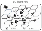
FIG. 4 is a schematic diagram of a 5G ultra-dense network to which the present invention is directed;
Detailed Description
The present invention will be described in further detail with reference to the accompanying drawings and examples.
The invention reduces the influence of non-line-of-sight propagation of signals and factors with non-ideal geometric distribution quality of the positioning base station on position estimation by optimally screening the base stations in the ultra-dense network, thereby improving the performance of positioning service.
The threshold SINR will be decided with the base station visibilitythrThe number of base stations used for initial positioning is 6, and the algorithm convergence judgment threshold is-10 dBthr=1×10⁻⁷Initial angle division threshold
 Increase in value
 The number of base stations M in the subset of base stations is 6, and the HDOP exclusion threshold HthrThe specific implementation of the invention is described in detail by taking 3 as an example and 4 as an example, and the overall flow of the method is shown in fig. 1.
The present invention first provides a method for judging the visibility of a base station, as shown in step 1.
Step 1: the user terminal measures the SINR of each base station when the SINRiSatisfies SINRi≥SINRthrI.e. SINRiAnd when the current base station is more than or equal to-10 dB, judging that the base station i is a visible base station of the user terminal, namely the user terminal can use the base station i as a positioning reference base station. The set of base stations visible to the user terminal is denoted as Collection
 The number of the elements N' is more than or equal to 3.
Obtaining a set of visible base stations of a terminal Then, the invention applies the method to OTDOA algorithm based on the strongest SINR to make initial positioning estimation, and the specific flow is step 2.1-step 2.2.
Step 2.1: and measuring the pseudo range corresponding to the visible base station identified in the step 1.
Step 2.2: arranging the visible base stations identified in the step 1 in a descending order according to SINR, selecting pseudo-range measurement results corresponding to 6 base stations before arrangement to carry out primary positioning on the user terminal, and performing iteration updating quantity when a weighted least square method is adopted Judging the algorithm convergence, ending iteration and outputting the final estimated position
 Simultaneously noted as the initial estimated location x of the user terminal0。
After the initial estimated position of the user is obtained, the method is applied to calculating the relative altitude angle and the azimuth angle between the user terminal and each base station, and the visible base stations identified in the step 1 are selected and grouped according to the relative altitude angle and the azimuth angle to obtain a plurality of base station subsets, and the specific flow is the step 3.1-the step 3.3.
Step 3.1: calculating the initial estimated position x of the user0And collections Altitude angle alpha of middle base station nnAnd azimuth angle betan(ii) a Selecting a base station n with a minimum altitude angle with the user*As reference nodes, i.e.
Step 3.2: setting 6 azimuth angle grouping reference angles according to eachGrouping the base stations by the difference between the base station azimuth and the three grouping reference azimuths, i.e. when When true, base station n is grouped into the ith group
Step 3.3: if the number of base stations allocated to the ith group is zero, the number of base stations allocated to the ith group is zero Increase of
 And reassigning base stations to the ith group until there is at least one base station in each group.
So far, the base stations in each obtained base station subset are distributed more uniformly, but further screening is needed. Calculating the corresponding horizontal precision factor HDOP, and screening the base station subset according to the HDOP, wherein the specific flow is step 4.1-step 4.2, and the overall flow of step 3 and step 4 is shown in FIG. 2.
Step 4.1: from Wherein each base station is selected to form a base station subset, i.e. each base station subset comprises 6 base stations. The constituent set of base station subsets is denoted Sinit={sj},j∈{1,...,JinitAnd calculates its corresponding horizontal precision factor,
step 4.2: according to HDOP threshold HthrExcluding subsets of base stations with poor geometric distribution quality as sj∈SinitUpdate Sinit,JinitIs S*,J*。
After the two base station screens of steps 3 and 4, a set S formed by the usable positioning base station subsets*In (1). Therefore, the quality of the geometric distribution of each positioning base station subset is better than a set threshold, and the influence of the geometric distribution on positioning is eliminated, namely the main negative influence factors of the positioning precision become estimation errors caused by NLoS measurement errors. As shown in fig. 3, the present invention screens such position estimation through a clustering algorithm, so as to obtain a positioning base station combination less affected by NLoS, and the specific flow is from step 5.1 to step 5.3:
step 5.1: calculating S according to the positioning method described in step 2.2*Each subset of base stations and corresponding position estimates for pseudorange measurements sj∈S*。
Step 5.2: using K-means clustering algorithm pairs Performing cluster analysis, and dividing the cluster into 4 cluster clusters with a cluster center of mass of pk=[xk,yk]T,k∈{1,...,4}。
Step 5.3: calculating the number n of objects contained in each clusterkK is equal to { 1.,. 4}, and the centroid of the cluster containing the largest number of objects is selected
Step 5.5: in that To select a distance
 Nearest estimated position
 Namely, it is
Step 5.6: selecting Corresponding subset s of base stations*As a subset of positioning reference base stations that ultimately provide positioning services for the user terminal.
The base station subset s for finally providing the positioning service for the user terminal through the base station selection strategy*The method has the characteristics of good geometric distribution quality and small influence of NLoS. Inventing a subset s of base stations*The method is applied to providing high-precision positioning service for the user terminal, and the specific flow is as follows:
step 6: according to the positioning method described in step 2.2, using s*And providing location services to the user terminal in response to the pseudorange measurements.
In summary, the terminal positioning method in the ultra-dense network provided by the present invention can more accurately select the positioning base station subset with good geometric distribution quality and less influence of NLoS for the user terminal, thereby improving the precision, robustness and reliability of the positioning service.
Claims (5)
1. A terminal positioning method in an ultra-dense network is characterized in that: the method comprises the following specific steps:
the method comprises the following steps that firstly, a terminal identifies base stations visible for a user terminal in the ultra-dense network by measuring the signal to interference plus noise ratio (SINR) of downlink signals sent by each base station at the user terminal;
step two, measuring pseudo ranges corresponding to the visible base stations identified and obtained in the step one, arranging the base stations in a descending order according to the SINR of the base stations, and performing primary positioning on the user terminal by using the pseudo range measurement results corresponding to the base stations arranged in front;
thirdly, calculating the relative altitude angle and the azimuth angle between the user terminal and each base station by using the initial estimation position obtained in the second step, and primarily screening and grouping the visible base stations identified in the first step according to the relative altitude angle and the azimuth angle to obtain a plurality of base station subsets;
step four, calculating the horizontal precision factor HDOP corresponding to each base station subset obtained in the step three, and carrying out secondary base station screening on the base station subsets according to the HDOP;
step five, calculating the positioning results corresponding to the base station subsets obtained after the secondary base station screening in the step four, and selecting the positioning base station subsets for providing the positioning service for the terminal by utilizing a clustering algorithm according to the obtained positioning results;
and sixthly, providing the positioning service for the terminal by using the positioning base station subset selected in the step five.
2. The method for positioning terminals in ultra-dense network as claimed in claim 1, wherein: specifically, the base station with the SINR of the downlink reference signal at the user terminal greater than the visibility decision threshold is selected as the positioning reference base station.
3. The method for positioning terminals in ultra-dense network as claimed in claim 1, wherein: the primary screening process of the base station in the third step is as follows:
1) calculating the initial estimated position x of the user0And collections Altitude angle alpha of middle base station nnAnd azimuth angle betan;
2) Selecting a base station n with a minimum altitude angle with the user*As reference nodes, i.e.
3) Setting M azimuth grouping reference angles, grouping the base stations according to the difference between each base station azimuth and the three grouping reference azimuths, i.e. when
 When the set is up, the base station n is divided into an ith group, i belongs to { 1., M };
4) if the number of base stations allocated to the ith group is zero, the number of base stations to which the ith group is allocated is increased The base stations are assigned again to the ith group until at least one base station is in each group, and the ith group contains a base station index set represented by
 Containing the number of elements Ni。
4. The method for positioning terminals in ultra-dense network as claimed in claim 1, wherein: the secondary base station screening in the fourth step comprises the following steps:
1) from Each base station is selected to form a base station subset, namely each base station subset contains M base stations; the constituent set of base station subsets is denoted Sinit={sj},j∈{1,...,JinitNumber of subsets
 And calculates its corresponding horizontal precision factor,
 expressed as:

wherein the content of the first and second substances, is the jacobian matrix of the positioning ranging equation,and a subset of base stations sjPosition reference base station position I int=[xt,yt]T,(t∈sj) And user terminal position x ═ x, y]T(ii) related; initially estimating a position x of a user0As the user terminal location information, i.e. x ═ x0Then HDOP is expressed as:

2) according to HDOP threshold HthrExcluding subsets of base stations with poor geometric distribution quality as Updating Sinit,JinitIs S*,J*。
5. The method for positioning terminals in ultra-dense network as claimed in claim 1, wherein: fifthly, screening the positioning base station subset which is less influenced by NLoS through a clustering algorithm, and specifically comprising the following steps:
1) calculating S according to the positioning method in the step two*A position estimate corresponding to each subset of base stations and corresponding pseudorange measurements, represented as a set
2) Using K-means clustering algorithm pairs Performing cluster analysis, and dividing the cluster into K (K is more than or equal to 4) cluster centers with the mass center of pk=[xk,yk]T,k∈{1,...,K};
3) Calculating the number n of objects contained in each clusterk,k∈{1,...,K};
4) Selecting the cluster centroid containing the largest number of objects
5) In that To select a distance
 Nearest estimated position
 Namely, it is
6) Selecting Corresponding subset s of base stations*As a subset of positioning reference base stations that ultimately provide positioning services for the user terminal.
Priority Applications (1)
| Application Number | Priority Date | Filing Date | Title |
|---|---|---|---|
| CN201911062995.3A CN110856251B (en) | 2019-10-31 | 2019-10-31 | Terminal positioning method in ultra-dense network |
Applications Claiming Priority (1)
| Application Number | Priority Date | Filing Date | Title |
|---|---|---|---|
| CN201911062995.3A CN110856251B (en) | 2019-10-31 | 2019-10-31 | Terminal positioning method in ultra-dense network |
Publications (2)
| Publication Number | Publication Date |
|---|---|
| CN110856251A CN110856251A (en) | 2020-02-28 |
| CN110856251B true CN110856251B (en) | 2020-10-27 |
Family
ID=69598459
Family Applications (1)
| Application Number | Title | Priority Date | Filing Date |
|---|---|---|---|
| CN201911062995.3A Active CN110856251B (en) | 2019-10-31 | 2019-10-31 | Terminal positioning method in ultra-dense network |
Country Status (1)
| Country | Link |
|---|---|
| CN (1) | CN110856251B (en) |
Families Citing this family (1)
| Publication number | Priority date | Publication date | Assignee | Title |
|---|---|---|---|---|
| CN112218236B (en) * | 2020-09-17 | 2022-04-15 | 中国电子科技集团公司第三十八研究所 | TDOA (time difference of arrival) positioning base station selection method and system based on multi-dimensional scoring |
Citations (2)
| Publication number | Priority date | Publication date | Assignee | Title |
|---|---|---|---|---|
| CN106961293A (en) * | 2017-04-10 | 2017-07-18 | 广东南方电信规划咨询设计院有限公司 | Wireless network distribution dense network resource allocation algorithm |
| CN108667653A (en) * | 2018-04-17 | 2018-10-16 | 东南大学 | Cached configuration method and device based on cluster in super-intensive network |
Family Cites Families (4)
| Publication number | Priority date | Publication date | Assignee | Title |
|---|---|---|---|---|
| CN105636192B (en) * | 2014-10-27 | 2019-02-26 | 中国移动通信集团设计院有限公司 | A kind of localization method and positioning device of terminal |
| US9813863B2 (en) * | 2015-08-06 | 2017-11-07 | Qualcomm Incorporated | Enhanced passive positioning with adaptive active positioning |
| CN105785412A (en) * | 2016-03-03 | 2016-07-20 | 东南大学 | Vehicle rapid optimizing satellite selection positioning method based on GPS and Beidou double constellations |
| CN109743777B (en) * | 2019-03-12 | 2020-04-28 | 北京邮电大学 | Positioning method, positioning device, electronic equipment and readable storage medium |
-
2019
- 2019-10-31 CN CN201911062995.3A patent/CN110856251B/en active Active
Patent Citations (2)
| Publication number | Priority date | Publication date | Assignee | Title |
|---|---|---|---|---|
| CN106961293A (en) * | 2017-04-10 | 2017-07-18 | 广东南方电信规划咨询设计院有限公司 | Wireless network distribution dense network resource allocation algorithm |
| CN108667653A (en) * | 2018-04-17 | 2018-10-16 | 东南大学 | Cached configuration method and device based on cluster in super-intensive network |
Also Published As
| Publication number | Publication date |
|---|---|
| CN110856251A (en) | 2020-02-28 |
Similar Documents
| Publication | Publication Date | Title |
|---|---|---|
| CN108490473B (en) | GNSS and UWB integrated unmanned aerial vehicle enhanced positioning method and system | |
| JP7108626B2 (en) | Method and system for locating a terminal in a wireless communication system | |
| CN101536591B (en) | Extended clustering for improved positioning | |
| RU2362213C2 (en) | Selection of navigation solution, used for establishing location of device in wireless communication system | |
| TWI438465B (en) | Method system and mobile unit for locating a geogprahical position using broadcast frequency modulation signals | |
| EP2422213B1 (en) | A method of improved positioning | |
| JP2001318136A (en) | Positioning method using weighted ridge regression | |
| CN103270801A (en) | Method of and system for locating the position of user equipment | |
| US9402188B2 (en) | Geo-location error correction for small cell placement | |
| CA2677087A1 (en) | System and method for optimizing location estimate of mobile unit | |
| US10422882B1 (en) | ARAIM subset selection method and system based on BeiDou constellation | |
| CN108702585A (en) | Mixed-fingerprint identification/OTDOA location technologies and system | |
| CN110856251B (en) | Terminal positioning method in ultra-dense network | |
| CN103180753A (en) | Method and devices for positioning information reporting | |
| Meng et al. | A study of network-side 5G user localization using angle-based fingerprints | |
| CN111238480B (en) | NLOS (non line of sight) identification method based on distance residual error and application of NLOS identification method in indoor positioning | |
| JP2016520801A (en) | Transmitter directional pruning to improve position determination | |
| KR100518964B1 (en) | A mobile location estimation system and method using area division and virtual area | |
| CN108924734A (en) | A kind of three-dimension sensor node positioning method and system | |
| Freedman et al. | Prediction based RSS fingerprinting for positioning and optimization in cellular networks | |
| WO2006113874A2 (en) | Method for leveraging diversity for enhanced location determination | |
| Juurakko et al. | Database correlation method with error correction for emergency location | |
| Benikovsky et al. | Localization in real GSM network with fingerprinting utilization | |
| Adeyelu et al. | An enhanced-received signal strength technique for estimating mobile station position in wireless sensor networks | |
| Leca et al. | Determining optimum base stations configuration for TOA localization inside celullar networks |
Legal Events
| Date | Code | Title | Description |
|---|---|---|---|
| PB01 | Publication | ||
| PB01 | Publication | ||
| SE01 | Entry into force of request for substantive examination | ||
| SE01 | Entry into force of request for substantive examination | ||
| GR01 | Patent grant | ||
| GR01 | Patent grant |