CN110797743B - Laser repetition rate multiplier and flat-top beam profile generator using mirrors and/or prisms - Google Patents
Laser repetition rate multiplier and flat-top beam profile generator using mirrors and/or prisms Download PDFInfo
- Publication number
- CN110797743B CN110797743B CN201911029361.8A CN201911029361A CN110797743B CN 110797743 B CN110797743 B CN 110797743B CN 201911029361 A CN201911029361 A CN 201911029361A CN 110797743 B CN110797743 B CN 110797743B
- Authority
- CN
- China
- Prior art keywords
- repetition rate
- cavity
- beam splitter
- pulse
- laser
- Prior art date
- Legal status (The legal status is an assumption and is not a legal conclusion. Google has not performed a legal analysis and makes no representation as to the accuracy of the status listed.)
- Active
Links
Images


Classifications
-
- H—ELECTRICITY
- H01—ELECTRIC ELEMENTS
- H01S—DEVICES USING THE PROCESS OF LIGHT AMPLIFICATION BY STIMULATED EMISSION OF RADIATION [LASER] TO AMPLIFY OR GENERATE LIGHT; DEVICES USING STIMULATED EMISSION OF ELECTROMAGNETIC RADIATION IN WAVE RANGES OTHER THAN OPTICAL
- H01S3/00—Lasers, i.e. devices using stimulated emission of electromagnetic radiation in the infrared, visible or ultraviolet wave range
- H01S3/10—Controlling the intensity, frequency, phase, polarisation or direction of the emitted radiation, e.g. switching, gating, modulating or demodulating
- H01S3/10038—Amplitude control
- H01S3/10046—Pulse repetition rate control
-
- G—PHYSICS
- G03—PHOTOGRAPHY; CINEMATOGRAPHY; ANALOGOUS TECHNIQUES USING WAVES OTHER THAN OPTICAL WAVES; ELECTROGRAPHY; HOLOGRAPHY
- G03F—PHOTOMECHANICAL PRODUCTION OF TEXTURED OR PATTERNED SURFACES, e.g. FOR PRINTING, FOR PROCESSING OF SEMICONDUCTOR DEVICES; MATERIALS THEREFOR; ORIGINALS THEREFOR; APPARATUS SPECIALLY ADAPTED THEREFOR
- G03F7/00—Photomechanical, e.g. photolithographic, production of textured or patterned surfaces, e.g. printing surfaces; Materials therefor, e.g. comprising photoresists; Apparatus specially adapted therefor
- G03F7/70—Microphotolithographic exposure; Apparatus therefor
- G03F7/70008—Production of exposure light, i.e. light sources
- G03F7/70025—Production of exposure light, i.e. light sources by lasers
-
- H—ELECTRICITY
- H01—ELECTRIC ELEMENTS
- H01S—DEVICES USING THE PROCESS OF LIGHT AMPLIFICATION BY STIMULATED EMISSION OF RADIATION [LASER] TO AMPLIFY OR GENERATE LIGHT; DEVICES USING STIMULATED EMISSION OF ELECTROMAGNETIC RADIATION IN WAVE RANGES OTHER THAN OPTICAL
- H01S3/00—Lasers, i.e. devices using stimulated emission of electromagnetic radiation in the infrared, visible or ultraviolet wave range
- H01S3/005—Optical devices external to the laser cavity, specially adapted for lasers, e.g. for homogenisation of the beam or for manipulating laser pulses, e.g. pulse shaping
- H01S3/0057—Temporal shaping, e.g. pulse compression, frequency chirping
-
- H—ELECTRICITY
- H01—ELECTRIC ELEMENTS
- H01S—DEVICES USING THE PROCESS OF LIGHT AMPLIFICATION BY STIMULATED EMISSION OF RADIATION [LASER] TO AMPLIFY OR GENERATE LIGHT; DEVICES USING STIMULATED EMISSION OF ELECTROMAGNETIC RADIATION IN WAVE RANGES OTHER THAN OPTICAL
- H01S3/00—Lasers, i.e. devices using stimulated emission of electromagnetic radiation in the infrared, visible or ultraviolet wave range
- H01S3/005—Optical devices external to the laser cavity, specially adapted for lasers, e.g. for homogenisation of the beam or for manipulating laser pulses, e.g. pulse shaping
- H01S3/0071—Beam steering, e.g. whereby a mirror outside the cavity is present to change the beam direction
-
- H—ELECTRICITY
- H01—ELECTRIC ELEMENTS
- H01S—DEVICES USING THE PROCESS OF LIGHT AMPLIFICATION BY STIMULATED EMISSION OF RADIATION [LASER] TO AMPLIFY OR GENERATE LIGHT; DEVICES USING STIMULATED EMISSION OF ELECTROMAGNETIC RADIATION IN WAVE RANGES OTHER THAN OPTICAL
- H01S3/00—Lasers, i.e. devices using stimulated emission of electromagnetic radiation in the infrared, visible or ultraviolet wave range
- H01S3/05—Construction or shape of optical resonators; Accommodation of active medium therein; Shape of active medium
- H01S3/08—Construction or shape of optical resonators or components thereof
- H01S3/08004—Construction or shape of optical resonators or components thereof incorporating a dispersive element, e.g. a prism for wavelength selection
-
- H—ELECTRICITY
- H01—ELECTRIC ELEMENTS
- H01S—DEVICES USING THE PROCESS OF LIGHT AMPLIFICATION BY STIMULATED EMISSION OF RADIATION [LASER] TO AMPLIFY OR GENERATE LIGHT; DEVICES USING STIMULATED EMISSION OF ELECTROMAGNETIC RADIATION IN WAVE RANGES OTHER THAN OPTICAL
- H01S3/00—Lasers, i.e. devices using stimulated emission of electromagnetic radiation in the infrared, visible or ultraviolet wave range
- H01S3/05—Construction or shape of optical resonators; Accommodation of active medium therein; Shape of active medium
- H01S3/08—Construction or shape of optical resonators or components thereof
- H01S3/08054—Passive cavity elements acting on the polarization, e.g. a polarizer for branching or walk-off compensation
-
- H—ELECTRICITY
- H01—ELECTRIC ELEMENTS
- H01S—DEVICES USING THE PROCESS OF LIGHT AMPLIFICATION BY STIMULATED EMISSION OF RADIATION [LASER] TO AMPLIFY OR GENERATE LIGHT; DEVICES USING STIMULATED EMISSION OF ELECTROMAGNETIC RADIATION IN WAVE RANGES OTHER THAN OPTICAL
- H01S3/00—Lasers, i.e. devices using stimulated emission of electromagnetic radiation in the infrared, visible or ultraviolet wave range
- H01S3/05—Construction or shape of optical resonators; Accommodation of active medium therein; Shape of active medium
- H01S3/08—Construction or shape of optical resonators or components thereof
- H01S3/08059—Constructional details of the reflector, e.g. shape
-
- H—ELECTRICITY
- H01—ELECTRIC ELEMENTS
- H01S—DEVICES USING THE PROCESS OF LIGHT AMPLIFICATION BY STIMULATED EMISSION OF RADIATION [LASER] TO AMPLIFY OR GENERATE LIGHT; DEVICES USING STIMULATED EMISSION OF ELECTROMAGNETIC RADIATION IN WAVE RANGES OTHER THAN OPTICAL
- H01S3/00—Lasers, i.e. devices using stimulated emission of electromagnetic radiation in the infrared, visible or ultraviolet wave range
- H01S3/05—Construction or shape of optical resonators; Accommodation of active medium therein; Shape of active medium
- H01S3/08—Construction or shape of optical resonators or components thereof
- H01S3/081—Construction or shape of optical resonators or components thereof comprising three or more reflectors
- H01S3/083—Ring lasers
-
- H—ELECTRICITY
- H01—ELECTRIC ELEMENTS
- H01S—DEVICES USING THE PROCESS OF LIGHT AMPLIFICATION BY STIMULATED EMISSION OF RADIATION [LASER] TO AMPLIFY OR GENERATE LIGHT; DEVICES USING STIMULATED EMISSION OF ELECTROMAGNETIC RADIATION IN WAVE RANGES OTHER THAN OPTICAL
- H01S3/00—Lasers, i.e. devices using stimulated emission of electromagnetic radiation in the infrared, visible or ultraviolet wave range
- H01S3/10—Controlling the intensity, frequency, phase, polarisation or direction of the emitted radiation, e.g. switching, gating, modulating or demodulating
- H01S3/10061—Polarization control
-
- H—ELECTRICITY
- H01—ELECTRIC ELEMENTS
- H01S—DEVICES USING THE PROCESS OF LIGHT AMPLIFICATION BY STIMULATED EMISSION OF RADIATION [LASER] TO AMPLIFY OR GENERATE LIGHT; DEVICES USING STIMULATED EMISSION OF ELECTROMAGNETIC RADIATION IN WAVE RANGES OTHER THAN OPTICAL
- H01S2301/00—Functional characteristics
- H01S2301/20—Lasers with a special output beam profile or cross-section, e.g. non-Gaussian
- H01S2301/203—Lasers with a special output beam profile or cross-section, e.g. non-Gaussian with at least one hole in the intensity distribution, e.g. annular or doughnut mode
-
- H—ELECTRICITY
- H01—ELECTRIC ELEMENTS
- H01S—DEVICES USING THE PROCESS OF LIGHT AMPLIFICATION BY STIMULATED EMISSION OF RADIATION [LASER] TO AMPLIFY OR GENERATE LIGHT; DEVICES USING STIMULATED EMISSION OF ELECTROMAGNETIC RADIATION IN WAVE RANGES OTHER THAN OPTICAL
- H01S2301/00—Functional characteristics
- H01S2301/20—Lasers with a special output beam profile or cross-section, e.g. non-Gaussian
- H01S2301/206—Top hat profile
Landscapes
- Physics & Mathematics (AREA)
- Electromagnetism (AREA)
- Engineering & Computer Science (AREA)
- Plasma & Fusion (AREA)
- Optics & Photonics (AREA)
- General Physics & Mathematics (AREA)
- Investigating Materials By The Use Of Optical Means Adapted For Particular Applications (AREA)
- Lasers (AREA)
- Testing Or Measuring Of Semiconductors Or The Like (AREA)
Abstract
The present application relates to a laser repetition rate multiplier and flat-top beam profile generator using mirrors and/or prisms. A repetition rate (pulse) multiplier includes one or more beam splitters and prisms forming one or more ring cavities having different optical path lengths that delay portions of the energy of each pulse. A series of input laser pulses circulate in the ring cavity and a portion of the energy of each pulse exits the system after traversing a shorter cavity path while another portion of the energy exits the system after traversing a longer cavity path and/or a combination of two cavity paths. By appropriate selection of the ring cavity optical path length, the repetition rate of the output series of laser pulses may be varied to a multiple of the input repetition rate. The relative energy of the output pulses can be controlled by selecting the transmission and reflection coefficients of the beam splitter. Some embodiments produce a time-averaged output beam profile that is substantially flat in one dimension.
Description
This application is a divisional application of the invention patent application entitled "laser repetition rate multiplier and flat-top beam profile generator using mirrors and/or prisms" filed on 18/6/2015 with application number "201580027977.5".
Related application
United states provisional patent application No. 62/015,01 entitled "Laser Pulse Multiplication Using Prisms" filed on 6/20/2014 of this application, is priority of and is incorporated by reference herein.
This application also claims priority from united states provisional patent application No. 62/038,471 entitled "Laser Repetition Rate Multiplier and Flat-Top Beam Profile Generators" (Laser Repetition Rate and Flat-Top Beam Profile Generators), filed on 8/18/2014, and which is incorporated herein by reference.
This application relates to U.S. patent application No. 13/487,075 entitled "Semiconductor Inspection And Metrology System Using Laser Pulse multiplexer" filed by Chuang et al on day 6/1 2012, U.S. patent application No. 13/711,593 entitled "Semiconductor Inspection And Metrology System Using Laser Pulse multiplexer" filed by Chuang et al on day 12/11 2012, And U.S. patent application No. 14/455,161 entitled "Split beam And Multi-Spot Flat Top Illumination (Split Gaussian beam And Multi-Spot-Top lighting) System for Surface Scanning Systems filed by Chuang et al on day 8/2014," scan System for us 14/455,161. All such applications are incorporated herein by reference.
Technical Field
The invention relates to reducing the optical peak power of laser pulses in the time domain and optionally homogenizing the beam power distribution in the spatial domain. This peak power reduction and homogenization system may use curved mirrors, beam splitters, waveplates, and prisms to produce an optimized pulse repetition rate multiplier with a flat-top spatial power distribution profile. The invention is particularly useful in semiconductor inspection and metrology systems.
Background
The illumination requirements for inspection and metrology are generally best met by Continuous Wave (CW) light sources. The CW light source has a constant power level, which allows images or data to be acquired continuously. However, at many wavelengths of interest, especially Ultraviolet (UV) wavelengths, CW light sources with sufficient luminosity (power per unit area per unit solid angle) are not available, expensive, or reliable. If the pulsed laser is the only available or cost-effective light source with sufficient time-averaged luminosity at the wavelength of interest, it is optimal to use a laser with a high repetition rate and a wide pulse width. The higher the pulse repetition rate, the lower the instantaneous peak power per pulse for the same time-averaged power level. The lower peak power of the laser pulse results in less damage to the optics and to the sample or wafer being measured, since most damage mechanisms are non-linear and strongly depend on the peak power rather than the average power.
In inspection and metrology applications, an additional advantage of increasing the repetition rate is that more pulses are collected per data acquisition or per pixel, resulting in better averaging of the inter-pulse variations and improved signal-to-noise ratio. Furthermore, for fast moving samples, a higher pulse rate may result in better sampling of the sample position over time, since the distance moved between each pulse is smaller.
The repetition rate of the laser subsystem may be increased by improving the lasing medium, the pump system, and/or its drive electronics. Unfortunately, modifying a UV laser that has been operated at a predetermined repetition rate may require a significant investment of time and money to improve one or more of its constituent elements, and the repetition rate may be improved only marginally. Further, increasing the repetition rate of the fundamental laser light in the UV laser light decreases the peak power of the fundamental laser light. This reduces the efficiency of the frequency conversion, which must be a non-linear procedure, and thus makes it difficult to generate high average UV power levels.
In many inspection applications, a flat or uniform (rather than Gaussian) illumination profile is desired. Spatially uniform illumination across the sample results in a more uniform signal-to-noise ratio across the illumination area and a higher dynamic range compared to non-uniform illumination. While incoherent light sources may be able to more easily produce uniform illumination than the gaussian profile of a laser, such light sources have a wider bandwidth (complicating the optical design due to chromatic aberration) and lower power density (reducing the signal-to-noise ratio) than the laser can provide. One known way to achieve an approximately flat profile from a Gaussian laser beam is to crop the Gaussian tail (Gaussian tail) and use only the central region of the beam (close to the peak). The method is easy to apply; however, if a moderately flat profile is desired, a large portion of the laser power is clipped and wasted. For example, if the maximum intensity change in the illumination needs to be about 10%, about 65% of the power is wasted, and a 20% change needs to waste about 50% of the power.
Therefore, a practical, inexpensive technique for operating on the output of UV lasers is needed to improve the repetition rate of the lasers. Furthermore, it may be advantageous if the optical subsystem that increases the repetition rate can be compact so that it can be easily incorporated into a system without taking up much space. Still further, there is a need for a repetition rate multiplier that can produce an approximately flat output profile while adding little additional components to the repetition rate multiplier, thus saving space and minimizing optical power loss.
Disclosure of Invention
A system for inspecting or measuring a sample is described. Such a system includes an illumination source, a device configured to perform light detection, optics configured to direct light from the illumination source to the sample and to direct light output, reflection, or transmission from the sample to a sensor. Notably, the illuminating body includes a pulsed laser emitting Ultraviolet (UV) wavelengths (i.e., wavelengths shorter than about 400 nm) and a repetition rate multiplier that multiplies a repetition rate of pulses from the pulsed laser. The repetition rate multiplier increases the number of laser pulses per unit time and decreases the peak power of each laser pulse. The reduction in peak power reduces or eliminates damage to the system optics or the sample being inspected or measured and allows a higher average laser power level to be used for a given damage threshold, thus improving the signal-to-noise ratio and/or speed of inspection or measurement. Multiplying the repetition rate after generation of the UV harmonics maintains the efficiency of UV harmonic conversion because the peak power of the laser pulses is not reduced in the harmonic conversion chain.
Inspection and measurement systems incorporating repetition rate multipliers as described herein are particularly useful at deep uv (duv) wavelengths (i.e., wavelengths shorter than about 300 nm) and vacuum uv (vuv) wavelengths (i.e., wavelengths shorter than about 190 nm), since many different types of materials can be rapidly damaged at high peak power levels of such wavelengths.
The sample may be supported by a stage that moves the sample relative to the optics during the inspection or measurement.
The exemplary inspection or measurement system may include one or more illumination paths that illuminate the sample from different angles of incidence and/or different azimuthal angles and/or using different wavelengths and/or polarization states. The exemplary inspection or measurement system may include one or more collection paths that collect light reflected or scattered by the sample in different directions and/or are sensitive to different wavelengths and/or to different polarization states.
The inspection and measurement system incorporating the repetition rate multiplier may be further configured to generate a time-averaged spatially uniform beam profile (i.e., a flat-top profile). The inspection or measurement system described herein incorporating a multiplier and a flat-top profile generator provides twice or more doubling of the laser repetition rate and a more uniform time-averaged beam profile using a small number of optical components in compact space. The inspection and metrology system described herein enables the use of higher average laser power, resulting in higher processing power, better signal quality, and more efficient use of laser energy.
Methods and systems for multiplying the repetition rate of a pulsed laser are described. Such methods and systems split an input laser pulse into multiple pulses separated in time in order to multiply the laser repetition rate by integer multiples of, for example, 2, 3, or 4. The input pulse is split into two such that part of the pulse continues and part of the pulse enters the ring cavity. After traversing at least one section of the ring cavity, the pulse is again split and a portion of the pulse exits the ring cavity and continues partially in the ring cavity. The repetition rate multiplier may be further configured to generate a time-averaged output profile that is approximately flat in one dimension and substantially gaussian in a vertical dimension. The repetition rate multiplier may include a flat mirror, a curved mirror, a polarizing beam splitter, a wave plate, a beam compensator, and/or a lens.
In one exemplary embodiment, an input laser pulse is split into two by a waveplate and a polarizing beam splitter. One portion of the input laser pulse is directed around a short annular cavity loop and another portion is directed around a long annular cavity loop. In its return to the input/output coupler (which may comprise a polarizing beam splitter), the pulse encounters another waveplate that determines the portion of the pulse energy that exits the cavity. The remainder of the pulse energy traverses the cavity again.
In one exemplary embodiment, the short and long cavity loop lengths are set at 1/3 and 2/3, respectively, that are spatially separated between the input laser pulses such that the output pulses will be delayed in time by an integer multiple of 1/3, 2/3, or 1/3 of the inter-pulse period. Such delayed pulses form a pulse train having a repetition rate that is three times the repetition rate of the original input laser pulses. The orientation and retardation of the two waveplates may be selected such that the output pulses have substantially equal inter-pulse energies.
In another exemplary embodiment, where the repetition rate can also be tripled, two mirrors form a ring cavity and two beam splitters are placed in between. Each time a pulse passes through the beam splitter, it splits into two pulses; one of the pulses passes directly while the other is deflected. Using these two beam splitters, some pulses traverse the longer cavity loop and others traverse the shorter cavity loop. In one exemplary embodiment, the shorter loop has a path length approximately equal to about 1/3 for the original input inter-pulse separation, and the longer loop path length is about 2/3 for the inter-pulse separation. In this embodiment, such output pulses form a pulse train having a repetition rate that is three times the repetition rate of the original input pulses. By appropriate selection of mirror curvature, mirror separation and beamsplitter reflectivity, the output pulses can have substantially equal inter-pulse energies.
In one embodiment, two beam compensators comprising flat plates are placed in the cavity to substantially compensate for the displacement in the beam path caused by the beam splitter such that the beams are reflected from a mirror in a pattern substantially symmetric around the cavity axis. In another embodiment, one (or both) beam compensators are replaced by a prism (or prisms) that substantially compensate for the displacement in the beam path of the one (or both) beam splitters. In yet another embodiment, no prism or beam compensator is used, and the beam splitters are positioned such that each compensates for beam displacement caused by the other.
In yet another exemplary embodiment, a flat mirror and prism are inserted into the optical path within the cavity to form a secondary cavity loop between the same pair of curved mirrors having a loop length of about half the length of the primary cavity loop. The master cavity loop may double the pulse repetition rate if the master cavity loop length is set to about half the original input inter-pulse separation. The pulses exiting the primary cavity loop enter the secondary cavity loop, which has a length of about half the length of the primary cavity loop, thus doubling the pulse repetition rate again, resulting in an output pulse repetition rate four times the repetition rate of the input laser light.
Some embodiments use a prism, such as an isosceles triangular prism or Dove (Dove) prism, to double the number of round trips the beam makes within the cavity. The two cavity routes produce two parallel output beams. The offset between these two beams may be selected such that they overlap to form a time-averaged spatially approximately flat-top beam profile.
In one embodiment, a 2x pulse multiplier scheme is used as the basis for flat-top profile generation. In another embodiment, a 3x pulse multiplier is used as the basis for flat top profile generation. In yet another embodiment, the 4x pulse multiplier scheme described above is used as a basis for flat-top profile generation. This embodiment can produce four parallel beams with a predetermined power ratio therebetween. By selecting the separation between the beams and the power ratio therebetween, a wider and flatter time-averaged beam profile can be achieved. Any of such repetition rate multipliers that produce an approximately flat-top profile may comprise a beam compensator and/or a prism.
In one embodiment, the ring cavity comprises a pair of orthogonal mirrors. In another embodiment, the ring cavity comprises prisms that achieve high reflectivity using total internal reflection. With the proper prism design, the ring cavity using the prism can achieve low loss without the need for a high reflectivity coating. High reflectivity coatings can be easily damaged by high intensity laser pulses (especially at short wavelengths), so many of the methods and systems described herein can have longer operating lifetimes and/or lower maintenance costs (especially when used to multiply the repetition rates of DUV and VUV lasers) compared to other ring cavities.
In one embodiment, one or more prisms in the ring cavity are designed such that the angle of incidence of the laser beam entering and exiting the prisms is close to the Brewster's angle and the laser beam is substantially polarized with respect to the prism entrance and exit surfaces P, such that losses due to reflection remain small without the use of any anti-reflection (AR) coatings. The AR coating can be easily damaged by high intensity laser pulses (especially at short wavelengths), so this embodiment can have a longer operating life and/or lower maintenance costs (especially when used to multiply the repetition rate of DUV and VUV lasers) than a ring cavity using AR coatings.
In one embodiment, the brewster cut is for beam polarization orientation prisms located in the same ring cavity plane, while in another embodiment, the brewster cut is for beam polarization orientation prisms perpendicular to the ring cavity plane.
In one embodiment, the beam is totally internally reflected twice in a single prism of appropriate design. This prism can replace both folding mirrors in the ring cavity, and thus reduce the total number of components and simplify the process of aligning the ring cavity.
In one embodiment, right angle prisms are used in the ring cavity. It reflects the beam twice, sending it back in the opposite direction while also shifting it in space. This unique feature of the right angle prism results in the flexibility to multiply the effective cavity length by simply rotating the right angle prism to a particular angle. For example, two ring cavities may be constructed to have similar physical lengths, but one has an optical path length that is an integer multiple (e.g., 2 times) of the optical path length of the other, so that the two ring cavities can be connected in series, so as to multiply the pulse repetition rate by a large factor, which then can be conveniently achieved in a single ring cavity.
In a preferred embodiment, the portion of the energy of each input laser pulse directed into the ring cavity is controlled by selecting the angle of incidence and polarization with respect to the surface to achieve the desired reflection and transmission coefficients. This has the advantage of avoiding the need for any coating on the surface and thus the possibility of avoiding coating damage caused by the peak power density of the laser pulses, which can be problematic especially when the laser repetition rate multiplier is used with deep UV or vacuum UV lasers having an average power of several hundred mW or more. Such lasers are increasingly needed in semiconductor inspection and metrology systems in order to achieve the desired sensitivity and signal-to-noise ratio when inspecting or measuring features having dimensions of about 100nm or less.
In a preferred embodiment, one or more lenses are used within the annular cavity to re-image each laser pulse so that it remains about the same shape and size each time it traverses the cavity. One embodiment uses a brewster angle lens without a coating to refocus each laser pulse, thus avoiding the risk of coating damage.
In a preferred embodiment, two or more of the above-described features are combined in one laser repetition rate multiplier. For example, in one preferred embodiment, the laser repetition rate multiplier comprises a ring cavity comprising three uncoated prisms, wherein the laser beam inside the cavity is substantially p-polarized with respect to the surface of the prisms. Both of the prisms use total internal reflection to efficiently circulate the laser beam within the annular cavity. The third prism has a surface oriented such that the laser beam is approximately s-polarized relative to the surface and the input pulses are incident at selected angles such that a desired portion of each input pulse is directed into the ring cavity.
Wafer inspection systems, patterned wafer inspection systems, photomask inspection systems, and metrology systems incorporating laser pulse multipliers are described. The compact size of the laser pulse multiplier described herein makes it relatively easy to incorporate into inspection and metrology systems. The use of uncoated optics in the laser pulse multiplier allows the inspection and metrology system to operate with high power deep UV lasers without performance degradation or maintenance issues due to coating damage.
Drawings
FIG. 1 illustrates an exemplary inspection or measurement system incorporating a pulsed laser and a laser pulse repetition rate multiplier, which may also be configured as a flat-top profile generator.
Fig. 2A and 2B illustrate a dark-field inspection system incorporating a repetition rate multiplier (which may also be configured as a flat-top profile generator).
Fig. 3 illustrates an inspection system configured to detect particles or defects on a sample using normal and oblique illumination beams, which may also benefit from incorporating a repetition rate multiplier (which may also be configured as a flat-top profile generator).
FIG. 4 is an exemplary catadioptric imaging system configured as an inspection system with bright-field and dark-field inspection modes and that may advantageously incorporate a repetition rate multiplier, which may also be configured as a flat-top profile generator.
Fig. 5 illustrates an exemplary repetition rate multiplier that produces an output pulse train having a pulse repetition rate that is three times the repetition rate of the input pulses.
Fig. 6 illustrates another exemplary repetition rate multiplier embodiment that also produces an output pulse train having a repetition rate that is three times the repetition rate of the input pulses.
Fig. 7A and 7B illustrate an exemplary repetition rate multiplier similar to that shown in fig. 6, but without the use of a beam compensator.
Fig. 8 illustrates an exemplary repetition rate multiplier that produces an output pulse train having a repetition rate that is four times the repetition rate of the input pulses.
Fig. 9 illustrates an exemplary 2x pulse repetition rate multiplier that uses an isosceles triangular prism instead of a plate beam compensator.
Fig. 10A and 10B illustrate features of an isosceles triangular prism, including spatial sequences of displaced and inverted beams.
Fig. 11A illustrates an exemplary embodiment of generating a flat-topped output beam profile by displacing the input beam illustrated in fig. 9.
FIG. 11B illustrates another exemplary embodiment of generating a flat-top profile by displacing the prism toward the cavity axis.
Fig. 12 illustrates a flat top profile formed by two partially overlapping gaussian beams.
Fig. 13 illustrates an exemplary flat-top profile generator based on the 3x pulse repetition rate multiplier scheme shown in fig. 6, wherein at least one slab compensator is replaced by a prism.
FIG. 14A illustrates an exemplary flat-top profile generator based on the 3x pulse repetition rate multiplier scheme shown in FIG. 7A.
FIG. 14B illustrates another exemplary flat-top profile generator based on the 3x pulse repetition rate multiplier scheme shown in FIG. 7B.
FIG. 15A illustrates another exemplary flat-top profile generator based on the 4x pulse repetition rate multiplier scheme shown in FIG. 8.
FIG. 15B illustrates an exemplary flat top profile produced by the design shown in FIG. 15A.
16A and 16B are front and side views showing a 2x pulse repetition rate multiplier based generator according to another embodiment.
16C and 16D are front and top views illustrating a 2X/4X pulse repetition rate multiplier based generator according to another embodiment.
Fig. 17 illustrates an exemplary repetition rate multiplier with 2 right angle prisms and a beam splitter.
Fig. 18 illustrates another exemplary repetition rate multiplier similar to fig. a but with one of the prisms rotated 90 deg. to double the delay time of the laser pulse within a given distance between the prisms.
19A, 19B, and 19C are simplified diagrams illustrating how the ring cavity length can be changed to different integer multiples of the physical cavity length by rotating one of a cube-corner mirror pair or prism according to one embodiment.
Fig. 20 illustrates one possible embodiment of using two chambers of similar external dimensions to produce a pulse train having a repetition rate that is 4 times the repetition rate of the input pulse train.
FIG. 21 illustrates one exemplary lens configuration used in a pulse repetition rate multiplier to maintain the laser beam quality of each pulse as it travels around the ring cavity.
FIG. 22 illustrates a lens configuration similar to FIG. 21 that maintains laser beam quality in a ring cavity that rotates one of the prisms relative to the other.
FIG. 23 illustrates an alternative exemplary lens configuration used in a pulse repetition multiplier to maintain its laser beam quality as each pulse travels around the ring cavity.
FIG. 24 illustrates another exemplary lens configuration used in a pulse repetition rate multiplier to maintain laser beam quality using cylindrical lenses with laser light incident on each lens at an angle approximately equal to the Brewster angle.
Fig. 25A and 25B illustrate two exemplary pulse repetition rate multipliers with a special prism design that combines the beam splitter function into one of the prisms. Both repetition rate multipliers may use brewster angle prisms for recycling light in the cavity. The repetition rate multiplier of fig. 25B can use all uncoated optics to avoid the possibility of coating damage due to high intensity deep UV laser pulses.
Fig. 26A and 26B illustrate an exemplary repetition rate multiplier similar to that of fig. 25A, but with one of the prisms rotated 90 ° to double the pulse delay time.
Fig. 27A and 27B illustrate an exemplary repetition rate multiplier using 3 prisms without coatings and without separate beam splitters. As with all other embodiments using uncoated optics, this repetition rate multiplier is particularly suitable in the deep UV because it avoids the possibility of coating damage due to laser pulses.
28, 28A, 28B, and 28C illustrate details of the design of the first prism of FIG. 27A.
Fig. 29A and 29B are graphs illustrating Fresnel (Fresnel) reflection as a function of incident angle for both external and internal reflection. The angle of incidence used in one embodiment of the first prism of fig. 27A is shown.
Fig. 30, 30A and 30B illustrate details of the design of the second prism of fig. 27A.
Fig. 31, 31A, 31B and 31C illustrate details of the design of the third prism of fig. 27A.
Fig. 32A and 32B illustrate alternative exemplary repetition rate multipliers using two prisms and beam splitters or one prism, one mirror, and one beam splitter.
FIG. 33 illustrates an exemplary 4x repetition rate multiplier comprising two ring cavities similar to that shown in FIG. 32A, with one of the ring cavities having its prism rotated 90 in order to double its effective cavity length.
Detailed Description
Improved illumination systems for semiconductor inspection and measurement systems are described herein. The following description is presented to enable one of ordinary skill in the art to make and use the invention as provided in the context of a particular application and its requirements. Various modifications to the described embodiments will be readily apparent to those skilled in the art, and the generic principles defined herein may be applied to other embodiments. Thus, the present invention is not intended to be limited to the particular embodiments shown and described, but is to be accorded the widest scope consistent with the principles and novel features disclosed herein.
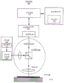
FIG. 1 illustrates an exemplary inspection system 100 configured to inspect or measure a sample 108, such as a wafer, reticle, or photomask. Sample 108 is placed on stage 112 to facilitate movement of different regions of sample 108 under the optics. Stage 112 may include an X-Y stage or an R-theta stage. In some embodiments, stage 112 may adjust the height of sample 108 during inspection to maintain focus. In other embodiments, the objective lens 105 may be adjusted to maintain focus.
The illumination source 102 includes one or more pulsed lasers and a repetition rate multiplier as described herein. The illumination source 102 may emit DUV and/or VUV radiation. The optics 103 (including the objective lens 105) directs the radiation towards the sample 108 and focuses it on the sample 108. The optics 103 may also include mirrors, lenses and/or beam splitters (not shown in detail for simplicity). Light reflected or scattered from sample 108 is collected, directed, and focused by optics 103 onto detector 106 within detector assembly 104.
The detector 106 may include a two-dimensional array sensor or a one-dimensional line sensor. In one embodiment, the output of the detector 106 is provided to a computing system 114, and the computing system 114 analyzes the output. Computing system 114 is configured by program instructions 118 that may be stored on carrier medium 116.
The illumination source 102 includes a pulsed laser 119 and a repetition rate multiplier 120. In one embodiment, the illumination source 102 may also comprise a continuous source, such as an arc lamp, a laser-excited plasma light source, or a CW laser.
One embodiment of the inspection system 100 illuminates lines on the sample 108 and collects scattered and/or reflected light in one or more dark-field and/or bright-field collection channels. In this embodiment, the detector 106 may include a line sensor or an electron bombarded line sensor. In this embodiment, the repetition rate multiplier 120 within the illumination source 102 may be configured to produce a flat-top profile in order to effectively produce a substantially uniform line illumination.
Another embodiment of the inspection system 100 illuminates a plurality of points on the sample 108 and collects scattered and/or reflected light in one or more dark-field and/or bright-field collection channels. In this embodiment, the detector 106 may include a two-dimensional array sensor or an electron bombarded two-dimensional array sensor.
Additional details of various embodiments of inspection system 100 are described in the following: U.S. patent application No. 13/554,954 entitled "Wafer Inspection System" (published 7/9.2012), U.S. patent No. 7,957,066 entitled "Split Field Inspection System Using Small Catadioptric Objectives" published 6/7.2011, U.S. patent No. 7,345,825 entitled "Beam Delivery System For Laser Dark Field Illumination in Catadioptric Optical System" (published 3/18.2008), U.S. patent No. 7,345,825 entitled "published 12/7.1999," Ultra-Wide-Range Zoom capable UV Microscope Imaging System "(published 12/7.999) entitled" Ultra-Wide-area Zoom capable UV Microscope Imaging System "(published 5 published by" published two-dimensional Inspection System With Imaging Surface Inspection System "(published 4 published three-dimensional Inspection System) published by" published Inspection System Using two-dimensional Inspection System With Imaging Surface consisting of Wafer Inspection System "(published 4: 5) published by" published three-dimensional Inspection System Using microscopic Imaging System "(published 4: published 3/7/3.4) and published by" published two-dimensional Inspection System Using Microscope Imaging System "published by" published three-dimensional Inspection System Us patent No. 7,525,649 of Laser Line Illumination With Two Dimensional Imaging) ". All such patents are incorporated herein by reference.
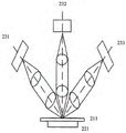
Fig. 2A and 2B illustrate aspects of a dark field inspection system 200 incorporating the repetition rate multiplier and/or repetition rate multiplier methods described herein, according to other exemplary embodiments of the invention. In fig. 2A, the illumination optics 201 includes a laser system 220, the laser system 220 generating light 202, the light 202 being focused by a mirror or lens 203 into a line 205 on the surface of a wafer or photomask (sample) 211 being inspected. Collection optics 210 uses lenses and/or mirrors 212 and 213 to direct light scattered from line 205 to sensor 215. The optical axis 214 of the collection optics 210 is not in the illumination plane of line 205. In some embodiments, the optical axis 214 is about perpendicular to the line 205. Sensor 215 comprises an array sensor, such as a linear array sensor. The laser system 220 incorporates one or more of the repetition rate multipliers and/or repetition rate multiplication methods described herein. The laser system 220 may be configured to efficiently generate a flat top profile in accordance with embodiments of the present invention such that the time-averaged light intensity along the line 205 may be substantially uniform.
Fig. 2B illustrates one embodiment of a plurality of dark field collection systems 231, 232, and 233, each substantially similar to collection optics 210 of fig. 2A. Collection systems 231, 232, and 233 may be used in combination with illumination optics substantially similar to illumination optics 201 of fig. 2A. The sample 211 is supported on a stage 221, and the stage 221 moves the area to be inspected under the optics. Stage 221 may comprise an X-Y stage or an R-theta stage that is preferably moved substantially continuously during the inspection to inspect large areas of the sample to minimize dead time.
More details of the inspection system according to the embodiment illustrated in fig. 2A and 2B are described in the following: us patent 7,525,649 entitled "Surface inspection System using laser line illumination with two-dimensional imaging" issued on day 28, 4.2009 and us patent 6,608,676 entitled "System for detecting anomalies and/or features of a Surface" issued on day 19, 8.2003. Both of these patents are incorporated herein by reference.
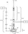
FIG. 3 illustrates an inspection system 300 configured to detect particles or defects on a sample using both normal and oblique illumination beams. In this configuration, laser system 330 provides a laser beam 301. The laser system 330 includes a pulsed laser and a repetition rate multiplier as described herein. The lens 302 focuses the beam 301 through a spatial filter 303. Lens 304 collimates the beam and passes it to polarizing beam splitter 305. Beam splitter 305 passes a first polarization component to the normal illumination channel and a second polarization component to the oblique illumination channel, where the first component is orthogonal to the second component. In the normal illumination channel 306, the first polarization component is focused by optics 307 and reflected by mirror 308 towards the surface of sample 309. Radiation scattered by a sample 309 (e.g., a wafer or photomask) is collected by a parabolic mirror 310 and focused to a sensor 311.
In the oblique illumination channel 312, the second polarization component is reflected by the beam splitter 305 to the mirror 313, which reflects this beam through the half-wave plate 314 and is focused by the optics 315 to the sample 309. Radiation originating from the tilted illumination beam in the tilted channel 312 and scattered by the sample 309 is collected by the parabolic mirror 310 and focused to the sensor 311. The sensor 311 and the illuminated area (from the normal and oblique illumination channels on the sample 309) are preferably at the focal point of the parabolic mirror 310.
FIG. 4 illustrates an exemplary catadioptric imaging system 400 configured as an inspection system with bright-field and dark-field inspection modes. The system 400 incorporates two illumination sources: laser 401 and broadband light illumination module 420. The laser 401 includes a pulsed laser and a repetition rate multiplier as described herein. In a preferred embodiment, laser 401 comprises a DUV or VUV laser, a pulse repetition rate multiplier and/or a flat-top profile generator as described herein.
In the dark field mode, the adaptive optics 402 control the laser illumination beam size and profile on the surface being inspected. The mechanical housing 404 includes an aperture and window 403 and a prism 405 to redirect the laser light along the optical axis at a normal incidence angle to the surface of the sample 408. Prism 405 also directs specular reflections from surface features of sample 408 out of objective 406. Objective 406 collects light scattered by sample 408 and focuses it on sensor 409. The lenses for objective 406 may be provided in the general form of a catadioptric objective 412, a focusing lens group 413 and a tube lens section 414 (which optionally includes zoom power).
In bright field mode, broadband illumination module 420 directs broadband light to beam splitter 410, which beam splitter 410 reflects the light toward focusing lens group 413 and catadioptric objective 412. Catadioptric objective 412 illuminates sample 408 with broadband light. Light reflected or scattered from the sample is collected by objective 406 and focused on sensor 409. The broadband illumination module 420 includes, for example, a laser-excited plasma light source or an arc lamp. Broadband illumination module 420 may also include an autofocus system to provide signals that control the height of sample 408 relative to catadioptric objective 412.
Fig. 5 illustrates an exemplary pulse repetition rate multiplier 120A configured to receive an input laser pulse (input) and generate a pulse train (output) having a repetition rate that is three times the repetition rate of the input laser pulse. Similar to the scheme described in the above-referenced' 075 U.S. patent application, a Polarizing Beam Splitter (PBS) a01 serves as the input and output couplers of the ring cavity. The input laser light was polarized with respect to PBS a01 p. PBS a01 is designed and oriented so as to receive the input laser pulses, pass p-polarized, and reflect s-polarized. Two additional PBSs (a02 and a03) and three fold mirrors (a04, a05, a06) form a dual cavity. The dual cavity also contains two half-wave plates: one placed between a01 and a02 and the other placed between a03 and a 06. When the laser pulse enters the dual cavity through PBS a01, it will be split into two pulses by PBS a 02. Portions of the pulse are reflected from PBS a02 to PBS a03, from PBS a03 to mirror a06, and then from mirror a06 back to PBS a01 (shown as loop a). Another portion of the pulse is transmitted through PBS a02 to mirror a04, reflected from mirror a04 to mirror a05, reflected from mirror a05 through a03 to mirror a06, and then reflected from mirror a06 back to PBS a01 (shown as loop B). The repetition rate multiplier 120A also includes a first wave plate a07 for changing the polarization of the input laser pulse portion passed from PBS a01 to PBS a02 and a second wave plate a08 for changing the polarization of the input laser pulse portion passed from PBS a03 to mirror a 06. The laser pulse energy distribution between loop a and loop B can be controlled by the angle of the principal axis of the half-wave plate a07 relative to the polarization of the input laser pulse. By selecting the angle of the principal axis of the half-wave plate a08, the ratio of pulse energy recycled into the dual cavity to the energy exiting the dual cavity through PBS a01 can be controlled.
In a preferred embodiment, the optical path length of loop a is set to about one-third of the inter-pulse distance of the input laser pulses, and the path length of loop B is set to about twice the path length of loop a. This results in output pulses at about one-third and two-thirds of the time interval between input laser pulses and approximately coincident with the input pulses, thus tripling the repetition rate of the laser. In this embodiment, the angles α and β of the major axes of the waveplates a07 and a08 are preferably set at about α -29 ° and β -16 °, respectively, or at about α -16 ° and β -29 °, respectively, in order to produce about equal energy in each output pulse. If a small difference (e.g., a few percent) in energy per pulse is acceptable in a particular application, then an angle of one or two degrees from such a value is acceptable. A lens (not shown) may be incorporated into the dual chamber and/or one or more of mirrors a04, a05, and a06 may be curved so that the gaussian beam waist and magnitude of each pulse re-images to the same condition as the pulse returns to the same location.
Repetition rates other than three can be achieved using this dual chamber. For example, loop A may be set to have an optical path length approximately equal to a separated quarter of the input pulse, and loop B is set to be approximately twice the length of loop A. This will result in a quadruple repetition rate of the input laser pulses. However, this scheme cannot produce equal output pulse energies and therefore will only be useful when equal output pulse energies are not needed.
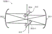
Fig. 6 illustrates another pulse repetition rate multiplier 120B that may triple the repetition rate. Similar to the Herriott (Herriott) cell scheme described in the above-referenced' 593 U.S. patent application, this pulse repetition rate tripler includes an optical cavity formed by a pair of curved mirrors (B01 and B02). The curved mirrors B01 and B02 are preferably spherical mirrors. The pulse repetition rate tripler 120B also includes two beam splitters (B03, B04) and two beam compensators (B05, B06). The radii of curvature of both curved mirrors B01 and B02 should preferably be substantially equal to the distance between them (i.e., the cavities should be confocal).
The laser input pulse (input) reaches beam splitter B03. The portion of the energy of each pulse is reflected from beam splitter B03 to point B07 on curved mirror B01, then to point B08 on curved mirror B02, through beam splitter B04 to point B09 on curved mirror B01, then to point B10 on curved mirror B02, and back to beam splitter B03. The other portion of the energy of each pulse is transmitted through beamsplitter B03, to beamsplitter B04, where it is reflected to point B09 on curved mirror B01, then to point B10 on curved mirror B02, and back to beamsplitter B03. In a preferred embodiment, the optical path length of the shorter loop (B03-B04-B09-B10-B03) is about half the optical path length of the longer loop (B03-B07-B08-B04-B09-B10-B03). When the distance between the two curved mirrors B01 and B02 is about one sixth of the original inter-pulse spatial separation of the input laser beam, the output pulse train will have a triple repetition rate of the input pulses. The beam compensators B05 and B06 have selected optical thicknesses and orientations so as to substantially compensate for the displacement of the laser beam within the cavity caused by the beam splitters B03 and B04, respectively.
Similar to the output of the 2x repetition rate multiplier described in the above-referenced' 593 application and illustrated in fig. 2A and 2B of that application, the output of the pulse repetition rate tripler 120B is comprised of a series of pulse trains, each pulse train comprising a series of pulses that have traversed one or more times one or both of the cavities. The pulse repetition rate tripler 120B has three output pulse trains per input pulse as compared to two output pulses per input pulse for a 2x repetition rate tripler. In the preferred embodiment of the pulse repetition rate tripler, by reflection from beam splitters B03 and B04The rate is set to be approximately equal to And
And (i.e., about 0.28 and about 0.72) so that the total energy in each output pulse train is approximately equal to each other. Note that B03 may have a reflectivity of about 0.28 and B04 may have a reflectivity of about 0.72, or B04 may have a reflectivity of about 0.28 and B03 may have a reflectivity of about 0.72. Both configurations produce substantially equal output pulse energies. Since a few percent of the pulse-to-pulse energy variation is acceptable in many inspection applications, the beam splitter reflectivity can be selected to have values that differ by a few percent from 0.28 and 0.72. As understood by those skilled in the art, the reflectivity of the beam splitter can be controlled by the selection of the beam splitter material, the thickness of any one or more layers coated on the surface, and the material and angle of incidence on the beam splitter.
Fig. 7A illustrates a repetition rate multiplier 120B-1 according to another embodiment, utilizing curved mirrors (B01 and B02) and a beam splitter in a manner similar to that illustrated in fig. 6, but with the difference that two beam compensators (B05 and B06, see fig. 6) are removed. Figure 7A shows that with the positions of beam splitters B03-1 and B04 appropriately adjusted, beam displacement caused by one of the beam splitters can be compensated for by the other beam splitter and vice versa. Preferably, the two beam splitters B04 and B03-1 have substantially equal optical thicknesses. FIG. 7B illustrates a repetition rate multiplier 120B-2 according to another embodiment, in which beam splitter B03-2 is positioned with its coated side turned to another direction relative to beam splitter B03-1 of FIG. 7A. In either embodiment, there may be a closed loop and no beam compensator is needed.
Fig. 8 illustrates another repetition rate multiplier 120D that may quadruple the repetition rate. The repetition rate multiplier 120D includes an optical cavity formed by two curved mirrors B01 and B02 (similar to the curved mirrors described above with respect to fig. 6), two beam splitters D01 and D06, and two fold mirrors D05 and D07. The input laser repetition rate is first doubled in a manner similar to that described in the above-referenced' 593 U.S. patent application by using one beam splitter D01 (preferably having a reflectivity of about 2/3) and one beam compensator or prism D02 (main cavity loop). The output beam D03 is then turned back to the cavity by right angle prism D04 and mirror D05. The beam then follows a path shown as a dashed line to another beam splitter D06 (preferably with a reflectivity of about 1/3), and a secondary cavity loop (dashed line) starts at D06, to spherical mirror B01, spherical mirror B02, then another flat mirror D07, and returns to beam splitter D06. This secondary cavity path loop is about half the length of the first loop, so it doubles the repetition rate a second time and makes the output pulse train four times the initial input pulse repetition rate.
The special feature of this scheme is that this secondary cavity loop, which further multiplies the repetition rate a second time, utilizes the same set of curved mirrors (B01 and B02) as the first cavity loop. In addition, the plane mirrors D05 and D07 may be combined into one optical element with a High Reflectivity (HR) coating on both sides. Such features result in a more compact footprint compared to an arrangement comprising two individual 2x pulse multipliers connected together in series. Note that, while convenient, it is not required to combine mirrors D07 and D05, and beam D03 may be directed along a different path than shown to reach beam splitter D06. Alternative layouts are possible and within the scope of this embodiment.
Fig. 9 illustrates another repetition rate multiplier 120E that doubles the repetition rate as previously discussed. The repetition rate multiplier 120E includes an optical cavity formed by curved mirrors B01 and B02 and a beam splitter B03 in a manner similar to that described above with respect to fig. 6. An isosceles triangular prism E01 is used here in place of the compensator B05 of the previous embodiment.
Fig. 10A and 10B illustrate useful features of an isosceles triangular prism E01: (1) which displaces the beams and can be adjusted by moving the prism laterally, and (2) if multiple beams enter the prism in parallel, the spatial sequence of the output beams will be reversed. Such isosceles triangular prisms may also be implemented as isosceles trapezoids or dove prisms.
Fig. 11A and 11B illustrate two similar flat-top beam generators 102E-1 and 102E-2, respectively, utilizing repetition rate multipliers 120E-1 and 120E-2 to split an input laser pulse (input) received from lasers 119E-1 and 119E-2 into two laterally shifted (separate round-trip optical) output beam paths, thereby generating an output laser pulse (output) having a time-averaged flat-top beam profile with a pulse repetition rate that is double (twice) the pulse repetition rate of the input laser pulse, according to an exemplary embodiment. The repetition rate multipliers 120E-1 and 120E-2 comprise two spherical/cavity (curved) mirrors B01 and B02, a beam splitter B03, and an isosceles triangular prism E01 arranged in a manner similar to the embodiment described above with respect to fig. 9. Fig. 11A shows the nominal optical path of fig. 9 as a dashed line. In the embodiment shown in FIG. 11A, the beam in the cavity is displaced to route E02 due to a small displacement of the input beam (e.g., by displacing laser light 119E-1 in the direction indicated by the thick arrow at the bottom of FIG. 11A). After the laser pulse has completed one pass around the cavity on path E02, prism E01 laterally shifts the laser pulse to path E03 on the opposite side of the nominal course. The pulse on route E03 switches again to route E02 as it returns to the prism E01. Thus, the laser pulses will alternate between routes E02 and E03.
Whenever a laser pulse encounters beam splitter B03, part of the energy of the pulse is reflected and exits the system. The pulse traveling on route E02 produces a pulse on exit route E04, and the pulse on route E03 produces a pulse on exit route E05. With this arrangement, one gaussian beam is spatially split into two gaussian beams. By controlling the separation between E04 and E05, the degree of overlap between the two laser beams can be controlled. In a preferred embodiment, the output beam profile possesses an approximately flat-top time-averaged intensity, as illustrated in fig. 12. By shifting one Gaussa beam waist radius relative to another Gauss (i.e., the beam amplitude is 1/e of its peak value)2The radius at (a), or equivalently the beam power density is 1/e of its peak) to produce an approximately flat-top output beam profile. This flat top profile may be highly desirable in many applications where a homogenized spatial power distribution is required. Note that because the laser pulses on paths E04 and E05 are compared to one other pulseExits the cavity at a time that is separated in duration by a longer time (e.g., separated in time by about half of the time interval between input laser pulses), so there is no interference of one pulse with the other, resulting in a desired relative flat-top profile. Interference between the two shifted gaussians, which can occur without a sufficiently long time delay between pulses, can cause non-flat tops of the profiles.
FIG. 11B illustrates a flat-top beam generator 102E-2 having a repetition rate multiplier 120E-2 configured according to another exemplary embodiment to generate laser pulses (outputs) having a flat-top beam profile. Instead of shifting the input beam by shifting the position of the laser 119E-2, the prism E01 is shifted towards the cavity axis (as indicated by the thick arrow at the bottom of the figure) and thus the pulse is diverted from the nominal route E06 (solid line) to the new route E07 (dashed line). Each pulse will then go back and forth (i.e., shift laterally) between routes E06 and E07 whenever it travels through prism E01 after the cavity round-trip. Similar to the embodiment of fig. 11A, two output beams will be produced when the pulse passes through beam splitter B03 under two different routes, and a time-averaged flat-top beam profile can be formed by appropriately adjusting the beam separation.
The above-described repetition rate multipliers 120E-1 and 120E-2 (which facilitate the flat-top scheme shown in FIGS. 11A and 11B) are based on a scheme (e.g., the arrangement described above with reference to FIG. 9) that doubles the repetition rate. Thus, it is advantageous that one optical cavity not only extends the laser pulse energy distribution in the time domain but also homogenizes the energy distribution in the spatial domain.
Fig. 13 illustrates another flat-top beam generator 102F that utilizes a repetition rate multiplier 120F to receive input laser pulses generated by a laser 119F and generates output laser pulses F03 and F04 having time-averaged flat-top beam profiles using a 3x pulse repetition rate multiplying system similar to that described above and illustrated in fig. 6, in accordance with another embodiment. In this embodiment, beam splitter B04 is shifted down from its nominal position (compared to fig. 6) and an isosceles or duff prism F06 is used in place of beam compensator B06 to shift the beam laterally in the manner described above, thus creating two beam paths. Each time a laser pulse passes through the beam splitter B03 and B04 (perpendicular to the cavity axis) and as it passes through the prism F06, the pulse switches between an outer path F01 (solid line) and an inner path F02 (dashed line). When the laser pulse encounters beam splitter B04, a portion of the energy of the pulse will exit the system. In a preferred embodiment, the beam splitter reflectivity is selected such that the average output power of F03 is approximately equal to the average output power of F04. In a preferred embodiment in which the beam splitter losses are minimal, the beam splitter reflectivity is selected so as to be approximately Wherein R isB03And RB04The reflectivities of beam splitters B03 and B04, respectively. Preferably, the thicknesses of both the beam splitter and the beam compensator are equal, so that it is straightforward to align the optics to achieve two closed loops within the optical cavity.
Alternatively, FIGS. 14A and 14B illustrate exemplary flat-top beam generators 102G-1 and 102G-2, respectively, utilizing repetition rate multipliers 120G-1 and 120G-2, respectively, having a configuration similar to FIG. 13 but without the use of any beam compensators or prisms, repetition rate multipliers 120G-1 and 120G-2 receiving input laser pulses generated by lasers 119G-1 and 119G-2, respectively, and generating output laser pulses (output) having a flat-top beam profile, according to other embodiments. With the beam splitter positions properly arranged (e.g., by moving beam splitter B04-1 to the right (as indicated in fig. 14A), or by moving beam splitter B04-2 to the left (as indicated in fig. 14B)), a flat-top beam profile can be produced in a 3x multiplier based scheme without the use of any compensators or prisms. In addition, the coatings of the beam splitters may face in different directions (fig. 14A) or in the same direction (fig. 14B). The embodiments in fig. 14A and 14B may also be considered derivatives of the arrangements shown in fig. 7A and 7B, where one of the beam splitters is offset in position, which causes the beam to split into two, and thus produce a time-averaged flat-top output profile at the appropriate offset.
Fig. 15A illustrates another exemplary flat-top beam generator 102H that utilizes a 4x repetition rate multiplier 120H having a scheme (referred to herein as "nominal") similar to that shown in fig. 8. This embodiment may produce a wider, flatter output profile compared to a 3x repetition rate multiplier. By utilizing the mechanism illustrated in fig. 11B, the downward displacement prism D02 causes the first stage output beam D03 to split into two (D03 and H01). Further, moving the prism D04 toward the left side displaces the split beams D03 and H01 to one side of the nominal path (dashed line). These two beams multiply to the nominal other side after entering the second cavity formed by beamsplitter D06, mirror B01, mirror B02, and mirror D07. Thus, there will be four beams (H02, H03, H04, H05) exiting the system through beam splitter D06. Note that the dashed line in the drawings is the nominal beam path that exists only when the right angle prism is not displaced, and is used here for reference only. In which case no beam actually passes through this nominal path.
To produce a flat-topped beam ensemble, three parameters need to be arranged in appropriate relation. By appropriate adjustment of the displacement distance of the prism D02, the space (a) between D03 and H01, and thus the space between H02 and H03 and the space between H04 and H05, can be tuned. By adjusting the displacement of the prism D04, the space (b) between H03 and H04 can be tuned. Finally, the beam splitter D01 reflectivity may be selected so that beams D03 and H01 have different powers with desired ratios.
Fig. 15B illustrates an exemplary output beam profile resulting from this arrangement of fig. 15A. In this exemplary embodiment, for an input Gaussian beam radius w (1/e)2Define) from a-0.9 w, b-0.86 w to produce a flat-topped output profile, the reflectivity R of the beam splitter D01D01Is-0.65 and the reflectivity R of the beam splitter D06D06Is-0.33. This example produces a substantially flat-topped time-averaged output profile having a width of about 2.3 w. Other combinations may also function depending on how flat the profile is desired.
In the above-referenced '075 and' 593 applications, which are incorporated herein by reference, alternative embodiments of a laser pulse repetition rate multiplier are described. Such applications illustrate how the repetition rate of a pulsed laser is doubled using a ring cavity of appropriate length by using a beam splitter to direct about 2/3 of the energy of each input pulse into the cavity while directing 1/3 of the energy of each pulse to the output. Where the cavity optical path length corresponds to about half of the time interval between input laser pulses, the output pulse train forms an envelope of substantially similar energy that repeats at a repetition rate that is twice the repetition rate of the original laser pulses. The' 593 application also describes how to adjust the transmissivity and reflectivity of the beam splitter so as to maintain substantially equal output pulse energies to compensate for losses in the beam splitter and ring cavity. Any of the principles described in the '075 and' 593 applications may be suitably applied to the various embodiments of the pulse repetition rate multiplier described herein.
A detailed description of one or more embodiments of the invention is provided above along with accompanying figures that illustrate the principles of the invention. The invention is described in connection with such embodiments, but the invention is not limited to any embodiment.
For example, in one embodiment, the optical component may be coated with a suitable coating for the laser wavelength. Each surface of any transmissive element (e.g., a waveplate) may also have an anti-reflective coating that minimizes the amount of laser energy reflected at each surface. The mirrors may be coated with a coating designed to maximize reflection and minimize scattering at the laser wavelength.
In another example, in one embodiment, the herriott cell cavity may have a different shape or number of mirrors than the example given above.
While the embodiments illustrated above are drawn in one plane, alternative embodiments may place one of the cavity loops (e.g., the secondary cavity loop in fig. 8 or 15A) in a plane that is approximately perpendicular to or rotated relative to the plane of the other cavity loop (e.g., the primary cavity loop), while still using the same set of mirrors. For example, fig. 16A and 16B are front and side views showing a 2x pulse repetition rate multiplier arrangement in which the input and output pulses are directed in a plane perpendicular to the plane of the cavity loop formed by beam splitter D01, beam compensator or prism D02, and curved mirrors B01 and B02. Fig. 16C and 16D are front and top views showing a 4x arrangement, where one or more mirrors or prisms may be used outside the cavity to direct or deflect light from prism D04 to mirror D05 located in the plane of the secondary loop. Note in fig. 16D that the input and output beams, the plane of the 2x cavity loop, the beam splitter D01 and the beam compensator or prism D02 are shown as dashed lines as seen from above for reference. The optical components of one cavity loop are positioned so that they do not intersect the other cavity loops. An advantage of placing the different cavity loops in different planes is that each of the cavity loops can reflect from a curved mirror (e.g., mirrors B01 and B02) at a substantially similar distance from the center of the mirror (as shown in fig. 16C, where the dashed lines show the input and output light paths as viewed from the front and the plane of the 2x loop), allowing the cavity loops to be in focus at the same time and thus minimizing aberrations of the laser beam as it traverses the cavity loops multiple times. By orienting and shifting the prisms D02 and D04 in the appropriate directions in a manner similar to that illustrated in fig. 15A, the 4x laser pulse repetition rate multipliers shown in fig. 16C and 16D can produce an output having a time-averaged substantially flat-top profile similar to that shown in fig. 15A.
Fig. 17 illustrates an exemplary laser pulse repetition rate multiplier 120I configured to generate a pulse train having a repetition rate that is twice the repetition rate of input laser pulses (which are generated by a laser (not shown) in the manner described above). Similar to the concepts described in the above-referenced' 593 U.S. patent application, the beam splitter (I01) is placed in a ring cavity having an optical path length approximately equal to half of the time interval between two consecutive input laser pulses. The ring cavity includes two right-angle reflection pair optics, such as prisms (I02 and I03) that reflect the laser pulses by Total Internal Reflection (TIR). The right angle reflection pair optics I02 and I03 have several advantages over mirrors when used in the ring cavity of the laser repetition rate multiplier 120I. One disadvantage of mirrors is that they require a high reflectivity coating in order to minimize losses as the laser pulses circulate in the ring cavity. High reflectivity coatings can be damaged by the peak power of the laser pulse, especially for deep UV lasers with powers of several hundred mW or higher. The use of TIR instead of high reflectivity coatings eliminates the risk of the coating being damaged when operated with high laser power for long periods of time. A second advantage of using prisms instead of mirrors is that the four mirrors required to form the two mirror-based orthogonal reflection pair elements are replaced by two prisms, thereby reducing the number of optical components. A third advantage of using prisms is that the right angle between the two TIR surfaces of one prism is fixed and can be manufactured with high precision. The tight angular tolerance of the prisms and the reduced number of optical components simplify the alignment of the ring cavity of FIG. 17.
As illustrated in the' 593 application, in the laser pulse repetition rate doubler, if it is desired that each output pulse have substantially equal total energy, the beam splitter I01 should be designed to reflect substantially 2/3 (second) portion of the energy of each input laser pulse into the ring cavity and transmit substantially 1/3 (first) portion of each input laser pulse, such that 1/3 portion exits the repetition rate doubler 120I at a first time, and such that 2/3 portion exits the repetition rate doubler 120I at a second time after being reflected between reflective elements I02 and I03. This can be achieved, for example, by using a suitable coating on the beam splitter I01. Note that if substantially equal output pulse energies are not required, beam splitter I01 may be designed to reflect some portion of each laser pulse other than 2/3. For example, when used in an inspection system, it may be desirable for each output pulse to have substantially equal peak power to allow operation close to the damage threshold of the object being inspected. Substantially equal peak powers of the output pulses may be achieved using a beam splitter that reflects about 62% of each laser pulse into the ring cavity.
As illustrated in the' 593 application, the optical path length of the ring cavity may be set slightly longer or shorter than a distance equal to half of the time interval between input laser pulses in order to widen the output pulses and reduce the peak power of each output pulse and thus reduce the likelihood of damage to downstream optics or to articles inspected or measured by systems incorporating laser repetition rate multipliers.
For example, if the input laser pulses have a repetition rate of 120MHz, a ring cavity optical path length of about 1.249m will result in a repetition rate that is doubled, with the output pulses having about equal spacing in time. To achieve this ring cavity optical path length, the physical distance between the prisms would need to be about 0.625 m. As understood by those skilled in the art, since the laser pulse travels a short distance inside each prism I01 and I02 and the refractive index of the prism material is greater than 1, the optical path length within the prism is slightly longer than the physical distance the laser pulse travels inside the prism. A suitably small adjustment to the physical distance between the prisms can be made to compensate for this in order to achieve the required ring cavity optical path length. If it is desired that the output pulses are wider than the input pulses in order to reduce the peak power of each pulse, the ring cavity optical path length may be set slightly longer or slightly shorter than 1.249m (e.g., a ring cavity optical path length of 1.25 m) so that a pulse that has traveled twice around the ring cavity arrives about 6ps (picoseconds) later than the next input pulse.
In a preferred embodiment, the ring cavity of the repetition rate multiplier 120I preferably includes an optical plate I04 to substantially compensate for the shift in laser beam position caused by the laser pulses passing through the beam splitter I01. The optical plate I04 should preferably have an optical thickness substantially equal to the optical thickness of the beam splitter I01. Optical plate I04 should preferably be coated with an anti-reflective coating in order to minimize reflection of the laser light from its surface. If the optical plate I04 is placed in the same branch of the ring cavity (as shown), then preferably the optical plate I04 should be oriented relative to the input laser beam (pulse) at an angle that is substantially a mirror image of the beam splitter I01 angle relative to the laser beam angle in order to substantially compensate for the beam shift caused by beam splitter I01. If optical plate I04 is placed in the other branch of the ring cavity (not shown), it should preferably be oriented substantially parallel to beam splitter I01.
Fig. 18 illustrates another laser pulse repetition rate multiplier 120J that is similar to the laser pulse repetition rate multiplier of fig. 17 but with one of its right angle prisms (J02) rotated 90 ° relative to the other right angle prism (J03). In comparison to the configuration of fig. 17, the laser pulse repetition rate multiplier 120J of fig. 18 can achieve the same ring cavity optical path length with substantially half of the physical separation between the two prisms, thus resulting in a more compact laser pulse repetition rate multiplier. The beam splitter J01 and optical plate J04 perform the same functions as the beam splitter I01 and optical plate I04 of fig. 17. Note that optical plate J04 can be placed in any of the four branches of the annular cavity according to the appropriate choice of orientation of the plate.
19A, 19B, and 19C illustrate an exemplary embodiment in which the ring cavity optical path length is substantially equal to two times the physical separation of the prisms (FIG. 19A), four times (FIG. 19B), six times (FIG. 19C), or other even integer multiples by rotating one of the right angle prisms shown (or equivalently, the right angle mirror pair) to the appropriate angle relative to the other prism/mirror pairs. The number of loops around the ring cavity, each pulse must pass before returning to its original transmit position (e.g., a beam splitter, which is not shown in fig. 19A-19C), is m-180 °/θ, where θ is the relative angular degree between the two prisms (or mirror pairs). Referring to fig. 19A, when θ is 0 or equivalently 180 °, m is 1 and the beam remains in one plane and only completes one loop around the ring cavity before returning to its original position. Referring to fig. 19B, when θ is 90 °, m is 2 and each laser pulse completes two loops around the ring cavity so as to return to its original position. Referring to fig. 19C, when θ is 60 °, m is 3 and the beam returns to the original transmit position after three loops around the ring cavity. Polarization is preserved throughout the time the beam returns to its original position.
A key benefit of this design is to maintain substantially the same cavity footprint when the ring cavity optical path length is changed by simply rotating one of the prisms.
FIG. 20 illustrates another repetition rate multiplier 120K in accordance with an exemplary embodiment, in which two ring cavities of different optical path lengths are connected in series to quadruple the repetition rate of the pulsed laser light. The two ring cavities have substantially similar outer dimensions, although one ring cavity has twice the optical path length of the other ring cavity. The first ring cavity includes a beam splitter K01, prisms K03 and K02, and an optical plate K04. The first cavity doubles the repetition rate by using two loops around the ring cavity to achieve the desired optical path length. The second annular chamber includes a beam splitter K11, prisms K12 and K13, and an optical plate K14. The second annular cavity doubles the repetition rate a second time using a single loop around the annular cavity. Since the spatial distance between successive pulses is halved after doubling the repetition rate, the second annular cavity should preferably have substantially half the optical path length of the first annular cavity.
Two ring cavities can be made from the same optical assembly. Since both cavities may have substantially similar external dimensions, most of the mounting hardware and mechanical design may be the same. Space may be used more efficiently than designs in which one ring cavity has about twice the physical length of the other ring cavity.
Fig. 21 illustrates the ring cavity portion of the repetition rate multiplier 120L according to an exemplary lens configuration inserted into the ring cavity formed by prisms L02 and L03 such that the laser beam is substantially refocused (imaged) back to its original beam condition (waist position and size) when returning to its original position after one loop around the ring cavity. Lenses L05 and L06 should preferably have equal focal lengths selected so as to form a beam waist at the center of the cavity, and the lenses are preferably positioned as far away from the waist as possible to avoid high laser power densities near the beam waist. Other components of the laser pulse repetition rate multiplier, such as the beam splitter and optical plate, are omitted from this figure for clarity.
Fig. 22 illustrates another annular cavity portion of the repetition rate multiplier 120M in which the same lens configuration inserted in the 2-loop cavity (i.e., prisms L02 and L03 and lenses L05 and L06, see fig. 21) will image the laser beam back to its original beam condition (waist position and size) when returned to its original position. Similarly, this lens configuration will correctly re-image the laser beam for any number of loops around the ring cavity.
Fig. 23 illustrates another annular cavity portion of the repetition rate multiplier 120N utilizing another exemplary lens configuration using two prisms N02 and N03 and two lenses N05 and N06 arranged so that the laser beam is imaged back to its original beam condition (waist position and size) when returned to its original position. In this embodiment, lenses N05 and N06 should preferably have a focal length approximately equal to the cavity length and be positioned close to the prism so that the beam waist is formed near the center of the cavity rather than overly close to either the prism or the lens surface.
Fig. 24 illustrates another annular cavity portion of repetition rate multiplier 120O utilizing another exemplary lens configuration similar to fig. 23, but with each spherical lens replaced by a pair of cylindrical lenses (i.e., spherical lens N05 replaced by cylindrical lenses O051 and O052, and spherical lens N06 replaced by cylindrical lenses O061 and O062). Each cylindrical lens is preferably oriented close to the brewster angle with respect to the direction of propagation and polarization of the laser beam. An advantage of orienting the lenses at or near the brewster angle of p-polarization is that the reflectivity of each lens surface will be very low and no coating is used, thus saving the cost of the coating and avoiding any coating damage caused by the laser. The curvature of one cylindrical lens of each pair is oriented orthogonal to the curvature of the other cylindrical lens of the same pair (i.e., the curvatures are sagittal and tangential) so that they collectively re-image the beam in a manner substantially similar to one of the spherical lenses shown in fig. 23.
Fig. 25A illustrates another exemplary embodiment of a laser pulse repetition rate multiplier 120P with a modified pair of right angle prisms (P01 and P02). Prism P01 serves the same function as prism I02 in fig. 17, except that prism P01 is cut and positioned so that for P-polarization of the laser beam, the angle of incidence is close to brewster's angle. Thus, an AR coating at the prism is not needed and potential coating damage at high laser power is avoided. Prism P02 has the same shape as prism P01 and is also oriented close to brewster's angle with respect to the P-polarization of the laser beam. The prism P02 has an additional coating around only the point P (not the entire surface) which acts as a beam splitter coupling light into and out of the cavity. This eliminates the need for a separate beam splitter assembly, thus reducing the number of optical components and simplifying alignment of the ring cavity. As explained above, in one preferred embodiment, the coating is designed to reflect about 2/3 the energy of each incident laser pulse in order to produce substantially equal energy in each output laser pulse.
Fig. 25B illustrates another exemplary embodiment of a laser pulse repetition rate multiplier 120Q similar to that of fig. 25A, utilizing the same prism P01, but with the prism P02 of fig. 25A replaced by a prism Q02 having a modified shape. This shape enables the input and output beams to be parallel to each other, which is generally desirable as it makes it simpler to integrate the laser pulse repetition rate multiplier into the system. Prism Q02 maintains a right angle between the TIR faces of the prism and uses an angle of incidence close to the brewster angle for the laser beams in the ring cavity. As described above for prism P02, a coating is required around position P in order for the prism to perform the beam splitter function.
Fig. 26A and 26B illustrate a repetition rate multiplier 120R according to an exemplary embodiment, in which the effective beam path length can be doubled (or tripled, etc.) for a given physical annular cavity length by rotating one of two right angle prisms R01 and R02, whether brewster angle cut or not. In such a diagram, the prism R02 with a brewster angle cut surface must be rotated with respect to an axis perpendicular to this brewster incident surface so that the beam polarization state and incident angle (i.e., brewster condition) remain the same after rotation.
Fig. 27A and 27B are top and side views, respectively, illustrating a repetition rate multiplier 120S according to another multiplier design having three prisms S01, S02, and S03 (each having a different shape) such that no coating is required at any surface. The prism S01 performs the dual function of a reflector in the ring cavity and a beam splitter that couples beams into and out of the cavity at a desired reflectivity (e.g., a reflectivity of about R-1/3). Note that in the side view shown in fig. 28B, the prism S02 is hidden behind the prism S01. Various angles between the surfaces of the various prisms are indicated in the drawings.
The geometry of prism S01 is shown in fig. 28, 28A, 28B, and 28C. Which utilizes fresnel reflectivity properties as shown in fig. 29A and 29B. For S-polarized light illuminating the surface of fused silica (or any material with a similar refractive index), the reflectance naturally becomes about 33.3% at an incident angle of about 73 °. The input laser beam b1 and the output laser beam b2 are polarized with respect to the surface S1S. However, when the refracted beam passes through surface S2 or S3, it is P polarized. If the angle of incidence on such surfaces (S2 and S3) is close to the brewster angle, the laser beam can pass through with minimal power loss without using any coating, and thus avoiding any possibility of laser damage to the coating.
The prism S02 of the repetition rate multiplier 120S (see fig. 27A) is illustrated in fig. 30, 30A, and 30B. This prism takes advantage of reflections at brewster' S angle at surfaces S4 and S5 while using total internal reflection at surface S6.
The prism S03 of the repetition rate multiplier 120S (see fig. 27A) is illustrated in fig. 31, 31A, 31B, and 31C. It acts as a right angle prism with two surfaces cut at the brewster angle. Such brewster angle cuts are oriented for beam polarization perpendicular to the ring cavity plane, which is different from the prism design P01 in fig. 25A, which is oriented for polarization parallel to the ring cavity plane P01.
FIG. 32A illustrates a repetition rate multiplier 120T according to another exemplary laser pulse repetition rate multiplier configuration with polarization parallel to the ring cavity plane. This configuration forms a rectangular layout and 90 ° beam coupling (in/out), which can be more conveniently incorporated into the instrument. This configuration includes three elements. The beam splitter T01 has a coating on one surface with a selected reflectivity (e.g., a reflectivity of R1/3) at an angle of incidence of 45 ° and an anti-reflection (AR) coating on the other surface. As indicated in fig. 32B, in one preferred embodiment, prism T02 is a Pellin brooka (Pellin Broca) prism that acts as a mirror to deflect the beam by a total of 90 °, with the input and output surfaces at brewster angles with respect to the beam in the ring cavity. The prism T02 uses total internal reflection inside the prism. In this way, there is little energy loss for p-polarized beams without using any coating. In an alternative embodiment, a mirror with a high reflectivity coating is used in place of prism T02. Element T03 is symbolically depicted as a right angle prism. In a preferred embodiment, prism T03 uses a geometry with brewster cut surfaces for polarized light with polarization parallel to the plane of the ring cavity (e.g., design P01 shown in fig. 25A).
In a manner similar to that described above, the right angle prism T03 may be rotated 90 ° about the normal direction of the entrance surface to double the beam path length within the cavity.
FIG. 33 illustrates a repetition rate multiplier 120U according to an exemplary embodiment, where two ring cavities similar to that of the embodiment of FIG. 32A are connected in series to multiply the repetition rate by four times. The first ring cavity U01 rotates one prism by 90 ° so that the optical path length of this cavity is about twice that of the second cavity U02, although both cavities have similar physical dimensions. Together, these two ring cavities form a multiplier that quadruples the repetition rate.
In the above-referenced '075 and' 593 applications, which are incorporated herein by reference, alternative embodiments of a laser pulse repetition rate multiplier are described. Such applications illustrate how the repetition rate of a pulsed laser is doubled using a ring cavity of appropriate length by using a beam splitter to direct about 2/3 of the energy of each input pulse into the cavity while directing 1/3 of the energy of each pulse to the output. Where the cavity optical path length corresponds to about half of the time interval between input laser pulses, the output pulse train forms an envelope of substantially similar energy that repeats at a repetition rate that is twice the repetition rate of the original laser pulses. The' 593 application also describes how to adjust the transmissivity and reflectivity of the beam splitter so as to maintain substantially equal output pulse energies to compensate for losses in the beam splitter and ring cavity. Any of the principles described in the '075 and' 593 applications may be suitably applied to the various embodiments of the pulse repetition rate multiplier described herein.
To achieve even higher repetition rates, multiple cells of any of the above laser pulse repetition rate multipliers may be connected in series, with each cell having a different cavity length. The output repetition rate may be made equal to 2x, 4x, … …, or 2 of the input repetition ratenx, where n is the number of laser pulse repetition rate multiplier cavities, and the optical path length of each cavity is 1/2, 1/4, … … 1/2 of the distance between the original pulsesn。
The above exemplary embodiments illustrate how optical cavities of different lengths are formed by various combinations of flat mirrors, curved mirrors, prisms, and lenses for the purpose of multiplying the repetition rate of pulsed laser light. The repetition rate multiplier or the repetition rate multiplier that produces an output having a time-averaged substantially flat-top profile may be constructed from other combinations without departing from the scope of the present invention. For example, a flat mirror may be replaced by a prism (or, in many cases, vice versa), or a curved mirror may be replaced by a combination of a flat mirror and one or more lenses (or vice versa). The choice of which components to use is determined by a number of practical considerations, including the laser wavelength, the laser power density at the location of the optical component, the availability of suitable optical coatings for the component, physical space and weight. As explained above, prisms and components having brewster angle surfaces are generally preferred where the power density is high enough to potentially damage the optical coating.
The scope of the invention is limited only by the claims and the invention encompasses numerous alternatives, modifications and equivalents. In the previous description, numerous specific details were set forth in order to provide a thorough understanding of the present invention. Such details are provided for the purpose of example and the invention may be practiced according to the claims without some or all of these specific details. For the purpose of clarity, technical materials and derivatives that are known in the technical fields related to the invention have not been described in detail so that the invention is not unnecessarily obscured.
Claims (10)
1. A laser pulse repetition rate multiplier for receiving input laser pulses and for generating output pulses having an output pulse repetition rate that is more than twice the repetition rate of the input laser pulses, the laser pulse repetition rate multiplier comprising:
a Herriott cell comprising first and second curved mirrors forming an optical cavity, first and second beam splitters, and at least two folding mirrors, and a right angle prism positioned outside the optical cavity, the Herriott cell configured such that a portion of each of the input laser pulses travels along a main cavity loop inside the optical cavity, then passes to the right angle prism, then travels along a secondary cavity loop inside the optical cavity before exiting the optical cavity as one of the output pulses generated,
wherein the two curved mirrors have radii of curvature approximately equal to an odd integer multiple of one-fourth of the spatial separation between the input laser pulses, and
wherein the two curved mirrors have a common radius of curvature and are separated by a distance substantially equal to the radius of curvature.
2. The laser pulse repetition rate multiplier of claim 1, wherein the Herriott cell is configured such that the output pulse repetition rate is four times the repetition rate of an original input pulse.
3. The laser pulse repetition rate multiplier of claim 1,
wherein the Herriott cell is configured such that at least a portion of each of the input laser pulses is directed by the first beam splitter so as to be reflected by first portions of the first and second curved mirrors when it is on the primary cavity loop and is directed by the second beam splitter so as to be reflected by second portions of the first and second curved mirrors when it is on the secondary cavity loop,
wherein the Herriott cell further comprises a prism disposed in the main cavity loop, and
wherein one of the prism, the at least two fold mirrors, and the right angle prism is configured to steer laser pulses from the primary cavity loop into the secondary cavity loop.
4. The laser pulse repetition rate multiplier of claim 3, wherein the Herriott cell is configured such that the primary cavity loop lies in a different plane than the secondary cavity loop.
5. The laser pulse repetition rate multiplier of claim 4, wherein the first beam splitter receives the input laser pulses and reflects about two-thirds of the energy of each of the input laser pulses into the main cavity loop.
6. The laser pulse repetition rate multiplier of claim 1, wherein the second beam splitter has a reflectivity of about one-third.
7. The laser pulse repetition rate multiplier of claim 1, wherein the Herriott cell is configured such that:
each said input laser pulse is directed onto said first beam splitter;
the first beam splitter is configured to direct at least a first portion of the each input laser pulse so as to be reflected by the first and second curved mirrors in a first plane when the first portion is on the main cavity loop, and then directed toward the right angle prism;
the right angle prism is configured to redirect the first portion to the second beam splitter; and is
The second beam splitter is configured to direct at least a second portion of each of the first portions such that when the second portion is on the secondary cavity loop it is reflected by the first and second curved mirrors in a second plane, the second plane being different from the first plane.
8. The laser pulse repetition rate multiplier of claim 1,
wherein the Herriott cell further comprises one of a beam compensator and a prism disposed in a first plane with the first beam splitter, and
wherein the second beam splitter and the at least two folding mirrors are disposed within a second plane.
9. A repetition rate multiplier for receiving input laser pulses and for generating output pulses having an output pulse repetition rate that is at least twice the repetition rate of the input laser pulses, the laser pulse repetition rate multiplier comprising:
at least one beam splitter and two light reflecting elements forming a ring cavity,
wherein the at least one beam splitter is configured to direct a first energy portion of each input laser pulse such that the first energy portion exits the repetition rate multiplier at a first time, and is configured to direct a second energy portion of the input laser pulse into the ring cavity such that the second energy portion reflects between the two reflective elements and exits the repetition rate multiplier at a second time,
wherein the two light reflecting elements comprise a first curved mirror and a second curved mirror,
wherein the at least one beam splitter comprises:
a first beam splitter configured to direct the first and second energy portions into the ring cavity, and
a second beam splitter configured to direct the second energy portion of each of the input laser pulses out of the repetition rate multiplier after the second energy portion traverses between a first reflective element and a second reflective element at least once;
the repetition rate multiplier further comprises:
a prism disposed in the ring cavity,
at least two folding mirrors disposed in the ring cavity; and
a right angle prism positioned outside the ring cavity,
wherein the first beam splitter and the prism are configured such that a first energy portion of each of the input laser pulses is transmitted along a main cavity loop within the annular cavity,
wherein the second beam splitter and the at least two folding mirrors are configured such that a second energy portion of each of the input laser pulses is transmitted along a secondary cavity loop within the toroidal cavity, and
wherein the right angle prism is configured to direct the first portion of energy away from the primary cavity loop to the secondary cavity loop.
10. The repetition rate multiplier of claim 9,
wherein the first beam splitter is configured to direct the first energy portion of the each input laser pulse so as to be reflected by the first and second curved mirrors in a first plane when the first energy portion is on the main cavity loop,
wherein the right angle prism is configured to direct the first portion of energy out of the main cavity loop to the second beam splitter, and
wherein the second beam splitter is configured to direct the second portion of energy such that when the second portion of energy is on the secondary cavity loop it is reflected by the first and second curved mirrors in a second plane, the second plane being different from the first plane.
Applications Claiming Priority (7)
| Application Number | Priority Date | Filing Date | Title |
|---|---|---|---|
| US201462015016P | 2014-06-20 | 2014-06-20 | |
| US62/015,016 | 2014-06-20 | ||
| US201462038471P | 2014-08-18 | 2014-08-18 | |
| US62/038,471 | 2014-08-18 | ||
| US14/596,738 US9525265B2 (en) | 2014-06-20 | 2015-01-14 | Laser repetition rate multiplier and flat-top beam profile generators using mirrors and/or prisms |
| US14/596,738 | 2015-01-14 | ||
| CN201580027977.5A CN106415952B (en) | 2014-06-20 | 2015-06-18 | The laser repetition rate multiplier and flat-topped beam profile generator of using face mirror and/or prism |
Related Parent Applications (1)
| Application Number | Title | Priority Date | Filing Date |
|---|---|---|---|
| CN201580027977.5A Division CN106415952B (en) | 2014-06-20 | 2015-06-18 | The laser repetition rate multiplier and flat-topped beam profile generator of using face mirror and/or prism |
Publications (2)
| Publication Number | Publication Date |
|---|---|
| CN110797743A CN110797743A (en) | 2020-02-14 |
| CN110797743B true CN110797743B (en) | 2021-07-06 |
Family
ID=54870513
Family Applications (2)
| Application Number | Title | Priority Date | Filing Date |
|---|---|---|---|
| CN201911029361.8A Active CN110797743B (en) | 2014-06-20 | 2015-06-18 | Laser repetition rate multiplier and flat-top beam profile generator using mirrors and/or prisms |
| CN201580027977.5A Active CN106415952B (en) | 2014-06-20 | 2015-06-18 | The laser repetition rate multiplier and flat-topped beam profile generator of using face mirror and/or prism |
Family Applications After (1)
| Application Number | Title | Priority Date | Filing Date |
|---|---|---|---|
| CN201580027977.5A Active CN106415952B (en) | 2014-06-20 | 2015-06-18 | The laser repetition rate multiplier and flat-topped beam profile generator of using face mirror and/or prism |
Country Status (7)
| Country | Link |
|---|---|
| US (2) | US9525265B2 (en) |
| EP (1) | EP3117495B1 (en) |
| JP (2) | JP6663865B2 (en) |
| KR (1) | KR102249336B1 (en) |
| CN (2) | CN110797743B (en) |
| IL (1) | IL248648B (en) |
| WO (1) | WO2015195877A1 (en) |
Families Citing this family (21)
| Publication number | Priority date | Publication date | Assignee | Title |
|---|---|---|---|---|
| US9151940B2 (en) | 2012-12-05 | 2015-10-06 | Kla-Tencor Corporation | Semiconductor inspection and metrology system using laser pulse multiplier |
| US9804101B2 (en) | 2014-03-20 | 2017-10-31 | Kla-Tencor Corporation | System and method for reducing the bandwidth of a laser and an inspection system and method using a laser |
| US9525265B2 (en) * | 2014-06-20 | 2016-12-20 | Kla-Tencor Corporation | Laser repetition rate multiplier and flat-top beam profile generators using mirrors and/or prisms |
| US9748729B2 (en) | 2014-10-03 | 2017-08-29 | Kla-Tencor Corporation | 183NM laser and inspection system |
| CN104319615B (en) * | 2014-11-02 | 2017-12-26 | 中国科学院光电技术研究所 | A kind of quasi-molecule laser pulse broadening device based on double beam splitting elements |
| CN105932531B (en) * | 2016-05-31 | 2018-08-21 | 中国科学院高能物理研究所 | High repetition frequency laser pulse generates and delay time calibration method |
| US10175555B2 (en) | 2017-01-03 | 2019-01-08 | KLA—Tencor Corporation | 183 nm CW laser and inspection system |
| CN107966424B (en) * | 2017-11-02 | 2020-06-30 | 浙江大学 | Side imaging method and device based on anti-telescope system and free-form surface reflection |
| WO2019103299A1 (en) * | 2017-11-23 | 2019-05-31 | 주식회사 프로텍 | Laser apparatus for printed electronics system and operating method thereof |
| US10864042B2 (en) * | 2018-02-20 | 2020-12-15 | Koninklijke Philips N.V. | Optical assembly for laser generator |
| CN109406454B (en) * | 2018-09-11 | 2021-01-15 | 江苏大学 | Improved Z scanning device |
| KR20200120827A (en) | 2019-04-12 | 2020-10-22 | 삼성디스플레이 주식회사 | Laser apparatus and manufacturing method of display appratus using the same |
| JP7320975B2 (en) * | 2019-04-16 | 2023-08-04 | Jswアクティナシステム株式会社 | Laser irradiation device, laser irradiation method, and semiconductor device manufacturing method |
| US10921261B2 (en) | 2019-05-09 | 2021-02-16 | Kla Corporation | Strontium tetraborate as optical coating material |
| GB2593456B (en) * | 2020-03-18 | 2024-02-28 | Thermo Fisher Scient Ecublens Sarl | Double-pulse laser system |
| WO2022203618A1 (en) * | 2021-03-24 | 2022-09-29 | Lumos Lazer Anoni̇m Şi̇rketi̇ | Variable repetition rate multiplier based on polarization rotation |
| CN113484266B (en) * | 2021-05-28 | 2023-01-17 | 汉威科技集团股份有限公司 | Optical path multiplying device and optical path multiplying gas absorption cell |
| CN117795285A (en) * | 2021-06-03 | 2024-03-29 | 诺威有限公司 | Time domain optical metrology and inspection of semiconductor devices |
| WO2023072880A1 (en) * | 2021-10-29 | 2023-05-04 | Asml Netherlands B.V. | Inspection apparatus, polarization-maintaining rotatable beam displacer, and method |
| CN115185093A (en) * | 2022-07-25 | 2022-10-14 | 中国科学院光电技术研究所 | Flat-top laser beam shaping method |
| US20240118556A1 (en) * | 2022-10-06 | 2024-04-11 | Kla Corporation | Systems and methods for generating a flat-top illumination beam based on interlacing, incoherently overlapping spots |
Citations (3)
| Publication number | Priority date | Publication date | Assignee | Title |
|---|---|---|---|---|
| CN1310871A (en) * | 1998-08-20 | 2001-08-29 | 奥宝科技有限公司 | Laser repetition rate multiplier |
| WO2007141185A2 (en) * | 2006-06-09 | 2007-12-13 | Carl Zeiss Laser Optics Gmbh | Homogenizer with reduced interference |
| CN101782723A (en) * | 2008-12-31 | 2010-07-21 | Asml控股股份有限公司 | Pulse modifier with adjustable etendue |
Family Cites Families (90)
| Publication number | Priority date | Publication date | Assignee | Title |
|---|---|---|---|---|
| US4718766A (en) | 1985-02-05 | 1988-01-12 | Greenstein Howard B | Stabilized ring laser bias system |
| US4710030A (en) | 1985-05-17 | 1987-12-01 | Bw Brown University Research Foundation | Optical generator and detector of stress pulses |
| US4999014A (en) | 1989-05-04 | 1991-03-12 | Therma-Wave, Inc. | Method and apparatus for measuring thickness of thin films |
| US5119382A (en) | 1990-12-24 | 1992-06-02 | Mcdonnell Douglas Corporation | Tetravalent chromium doped passive Q-switch |
| US5172382A (en) | 1991-02-05 | 1992-12-15 | Cornell Research Foundation, Inc. | Ultrahigh frequency optical self-modulator |
| US5189481A (en) | 1991-07-26 | 1993-02-23 | Tencor Instruments | Particle detector for rough surfaces |
| US5563702A (en) | 1991-08-22 | 1996-10-08 | Kla Instruments Corporation | Automated photomask inspection apparatus and method |
| US5309456A (en) | 1992-10-30 | 1994-05-03 | The United States Of America As Represented By The United States Department Of Energy | Pulse stretcher |
| US5276548A (en) | 1992-12-01 | 1994-01-04 | Eli Margalith | Ring cavity optical parametric apparatus |
| US6271916B1 (en) | 1994-03-24 | 2001-08-07 | Kla-Tencor Corporation | Process and assembly for non-destructive surface inspections |
| KR100483981B1 (en) | 1996-02-22 | 2005-11-11 | 가부시키가이샤 니콘 | Pulse width-extended optical systems and exposure units with these optical systems |
| US5999310A (en) | 1996-07-22 | 1999-12-07 | Shafer; David Ross | Ultra-broadband UV microscope imaging system with wide range zoom capability |
| US6608676B1 (en) | 1997-08-01 | 2003-08-19 | Kla-Tencor Corporation | System for detecting anomalies and/or features of a surface |
| US6201601B1 (en) | 1997-09-19 | 2001-03-13 | Kla-Tencor Corporation | Sample inspection system |
| US6067311A (en) | 1998-09-04 | 2000-05-23 | Cymer, Inc. | Excimer laser with pulse multiplier |
| KR20000034461A (en) | 1998-11-30 | 2000-06-26 | 전주범 | Pulse generator |
| US6191887B1 (en) | 1999-01-20 | 2001-02-20 | Tropel Corporation | Laser illumination with speckle reduction |
| US6184984B1 (en) | 1999-02-09 | 2001-02-06 | Kla-Tencor Corporation | System for measuring polarimetric spectrum and other properties of a sample |
| US6233052B1 (en) | 1999-03-19 | 2001-05-15 | The Board Of Trustees Of The Leland Stanford Junior University | Analog detection for cavity lifetime spectroscopy |
| US6535531B1 (en) | 2001-11-29 | 2003-03-18 | Cymer, Inc. | Gas discharge laser with pulse multiplier |
| WO2001025849A2 (en) | 1999-09-23 | 2001-04-12 | Purdue Research Foundation | Direct space-to-time pulse shaper and optical pulse train generator |
| US6879390B1 (en) | 2000-08-10 | 2005-04-12 | Kla-Tencor Technologies Corporation | Multiple beam inspection apparatus and method |
| US7136159B2 (en) | 2000-09-12 | 2006-11-14 | Kla-Tencor Technologies Corporation | Excimer laser inspection system |
| US20020105995A1 (en) * | 2000-11-16 | 2002-08-08 | Lambda Physik Ag | Molecular fluorine laser with single spectral line and polarized output |
| US6693930B1 (en) | 2000-12-12 | 2004-02-17 | Kla-Tencor Technologies Corporation | Peak power and speckle contrast reduction for a single laser pulse |
| US7453486B2 (en) | 2000-12-13 | 2008-11-18 | Orbotech Ltd | Pulse light pattern writer |
| AU2002219478A1 (en) | 2001-01-04 | 2002-07-16 | Laser Imaging Systems Gmbh And Co. Kg | Direct pattern writer |
| US7151632B2 (en) | 2001-01-12 | 2006-12-19 | University Of Rochester | Apparatus for production of an inhomogeneously polarized optical beam for use in illumination and a method thereof |
| US6704339B2 (en) | 2001-01-29 | 2004-03-09 | Cymer, Inc. | Lithography laser with beam delivery and beam pointing control |
| US7415056B2 (en) | 2006-03-31 | 2008-08-19 | Cymer, Inc. | Confocal pulse stretcher |
| TW554185B (en) | 2001-07-13 | 2003-09-21 | Chynoptics Technologies Inc | Apparatus and method for switching optical path |
| US6678046B2 (en) | 2001-08-28 | 2004-01-13 | Therma-Wave, Inc. | Detector configurations for optical metrology |
| US20060126682A1 (en) | 2001-10-08 | 2006-06-15 | Geola Technologies Ltd. | Pulsed multiple colour laser system |
| US6816520B1 (en) | 2001-11-30 | 2004-11-09 | Positive Light | Solid state system and method for generating ultraviolet light |
| US7359045B2 (en) | 2002-05-06 | 2008-04-15 | Applied Materials, Israel, Ltd. | High speed laser scanning inspection system |
| US7957066B2 (en) | 2003-02-21 | 2011-06-07 | Kla-Tencor Corporation | Split field inspection system using small catadioptric objectives |
| US7813406B1 (en) | 2003-10-15 | 2010-10-12 | The United States Of America As Represented By The Administrator Of The National Aeronautics And Space Administration | Temporal laser pulse manipulation using multiple optical ring-cavities |
| JP2005156516A (en) | 2003-11-05 | 2005-06-16 | Hitachi Ltd | Method of inspecting pattern defect, and apparatus of the same |
| KR101114867B1 (en) | 2003-11-13 | 2012-03-06 | 사이머 인코포레이티드 | Laser output light pulse stretcher |
| JP4416481B2 (en) | 2003-11-18 | 2010-02-17 | ギガフォトン株式会社 | Optical pulse stretcher and exposure-excited gas laser apparatus for exposure |
| US7321468B2 (en) | 2003-12-15 | 2008-01-22 | Carl Zeiss Laser Optics Gmbh | Method and optical arrangement for beam guiding of a light beam with beam delay |
| US7035012B2 (en) | 2004-03-01 | 2006-04-25 | Coherent, Inc. | Optical pulse duration extender |
| US7432517B2 (en) | 2004-11-19 | 2008-10-07 | Asml Netherlands B.V. | Pulse modifier, lithographic apparatus, and device manufacturing method |
| JP4627185B2 (en) | 2004-12-27 | 2011-02-09 | 株式会社小松製作所 | Method for setting delay optical path length in optical pulse stretcher |
| US7528342B2 (en) | 2005-02-03 | 2009-05-05 | Laserfacturing, Inc. | Method and apparatus for via drilling and selective material removal using an ultrafast pulse laser |
| US7275514B2 (en) | 2005-04-28 | 2007-10-02 | Gm Global Technology Operations, Inc. | Method of HCCI and SI combustion control for a direct injection internal combustion engine |
| US7345825B2 (en) | 2005-06-30 | 2008-03-18 | Kla-Tencor Technologies Corporation | Beam delivery system for laser dark-field illumination in a catadioptric optical system |
| US7535938B2 (en) | 2005-08-15 | 2009-05-19 | Pavilion Integration Corporation | Low-noise monolithic microchip lasers capable of producing wavelengths ranging from IR to UV based on efficient and cost-effective frequency conversion |
| US7326948B2 (en) | 2005-08-15 | 2008-02-05 | Asml Netherlands B.V. | Beam modifying device, lithographic projection apparatus, method of treating a beam, and device manufacturing method |
| JP4564910B2 (en) | 2005-09-26 | 2010-10-20 | 株式会社日立ハイテクノロジーズ | Wafer defect inspection method and apparatus |
| US7885309B2 (en) | 2005-11-01 | 2011-02-08 | Cymer, Inc. | Laser system |
| JP5506194B2 (en) | 2005-11-01 | 2014-05-28 | サイマー インコーポレイテッド | Laser system |
| US7715459B2 (en) * | 2005-11-01 | 2010-05-11 | Cymer, Inc. | Laser system |
| US7528943B2 (en) | 2005-12-27 | 2009-05-05 | Kla-Tencor Technologies Corporation | Method and apparatus for simultaneous high-speed acquisition of multiple images |
| US7483146B1 (en) | 2006-01-19 | 2009-01-27 | Kla-Tencor Technologies Corp. | Systems configured to provide illumination of a specimen or to inspect a specimen |
| US7545838B2 (en) * | 2006-06-12 | 2009-06-09 | Coherent, Inc. | Incoherent combination of laser beams |
| CN100530070C (en) | 2006-11-24 | 2009-08-19 | 骆建军 | Hard disk based on FLASH |
| US7400658B1 (en) | 2007-03-08 | 2008-07-15 | Coherent, Inc. | Quasi-CW UV laser with low peak pulse-power |
| US7620080B2 (en) * | 2007-08-23 | 2009-11-17 | Corning Incorporated | Laser pulse conditioning |
| JP2009074802A (en) | 2007-09-18 | 2009-04-09 | Lasertec Corp | Inspection device, inspection method, and manufacturing method of pattern substrate |
| US7715101B2 (en) | 2007-09-24 | 2010-05-11 | Asml Netherlands B.V. | Electromagnetic radiation pulse duration control apparatus and method |
| DE102007045454B4 (en) | 2007-09-24 | 2013-04-25 | Hellma Materials Gmbh & Co. Kg | Pulse stretcher with variable delay lines |
| US7525649B1 (en) | 2007-10-19 | 2009-04-28 | Kla-Tencor Technologies Corporation | Surface inspection system using laser line illumination with two dimensional imaging |
| JP5461519B2 (en) | 2008-03-31 | 2014-04-02 | エレクトロ サイエンティフィック インダストリーズ インコーポレーテッド | Method of combining multiple beams to form a polarized laser beam with high repetition rate and average power |
| JP2010003755A (en) | 2008-06-18 | 2010-01-07 | Mitsubishi Electric Corp | Wavelength conversion laser apparatus |
| KR101036879B1 (en) | 2008-08-27 | 2011-05-25 | 주식회사 이오테크닉스 | Drilling apparatus and drilling method |
| WO2010037106A2 (en) | 2008-09-29 | 2010-04-01 | Kla-Tencor Corporation | Illumination subsystems of a metrology system, metrology systems, and methods for illuminating a specimen for metrology measurements |
| US9080991B2 (en) | 2008-09-29 | 2015-07-14 | Kla-Tencor Corp. | Illuminating a specimen for metrology or inspection |
| US8509272B2 (en) | 2009-06-10 | 2013-08-13 | Lee Laser, Inc. | Laser beam combining and power scaling device |
| WO2011041472A1 (en) | 2009-10-02 | 2011-04-07 | Imra America, Inc. | Optical signal processing with modelocked lasers |
| WO2011060805A1 (en) | 2009-11-20 | 2011-05-26 | Max-Planck-Gesellschaft zur Förderung der Wissenschaften e. V. | Method and laser device for generating pulsed high power laser light |
| DE102009047098A1 (en) | 2009-11-25 | 2011-05-26 | Carl Zeiss Smt Gmbh | Optical arrangement for homogenizing a laser pulse |
| RU2556822C2 (en) | 2010-01-22 | 2015-07-20 | Те Борд Оф Трастиз Оф Те Лилэнд Стэнфорд Джуниор Юниверсити | Axl signalling inhibition in antimetastatic therapy |
| JP4590578B1 (en) | 2010-04-01 | 2010-12-01 | レーザーテック株式会社 | Light source apparatus, mask inspection apparatus, and coherent light generation method |
| WO2011156283A2 (en) | 2010-06-07 | 2011-12-15 | Gsi Group Corporation | Laser processing with oriented sub-arrays |
| JP5568444B2 (en) | 2010-11-01 | 2014-08-06 | 株式会社日立ハイテクノロジーズ | Defect inspection method, weak light detection method, and weak light detector |
| US8810902B2 (en) | 2010-12-29 | 2014-08-19 | Asml Netherlands B.V. | Multi-pass optical apparatus |
| CN102760824B (en) | 2011-04-29 | 2016-06-08 | 展晶科技(深圳)有限公司 | Package structure for LED |
| WO2012167310A1 (en) | 2011-06-07 | 2012-12-13 | Griffith University | Optical system and method for pulse repetition rate multiplication of a laser source |
| US9793673B2 (en) * | 2011-06-13 | 2017-10-17 | Kla-Tencor Corporation | Semiconductor inspection and metrology system using laser pulse multiplier |
| US8873596B2 (en) | 2011-07-22 | 2014-10-28 | Kla-Tencor Corporation | Laser with high quality, stable output beam, and long life high conversion efficiency non-linear crystal |
| US8817827B2 (en) | 2011-08-17 | 2014-08-26 | Veralas, Inc. | Ultraviolet fiber laser system |
| US20130077086A1 (en) | 2011-09-23 | 2013-03-28 | Kla-Tencor Corporation | Solid-State Laser And Inspection System Using 193nm Laser |
| CA2767615C (en) | 2012-02-08 | 2019-01-15 | Nova Chemicals Corporation | Multi reactor ethylene oligomerization process with recycle |
| US20130313440A1 (en) | 2012-05-22 | 2013-11-28 | Kla-Tencor Corporation | Solid-State Laser And Inspection System Using 193nm Laser |
| US8964798B2 (en) | 2012-07-12 | 2015-02-24 | Kla-Tencor Corporation | Reducing the spectral bandwidth of lasers |
| US9151940B2 (en) | 2012-12-05 | 2015-10-06 | Kla-Tencor Corporation | Semiconductor inspection and metrology system using laser pulse multiplier |
| US8929406B2 (en) | 2013-01-24 | 2015-01-06 | Kla-Tencor Corporation | 193NM laser and inspection system |
| WO2015021411A1 (en) | 2013-08-09 | 2015-02-12 | Kla-Tencor Corporation | Multi-spot illumination for improved detection sensitivity |
| US9525265B2 (en) * | 2014-06-20 | 2016-12-20 | Kla-Tencor Corporation | Laser repetition rate multiplier and flat-top beam profile generators using mirrors and/or prisms |
-
2015
- 2015-01-14 US US14/596,738 patent/US9525265B2/en active Active
- 2015-06-18 CN CN201911029361.8A patent/CN110797743B/en active Active
- 2015-06-18 CN CN201580027977.5A patent/CN106415952B/en active Active
- 2015-06-18 WO PCT/US2015/036374 patent/WO2015195877A1/en active Application Filing
- 2015-06-18 EP EP15809376.5A patent/EP3117495B1/en active Active
- 2015-06-18 KR KR1020167036142A patent/KR102249336B1/en active IP Right Grant
- 2015-06-18 JP JP2016574119A patent/JP6663865B2/en active Active
-
2016
- 2016-08-17 US US15/239,268 patent/US10044164B2/en active Active
- 2016-10-31 IL IL248648A patent/IL248648B/en active IP Right Grant
-
2020
- 2020-02-17 JP JP2020024469A patent/JP7096850B2/en active Active
Patent Citations (3)
| Publication number | Priority date | Publication date | Assignee | Title |
|---|---|---|---|---|
| CN1310871A (en) * | 1998-08-20 | 2001-08-29 | 奥宝科技有限公司 | Laser repetition rate multiplier |
| WO2007141185A2 (en) * | 2006-06-09 | 2007-12-13 | Carl Zeiss Laser Optics Gmbh | Homogenizer with reduced interference |
| CN101782723A (en) * | 2008-12-31 | 2010-07-21 | Asml控股股份有限公司 | Pulse modifier with adjustable etendue |
Also Published As
| Publication number | Publication date |
|---|---|
| IL248648A0 (en) | 2017-01-31 |
| KR20170018347A (en) | 2017-02-17 |
| CN106415952B (en) | 2019-11-19 |
| EP3117495A1 (en) | 2017-01-18 |
| EP3117495B1 (en) | 2023-04-26 |
| US10044164B2 (en) | 2018-08-07 |
| JP2020080420A (en) | 2020-05-28 |
| WO2015195877A1 (en) | 2015-12-23 |
| KR102249336B1 (en) | 2021-05-06 |
| IL248648B (en) | 2020-05-31 |
| EP3117495A4 (en) | 2017-11-29 |
| US20150372446A1 (en) | 2015-12-24 |
| US20160359292A1 (en) | 2016-12-08 |
| CN106415952A (en) | 2017-02-15 |
| JP6663865B2 (en) | 2020-03-13 |
| CN110797743A (en) | 2020-02-14 |
| US9525265B2 (en) | 2016-12-20 |
| JP7096850B2 (en) | 2022-07-06 |
| JP2017525144A (en) | 2017-08-31 |
Similar Documents
| Publication | Publication Date | Title |
|---|---|---|
| CN110797743B (en) | Laser repetition rate multiplier and flat-top beam profile generator using mirrors and/or prisms | |
| JP6669923B2 (en) | Output pulse light generation method | |
| US9768577B2 (en) | Semiconductor inspection and metrology system using laser pulse multiplier | |
| JP6505111B2 (en) | Low noise high stability deep UV continuous wave laser | |
| KR20190020347A (en) | Laser with high quality, stable output beam, and long life high conversion efficiency nonlinear crystal | |
| TWI649932B (en) | Laser repetition rate multiplier and flat-top beam profile generators using mirrors and/or prisms |
Legal Events
| Date | Code | Title | Description |
|---|---|---|---|
| PB01 | Publication | ||
| PB01 | Publication | ||
| SE01 | Entry into force of request for substantive examination | ||
| SE01 | Entry into force of request for substantive examination | ||
| GR01 | Patent grant | ||
| GR01 | Patent grant |