CN110708552B - Decoding method, encoding method and device - Google Patents
Decoding method, encoding method and device Download PDFInfo
- Publication number
- CN110708552B CN110708552B CN201911089646.0A CN201911089646A CN110708552B CN 110708552 B CN110708552 B CN 110708552B CN 201911089646 A CN201911089646 A CN 201911089646A CN 110708552 B CN110708552 B CN 110708552B
- Authority
- CN
- China
- Prior art keywords
- context model
- coefficient
- area
- decoded
- current block
- Prior art date
- Legal status (The legal status is an assumption and is not a legal conclusion. Google has not performed a legal analysis and makes no representation as to the accuracy of the status listed.)
- Active
Links
Images


Classifications
-
- H—ELECTRICITY
- H04—ELECTRIC COMMUNICATION TECHNIQUE
- H04N—PICTORIAL COMMUNICATION, e.g. TELEVISION
- H04N19/00—Methods or arrangements for coding, decoding, compressing or decompressing digital video signals
- H04N19/10—Methods or arrangements for coding, decoding, compressing or decompressing digital video signals using adaptive coding
- H04N19/169—Methods or arrangements for coding, decoding, compressing or decompressing digital video signals using adaptive coding characterised by the coding unit, i.e. the structural portion or semantic portion of the video signal being the object or the subject of the adaptive coding
- H04N19/17—Methods or arrangements for coding, decoding, compressing or decompressing digital video signals using adaptive coding characterised by the coding unit, i.e. the structural portion or semantic portion of the video signal being the object or the subject of the adaptive coding the unit being an image region, e.g. an object
- H04N19/176—Methods or arrangements for coding, decoding, compressing or decompressing digital video signals using adaptive coding characterised by the coding unit, i.e. the structural portion or semantic portion of the video signal being the object or the subject of the adaptive coding the unit being an image region, e.g. an object the region being a block, e.g. a macroblock
-
- H—ELECTRICITY
- H04—ELECTRIC COMMUNICATION TECHNIQUE
- H04N—PICTORIAL COMMUNICATION, e.g. TELEVISION
- H04N19/00—Methods or arrangements for coding, decoding, compressing or decompressing digital video signals
- H04N19/60—Methods or arrangements for coding, decoding, compressing or decompressing digital video signals using transform coding
-
- H—ELECTRICITY
- H04—ELECTRIC COMMUNICATION TECHNIQUE
- H04N—PICTORIAL COMMUNICATION, e.g. TELEVISION
- H04N19/00—Methods or arrangements for coding, decoding, compressing or decompressing digital video signals
- H04N19/85—Methods or arrangements for coding, decoding, compressing or decompressing digital video signals using pre-processing or post-processing specially adapted for video compression
Abstract
The application discloses a decoding method, an encoding method and an encoding device, and belongs to the technical field of video encoding and decoding. The method comprises the following steps: acquiring a code stream of a current block; when the current block is determined to adopt a scanning area-based coefficient code SRCC, acquiring target position coordinate information from the code stream, wherein the target position coordinate information consists of a first coordinate value and a second coordinate value; determining a context model of a flag bit to be decoded of a coefficient to be decoded aiming at the coefficient to be decoded in a target scanning area of a current block, wherein the target scanning area is a scanning area determined based on target position coordinate information, and the context model is determined at least according to the target position coordinate information; and decoding the zone bit to be decoded according to the context model. The context model of the flag bit to be decoded is determined through the target scanning area, so that the grouping mode is matched with the scanning mode of the SRCC technology, and the decoding performance is improved.
Description
The present application is a divisional application of an invention patent application having an application date of 2019, 08 and 27, and an application number of 201910798693.6, entitled "decoding method, encoding method, and apparatus".
Technical Field
The present application relates to the field of video encoding and decoding technologies, and in particular, to a decoding method, an encoding method, and an apparatus.
Background
With the rapid development of information technology, the amount of video information is increasing day by day, and in order to effectively store and transmit video, video is generally compressed by video coding. Video coding typically includes prediction, transform, quantization, entropy coding, etc. processes by which quantized transform coefficients may be encoded. The coding of the transform coefficient may be implemented by coding a syntax element for indicating the transform coefficient, some flags in the syntax element may be coded by a context model, and the context model that can be selected by each flag generally includes a plurality of types, and in implementation, how to determine the context model of each flag becomes a hot point of research.
Disclosure of Invention
The application provides a decoding method, an encoding method and a device, which can solve the problem of low encoding performance of the related technology. The technical scheme is as follows:
in a first aspect, a decoding method is provided, and the method includes:
acquiring a code stream of a current block;
when the current block is determined to adopt a scanning area-based coefficient code SRCC, acquiring target position coordinate information from the code stream, wherein the target position coordinate information consists of a first coordinate value and a second coordinate value, the first coordinate value is the abscissa of a nonzero coefficient with the largest absolute value of the abscissa in nonzero coefficients included in the transformation coefficient of the current block, and the second coordinate value is the ordinate of a nonzero coefficient with the largest absolute value of the ordinate in the nonzero coefficients included in the transformation coefficient of the current block;
determining a context model of a flag bit to be decoded of the coefficient to be decoded for the coefficient to be decoded in a target scanning region of the current block, wherein the target scanning region is a scanning region determined based on the target position coordinate information, and the context model is determined at least according to the target position coordinate information;
and decoding the flag bit to be decoded according to the context model.
In a second aspect, a decoding method is provided, the method comprising:
acquiring a code stream of a current block;
when the current block is determined to adopt the SRCC, acquiring target position coordinate information from the code stream, wherein the target position coordinate information consists of a first coordinate value and a second coordinate value, the first coordinate value is an abscissa of a nonzero coefficient with the largest absolute value of an abscissa in nonzero coefficients included in a transformation coefficient of the current block, and the second coordinate value is an ordinate of a nonzero coefficient with the largest absolute value of an ordinate in the nonzero coefficients included in the transformation coefficient of the current block;
determining a context model of a flag bit to be decoded of the coefficient to be decoded in a target scanning area of the current block, wherein the target scanning area is a scanning area determined based on the target position coordinate information, and the context model is determined from at least three types of context model sets according to coordinate values of the position of the coefficient to be decoded;
and decoding the flag bit to be decoded according to the context model.
In a third aspect, a decoding method is provided, the method including:
acquiring a code stream of a current block;
when the current block is determined to adopt the SRCC, acquiring target position coordinate information from the code stream, wherein the target position coordinate information consists of a first coordinate value and a second coordinate value, the first coordinate value is an abscissa of a nonzero coefficient with the largest absolute value of an abscissa in nonzero coefficients included in a transformation coefficient of the current block, and the second coordinate value is an ordinate of a nonzero coefficient with the largest absolute value of an ordinate in the nonzero coefficients included in the transformation coefficient of the current block;
determining a context model of a flag bit to be decoded of the coefficient to be decoded for the coefficient to be decoded in a target scanning area of the current block, wherein the target scanning area is a scanning area determined based on the target position coordinate information, and the context model is determined at least according to a linear relation satisfied by coordinate values of the position of the coefficient to be decoded;
and decoding the flag bit to be decoded according to the context model.
In a fourth aspect, a decoding method is provided, the method comprising:
acquiring a code stream of a current block;
when the current block is determined to adopt the SRCC, acquiring target position coordinate information from the code stream, wherein the target position coordinate information consists of a first coordinate value and a second coordinate value, the first coordinate value is an abscissa of a nonzero coefficient with the largest absolute value of an abscissa in nonzero coefficients included in a transformation coefficient of the current block, and the second coordinate value is an ordinate of a nonzero coefficient with the largest absolute value of an ordinate in the nonzero coefficients included in the transformation coefficient of the current block;
determining a context model of a flag bit to be decoded of the coefficient to be decoded for the coefficient to be decoded in a target scanning area of the current block, wherein the target scanning area is a scanning area determined based on the target position coordinate information, and the context model is determined according to the determined selection mode after determining the selection mode at least based on a preset condition met by the current block;
and decoding the flag bit to be decoded according to the context model.
In a fifth aspect, there is provided an encoding method, the method comprising:
when a current block adopts a coefficient code SRCC based on a scanning area, acquiring target position coordinate information, wherein the target position coordinate information consists of a first coordinate value and a second coordinate value, the first coordinate value is the abscissa of a nonzero coefficient with the largest absolute value of the abscissa in nonzero coefficients included in a transformation coefficient of the current block, and the second coordinate value is the ordinate of a nonzero coefficient with the largest absolute value of the ordinate in the nonzero coefficients included in the transformation coefficient of the current block;
determining a context model of a flag bit to be encoded of the coefficient to be encoded for the coefficient to be encoded in a target scanning region of the current block, the target scanning region being a scanning region determined based on the target position coordinate information, the context model being determined at least according to the target position coordinate information;
and coding the flag bit to be coded according to the context model.
In a sixth aspect, there is provided a method of encoding, the method comprising:
when a current block adopts a coefficient code SRCC based on a scanning area, acquiring target position coordinate information, wherein the target position coordinate information consists of a first coordinate value and a second coordinate value, the first coordinate value is the abscissa of a nonzero coefficient with the largest absolute value of the abscissa in nonzero coefficients included in a transformation coefficient of the current block, and the second coordinate value is the ordinate of a nonzero coefficient with the largest absolute value of the ordinate in the nonzero coefficients included in the transformation coefficient of the current block;
determining a context model of a flag bit to be coded of the coefficient to be coded in a target scanning area of the current block, wherein the target scanning area is a scanning area determined based on the target position coordinate information, and the context model is determined from at least three types of context model sets according to coordinate values of the position of the coefficient to be decoded;
and coding the flag bit to be coded according to the context model.
In a seventh aspect, a coding method is provided, the method including:
when a current block adopts a coefficient code SRCC based on a scanning area, acquiring target position coordinate information, wherein the target position coordinate information consists of a first coordinate value and a second coordinate value, the first coordinate value is the abscissa of a nonzero coefficient with the largest absolute value of the abscissa in nonzero coefficients included in a transformation coefficient of the current block, and the second coordinate value is the ordinate of a nonzero coefficient with the largest absolute value of the ordinate in the nonzero coefficients included in the transformation coefficient of the current block;
determining a context model of a flag bit to be coded of the coefficient to be coded in a target scanning area of the current block, wherein the target scanning area is a scanning area determined based on the target position coordinate information, and the context model is determined at least according to a linear relation formula which is satisfied by a coordinate value of the position of the coefficient to be decoded;
and coding the flag bit to be coded according to the context model.
In an eighth aspect, there is provided an encoding method, the method comprising:
when a current block adopts a coefficient code SRCC based on a scanning area, acquiring target position coordinate information, wherein the target position coordinate information consists of a first coordinate value and a second coordinate value, the first coordinate value is the abscissa of a nonzero coefficient with the largest absolute value of the abscissa in nonzero coefficients included in a transformation coefficient of the current block, and the second coordinate value is the ordinate of a nonzero coefficient with the largest absolute value of the ordinate in the nonzero coefficients included in the transformation coefficient of the current block;
determining a context model of a flag bit to be coded of the coefficient to be coded for the coefficient to be coded in a target scanning area of the current block, wherein the target scanning area is a scanning area determined based on the target position coordinate information, and the context model is determined according to the determined selection mode after determining the selection mode at least based on a preset condition met by the current block;
and coding the flag bit to be coded according to the context model.
In a ninth aspect, there is provided a decoding apparatus, the apparatus comprising:
the code stream acquisition module is used for acquiring the code stream of the current block;
an information obtaining module, configured to, when it is determined that the current block employs a scanning-region-based coefficient code SRCC, obtain target position coordinate information from the code stream, where the target position coordinate information is composed of a first coordinate value and a second coordinate value, the first coordinate value is an abscissa of a nonzero coefficient having a largest absolute value of abscissa among nonzero coefficients included in a transform coefficient of the current block, and the second coordinate value is an ordinate of a nonzero coefficient having a largest absolute value of ordinate among nonzero coefficients included in the transform coefficient of the current block;
a model determining module, configured to determine, for a coefficient to be decoded in a target scanning region of the current block, a context model of a flag bit to be decoded of the coefficient to be decoded, where the target scanning region is a scanning region determined based on the target position coordinate information, and the context model is determined at least according to the target position coordinate information;
and the decoding module is used for decoding the flag bit to be decoded according to the context model.
In a tenth aspect, there is provided a decoding apparatus, the apparatus comprising:
the code stream acquisition module is used for acquiring the code stream of the current block;
an information obtaining module, configured to, when it is determined that the current block employs a scanning-region-based coefficient code SRCC, obtain target position coordinate information from the code stream, where the target position coordinate information is composed of a first coordinate value and a second coordinate value, the first coordinate value is an abscissa of a nonzero coefficient having a largest absolute value of abscissa among nonzero coefficients included in a transform coefficient of the current block, and the second coordinate value is an ordinate of a nonzero coefficient having a largest absolute value of ordinate among nonzero coefficients included in the transform coefficient of the current block;
a model determining module, configured to determine, for a coefficient to be decoded in a target scanning region of the current block, a context model of a flag bit to be decoded of the coefficient to be decoded, where the target scanning region is a scanning region determined based on the target position coordinate information, and the context model is determined from at least three types of context model sets according to at least coordinate values of a position of the coefficient to be decoded;
and the decoding module is used for decoding the flag bit to be decoded according to the context model.
In an eleventh aspect, there is provided a decoding apparatus, the apparatus comprising:
the code stream acquisition module is used for acquiring the code stream of the current block;
an information obtaining module, configured to, when it is determined that the current block employs a scanning-region-based coefficient code SRCC, obtain target position coordinate information from the code stream, where the target position coordinate information is composed of a first coordinate value and a second coordinate value, the first coordinate value is an abscissa of a nonzero coefficient having a largest absolute value of abscissa among nonzero coefficients included in a transform coefficient of the current block, and the second coordinate value is an ordinate of a nonzero coefficient having a largest absolute value of ordinate among nonzero coefficients included in the transform coefficient of the current block;
a model determining module, configured to determine, for a coefficient to be decoded in a target scanning region of the current block, a context model of a flag bit to be decoded of the coefficient to be decoded, where the target scanning region is a scanning region determined based on the target position coordinate information, and the context model is determined according to a linear relation that is satisfied by a coordinate value of a position where the coefficient to be decoded is located;
and the decoding module is used for decoding the flag bit to be decoded according to the context model.
In a twelfth aspect, there is provided a decoding apparatus, the apparatus comprising:
the code stream acquisition module is used for acquiring the code stream of the current block;
an information obtaining module, configured to, when it is determined that the current block employs a scanning-region-based coefficient code SRCC, obtain target position coordinate information from the code stream, where the target position coordinate information is composed of a first coordinate value and a second coordinate value, the first coordinate value is an abscissa of a nonzero coefficient having a largest absolute value of abscissa among nonzero coefficients included in a transform coefficient of the current block, and the second coordinate value is an ordinate of a nonzero coefficient having a largest absolute value of ordinate among nonzero coefficients included in the transform coefficient of the current block;
a model determining module, configured to determine, for a coefficient to be decoded in a target scanning region of the current block, a context model of a flag bit to be decoded of the coefficient to be decoded, where the target scanning region is a scanning region determined based on the target position coordinate information, and the context model is determined according to a determined selection mode after determining the selection mode based on at least a preset condition that the current block satisfies;
and the decoding module is used for decoding the flag bit to be decoded according to the context model.
In a thirteenth aspect, there is provided an encoding apparatus, the apparatus comprising:
an obtaining module, configured to obtain target position coordinate information when a current block adopts a scanning area-based coefficient code SRCC, where the target position coordinate information is composed of a first coordinate value and a second coordinate value, the first coordinate value is an abscissa of a nonzero coefficient having a largest abscissa absolute value among nonzero coefficients included in a transform coefficient of the current block, and the second coordinate value is an ordinate of a nonzero coefficient having a largest ordinate absolute value among nonzero coefficients included in the transform coefficient of the current block;
a determining module, configured to determine, for a coefficient to be encoded in a target scanning region of the current block, a context model of a flag bit to be encoded of the coefficient to be encoded, where the target scanning region is a scanning region determined based on the target position coordinate information, and the context model is determined at least according to the target position coordinate information;
and the coding module is used for coding the flag bit to be coded according to the context model.
In a fourteenth aspect, there is provided an encoding apparatus, the apparatus comprising:
an obtaining module, configured to obtain target position coordinate information when a current block adopts a scanning area-based coefficient code SRCC, where the target position coordinate information is composed of a first coordinate value and a second coordinate value, the first coordinate value is an abscissa of a nonzero coefficient having a largest abscissa absolute value among nonzero coefficients included in a transform coefficient of the current block, and the second coordinate value is an ordinate of a nonzero coefficient having a largest ordinate absolute value among nonzero coefficients included in the transform coefficient of the current block;
a determining module, configured to determine, for a coefficient to be encoded in a target scanning region of the current block, a context model of a flag bit to be encoded of the coefficient to be encoded, where the target scanning region is a scanning region determined based on the target position coordinate information, and the context model is determined from at least three types of context model sets according to at least coordinate values of a position of the coefficient to be decoded;
and the coding module is used for coding the flag bit to be coded according to the context model.
In a fifteenth aspect, an encoding apparatus is provided, the apparatus comprising:
an obtaining module, configured to obtain target position coordinate information when a current block adopts a scanning area-based coefficient code SRCC, where the target position coordinate information is composed of a first coordinate value and a second coordinate value, the first coordinate value is an abscissa of a nonzero coefficient having a largest abscissa absolute value among nonzero coefficients included in a transform coefficient of the current block, and the second coordinate value is an ordinate of a nonzero coefficient having a largest ordinate absolute value among nonzero coefficients included in the transform coefficient of the current block;
a determining module, configured to determine, for a coefficient to be encoded in a target scanning region of the current block, a context model of a flag bit to be encoded of the coefficient to be encoded, where the target scanning region is a scanning region determined based on the target position coordinate information, and the context model is determined according to a linear relation that is satisfied by a coordinate value of a position where the coefficient to be decoded is located;
and the coding module is used for coding the flag bit to be coded according to the context model.
In a sixteenth aspect, there is provided an encoding apparatus, the apparatus comprising:
an obtaining module, configured to obtain target position coordinate information when a current block adopts a scanning area-based coefficient code SRCC, where the target position coordinate information is composed of a first coordinate value and a second coordinate value, the first coordinate value is an abscissa of a nonzero coefficient having a largest abscissa absolute value among nonzero coefficients included in a transform coefficient of the current block, and the second coordinate value is an ordinate of a nonzero coefficient having a largest ordinate absolute value among nonzero coefficients included in the transform coefficient of the current block;
a determining module, configured to determine, for a coefficient to be encoded in a target scanning region of the current block, a context model of a flag bit to be encoded of the coefficient to be encoded, where the target scanning region is a scanning region determined based on the target position coordinate information, and the context model is determined according to a determined selection mode after determining a selection mode based on at least a preset condition that the current block satisfies;
and the coding module is used for coding the flag bit to be coded according to the context model.
In a seventeenth aspect, a computer device is provided, where the computer device includes a processor, a communication interface, a memory, and a communication bus, where the processor, the communication interface, and the memory complete communication with each other through the communication bus, the memory is used to store a computer program, and the processor is used to execute the program stored in the memory, so as to implement the steps of the method in any one of the first to eighth aspects.
In an eighteenth aspect, a computer-readable storage medium is provided, in which a computer program is stored, which, when being executed by a processor, carries out the steps of the method according to any one of the first to the eighth aspects.
In a nineteenth aspect, there is provided a computer program product comprising instructions which, when run on a computer, cause the computer to perform the steps of the method of any of the first to eighth aspects above.
The technical scheme provided by the application can at least bring the following beneficial effects:
the method comprises the steps of obtaining a code stream of a current block, obtaining target position coordinate information from the code stream when the current block is determined to adopt the SRCC, determining a target scanning area of the current block based on the target position coordinate information, determining a context model of a flag bit to be decoded of a coefficient to be decoded at least according to the target position coordinate information, and decoding the flag bit to be decoded according to the context model. That is, the context model of the flag bit to be decoded is determined according to the target scanning area, so that the grouping mode is matched with the scanning mode of the SRCC technology, and the decoding performance is improved.
Drawings
In order to more clearly illustrate the technical solutions in the embodiments of the present application, the drawings needed to be used in the description of the embodiments are briefly introduced below, and it is obvious that the drawings in the following description are only some embodiments of the present application, and it is obvious for those skilled in the art to obtain other drawings based on these drawings without creative efforts.
Fig. 1 is a schematic diagram of a coding and decoding method provided in an embodiment of the present application;
fig. 2 is a flowchart of a decoding method provided in an embodiment of the present application;
FIG. 3 is a schematic diagram of a scanning area provided in an embodiment of the present application;
FIG. 4 is a schematic diagram of another scanning area provided in an embodiment of the present application;
fig. 5 is a flowchart of a decoding method provided in an embodiment of the present application;
FIG. 6 is a schematic diagram of a scanning area provided in an embodiment of the present application;
FIG. 7 is a schematic view of another scanning area provided in an embodiment of the present application;
FIG. 8 is a schematic view of another scanning area provided in an embodiment of the present application;
FIG. 9 is a schematic view of another scanning area provided in the embodiments of the present application;
FIG. 10 is a schematic view of another scanning area provided by an embodiment of the present application;
fig. 11 is a schematic structural diagram of a decoding apparatus according to an embodiment of the present application;
fig. 12 is a schematic structural diagram of an encoding apparatus provided in an embodiment of the present application;
fig. 13 is a schematic structural diagram of an electronic device according to an embodiment of the present application.
Detailed Description
To make the objects, technical solutions and advantages of the present application more clear, embodiments of the present application will be described in further detail below with reference to the accompanying drawings.
Before explaining the decoding method and the encoding method provided in the embodiments of the present application in detail, the terms and implementation environments provided in the embodiments of the present application will be introduced.
First, terms related to the embodiments of the present application will be briefly described.
Residual error: in the video coding process, the spatial domain and time domain redundancy needs to be removed through the prediction process, the encoder obtains a predicted value through prediction, the original pixel subtracts the predicted value to obtain a residual error, and the residual error block is a basic unit of transformation, quantization and entropy coding.
Transform coefficients: the functions of transformation and quantization are to transform and quantize residual data to remove frequency domain correlation, and perform lossy compression on the data. Transform coding transforms an image from a time domain signal to a frequency domain, concentrating energy to a low frequency region. Since the image energy is mainly concentrated in the low frequency region, the dynamic range of image coding can be reduced on the basis of a transform module by zeroing the transform coefficients of high frequency through quantization. And the transformation coefficient in a high-frequency area is removed, the overhead of code rate is reduced, and great distortion is not caused. The coefficients of the residual block after transformation and quantization are referred to as transform coefficients.
Syntax elements: can be used to indicate a transform coefficient, which typically needs to be indicated by at least one syntax element.
Context: in general, different syntax elements are not completely independent, and the same syntax element itself has a certain memorability. Therefore, according to the conditional entropy theory, the coding performance can be further improved compared with independent coding or memoryless coding by using other coded syntax elements to perform conditional coding. These coded symbol information used as conditions are called contexts.
Context model: in video coding and decoding, a process of updating symbol probability based on context is called context model, and according to specific application conditions, multiple context models which can be used by the same syntax element can adaptively update symbol probability under current conditions, so as to further compress code rate.
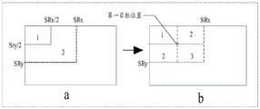
SRCC: the area of the transform coefficients to be scanned in a transform coefficient matrix is determined by (SRx, SRy), where SRx is the abscissa of the rightmost non-zero coefficient in the transform coefficient matrix and SRy is the ordinate of the bottommost non-zero coefficient in the transform coefficient matrix. Only the transform coefficients in the scanning area determined by (SRx, SRy) need to be coded and decoded, and the coefficients outside the scanning area are all 0, so that coding and decoding are not needed.
The general flow of video coding is described next. Referring to fig. 1 (a), taking video coding as an example, video coding generally includes processes of prediction, transformation, quantization, entropy coding, and the like, and further, the coding process can be implemented according to the framework of fig. 1 (b).
The prediction can be divided into intra-frame prediction and inter-frame prediction, wherein the intra-frame prediction is to predict a current uncoded block by using surrounding coded blocks as references, and effectively remove redundancy on a spatial domain. Inter-frame prediction is to use neighboring coded pictures to predict the current picture, effectively removing redundancy in the temporal domain.
The transformation is to transform an image from a spatial domain to a transform domain and to represent the image by using transform coefficients. Most images contain more flat areas and slowly-changing areas, the images can be converted from the dispersed distribution in a space domain into the relatively concentrated distribution in a transform domain through proper transformation, the frequency domain correlation among signals is removed, and code streams can be effectively compressed by matching with a quantization process.
Entropy coding is a lossless coding method that converts a series of element symbols into a binary code stream for transmission or storage, and the input symbols may include quantized transform coefficients, motion vector information, prediction mode information, transform quantization related syntax, and the like. Entropy coding can effectively remove redundancy of the symbols of the video elements.
The above is introduced by taking encoding as an example, the video decoding and the video encoding process are opposite, that is, the video decoding generally includes processes of entropy decoding, prediction, inverse quantization, inverse transformation, filtering, and the like, and the implementation principle of each process is the same as or similar to that of entropy encoding.
Currently, entropy coding can be implemented by using SRCC technology, which can determine a scanning area to be scanned in a transform coefficient matrix of a current block to be coded by using (SRx, SRy) to determine a scanning area to be scanned in the transform coefficient matrix by determining an abscissa SRx of a rightmost non-zero coefficient in the transform coefficient matrix and an ordinate SRy of a bottommost non-zero coefficient in the transform coefficient matrix, and coding the transform coefficient in the determined scanning area of (SRx, SRy).
In an embodiment provided by the present application, when SRCC is used for decoding, context models of significant flag, GT1flag, and GT2flag may be determined according to the number of relevant flags of partial transform coefficients that have been encoded or decoded in a scanning order, and may be grouped according to the relative position of the transform coefficients in a scanning area, the size of the current block, and the channel, where significant flag, GT1flag, and GT2flag may be divided into a luminance channel and a chrominance channel, and specifically, see table 1 below. For example, the luma channel of the significant flag may be divided into three types of context model sets according to the size of the current block, each type of context model set includes 13 types of context models, and each type of context model set may be further grouped according to the relative positions of the transform coefficients in the scan region, so that one context model may be determined for encoding or decoding the luma channel of the significant flag according to the number of non-zero transform coefficients of 5 transform coefficients that have been encoded or decoded in the scan order. For the chroma channel of the significant flag, the context model sets may be grouped according to the relative positions of the transform coefficients in the scan region, and then one context model may be determined according to the number of non-zero transform coefficients of 5 transform coefficients that have been encoded or decoded in the scan order, for encoding or decoding the chroma channel of the significant flag. For another example, for the luminance channel of the GT1flag or the GT2flag, the transform coefficients may be grouped according to the relative positions of the transform coefficients in the scan region, and then a context model may be determined according to the number of non-zero transform coefficients of 5 transform coefficients that have been encoded or decoded in the scan order, for encoding or decoding the luminance channel of the GT1flag or the GT2 flag. For the chroma channel of the GT1flag or the GT2flag, a context model may be determined according to the number of non-zero transform coefficients of 5 transform coefficients that have been encoded or decoded in the scanning order, and used to encode or decode the chroma channel of the GT1flag or the GT2 flag.
Next, a brief description will be given of an implementation environment related to the embodiments of the present application.
The decoding method and the encoding method provided by the embodiment of the application can be executed by an electronic device, and the electronic device can have a function of compressing, encoding or decoding any image or video image. In some embodiments, the electronic device may be a notebook computer, a tablet computer, a desktop computer, a portable computer, and the like, which is not limited in this application.
After the words and implementation environments related to the embodiments of the present application are introduced, the decoding method and the encoding method provided by the embodiments of the present application will be described in detail with reference to the accompanying drawings.
Firstly, the coding process is introduced: the current block obtains a predicted value after prediction, the original value of the current block subtracts the predicted value to obtain a residual error of the current block, the residual error is transformed and quantized to obtain a transform coefficient, if all the transform coefficients of the current block are zero, the cbf flag position of the current block is zero, and the transform coefficient of the current block does not need to be coded. Otherwise, the cbf flag position of the current block is 1, if the encoding end sequence head enables the SRCC, determining the scanning area of the current block, encoding the coordinate values of the SRx and SRy, and encoding each transformation coefficient in sequence from the lower right corner to the upper left corner of the scanning area based on the scanning sequence, wherein the information required by each transformation coefficient comprises at least one of a significant flag, a GT1flag, a GT2flag, a remaining level and a sign. And entropy coding information such as the SRCC enabling zone bit, the transformation coefficient of the current block, the cbf zone bit and the like to obtain a binary code stream.
In an embodiment, the decoding process generally includes: and receiving a code stream, analyzing a cbf flag bit of the current block, wherein the cbf is equal to 0, which means that all transform coefficients of the current block are 0, and inverse quantization and inverse transform operations are not required, so that a residual error of the current block is also 0, and a reconstructed value of the current block is a predicted value of the current block. If the cbf flag bit is 1, if the code stream sequence header analyzes that the current sequence uses the SRCC technology, continuously analyzing the coordinates SRx and SRy of the scanning area of the current block, then determining the scanning area by the SRx and SRy, and decoding each transformation coefficient in sequence from the lower right corner to the upper left corner of the scanning area based on the scanning sequence, wherein the information required to be decoded by each transformation coefficient comprises at least one of a significant flag, a GT1flag, a GT2flag, a rounding level and a sign. And obtaining the transform coefficient of the current block after entropy decoding, obtaining the residual error of the current block through inverse quantization and inverse transform, and adding the residual error and the predicted value to obtain the reconstructed value of the current block.
Referring to fig. 2, which is described in detail by taking decoding as an example, fig. 2 is a flowchart of a decoding method provided by an embodiment of the present application, where the method may be executed by the electronic device, and the method may include the following steps;
step 201: and acquiring the code stream of the current block.
The current block may be any image block in the image to be processed. In implementation, an image to be processed may be divided into different image blocks, and then each image block may be sequentially processed in a certain order. The size and shape of each image block may be set according to a preset partition rule.
The code stream is sent by the encoding end, and the code stream may be a binary code stream, and the code stream may carry some information that the decoding end needs to know in decoding, for example, the code stream may carry information of an encoding mode used by the encoding end, a size of the current block, and the like.
Step 202: when the current block is determined to adopt the SRCC, target position coordinate information is obtained from the code stream, the target position coordinate information is composed of a first coordinate value and a second coordinate value, the first coordinate value is an abscissa of a nonzero coefficient with the largest abscissa absolute value in nonzero coefficients included in the transformation coefficient of the current block, and the second coordinate value is an ordinate of a nonzero coefficient with the largest ordinate absolute value in the nonzero coefficients included in the transformation coefficient of the current block.
As an example, before determining the encoding mode of the current block, it may be determined whether there is a non-zero transform coefficient among the transform coefficients of the current block. For example, the encoding end may carry a flag bit in the code stream to indicate whether all transform coefficients of the current block are zero or not by the flag bit. For example, the flag may be a cbf flag, and when the cbf flag carried by the code stream is 0, it may indicate that all transform coefficients of the current block are zero, in which case it may not be necessary to decode the transform coefficients of the current block. When the cbf flag is 1, it indicates that there is a non-zero transform coefficient in the current block, in which case the transform coefficient of the current block needs to be decoded.
As an example, the encoding mode adopted by the encoding end may be determined before decoding. When the encoding end adopts the SRCC for entropy encoding, the code stream may carry a flag bit indicating the SRCC, so that, for the decoding end, it may be determined that the current block adopts the SRCC according to the flag bit in the code stream.
In the case where the encoding mode of the current block is determined to be SRCC, a scan area corresponding to the transform coefficient may be determined by the abscissa SRx (first coordinate value) of the rightmost non-zero transform coefficient among the transform coefficients of the current block and the ordinate SRy (second coordinate value) of the bottommost non-zero transform coefficient among the transform coefficients. As an example, the coordinate system may be established with a certain vertex of the current block as an origin, and as shown in fig. 3, the coordinate system is established with an upper left vertex of the current block as an origin in the present embodiment. Based on this, the decoding end may determine the target scanning area (the rectangular frame in fig. 3 may be determined by obtaining the target position coordinates formed by SRx and SRy) by obtaining the information of SRx and SRy in the code stream, and as shown in fig. 4, the coordinate values of the positions of all transform coefficients in the target scanning area are all greater than zero. Wherein, the positions corresponding to the SRx and SRy are the target positions corresponding to the target scanning area.
It should be noted that the target scan area may be different according to the distribution of the non-zero transform coefficients, for example, the target scan area may be a partial area of the current block or may be a whole area of the current block. Wherein the transform coefficients in the region of the current block other than the target scan region are all zero, and some transform coefficient or coefficients inside the target scan region may be zero.
Step 203: and determining a context model of a flag bit to be decoded of the coefficient to be decoded aiming at the coefficient to be decoded in a target scanning area of the current block, wherein the target scanning area is a scanning area determined based on the target position coordinate information, and the context model is determined at least according to the target position coordinate information.
The coefficients to be decoded are transform coefficients to be decoded obtained according to a scanning order, that is, the target scanning area may be scanned according to a certain order in the decoding process, for example, as shown in fig. 3, the scanning order may be a reverse zigzag scanning from a lower right corner to an upper left corner. When one transform coefficient is scanned, the transform coefficient is determined as a coefficient to be decoded, and then the flag bit to be decoded of the coefficient to be decoded can be decoded according to the method provided by the embodiment of the application.
The flag bit to be decoded is at least one of a first flag bit, a second flag bit and a third flag bit. The first flag bit is used to indicate whether the transform coefficient is non-zero. The second flag is used to indicate whether the absolute value of the transform coefficient is greater than 1. The third flag is used to indicate whether the absolute value of the transform coefficient is greater than 2.
For example, the first flag is a significant flag, the second flag is a GT1flag, and the third flag is a GT2 flag. That is to say, the transform coefficient to be decoded needs at least one flag bit for indicating the coefficient to be decoded, that is, the coefficient to be decoded may be indicated by one flag bit or may be indicated by a plurality of flag bits. For example, if the coefficient to be decoded is 1, a significant flag is required for indicating that the coefficient to be decoded is non-zero, and a GT1flag is required for indicating that the magnitude of the coefficient to be decoded is 1 or less. If the coefficient to be decoded is 0, the significant flag is only needed to indicate that the coefficient to be decoded is zero.
At least the flag significant flag is generally required for indicating whether the coefficient to be decoded is zero or not. As an example, when the coefficient to be decoded is the last transform coefficient to be decoded in the current block and all transform coefficients decoded in the scanning order before are zero, the coefficient to be decoded may be determined to be non-zero due to the presence of a non-zero transform coefficient in the current block, and therefore, the flag significant flag may not be decoded.
It should be noted that, of course, the syntax element for indicating a transform coefficient may further include other flags and/or parameters, for example, a fourth flag and/or a variable, the fourth flag may be used to indicate whether the non-zero transform coefficient is positive or negative, the variable may be used to indicate the remaining part of the non-zero transform coefficient with a magnitude greater than 2, wherein the fourth flag and the variable may be coded and decoded in other ways, and thus, the description of the embodiment of the present application is not repeated here.
As described above, coding and decoding of transform coefficients may be implemented by coding and decoding a syntax element for indicating transform coefficients, wherein at least one flag bit in the syntax element may be coded and decoded by a context model, and in general, each flag bit may support multiple different context models for coding and decoding. For example, the flag flags significant flag, GT1flag and GT2flag correspond to the number of context models as shown in table 1 below.
TABLE 1

It should be noted that the context model corresponding to each flag bit may be divided into a context model corresponding to a luminance component and a context model corresponding to a chrominance component, and the determining manners of the context models corresponding to the luminance component and the chrominance component may be the same or different.
As an example, the context models corresponding to the flag bits can be classified into multiple types of context model sets according to a certain rule. Taking the flag significant flag as an example, the context models corresponding to the luminance components are 39 types, and the context models can be divided into three types of context model sets, wherein each type of context model set includes 13 types of context models. As an example, for any type of context model set, the context model set may be further divided into a plurality of context model subsets, for example, each type of context model set may be divided into two context model subsets, where each context model subset includes 6 context models. It should be noted that the 1 transform coefficient in the lower right corner of the target scan area may use a separate context model.
Therefore, each flag bit corresponds to a plurality of context models, and therefore, it is necessary to determine which context model is used to decode the coefficient to be decoded in the decoding process. In the embodiment of the present application, the context model is determined at least according to the target position coordinate information, and a specific implementation manner of the context model may include one of the following possible implementation manners:
in a first mode, the context model of the flag bit to be decoded of the coefficient to be decoded is determined at least according to the area of the target scanning region, which is determined according to the target position coordinate information.
As described above, the target position coordinate information includes the first coordinate value and the second coordinate value, and thus the area of the scanning area can be determined according to the first coordinate value and the second coordinate value. For example, the area of the current target scan region is determined by SRx and SRy, and assuming that the area of the scan region is ScanArea, ScanArea is (SRx +1) × (SRy + 1).
As an example, the specific implementation that the context model of the flag bit to be decoded of the coefficient to be decoded is determined according to at least the area of the target scanning region may include: when the area of the target scanning area is smaller than or equal to a first area threshold value, the context model is selected from a first type upper and lower model set, and when the area of the target scanning area is larger than the first area threshold value, the context model is selected from a second type upper and lower model set.
The first area threshold may be set according to actual situations, for example, may be set to any value between 1 and 1024, for example, 2,4,8,16, and the like.
The classification rules of the first type context model and the second type context model can be set according to actual conditions.
That is, when the context model corresponding to the flag bit to be decoded is divided into the first type context model set and the second type context model set according to the rule, it may be determined whether the context model of the flag bit to be decoded is selected from the first type context model set or the second type context model set according to the size relationship between the scanning area and the first area threshold.
For example, the first area threshold is set to be 4, when ScanArea is less than or equal to 4, the context model of the flag bit to be decoded is determined to be selected from the first type context model set, and when ScanArea is more than 4, the context model of the flag bit to be decoded is determined to be selected from the second type context model set.
The above is an example in which when ScanArea is 4, the context model determining the flag bit to be decoded is selected from the second type context model set. In another embodiment, when ScanArea is 4, it may be further determined that the context model of the flag bit to be decoded is selected from the first type context model set. For example, the first area threshold is set to be 4, when ScanArea <4, the context model for determining the flag bit to be decoded is selected from the first type context model set, and when ScanArea ≧ 4, the context model for determining the flag bit to be decoded is selected from the second type context model set.
As another example, the context model is selected from a first type of context model set when the area of the target scanning region is equal to or less than a first area threshold, the context model is selected from a second type of context model set when the area of the target scanning region is greater than the first area threshold and equal to or less than a second area threshold, and the context model is selected from a third type of context model set when the area of the target scanning region is greater than the second area threshold.
The first area threshold and the second area threshold may be set according to actual conditions, for example, may be set to any value between 1 and 1024, such as 2,4,8,16, and the like. It should be noted that the first area threshold should be less than the second area threshold.
When the context model corresponding to the flag bit to be decoded is divided into a first type context model set, a second type context model set and a third type context model set according to rules, which type of context model set the context model of the flag bit to be decoded is selected from can be determined according to the size relationship between the scanning area and the first area threshold and the second area threshold.
For example, setting the first area threshold to be 4 and the second area threshold to be 16, when ScanArea ≦ 4, determining that the context model of the flag bit to be decoded is selected from the first type context model set, and when ScanArea > 4 and ScanArea ≦ 16, determining that the context model of the flag bit to be decoded is selected from the second type context model set. When ScanArea > 16, the context model of the flag bit to be decoded is selected from the third type context model set.
In the above, it is exemplified that the context model of the flag bit to be decoded is determined to be selected from the first type context model set when ScanArea is 4, and in another embodiment, it may also be determined that the context model of the flag bit to be decoded is selected from the second type context model set when ScanArea is 4. Similarly, for ScanArea ═ 16, it may also be determined that the context model of the flag bit to be decoded is selected from the third type context model set.
As another example, the first area threshold is set to 4, the second area threshold is set to 16, when ScanArea <4, the context model for the flag bit to be decoded is selected from the first type context model set, and when ScanArea ≧ 4 and ScanArea <16, the context model for the flag bit to be decoded is selected from the second type context model set. When ScanArea ≧ 16, it is determined that the context model of the flag bit to be decoded is selected from the third type context model set.
As an example, the context models of the flag bits to be decoded may also be divided into context model sets larger than three types, that is, the flag bits to be decoded may also correspond to four types of context model sets, five types of context model sets, and so on, and at this time, more area thresholds may be set for grouping, and the principle is similar to the above, and will not be described in detail here.
In a second approach, the context model is determined based at least on the size of the target scanning area, which is determined based on the target position coordinate information.
The size of the target scanning area may be represented by a length and a width, or the size of the target scanning area may be represented by a length, or the size of the target scanning area may be represented by a width. In this embodiment, the size of the scan area may be determined by the first coordinate value SRx and the second coordinate value SRy, and if the size of the target scan area is ScanSize, the ScanSize may be SRx SRy, or the ScanSize may be SRx, or the ScanSize may be SRy, or the ScanSize may be min (SRx, SRy), according to the foregoing description.
As an example, the context model is selected from a first type of context model set when the size of the target scanning area is equal to or less than a first size threshold, and the context model is selected from a second type of context model set when the size of the target scanning area is greater than the first size threshold.
The first size threshold may be set according to practical situations, such as 2,4,8, and the like.
When the context model corresponding to the flag bit to be decoded is divided into a first class context model set and a second class context model set according to a rule, whether the context model of the flag bit to be decoded is selected from the first class context model set or the second class context model set can be determined according to the size relationship between the size of the scanning area and the first size threshold.
For example, assuming that the first size threshold is 4, when ScanSize ≦ 4, the context model for determining the flag bit to be decoded is selected from the first class of context model set. When ScanSize > 4, the context model of the flag bit to be decoded is selected from the second type context model set.
The above is an example of determining that the context model of the flag bit to be decoded is selected from the first type of context model set when ScanSize is 4, and in another embodiment, when ScanSize is 4, it may also be determined that the context model of the flag bit to be decoded is selected from the second type of context model set.
For another example, assuming that the first size threshold is 4, when ScanSize <4, the context model for determining the flag bit to be decoded is selected from the first type context model set. When ScanSize is larger than or equal to 4, the context model of the flag bit to be decoded is selected from the second type context model set.
As another example, the context model is selected from a first type of context model set when the size of the target scanning area is equal to or less than a first size threshold, the context model is selected from a second type of context model set when the size of the target scanning area is greater than the first size threshold and equal to or less than a second size threshold, and the context model is selected from a third type of context model set when the size of the target scanning area is greater than the second size threshold.
The first size threshold and the second size threshold may be set according to practical situations, for example, may be set to be 2,4,8, and the like, and the first size threshold should be smaller than the second size threshold.
When the context model corresponding to the flag bit to be decoded is divided into a first type context model set, a second type context model set and a third type context model set according to rules, the context model of the flag bit to be decoded can be determined to be selected from the first type context model set according to the size relationship between the size of the scanning area and the size of the first size threshold and the size of the second size threshold.
For example, setting the first size threshold to be 2 and the second size threshold to be 8, when ScanSize ≦ 2, the context model of the flag bit to be decoded is selected from the first class of context model set. When ScanSize > 2 and ScanSize ≦ 8, the context model for the flag bit to be decoded is selected from the second type of context model set. When ScanSize > 8, the context model of the flag bit to be decoded is selected from the third type context model set.
In the above, the context model of the flag bit to be decoded is selected from the first type of context model set when ScanSize is 2, and in another embodiment, it may be further determined that the context model of the flag bit to be decoded is selected from the second type of context model set when ScanSize is 2. Similarly, when ScanSize ═ 8, it may also be determined that the context model of the flag bit to be decoded is selected in the third type context model set.
For another example, when ScanSize <2, the context model of the flag bit to be decoded is selected from the first type context model set. When ScanSize is larger than or equal to 2 and ScanSize is less than 8, the context model of the flag bit to be decoded is selected from the second type context model set. When ScanSize ≧ 8, the context model of the flag bit to be decoded is selected in the third type context model set.
It should be noted that, when the size of the target scanning area can be represented by a length and a width, when comparing with the first size threshold or the second size threshold, the length and the width need to be respectively compared with the first size threshold, and the length and the width need to be respectively compared with the second size threshold, for example, when the first size threshold is 2, it needs to be compared whether the length of the target scanning area is less than 2, and whether the width of the target scanning area is less than 2, and so on.
As an example, the context models of the flag bits to be decoded may also be divided into more than three types of context model sets, that is, the flag bits to be decoded may also correspond to four types of context model sets, five types of context model sets, and so on, and at this time, more size thresholds may be set for grouping, and the principle is similar to the above and will not be described in detail here.
In a third mode, the context model is determined at least from the short side of the target scanning area, which is determined from the target position coordinate information.
In this embodiment, the target scanning area can be determined by the first coordinate value SRx and the second coordinate value SRy, and the short side of the target scanning area is represented by ScanM, where it should be noted that the length of the short side can be represented by a fixed value added to the coordinate values, for example, when SRx +1 and SRy +1 are used to represent the side length of the target scanning area, ScanM is min (SRx +1, SRy + 1).
As an example, when the short edge of the target scanning area is less than or equal to a first short edge threshold, the context model is selected from a first type of context model set, and when the short edge of the target scanning area is greater than the first short edge threshold, the context model is selected from a second type of context model set.
The first short edge threshold may be set according to actual situations, such as 2,4,8, and the like.
When the context model corresponding to the flag bit to be decoded is divided into a first class of context model set and a second class of context model set according to rules, whether the context model of the flag bit to be decoded is selected from the first class of context model set or the second class of context model set can be determined according to the size relationship between the short edge of the target scanning area and the first short edge threshold.
For example, a first short edge threshold is set to 4, and when ScanM is less than or equal to 4, the context model of the flag bit to be decoded is determined to be selected from the first type context model set. When ScanM is more than 4, the context model of the flag bit to be decoded is selected from the second type context model set.
In the above, it is exemplified that the context model of the flag bit to be decoded is determined to be selected from the first type context model set when ScanM is 4, and in another embodiment, it may also be determined that the context model of the flag bit to be decoded is selected from the second type context model set when ScanM is 4.
For another example, the first short edge threshold is set to 4, and when ScanM <4, the context model for determining the flag bit to be decoded is selected from the first type context model set. When ScanM is more than or equal to 4, the context model of the flag bit to be decoded is selected from the second type context model set.
As another example, the context model is selected from a first type of context model set when the short edge of the target scanning area is equal to or less than a first short edge threshold, the context model is selected from a second type of context model set when the short edge of the target scanning area is equal to or less than a second short edge threshold, and the context model is selected from a third type of context model set when the short edge of the target scanning area is equal to or more than the second short edge threshold.
The first short edge threshold and the second short edge threshold may be set according to actual situations, for example, may be set to 2,4,8, and the like, and the first short edge threshold should be smaller than the second short edge threshold.
When the context model corresponding to the flag bit to be decoded is divided into a first type context model set, a second type context model set and a third type context model set according to rules, the context model of the flag bit to be decoded can be determined to be selected from the first type context model set according to the size relationship between the short edge of the target scanning area and the threshold value of the first short edge and the threshold value of the second short edge.
For example, setting the first short edge threshold to be 2 and the second short edge threshold to be 8, when ScanM ≦ 2, the context model of the flag bit to be decoded is selected from the first class of context model set. When ScanM is more than 2 and ScanM is less than or equal to 8, the context model of the flag bit to be decoded is selected from the second type context model set. When ScanM > 8, the context model of the flag bit to be decoded is selected from the third type context model set.
In the above, for example, when ScanM is 2, the context model of the flag bit to be decoded is selected in the first type context model set, and in another embodiment, when ScanM is 2, it may also be determined that the context model of the flag bit to be decoded is selected in the second type context model set. Similarly, when ScanM is 8, it may also be determined that the context model of the flag bit to be decoded is selected from the third type context model set.
For example, when ScanM <2, the context model of the flag bit to be decoded is selected from the first type context model set. When ScanM is more than or equal to 2 and ScanM is less than 8, the context model of the flag bit to be decoded is selected from the second type context model set. When ScanM is more than or equal to 8, the context model of the flag bit to be decoded is selected from the third type context model set.
As an example, the context models of the flag bits to be decoded may also be divided into more than three types of context model sets, that is, the flag bits to be decoded may also correspond to four types of context model sets, five types of context model sets, and so on, and at this time, more short edge thresholds may be set for grouping, the principle is similar to the above, and will not be described in detail here.
In a fourth aspect, the context model is determined based on a linear relation that is satisfied by at least the coordinate values of the target position coordinate information.
As an example, when the coordinate value of the target position coordinate information satisfies the linear relation a × SRx + b × SRy + c ≦ n1, the context model is selected from a first class of context model set, and when the coordinate value of the target position coordinate information satisfies the linear relation a × SRx + b × SRy + c > n1, the context model is selected from a second class of context model set, where a, b, and c are constants, SRx is the first coordinate value, and SRy is the second coordinate value.
Wherein n1 can be 2,4,8, etc., a can be 1, b can be 1, c can be 0 or 2.
For example, when n1 is 2, a is 1, b is 1, and c is 0, the context model of the flag bit to be decoded is selected in the first type context model set when SRx + SRy ≦ 2, and the context model of the flag bit to be decoded is selected in the second type context model set when SRx + SRy > 2.
In the above, it is exemplified that the context model for determining the flag bit to be decoded is selected from the first type context model set when the linear relation a × SRx + b × SRy + c is n1 that is satisfied by the coordinate value of the target position coordinate information. In another embodiment, when the coordinate value of the target position coordinate information satisfies the linear relation a × SRx + b × SRy + c — n1, it may be further determined that the context model of the flag bit to be decoded is selected from the second type context model set.
For example, when the coordinate value of the target position coordinate information satisfies the linear relation a × SRx + b × SRy + c < n1, the context model is selected from a first class of context model set, and when the coordinate value of the target position coordinate information satisfies the linear relation a × SRx + b SRy + c ≧ n1, the context model is selected from a second class of context model set, where a, b, and c are constants, SRx is the first coordinate value, and SRy is the second coordinate value.
When the context model corresponding to the flag bit to be decoded is divided into a first class context model and a second class context model according to rules, which class of context model set the context model of the flag bit to be decoded is selected from can be determined according to the magnitude relation between the sum determined after the linear combination of the first coordinate and the second coordinate of the target scanning area and n 1.
As another example, the context model is selected from a first class of context model set when the coordinate values of the target position coordinate information satisfy the linear relationship a x SRx + b x SRy + c ≦ n1, the context model is selected from a second class of context model set when the coordinate values of the target position coordinate information satisfy the linear relationship n1< a SRx + b x SRy + c ≦ n2, and the context model is selected from a third class of context model set when the coordinate values of the target position coordinate information satisfy the linear relationship a x SRx + b SRy + c > n2, where a, b, and c are constants, SRx is the first coordinate value, and SRy is the second coordinate value.
Wherein, n1 and n2 can be set according to practical situations, such as 2,4,8, etc., and it should be noted that n1 should be smaller than n 2. a may be 1, b may be 1, and c may be 0 or 2.
When the context models corresponding to the flag bits to be decoded are divided into a first type context model, a second type context model and a third type context model according to rules, the context model of the flag bits to be decoded can be selected from the first type context model set according to the magnitude relation between the sum determined after the linear combination of the first coordinate and the second coordinate of the scanning area and n2 and n 1.
For example, when n1 is 2, n2 is 4, a is 1, b is 1, and c is 0, the context model of the flag to be decoded is selected in the first type of context model set when SRx + SRy ≦ 2, and the context model of the flag to be decoded is selected in the second type of context model set when 2 < SRx + SRy ≦ 4. When SRx + SRy > 4, the context model of the flag bit to be decoded is selected from the third type context model set.
In the above, the context model is selected from the first type of context model set when the linear relation that the coordinate value of the target position coordinate information satisfies is a × SRx + b × SRy + c is n1, and in another embodiment, the context model may be determined to be selected from the second type of context model set when the linear relation that the coordinate value of the target position coordinate information satisfies is a × SRx + b SRy + c is n 1. Similarly, when the linear relation a × SRx + b × SRy + c is n2, it may be determined that the context model is selected from the third type context model set.
For example, when the coordinate value of the target position coordinate information satisfies the linear relation a × SRx + b × SRy + c < n1, the context model is selected from a first class of context model set, when the coordinate value of the target position coordinate information satisfies the linear relation n1 ≦ a × SRx + b × SRy + c < n2, the context model is selected from a second class of context model set, and when the coordinate value of the target position coordinate information satisfies the linear relation a × SRx + b × SRy + c ≧ n2, the context model is selected from a third class of context model set, where a, b, and c are constants, SRx is the first coordinate value, and SRy is the second coordinate value.
Thus, a variety of situations have been described in which the context model is determined based at least on the target location coordinate information.
Step 204: and decoding the zone bit to be decoded according to the context model.
As an example, the context model may be determined from a type of context model set determined according to the number of non-zero coefficients of 5 transform coefficients decoded before the coefficient to be decoded after the type of context model set is determined. After the context model is determined, the flag bit to be decoded can be decoded according to the context model.
As an example, the significant flag corresponding to the transform coefficient for a particular location within the target scanning area may be directly derived without decoding. For example, for the two points (SRx, 0) and (0, SRy), if the transform coefficients on the line segment between the two points (SRx, 0) and (SRx, SRy) are all zero, the significant flag of the transform coefficient at the point (SRx, 0) can be directly derived without decoding. Similarly, if the transform coefficients on the line segment between the two points (0, SRy) and (SRx, SRy) are all zero, the significant flag of the transform coefficient at the point (0, SRy) can be directly derived without decoding.
In the embodiment of the application, a code stream of a current block is obtained, when the current block is determined to adopt the SRCC, target position coordinate information is obtained from the code stream, a target scanning area of the current block is determined based on the target position coordinate information, a context model of a to-be-decoded zone bit of a to-be-decoded coefficient is determined at least according to the target position coordinate information, and the to-be-decoded zone bit is decoded according to the context model. That is, the context model of the flag bit to be decoded is determined according to the target scanning area, so that the grouping mode is matched with the scanning mode of the SRCC technology, and the decoding performance is improved.
It should be noted that the first type context model set, the second type context model set, and the third type context model set are only used for grouping, and the first type context model set, the second type context model set, and the third type context model set are different from the first type context model set, the second type context model set, and the third type context model set in other embodiments.
Referring to fig. 5, fig. 5 is a flowchart illustrating a decoding method according to another exemplary embodiment, which may be performed by the electronic device, and the method may include the following implementation steps:
step 501: and acquiring the code stream of the current block.
The specific implementation of this method can refer to step 201 in the above embodiment of fig. 2, and details are not repeated here.
Step 502: when the current block is determined to adopt the SRCC, target position coordinate information is obtained from the code stream, the target position coordinate information is composed of a first coordinate value and a second coordinate value, the first coordinate value is an abscissa of a nonzero coefficient with the largest abscissa absolute value in nonzero coefficients included in the transformation coefficient of the current block, and the second coordinate value is an ordinate of a nonzero coefficient with the largest ordinate absolute value in the nonzero coefficients included in the transformation coefficient of the current block.
The specific implementation of this method can refer to step 202 in the above embodiment of fig. 2, and details are not repeated here.
Step 503: and determining a context model of a flag bit to be decoded of the coefficient to be decoded aiming at the coefficient to be decoded in a target scanning area of the current block, wherein the target scanning area is a scanning area determined based on the target position coordinate information, and the context model is determined at least according to the target position coordinate information.
As an example, the context model is determined according to at least the target position coordinate information, and the specific implementation manner may be: the context model can also be determined at least according to the coordinate information of the target position and the coordinate value of the position of the coefficient to be decoded.
As an example, the specific implementation of the context model determined according to at least the coordinate information of the target position and the coordinate value of the position of the coefficient to be decoded may include: selecting a class of context model set from a plurality of classes of context model sets according to the target position coordinate information of the target scanning area, wherein each class of context model set comprises a plurality of context model subsets, and selecting one context model subset from the plurality of context model subsets included in the selected class of context model set according to the coordinate value of the position of the coefficient to be decoded, wherein the context model is determined from the selected one context model subset.
That is, a type of context model set may be selected from a plurality of types of context model sets according to the target position coordinate information, and a specific implementation manner of the type of context model set may include any one of the following implementation manners (1) to (4):
(1) and determining the area of the target scanning area according to the target position coordinate information of the target scanning area, and selecting one type of context model set from the multiple types of context model sets according to the area.
For a specific implementation of selecting one type of context model set from the multiple types of context model sets according to the area, refer to the specific implementation of embodiment 2 in which the context model is determined at least according to the area of the target scanning area, which is not described herein again.
(2) And determining the size of the target scanning area according to the target position coordinate information of the target scanning area, and selecting one type of context model set from the multiple types of context model sets according to the size.
For a specific implementation of selecting one type of context model set from the multiple types of context model sets according to the size, reference may be made to the above-mentioned specific implementation of embodiment 2 in which the context model is determined according to at least the size of the target scanning area, and details are not described here.
(3) And determining the short edge of the target scanning area according to the target position coordinate information of the target scanning area, and selecting one type of context model set from the multiple types of context model sets according to the short edge.
For a specific implementation of selecting one type of context model set from the multiple types of context model sets according to the short edge, reference may be made to the specific implementation of the context model determined at least according to the short edge of the target scanning area in embodiment 2 above, and details are not repeated here.
(4) And according to the linear relation, selecting a class of context model set from the multiple classes of context model sets.
For a specific implementation of selecting a class of context model set from multiple classes of context model sets according to the linear relationship, refer to the specific implementation of embodiment 2 described above in which the context model is determined at least according to the linear relationship of the target scanning area, and details are not described here.
Because the context model set of one class can be divided into a plurality of context model subsets according to a certain rule, after the context model set of one class is selected, one context model subset can be selected from the context model set of one class according to the coordinate value of the position of the coefficient to be decoded. As an example, selecting a context model subset from the selected class of context model set according to the coordinate value of the position of the coefficient to be decoded may include the following possible implementations:
in a first mode, coordinate values of a first target position are determined according to the target position coordinate information, and a subset of context models is selected from a selected class of context model set according to the coordinate values of the position of the coefficient to be decoded and the coordinate values of the first target position, wherein the context models are determined from the selected subset of context models. The first target position is located within the target scanning area and excludes the target position indicated by the target position coordinate information.
That is, the first target position may be any position within the target scanning area except the position of the (SRx, SRy) point, and as an example, the first target position may also be determined according to the coordinate value of the target position (i.e. SRx, SRy), for example, the first target position may also be (SRx/2, SRy/2).
As an example, when an abscissa value of a position of the coefficient to be decoded is less than or equal to an abscissa value of the first target position, and an ordinate value of the position of the coefficient to be decoded is less than or equal to an ordinate value of the first target position, a first context model subset is selected from the selected class of context models. And when the abscissa value of the position of the coefficient to be decoded is greater than the abscissa value of the first target position, and the ordinate value of the position of the coefficient to be decoded is greater than the ordinate value of the first target position, selecting a third context model subset from the selected class of context model set, otherwise, selecting a second context model subset from the selected class of context model set.
When the selected context model set can be divided into a first context model subset, a second context model subset and a third context model subset according to rules, the context model of the flag bit to be decoded can be selected from which context model subset according to the magnitude relation between the abscissa value and the ordinate value of the position of the coefficient to be decoded and the abscissa value and the ordinate value of the first target position.
In this embodiment, pos _ x is set as an abscissa of a position of a coefficient to be decoded, pos _ y is set as an ordinate of the position of the coefficient to be decoded, an abscissa of a first target position is set to be 4, and an ordinate of the first target position is set to be 8, as shown in fig. 6(b), when pos _ x is less than or equal to 4 and pos _ y is less than or equal to 8, the coefficient to be decoded is located in a region 1, and it is determined that a context model of a flag bit to be decoded is selected from a first context model subset. When pos _ x > 4 and pos _ y > 8, the coefficient to be decoded is located in region 3, and the context model for which the flag bit to be decoded is determined is selected from the third subset of context models. Otherwise, the coefficient to be decoded is located in region 2, and the context model for determining the flag bit to be decoded is selected from the second subset of context models.
The above is an example in which when pos _ x is less than or equal to 4 and pos _ y is less than or equal to 8, the coefficient to be decoded is located in the region 1, and the context model for determining the flag bit to be decoded is selected from the first context model subset. In another embodiment, the context model for determining the flag bit to be decoded may also be selected from the first subset of context models when pos _ x <4 and pos _ y <8 or pos _ x <4 and pos _ y <8, the coefficient to be decoded is located in region 1.
For example, when pos _ x <4 and pos _ y <8, the coefficient to be decoded is located in region 1, and the context model that determines the flag bit to be decoded is selected from the first subset of context models. When pos _ x is greater than or equal to 4 and pos _ y is greater than or equal to 8, the coefficient to be decoded is located in the region 3, and the context model for determining the flag bit to be decoded is selected from the third subset of context models. Otherwise, the coefficient to be decoded is located in region 2, and the context model for determining the flag bit to be decoded is selected from the second subset of context models.
It should be noted that if the target scan region where the transform coefficient is located is divided into a low frequency region and a non-low frequency region according to the division manner in fig. 6(a), since the non-low frequency region includes a medium frequency region and a high frequency region, the medium frequency region often includes non-zero transform coefficients, and most transform coefficients in the high frequency region are zero, which results in poor context adaptation effect. In the implementation manner of this embodiment, as shown in fig. 6(b), the scanning area where the transform coefficient is located can be more finely divided into a low frequency area, an intermediate frequency area, and a high frequency area, so that context adaptation is facilitated, and decoding efficiency is further improved.
In a second manner, coordinate values of a second target position and a third target position are determined according to the target position coordinate information, a subset of context models is selected from a selected class of context model set according to the coordinate value of the position of the coefficient to be decoded, and the coordinate values of the second target position and the third target position, and the context models are determined from the selected subset of context models.
As an example, when an abscissa value of a position of the coefficient to be decoded is less than or equal to an abscissa value of the second target position, and an ordinate value of the position of the coefficient to be decoded is less than or equal to an ordinate value of the second target position, the first context model subset is selected from the selected one type of context model set. And when the abscissa value of the position of the coefficient to be decoded is greater than the abscissa value of the third target position, and the ordinate value of the position of the coefficient to be decoded is greater than the ordinate value of the third target position, selecting a third context model subset from the selected class of context model set, otherwise, selecting a second context model subset from the selected class of context model set.
The abscissa and the ordinate of the second target position and the third target position may be set according to actual situations, for example, the abscissa and the ordinate may be set to 4,8,16, etc., it should be noted that the abscissa of the second target position should be smaller than the abscissa of the third target position, and the ordinate of the second target position should be smaller than the ordinate of the third target position.
When the selected one type of context model set can be divided into a first context model subset, a second context model subset and a third context model subset according to rules, the context model of the flag bit to be decoded can be determined from which context model subset to be selected according to the magnitude relations between the abscissa and the ordinate of the position of the coefficient to be decoded and the abscissa and the ordinate of the second target position and the third target position.
In this embodiment, let pos _ x be the abscissa of the position of the coefficient to be decoded, pos _ y be the ordinate of the position of the coefficient to be decoded, let the abscissa of the second target position be 4, the ordinate of the second target position be 8, the abscissa of the third target position be 16, and the ordinate of the third target position be 16. As shown in FIG. 7, when pos _ x ≦ 4 and pos _ y ≦ 8, the coefficient to be decoded is located in region 1, the context model that determines the flag bit to be decoded is selected from the first subset of context models. When pos _ x > 16 and pos _ y > 16, the coefficient to be decoded is located in region 3, it is determined that the context model of the flag to be decoded is selected from the third subset of context models. Otherwise, when the coefficient to be decoded is located in the region 2, it is determined that the context model of the flag bit to be decoded is selected from the second subset of context models.
In the above, when pos _ x is less than or equal to 4 and pos _ y is less than or equal to 8, the coefficient to be decoded is located in the region 1, and the context model for determining the flag bit to be decoded is selected from the first context model subset. In another embodiment, the context model for determining the flag bit to be decoded may also be selected from the first subset of context models when pos _ x <4 and pos _ y <8 or pos _ x <4 and pos _ y <8, the coefficient to be decoded is located in region 1. Similarly, it can also be determined that the context model of the flag bit to be decoded is selected from the third subset of context models when the coefficient to be decoded is located in region 3 when pos _ x > 16 and pos _ y > 16 or pos _ x > 16 and pos _ y > 16.
For example, when pos _ x <4 and pos _ y <8, the coefficient to be decoded is located in region 1, the context model that determines the flag bit to be decoded is selected from the first subset of context models. When pos _ x is greater than or equal to 16 and pos _ y is greater than or equal to 16, and the coefficient to be decoded is located in the region 3, determining that the context model of the flag bit to be decoded is selected from the third subset of context models. Otherwise, when the coefficient to be decoded is located in the region 2, it is determined that the context model of the flag bit to be decoded is selected from the second subset of context models.
It should be noted that the selected context model set may also be divided into more than three context model subsets, that is, the selected context model set may also correspond to four context model subsets, five context model subsets, and so on.
As another example, the specific implementation of the context model determined at least according to the target position coordinate information may be: the context model can also be determined according to a linear relation at least satisfied by the coordinate value of the target position and the coordinate value of the position of the coefficient to be decoded.
It should be noted that, the above description is only given by taking an example of selecting a class of context model set from multiple classes of context model sets according to the coordinate value of the target position, and then selecting one context model subset from multiple context model subsets included in the selected class of context model set according to the coordinate value of the position of the coefficient to be decoded.
As an example, the specific implementation of the context model determined according to at least a linear relation that the target position coordinate information and the coordinate value of the position of the coefficient to be decoded satisfy may include: selecting a class of context model set from a plurality of classes of context model sets according to the target position coordinate information of the target scanning area, wherein each class of context model set comprises a plurality of context model subsets, and selecting one context model subset from the plurality of context model subsets contained in the selected class of context model set according to a linear relation satisfied by the coordinate value of the position of the coefficient to be decoded, wherein the context model is determined from the selected one context model subset.
It should be noted that the specific implementation of selecting one type of context model set from the multiple types of context model sets according to the target position coordinate information of the target scanning area may adopt any one of the four manners (1) to (4) in the previous example, and details are not described here.
As an example, according to a linear relation that the coordinate value of the position of the coefficient to be decoded satisfies, a specific implementation manner of selecting one context model subset from a plurality of context model subsets included in the selected context model set may include, but is not limited to, the following possible implementation manners:
in a first mode, when the linear relation satisfied by the coordinate value of the position of the coefficient to be decoded is a × pos _ y + b × pos _ x ≦ c, a first context model subset is selected from the plurality of context model subsets included in the selected context model set. When the coordinate value of the position of the coefficient to be decoded satisfies a linear relation a _ pos _ y + b _ pos _ x > c, selecting a second context model subset from a plurality of context model subsets included in the selected context model set, wherein a and b are constants, pos _ x is an abscissa value of the position of the coefficient to be decoded, and pos _ y is an ordinate value of the position of the coefficient to be decoded.
As an example, a may be a first coordinate value, b may be a second coordinate value, and c is a product of the first coordinate value and the second coordinate value, that is, a ═ SRx, b ═ SRy, and c ═ SRx ═ SRy.
When the selected context model set can be divided into a first context model subset and a second context model subset according to a rule, the context model of the flag bit to be decoded can be determined to be selected from which context model subset according to a linear relation formula satisfied by the coordinate value of the position of the coefficient to be decoded.
For example, as shown in FIG. 8, when SRx _ pos _ y + SRy _ pos _ x ≦ SRx _ SRy, i.e., the coefficient to be decoded is located in region 1, the context model that determines the flag to be decoded is selected from the first subset of context models. When SRx _ pos _ y + SRy _ pos _ x > SRx SRy, i.e. the coefficient to be decoded is located in region 2, the context model determining the flag to be decoded is selected from the second subset of context models.
In the above, when the coordinate value of the position of the coefficient to be decoded satisfies the linear relation a × pos _ y + b × pos _ x ═ c, the first context model subset is selected from the plurality of context model subsets included in the selected context model set. In another embodiment, when the coordinate value of the position of the coefficient to be decoded satisfies the linear relationship a × pos _ y + b × pos _ x ═ c, the second context model subset may be further selected from a plurality of context model subsets included in the selected context model set.
For example, when the coordinate value of the position of the coefficient to be decoded satisfies the linear relation a _ pos _ y + b _ pos _ x < c, the first context model subset is selected from a plurality of context model subsets included in the selected context model set. And when the coordinate value of the position of the coefficient to be decoded satisfies a linear relation a _ pos _ y + b _ pos _ x ≧ c, selecting a second context model subset from a plurality of context model subsets included in the selected context model set, wherein a and b are constants, pos _ x is an abscissa value of the position of the coefficient to be decoded, and pos _ y is an ordinate value of the position of the coefficient to be decoded.
In the second way, when the coordinate value of the position of the coefficient to be decoded satisfies the linear relation a1 × pos _ y + b1 × pos _ x ≦ c1, the first context model subset is selected from the selected context model set. When the coordinate value of the position of the coefficient to be decoded satisfies the linear relation a1 × pos _ y + b1 × pos _ x > c1, and a2 × pos _ y + b2 × pos _ x < c2, selecting a second context model subset from the selected class of context model set, and when the coordinate value of the position of the coefficient to be decoded satisfies the linear relation a2 × pos _ y + b2 × pos _ x ≧ c2, selecting a third context model subset from the selected class of context model set, wherein the a1, b1, a2, b2, c1, and c2 are constants, the c1 is smaller than the c2, the pos _ x is an abscissa value of the position of the coefficient to be decoded, and the pos _ y is an ordinate value of the position of the coefficient to be decoded.
As an example, the a1 and a2 may be both first coordinate values, the b1 and b2 may be both second coordinate values, the c1 is a half of a product between the first coordinate value and the second coordinate value, and the c2 is a product between the first coordinate value and the second coordinate value. That is, a1 ═ a2 ═ SRx, b1 ═ b2 ═ SRy, c1 ═ SRx SRy)/2, and c2 ═ SRx ═ SRy. As another example, a1 ═ 2 × SRx, b1 ═ 2 × SRy, c1 ═ SRx SRy, a2 ═ SRx, b2 ═ SRy, c2 ═ SRx SRy, or a1 ═ 0, b1 ═ 4, c1 ═ SRx, a2 ═ 0, b ═ 2, c2 ═ SRx + 1, or SRx, or a1 ═ 4, b1 ═ 0, c1 ═ SRy, a2 ═ 2, b2 ═ 0, c2 ═ SRy + 1, or SRy may also be provided.
When the selected one type of context model set can be divided into a first context model subset, a second context model subset and a third context model subset according to rules, the context model of the flag bit to be decoded can be determined to be selected from which context model subset according to a linear relation satisfied by the coordinate value of the position of the coefficient to be decoded.
For example, as shown in fig. 9, when SRx _ pos _ y + SRy _ pos _ x ≦ (SRx _ SRy)/2, indicating that the coefficient to be decoded is located in region 1, the context model that determines the flag bit to be decoded is selected from the first subset of context models. When (SRx SRy)/2 < SRx pos _ y + SRy pos _ x < SRx SRy indicates that the coefficient to be decoded is located in region 2, the context model that determines the flag to be decoded is selected from the second subset of context models. When SRx _ pos _ y + SRy _ pos _ x is greater than or equal to SRx _ SRy, indicating that the coefficient to be decoded is located in region 3, the context model that determines the flag bit to be decoded is selected from the third subset of context models.
In the above, for example, when the linear relation formula at the position of the coefficient to be decoded is a1 × pos _ y + b1 × pos _ x ═ c1, the first context model subset is selected from the selected class of context model set, and in another embodiment, when the linear relation formula at the position of the coefficient to be decoded is a1 × pos _ y + b1 × pos _ x ═ c1, the second context model subset may be selected from the selected class of context model set. Similarly, when the coordinate value of the position of the coefficient to be decoded satisfies the linear relation a2 × pos _ y + b2 × pos _ x — c2, the second context model subset may also be selected from the selected class of context model set.
For example, when the coordinate value of the position of the coefficient to be decoded satisfies the linear relation a1 × pos _ y + b1 × pos _ x < c1, a first context model subset is selected from the selected class of context model set. When the coordinate value of the position of the coefficient to be decoded satisfies the linear relation a1 × pos _ y + b1 × pos _ x ≧ c1, and a2 × pos _ y + b2 × pos _ x ≦ c2, selecting a second context model subset from the selected class of context model set, and when the coordinate value of the position of the coefficient to be decoded satisfies the linear relation a2 × pos _ y + b2 × pos _ x > c2, selecting a third context model subset from the selected class of context model set, wherein the a1, b1, a2, b2, c1, and c2 are constants, the c1 is smaller than the c2, the pos _ x is an abscissa value of the position of the coefficient to be decoded, and the pos _ y is an ordinate value of the position of the coefficient to be decoded.
In addition, the selected context model set of one category may also be divided into more than three context model subsets, that is, the selected context model set of one category may also correspond to four context model subsets, five context model subsets, and so on.
It should be noted that, the above description is only given by taking an example of selecting a class of context model set from multiple classes of context model sets according to the target position coordinate information, and then selecting one context model subset from multiple context model subsets included in the selected class of context model set according to the linear relational expression satisfied by the coordinate value of the position of the coefficient to be decoded, in another embodiment, a class of context model set may also be selected from multiple classes of context model sets according to the linear relational expression satisfied by the coordinate value of the position of the coefficient to be decoded, and then selecting one context model subset from multiple context model subsets included in the selected class of context model set according to the target position coordinate information, that is, the order of selection is not limited in the present application.
As an example, the specific implementation that the context model is determined according to at least the target position coordinate information may be: the context model is determined at least according to a linear relation that the coordinate information of the target position, the coordinate value of the position of the coefficient to be decoded and the coordinate value of the position of the coefficient to be decoded satisfy.
As an example, a specific implementation of the context model determined according to at least a linear relation that the target position coordinate information, the coordinate value of the position of the coefficient to be decoded, and the coordinate value of the position of the coefficient to be decoded satisfy may include: selecting a class of context model set from a plurality of classes of context model sets according to the target position coordinate information of the target scanning area, wherein each class of context model set comprises a plurality of context model subsets, and selecting one context model subset from the plurality of context model subsets included in the selected class of context model set according to a linear relation satisfied by the coordinate value of the position of the coefficient to be decoded, the coordinate value of the position of the coefficient to be decoded and the target position coordinate information, wherein the context model is determined from the selected one context model subset.
It should be noted that, a specific implementation of selecting one type of context model set from the multiple types of context model sets according to the target position coordinate information of the target scanning area may adopt any one of the four manners (1) to (4) in the above example, and details are not repeated here.
As an example, according to the linear relationship that the coordinate value of the position of the coefficient to be decoded satisfies, the coordinate value of the position of the coefficient to be decoded, and the coordinate information of the target position, a specific implementation manner of selecting one context model subset from a plurality of context model subsets included in the selected context model set may be: and when the abscissa value of the position of the coefficient to be decoded is less than or equal to a first coordinate threshold value and the ordinate value of the position of the coefficient to be decoded is less than or equal to a second coordinate threshold value, selecting a first context model subset from a plurality of context model subsets included in the selected context model set. And when the coordinate value of the position of the coefficient to be decoded satisfies a linear relation a _ pos _ y + b _ pos _ x > c, selecting a third context model subset from a plurality of context model subsets included in the selected context model set. Otherwise, a second context model subset is selected from a plurality of context model subsets included in the selected context model set, wherein the first coordinate threshold is smaller than the first coordinate value, and the second coordinate threshold is smaller than the second coordinate value.
The first coordinate threshold and the second coordinate threshold may be set according to actual situations, for example, may be set to 2,4,8, and the like. As an example, a may be SRx, b may be SRy, and c may be SRx SRy.
When the selected context model set can be divided into a first context model subset, a second context model subset and a third context model subset according to rules, the context model of the flag bit to be decoded can be determined to be selected from which context model subset according to a linear relation satisfied by the coordinate value of the position of the coefficient to be decoded, the coordinate value of the position of the coefficient to be decoded and the coordinate information of the target position.
For example, the first coordinate threshold is set to be 2, the second coordinate threshold is set to be 4, as shown in fig. 10, when pos _ x is less than or equal to 2 and pos _ y is less than or equal to 4, the coordinate indicating the position of the coefficient to be decoded is located in the region 1, the context model determining the flag bit to be decoded is selected from the first context model subset, when SRx _ pos _ y + SRy × pos _ x > SRx SRy, the coordinate indicating the position of the coefficient to be decoded is located in the region 3, and the context model determining the flag bit to be decoded is selected from the third context model subset. Otherwise, the coordinate indicating the position of the coefficient to be decoded is located in the region 2, and the context model determining the flag bit to be decoded is selected from the second context model subset.
In the above, when pos _ x is 2 and pos _ y is 4, the first context model subset is selected from a plurality of context model subsets included in the selected context model set, and in another embodiment, the following cases may be further included: when pos _ x is less than 2 and pos _ y is less than 4, the context model of the flag bit to be decoded is determined to be selected from the first context model subset, and when SRx _ pos _ y + SRy _ pos _ x is more than or equal to SRx _ SRy, the context model of the flag bit to be decoded is determined to be selected from the third context model subset. Otherwise, it is determined that the context model of the flag to be decoded is selected from the second subset of context models.
It should be noted that, the above description is given by taking an example in which one context model subset is selected from a plurality of context model subsets included in a selected context model set according to a linear relational expression that a coordinate value of a position of the coefficient to be decoded satisfies, the coordinate value of the position of the coefficient to be decoded, and the target position coordinate information. In another embodiment, the context model may further select a subset of context models from a plurality of context model subsets included in the selected class of context model set according to at least one of a linear relation satisfied by the coordinate value of the position of the coefficient to be decoded, and the coordinate information of the target position.
It should be further noted that, the above is exemplified by selecting a class of context model set from multiple classes of context model sets according to the target position coordinate information of the target scanning area, and then selecting a context model subset from the selected class of context model set according to a linear relation that the target position coordinate information, the coordinate value of the position of the coefficient to be decoded, and the coordinate value of the position of the coefficient to be decoded satisfy. In another embodiment, a class of context model set may be selected from the class of context model sets according to a linear relationship that the target position coordinate information, the coordinate value of the position of the coefficient to be decoded, and the coordinate value of the position of the coefficient to be decoded satisfy, and then a context model subset may be selected from the class of context model set according to the target position coordinate information of the target scanning area.
As an example, the specific implementation that the context model is determined according to at least the target position coordinate information may be: the context model is determined at least according to the target position coordinate information and a preset condition met by the current block.
The preset condition may be set according to an actual requirement, and as an example, the preset condition may include, but is not limited to, any of the following conditions:
the first coordinate value or the second coordinate value is zero. Or the product of the first coordinate value and the second coordinate value is smaller than a first coordinate threshold value. Or, the first coordinate value is greater than or equal to a second coordinate threshold value and the second coordinate value is greater than or equal to a third coordinate threshold value. Or the first coordinate value is less than or equal to a second coordinate threshold value or the second coordinate value is less than a third coordinate threshold value.
The first coordinate threshold, the second coordinate threshold and the third coordinate threshold can be set according to actual conditions.
As an example, a first coordinate threshold value is set to be 4, a second coordinate threshold value is set to be 1, and a third coordinate threshold value is set to be 2. That is, the preset condition may be: SRx is 0 or SRy is 0; SRx SRy < 4; SRx is more than or equal to 1, and SRy is more than or equal to 2; SRx is less than or equal to 1 or SRy is less than or equal to 2.
As an example, the specific implementation that the context model is determined according to at least the target position coordinate information and the preset condition satisfied by the current block may include: selecting a class of context model set from a plurality of classes of context model sets according to the target position coordinate information of the target scanning area, wherein each class of context model set comprises a plurality of context model subsets, determining a selection mode according to a preset condition met by the current block, and selecting one context model subset from the plurality of context model subsets included in the selected class of context model set according to the determined selection mode, wherein the context model is determined from the selected one context model subset.
It should be noted that, a specific implementation of selecting one type of context model set from the multiple types of context model sets according to the target position coordinate information of the target scanning area may adopt any one of the four manners (1) to (4) in the above example, and details are not repeated here.
As an example, the specific implementation manner of determining the selection manner according to the preset condition satisfied by the current block, and selecting one context model subset from a plurality of context model subsets included in the selected context model set according to the determined selection manner may be: and when the current block meets a preset condition, selecting a context model subset from a plurality of context model subsets included in the selected context model set according to a linear relation formula met by the coordinate value of the position of the coefficient to be decoded. And when the current block does not meet the preset condition, selecting a context model subset from a plurality of context model subsets included in the selected context model set according to the coordinate value of the position of the coefficient to be decoded and the target position coordinate information.
For example, if the first coordinate value and/or the second coordinate value in the current block satisfy a predetermined condition, such as when SRx is equal to 0, the flag bit to be decoded determines the context model based on a linear combination of pos _ x and pos _ y, and the specific implementation manner thereof can be seen in the above embodiments. Otherwise, the flag bit to be decoded determines the context model based on the positions of pos _ x and pos _ y, and the specific implementation manner of this can be seen in the above embodiments.
In the above example, a type of context model set is selected from a plurality of types of context model sets according to the target position coordinate information of the target scanning area, a selection mode is determined according to a preset condition that the current block satisfies, and a context model subset is selected from the selected type of context model set according to the determined selection mode. In another embodiment, a selection mode may be determined according to a preset condition that the current block satisfies, a class of context model set may be selected from multiple classes of context model sets according to the determined selection mode, and a context model subset may be selected from the class of context model set according to the target position coordinate information of the target scanning area.
The selection mode can be selected according to a linear relation formula which is satisfied by the coordinate value of the position of the coefficient to be decoded; or, selecting according to the coordinate value of the position of the coefficient to be decoded and the coordinate information of the target position.
Step 504: and decoding the zone bit to be decoded according to the context model.
The specific implementation of this method can refer to step 204 in the above embodiment of fig. 2, and details are not repeated here.
In the embodiment of the application, a code stream of a current block is obtained, when the current block is determined to adopt the SRCC, target position coordinate information is obtained from the code stream, a target scanning area of the current block is determined based on the target position coordinate information, a context model of a to-be-decoded zone bit of a to-be-decoded coefficient is determined at least according to the target position coordinate information, and the to-be-decoded zone bit is decoded according to the context model. That is, the context model of the flag bit to be decoded is determined according to the target scanning area, so that the grouping mode is matched with the scanning mode of the SRCC technology, and the decoding performance is improved.
In addition, in this embodiment, a type of context model set may be selected from multiple types of context model sets according to the target scanning area, so as to ensure that the grouping manner is matched with the SRCC scanning manner. And then, selecting a context model subset from the selected class of context model sets according to the position of the coefficient to be decoded in the target scanning area, and further determining a context model of the flag bit to be decoded of the coefficient to be decoded from the selected context model subset, so that the area where the transform coefficient is located is more finely divided into low-frequency, medium-frequency and high-frequency areas, and the decoding efficiency is improved.
It should be noted that the first type context model set, the second type context model set, and the third type context model set are only used for grouping, and the first type context model set, the second type context model set, and the third type context model set are different from the first type context model set, the second type context model set, and the third type context model set in other embodiments.
As an example, the present application further provides a decoding method, which may be performed by the electronic device described above, and the method may include the following steps.
Step A1: and acquiring the code stream of the current block.
The specific implementation manner of this embodiment may refer to step 201 in fig. 2, and details are not repeated here.
Step A2: when the current block is determined to adopt the SRCC, target position coordinate information is obtained from the code stream, the target position coordinate information is composed of a first coordinate value and a second coordinate value, the first coordinate value is an abscissa of a nonzero coefficient with the largest abscissa absolute value in nonzero coefficients included in the transformation coefficient of the current block, and the second coordinate value is an ordinate of a nonzero coefficient with the largest ordinate absolute value in the nonzero coefficients included in the transformation coefficient of the current block.
The specific implementation manner of this embodiment may refer to step 202 in fig. 2, and details are not repeated here.
Step A3: and determining a context model of a flag bit to be decoded of the coefficient to be decoded in a target scanning area of the current block, wherein the target scanning area is a scanning area determined based on the target position coordinate information, and the context model is determined from at least three types of context model sets according to at least coordinate values of the position of the coefficient to be decoded.
The specific implementation manner of the context model determined from at least three types of context model sets at least according to the coordinate value of the position of the coefficient to be decoded can be various.
In a first mode, the context model is determined from at least three types of context model sets according to at least coordinate values of positions of the coefficients to be decoded, and the method includes: and determining a coordinate value of a first target position according to the target position coordinate information, wherein the context model is determined at least according to the coordinate value of the position of the coefficient to be decoded and the coordinate value of the first target position, and the first target position is positioned in the target scanning area and excludes the target position indicated by the target position coordinate information.
That is, the first target position may be any position other than the position of the point (SRx, SRy) in the target scanning area, and as an example, the first target position may also be determined according to the position of the target position, that is, the position of the point (SRx, SRy), for example, the first target position may also be (SRx/2, SRy/2).
As an example, when an abscissa value of a position of the coefficient to be decoded is less than or equal to an abscissa value of the first target position, and an ordinate value of the position of the coefficient to be decoded is less than or equal to an ordinate value of the first target position, the context model is selected from a first type context model set; when the abscissa value of the position of the coefficient to be decoded is greater than the abscissa value of the first target position, and the ordinate value of the position of the coefficient to be decoded is greater than the ordinate value of the first target position, the context model is selected from a third class context model set; otherwise, the context model is selected from a second type of context model set.
When the context models corresponding to the flag bits to be decoded of the coefficients to be decoded can be classified into a first class context model set, a second class context model set and a third class context model set according to rules, which class context model set the context models of the flag bits to be decoded are selected from can be determined according to the magnitude relationship between the abscissa value and the ordinate value of the positions of the coefficients to be decoded and the abscissa value and the ordinate value of the first target positions.
The details of the target scanning area can be seen in fig. 6.
In a second mode, the determining of the context model from at least three types of context model sets according to at least the coordinate value of the position of the coefficient to be decoded includes: and determining coordinate values of a second target position and a third target position according to the coordinate information of the target position, wherein the context model is determined at least according to the coordinate value of the position of the coefficient to be decoded, the coordinate value of the second target position and the coordinate value of the third target position.
As an example, when an abscissa value of a position of the coefficient to be decoded is less than or equal to an abscissa value of the second target position, and an ordinate value of the position of the coefficient to be decoded is less than or equal to an ordinate value of the second target position, the context model is selected from a first type context model set; when the abscissa value of the position of the coefficient to be decoded is greater than the abscissa value of the third target position, and the ordinate value of the position of the coefficient to be decoded is greater than the ordinate value of the third target position, the context model is selected from a third class context model set; otherwise, the context model is selected from a second type of context model set.
The abscissa and the ordinate of the second target position and the third target position may be set according to actual situations, for example, the abscissa and the ordinate may be set to 4,8,16, etc., it should be noted that the abscissa of the second target position should be smaller than the abscissa of the third target position, and the ordinate of the second target position should be smaller than the ordinate of the third target position.
When the context models corresponding to the flag bits to be decoded of the coefficients to be decoded can be classified into a first type context model set, a second type context model set and a third type context model set according to rules, which type of context model set the context models of the flag bits to be decoded are selected from can be determined according to the magnitude relations between the abscissa and the ordinate of the position of the coefficient to be decoded and the abscissa and the ordinate of the second target position and the third target position.
The details of the target scanning area can be seen in fig. 7.
The specific implementation manner of this embodiment may refer to step 203 in fig. 2, and details are not repeated here.
Step A4: and decoding the flag bit to be decoded according to the context model.
The specific implementation manner of this embodiment may refer to step 204 in fig. 2, and details are not repeated here.
In the embodiment of the application, a code stream of a current block is obtained, when the current block is determined to adopt the SRCC, target position coordinate information is obtained from the code stream, a target scanning area of the current block is determined based on the target position coordinate information, a context model of a to-be-decoded zone bit of a to-be-decoded coefficient is determined at least according to the target position coordinate information, and the to-be-decoded zone bit is decoded according to the context model. That is, the context model of the flag bit to be decoded is determined according to the target scanning area, so that the grouping mode is matched with the scanning mode of the SRCC technology, and the decoding performance is improved.
It should be noted that the first type context model set, the second type context model set, and the third type context model set are only used for grouping, and the first type context model set, the second type context model set, and the third type context model set are different from the first type context model set, the second type context model set, and the third type context model set in other embodiments.
As an example, an embodiment of the present application further provides a decoding method, which may be performed by the electronic device described above, and the method may include the following steps.
Step B1: and acquiring the code stream of the current block.
The specific implementation manner of this embodiment may refer to step 201 in fig. 2, and details are not repeated here.
Step B2: when the current block is determined to adopt the coefficient coding SRCC based on the scanning area, acquiring target position coordinate information from the code stream, wherein the target position coordinate information consists of a first coordinate value and a second coordinate value, the first coordinate value is the abscissa of the nonzero coefficient with the largest absolute value of the abscissa in the nonzero coefficients included in the transformation coefficient of the current block, and the second coordinate value is the ordinate of the nonzero coefficient with the largest absolute value of the ordinate in the nonzero coefficients included in the transformation coefficient of the current block.
The specific implementation manner of this embodiment may refer to step 202 in fig. 2, and details are not repeated here.
Step B3: and determining a context model of a flag bit to be decoded of the coefficient to be decoded aiming at the coefficient to be decoded in a target scanning area of the current block, wherein the target scanning area is a scanning area determined based on the target position coordinate information, and the context model is determined at least according to a linear relation satisfied by the coordinate value of the position of the coefficient to be decoded.
The specific implementation manner of the context model determined at least according to the linear relation satisfied by the coordinate value of the position of the coefficient to be decoded can be various.
In the first mode, when the coordinate value of the position of the coefficient to be decoded satisfies the linear relation a _ pos _ y + b _ pos _ x ≦ c, the context model is selected from the first class of context model set; when the coordinate value of the position of the coefficient to be decoded satisfies the linear relation a _ pos _ y + b _ pos _ x > c, the context model is selected from the second type context model set; wherein a and b are constants, pos _ x is an abscissa value of the position of the coefficient to be decoded, and pos _ y is an ordinate value of the position of the coefficient to be decoded.
Wherein, the a is the first coordinate value, the b is the second coordinate value, and the first value is the product of the first coordinate value and the second coordinate value.
When the context model corresponding to the flag bit to be decoded of the coefficient to be decoded can be divided into a first class context model set and a second class context model set according to rules, the context model of the flag bit to be decoded can be determined from which class of context model set to select according to a linear relation satisfied by the coordinate value of the position of the coefficient to be decoded.
The details of the target scanning area can be seen in fig. 8.
In the second way, when the coordinate value of the position of the coefficient to be decoded satisfies the linear relation a1 × pos _ y + b1 × pos _ x ≦ c1, the context model is selected from the first class of context model set; when the coordinate value of the position of the coefficient to be decoded satisfies the linear relation a1 × pos _ y + b1 × pos _ x > c1, and a2 × pos _ y + b2 × pos _ x is not more than c2, the context model is selected from the second type context model set; when the coordinate value of the position of the coefficient to be decoded satisfies the linear relation a2 × pos _ y + b2 × pos _ x > c2, the context model is selected from a third class of context model set; wherein a1, b1, a2, b2, c1 and c2 are constants, c1 is smaller than c2, pos _ x is an abscissa value of the position of the coefficient to be decoded, and pos _ y is an ordinate value of the position of the coefficient to be decoded.
Wherein, the a1 and a2 are the first coordinate values, the b1 and b2 are the second coordinate values, the c1 is half of the product of the first coordinate value and the second coordinate value, and the c2 is the product of the first coordinate value and the second coordinate value.
When the context models corresponding to the flag bits to be decoded of the coefficients to be decoded can be classified into a first class context model set, a second class context model set and a third class context model set according to rules, which class of context model set the context models of the flag bits to be decoded are selected from can be determined according to a linear relation satisfied by the coordinate values of the positions of the coefficients to be decoded.
The details of the target scanning area can be seen in fig. 9.
Therefore, a specific implementation manner of determining the context model according to a linear relation satisfied by the coordinate value of the position of the coefficient to be decoded is introduced.
Further, the context model is determined according to at least a linear relation that the coordinate value of the position of the coefficient to be decoded satisfies, the coordinate value of the position of the coefficient to be decoded, and the target position coordinate information, and the specific implementation process includes: when the abscissa value of the position of the coefficient to be decoded is less than or equal to a first coordinate threshold value, and the ordinate value of the position of the coefficient to be decoded is less than or equal to a second coordinate threshold value, the context model is selected from a first class of context model sets; otherwise, when the coordinate value of the position of the coefficient to be decoded satisfies the linear relation a _ pos _ y + b _ pos _ x > c, the context model is selected from the third type of context model set; otherwise, the context model is selected from the second type context model set; the first coordinate threshold is smaller than the first coordinate value, and the second coordinate threshold is smaller than the second coordinate value.
When the context models corresponding to the flag bits to be decoded of the coefficients to be decoded can be classified into a first class context model set, a second class context model set and a third class context model set according to rules, which class context model set the context models of the flag bits to be decoded are selected from can be determined according to a linear relation satisfied by the coordinate values of the positions of the coefficients to be decoded, the coordinate values of the positions of the coefficients to be decoded and the coordinate information of the target position.
The details of the target scanning area can be seen in fig. 10.
The specific implementation manner of this embodiment may refer to step 203 in fig. 2, and details are not repeated here.
In addition, the selected context model set of one category may also be divided into more than three context model sets, that is, the selected context model set of one category may also correspond to four context model sets, five context model sets, and so on.
Step B4: and decoding the flag bit to be decoded according to the context model.
The specific implementation manner of this embodiment may refer to step 204 in fig. 2, and details are not repeated here.
In the embodiment of the application, a code stream of a current block is obtained, when the current block is determined to adopt the SRCC, target position coordinate information is obtained from the code stream, a target scanning area of the current block is determined based on the target position coordinate information, a context model of a to-be-decoded zone bit of a to-be-decoded coefficient is determined at least according to the target position coordinate information, and the to-be-decoded zone bit is decoded according to the context model. That is, the context model of the flag bit to be decoded is determined according to the target scanning area, so that the grouping mode is matched with the scanning mode of the SRCC technology, and the decoding performance is improved.
It should be noted that the first type context model set, the second type context model set, and the third type context model set are only used for grouping, and the first type context model set, the second type context model set, and the third type context model set are different from the first type context model set, the second type context model set, and the third type context model set in other embodiments.
As an example, an embodiment of the present application further provides a decoding method, which may be performed by the electronic device described above, and the method may include the following steps.
Step C1: and acquiring the code stream of the current block.
The specific implementation manner of this embodiment may refer to step 201 in fig. 2, and details are not repeated here.
Step C2: when the current block is determined to adopt the coefficient coding SRCC based on the scanning area, acquiring target position coordinate information from the code stream, wherein the target position coordinate information consists of a first coordinate value and a second coordinate value, the first coordinate value is the abscissa of the nonzero coefficient with the largest absolute value of the abscissa in the nonzero coefficients included in the transformation coefficient of the current block, and the second coordinate value is the ordinate of the nonzero coefficient with the largest absolute value of the ordinate in the nonzero coefficients included in the transformation coefficient of the current block.
The specific implementation manner of this embodiment may refer to step 202 in fig. 2, and details are not repeated here.
Step C3: and determining a context model of a flag bit to be decoded of the coefficient to be decoded according to the coefficient to be decoded in a target scanning area of the current block, wherein the target scanning area is a scanning area determined based on the target position coordinate information, and the context model is determined according to the determined selection mode after determining the selection mode at least based on a preset condition met by the current block.
The selection mode comprises the following steps: selecting according to a linear relation formula which is satisfied by the coordinate value of the position of the coefficient to be decoded; or, selecting according to the coordinate value of the position of the coefficient to be decoded and the coordinate information of the target position.
The specific implementation manner of the context model determined according to the determined selection manner after determining the selection manner at least based on the preset condition satisfied by the current block may be: when the current block meets a preset condition, the context model is determined according to a linear relation formula at least satisfied by a coordinate value of the position of the coefficient to be decoded; when the current block does not satisfy the preset condition, the context model is determined at least according to the coordinate value of the position of the coefficient to be decoded and the target position coordinate information.
Wherein the preset condition comprises one of the following conditions: the first coordinate value or the second coordinate value is zero; the product of the first coordinate value and the second coordinate value is smaller than a first coordinate threshold value; the first coordinate value is greater than or equal to a second coordinate threshold value, and the second coordinate value is greater than or equal to a third coordinate threshold value; the first coordinate value is less than or equal to a second coordinate threshold value or the second coordinate value is less than a third coordinate threshold value.
The first coordinate threshold, the second coordinate threshold and the third coordinate threshold can be set according to actual conditions.
The specific implementation manner of this embodiment may refer to step 203 in fig. 2, and details are not repeated here.
Step C4: and decoding the flag bit to be decoded according to the context model.
The specific implementation manner of this embodiment may refer to step 204 in fig. 2, and details are not repeated here.
In the embodiment of the application, a code stream of a current block is obtained, when the current block is determined to adopt the SRCC, target position coordinate information is obtained from the code stream, a target scanning area of the current block is determined based on the target position coordinate information, a context model of a to-be-decoded zone bit of a to-be-decoded coefficient is determined at least according to the target position coordinate information, and the to-be-decoded zone bit is decoded according to the context model. That is, the context model of the flag bit to be decoded is determined according to the target scanning area, so that the grouping mode is matched with the scanning mode of the SRCC technology, and the decoding performance is improved.
As an example, an encoding method provided by the embodiments of the present application may be executed by the electronic device described above, and the method may include the following steps.
Step D1: when the current block adopts a coefficient code SRCC based on a scanning area, acquiring target position coordinate information, wherein the target position coordinate information consists of a first coordinate value and a second coordinate value, the first coordinate value is the abscissa of a nonzero coefficient with the largest absolute value of the abscissa in nonzero coefficients included in the transformation coefficient of the current block, and the second coordinate value is the ordinate of a nonzero coefficient with the largest absolute value of the ordinate in the nonzero coefficients included in the transformation coefficient of the current block.
If the encoding mode of the current block is SRCC, a scanning area corresponding to the transform coefficient may be determined, where the scanning area is determined by an abscissa SRx (a first coordinate value) of a rightmost non-zero transform coefficient in the transform coefficients of the current block and an ordinate SRy (a second coordinate value) of a bottommost non-zero transform coefficient in the transform coefficients, and as an example, a coordinate system may be established with a certain vertex of the current block as an origin. Based on this, the encoding end can determine the target scanning area through the information of SRx and SRy, and the positions corresponding to SRx and SRy are the target positions corresponding to the target scanning area.
The specific implementation manner of this embodiment may refer to step 202 in fig. 2, and details are not repeated here.
Step D2: and determining a context model of a flag bit to be coded of the coefficient to be coded in a target scanning area of the current block, wherein the target scanning area is a scanning area determined based on the target position coordinate information, and the context model is determined at least according to the target position coordinate information.
The coefficients to be coded are obtained according to a scanning order, that is, the target scanning area may be scanned according to a certain order in the coding process, as shown in fig. 3, and the scanning order may be a reverse Z-scan from the lower right corner to the upper left corner. After each scanned transform coefficient is determined as a coefficient to be encoded, the flag bit to be encoded of the coefficient to be encoded may be determined according to the method provided in the embodiment of the present application.
The flag bit to be coded is at least one of a first flag bit, a second flag bit and a third flag bit. The first flag bit is used to indicate whether the transform coefficient is non-zero. The second flag is used to indicate whether the absolute value of the transform coefficient is greater than 1. The third flag is used to indicate whether the absolute value of the transform coefficient is greater than 2.
For example, as an example, the first flag is a significant flag, the second flag is a GT1flag, and the third flag is a GT2 flag. That is to say, the transform coefficient to be coded needs at least one flag bit for indicating the coefficient to be coded, that is, the coefficient to be coded may be indicated by one flag bit or may be indicated by a plurality of flag bits. For example, if the coefficient to be coded is 1, a significant flag is required for indicating that the coefficient to be coded is non-zero, and a GT1flag is required for indicating that the amplitude of the coefficient to be coded is 1 or less. If the coefficient to be coded is 0, the significant flag is only needed to indicate that the coefficient to be coded is zero.
As mentioned above, the coding of the transform coefficients may be achieved by coding a syntax element indicating the transform coefficients, wherein at least one flag in the syntax element may be coded by a context model, and in general each flag may be coded by a plurality of different context models. As shown in table 1 in the embodiment of fig. 2, it can be known that each flag bit corresponds to multiple context models, and therefore, it needs to determine which context model is used to encode a coefficient to be encoded in an encoding process.
In this embodiment of the application, the context model is determined at least according to the target position coordinate information, and a specific implementation manner of the context model may refer to step 203 in fig. 2, which is not repeated herein.
Step D3: and coding the flag bit to be coded according to the context model.
As an example, the context model may be determined in a class of context model set according to the number of non-zero coefficients in 5 transform coefficients that have been coded before the coefficient to be coded after determining the class of context model set. After the context model is determined, the flag bit to be coded can be coded according to the context model.
The specific implementation manner of this embodiment may refer to step 204 in fig. 2, and details are not repeated here.
In the embodiment of the application, when the current block adopts the SRCC, the target position coordinate information is obtained, the target scanning area of the current block is determined based on the target position coordinate information, the context model of the flag bit to be encoded of the coefficient to be encoded is determined at least according to the target position coordinate information, and the flag bit to be encoded is encoded according to the context model. That is, the context model of the flag bit to be coded is determined according to the target scanning area, so that the grouping mode is matched with the scanning mode of the SRCC technology, and the coding performance is improved.
As an example, an encoding method provided by the embodiments of the present application may be executed by the electronic device described above, and the method may include the following steps.
Step E1: when the current block adopts a coefficient code SRCC based on a scanning area, acquiring target position coordinate information, wherein the target position coordinate information consists of a first coordinate value and a second coordinate value, the first coordinate value is the abscissa of a nonzero coefficient with the largest absolute value of the abscissa in nonzero coefficients included in the transformation coefficient of the current block, and the second coordinate value is the ordinate of a nonzero coefficient with the largest absolute value of the ordinate in the nonzero coefficients included in the transformation coefficient of the current block.
The specific implementation manner of this embodiment may refer to step 202 in fig. 2, and details are not repeated here.
Step E2: and determining a context model of a flag bit to be coded of the coefficient to be coded in a target scanning area of the current block, wherein the target scanning area is a scanning area determined based on the target position coordinate information, and the context model is determined from at least three types of context model sets according to coordinate values of the position of the coefficient to be decoded.
The specific implementation manner of this embodiment may be referred to as step a3 in the above embodiment, and details are not repeated here.
Step E3: and coding the flag bit to be coded according to the context model.
The specific implementation manner of this embodiment may refer to step 204 in fig. 2, and details are not repeated here.
In the embodiment of the application, when the current block adopts the SRCC, the target position coordinate information is obtained, the target scanning area of the current block is determined based on the target position coordinate information, the context model of the flag bit to be encoded of the coefficient to be encoded is determined at least according to the target position coordinate information, and the flag bit to be encoded is encoded according to the context model. That is, the context model of the flag bit to be coded is determined according to the target scanning area, so that the grouping mode is matched with the scanning mode of the SRCC technology, and the coding performance is improved.
As an example, an encoding method provided by the embodiments of the present application may be executed by the electronic device described above, and the method may include the following steps.
Step F1: when the current block adopts a coefficient code SRCC based on a scanning area, acquiring target position coordinate information, wherein the target position coordinate information consists of a first coordinate value and a second coordinate value, the first coordinate value is the abscissa of a nonzero coefficient with the largest absolute value of the abscissa in nonzero coefficients included in the transformation coefficient of the current block, and the second coordinate value is the ordinate of a nonzero coefficient with the largest absolute value of the ordinate in the nonzero coefficients included in the transformation coefficient of the current block.
The specific implementation manner of this embodiment may refer to step 202 in fig. 2, and details are not repeated here.
Step F2: and determining a context model of a flag bit to be coded of the coefficient to be coded according to the coefficient to be coded in a target scanning area of the current block, wherein the target scanning area is a scanning area determined based on the target position coordinate information, and the context model is determined at least according to a linear relation satisfied by coordinate values of the position of the coefficient to be decoded.
The specific implementation manner of this embodiment may be referred to as step B3 in the above embodiment, and details are not repeated here.
Step F3: and coding the flag bit to be coded according to the context model.
The specific implementation manner of this embodiment may refer to step 204 in fig. 2, and details are not repeated here.
In the embodiment of the application, when the current block adopts the SRCC, the target position coordinate information is obtained, the target scanning area of the current block is determined based on the target position coordinate information, the context model of the flag bit to be encoded of the coefficient to be encoded is determined at least according to the target position coordinate information, and the flag bit to be encoded is encoded according to the context model. That is, the context model of the flag bit to be coded is determined according to the target scanning area, so that the grouping mode is matched with the scanning mode of the SRCC technology, and the coding performance is improved.
As an example, an encoding method provided by the embodiments of the present application may be executed by the electronic device described above, and the method may include the following steps.
Step G1: when the current block adopts a coefficient code SRCC based on a scanning area, acquiring target position coordinate information, wherein the target position coordinate information consists of a first coordinate value and a second coordinate value, the first coordinate value is the abscissa of a nonzero coefficient with the largest absolute value of the abscissa in nonzero coefficients included in the transformation coefficient of the current block, and the second coordinate value is the ordinate of a nonzero coefficient with the largest absolute value of the ordinate in the nonzero coefficients included in the transformation coefficient of the current block.
The specific implementation manner of this embodiment may refer to step 202 in fig. 2, and details are not repeated here.
Step G2: and determining a context model of a flag bit to be coded of the coefficient to be coded according to the coefficient to be coded in a target scanning area of the current block, wherein the target scanning area is a scanning area determined based on the target position coordinate information, and the context model is determined according to the determined selection mode after determining the selection mode at least based on a preset condition met by the current block.
The specific implementation manner of this embodiment may be referred to as step C3 in the above embodiment, and details are not repeated here.
Step G3: and coding the flag bit to be coded according to the context model.
The specific implementation manner of this embodiment may refer to step 204 in fig. 2, and details are not repeated here.
In the embodiment of the application, when the current block adopts the SRCC, the target position coordinate information is obtained, the target scanning area of the current block is determined based on the target position coordinate information, the context model of the flag bit to be encoded of the coefficient to be encoded is determined at least according to the target position coordinate information, and the flag bit to be encoded is encoded according to the context model. That is, the context model of the flag bit to be coded is determined according to the target scanning area, so that the grouping mode is matched with the scanning mode of the SRCC technology, and the coding performance is improved.
Referring to fig. 11, fig. 11 is a schematic structural diagram of a decoding apparatus according to an embodiment of the present application, where the decoding apparatus may include:
a code stream obtaining module 1110, configured to obtain a code stream of a current block;
an information obtaining module 1120, configured to, when it is determined that the current block employs a scanning area-based coefficient code SRCC, obtain target position coordinate information from the code stream, where the target position coordinate information is composed of a first coordinate value and a second coordinate value, the first coordinate value is an abscissa of a nonzero coefficient having a largest absolute value of abscissa among nonzero coefficients included in a transform coefficient of the current block, and the second coordinate value is an ordinate of a nonzero coefficient having a largest absolute value of ordinate among nonzero coefficients included in the transform coefficient of the current block;
a model determining module 1130, configured to determine, for a coefficient to be decoded in a target scanning region of the current block, a context model of a flag bit to be decoded of the coefficient to be decoded, where the target scanning region is a scanning region determined based on the target position coordinate information, and the context model is determined at least according to the target position coordinate information;
a decoding module 1140, configured to decode the flag bit to be decoded according to the context model.
In one possible implementation manner of the present application, the context model is determined at least according to an area of the target scanning region, and the area of the target scanning region is determined according to the target position coordinate information.
In one possible implementation manner of the present application, when the area of the target scanning region is smaller than or equal to a first area threshold, the context model is selected from a first type upper and lower model set; when the area of the scan region is greater than the first area threshold, the context model is selected from a second type of top-bottom model set.
In one possible implementation manner of the present application, when the area of the target scanning region is smaller than or equal to a first area threshold, the context model is selected from a first class of context model set; when the area of the target scanning area is larger than the first area threshold and smaller than or equal to a second area threshold, the context model is selected from a second type context model set; when the area of the target scanning area is larger than the second area threshold, the context model is selected from a third type context model set.
In one possible implementation manner of the present application, the context model is determined at least according to a size of the target scanning area, and the size of the target scanning area is determined according to the target position coordinate information.
In one possible implementation manner of the present application, when the size of the target scanning area is smaller than or equal to a first size threshold, the context model is selected from a first type upper and lower model set; the context model is selected from a second class of upper and lower model sets when the size of the scan area is greater than the first size threshold.
In one possible implementation manner of the present application, when the size of the target scanning area is smaller than or equal to a first size threshold, the context model is selected from a first class of context model set; when the size of the target scanning area is larger than the first size threshold and smaller than or equal to a second size threshold, the context model is selected from a second type context model set; when the size of the target scanning area is larger than the second size threshold, the context model is selected from a third type context model set.
In a possible implementation manner of the present application, the context model is determined at least according to a short side of the target scanning area, and the short side of the target scanning area is determined according to the target position coordinate information.
In a possible implementation manner of the present application, when the short side of the target scanning area is less than or equal to a first short side threshold, the context model is selected from a first type upper and lower model set; when the short side of the scan area is greater than the first short side threshold, the context model is selected from a second type of top-bottom model set.
In one possible implementation manner of the present application, when the short side of the target scanning area is less than or equal to a first short side threshold, the context model is selected from a first class of context model set; when the short edge of the target scanning area is larger than the first short edge threshold and smaller than or equal to a second short edge threshold, the context model is selected from a second type context model set; when the short edge of the target scanning area is larger than the second short edge threshold, the context model is selected from a third type context model set.
In a possible implementation manner of the present application, the context model is determined according to a linear relation that is satisfied by at least a coordinate value of the target position coordinate information.
In one possible implementation manner of the present application, when the coordinate value of the target position coordinate information satisfies a linear relation a × SRx + b × SRy + c ≦ n1, the context model is selected from a first category context model set; when the coordinate value of the target position coordinate information satisfies a linear relation a _ SRx + b _ SRy + c > n1, the context model is selected from a second type context model set; wherein a, b and c are constants, SRx is the first coordinate value, and SRy is the second coordinate value.
In one possible implementation manner of the present application, when the coordinate value of the target position coordinate information satisfies a linear relation a × SRx + b × SRy + c ≦ n1, the context model is selected from a first category context model set; when the coordinate value of the target position coordinate information satisfies a linear relation n1< a x SRx + b x SRy + c ≦ n2, the context model is selected from a second type of context model set; when the coordinate value of the target position coordinate information satisfies a linear relation a _ SRx + b _ SRy + c > n2, the context model is selected from a third type context model set; wherein a, b and c are constants, SRx is the first coordinate value, and SRy is the second coordinate value.
In a possible implementation manner of the present application, the flag bit to be decoded is at least one of a first flag bit, a second flag bit, and a third flag bit; the first flag bit is used to indicate whether a transform coefficient is non-zero; the second flag bit is used for indicating whether the absolute value of the transformation coefficient is larger than 1; the third flag bit is used to indicate whether the absolute value of the transform coefficient is greater than 2.
In a possible implementation manner of the present application, the context model is determined at least according to the coordinate information of the target position and the coordinate value of the position of the coefficient to be decoded.
In a possible implementation manner of the present application, a type of context model set is selected from a plurality of types of context model sets according to target position coordinate information of the target scanning area, where each type of context model set includes a plurality of context model subsets;
and selecting a context model subset from a plurality of context model subsets included in the selected context model set according to the coordinate value of the position of the coefficient to be decoded, wherein the context model is determined from the selected context model subset.
In a possible implementation manner of the present application, the context model is determined according to a linear relation that is satisfied by at least the target position coordinate information and a coordinate value of a position of the coefficient to be decoded.
In one possible implementation manner of the present application, the model determining module 1130 is configured to: selecting a class of context model set from a plurality of classes of context model sets according to the target position coordinate information of the target scanning area, wherein each class of context model set comprises a plurality of context model subsets; and selecting a context model subset from a plurality of context model subsets included in the selected context model set according to a linear relation satisfied by the coordinate value of the position of the coefficient to be decoded, wherein the context model is determined from the selected context model subset.
In one possible implementation manner of the present application, when a linear relation that coordinate values of positions of the coefficients to be decoded satisfy is a _ pos _ y + b _ pos _ x ≦ c, the context model is selected from the first subset of context models; when the coordinate value of the position of the coefficient to be decoded satisfies a linear relation a _ pos _ y + b _ pos _ x > c, the context model is selected from a second subset of context models; and a and b are constants, pos _ x is an abscissa value of the position of the coefficient to be decoded, and pos _ y is an ordinate value of the position of the coefficient to be decoded.
In a possible implementation manner of the present application, a is the first coordinate value, b is the second coordinate value, and the first numerical value is a product of the first coordinate value and the second coordinate value.
In one possible implementation manner of the present application, when the coordinate value of the position of the coefficient to be decoded satisfies a linear relation a1 × pos _ y + b1 × pos _ x ≦ c1, the context model is selected from the first subset of context models; when the coordinate values of the positions of the coefficients to be decoded satisfy the linear relation a1 × pos _ y + b1 × pos _ x > c1, and a2 × pos _ y + b2 × pos _ x < c2, the context model is selected from the second subset of context models; when the coordinate value of the position of the coefficient to be decoded satisfies a linear relation a2 × pos _ y + b2 × pos _ x ≧ c2, the context model is selected from a third subset of context models; wherein a1, b1, a2, b2, c1 and c2 are constants, c1 is smaller than c2, pos _ x is an abscissa value of a position of the coefficient to be decoded, and pos _ y is an ordinate value of the position of the coefficient to be decoded.
In one possible implementation manner of the present application, a1 and a2 are both the first coordinate values, b1 and b2 are both the second coordinate values, c1 is a half of a product between the first coordinate values and the second coordinate values, and c2 is a product between the first coordinate values and the second coordinate values.
In a possible implementation manner of the present application, the context model is determined according to a linear relation that is satisfied by at least the target position coordinate information, the coordinate value of the position of the coefficient to be decoded, and the coordinate value of the position of the coefficient to be decoded.
In one possible implementation manner of the present application, the model determining module 1130 is configured to: selecting a class of context model set from a plurality of classes of context model sets according to the target position coordinate information of the target scanning area, wherein each class of context model set comprises a plurality of context model subsets; and selecting a context model subset from a plurality of context model subsets included in the selected context model set according to a linear relation satisfied by the coordinate value of the position of the coefficient to be decoded, the coordinate value of the position of the coefficient to be decoded and the target position coordinate information, wherein the context model is determined from the selected context model subset.
In a possible implementation manner of the present application, the context model is determined according to at least the target position coordinate information and a preset condition that the current block satisfies.
In one possible implementation manner of the present application, the model determining module 1130 is further configured to: selecting a class of context model set from a plurality of classes of context model sets according to the target position coordinate information of the target scanning area, wherein each class of context model set comprises a plurality of context model subsets; and according to the determined selection mode, selecting a context model subset from a plurality of context model subsets included in the selected context model set, wherein the context model is determined from the selected context model subset.
In one possible implementation manner of the present application, the model determining module 1130 is configured to: determining the area of the target scanning area according to the target position coordinate information of the target scanning area, and selecting a class of context model set from multiple classes of context model sets according to the area; or determining the size of the target scanning area according to the target position coordinate information of the target scanning area, and selecting a class of context model set from multiple classes of context model sets according to the size; or determining a short side of the target scanning area according to the target position coordinate information of the target scanning area, and selecting a class of context model set from multiple classes of context model sets according to the short side; or determining a linear relational expression which is satisfied by the coordinate values of the target position coordinate information according to the target position coordinate information of the target scanning area, and selecting a class of context model set from multiple classes of context model sets according to the linear relational expression.
In the embodiment of the application, a code stream of a current block is obtained, when the current block is determined to adopt the SRCC, target position coordinate information is obtained from the code stream, a target scanning area of the current block is determined based on the target position coordinate information, a context model of a to-be-decoded zone bit of a to-be-decoded coefficient is determined at least according to the target position coordinate information, and the to-be-decoded zone bit is decoded according to the context model. That is, the context model of the flag bit to be decoded is determined according to the target scanning area, so that the grouping mode is matched with the scanning mode of the SRCC technology, and the decoding performance is improved.
As an example, an embodiment of the present application further provides a decoding apparatus, which may include:
the code stream acquisition module is used for acquiring the code stream of the current block;
an information obtaining module, configured to, when it is determined that the current block employs a scanning-region-based coefficient code SRCC, obtain target position coordinate information from the code stream, where the target position coordinate information is composed of a first coordinate value and a second coordinate value, the first coordinate value is an abscissa of a nonzero coefficient having a largest absolute value of abscissa among nonzero coefficients included in a transform coefficient of the current block, and the second coordinate value is an ordinate of a nonzero coefficient having a largest absolute value of ordinate among nonzero coefficients included in the transform coefficient of the current block;
a model determining module, configured to determine, for a coefficient to be decoded in a target scanning region of the current block, a context model of a flag bit to be decoded of the coefficient to be decoded, where the target scanning region is a scanning region determined based on the target position coordinate information, and the context model is determined from at least three types of context model sets according to at least coordinate values of a position of the coefficient to be decoded;
and the decoding module is used for decoding the flag bit to be decoded according to the context model.
In a possible implementation manner of the present application, a coordinate value of a first target position is determined according to the target position coordinate information, the context model is determined at least according to a coordinate value of a position of the coefficient to be decoded and the coordinate value of the first target position, and the first target position is located in the target scanning area and excludes the target position indicated by the target position coordinate information.
In a possible implementation manner of the present application, when an abscissa value of a position of the coefficient to be decoded is less than or equal to an abscissa value of the first target position, and an ordinate value of the position of the coefficient to be decoded is less than or equal to an ordinate value of the first target position, the context model is selected from a first type context model set; when the abscissa value of the position of the coefficient to be decoded is greater than the abscissa value of the first target position, and the ordinate value of the position of the coefficient to be decoded is greater than the ordinate value of the first target position, the context model is selected from a third class context model set; otherwise, the context model is selected from a second type of context model set.
In a possible implementation manner of the present application, coordinate values of a second target position and a third target position are determined according to the target position coordinate information, and the context model is determined at least according to the coordinate value of the position where the coefficient to be decoded is located, and the coordinate values of the second target position and the third target position.
In a possible implementation manner of the present application, when an abscissa value of a position of the coefficient to be decoded is less than or equal to an abscissa value of the second target position, and an ordinate value of the position of the coefficient to be decoded is less than or equal to an ordinate value of the second target position, the context model is selected from a first type context model set; when the abscissa value of the position of the coefficient to be decoded is greater than the abscissa value of the third target position, and the ordinate value of the position of the coefficient to be decoded is greater than the ordinate value of the third target position, the context model is selected from a third class context model set; otherwise, the context model is selected from a second type of context model set.
In the embodiment of the application, a code stream of a current block is obtained, when the current block is determined to adopt the SRCC, target position coordinate information is obtained from the code stream, a target scanning area of the current block is determined based on the target position coordinate information, a context model of a to-be-decoded zone bit of a to-be-decoded coefficient is determined at least according to the target position coordinate information, and the to-be-decoded zone bit is decoded according to the context model. That is, the context model of the flag bit to be decoded is determined according to the target scanning area, so that the grouping mode is matched with the scanning mode of the SRCC technology, and the decoding performance is improved.
As an example, an embodiment of the present application further provides a decoding apparatus, which may include:
the code stream acquisition module is used for acquiring the code stream of the current block;
an information obtaining module, configured to, when it is determined that the current block employs a scanning-region-based coefficient code SRCC, obtain target position coordinate information from the code stream, where the target position coordinate information is composed of a first coordinate value and a second coordinate value, the first coordinate value is an abscissa of a nonzero coefficient having a largest absolute value of abscissa among nonzero coefficients included in a transform coefficient of the current block, and the second coordinate value is an ordinate of a nonzero coefficient having a largest absolute value of ordinate among nonzero coefficients included in the transform coefficient of the current block;
a model determining module, configured to determine, for a coefficient to be decoded in a target scanning region of the current block, a context model of a flag bit to be decoded of the coefficient to be decoded, where the target scanning region is a scanning region determined based on the target position coordinate information, and the context model is determined according to a linear relation that is satisfied by a coordinate value of a position where the coefficient to be decoded is located;
and the decoding module is used for decoding the flag bit to be decoded according to the context model.
In a possible implementation manner of the present application, when a linear relation that coordinate values of positions of the coefficients to be decoded satisfy is a _ pos _ y + b _ pos _ x ≦ c, the context model is selected from a first class of context model set; when the coordinate value of the position of the coefficient to be decoded satisfies a linear relation a _ pos _ y + b _ pos _ x > c, the context model is selected from a second type context model set; and a and b are constants, pos _ x is an abscissa value of the position of the coefficient to be decoded, and pos _ y is an ordinate value of the position of the coefficient to be decoded.
In a possible implementation manner of the present application, a is the first coordinate value, b is the second coordinate value, and the first numerical value is a product of the first coordinate value and the second coordinate value.
In a possible implementation manner of the present application, when the coordinate value of the position of the coefficient to be decoded satisfies a linear relation a1 × pos _ y + b1 × pos _ x ≦ c1, the context model is selected from a first class of context model set; when the coordinate values of the positions of the coefficients to be decoded satisfy the linear relation a1 × pos _ y + b1 × pos _ x > c1, and a2 × pos _ y + b2 × pos _ x < c2, the context model is selected from a second type of context model set; when the coordinate value of the position of the coefficient to be decoded satisfies a linear relation a2 × pos _ y + b2 × pos _ x ≧ c2, the context model is selected from a third class of context model set; wherein a1, b1, a2, b2, c1 and c2 are constants, c1 is smaller than c2, pos _ x is an abscissa value of a position of the coefficient to be decoded, and pos _ y is an ordinate value of the position of the coefficient to be decoded.
In one possible implementation manner of the present application, a1 and a2 are both the first coordinate values, b1 and b2 are both the second coordinate values, c1 is a half of a product between the first coordinate values and the second coordinate values, and c2 is a product between the first coordinate values and the second coordinate values.
In a possible implementation manner of the present application, the context model is determined according to at least a linear relation that a coordinate value of a position of the coefficient to be decoded satisfies, a coordinate value of a position of the coefficient to be decoded, and the target position coordinate information.
In a possible implementation manner of the present application, when an abscissa value of a position of the coefficient to be decoded is less than or equal to a first threshold, and an ordinate value of the position of the coefficient to be decoded is less than or equal to a second threshold, the context model is selected from a first class of context model set; otherwise, when the coordinate value of the position of the coefficient to be decoded satisfies a linear relation a _ pos _ y + b _ pos _ x > c, the context model is selected from a third type of context model set; otherwise, the context model is selected from a second type context model set; wherein the first threshold value is smaller than a first coordinate value, and the second threshold value is smaller than the second coordinate value.
In the embodiment of the application, a code stream of a current block is obtained, when the current block is determined to adopt the SRCC, target position coordinate information is obtained from the code stream, a target scanning area of the current block is determined based on the target position coordinate information, a context model of a to-be-decoded zone bit of a to-be-decoded coefficient is determined at least according to the target position coordinate information, and the to-be-decoded zone bit is decoded according to the context model. That is, the context model of the flag bit to be decoded is determined according to the target scanning area, so that the grouping mode is matched with the scanning mode of the SRCC technology, and the decoding performance is improved.
As an example, an embodiment of the present application further provides a decoding apparatus, which may include:
the code stream acquisition module is used for acquiring the code stream of the current block;
an information obtaining module, configured to, when it is determined that the current block employs a scanning-region-based coefficient code SRCC, obtain target position coordinate information from the code stream, where the target position coordinate information is composed of a first coordinate value and a second coordinate value, the first coordinate value is an abscissa of a nonzero coefficient having a largest absolute value of abscissa among nonzero coefficients included in a transform coefficient of the current block, and the second coordinate value is an ordinate of a nonzero coefficient having a largest absolute value of ordinate among nonzero coefficients included in the transform coefficient of the current block;
a model determining module, configured to determine, for a coefficient to be decoded in a target scanning region of the current block, a context model of a flag bit to be decoded of the coefficient to be decoded, where the target scanning region is a scanning region determined based on the target position coordinate information, and the context model is determined according to a determined selection mode after determining the selection mode based on at least a preset condition that the current block satisfies;
and the decoding module is used for decoding the flag bit to be decoded according to the context model.
In a possible implementation manner of the present application, the selection is performed according to a linear relation that a coordinate value of a position where the coefficient to be decoded is located satisfies; or selecting according to the coordinate value of the position of the coefficient to be decoded and the coordinate information of the target position.
In a possible implementation manner of the present application, when the current block satisfies a preset condition, the context model is determined according to a linear relation that a coordinate value of a position where the coefficient to be decoded is located satisfies; when the current block does not meet the preset condition, the context model is determined at least according to the coordinate value of the position of the coefficient to be decoded and the target position coordinate information.
In a possible implementation manner of the present application, the preset condition includes one of the following conditions: the first coordinate value or the second coordinate value is zero; the product of the first coordinate value and the second coordinate value is smaller than a first coordinate threshold value; the first coordinate value is greater than or equal to a second coordinate threshold value, and the second coordinate value is greater than or equal to a third coordinate threshold value; the first coordinate value is less than or equal to a second coordinate threshold value or the second coordinate value is less than a third coordinate threshold value.
In the embodiment of the application, a code stream of a current block is obtained, when the current block is determined to adopt the SRCC, target position coordinate information is obtained from the code stream, a target scanning area of the current block is determined based on the target position coordinate information, a context model of a to-be-decoded zone bit of a to-be-decoded coefficient is determined at least according to the target position coordinate information, and the to-be-decoded zone bit is decoded according to the context model. That is, the context model of the flag bit to be decoded is determined according to the target scanning area, so that the grouping mode is matched with the scanning mode of the SRCC technology, and the decoding performance is improved.
It should be noted that: in the decoding apparatus provided in the foregoing embodiment, when implementing the decoding method, only the division of the functional modules is illustrated, and in practical applications, the functions may be distributed by different functional modules according to needs, that is, the internal structure of the apparatus is divided into different functional modules to complete all or part of the functions described above. In addition, the decoding apparatus and the decoding method provided by the above embodiments belong to the same concept, and specific implementation processes thereof are described in the method embodiments for details, which are not described herein again.
Referring to fig. 12, fig. 12 is a schematic structural diagram of an encoding apparatus according to an embodiment of the present disclosure, where the encoding apparatus may include:
an obtaining module 1210, configured to obtain target position coordinate information when a current block adopts a scanning area-based coefficient code SRCC, where the target position coordinate information is composed of a first coordinate value and a second coordinate value, the first coordinate value is an abscissa of a nonzero coefficient having a largest abscissa absolute value among nonzero coefficients included in a transform coefficient of the current block, and the second coordinate value is an ordinate of a nonzero coefficient having a largest ordinate absolute value among nonzero coefficients included in the transform coefficient of the current block;
a determining module 1220, configured to determine, for a coefficient to be encoded in a target scanning region of the current block, a context model of a flag bit to be encoded of the coefficient to be encoded, where the target scanning region is a scanning region determined based on the target position coordinate information, and the context model is determined at least according to the target position coordinate information;
and an encoding module 1230, configured to encode the flag bit to be encoded according to the context model.
In the embodiment of the application, when the current block adopts the SRCC, the target position coordinate information is obtained, the target scanning area of the current block is determined based on the target position coordinate information, the context model of the flag bit to be encoded of the coefficient to be encoded is determined at least according to the target position coordinate information, and the flag bit to be encoded is encoded according to the context model. That is, the context model of the flag bit to be coded is determined according to the target scanning area, so that the grouping mode is matched with the scanning mode of the SRCC technology, and the coding performance is improved.
As an example, an embodiment of the present application further provides an encoding apparatus, which may include:
an obtaining module, configured to obtain target position coordinate information when a current block adopts a scanning area-based coefficient code SRCC, where the target position coordinate information is composed of a first coordinate value and a second coordinate value, the first coordinate value is an abscissa of a nonzero coefficient having a largest abscissa absolute value among nonzero coefficients included in a transform coefficient of the current block, and the second coordinate value is an ordinate of a nonzero coefficient having a largest ordinate absolute value among nonzero coefficients included in the transform coefficient of the current block;
a determining module, configured to determine, for a coefficient to be encoded in a target scanning region of the current block, a context model of a flag bit to be encoded of the coefficient to be encoded, where the target scanning region is a scanning region determined based on the target position coordinate information, and the context model is determined from at least three types of context model sets according to at least coordinate values of a position of the coefficient to be decoded;
and the coding module is used for coding the flag bit to be coded according to the context model.
In the embodiment of the application, when the current block adopts the SRCC, the target position coordinate information is obtained, the target scanning area of the current block is determined based on the target position coordinate information, the context model of the flag bit to be encoded of the coefficient to be encoded is determined at least according to the target position coordinate information, and the flag bit to be encoded is encoded according to the context model. That is, the context model of the flag bit to be coded is determined according to the target scanning area, so that the grouping mode is matched with the scanning mode of the SRCC technology, and the coding performance is improved.
As an example, an embodiment of the present application further provides an encoding apparatus, which may include:
an obtaining module, configured to obtain target position coordinate information when a current block adopts a scanning area-based coefficient code SRCC, where the target position coordinate information is composed of a first coordinate value and a second coordinate value, the first coordinate value is an abscissa of a nonzero coefficient having a largest abscissa absolute value among nonzero coefficients included in a transform coefficient of the current block, and the second coordinate value is an ordinate of a nonzero coefficient having a largest ordinate absolute value among nonzero coefficients included in the transform coefficient of the current block;
a determining module, configured to determine, for a coefficient to be encoded in a target scanning region of the current block, a context model of a flag bit to be encoded of the coefficient to be encoded, where the target scanning region is a scanning region determined based on the target position coordinate information, and the context model is determined according to a linear relation that is satisfied by a coordinate value of a position where the coefficient to be decoded is located;
and the coding module is used for coding the flag bit to be coded according to the context model.
In the embodiment of the application, when the current block adopts the SRCC, the target position coordinate information is obtained, the target scanning area of the current block is determined based on the target position coordinate information, the context model of the flag bit to be encoded of the coefficient to be encoded is determined at least according to the target position coordinate information, and the flag bit to be encoded is encoded according to the context model. That is, the context model of the flag bit to be coded is determined according to the target scanning area, so that the grouping mode is matched with the scanning mode of the SRCC technology, and the coding performance is improved.
As an example, an embodiment of the present application further provides an encoding apparatus, which may include:
an obtaining module, configured to obtain target position coordinate information when a current block adopts a scanning area-based coefficient code SRCC, where the target position coordinate information is composed of a first coordinate value and a second coordinate value, the first coordinate value is an abscissa of a nonzero coefficient having a largest abscissa absolute value among nonzero coefficients included in a transform coefficient of the current block, and the second coordinate value is an ordinate of a nonzero coefficient having a largest ordinate absolute value among nonzero coefficients included in the transform coefficient of the current block;
a determining module, configured to determine, for a coefficient to be encoded in a target scanning region of the current block, a context model of a flag bit to be encoded of the coefficient to be encoded, where the target scanning region is a scanning region determined based on the target position coordinate information, and the context model is determined according to a determined selection mode after determining a selection mode based on at least a preset condition that the current block satisfies;
and the coding module is used for coding the flag bit to be coded according to the context model.
In the embodiment of the application, when the current block adopts the SRCC, the target position coordinate information is obtained, the target scanning area of the current block is determined based on the target position coordinate information, the context model of the flag bit to be encoded of the coefficient to be encoded is determined at least according to the target position coordinate information, and the flag bit to be encoded is encoded according to the context model. That is, the context model of the flag bit to be coded is determined according to the target scanning area, so that the grouping mode is matched with the scanning mode of the SRCC technology, and the coding performance is improved.
It should be noted that: in the encoding apparatus provided in the foregoing embodiment, when implementing the encoding method, only the division of the functional modules is described as an example, and in practical applications, the function distribution may be completed by different functional modules according to needs, that is, the internal structure of the apparatus is divided into different functional modules to complete all or part of the functions described above. In addition, the encoding apparatus and the encoding method provided by the above embodiments belong to the same concept, and specific implementation processes thereof are described in the method embodiments for details, which are not described herein again.
Fig. 13 is a block diagram of an electronic device 1300 according to an embodiment of the present disclosure. The electronic device may be used for encoding as well as for decoding. The electronic device 1300 may be a portable mobile terminal, such as: a smart phone, a tablet computer, an MP3 player (Moving Picture Experts Group Audio Layer III, motion video Experts compression standard Audio Layer 3), an MP4 player (Moving Picture Experts Group Audio Layer IV, motion video Experts compression standard Audio Layer 4), a notebook computer, or a desktop computer. The electronic device 1300 may also be referred to by other names such as user equipment, portable terminal, laptop terminal, desktop terminal, and so forth.
In general, the electronic device 1300 includes: a processor 1301 and a memory 1302.
In some embodiments, the electronic device 1300 may further optionally include: a peripheral interface 1303 and at least one peripheral. Processor 1301, memory 1302, and peripheral interface 1303 may be connected by a bus or signal line. Each peripheral device may be connected to the peripheral device interface 1303 via a bus, signal line, or circuit board. Specifically, the peripheral device includes: at least one of radio frequency circuitry 1304, touch display 1305, camera 1306, audio circuitry 1307, positioning component 1308, and power supply 1309.
Peripheral interface 1303 may be used to connect at least one peripheral associated with I/O (Input/Output) to processor 1301 and memory 1302. In some embodiments, processor 1301, memory 1302, and peripheral interface 1303 are integrated on the same chip or circuit board; in some other embodiments, any one or two of the processor 1301, the memory 1302, and the peripheral device interface 1303 may be implemented on a separate chip or circuit board, which is not limited in this embodiment.
The Radio Frequency circuit 1304 is used to receive and transmit RF (Radio Frequency) signals, also called electromagnetic signals. The radio frequency circuitry 1304 communicates with communication networks and other communication devices via electromagnetic signals. The radio frequency circuit 1304 converts an electrical signal into an electromagnetic signal to transmit, or converts a received electromagnetic signal into an electrical signal. Optionally, the radio frequency circuit 1304 includes: an antenna system, an RF transceiver, one or more amplifiers, a tuner, an oscillator, a digital signal processor, a codec chipset, a subscriber identity module card, and so forth. The radio frequency circuitry 1304 may communicate with other terminals via at least one wireless communication protocol. The wireless communication protocols include, but are not limited to: the world wide web, metropolitan area networks, intranets, generations of mobile communication networks (2G, 3G, 4G, and 5G), Wireless local area networks, and/or WiFi (Wireless Fidelity) networks. In some embodiments, the radio frequency circuit 1304 may also include NFC (Near Field Communication) related circuits, which are not limited in this application.
The display screen 1305 is used to display a UI (User Interface). The UI may include graphics, text, icons, video, and any combination thereof. When the display screen 1305 is a touch display screen, the display screen 1305 also has the ability to capture touch signals on or over the surface of the display screen 1305. The touch signal may be input to the processor 1301 as a control signal for processing. At this point, the display 1305 may also be used to provide virtual buttons and/or a virtual keyboard, also referred to as soft buttons and/or a soft keyboard. In some embodiments, the display 1305 may be one, providing the front panel of the electronic device 1300; in other embodiments, the display 1305 may be at least two, respectively disposed on different surfaces of the electronic device 1300 or in a folded design; in still other embodiments, the display 1305 may be a flexible display disposed on a curved surface or on a folded surface of the electronic device 1300. Even further, the display 1305 may be arranged in a non-rectangular irregular figure, i.e., a shaped screen. The Display 1305 may be made of LCD (Liquid Crystal Display), OLED (Organic Light-Emitting Diode), or the like.
The camera assembly 1306 is used to capture images or video. Optionally, camera assembly 1306 includes a front camera and a rear camera. Generally, a front camera is disposed at a front panel of the terminal, and a rear camera is disposed at a rear surface of the terminal. In some embodiments, the number of the rear cameras is at least two, and each rear camera is any one of a main camera, a depth-of-field camera, a wide-angle camera and a telephoto camera, so that the main camera and the depth-of-field camera are fused to realize a background blurring function, and the main camera and the wide-angle camera are fused to realize panoramic shooting and VR (Virtual Reality) shooting functions or other fusion shooting functions. In some embodiments, camera assembly 1306 may also include a flash. The flash lamp can be a monochrome temperature flash lamp or a bicolor temperature flash lamp. The double-color-temperature flash lamp is a combination of a warm-light flash lamp and a cold-light flash lamp, and can be used for light compensation at different color temperatures.
The audio circuit 1307 may include a microphone and a speaker. The microphone is used for collecting sound waves of a user and the environment, converting the sound waves into electric signals, and inputting the electric signals to the processor 1301 for processing, or inputting the electric signals to the radio frequency circuit 1304 for realizing voice communication. For stereo capture or noise reduction purposes, multiple microphones may be provided, each at a different location of the electronic device 1300. The microphone may also be an array microphone or an omni-directional pick-up microphone. The speaker is used to convert electrical signals from the processor 1301 or the radio frequency circuitry 1304 into sound waves. The loudspeaker can be a traditional film loudspeaker or a piezoelectric ceramic loudspeaker. When the speaker is a piezoelectric ceramic speaker, the speaker can be used for purposes such as converting an electric signal into a sound wave audible to a human being, or converting an electric signal into a sound wave inaudible to a human being to measure a distance. In some embodiments, audio circuitry 1307 may also include a headphone jack.
The positioning component 1308 is used to locate a current geographic Location of the electronic device 1300 for navigation or LBS (Location Based Service). The Positioning component 1308 can be a Positioning component based on the Global Positioning System (GPS) in the united states, the beidou System in china, or the galileo System in russia.
The power supply 1309 is used to provide power to various components within the electronic device 1300. The power source 1309 may be alternating current, direct current, disposable or rechargeable. When the power source 1309 comprises a rechargeable battery, the rechargeable battery may be a wired rechargeable battery or a wireless rechargeable battery. The wired rechargeable battery is a battery charged through a wired line, and the wireless rechargeable battery is a battery charged through a wireless coil. The rechargeable battery may also be used to support fast charge technology.
In some embodiments, the electronic device 1300 also includes one or more sensors 1310. The one or more sensors 1310 include, but are not limited to: acceleration sensor 1311, gyro sensor 1312, pressure sensor 1313, fingerprint sensor 1314, optical sensor 1315, and proximity sensor 1316.
The acceleration sensor 1311 may detect the magnitude of acceleration in three coordinate axes of a coordinate system established with the electronic apparatus 1300. For example, the acceleration sensor 1311 may be used to detect components of gravitational acceleration in three coordinate axes. The processor 1301 may control the touch display screen 1305 to display the user interface in a landscape view or a portrait view according to the gravitational acceleration signal collected by the acceleration sensor 1311. The acceleration sensor 1311 may also be used for acquisition of motion data of a game or a user.
The gyro sensor 1312 may detect the body direction and the rotation angle of the electronic device 1300, and the gyro sensor 1312 may cooperate with the acceleration sensor 1311 to acquire a 3D motion of the user on the electronic device 1300. Processor 1301, based on the data collected by gyroscope sensor 1312, may perform the following functions: motion sensing (such as changing the UI according to a user's tilting operation), image stabilization at the time of photographing, game control, and inertial navigation.
The pressure sensors 1313 may be disposed on a side bezel of the electronic device 1300 and/or underlying the touch display 1305. When the pressure sensor 1313 is disposed on the side frame of the electronic device 1300, a user's holding signal to the electronic device 1300 may be detected, and the processor 1301 performs left-right hand recognition or shortcut operation according to the holding signal acquired by the pressure sensor 1313. When the pressure sensor 1313 is disposed at a lower layer of the touch display screen 1305, the processor 1301 controls an operability control on the UI interface according to a pressure operation of the user on the touch display screen 1305. The operability control comprises at least one of a button control, a scroll bar control, an icon control and a menu control.
The fingerprint sensor 1314 is used for collecting the fingerprint of the user, and the processor 1301 identifies the identity of the user according to the fingerprint collected by the fingerprint sensor 1314, or the fingerprint sensor 1314 identifies the identity of the user according to the collected fingerprint. When the identity of the user is identified as a trusted identity, the processor 1301 authorizes the user to perform relevant sensitive operations, including unlocking a screen, viewing encrypted information, downloading software, paying, changing settings, and the like. The fingerprint sensor 1314 may be disposed on the front, back, or side of the electronic device 1300. When a physical button or vendor Logo is provided on the electronic device 1300, the fingerprint sensor 1314 may be integrated with the physical button or vendor Logo.
The optical sensor 1315 is used to collect the ambient light intensity. In one embodiment, the processor 1301 can control the display brightness of the touch display screen 1305 according to the intensity of the ambient light collected by the optical sensor 1315. Specifically, when the ambient light intensity is high, the display brightness of the touch display screen 1305 is increased; when the ambient light intensity is low, the display brightness of the touch display 1305 is turned down. In another embodiment, the processor 1301 can also dynamically adjust the shooting parameters of the camera assembly 1306 according to the ambient light intensity collected by the optical sensor 1315.
The proximity sensor 1316, also known as a distance sensor, is typically disposed on a front panel of the electronic device 1300. The proximity sensor 1316 is used to capture the distance between the user and the front face of the electronic device 1300. In one embodiment, the processor 1301 controls the touch display 1305 to switch from the bright screen state to the dark screen state when the proximity sensor 1316 detects that the distance between the user and the front face of the electronic device 1300 gradually decreases; the touch display 1305 is controlled by the processor 1301 to switch from the rest state to the bright state when the proximity sensor 1316 detects that the distance between the user and the front surface of the electronic device 1300 is gradually increasing.
Those skilled in the art will appreciate that the configuration shown in fig. 13 is not intended to be limiting of the electronic device 1300 and may include more or fewer components than those shown, or some components may be combined, or a different arrangement of components may be used.
In some embodiments, a computer-readable storage medium is also provided, in which a computer program is stored, which, when being executed by a processor, carries out the steps of the method in the above-mentioned embodiments. For example, the computer readable storage medium may be a ROM, a RAM, a CD-ROM, a magnetic tape, a floppy disk, an optical data storage device, and the like.
It is noted that the computer-readable storage medium referred to herein may be a non-volatile storage medium, in other words, a non-transitory storage medium.
It should be understood that all or part of the steps for implementing the above embodiments may be implemented by software, hardware, firmware or any combination thereof. When implemented in software, may be implemented in whole or in part in the form of a computer program product. The computer program product includes one or more computer instructions. The computer instructions may be stored in the computer-readable storage medium described above.
That is, in some embodiments, there is also provided a computer program product containing instructions which, when run on a computer, cause the computer to perform the steps of the decoding method and the encoding method described above.
The above-mentioned embodiments are provided not to limit the present application, and any modification, equivalent replacement, improvement, etc. made within the spirit and principle of the present application should be included in the protection scope of the present application.
Claims (46)
1. A method of decoding, the method comprising:
acquiring a code stream of a current block;
when the current block is determined to adopt a scanning area-based coefficient code SRCC, acquiring target position coordinate information from the code stream, wherein the target position coordinate information consists of a first coordinate value and a second coordinate value, the first coordinate value is the abscissa of a nonzero coefficient with the largest absolute value of the abscissa in nonzero coefficients included in the transformation coefficient of the current block, and the second coordinate value is the ordinate of a nonzero coefficient with the largest absolute value of the ordinate in the nonzero coefficients included in the transformation coefficient of the current block;
determining the area of a target scanning area of the current block according to the target position coordinate information, wherein the target scanning area is a scanning area determined based on the target position coordinate information;
determining a context model of a flag bit to be decoded of the coefficient to be decoded aiming at the coefficient to be decoded in a target scanning area of the current block, wherein the context model is at least determined according to the area of the target scanning area; when the area of the target scanning area is smaller than or equal to a first area threshold value, the context model is selected from a first class context model set; when the area of the target scanning area is larger than the first area threshold and smaller than or equal to a second area threshold, the context model is selected from a second type context model set; when the area of the target scanning area is larger than the second area threshold, the context model is selected from a third type context model set, wherein each type context model set comprises a plurality of context model subsets, and the context model is determined from the selected one context model subset;
decoding the flag bit to be decoded according to the context model;
the flag bit to be decoded at least comprises a first flag bit; the first flag bit is used to indicate whether a transform coefficient is non-zero.
2. The method of claim 1, in which the first area threshold is 4 and the second area threshold is 16.
3. The method of claim 1, wherein the context model is determined based at least on an area of the target scanning region, comprising:
the context model is determined according to the area of the target scanning area and the coordinate value of the position of the coefficient to be decoded.
4. The method of claim 3, wherein the context model is determined according to the area of the target scanning area and the coordinate value of the position of the coefficient to be decoded, and comprises:
selecting a class of context model set from a plurality of classes of context model sets according to the area of the target scanning area;
and selecting a context model subset from a plurality of context model subsets included in the selected context model set according to the coordinate value of the position of the coefficient to be decoded, wherein the context model is determined from the selected context model subset.
5. The method of any of claims 1-4, wherein the target scan area has an area of (SRx +1) (SRy +1), wherein the SRx is the first coordinate value and the SRy is the second coordinate value.
6. The method of any one of claims 1-4,
the zone bit to be decoded further comprises at least one of a second zone bit and a third zone bit; the second flag bit is used for indicating whether the absolute value of the transformation coefficient is larger than 1; the third flag bit is used to indicate whether the absolute value of the transform coefficient is greater than 2.
7. The method of claim 1, wherein the determining that the current block employs a scan region based coefficient coding (SRCC) comprises: and if the SRCC flag bit carried in the code stream indicates that the SRCC is allowed to be started and the CBF flag bit of the current block indicates that a nonzero transform coefficient exists in the current block, determining that the current block adopts the SRCC to decode the coefficient to be decoded.
8. The method of claim 1, wherein the method further comprises: and the coefficient to be decoded is a transform coefficient to be decoded obtained by scanning the target scanning area according to a scanning sequence, and the coefficient to be decoded is determined as the coefficient to be decoded when one transform coefficient is scanned, wherein the scanning sequence is reverse Z-shaped scanning from the lower right corner to the upper left corner of the target scanning area.
9. The method of claim 1, wherein the transform coefficients in regions of the current block other than the target scan region are all zero.
10. The method of claim 1, wherein the first flag bit does not need to be decoded if:
when the transform coefficients to be decoded are traversed in the target scanning area in sequence according to the scanning sequence, the transform coefficients to be decoded are the last transform coefficients to be decoded traversed in the current block, and all the transform coefficients traversed before the last transform coefficients to be decoded are zero.
11. The method of claim 1, wherein the context model is used for decoding of a luma component.
12. A method of encoding, the method comprising:
when a current block adopts a coefficient code SRCC based on a scanning area, acquiring target position coordinate information, wherein the target position coordinate information consists of a first coordinate value and a second coordinate value, the first coordinate value is the abscissa of a nonzero coefficient with the largest absolute value of the abscissa in nonzero coefficients included in a transformation coefficient of the current block, and the second coordinate value is the ordinate of a nonzero coefficient with the largest absolute value of the ordinate in the nonzero coefficients included in the transformation coefficient of the current block;
determining the area of a target scanning area of the current block according to the target position coordinate information, wherein the target scanning area is a scanning area determined based on the target position coordinate information;
determining a context model of a flag bit to be coded of the coefficient to be coded according to the coefficient to be coded in a target scanning area of the current block, wherein the context model is determined at least according to the area of the target scanning area; when the area of the target scanning area is smaller than or equal to a first area threshold value, the context model is selected from a first class context model set; when the area of the target scanning area is larger than the first area threshold and smaller than or equal to a second area threshold, the context model is selected from a second type context model set; when the area of the target scanning area is larger than the second area threshold, the context model is selected from a third type context model set, wherein each type context model set comprises a plurality of context model subsets, and the context model is determined from the selected one context model subset;
coding the flag bit to be coded according to the context model;
the flag bit to be coded at least comprises a first flag bit; the first flag bit is used to indicate whether a transform coefficient is non-zero.
13. The method of claim 12, wherein the first area threshold is 4 and the second area threshold is 16.
14. The method of claim 12, wherein the context model is determined based at least on an area of the target scanning region, comprising:
the context model is determined according to the area of the target scanning area and the coordinate value of the position of the coefficient to be coded.
15. The method of claim 14, wherein the context model is determined according to the area of the target scanning area and the coordinate value of the position of the coefficient to be encoded, and comprises:
selecting a class of context model set from a plurality of classes of context model sets according to the area of the target scanning area;
and selecting a context model subset from a plurality of context model subsets included in the selected context model set according to the coordinate value of the position of the coefficient to be coded, wherein the context model is determined from the selected context model subset.
16. The method of any of claims 12-15, wherein the target scan area has an area of (SRx +1) (SRy +1), wherein the SRx is the first coordinate value and the SRy is the second coordinate value.
17. The method of any one of claims 12-15,
the flag bit to be coded further comprises at least one of a second flag bit and a third flag bit; the second flag bit is used for indicating whether the absolute value of the transformation coefficient is larger than 1; the third flag bit is used to indicate whether the absolute value of the transform coefficient is greater than 2.
18. The method of claim 12, wherein the method further comprises:
if the current block is determined to adopt the SRCC to encode the coefficient to be encoded, an SRCC flag bit is carried in a code stream and used for indicating that the SRCC is allowed to be enabled, and a CBF flag bit of the current block is encoded to indicate that a nonzero transform coefficient exists in the current block.
19. The method of claim 12, wherein the method further comprises:
and the coefficient to be coded is a transform coefficient to be coded obtained by scanning the target scanning area according to a scanning sequence, and the coefficient to be coded is determined as the coefficient to be coded when one transform coefficient is scanned, wherein the scanning sequence is reverse Z-shaped scanning from the lower right corner to the upper left corner of the target scanning area.
20. The method of claim 12 wherein the transform coefficients in regions of the current block other than the target scan region are all zero.
21. The method of claim 12, wherein the first flag bit does not need to be encoded if:
when the transform coefficients to be coded are traversed in the target scanning area in sequence according to the scanning sequence, the transform coefficients to be coded are the last transform coefficients to be coded traversed in the current block, and all the transform coefficients traversed before the last transform coefficients to be coded are zero.
22. The method of claim 12, wherein the context model is used for encoding of a luma component.
23. An apparatus for decoding, the apparatus comprising:
the code stream acquisition module is used for acquiring the code stream of the current block;
an information obtaining module, configured to, when it is determined that the current block employs a scanning-region-based coefficient code SRCC, obtain target position coordinate information from the code stream, where the target position coordinate information is composed of a first coordinate value and a second coordinate value, the first coordinate value is an abscissa of a nonzero coefficient having a largest absolute value of abscissa among nonzero coefficients included in a transform coefficient of the current block, and the second coordinate value is an ordinate of a nonzero coefficient having a largest absolute value of ordinate among nonzero coefficients included in the transform coefficient of the current block;
a model determining module, configured to determine, according to the target position coordinate information, an area of a target scanning region of the current block, where the target scanning region is a scanning region determined based on the target position coordinate information;
the model determining module is further configured to determine, for a coefficient to be decoded in a target scanning region of the current block, a context model of a flag bit to be decoded of the coefficient to be decoded, where the context model is determined at least according to an area of the target scanning region; when the area of the target scanning area is smaller than or equal to a first area threshold value, the context model is selected from a first class context model set; when the area of the target scanning area is larger than the first area threshold and smaller than or equal to a second area threshold, the context model is selected from a second type context model set; when the area of the target scanning area is larger than the second area threshold, the context model is selected from a third type context model set, wherein each type context model set comprises a plurality of context model subsets, and the context model is determined from the selected one context model subset;
a decoding module, configured to decode the flag bit to be decoded according to the context model;
the flag bit to be decoded at least comprises a first flag bit; the first flag bit is used to indicate whether a transform coefficient is non-zero.
24. The apparatus of claim 23, wherein the first area threshold is 4 and the second area threshold is 16.
25. The apparatus of claim 23,
the context model is determined according to the area of the target scanning area and the coordinate value of the position of the coefficient to be decoded.
26. The apparatus of claim 25, wherein the model determination module is to:
selecting a class of context model set from a plurality of classes of context model sets according to the area of the target scanning area;
and selecting a context model subset from a plurality of context model subsets included in the selected context model set according to the coordinate value of the position of the coefficient to be decoded, wherein the context model is determined from the selected context model subset.
27. The apparatus of any of claims 23-26, wherein the target scan area has an area of (SRx +1) (SRy +1), wherein the SRx is the first coordinate value and the SRy is the second coordinate value.
28. The apparatus of any one of claims 23-26,
the zone bit to be decoded further comprises at least one of a second zone bit and a third zone bit; the second flag bit is used for indicating whether the absolute value of the transformation coefficient is larger than 1; the third flag bit is used to indicate whether the absolute value of the transform coefficient is greater than 2.
29. The apparatus of claim 23, wherein the information acquisition module is further configured to:
and if the SRCC flag bit carried in the code stream indicates that the SRCC is allowed to be started and the CBF flag bit of the current block indicates that a nonzero transform coefficient exists in the current block, determining that the current block adopts the SRCC to decode the coefficient to be decoded.
30. The apparatus of claim 23, wherein the apparatus is further configured to:
and the coefficient to be decoded is a transform coefficient to be decoded obtained by scanning the target scanning area according to a scanning sequence, and the coefficient to be decoded is determined as the coefficient to be decoded when one transform coefficient is scanned, wherein the scanning sequence is reverse Z-shaped scanning from the lower right corner to the upper left corner of the target scanning area.
31. The apparatus of claim 23, wherein the transform coefficients in regions of the current block other than the target scan region are all zero.
32. The apparatus of claim 23, wherein the apparatus does not need to decode the first flag bit if:
when the transform coefficients to be decoded are traversed in the target scanning area in sequence according to the scanning sequence, the transform coefficients to be decoded are the last transform coefficients to be decoded traversed in the current block, and all the transform coefficients traversed before the last transform coefficients to be decoded are zero.
33. The apparatus of claim 23, wherein the context model is used for decoding of a luma component.
34. An encoding apparatus, characterized in that the apparatus comprises:
an obtaining module, configured to obtain target position coordinate information when a current block adopts a scanning area-based coefficient code SRCC, where the target position coordinate information is composed of a first coordinate value and a second coordinate value, the first coordinate value is an abscissa of a nonzero coefficient having a largest abscissa absolute value among nonzero coefficients included in a transform coefficient of the current block, and the second coordinate value is an ordinate of a nonzero coefficient having a largest ordinate absolute value among nonzero coefficients included in the transform coefficient of the current block;
a determining module, configured to determine, according to the target position coordinate information, an area of a target scanning region of the current block, where the target scanning region is a scanning region determined based on the target position coordinate information;
the determining module is further configured to determine, for a coefficient to be encoded in a target scanning region of the current block, a context model of a flag bit to be encoded of the coefficient to be encoded, where the context model is determined at least according to an area of the target scanning region; when the area of the target scanning area is smaller than or equal to a first area threshold value, the context model is selected from a first class context model set; when the area of the target scanning area is larger than the first area threshold and smaller than or equal to a second area threshold, the context model is selected from a second type context model set; when the area of the target scanning area is larger than the second area threshold, the context model is selected from a third type context model set, wherein each type context model set comprises a plurality of context model subsets, and the context model is determined from the selected one context model subset;
the coding module is used for coding the flag bit to be coded according to the context model;
the flag bit to be coded at least comprises a first flag bit; the first flag bit is used to indicate whether a transform coefficient is non-zero.
35. The apparatus of claim 34, wherein the first area threshold is 4 and the second area threshold is 16.
36. The apparatus of claim 34, wherein the context model is determined based at least on an area of the target scanning region, comprising:
the context model is determined according to the area of the target scanning area and the coordinate value of the position of the coefficient to be coded.
37. The apparatus of claim 36, wherein the determination module is to:
selecting a class of context model set from a plurality of classes of context model sets according to the area of the target scanning area;
and selecting a context model subset from a plurality of context model subsets included in the selected context model set according to the coordinate value of the position of the coefficient to be coded, wherein the context model is determined from the selected context model subset.
38. The apparatus of any one of claims 34-37, wherein the target scan area has an area of (SRx +1) (SRy +1), wherein the SRx is the first coordinate value and the SRy is the second coordinate value.
39. The apparatus according to any one of claims 34-37, wherein the flag bits to be encoded further comprise at least one of a second flag bit, a third flag bit; the second flag bit is used for indicating whether the absolute value of the transformation coefficient is larger than 1; the third flag bit is used to indicate whether the absolute value of the transform coefficient is greater than 2.
40. The apparatus of claim 34, wherein the encoding module is further for:
if the current block is determined to adopt the SRCC to encode the coefficient to be encoded, an SRCC flag bit is carried in a code stream and used for indicating that the SRCC is allowed to be enabled, and a CBF flag bit of the current block is encoded to indicate that a nonzero transform coefficient exists in the current block.
41. The apparatus of claim 34, wherein the apparatus is further configured to:
and the coefficient to be coded is a transform coefficient to be coded obtained by scanning the target scanning area according to a scanning sequence, and the coefficient to be coded is determined as the coefficient to be coded when one transform coefficient is scanned, wherein the scanning sequence is reverse Z-shaped scanning from the lower right corner to the upper left corner of the target scanning area.
42. The apparatus of claim 34 wherein the transform coefficients in regions of the current block other than the target scan region are all zero.
43. The apparatus of claim 34, wherein the apparatus does not need to encode the first flag bit if:
when the transform coefficients to be coded are traversed in the target scanning area in sequence according to the scanning sequence, the transform coefficients to be coded are the last transform coefficients to be coded traversed in the current block, and all the transform coefficients traversed before the last transform coefficients to be coded are zero.
44. The apparatus of claim 34, wherein the context model is used for encoding of a luma component.
45. A decoding device, characterized by comprising:
a processor;
a memory for storing processor-executable instructions;
wherein the processor is configured to:
acquiring a code stream of a current block;
when the current block is determined to adopt a scanning area-based coefficient code SRCC, acquiring target position coordinate information from the code stream, wherein the target position coordinate information consists of a first coordinate value and a second coordinate value, the first coordinate value is the abscissa of a nonzero coefficient with the largest absolute value of the abscissa in nonzero coefficients included in the transformation coefficient of the current block, and the second coordinate value is the ordinate of a nonzero coefficient with the largest absolute value of the ordinate in the nonzero coefficients included in the transformation coefficient of the current block;
determining the area of a target scanning area of the current block according to the target position coordinate information, wherein the target scanning area is a scanning area determined based on the target position coordinate information;
determining a context model of a flag bit to be decoded of the coefficient to be decoded aiming at the coefficient to be decoded in a target scanning area of the current block, wherein the context model is at least determined according to the area of the target scanning area; when the area of the target scanning area is smaller than or equal to a first area threshold value, the context model is selected from a first class context model set; when the area of the target scanning area is larger than the first area threshold and smaller than or equal to a second area threshold, the context model is selected from a second type context model set; when the area of the target scanning area is larger than the second area threshold, the context model is selected from a third type context model set, wherein each type context model set comprises a plurality of context model subsets, and the context model is determined from the selected one context model subset;
decoding the flag bit to be decoded according to the context model;
the flag bits to be decoded at least comprise a first flag bit; the first flag bit is used to indicate whether a transform coefficient is non-zero.
46. An encoding device, characterized by comprising:
a processor;
a memory for storing processor-executable instructions;
wherein the processor is configured to:
when a current block adopts a coefficient code SRCC based on a scanning area, acquiring target position coordinate information, wherein the target position coordinate information consists of a first coordinate value and a second coordinate value, the first coordinate value is the abscissa of a nonzero coefficient with the largest absolute value of the abscissa in nonzero coefficients included in a transformation coefficient of the current block, and the second coordinate value is the ordinate of a nonzero coefficient with the largest absolute value of the ordinate in the nonzero coefficients included in the transformation coefficient of the current block;
determining the area of a target scanning area of the current block according to the target position coordinate information, wherein the target scanning area is a scanning area determined based on the target position coordinate information;
determining a context model of a flag bit to be coded of the coefficient to be coded according to the coefficient to be coded in a target scanning area of the current block, wherein the context model is determined at least according to the area of the target scanning area; when the area of the target scanning area is smaller than or equal to a first area threshold value, the context model is selected from a first class context model set; when the area of the target scanning area is larger than the first area threshold and smaller than or equal to a second area threshold, the context model is selected from a second type context model set; when the area of the target scanning area is larger than the second area threshold, the context model is selected from a third type context model set, wherein each type context model set comprises a plurality of context model subsets, and the context model is determined from the selected one context model subset;
coding the flag bit to be coded according to the context model;
the flag bit to be coded at least comprises a first flag bit; the first flag bit is used to indicate whether a transform coefficient is non-zero.
Priority Applications (1)
| Application Number | Priority Date | Filing Date | Title |
|---|---|---|---|
| CN201911089646.0A CN110708552B (en) | 2019-08-27 | 2019-08-27 | Decoding method, encoding method and device |
Applications Claiming Priority (2)
| Application Number | Priority Date | Filing Date | Title |
|---|---|---|---|
| CN201911089646.0A CN110708552B (en) | 2019-08-27 | 2019-08-27 | Decoding method, encoding method and device |
| CN201910798693.6A CN112449192B (en) | 2019-08-27 | 2019-08-27 | Decoding method, encoding method and device |
Related Parent Applications (1)
| Application Number | Title | Priority Date | Filing Date |
|---|---|---|---|
| CN201910798693.6A Division CN112449192B (en) | 2019-08-27 | 2019-08-27 | Decoding method, encoding method and device |
Publications (2)
| Publication Number | Publication Date |
|---|---|
| CN110708552A CN110708552A (en) | 2020-01-17 |
| CN110708552B true CN110708552B (en) | 2021-12-31 |
Family
ID=69229942
Family Applications (3)
| Application Number | Title | Priority Date | Filing Date |
|---|---|---|---|
| CN202211329855.XA Pending CN115842916A (en) | 2019-08-27 | 2019-08-27 | Decoding method, encoding method and device |
| CN201911089646.0A Active CN110708552B (en) | 2019-08-27 | 2019-08-27 | Decoding method, encoding method and device |
| CN201910798693.6A Active CN112449192B (en) | 2019-08-27 | 2019-08-27 | Decoding method, encoding method and device |
Family Applications Before (1)
| Application Number | Title | Priority Date | Filing Date |
|---|---|---|---|
| CN202211329855.XA Pending CN115842916A (en) | 2019-08-27 | 2019-08-27 | Decoding method, encoding method and device |
Family Applications After (1)
| Application Number | Title | Priority Date | Filing Date |
|---|---|---|---|
| CN201910798693.6A Active CN112449192B (en) | 2019-08-27 | 2019-08-27 | Decoding method, encoding method and device |
Country Status (2)
| Country | Link |
|---|---|
| CN (3) | CN115842916A (en) |
| WO (2) | WO2021036429A1 (en) |
Families Citing this family (11)
| Publication number | Priority date | Publication date | Assignee | Title |
|---|---|---|---|---|
| CN115842916A (en) * | 2019-08-27 | 2023-03-24 | 杭州海康威视数字技术股份有限公司 | Decoding method, encoding method and device |
| CN113453008B (en) * | 2020-03-26 | 2022-08-02 | 腾讯科技(深圳)有限公司 | Video decoding method, video encoding method, related apparatus and medium |
| CN111787326B (en) * | 2020-07-31 | 2022-06-28 | 广州市百果园信息技术有限公司 | Entropy coding and decoding method and device |
| CN114079772B (en) * | 2020-08-21 | 2023-04-07 | 腾讯科技(深圳)有限公司 | Video decoding method and device, computer readable medium and electronic equipment |
| US11722678B2 (en) * | 2020-08-25 | 2023-08-08 | Tencent America LLC | Method and apparatus for transform skip coefficients coding |
| CN112543337B (en) * | 2020-09-27 | 2023-05-02 | 腾讯科技(深圳)有限公司 | Video decoding method, device, computer readable medium and electronic equipment |
| CN112995671B (en) * | 2021-02-21 | 2022-10-28 | 腾讯科技(深圳)有限公司 | Video encoding and decoding method and device, computer readable medium and electronic equipment |
| CN114979641A (en) * | 2021-02-21 | 2022-08-30 | 腾讯科技(深圳)有限公司 | Video encoding and decoding method and device, computer readable medium and electronic equipment |
| CN113068033B (en) * | 2021-03-11 | 2022-05-31 | 腾讯科技(深圳)有限公司 | Multimedia inverse quantization processing method, device, equipment and storage medium |
| CN116982316A (en) * | 2021-03-12 | 2023-10-31 | Oppo广东移动通信有限公司 | Coefficient encoding and decoding method, encoding and decoding device, and storage medium |
| CN115083046A (en) * | 2022-06-28 | 2022-09-20 | 维沃移动通信有限公司 | Decryption method, decryption information creation method, and decryption apparatus |
Family Cites Families (17)
| Publication number | Priority date | Publication date | Assignee | Title |
|---|---|---|---|---|
| US7379608B2 (en) * | 2003-12-04 | 2008-05-27 | Fraunhofer-Gesellschaft Zur Foerderung Der Angewandten Forschung, E.V. | Arithmetic coding for transforming video and picture data units |
| CN100488254C (en) * | 2005-11-30 | 2009-05-13 | 联合信源数字音视频技术(北京)有限公司 | Entropy coding method and decoding method based on text |
| US7903894B2 (en) * | 2006-10-05 | 2011-03-08 | Microsoft Corporation | Color image coding using inter-color correlation |
| MY184131A (en) * | 2010-07-09 | 2021-03-19 | Samsung Electronics Co Ltd | Method and apparatus for entropy encoding/decoding a transform coefficient |
| US9042440B2 (en) * | 2010-12-03 | 2015-05-26 | Qualcomm Incorporated | Coding the position of a last significant coefficient within a video block based on a scanning order for the block in video coding |
| US9338449B2 (en) * | 2011-03-08 | 2016-05-10 | Qualcomm Incorporated | Harmonized scan order for coding transform coefficients in video coding |
| US9167253B2 (en) * | 2011-06-28 | 2015-10-20 | Qualcomm Incorporated | Derivation of the position in scan order of the last significant transform coefficient in video coding |
| US9392301B2 (en) * | 2011-07-01 | 2016-07-12 | Qualcomm Incorporated | Context adaptive entropy coding for non-square blocks in video coding |
| CN103548354A (en) * | 2011-10-05 | 2014-01-29 | 通用仪表公司 | Coding and decoding utilizing adaptive context model selection with zigzag scan |
| EP2946552B1 (en) * | 2013-01-16 | 2018-03-21 | BlackBerry Limited | Context determination for entropy coding of run-length encoded transform coefficients |
| US9445132B2 (en) * | 2013-09-09 | 2016-09-13 | Qualcomm Incorporated | Two level last significant coefficient (LSC) position coding |
| US9215464B2 (en) * | 2013-09-19 | 2015-12-15 | Blackberry Limited | Coding position data for the last non-zero transform coefficient in a coefficient group |
| CN103929642B (en) * | 2014-04-24 | 2017-04-12 | 北京航空航天大学 | Method for rapidly calculating deviation value of entropy coding context model of HEVC transformation coefficients |
| US10805644B2 (en) * | 2015-09-08 | 2020-10-13 | Samsung Electronics Co., Ltd. | Device and method for entropy encoding and decoding |
| EP3490253A1 (en) * | 2017-11-23 | 2019-05-29 | Thomson Licensing | Encoding and decoding methods and corresponding devices |
| CN116132694A (en) * | 2018-01-02 | 2023-05-16 | 三星电子株式会社 | Video decoding method, video encoding method, and computer-readable recording medium |
| CN115842916A (en) * | 2019-08-27 | 2023-03-24 | 杭州海康威视数字技术股份有限公司 | Decoding method, encoding method and device |
-
2019
- 2019-08-27 CN CN202211329855.XA patent/CN115842916A/en active Pending
- 2019-08-27 CN CN201911089646.0A patent/CN110708552B/en active Active
- 2019-08-27 CN CN201910798693.6A patent/CN112449192B/en active Active
-
2020
- 2020-06-17 WO PCT/CN2020/096578 patent/WO2021036429A1/en active Application Filing
- 2020-06-17 WO PCT/CN2020/096580 patent/WO2021036430A1/en active Application Filing
Also Published As
| Publication number | Publication date |
|---|---|
| CN110708552A (en) | 2020-01-17 |
| WO2021036430A1 (en) | 2021-03-04 |
| CN112449192B (en) | 2022-09-16 |
| CN112449192A (en) | 2021-03-05 |
| CN115842916A (en) | 2023-03-24 |
| WO2021036429A1 (en) | 2021-03-04 |
Similar Documents
| Publication | Publication Date | Title |
|---|---|---|
| CN110708552B (en) | Decoding method, encoding method and device | |
| CN111698504B (en) | Encoding method, decoding method and device | |
| CN113347436B (en) | Method and device for decoding and encoding prediction mode | |
| CN108391127B (en) | Video encoding method, device, storage medium and equipment | |
| CN112040337B (en) | Video watermark adding and extracting method, device, equipment and storage medium | |
| CN110062246B (en) | Method and device for processing video frame data | |
| CN111586413B (en) | Video adjusting method and device, computer equipment and storage medium | |
| CN110991457A (en) | Two-dimensional code processing method and device, electronic equipment and storage medium | |
| CN111107357B (en) | Image processing method, device, system and storage medium | |
| CN116074512A (en) | Video encoding method, video encoding device, electronic equipment and storage medium | |
| CN113822955B (en) | Image data processing method, image data processing device, computer equipment and storage medium | |
| CN109040753B (en) | Prediction mode selection method, device and storage medium | |
| CN111770339B (en) | Video encoding method, device, equipment and storage medium | |
| CN110062226B (en) | Video coding method, video decoding method, device, system and medium | |
| CN112054804A (en) | Method and device for compressing data and method and device for decompressing data | |
| CN116980627A (en) | Video filtering method and device for decoding, electronic equipment and storage medium | |
| CN115118979A (en) | Image encoding method, image decoding method, device, equipment and storage medium | |
| CN116506616A (en) | Video frame coding method, device, electronic equipment and storage medium |
Legal Events
| Date | Code | Title | Description |
|---|---|---|---|
| PB01 | Publication | ||
| PB01 | Publication | ||
| SE01 | Entry into force of request for substantive examination | ||
| SE01 | Entry into force of request for substantive examination | ||
| GR01 | Patent grant | ||
| GR01 | Patent grant |