CN110643681A - Method and system for detecting biological components - Google Patents
Method and system for detecting biological components Download PDFInfo
- Publication number
- CN110643681A CN110643681A CN201911041486.2A CN201911041486A CN110643681A CN 110643681 A CN110643681 A CN 110643681A CN 201911041486 A CN201911041486 A CN 201911041486A CN 110643681 A CN110643681 A CN 110643681A
- Authority
- CN
- China
- Prior art keywords
- droplets
- droplet
- pcr
- cells
- reagents
- Prior art date
- Legal status (The legal status is an assumption and is not a legal conclusion. Google has not performed a legal analysis and makes no representation as to the accuracy of the status listed.)
- Pending
Links
Images


Classifications
-
- C—CHEMISTRY; METALLURGY
- C12—BIOCHEMISTRY; BEER; SPIRITS; WINE; VINEGAR; MICROBIOLOGY; ENZYMOLOGY; MUTATION OR GENETIC ENGINEERING
- C12Q—MEASURING OR TESTING PROCESSES INVOLVING ENZYMES, NUCLEIC ACIDS OR MICROORGANISMS; COMPOSITIONS OR TEST PAPERS THEREFOR; PROCESSES OF PREPARING SUCH COMPOSITIONS; CONDITION-RESPONSIVE CONTROL IN MICROBIOLOGICAL OR ENZYMOLOGICAL PROCESSES
- C12Q1/00—Measuring or testing processes involving enzymes, nucleic acids or microorganisms; Compositions therefor; Processes of preparing such compositions
- C12Q1/68—Measuring or testing processes involving enzymes, nucleic acids or microorganisms; Compositions therefor; Processes of preparing such compositions involving nucleic acids
- C12Q1/6876—Nucleic acid products used in the analysis of nucleic acids, e.g. primers or probes
- C12Q1/6883—Nucleic acid products used in the analysis of nucleic acids, e.g. primers or probes for diseases caused by alterations of genetic material
- C12Q1/6886—Nucleic acid products used in the analysis of nucleic acids, e.g. primers or probes for diseases caused by alterations of genetic material for cancer
-
- B—PERFORMING OPERATIONS; TRANSPORTING
- B01—PHYSICAL OR CHEMICAL PROCESSES OR APPARATUS IN GENERAL
- B01F—MIXING, e.g. DISSOLVING, EMULSIFYING OR DISPERSING
- B01F23/00—Mixing according to the phases to be mixed, e.g. dispersing or emulsifying
- B01F23/40—Mixing liquids with liquids; Emulsifying
- B01F23/41—Emulsifying
-
- B—PERFORMING OPERATIONS; TRANSPORTING
- B01—PHYSICAL OR CHEMICAL PROCESSES OR APPARATUS IN GENERAL
- B01F—MIXING, e.g. DISSOLVING, EMULSIFYING OR DISPERSING
- B01F25/00—Flow mixers; Mixers for falling materials, e.g. solid particles
- B01F25/40—Static mixers
- B01F25/42—Static mixers in which the mixing is affected by moving the components jointly in changing directions, e.g. in tubes provided with baffles or obstructions
- B01F25/43—Mixing tubes, e.g. wherein the material is moved in a radial or partly reversed direction
- B01F25/433—Mixing tubes wherein the shape of the tube influences the mixing, e.g. mixing tubes with varying cross-section or provided with inwardly extending profiles
- B01F25/4335—Mixers with a converging-diverging cross-section
-
- B—PERFORMING OPERATIONS; TRANSPORTING
- B01—PHYSICAL OR CHEMICAL PROCESSES OR APPARATUS IN GENERAL
- B01F—MIXING, e.g. DISSOLVING, EMULSIFYING OR DISPERSING
- B01F33/00—Other mixers; Mixing plants; Combinations of mixers
- B01F33/30—Micromixers
- B01F33/301—Micromixers using specific means for arranging the streams to be mixed, e.g. channel geometries or dispositions
- B01F33/3011—Micromixers using specific means for arranging the streams to be mixed, e.g. channel geometries or dispositions using a sheathing stream of a fluid surrounding a central stream of a different fluid, e.g. for reducing the cross-section of the central stream or to produce droplets from the central stream
-
- B—PERFORMING OPERATIONS; TRANSPORTING
- B01—PHYSICAL OR CHEMICAL PROCESSES OR APPARATUS IN GENERAL
- B01F—MIXING, e.g. DISSOLVING, EMULSIFYING OR DISPERSING
- B01F33/00—Other mixers; Mixing plants; Combinations of mixers
- B01F33/30—Micromixers
- B01F33/3031—Micromixers using electro-hydrodynamic [EHD] or electro-kinetic [EKI] phenomena to mix or move the fluids
-
- B—PERFORMING OPERATIONS; TRANSPORTING
- B01—PHYSICAL OR CHEMICAL PROCESSES OR APPARATUS IN GENERAL
- B01L—CHEMICAL OR PHYSICAL LABORATORY APPARATUS FOR GENERAL USE
- B01L3/00—Containers or dishes for laboratory use, e.g. laboratory glassware; Droppers
- B01L3/50—Containers for the purpose of retaining a material to be analysed, e.g. test tubes
- B01L3/502—Containers for the purpose of retaining a material to be analysed, e.g. test tubes with fluid transport, e.g. in multi-compartment structures
- B01L3/5027—Containers for the purpose of retaining a material to be analysed, e.g. test tubes with fluid transport, e.g. in multi-compartment structures by integrated microfluidic structures, i.e. dimensions of channels and chambers are such that surface tension forces are important, e.g. lab-on-a-chip
- B01L3/502769—Containers for the purpose of retaining a material to be analysed, e.g. test tubes with fluid transport, e.g. in multi-compartment structures by integrated microfluidic structures, i.e. dimensions of channels and chambers are such that surface tension forces are important, e.g. lab-on-a-chip characterised by multiphase flow arrangements
- B01L3/502784—Containers for the purpose of retaining a material to be analysed, e.g. test tubes with fluid transport, e.g. in multi-compartment structures by integrated microfluidic structures, i.e. dimensions of channels and chambers are such that surface tension forces are important, e.g. lab-on-a-chip characterised by multiphase flow arrangements specially adapted for droplet or plug flow, e.g. digital microfluidics
-
- B—PERFORMING OPERATIONS; TRANSPORTING
- B01—PHYSICAL OR CHEMICAL PROCESSES OR APPARATUS IN GENERAL
- B01L—CHEMICAL OR PHYSICAL LABORATORY APPARATUS FOR GENERAL USE
- B01L7/00—Heating or cooling apparatus; Heat insulating devices
- B01L7/52—Heating or cooling apparatus; Heat insulating devices with provision for submitting samples to a predetermined sequence of different temperatures, e.g. for treating nucleic acid samples
-
- C—CHEMISTRY; METALLURGY
- C12—BIOCHEMISTRY; BEER; SPIRITS; WINE; VINEGAR; MICROBIOLOGY; ENZYMOLOGY; MUTATION OR GENETIC ENGINEERING
- C12N—MICROORGANISMS OR ENZYMES; COMPOSITIONS THEREOF; PROPAGATING, PRESERVING, OR MAINTAINING MICROORGANISMS; MUTATION OR GENETIC ENGINEERING; CULTURE MEDIA
- C12N15/00—Mutation or genetic engineering; DNA or RNA concerning genetic engineering, vectors, e.g. plasmids, or their isolation, preparation or purification; Use of hosts therefor
- C12N15/09—Recombinant DNA-technology
- C12N15/10—Processes for the isolation, preparation or purification of DNA or RNA
- C12N15/1096—Processes for the isolation, preparation or purification of DNA or RNA cDNA Synthesis; Subtracted cDNA library construction, e.g. RT, RT-PCR
-
- C—CHEMISTRY; METALLURGY
- C12—BIOCHEMISTRY; BEER; SPIRITS; WINE; VINEGAR; MICROBIOLOGY; ENZYMOLOGY; MUTATION OR GENETIC ENGINEERING
- C12P—FERMENTATION OR ENZYME-USING PROCESSES TO SYNTHESISE A DESIRED CHEMICAL COMPOUND OR COMPOSITION OR TO SEPARATE OPTICAL ISOMERS FROM A RACEMIC MIXTURE
- C12P19/00—Preparation of compounds containing saccharide radicals
- C12P19/26—Preparation of nitrogen-containing carbohydrates
- C12P19/28—N-glycosides
- C12P19/30—Nucleotides
- C12P19/34—Polynucleotides, e.g. nucleic acids, oligoribonucleotides
-
- C—CHEMISTRY; METALLURGY
- C12—BIOCHEMISTRY; BEER; SPIRITS; WINE; VINEGAR; MICROBIOLOGY; ENZYMOLOGY; MUTATION OR GENETIC ENGINEERING
- C12Q—MEASURING OR TESTING PROCESSES INVOLVING ENZYMES, NUCLEIC ACIDS OR MICROORGANISMS; COMPOSITIONS OR TEST PAPERS THEREFOR; PROCESSES OF PREPARING SUCH COMPOSITIONS; CONDITION-RESPONSIVE CONTROL IN MICROBIOLOGICAL OR ENZYMOLOGICAL PROCESSES
- C12Q1/00—Measuring or testing processes involving enzymes, nucleic acids or microorganisms; Compositions therefor; Processes of preparing such compositions
- C12Q1/68—Measuring or testing processes involving enzymes, nucleic acids or microorganisms; Compositions therefor; Processes of preparing such compositions involving nucleic acids
- C12Q1/6806—Preparing nucleic acids for analysis, e.g. for polymerase chain reaction [PCR] assay
-
- C—CHEMISTRY; METALLURGY
- C12—BIOCHEMISTRY; BEER; SPIRITS; WINE; VINEGAR; MICROBIOLOGY; ENZYMOLOGY; MUTATION OR GENETIC ENGINEERING
- C12Q—MEASURING OR TESTING PROCESSES INVOLVING ENZYMES, NUCLEIC ACIDS OR MICROORGANISMS; COMPOSITIONS OR TEST PAPERS THEREFOR; PROCESSES OF PREPARING SUCH COMPOSITIONS; CONDITION-RESPONSIVE CONTROL IN MICROBIOLOGICAL OR ENZYMOLOGICAL PROCESSES
- C12Q1/00—Measuring or testing processes involving enzymes, nucleic acids or microorganisms; Compositions therefor; Processes of preparing such compositions
- C12Q1/68—Measuring or testing processes involving enzymes, nucleic acids or microorganisms; Compositions therefor; Processes of preparing such compositions involving nucleic acids
- C12Q1/6844—Nucleic acid amplification reactions
- C12Q1/686—Polymerase chain reaction [PCR]
-
- F—MECHANICAL ENGINEERING; LIGHTING; HEATING; WEAPONS; BLASTING
- F04—POSITIVE - DISPLACEMENT MACHINES FOR LIQUIDS; PUMPS FOR LIQUIDS OR ELASTIC FLUIDS
- F04B—POSITIVE-DISPLACEMENT MACHINES FOR LIQUIDS; PUMPS
- F04B13/00—Pumps specially modified to deliver fixed or variable measured quantities
-
- B—PERFORMING OPERATIONS; TRANSPORTING
- B01—PHYSICAL OR CHEMICAL PROCESSES OR APPARATUS IN GENERAL
- B01L—CHEMICAL OR PHYSICAL LABORATORY APPARATUS FOR GENERAL USE
- B01L2200/00—Solutions for specific problems relating to chemical or physical laboratory apparatus
- B01L2200/06—Fluid handling related problems
- B01L2200/0647—Handling flowable solids, e.g. microscopic beads, cells, particles
- B01L2200/0652—Sorting or classification of particles or molecules
-
- B—PERFORMING OPERATIONS; TRANSPORTING
- B01—PHYSICAL OR CHEMICAL PROCESSES OR APPARATUS IN GENERAL
- B01L—CHEMICAL OR PHYSICAL LABORATORY APPARATUS FOR GENERAL USE
- B01L2300/00—Additional constructional details
- B01L2300/08—Geometry, shape and general structure
- B01L2300/0809—Geometry, shape and general structure rectangular shaped
- B01L2300/0816—Cards, e.g. flat sample carriers usually with flow in two horizontal directions
-
- B—PERFORMING OPERATIONS; TRANSPORTING
- B01—PHYSICAL OR CHEMICAL PROCESSES OR APPARATUS IN GENERAL
- B01L—CHEMICAL OR PHYSICAL LABORATORY APPARATUS FOR GENERAL USE
- B01L2300/00—Additional constructional details
- B01L2300/08—Geometry, shape and general structure
- B01L2300/0861—Configuration of multiple channels and/or chambers in a single devices
- B01L2300/0864—Configuration of multiple channels and/or chambers in a single devices comprising only one inlet and multiple receiving wells, e.g. for separation, splitting
-
- B—PERFORMING OPERATIONS; TRANSPORTING
- B01—PHYSICAL OR CHEMICAL PROCESSES OR APPARATUS IN GENERAL
- B01L—CHEMICAL OR PHYSICAL LABORATORY APPARATUS FOR GENERAL USE
- B01L2300/00—Additional constructional details
- B01L2300/08—Geometry, shape and general structure
- B01L2300/0861—Configuration of multiple channels and/or chambers in a single devices
- B01L2300/0867—Multiple inlets and one sample wells, e.g. mixing, dilution
-
- B—PERFORMING OPERATIONS; TRANSPORTING
- B01—PHYSICAL OR CHEMICAL PROCESSES OR APPARATUS IN GENERAL
- B01L—CHEMICAL OR PHYSICAL LABORATORY APPARATUS FOR GENERAL USE
- B01L2300/00—Additional constructional details
- B01L2300/08—Geometry, shape and general structure
- B01L2300/0861—Configuration of multiple channels and/or chambers in a single devices
- B01L2300/0883—Serpentine channels
-
- B—PERFORMING OPERATIONS; TRANSPORTING
- B01—PHYSICAL OR CHEMICAL PROCESSES OR APPARATUS IN GENERAL
- B01L—CHEMICAL OR PHYSICAL LABORATORY APPARATUS FOR GENERAL USE
- B01L2300/00—Additional constructional details
- B01L2300/18—Means for temperature control
- B01L2300/1805—Conductive heating, heat from thermostatted solids is conducted to receptacles, e.g. heating plates, blocks
- B01L2300/1822—Conductive heating, heat from thermostatted solids is conducted to receptacles, e.g. heating plates, blocks using Peltier elements
-
- B—PERFORMING OPERATIONS; TRANSPORTING
- B01—PHYSICAL OR CHEMICAL PROCESSES OR APPARATUS IN GENERAL
- B01L—CHEMICAL OR PHYSICAL LABORATORY APPARATUS FOR GENERAL USE
- B01L2400/00—Moving or stopping fluids
- B01L2400/04—Moving fluids with specific forces or mechanical means
- B01L2400/0403—Moving fluids with specific forces or mechanical means specific forces
- B01L2400/0415—Moving fluids with specific forces or mechanical means specific forces electrical forces, e.g. electrokinetic
-
- B—PERFORMING OPERATIONS; TRANSPORTING
- B01—PHYSICAL OR CHEMICAL PROCESSES OR APPARATUS IN GENERAL
- B01L—CHEMICAL OR PHYSICAL LABORATORY APPARATUS FOR GENERAL USE
- B01L2400/00—Moving or stopping fluids
- B01L2400/04—Moving fluids with specific forces or mechanical means
- B01L2400/0475—Moving fluids with specific forces or mechanical means specific mechanical means and fluid pressure
- B01L2400/0487—Moving fluids with specific forces or mechanical means specific mechanical means and fluid pressure fluid pressure, pneumatics
-
- C—CHEMISTRY; METALLURGY
- C12—BIOCHEMISTRY; BEER; SPIRITS; WINE; VINEGAR; MICROBIOLOGY; ENZYMOLOGY; MUTATION OR GENETIC ENGINEERING
- C12Q—MEASURING OR TESTING PROCESSES INVOLVING ENZYMES, NUCLEIC ACIDS OR MICROORGANISMS; COMPOSITIONS OR TEST PAPERS THEREFOR; PROCESSES OF PREPARING SUCH COMPOSITIONS; CONDITION-RESPONSIVE CONTROL IN MICROBIOLOGICAL OR ENZYMOLOGICAL PROCESSES
- C12Q2537/00—Reactions characterised by the reaction format or use of a specific feature
- C12Q2537/10—Reactions characterised by the reaction format or use of a specific feature the purpose or use of
- C12Q2537/143—Multiplexing, i.e. use of multiple primers or probes in a single reaction, usually for simultaneously analyse of multiple analysis
-
- C—CHEMISTRY; METALLURGY
- C12—BIOCHEMISTRY; BEER; SPIRITS; WINE; VINEGAR; MICROBIOLOGY; ENZYMOLOGY; MUTATION OR GENETIC ENGINEERING
- C12Q—MEASURING OR TESTING PROCESSES INVOLVING ENZYMES, NUCLEIC ACIDS OR MICROORGANISMS; COMPOSITIONS OR TEST PAPERS THEREFOR; PROCESSES OF PREPARING SUCH COMPOSITIONS; CONDITION-RESPONSIVE CONTROL IN MICROBIOLOGICAL OR ENZYMOLOGICAL PROCESSES
- C12Q2563/00—Nucleic acid detection characterized by the use of physical, structural and functional properties
- C12Q2563/159—Microreactors, e.g. emulsion PCR or sequencing, droplet PCR, microcapsules, i.e. non-liquid containers with a range of different permeability's for different reaction components
-
- C—CHEMISTRY; METALLURGY
- C12—BIOCHEMISTRY; BEER; SPIRITS; WINE; VINEGAR; MICROBIOLOGY; ENZYMOLOGY; MUTATION OR GENETIC ENGINEERING
- C12Q—MEASURING OR TESTING PROCESSES INVOLVING ENZYMES, NUCLEIC ACIDS OR MICROORGANISMS; COMPOSITIONS OR TEST PAPERS THEREFOR; PROCESSES OF PREPARING SUCH COMPOSITIONS; CONDITION-RESPONSIVE CONTROL IN MICROBIOLOGICAL OR ENZYMOLOGICAL PROCESSES
- C12Q2565/00—Nucleic acid analysis characterised by mode or means of detection
- C12Q2565/60—Detection means characterised by use of a special device
- C12Q2565/629—Detection means characterised by use of a special device being a microfluidic device
-
- C—CHEMISTRY; METALLURGY
- C12—BIOCHEMISTRY; BEER; SPIRITS; WINE; VINEGAR; MICROBIOLOGY; ENZYMOLOGY; MUTATION OR GENETIC ENGINEERING
- C12Q—MEASURING OR TESTING PROCESSES INVOLVING ENZYMES, NUCLEIC ACIDS OR MICROORGANISMS; COMPOSITIONS OR TEST PAPERS THEREFOR; PROCESSES OF PREPARING SUCH COMPOSITIONS; CONDITION-RESPONSIVE CONTROL IN MICROBIOLOGICAL OR ENZYMOLOGICAL PROCESSES
- C12Q2600/00—Oligonucleotides characterized by their use
- C12Q2600/118—Prognosis of disease development
-
- C—CHEMISTRY; METALLURGY
- C12—BIOCHEMISTRY; BEER; SPIRITS; WINE; VINEGAR; MICROBIOLOGY; ENZYMOLOGY; MUTATION OR GENETIC ENGINEERING
- C12Q—MEASURING OR TESTING PROCESSES INVOLVING ENZYMES, NUCLEIC ACIDS OR MICROORGANISMS; COMPOSITIONS OR TEST PAPERS THEREFOR; PROCESSES OF PREPARING SUCH COMPOSITIONS; CONDITION-RESPONSIVE CONTROL IN MICROBIOLOGICAL OR ENZYMOLOGICAL PROCESSES
- C12Q2600/00—Oligonucleotides characterized by their use
- C12Q2600/158—Expression markers
-
- C—CHEMISTRY; METALLURGY
- C12—BIOCHEMISTRY; BEER; SPIRITS; WINE; VINEGAR; MICROBIOLOGY; ENZYMOLOGY; MUTATION OR GENETIC ENGINEERING
- C12Q—MEASURING OR TESTING PROCESSES INVOLVING ENZYMES, NUCLEIC ACIDS OR MICROORGANISMS; COMPOSITIONS OR TEST PAPERS THEREFOR; PROCESSES OF PREPARING SUCH COMPOSITIONS; CONDITION-RESPONSIVE CONTROL IN MICROBIOLOGICAL OR ENZYMOLOGICAL PROCESSES
- C12Q2600/00—Oligonucleotides characterized by their use
- C12Q2600/16—Primer sets for multiplex assays
Landscapes
- Chemical & Material Sciences (AREA)
- Life Sciences & Earth Sciences (AREA)
- Health & Medical Sciences (AREA)
- Organic Chemistry (AREA)
- Engineering & Computer Science (AREA)
- Chemical Kinetics & Catalysis (AREA)
- Zoology (AREA)
- Wood Science & Technology (AREA)
- Proteomics, Peptides & Aminoacids (AREA)
- Analytical Chemistry (AREA)
- General Health & Medical Sciences (AREA)
- Genetics & Genomics (AREA)
- Molecular Biology (AREA)
- Biochemistry (AREA)
- General Engineering & Computer Science (AREA)
- Immunology (AREA)
- Biotechnology (AREA)
- Bioinformatics & Cheminformatics (AREA)
- Physics & Mathematics (AREA)
- Microbiology (AREA)
- Biophysics (AREA)
- Dispersion Chemistry (AREA)
- Pathology (AREA)
- Clinical Laboratory Science (AREA)
- Oncology (AREA)
- Hospice & Palliative Care (AREA)
- Hematology (AREA)
- Fluid Mechanics (AREA)
- Biomedical Technology (AREA)
- Bioinformatics & Computational Biology (AREA)
- Crystallography & Structural Chemistry (AREA)
- General Chemical & Material Sciences (AREA)
- Plant Pathology (AREA)
- Mechanical Engineering (AREA)
- Measuring Or Testing Involving Enzymes Or Micro-Organisms (AREA)
- Apparatus Associated With Microorganisms And Enzymes (AREA)
- Investigating Or Analysing Biological Materials (AREA)
- Investigating, Analyzing Materials By Fluorescence Or Luminescence (AREA)
Abstract
Methods for detecting a component from a biological sample are provided. In certain aspects, the methods can be used to detect and/or quantify specific components in a biological sample, such as tumor cells (e.g., circulating tumor cells). Systems and apparatus for implementing the subject methods are also provided.
Description
Cross Reference to Related Applications
Priority of this application is claimed in U.S. provisional application No. 61/682,707 filed on day 8, 2012 and 13 and U.S. provisional application No. 61/784,754 filed on day 3, 2013, which are incorporated herein by reference in their entirety for all purposes.
Introduction to
Biological samples from a subject typically contain a variety of different components. For example, a blood sample of a subject may contain free-floating DNA and RNA, circulating cells, and many other components. The number and diversity of these components in a biological sample often complicates or prevents the accurate identification and/or quantification of specific components of interest within the sample that would enable diagnosis or monitoring of a condition, such as cancer, in a subject.
For example, Circulating Tumor Cells (CTCs) are cells that are shed from a tumor that enters the bloodstream of a subject. Once in the blood, these cells can circulate in the subject's body where they can invade other tissues and grow new tumors. CTCs are thus associated with metastasis, which is a major cause of death in cancer subjects. Efforts to enumerate CTCs are hampered by the fact that CTCs are extremely difficult to detect: they are very rare and can be difficult to distinguish from healthy cells. Current methods for detecting CTCs rely on immunoassays wherein antibodies are used to target specific biomarkers on the surface of CTCs. However, these methods have limitations in sensitivity and/or specificity, resulting in many healthy cells being incorrectly characterized as cancerous, and many cancerous cells being missed in the analysis.
SUMMARY
Methods for detecting a component from a biological sample are provided. In certain aspects, the methods can be used to detect and/or quantify a particular component, such as a tumor cell (e.g., a circulating tumor cell or CTC), in a biological sample. Systems and apparatus for implementing the methods of the invention are also provided.
The methods of the present disclosure include methods for detecting cells, such as tumor cells, in a biological sample. Using microfluidics, components of a biological sample can be encapsulated into droplets, which are tiny spheres of solution, typically ranging in diameter from 0.1 to 1000 μm, that can be used to encapsulate cells, polynucleotides, polypeptides, and other components. The components encapsulated in each droplet may be determined as described more fully herein.
Aspects of the method may include encapsulating cells of a blood sample obtained from a subject in a droplet, wherein at least one cell is present in the droplet; lysing said cells; introducing Polymerase Chain Reaction (PCR) reagents, a detection component, and a plurality of PCR primers to the microdroplet and incubating the microdroplet under conditions that allow for PCR amplification to produce PCR amplification products, wherein the plurality of PCR primers comprises one or more primers that hybridize to one or more oligonucleotides (e.g., an oncogene); and detecting the presence or absence of the PCR amplification product by detection of the detection component, wherein detection of the detection component indicates the presence of PCR amplification product. In certain aspects, the step of lysing cells comprises introducing a lysing agent into the microdroplet and incubating the microdroplet under conditions effective to lyse the cells. The method can include determining a number of Circulating Tumor Cells (CTCs) present in a blood sample of a subject based at least in part on a number of microdroplets in which the PCR product is detected. In other aspects, the method can include determining a number of tumor cells present in the solid tissue sample from the subject based at least in part on the number of microdroplets in which the PCR product is detected.
In other aspects, a method for detecting cells comprises encapsulating a plurality of cells in a plurality of droplets under conditions wherein a majority of the droplets contain zero or one cell, wherein the plurality of cells are obtained from a blood sample of a subject; enriching the plurality of droplets with droplets containing one cell; lysing said cells; introducing Polymerase Chain Reaction (PCR) reagents, a detection component, and a plurality of PCR primers into the plurality of microdroplets and incubating the plurality of microdroplets under conditions that allow for PCR amplification to produce PCR amplification products, wherein the plurality of PCR primers comprises one or more primers that each hybridize to one or more oligonucleotides (e.g., an oncogene); detecting the presence or absence of the PCR amplification product by detection of the detection component, wherein detection of the detection component indicates the presence of the PCR amplification product; and determining the number of cells present in the blood sample of the subject based at least in part on the number of microdroplets in which the PCR amplification products were detected; wherein one or more steps are performed under microfluidic control. In certain aspects, the cell is a tumor cell and the plurality of PCR primers comprises one or more primers that each hybridize to one or more oncogenes. The step of lysing the cells can include introducing a lysing agent into the microdroplet and incubating the microdroplet under conditions effective to lyse the cells.
The methods of the present disclosure also include methods for genotyping cells, including tumor cells. In certain aspects, a method for genotyping cells comprises encapsulating cells of a biological sample obtained from a subject in a droplet, wherein one cell is present in the droplet; introducing a lysing agent into the microdroplet and incubating the microdroplet under conditions effective to lyse the cells; introducing Polymerase Chain Reaction (PCR) reagents and a plurality of PCR primers into the microdroplet and incubating the microdroplet under conditions that allow for PCR amplification to produce PCR amplification products; introducing a plurality of probes into the microdroplet, wherein the probes hybridize to one or more target mutations and fluoresce at different wavelengths; and detecting the presence or absence of a particular PCR amplification product by detection of probe fluorescence, wherein detection of fluorescence indicates the presence of the PCR amplification product; wherein one or more steps are performed under microfluidic control. The plurality of probes may comprise one or more And (3) a probe.
The methods of the present disclosure also include methods for detecting cancer, the methods comprising encapsulating oligonucleotides of a biological sample obtained from a subject in a droplet, wherein at least one oligonucleotide is present in the droplet; introducing Polymerase Chain Reaction (PCR) reagents, a detection component, and a plurality of PCR primers into the microdroplet and incubating the microdroplet under conditions that allow for PCR amplification to produce PCR amplification products, wherein the plurality of PCR primers comprises one or more primers that each hybridize to one or more oncogenes; and detecting the presence or absence of the PCR amplification product by detection of the detection component, wherein detection of the detection component indicates the presence of the PCR amplification product. Detection of cancer in a subject may be based on the presence of PCR amplification products of one or more oncogenes.
In other aspects, the methods of the present disclosure comprise encapsulating oligonucleotides of a biological sample obtained from a subject in a droplet, wherein at least one oligonucleotide is present in the droplet; introducing Polymerase Chain Reaction (PCR) reagents, a detection component, and a plurality of PCR primers into the microdroplet and incubating the microdroplet under conditions that allow for PCR amplification to produce PCR amplification products; and detecting the presence or absence of the PCR amplification product by detection of the detection component, wherein detection of the detection component indicates the presence of a PCR amplification product; wherein one or more steps are performed under microfluidic control.
In practicing the subject methods, several variations can be employed. For example, a wide range of different PCR-based assays may be employed, such as quantitative PCR (qPCR). The number and nature of the primers used in these assays may vary based at least in part on the type of assay being performed, the nature of the biological sample, and/or other factors. In certain aspects, the number of primers that can be added to a droplet can be 1 to 100 or more, and/or primers for detecting about 1 to 100 or more different genes (e.g., oncogenes) can be included. In addition to or in place of these primers, one or more probes can be employed in practicing the subject methods (e.g.,a probe).
The droplets themselves may vary, including size, composition, inclusion, and the like. The droplets may generally have an internal volume of about 0.001 to 1000 picoliters or more. In addition, the droplets may or may not be stabilized by surfactants and/or particles.
The method of adding reagents to the droplets may vary greatly. The reagents may be added in one step or in multiple steps, for example 2 or more steps, 4 or more steps or 10 or more steps. In certain aspects, reagents may be added using techniques including droplet coalescence, picoinjection (microconjection), multi-droplet coalescence, and the like, as will be more fully described herein. In certain embodiments, the reagent is added by a method in which the injection fluid itself acts as an electrode. The injection fluid may contain one or more types of dissolved electrolytes that allow it to be used as is. Where the injection fluid itself acts as an electrode, the need for a metal electrode in the microfluidic chip for the purpose of adding reagents to the droplet can be eliminated. In certain embodiments, the injected fluid does not act as an electrode, but instead utilizes one or more liquid electrodes in place of metal electrodes.
Using a variety of different detection components, a variety of ways of detecting the absence or presence of PCR products can be employed. Target detection components include, but are not limited to, fluorescein and its derivatives; rhodamine and derivatives thereof; cyanines and derivatives thereof; coumarin and derivatives thereof; waterfall Blue (Cascade Blue) and its derivatives; fluorescein and its derivatives; BODIPY and its derivatives, and the like. Exemplary fluorophores include indocarbocyanine (C3), indodicarbocyanine (C5), Cy3, Cy3.5, Cy5, Cy5.5, Cy7, Texas Red (Texas Red), Pacific Blue (Pacific Blue), Oregon Green (Oregon Green)488, Alexafluor-355, Alexa Fluor 488, Alexa Fluor 532, Alexa Fluor 546, Alexa Fluor-555, Alexa Fluor 568, Alexa Fluor 594, Alexa Fluor 647, Alexa Fluor 660, Alexa Fluor680, Jee, Lissamine (Lissamine), Rhodamine Green (Rhodamine Green), BODIPY, Fluorescein Isothiocyanate (FITC), carboxy-Fluorescein (FAM), phycoerythrin, MRdrhodamine (MRdE), Rhodamine (R), Rhodamine, PET, PicoX, and the like. The detection component can include beads (e.g., magnetic or fluorescent beads, such as Luminex beads) and the like. In certain aspects, detecting may include holding the droplet in a fixed position during thermal cycling so that it can be imaged repeatedly. Such iterative imaging may involve the use of a Megadroplet array, as will be described more fully herein. In certain aspects, detecting may comprise immobilizing and/or permeabilizing one or more cells in one or more microdroplets.
Suitable subjects for the methods disclosed herein include mammals, e.g., humans. The subject may be a clinical presenter exhibiting a disease state or a subject who has been diagnosed with a disease. In certain aspects, the subject may be one who has been diagnosed with cancer, presents with a clinical manifestation of cancer, or is determined to be at risk of developing cancer due to one or more factors such as family history, environmental exposure, genetic mutations, lifestyle (e.g., diet and/or smoking), presence of one or more other disease states, and the like.
The present disclosure also provides microfluidic systems and devices. In certain aspects, the microfluidic device comprises a cell loading region to encapsulate cells to be analyzed in a droplet; a first chamber in fluid communication with the cell loading region, the first chamber having means for adding a first reagent to the droplet, and a heating element; a second chamber in fluid communication with the first chamber, the second chamber having means for adding a second reagent to the droplet, and a heating element, wherein the heating element can heat the droplet at one or more temperatures; and a detection region in fluid communication with the second chamber that detects the presence or absence of a reaction product from the first or second chamber.
Brief Description of Drawings
The invention is best understood from the following detailed description when read with the accompanying drawing figures. The drawings include the following figures:
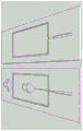
fig. 1 is a simplified depiction of a microfluidic system of the present disclosure. In the depicted system, the microfluidic system may be used to detect and/or genotype components of a biological sample. When applied to the detection of tumor cells in this particular system, a packaging device is used to package nucleated blood cells in individual droplets (left). Lysis buffer was injected into the droplets and incubated at 37 ℃ to accelerate cell lysis. A PCR mix containing primers targeting characteristic oncogenic mutations was injected into it (middle). The droplets were made to flow through a channel that meandered through a zone maintained at 65 ℃ and 95 ℃. As the droplets move through the region, their temperature cycles as required for PCR. During such a PCR reaction, if the droplet contains the genome of a tumor cell with a mutation to design a primer for detection, amplification will be initiated, producing a fluorescent output that causes the droplet to fluoresce. The droplets were then optically scanned using flow cytometry and sorted using droplet sorting to recover them (right). The droplets can be stored or used for further analysis, such as sequencing (e.g., used as input to a next generation sequencer, or provided to a sequencing facility).
Panels a-E of fig. 2 depict single cells sealed in a droplet using fluorescence assays. Yeast cells (black spots) entered from the far left and were encapsulated in the droplets, shown at low magnification (4 x objective; fig. a) and high magnification (10 x objective; fig. B). Incubating the droplets to allow the yeast to secrete its products (panel C); this produces a fluorescent compound in the droplet, so the droplet containing the high efficiency generator becomes fluorescent very quickly (panel D). The droplets were then sorted using a microfluidic sorter to extract the most efficient yeast (panel E). The scale bar represents 80 mm.
FIG. 3 depicts the use of FAM-labeled via a fluorophore Digital detection of BRAF by PCR probes, the fluorophore FAM is complementary to an amplicon derived from a portion of the human BRAF gene. Fluorescent droplets indicate amplification of the BRAF gene from purified human genomic DNA, whereas non-fluorescent droplets do not contain the gene.
Panels a-B of fig. 4 depict a binary PCR reaction for detecting CTCs. FIG. A: forward and reverse primers are encapsulated in droplets targeted to oncogenic sequences. If an oncogenic sequence is present, the PCR reaction produces a double stranded PCR product (Panel A, top), and if not, no product (Panel A, bottom). Intercalating dyes (e.g., SybrGreen) may also be present in the droplets. And B: if a double-stranded product is produced, the dye intercalates into it, becomes fluorescent, and causes the droplet to fluoresce (panel B, top); in contrast, if no double-stranded product is produced, the dye remains non-fluorescent, producing a dull droplet (panel B, bottom).
Fig. 5 is an optical microscope image of massively parallel droplet formation in a continuous bisecting device. Deionized water without cells was injected from the left. The solution flowing along the top and bottom arrows was HFE-7500 fluorocarbon oil containing 2 wt% fluorocarbon surfactant. After successive bisection, the diameter of the resulting droplet shown on the rightmost side is 25 μm.
Fig. 6 is a schematic microfluidic device and data showing a droplet-based detection procedure for CTCs. The blood cells and rare CTCs are encapsulated in microdroplets with a proteinase K-containing lysis buffer. The droplets were incubated at 55 ℃ to lyse the cells and digest the cellular proteins. The droplets were then broken up to the size optimal for imaging and proteinase K was heat inactivated. The droplets were then dermally injectable with PCR reagents and probes, then thermocycled and imaged on the Megadroplet array. Based on passing multiple
 The presence of CTC-specific transcripts detected by fluorescence of the probe identifies CTCs.
FIG. 7 shows the release of RT-PCR inhibition mediated by cell lysate by proteinase K treatment. Cells at increasing concentrations were treated with proteinase K and lysis buffer or lysis buffer alone. The cells were then incubated at 55 ℃ followed by 95 ℃. The whole cell lysate was added directly to the RT-PCR reaction in several drop-related concentrations. The strong release of PCR inhibition by the lysate was seen at a final cell concentration of 1 cell/200 pL in the proteinase K treated lysate, but not in the lysis buffer with lysate alone. PCR products were visualized on ethidium bromide stained agarose gels.
Fig. 1-3 of fig. 8 show an integrated microfluidic system (central image) for cell encapsulation/lysis, lysis and droplet splitting. FIG. 1: the co-flow module relies on laminar flow of proteinase K-containing lysis buffer and cell suspension solution to encapsulate the cells in the droplets without premature lysis or mixing of the cells prior to formation of the droplets; laminar flow boundaries are only visible between cells and the lysis buffer flow. FIG. 2: the droplet containing the cells was flowed through the 55 ℃ incubation channel for 20 minutes to lyse the cells and digest the inhibitory proteins. FIG. 3: the droplets were split to allow efficient skin injection of 2X RT-PCR reagents and imaging on the droplet array.
FIGS. 9, Panels A-C, show in a droplet after a skin injection RT-PCR. Injection of equal volumes of 2X RT-PCR reagents and EpCAM-targeting into droplets containing limiting dilutions of total RNA from the prostate cancer cell line PC3
 Probe (panel A). After picoinjection, the droplets were thermally cycled and imaged for fluorescence (panel B). The number of fluorescent droplets was found to be consistent with the prediction of poisson distribution, confirming sufficient sensitivity to detect single transcript molecules in the droplets. And (C) figure: to further confirm the results, the droplets from panel B were chemically broken and their contents run on an agarose gel to observe the presence of PCR products in the negative control droplets (-) that were not injected with RT-PCR enzyme and the experimental droplets (+) that received RT and Taq. Control reactions and picoinjection reactions performed in tubes without a skin injectability yielded bands of similar intensity, indicating comparable reaction efficiencies. White stars mark the dermal injectable droplets.
Figure 10 shows detection of EpCAM transcripts from droplet encapsulated MCF7 breast cancer cells. Using the device depicted in fig. 1-3 of fig. 8, MCF7 cells were encapsulated in droplets, the droplets were lysed and split. The lysate-containing droplets were then mesothelially injectable with RT-PCR reagents and and (3) a probe. The droplets were then thermally cycled and imaged for fluorescence. The bright field and fluorescent channel displays merge.
FIG. 11 depicts Digital droplet RT-PCR with multiplexed probes. Limiting dilutions of total RNA from Raji cells (B lymphocytes) and PC3 prostate cancer cells were mixed with RT-PCR reagents and specificity for CD45 (blue), CD44 (red) and EpCAM (green)The probes are encapsulated together in a droplet. The orange droplet indicated the presence of CD44 and EpCAM transcripts detected by the multiplex reaction. Other probe multiplexing combinations have also been seen (data not shown). The fluorescence channel is shown alone in the form of an enlarged inset of the dashed box area.
Fig. 12, panels a-C, show schematic diagrams of an apparatus for performing multiplex qPCR analysis on cells individually. The device consists of an array of approximately 1000 million traps retracted into a PDMS channel located above the thermal system (figure a). The height of the microfluidic channel is less than the diameter of the droplet, causing the droplet to adopt a flattened, flat shape. As the droplet flows through the unoccupied reduction groove, it adopts a lower, more aggressive radius of curvature, creating a force that pulls the droplet completely into the catcher (fig. B). By flowing the droplets in close-packed form, it is ensured that all the traps on the array are occupied, as shown in figure C. The entire device was thermally cycled and imaged between cycles using a microarray scanner.
Figure 13 depicts a Megadroplet array for multiplex qPCR analysis of the type depicted in figures a-C of figure 12. The droplets were aspirated and sealed in a transparent glass/epoxy chamber and fixed in place (top) using a microfabricated well array. The entire chip was clamped to a metal block and thermally cycled under a copper block using a Peltier heater. Temperature was regulated and cycled (bottom) using a thermometer, heat sink, fan (top) and digital controller. Amplification was monitored in real time by imaging the array through a transparent plate constituting the top of the device.
Panels a-B of fig. 14 depict the use of a monochromatic flow cytometer for detecting PCR amplification products in droplets via fluorescence. FIG. A: schematic of the detector consisting of a 488nm laser directed to the back of the objective lens and focused on the microfluidic channel through which the droplet flows. The laser excites the fluorescent dye within the droplet and any emitted light is captured by the objective lens and imaged on a photomultiplier tube (PMT) after it is filtered by a dichroic mirror and a 520 ± 5nm band pass filter. And B: the droplets appear as peaks of intensity over time, as shown by the output voltage of the PMT, which is proportional to the intensity of the emitted light over time for the fluorescent droplets detected.
Fig. 15, panels a-C, show schematic views of the device setup. FIG. A: the droplets, spacer oil and 1M NaCl were introduced into the PDMS device via a syringe pump. Air pressure is used to control the pump to introduce the skin injectable fluid. The electrodes from the high voltage amplifier were connected to wires immersed in the skin injectable fluid and to the metal needle of a syringe containing 1M NaCl "Faraday Mote". And B: a magnified view of the droplet spacer and the site of cutaneous injection. And (C) figure: other magnified views of the fluid uplifted skin injectable site are shown at the injection orifice.
Panels a-B of fig. 16 show bright field microscope images of the skin injectable site. In the absence of an electric field (fig. a), the surfactant prevents the injected fluid from coalescing and a distinct boundary is visible at the droplet/injected fluid interface. When an electric field is applied, the boundary disappears and the reagent is injected as the droplet passes (panel B).
Plots a-C of fig. 17 show the increase in volume fraction of droplet size (Vf) for 100mM (plot a), 50mM (plot B) and 25mM (plot C) injection fluids after injection. A stronger electric field more easily disrupts the oil/water interface, allowing injection over larger length passing droplets, and larger injection volumes. For a given voltage, a higher molar concentration of dissolved electrolyte creates a stronger electric field at the injection site, also increasing the injection volume. Error bars represent 1 standard deviation of > 1200 drops sampled at each point in either direction.
Figure 18 is a thermal map showing the variation of injection volume with applied voltage and molarity of dissolved NaCl in the injection fluid. Arrows/checkmarks indicate data points. The injection volume can be adjusted in the range of 0-36pL, with a resolution of about 2.6pL 5 (4% Vf) at 100V increments of applied signal. The maximum injection volume was 3000V with 100mM fluid. An increase in electric field above this allows electrowetting, causing spontaneous droplet formation at the pico-injector, adversely affecting injection efficacy and consistency.
FIG. 19 shows a 2% agarose gel stained with ethidium bromide. Total RNA isolated from MCF7 human cell line was encapsulated in droplets and injected into RT-PCR reaction mixtures with (+) or without 50(-) Reverse Transcriptase (RT) and Taq DNA polymerase. Non-emulsified control reactions were run in parallel. Reactions receiving only the enzyme produced the expected 100bp amplicon. Both the positive control and the cutaneous injectable reactions produced PCR products, confirming that the electric field generated during cutaneous injection was 55, biocompatible with DNA, reverse transcriptase and Taq.
Panels a-B of fig. 20 show the addition of reagents via multiple droplet coalescence. FIG. A: schematic of a microfluidic device for adding reagents via multiple droplet coalescence. The reagents to be added are introduced from the bottom together with the oil into a very small droplet maker. This results in the production of a series of very small droplets at a high frequency. The droplets to be loaded with reagents are injected from the left, separated by oil, and then the streams combine where the channels intersect the outlet of the microdroplet maker. Because the reagent droplets are much smaller than the target droplets, they are introduced at high speed frequencies, and many (tens or more) of these droplets are injected for each target droplet. Due to their small size, they flow faster than the larger droplets and collect thereafter until they reach the electrode channels they contact and can be coalesced by the electric field. And B: close-up of the coalescence region in such a microfluidic device. The droplets flow from left to right. A series of droplets is formed after the droplet to which it is to be added. Once the droplets and droplets pass through the coalescing region, the electrodes cause the droplets to coalesce into droplets. The resulting output on the right is a droplet containing the reagents present in the droplet.
Fig. 21 shows a schematic of a microfluidic device that can be used to purify droplets. That is, most of the fluid in the droplet is displaced by the purification solution without removing any discrete reagents, such as cells or beads, that may be encapsulated in the droplet. A solution is first injected into the microdroplets to dilute any impurities therein. The diluted droplets are then flowed through a microfluidic channel to which an electric field is applied using electrodes. Due to the dielectrophoretic forces generated by the electric field, cells or other discrete reagents will be displaced in the flow as they pass through the electric field. The droplet is then split so that all objects end up in one droplet. Thus, the initial droplet has been washed, as contaminants can be removed, while the presence and/or concentration of discrete reagents, such as beads or cells, that can be encapsulated within the droplet is maintained in the resulting droplet.
Panels a-B of fig. 22 show sorting. The droplet enters from the right and flows to the left, passing the electrodes. The droplets are thus sorted based on the presence (panel a; droplet flow into top output) or absence (panel B; droplet flow into bottom output) of a particular characteristic.
Fig. 23 shows a schematic of the coalescence process, starting from the formation of a double emulsion (E2) in the hydrophilic channel by re-injecting the single emulsion (E1) (top, left). These became a triple emulsion (E3) at the hydrophobic junction (bottom, left) and then coalesced using an electric field to reverse direction E2 (E2', bottom, right).
Panels a-D of fig. 24 show microscope images of (a) double emulsion (E2) formation, (b) triple emulsion (E3) formation, (c) E3 coalescence, and (D) final reverse E2 (E2') product. The scale is applicable to all images.
Fig. 25, graphs a-B, show two fast camera time series, showing E3 coalesced into E2'. The oil shell of the inner E1 is pseudo-blue.
Figures a-C of figure 26 show the microfluidic device and digital RT-PCR workflow used in the study of example 5. (A) Microfluidic tees and carrier oil were used to generate droplets containing RNA and RT-PCR reagents. Bright field microscopy images of droplet formation are shown below, the middle image shows one population of droplets generated from a single reaction mixture, and below are two populations generated from two mixtures. (B) After formation, the reverse transcriptase is injected into the droplet using a picoinjection channel triggered by an electric field applied by an electrode channel directly opposite the picoinjector. (C) The dermal injectable droplets were collected in tubes, thermally cycled, and imaged with a fluorescence microscope.
FIGS. 27, Panels A-C, show digital RT-PCR in microfluidic droplets following picoinjection of reverse transcriptase Then the determination is made. (A) Control RT-PCR reactions containing PC3 cell total RNA were emulsified on a T-junction droplet maker, thermocycled and imaged. FAM (Green) fluorescenceLight-indicating of EpCAM transcripts
 Detection and Cy5 (red) indicated detection of CD44 transcript. The bright field image (BF) of the same drop is shown on the far right side of the image. (B) RT-PCR reactions lacking reverse transcriptase were emulsified on a T-junction droplet maker and reverse transcriptase was then subcutaneously injected. On the left side of the schematic, the skin injectable fluid is depicted as dark gray. The bright field image shows that the droplet size after picoinjection approximately doubles. (C) The cutaneous injectable RT-PCR reaction subjected to omission of reverse transcriptase is not shown for EpCAM and CD44
 Word No. provesSpecificity of the assay. The red arrows indicate the direction of flow of the emulsion in the schematic.
 Scale bar 100 μm.
Panels a-B of fig. 28 show a comparison of digital RT-PCR detection rates between control droplets and dermoconjectable reverse transcriptase droplets. (A) Scatter plots of FAM and Cy5 droplet intensities for control samples (left) and picoinjection samples (right). AboutThe gating threshold for marking a drop as positive or negative is divided by a line and the scatter plot is divided into the following quadrants: (, -), (, +), (+, -), (+, +). (B) Bar graphs show CD44 and EpCAM relative to control population Normalized counts determined, mean under picoinjection
 Positive drop counts. Data represent the average of four independent experimental replicates.
FIGS. 29A-B show that the skin can be injected to enableEnabling analysis of discrete droplet populations. (A) Non-dermal injectable droplets. Control RT-PCR reactions containing mixed PC3 and Raji cell total RNA were emulsified with a T-junction droplet maker, thermocycled and imaged. Shows combined FAM and HEX fluorescence images, where FAM (green) fluorescence indicates of EpCAM transcript Detected and HEX (red) indicates the presence of PTPRC transcript. Yellow drop indication
 There is certainly a presence where the EpCAM and PTPRC transcripts are co-encapsulated in the same droplet. The bright field image (BF) is shown on the right side of the figure. (B) Injectable droplets are transdermal. The dual T-junction droplet maker produces two droplet populations that are instantly injectable transdermally at the same time. One droplet maker produced droplets containing only Raji cellular RNA, and the other droplets contained only PC3 cellular RNA. Both droplet types initially lack reverse transcriptase, which is added via a picoinjection downstream of the droplet maker. The vast majority of droplets did not show multiplexing, confirming that mass transfer during dermal injection is very rare. The red arrows indicate the direction of flow of the emulsion in the schematic.
 Scale bar 100 μm.
Panels a-B of fig. 30 show a dual transcript detection analysis indicating minimal cross-contamination during a picoinjection. (A) Scatter plots of FAM and HEX droplet intensities for co-encapsulated control samples (left) and dual population picoinjectable samples (right). Using this analysis, a large number of co-encapsulated controls were identified in the dual population of picoinjectable droplets that were virtually absent Multiple droplets (gated upper right quadrant of scatter plot). (B) Bar graphs of different bright field droplet populations relative to co-encapsulated controls and dual population skin injectable total bright field counts. Data represent the average of three experimental replicates.
Panels a-B of fig. 31 show that the dual population of RNA droplets can be stored offline and injected later. (A) An emulsion was made consisting of droplets of two populations, one containing RNA recovered from Raji cells and the other from PC3 cells. The droplets were collected in a syringe, incubated off the chip, and then reintroduced into the microfluidic device for picoinjection. The droplets are then collected, thermally cycled and imaged. These droplets are slightly more polydisperse and show higher multiplexing rates (1%) than the epithelial injectable droplets in the same device they form, most likely due to the coalescence of some droplets during incubation and re-injection. The ability to inject the emulsion to add reagents after incubation may be important for many droplet-based molecular biology assays. (B) Bright field images of the picoinjectable emulsion. Scale bar 100 μm.
Figure 32 shows an embodiment of a single cell RT-PCR microfluidic device as described herein.
Fig. 33 illustrates the effect of including a ridge structure in the channel of the microfluidic device downstream of the droplet formation junction. The left side shows a T-junction droplet maker without ridges. As the flow ratio increases, the drop maker stops forming drops, but instead forms a long jet. This is because the jets wet the channel walls and adhere, preventing droplet formation. On the right side, a similar T-shaped junction with a ridge structure is shown. The ridges trap a suitable phase, such as a hydrophobic oil phase, near the wall, making the aqueous phase difficult to wet. This allows the device to form droplets at much higher flow ratios, which then eventually wet at R ═ 0.9. This shows that the inclusion of ridges allows the droplet maker to function over a much wider range than if the ridges were omitted. The channel width is 30 microns and the peak of the ridge is about 5-10 microns. The top and bottom sets of images correspond to experiments performed with different microfluidic devices.
Fig. 34 provides a flow chart illustrating a general manufacturing flow of an embodiment of a liquid electrode as described herein.
Figure 35 provides a series of three images taken at different times than filling the electrode channels with saline (time course proceeding from left to right; figures a-C). Saline is introduced into the channel inlet and pressurized so that it slowly fills the channel. The air initially in the channel is pushed into the PDMS so eventually it is completely filled with liquid.
Fig. 36 shows electric field lines simulating various liquid electrode configurations. Simulated are positive and ground electrodes showing equipotential lines of three different geometries.
Fig. 37 provides two images of a droplet merger device that merges large droplets with small droplets using liquid electrodes. To merge the droplets, an electric field is applied using a salt-water electrode. When the electric field is off, no coalescence occurs (right) and when it is on, the droplets coalesce (left).
Fig. 38 provides two different views showing a three-dimensional schematic of a device that can be used to encapsulate a single emulsion in a double emulsion. It comprises a channel into which the single emulsion is introduced, said channel opening into a large channel into which additional aqueous phase is added. This focuses on injecting droplets through the orifice, encapsulating them in oil droplets and forming a double emulsion of water in oil.
Fig. 39 provides two schematic diagrams of PDMS plates that can be used to construct a dual emulsification device. The left plate has channels with two heights, a short channel for droplet re-injection and constriction (see previous figures) and a high channel for the aqueous phase and outlet. The right plate has only high channels. To complete the device, the plates are aligned and sealed together so that the channels are opposite. Plasma oxidation is used to bond the devices.
Fig. 40 provides a microscope image of a double emulsification device encapsulating a re-injected single emulsion into a double emulsion. The re-injected single emulsion enters from above and is enclosed in a retractor shown in the center of the device. They then exit as a double emulsion, with four shown toward the bottom of the device.
Fig. 41 provides a fluorescence microscope image of the fluorescent double emulsion. The left image shows a double emulsion formed by oscillating the fluid, which produces a large amount of polydispersity and a small number of droplets of the appropriate size for FACS sorting. The image on the right shows a double emulsion made by the microfluidic method disclosed herein, which has much greater monodispersity.
Fig. 42 provides a bar graph of the oscillating double emulsion versus the droplet region of the double emulsion produced by the device. The double emulsion produced by the device had much greater monodispersity as shown by the peaks.
Figure 43 shows FACS fluorescence and scattering data for double emulsions produced by a microfluidic device according to the present disclosure. The upper graph shows a histogram of the intensity of the population as measured with the FITC channel (about 520nm) of FACS. The lower graph shows the forward and side scatter of droplets gated according to the FITC signal.
Figure 44 shows FACS fluorescence and scattering data for the shaken double emulsion. The upper graph shows a histogram of the intensity of the population as measured with the FITC channel (about 520nm) of FACS. The lower graph shows the forward and side scatter of droplets gated according to the FITC signal.
Fig. 45 provides a histogram of droplet intensities as read with FACS (FITC channel) for four different concentrations of encapsulated dye. The dye consists of fluorescently labeled BSA.
Figure 46 shows the results of experiments designed to test the detection rate of FACS-operated droplets. Two populations of droplets were generated, one with labeled BSA fluorescence at 520nm and the other with BSA fluorescence at 647 nm. The two populations were then mixed in a defined ratio and the samples were manipulated on FACS. The measured ratios were found to be consistent with the known ratios, confirming that FACS measurements are accurate over this range.
FIG. 47 shows emulsions containing three different concentrations of DNA. All droplets containing target DNA The probe, but the target, is encapsulated in a limited concentration, so only the droplet from which the target is obtained is amplified. As the target concentration decreases, the fraction of fluorescent droplets decreases. The lower graph shows droplets after encapsulation in a double emulsion and screening using FACS.
FIG. 48 shows an emulsion containing three concentrations of DNA lower than in the previous figures. All droplets containing target DNA A probe, but the targetLimited concentration encapsulation, and therefore only the droplets from which the target is obtained will be amplified. As the target concentration decreases, the fraction of fluorescent droplets decreases. The lower graph shows droplets after encapsulation in a double emulsion and screening using FACS.
Fig. 49 shows the emulsion at the lowest DNA concentration of the three figures with respect to fig. 47 and 48. The lower graph shows droplets after encapsulation in a double emulsion and screening using FACS.
Figure 50 shows a plot of the number of positives detected by FACS analysis of double emulsions using fluorescence microscopy versus the number of positives detected by imaging the droplets prior to double emulsification. In the two groups tested (one group of ten), the results were consistent with each other.
Figure 51 provides a graph showing the fraction of positive droplets as a function of log-2 concentration. As the concentration of DNA increases, more droplets become fluorescent because more of them contain at least a single molecule.
FIG. 52 provides a diagram illustrating an Azospira process in which packaging has been used Images of droplets of PCR reactions. The top image corresponds to the reaction in which the 110bp amplicon was generated, while the bottom image corresponds to the 147bp amplicon.
FIG. 53 shows that the display corresponds to two Images of the gel of the bands of the amplicons of the PCR reaction, one was a 464bp amplicon and one was a 550bp amplicon.
Fig. 54 shows a picture of a gel validating a PCR reaction that can be multiplexed by adding multiple primer sets to a sample containing bacteria.
Fig. 55 shows the results of PCR amplification of Azospira amplicons (left) and FACS analysis of double emulsions containing Azospira (right).
Detailed description of the invention
Methods for detecting a component from a biological sample are provided. In certain aspects, the methods can be used to detect and/or quantify specific components in a biological sample, such as tumor cells (e.g., circulating tumor cells). Systems and apparatus for implementing the methods of the invention are also provided.
The subject methods and devices can be used in a wide variety of applications, such as detecting cancer, detecting aneuploidy of DNA from circulation in the maternal blood stream, monitoring disease progression, analyzing DNA or RNA content of cells, and a variety of other applications where detection and/or quantification of a particular component in a biological sample is desired.
Before the present invention is described in more detail, it is to be understood that this invention is not limited to particular embodiments described, and that it may, of course, vary. It is also to be understood that the terminology used herein is for the purpose of describing particular embodiments only, and is not intended to be limiting, since the scope of the present invention will be limited only by the appended claims.
Where a range of values is provided, it is understood that each intervening value, to the tenth of the unit of the lower limit unless the context clearly dictates otherwise, between the upper and lower limit of that range is also specifically disclosed. Each smaller range between any stated value or intervening value in a stated range and any other stated or intervening value in a stated range is encompassed within the invention. The upper and lower limits of these smaller ranges may independently be included or excluded in the range, and each range where either, neither or both limits are included in the smaller ranges is also encompassed within the invention, subject to any specifically excluded limit in the stated range. Where the stated range includes one or both of the limits, ranges excluding either or both of those included limits are also included in the invention.
Unless defined otherwise, all technical and scientific terms used herein have the same meaning as commonly understood by one of ordinary skill in the art to which this invention belongs. Although any methods and materials similar or equivalent to those described herein can be used in the practice or testing of the present invention, some potential and exemplary methods and materials may now be described. Any and all publications mentioned herein are incorporated herein by reference to disclose and describe the methods and/or materials in connection with which the publications are cited. To the extent there is a conflict, it should be understood that the present disclosure takes precedence over any disclosure of the incorporated publication.
It must be noted that, as used herein and in the appended claims, the singular forms "a," "an," and "the" include plural referents unless the context clearly dictates otherwise. Thus, for example, reference to "a droplet" includes a plurality of such droplets and reference to "the droplet" includes reference to one or more droplets, and so forth.
It is further noted that the claims may be formulated to exclude any elements that may be optional. Accordingly, such statements are intended to serve as antecedent basis for use of such exclusive terminology as "solely," "only," and the like, in connection with the recitation of claim elements, or use of a "negative" limitation.
The disclosures discussed herein are provided solely for their disclosure prior to the filing date of the present application. Nothing herein is to be construed as an admission that the invention is not entitled to antedate such disclosure by virtue of prior invention. Further, the dates of publication provided may be different from the actual publication dates which may need to be independently confirmed. To the extent that such disclosure may set forth definitions of terms that conflict with explicit or implicit definitions of the present disclosure, the definitions of the present disclosure control.
As will be apparent to those of skill in the art upon reading this disclosure, the individual embodiments described and illustrated herein each have discrete components and features which may be readily separated from or combined with the features of any of the other several embodiments without departing from the scope or spirit of the present invention. Any described methods may be performed in the order of events described, or in any other order that is logically possible.
Method of producing a composite material
As outlined above, aspects of the invention include methods for detecting a component from a biological sample. Aspects include methods of detecting, quantifying, and/or genotyping a cell, such as a normal cell (i.e., a non-tumor cell), a tumor cell, or a CTC.
As used herein, the phrase "biological sample" encompasses a variety of sample types obtained from an individual and can be used in diagnostic or monitoring assays. The definition encompasses blood and other liquid samples of biological origin, solid tissue samples such as biopsy specimens or tissue cultures or cells derived therefrom and progeny thereof. The definition also includes samples that have been treated in any way after their procurement, such as by treatment with reagents, solubilization, or enrichment for a particular component, such as a polynucleotide. The term "biological sample" encompasses clinical samples and also includes cultured cells, cell supernatants, cell lysates, cells, serum, plasma, biological fluids, and tissue samples. "biological sample" includes cells; biological fluids such as blood, cerebrospinal fluid, semen, saliva, and the like; bile; bone marrow; skin (e.g., skin biopsy); and an antibody obtained from the individual.
As described more fully herein, in various aspects, the subject methods can be used to detect various components from these biological samples. Target components include, but are not necessarily limited to, cells (e.g., circulating cells and/or circulating tumor cells), polynucleotides (e.g., DNA and/or RNA), polypeptides (e.g., peptides and/or proteins), and many other components that may be present in a biological sample.
As used herein, "polynucleotide" or "oligonucleotide" refers to a linear polymer of nucleotide monomers, and are used interchangeably. Polynucleotides and oligonucleotides can have any of a variety of structural configurations, e.g., single-stranded, double-stranded, or a combination of both, as well as higher order intramolecular or intermolecular secondary/tertiary structures, e.g., hairpins, loops, triplex regions, and the like. Polynucleotides typically range in size from a few monomeric units (e.g., 5-40 when they are commonly referred to as "oligonucleotides") to thousands of monomeric units. When a polynucleotide or oligonucleotide is represented by a series of letters (upper or lower case), such as "ATGCCTG," it is to be understood that the nucleotides are in 5 '→ 3' order from left to right, and "a" represents deoxyadenosine, "C" represents deoxycytidine, "G" represents deoxyguanosine, and "T" represents thymidine, "I" represents deoxyinosine, and "U" represents uridine, unless otherwise stated or apparent from the context. Unless otherwise indicated, the nomenclature and atom numbering conventions will follow Strachan and Read,Human Molecular Genetics 2(Wiley-Liss, New York, 1999).
The terms "polypeptide," "peptide," and "protein" are used interchangeably herein to refer to a polymeric form of amino acids of any length. NH (NH)2Refers to the free amino group present at the amino terminus of the polypeptide. COOH refers to the free carboxyl group present at the carboxyl terminus of the polypeptide. To comply with standard polypeptide nomenclature, j.biol.chem., 243(1969), 3552-3559 was used.
In certain aspects, methods are provided for enumerating and/or genotyping cells, including normal cells or tumor cells, such as CTCs. These methods are characterized by the use of microfluidics.
Fig. 1 presents a non-limiting simplified schematic of one type of microfluidic system and method of the present disclosure. A particular application depicted in fig. 1 is the detection and/or genotyping of cells (e.g., tumor cells) from biological samples. In one such method, the nucleated blood cell may be obtained from a biological sample of the subject. The nucleated blood cells were encapsulated in individual droplets using an encapsulation device (left). The droplet may then be injected with lysis buffer and incubated under conditions that accelerate cell lysis (e.g., at 37 ℃). A PCR mixture comprising one or more primers (middle) targeting a characteristic oncogenic mutation may be injected into the droplets. The droplet containing the PCR mixture can be flowed through a channel that incubates the droplet under conditions effective to perform PCR. In this figure, this is achieved by flowing the droplets through a channel that meanders through multiple zones maintained at 65 ℃ and 95 ℃. As the droplets move through the region, their temperature cycles as required for PCR. During the PCR reaction, amplification is initiated if the droplet contains the genome of the cell with the mutation for which the primer is designed for detection. The presence of these specific PCR products can be detected by, for example, fluorescence output that causes the droplets to fluoresce (FIGS. 3-4). The presence of fluorescent droplets can thus be detected, for example, by scanning the droplets using flow cytometry (fig. 14, panels a-B). In certain aspects, the droplets can also be sorted using, for example, droplet sorting to recover target droplets (right). Using the nomenclature of the present disclosure, the above steps are thus performed "under microfluidic control". That is, the steps are performed on one or more microfluidic devices.
Figures a-E of figure 2 depict a microfluidic system that includes many of the general principles and steps described above. Here, yeast cells (black spots) enter from the far left and are encapsulated in droplets, shown at low magnification (4-fold objective; FIG. A) and high magnification (10-fold objective; FIG. B). Incubating the droplets to allow the yeast to secrete its products (panel C); this produces a fluorescent compound in the droplet, so the droplet containing the high efficiency generator becomes fluorescent very quickly (panel D). The droplets were then sorted using a microfluidic sorter to extract the most efficient yeast (panel E).
Encapsulation of components from the biological sample may be achieved by any convenient method. Fig. 5 presents one possible example in which droplets are formed in a massively parallel fashion in a continuous bisecting device. For example, a cell-containing solution can be injected from the left and form large droplets that flow into a continuous bisecting array and are broken into small droplets; the droplets shown on the far right have a diameter of 25 mm. Target encapsulation methods also include, but are not limited to, hydrodynamically triggered drop formation and those described by Link et al, phys. rev. lett.92, 054503(2004), the disclosures of which are incorporated herein by reference.
As evidenced by fig. 1, 4, and 6, certain methods of the present disclosure feature the use of Polymerase Chain Reaction (PCR) -based assays to detect the presence of certain oligonucleotides and/or oncogenes present in cells. Examples of target PCR-based assays include, but are not limited to, quantitative PCR (qPCR), quantitative fluorescent PCR (QF-PCR), multiplex fluorescent PCR (MF-PCR), real-time PCR (RT-PCR), single cell PCR, PCR-RFLP/RT-PC R-RFLP, hot start PCR, nested PCR, in situ polymerase chain (in situ polony) PCR, in situ Rolling Circle Amplification (RCA), bridge PCR, picotiter PCR, and emulsion PCR. Other suitable amplification methods include Ligase Chain Reaction (LCR), transcription amplification, self-sustained sequence replication, selective amplification of a target polynucleotide sequence, consensus primer polymerase chain reaction (CP-PCR), random primer polymerase chain reaction (AP-PCR), degenerate oligonucleotide primer PCR (DOP-PCR), and nucleic acid-based sequence amplification (NABSA).
PCR-based assays can be used to detect the presence of specific genes, such as specific oncogenes. Panels a-B of fig. 4 depict PCR-based assays to detect oncogenes. In such an assay, one or more primers specific for each oncogene of interest are reacted with the genome of each cell. These primers have sequences specific for a particular oncogene, so only when they are complementary to the genome of the cell, will they hybridize and initiate PCR. If an oncogene is present and the primers match, a large number of copies of the oncogene are produced. To determine the presence or absence of an oncogene, the PCR product may be detected by the following assay: the liquid of the droplets is probed, for example by staining the solution with an intercalating dye such as SybrGreen or ethidium bromide, the PCR products are hybridized to a solid substrate such as a bead (e.g., a magnetic or fluorescent bead, such as a Luminex bead), or detected by an intermolecular reaction such as FRET. These dyes, beads, etc., are examples of "detection components," which term is used broadly and generally herein refers to any component used to detect the presence or absence of a PCR product.
A number of variations of these basic methods will now be outlined in more detail below.
Detecting rare cells (e.g., tumor cells)
Aspects of the subject methods include detecting the presence of one or more subsets of cells (e.g., tumor cells) in a biological sample. Such a flow is depicted in fig. 6. To detect tumor cells using this method, a biological sample (e.g., whole blood) can be recovered from the subject using any convenient method. The biological sample may be processed to remove components other than cells using, for example, processing steps such as centrifugation, filtration, and the like.
Each cell in the biological sample is then encapsulated in a droplet using a microfluidic device, such as that shown in fig. 5 and/or fig. 8. Using the example from fig. 5, a solution containing cells is injected from the left and formed into large droplets that flow into a continuous bisecting array and are broken into smaller droplets. Other methods of encapsulating cells into droplets are known in the art. If desired, the cells may be stained with one or more antibodies and/or probes prior to encapsulation into the droplets. As used herein, the terms "droplet," "droplet," and "microdroplet" are used interchangeably to refer to a microspheroidal containing an aqueous phase (e.g., water), typically in the range of 0.1 to 1000 μm in diameter, which can be used to encapsulate cells, DNA, enzymes, and other components. Thus, the term may be used to refer to droplets produced in, on or by a microfluidic device.
One or more lysing agents may also be added to the droplet containing the cells under conditions that can cause the cells to burst, thereby releasing their genome. The lysing agent can be added after the cells are encapsulated into the microdroplets. Any convenient cleavage agent may be used, such as proteinase K or cytotoxin. In particular embodiments, cells may be co-encapsulated in droplets with lysis buffer containing detergents such as triton x100 and/or proteinase K. Depending on the particular lysing agent used, the particular conditions that can cause the cells to burst will vary. For example, if proteinase K is incorporated as a lysing agent, the microdroplets can be heated to about 37-60 ℃ for about 20 minutes to lyse the cells and allow proteinase K to digest cellular proteins, and then they can be heated to about 95 ℃ for about 5-10 minutes to inactivate proteinase K.
In certain aspects, cell lysis may also or instead rely on techniques that do not include the addition of a lysing agent. For example, lysis to effect perforation, shearing, grinding, etc. of cells can be achieved by mechanical techniques that can employ various geometric features. Other types of mechanical disruption such as acoustic techniques may also be used. In addition, thermal energy can also be used to lyse cells. Any convenient method of achieving cell lysis may be used in the methods described herein.
For each gene to be detected, e.g. an oncogene, a primer may be introduced into the droplet. Thus, in certain aspects, primers for all oncogenes may be present in the droplet at the same time, thereby providing a multiplexed assay. The droplet is temperature cycled so that the droplet containing the cancer cells will, for example, undergo PCR. During this time, only primers corresponding to oncogenes present in the genome will induce amplification, producing many copies of these oncogenes in the droplet. Detecting the presence of these PCR products can be accomplished in a variety of ways, for example, by using FRET, staining with an intercalating dye, or attaching it to a bead. For more information on the different options for this, see the section describing variations of the described techniques. The droplets can be optically probed to detect the PCR product (fig. 14). Optical detection of droplets may include counting the number of tumor cells present in the initial population and/or allowing identification of oncogenes present in each tumor cell.
The subject methods can be used to determine whether a biological sample contains target specific cells, such as tumor cells. In certain aspects, the subject methods can include quantifying the number of target cells, e.g., tumor cells, present in a biological sample. Quantification of the number of target cells, e.g., tumor cells, present in a biological sample can be based, at least in part, on the number of microdroplets in which PCR amplification products are detected. For example, a droplet may be produced under conditions in which a majority of droplets are expected to contain zero or one cell. Those droplets that do not contain any cells may be removed using techniques described more fully herein. After performing the PCR step outlined above, the total number of droplets that contain PCR products detected can be counted to quantify the number of target cells, e.g., tumor cells, in the biological sample. In certain aspects, the method can further comprise counting the total number of droplets to determine a cell fraction or percentage of target cells, such as tumor cells, in the biological sample.
PCR
As outlined above, in practicing the methods of the invention, PCR-based assays can be used to detect the presence of certain genes of interest, such as oncogenes, present in cells. The conditions of these PCR-based assays may be varied in one or more ways.
For example, the number of PCR primers that can be added to a droplet can vary. The term "primer" may refer to more than one primer and to a naturally occurring oligonucleotide, such as in a purified restriction digest; or a synthetically produced oligonucleotide that is capable of acting as a point of initiation of synthesis along a complementary strand when placed under conditions in which synthesis of a primer extension product that is complementary to a nucleic acid strand is catalyzed. These conditions include the presence of four different deoxynucleoside triphosphates and a polymerization inducer, such as a DNA polymerase or reverse transcriptase, in a suitable buffer ("buffer" includes substituents that act as cofactors or that affect pH, ionic strength, etc.), and at a suitable temperature. For maximum amplification efficiency, the primer is preferably single-stranded.
Complementary sequences of nucleic acid sequences as used herein refer to oligonucleotides that when aligned with a nucleic acid sequence, pair the 5 'end of one sequence with the 3' end of the other sequence and are in an "antiparallel relationship". Complementarity need not be perfect; stable duplexes may contain mismatched base pairs or unmatched bases. One skilled in the art of nucleic acid technology can empirically determine duplex stability in view of a number of variables including, for example, the length of the oligonucleotide, the percent concentration of cytosine and guanine bases in the oligonucleotide, ionic strength, and the incidence of mismatched base pairs.
The number of PCR primers that can be added to the microdroplet can have the following range: about 1 to about 500 or more, for example, about 2 to 100 primers, about 2 to 10 primers, about 10 to 20 primers, about 20 to 30 primers, about 30 to 40 primers, about 40 to 50 primers, about 50 to 60 primers, about 60 to 70 primers, about 70 to 80 primers, about 80 to 90 primers, about 90 to 100 primers, about 100 to 150 primers, about 150 to 200 primers, about 200 to 250 primers, about 250 to 300 primers, about 300 to 350 primers, about 350 to 400 primers, about 400 to 450 primers, about 450 to 500 primers, or about 500 primers or more.
These primers may contain primers directed against one or more target genes, such as oncogenes. The number of primers of the target gene added may be about 1 to 500, for example, about 1 to 10 primers, about 10 to 20 primers, about 20 to 30 primers, about 30 to 40 primers, about 40 to 50 primers, about 50 to 60 primers, about 60 to 70 primers, about 70 to 80 primers, about 80 to 90 primers, about 90 to 100 primers, about 100 to 150 primers, about 150 to 200 primers, about 200 to 250 primers, about 250 to 300 primers, about 300 to 350 primers, about 350 to 400 primers, about 400 to 450 primers, about 450 to 500 primers, or about 500 primers or more. Genes of interest and oncogenes include, but are not limited to, BAX, BCL2L1, CASP8, CDK4, ELK1, ETS1, HGF, JAK2, JUNB, JUND, KIT, KITLG, MCL1, MET, MOS, MYB, NFKBIA, EGFR, Myc, EpCAM, NRAS, PIK3CA, PML, PRKCA, RAF1, RARA, REL, renl, 1, RUNX1, SRC, STAT, 3, CD45, keratin, CEA, CD133, HER2, CD44, CD49f, CD146, MUC1/2, and ZHX 2.
These primers and/or reagents may be added to the microdroplet in one step, or in more than one step. For example, the primer may be added in two or more steps, three or more steps, four or more steps, or five or more steps. Regardless of whether the primers are added in one step or more than one step, they may be added after the addition of the lysing agent, before the addition of the lysing agent, or simultaneously with the addition of the lysing agent. When added before or after the addition of the lysing agent, the PCR primers may be added in a step different from the step of adding the lysing agent.
Once the primers have been added to the microdroplet, the microdroplet may be incubated under conditions that allow PCR. The microdroplet may be incubated on the same microfluidic device as used for adding the primer, or the microdroplet may be incubated on another device. In certain embodiments, incubating the microdroplet under conditions that allow for PCR amplification is performed on the same microfluidic device as used for encapsulating and lysing cells. Incubation of the microdroplets may take a variety of forms. In certain aspects, a droplet containing a PCR mixture can be flowed through a channel that incubates the droplet under conditions effective to perform PCR. Flowing the droplets through the channel may include a channel that meanders through various temperature zones maintained at temperatures effective for performing PCR. These channels may, for example, be cycled over two or more temperature zones, wherein at least one zone is maintained at about 65 ℃ and at least one zone is maintained at about 95 ℃. As the droplets move through these regions, their temperature cycles as required for PCR. The precise number of regions and individual temperatures for each region can be readily determined by one skilled in the art to achieve the desired PCR amplification.
In other embodiments, incubation of the microdroplet may comprise using a device of the general type depicted in figures a-C and figure 13 of figure 12; this general type of device may be referred to herein as a "Megadroplet array". In such devices, an array of traps in hundreds, thousands, or millions of retracted channels (e.g., PDMS channels) are located above the thermal system (fig. 12, fig. a). The channels may be pressurized to prevent the escape of gas. The height of the microfluidic channel is less than the diameter of the droplet, causing the droplet to adopt a flattened, flat shape. As the droplet flows through the unoccupied reduction groove, it adopts a lower, more energetically favorable radius of curvature, creating a force that pulls the droplet completely into the catcher (fig. 12, fig. B). By flowing the droplets in close-packed form, it is ensured that all the traps on the array are occupied, as shown in diagram C of fig. 12. The entire device may be thermally cycled using a heater.
In certain aspects, the heater includes a peltier plate, a heat sink, and a control computer. The peltier plate allows the chip to be heated or cooled above or below room temperature by controlling the applied current. To ensure a controlled and reproducible temperature, the computer may monitor the temperature of the array using an integrated temperature probe, and may adjust the applied current as needed for heating and cooling. The metal (e.g., copper) plate allows for uniform application of heat and dissipation of excess heat during the cooling cycle, thereby enabling cooling from about 95 ℃ to about 60 ℃ in about one minute.
The method of the invention may further comprise introducing one or more probes into the droplet. As used herein with respect to nucleic acids, the term "probe" refers to a labeled oligonucleotide that forms a duplex structure with a sequence in a target nucleic acid due to the complementarity of at least one sequence in the probe with a sequence in the target region. The probe preferably does not contain a sequence complementary to the sequence used to prime the polymerase chain reaction. The number of probes that can be added can be about 1 to 500, for example, about 1 to 10 probes, about 10 to 20 probes, about 20 to 30 probes, about 30 to 40 probes, about 40 to 50 probes, about 50 to 60 probes, about 60 to 70 probes, about 70 to 80 probes, about80 to 90 probes, about 90 to 100 probes, about 100 to 150 probes, about 150 to 200 probes, about 200 to 250 probes, about 250 to 300 probes, about 300 to 350 probes, about 350 to 400 probes, about 400 to 450 probes, about 450 to 500 probes, or about 500 probes or more. The probe may be introduced into the microdroplet before, after, or after the addition of one or more primers. Target probes include (but are not limited to) Probes (e.g., as described in Holland, P.M.; Abramson, R.D.; Watson, R.; Gelfand, D.H. (1991.) the "Detection of specific polymerase chain reaction product by digestion the 5 '- - - - - -3' exonic cleavage activity of Thermus aquaticus DNA polymerase", PNAS, 88 (16): 7276. alpha. 7280).
In certain embodiments, RT-PCR based assays can be used to detect the presence of a particular transcript of interest, such as an oncogene, in a cell. In these embodiments, in addition to the reagents used to perform PCR as described herein, reverse transcriptase and any other reagents necessary for cDNA synthesis (collectively "RT-PCR reagents") are added to the microdroplets. The RT-PCR reagents are added to the microdroplet using any of the methods described herein. Once RT-PCR reagents have been added to the microdroplet, the microdroplet may be incubated under conditions that allow reverse transcription, followed by conditions that allow PCR as described herein. The microdroplets may be incubated on the same microfluidic device as used to add the RT-PCR reagents, or may be incubated on another device. In certain embodiments, incubating the microdroplet under conditions that allow RT-PCR is performed on the same microfluidic device as used to encapsulate the cells and lyse the cells.
In certain embodiments, the reagents added to the microdroplets for RT-PCR or PCR further comprise a fluorescent DNA probe capable of detecting real-time RT-PCR or PCR products. Any suitable fluorescent DNA probe may be used, including but not limited to SYBR Green, Molecular Beacons and Scorpion probes. In thatIn certain embodiments, the reagents added to the microdroplet include more than one DNA probe, e.g., two fluorescent DNA probes, three fluorescent DNA probes, or four fluorescent DNA probes. The use of multiple fluorescent DNA probes allows simultaneous measurement of RT-PCR or PCR products in a single reaction.
Duplex PCR
To amplify rare transcripts, the microdroplets that have undergone a first RT-PCR or PCR reaction as described herein may be further subjected to a second PCR reaction. In some embodiments, a portion of the droplet that has undergone the first step RT-PCR or PCR reaction is extracted from the droplet and coalesced with a droplet containing other PCR reagents, including but not limited to enzymes (e.g., DNA polymerases), DNA probes (e.g., fluorescent DNA probes), and primers. In certain embodiments, the droplet containing the additional PCR reagents is larger than the droplet that has undergone the first step RT-PCR or PCR reaction. This may be advantageous, for example, because it allows dilution of cellular components that may inhibit the second step PCR. The second PCR reaction can be performed on the same microfluidic device as used to perform the first reaction or on a different microfluidic device.
In some embodiments, the primers used in the second PCR reaction are the same primers used in the first RT-PCR or PCR reaction. In other embodiments, the primers used in the second PCR reaction are different primers than those used in the first reaction.
Multiplexing
In certain embodiments of the subject methods, multiple biomarkers can be detected and analyzed for specific cells. The detected biomarkers can include, but are not limited to, one or more proteins, transcripts, and/or genetic markers or combinations thereof in the genome of the cell. With standard fluorescence-based detection, the number of biomarkers that can be interrogated simultaneously may be limited to the number of fluorescent dyes that can be visualized independently within each droplet. In certain embodiments, the number of biomarkers that can be individually detected within a particular droplet can be increased. This may be achieved, for example, by separation of the dye from different parts of the droplet. In particular embodiments, the probe may be conjugated to a dye or probe(e.g., nucleic acid or antibody probes) bound beads (e.g. Beads) are encapsulated in the microdroplets to increase the number of biomarkers analyzed. In another embodiment, fluorescence polarization can be used to achieve a greater number of detectable signals for different biomarkers of a single cell. For example, a fluorescent dye may be attached to various probes and the droplet may be visualized under different polarization conditions. In this way, dyes of the same color can be used to provide signals to different probe targets of a single cell. The use of fixed and/or permeabilized cells (as discussed in more detail below) also allows for an increased level of multiplexing. For example, labeled antibodies can be used to target protein targets localized to cellular components while not containing labeled PCR and/or RT-PCR products within the microdroplet. This allows the same color dye to be used for the antibody and for the amplicon generated by RT-PCR.
Type of droplet
The composition and nature of the droplets may vary in practicing the methods of the present invention. For example, in certain aspects, a surfactant can be used to stabilize the microdroplets. Thus, the microdroplets may comprise a surfactant-stabilized emulsion. Any convenient surfactant that allows the desired reaction to take place in the droplets may be used. In other aspects, the microdroplets are not stabilized by surfactants or particles.
The surfactant used will depend on a variety of factors, such as the oil and water phases used in the emulsion (or other suitable immiscible phases, e.g., any suitable hydrophobic and hydrophilic phases). For example, when aqueous droplets are used in fluorocarbon oil, the surfactant may have a hydrophilic block (PEG-PPO) and a hydrophobic fluorinated block (Krytox FSH). However, if the oil is switched to a hydrocarbon oil, the surfactant will be selected, for example, so that it has a hydrophobic hydrocarbon block, such as surfactant ABIL EM 90. In selecting a surfactant, desirable characteristics that may be considered in selecting a surfactant may include one or more of the following: (1) the surfactant has a low viscosity; (2) the surfactant is immiscible with the polymer used to construct the device, and therefore it does not swell the device; (3) biocompatibility; (4) the assay reagent is insoluble in the surfactant; (5) the surfactant exhibits advantageous gas solubility because it allows gas ingress and egress; (6) the surfactant has a boiling point higher than the temperature used for PCR (e.g., 95C); (7) emulsion stability; (8) the surfactant stabilizes the droplets with the desired size; (9) the surfactant is soluble in the carrier phase and not in the droplet phase; (10) surfactants have limited fluorescence properties; and (11) the surfactant remains soluble in the carrier phase over a range of temperatures.
Other surfactants, including ionic surfactants, are also contemplated. Other additives may also be included in the oil to stabilize the droplets, including polymers that increase droplet stability at temperatures above 35 ℃.
Adding reagents to the microdroplets
In practicing the subject methods, various reagents may need to be added to the microdroplet in one or more steps (e.g., about 2, about 3, about 4, or about 5 or more steps). The method of adding the reagents to the microdroplets may be varied in a number of ways. Related methods include, but are not limited to, Ahn et al, appl.phys.lett.88, 264105 (2006); priest et al, appl. phys. lett.89, 134101 (2006); abate et al, PNAS, 11/9/2010, vol 107, 45, 19163-19166; and those described by Song et al, anal. chem., 2006, 78(14), pages 4839-4849; the disclosure of said document is incorporated herein by reference.
For example, a reagent may be added to a droplet by a method that includes combining the droplet with a second droplet that contains the reagent. The reagents contained in the second droplet may be added by any convenient method, including in particular those described herein. Such a droplet may merge with the first droplet to produce a droplet comprising the contents of the first droplet and the second droplet.
One or more agents may also or instead be added using techniques such as droplet coalescence or transdermal injection. In droplet coalescence, a target droplet (i.e., a droplet) can be made to flow alongside a droplet containing the agent to be added to the droplet. The two droplets may be flowed such that they contact each other, but not the other. These droplets may then be passed through electrodes or other means of applying an electric field that may destabilize the droplets so that they merge together.
Agents may also or instead be added using transdermal injections. In this method, a target droplet (i.e., a microdroplet) may be flowed through a channel containing a reagent to be added, wherein the reagent is under high pressure. However, due to the presence of the surfactant, in the absence of an electric field, the droplet will flow through without being injected, as the surfactant coating the droplet may prevent fluid ingress. However, if an electric field is applied to the droplet as it flows through the injector, a fluid containing the reagent will be injected into the droplet. The amount of reagent added to the droplet can be controlled by several different parameters, for example by adjusting the injection pressure and the velocity of the flowing droplet, by switching the electric field on and off, etc.
In other aspects, one or more reagents may also or instead be added to the microdroplets by methods that do not rely on merging two droplets together or injecting a liquid into the droplets. In practice, one or more reagents may be added to the microdroplet by a method comprising the steps of: emulsify the reagents into a stream of very small droplets, and combine these droplets with the target droplets (fig. 20, panels a-B). These methods will be referred to herein as "adding agent by multi-droplet coalescence". These methods make use of the fact that: since the drops to be added are small compared to the size of the target drops, the small drops will flow faster than the target drops and be collected thereafter. The collection can then be combined by, for example, applying an electric field. This method may also or instead be used to add multiple reagents to a droplet by using several co-flowing streams of small droplets of different fluids. In order to be able to efficiently merge the micro-droplets and the target droplet, it is important that the micro-droplets are smaller than the channel containing the target droplet, and that the distance between the channel injecting the target droplet and the electrode applying the electric field is sufficiently long to provide time for the micro-droplets to "catch up" with the target droplet. If this channel is too short, not all of the tiny droplets will merge with the target droplet and less reagent is added than is needed. To some extent, this can be compensated for by increasing the magnitude of the electric field, which tends to make it more difficult for the droplets to coalesce. In addition to making tiny droplets on the same microfluidic device, as shown in fig. 20, panels a-B, they may also or instead be made off-line using another microfluidic droplet maker or by homogenizing and then injecting them into the device containing the target droplets.
Thus, in certain aspects, a reagent is added to a microdroplet by a method comprising: emulsifying the reagent into a stream of droplets, wherein the droplets are smaller than the size of the droplets; flowing the droplet with a droplet; and merging the droplet with the microdroplet. The diameter of the droplets contained in the droplet stream can vary within a range of about 75% or less of the diameter of the droplets, e.g., the diameter of the flowing droplet is about 75% or less of the diameter of the droplet, about 50% or less of the diameter of the droplet, about 25% or less of the diameter of the droplet, about 15% or less of the diameter of the droplet, about 10% or less of the diameter of the droplet, about 5% or less of the diameter of the droplet, or about 2% or less of the diameter of the droplet. In certain aspects, a plurality of flowing droplets may be combined with a droplet, such as 2 or more droplets, 3 or more, 4 or more, or 5 or more. Such merging may be achieved by any convenient method, including (but not limited to) by applying an electric field, wherein the electric field is effective for merging the flowing droplet with the droplet.
As a variation of the above method, the fluid may be sprayed. That is, rather than emulsifying the fluid to be added into a flowing droplet, a long jet of such fluid may be formed and flow alongside the target droplet. The two fluids may then be combined by, for example, applying an electric field. The result is a jet with a bump where the droplet can naturally break up into droplets of the approximate size of the target droplet due to Rayleigh high instability (Rayleigh plateau instability) before merging. Many variations are contemplated. For example, one or more agents may be added to the jetting fluid to make it easier to jet, such as gelling agents and/or surfactants. Furthermore, the viscosity of the continuous fluid may also be adjusted to achieve jetting, such as described by Utada et al, phys. rev. lett.99, 094502(2007), the disclosure of which is incorporated herein by reference.
In other aspects, one or more reagents may be added using a method that uses the injection fluid itself as an electrode by utilizing an electrolyte dissolved in a solution (fig. 15-19). This general type of process is more fully described in example 3 herein.
In another aspect, the agent is added to a droplet (e.g., a microdroplet) formed at an earlier time by encapsulating the droplet to which the agent is added (i.e., the "target droplet") inside a droplet containing the agent to be added (the "target agent"). In certain embodiments, this method is performed by first encapsulating the target droplets in a shell of a suitable hydrophobic phase (e.g., oil) to form a double emulsion. The double emulsion is then encapsulated by droplets containing the agent of interest to form a triple emulsion. To combine the target droplet with a droplet containing the target agent, the double emulsion is then burst open using any suitable method, including but not limited to, applying an electric field, adding chemicals that destabilize the droplet interface, flowing the triple emulsion through shrinker and other microfluidic geometries, applying mechanical agitation or ultrasound, increasing or decreasing the temperature, or by encapsulating magnetic particles in a droplet that can break the double emulsion interface when pulled by a magnetic field. Methods of making triple emulsions and combining target droplets with target agents are described in example 4 provided herein.
Detection of PCR products
In practicing the subject methods, the manner in which PCR products can be detected can vary. For example, if the goal is to simply count the number of specific cell types, e.g., tumor cells, present in the population, this can be achieved by using a simple binary assay in which SybrGreen or any other stain and/or intercalating stain is added to each microdroplet so that the droplets will become fluorescent in the presence of a characteristic gene (e.g., oncogene) and produce PCR products. The change in fluorescence may be due to fluorescence polarization. Detecting the component can include using an intercalating stain (e.g., SybrGreen).
A variety of different detection components can be used in practicing the subject methods, including the use of fluorescent dyes known in the art. Fluorescent dyes can generally be divided into families, such as fluorescein and its derivatives; rhodamine and derivatives thereof; cyanines and derivatives thereof; coumarin and derivatives thereof; waterfall blue and its derivatives; fluorescein and its derivatives; BODIPY and its derivatives, and the like. Exemplary fluorophores include indocarbocyanine (C3), indodicarbocyanine (C5), Cy3, Cy3.5, Cy5, Cy5.5, Cy7, Texas red, Pacific blue, Oregon green 488, Alexa Fluor-355, Alexa Fluor 488, Alexa Fluor 532, Alexa Fluor 546, Alexa Fluor-555, Alexa Fluor 568, Alexa Fluor 594, Alexa Fluor 647, Alexa Fluor 660, Alexa Fluor680, JOE, lissamine, rhodamine green, BOY, Fluorescein Isothiocyanate (FITC), carboxy-Fluorescein (FAM), phycoerythrin, rhodamine, dichlororhodamine (dRhodamine), carboxytetramethylrhodamine (TAMRA), carboxy-X-rhodamine (DIPX), DIPLEX, PET, SYBOROBR, Green, and the like. Fluorophores and their use are described, inter alia, in r.haugland, Handbook of Fluorescent Probes and research Products, 9 th edition (2002), Molecular Probes, Eugene, oreg.; schena, Microarray Analysis (2003), John Wiley & Sons, Hoboken, n.j.; synthetic Medicinal Chemistry 2003/2004 catalog, Berry and Associates, Ann Arbor, Mich.; hermanson, Bioconjugate Techniques, Academic Press (1996); and Glen Research 2002 catalog, Sterling, VA.
Panels a-B of fig. 14 depict the use of a monochromatic flow cytometer that can be used, for example, to detect droplets containing tumor cells. Fig. a presents a schematic view of a detector consisting of a 488nm laser directed at the back of the objective lens and focused onto the microfluidic channel through which the droplet flows. The laser excites the fluorescent dye within the droplet and any emitted light is captured by the objective lens and imaged onto the PMT after it is filtered by the dichroic mirror and 520 ± 5nm band pass filter. Turning to fig. B, the droplets appear as peaks in intensity over time, as shown by the output voltage of the PMT, which is proportional to the intensity of the emitted light over time for the fluorescent droplets detected.
This concept is further illustrated by the diagrams a-B of fig. 3 and 4. FIG. 3, for example, depicts the use in a microdroplet being assayed PCR assay a non-limiting example of digital detection of BRAF is performed. Fluorescent droplets indicate amplification of BRAF genes from human genomic DNA, whereas non-fluorescent droplets do not contain the genes. Turning to fig. 4, panels a-B, this flow is summarized. In panel a of fig. 4, a schematic is presented showing encapsulation of forward and reverse primers in a microdroplet targeting an oncogenic sequence. If an oncogenic sequence is present, the PCR reaction produces a double stranded PCR product (Panel A, top), and if not, no product (Panel A, bottom). SybrGreen or any other type of intercalating dye is also present in the droplets. The results are depicted by the image in panel B of fig. 4, in that if a double stranded product is produced, the dye intercalates therein, becomes fluorescent, and causes the droplet to fluoresce (fig. 4, panel B, top); in contrast, if no double-stranded product is produced, the dye remains non-fluorescent, producing a dull droplet (fig. 4, panel B, bottom).
In other aspects, other tests may be required, particularly if the goal is to further characterize the oncogenes present. For example, in the case of multiplex assays described more fully herein (example 2), this can be achieved by having a light output associated with the genes amplified in the droplets. Another approach would be to use binary output, for example, with an intervening stain, to simply determine which droplets have any oncogenes. These can then be sorted to recover these droplets so that they can be analyzed in more detail to determine which oncogenes they contain. To determine the presence of oncogenes in such droplets, microfluidic or non-microfluidic techniques may be used. Using non-microfluidic techniques, droplets identified as containing oncogenes may be placed in wells on a multi-well plate where they will be diluted to a larger volume, thereby releasing all PCR products produced during the multiplex PCR reaction. The sample from this well can then be transferred to other wells, to each of which a primer for one of the oncogenes is added. These wells are then temperature cycled to initiate PCR, at which point an intercalating stain will be added to cause the wells with the matching oncogenes and primers to be illuminated.
Thus, in practicing the subject methods, components can be detected based on, for example, a change in fluorescence. In certain aspects, the change in fluorescence is due to Fluorescence Resonance Energy Transfer (FRET). In this method, a special set of primers can be used, where the 5 'primer has a quencher dye and the 3' primer has a fluorescent dye. These dyes can be disposed anywhere on the primer, at the end or in the middle. Because the primers are complementary, they will be present in solution in duplex form, and therefore the emission of the fluorescent dye will be quenched by the quenching dye, as they will be in close proximity to each other, causing the solution to appear dull. After PCR, these primers will be incorporated into the long PCR product and will therefore be far from each other. This will cause the fluorescent dye to emit light, causing the solution to become fluorescent. Thus, to detect the presence or absence of a particular oncogene, the intensity of the droplet may be measured at the wavelength of the fluorescent dye. To detect the presence of different oncogenes, this will be done with different coloured dyes for the different primers. This will cause the droplet to become fluorescent at all wavelengths of the primer corresponding to the oncogenes present in the cell.
Sorting
In practicing the methods of the present disclosure, one or more sorting steps may be employed. Related analytical methods include, but are not necessarily limited to, methods involving the use of membrane valves, branched channels, surface acoustic waves, and/or dielectrophoresis. Related sorting methods further include those depicted in FIGS. 2 and 22, panels A-B, and those described by Agresti et al, PNAS Vol.107, No. 9, 4004-; the disclosure of which is incorporated herein by reference. The population may be enriched by sorting in that a population containing a mixture of members with or without the desired property may be enriched by removing those members that do not, thereby producing an enriched population with the desired property.
Sorting may be applied before or after any of the steps described herein. Further, two or more sorting steps may be applied to a population of microdroplets, for example, about 2 or more sorting steps, about 3 or more, about 4 or more, or about 5 or more, etc. When multiple sorting steps are applied, the steps may be substantially the same or different in one or more ways (e.g., sorting based on different characteristics, sorting using different techniques, etc.).
Furthermore, the droplets may be purified before or after any sorting step. Fig. 21 presents a schematic view of a microfluidic device that can purify droplets. That is, the majority of the fluid in the droplet is replaced with the purification solution without removing any discrete reagents, such as cells or beads, that may be encapsulated in the droplet. A solution is first injected into the microdroplets to dilute any impurities therein. The diluted droplets are then flowed through a microfluidic channel on which an electric field is applied using electrodes. Due to the dielectrophoretic forces generated by the electric field, cells or other discrete reagents will be displaced in the flow as they pass through the electric field. The droplet then breaks up so that all objects end up in one droplet. Thus, the initial droplet has been purified in that contaminants can be removed while maintaining the presence and/or concentration of discrete reagents, such as beads or cells, that can be encapsulated within the droplet in the resulting droplet.
The droplets may be sorted based on one or more characteristics. Relevant properties include, but are not limited to, size, viscosity, mass, buoyancy, surface tension, electrical conductivity, charge, magnetism, and/or presence or absence of one or more components. In certain aspects, sorting may be performed based at least in part on the presence or absence of cells in the microdroplet. In certain aspects, sorting can be based at least in part on detection of the presence or absence of PCR amplification products.
Droplet sorting can be used, for example, to remove droplets in which cells are not present. Encapsulation may result in one or more droplets, including most droplets in which cells are not present. If these empty droplets are left in the system, they will be processed into any other droplets, during which time reagents and time are wasted. To achieve the highest speed and efficiency, these empty droplets can be removed by droplet sorting. For example, as described in example 1, the droplet maker can operate close to the drop-to-jet transition, such that in the absence of cells, 8 μm droplets are formed; in contrast, when cells are present, the turbulence created in the flow will trigger the disintegration of the jet, forming droplets with a diameter of 25 μm. The device can thus produce a double dispersed population of 8 μm empty droplets and 25 μm droplets containing single cells, which can then be size sorted by using, for example, a hydrodynamic sorter to recover only the larger single cell-containing droplets.
Related passive sorters include hydrodynamic sorters that sort droplets into different channels according to size based on the different manner in which small and large droplets pass through a microfluidic channel. Also relevant is a batch sorter, a simple example of which is a tube containing droplets of different masses in a gravitational field. Lighter droplets with greater buoyancy will naturally migrate to the top of the vessel by centrifuging, agitating and/or oscillating the tube. Droplets having magnetic properties can be sorted in a similar way except that by applying a magnetic field to the container, the droplets having magnetic properties will naturally migrate towards the container depending on the magnitude of those properties. A passive sorter as used in the subject method may also include relatively large channels that will simultaneously sort a large number of droplets based on the flow characteristics of the droplets.
Pierce injection may also be used to change the electrical properties of the droplets. This can be used, for example, to change the conductivity of the droplets by adding ions, which can then be used to sort the droplets, for example, using dielectrophoresis. Alternatively, a pico-injection may also be used to charge the droplets. This can be achieved by injecting a charged fluid into the droplet, so that after injection, the droplet will be charged. This will produce a collection of droplets, some of which are charged and others are not, and the charged droplets can then be extracted by flowing them through a region of an electric field that will deflect the droplets based on their charge amount. The resulting charge on the droplets can be adjusted to produce droplets with different charges by adjusting the picoinjection to inject different amounts of liquid, or by adjusting the voltage to inject different charges for a fixed injection volume. These droplets are then deflected by different amounts in the field region, thereby sorting them into different containers.
Suitable subjects
The subject methods can be applied to biological samples taken from a variety of different subjects. In many embodiments, a subject is a "mammal" or "mammal," where these terms are used broadly to describe organisms within the class mammalia, including the orders carnivore (e.g., dogs and cats), rodentia (e.g., mice, guinea pigs, and rats), and primates (e.g., humans, chimpanzees, and monkeys). In many embodiments, the subject is a human. The subject methods are applicable to human subjects of both genders and at any developmental stage (i.e., neonates, infants, juveniles, adolescents, adults), where in certain embodiments the human subject is a juvenile, adolescent, or adult. While the present invention is applicable to human subjects, it is to be understood that the subject methods can also be performed on other animal subjects (i.e., in "non-human subjects"), such as, but not limited to, birds, mice, rats, dogs, cats, livestock, and horses. Thus, it will be appreciated that any subject in need of evaluation in accordance with the present disclosure is suitable.
Furthermore, suitable subjects include subjects already diagnosed with a condition, such as cancer, and subjects not diagnosed with a condition, such as cancer. Suitable subjects include those that exhibit clinical manifestations of one or more cancers and those that do not. In certain aspects, the subject may be a subject at risk for developing cancer due to one or more factors, such as family history, chemical and/or environmental exposure, genetic mutations (e.g., BRCA1 and/or BRCA2 mutations), hormones, infectious agents, radiation exposure, lifestyle (e.g., diet and/or smoking), the presence of one or more other disease conditions, and the like.
As described more fully above, a variety of different types of biological samples may be obtained from these subjects. In certain embodiments, whole blood is drawn from the subject. If desired, whole blood may be processed prior to performing the subject methods, e.g., by centrifugation, fractionation, purification, and the like. The volume of the whole blood sample drawn from the subject can be 100mL or less, e.g., about 100mL or less, about 50mL or less, about 30mL or less, about 15mL or less, about 10mL or less, about 5mL or less, or about 1mL or less.
The subject methods and devices provided herein are compatible with both fixed and living cells. In certain embodiments, the subject methods and devices are performed with living cells. In other embodiments, the subject methods and devices are practiced with fixed cells. The fixation of the cell sample allows the extraction of small molecules and lipids from the sample to be washed that may interfere with downstream analysis. Furthermore, the fixation and infiltration of cells allows the cells to be stained with antibodies against surface proteins as well as intracellular proteins. In combination with the RT-PCR methods described herein, this staining can be used to achieve high levels of multiplexing because the antibodies are localized to the cell sample, while the microdroplets do not contain RT-PCR products. Such a configuration allows the same color dye to be used for the antibody and for the amplicon produced by RT-PCR. Any suitable method may be used to fix the cells, including (but not limited to) fixation using formaldehyde, methanol, and/or acetone.
RT-PCR of the immobilized cells encapsulated in the microdroplets can be performed by first diluting the microdroplet and performing an RT-PCR reaction on the diluted microdroplet sample. This dilution of the cell sample can help to limit any cellular compounds that would interfere with RT-PCR. In other embodiments, the RT-PCR reagents are added directly to the microdroplets containing the immobilized cells in a "one-pot" reaction in the absence of any dilution of the sample. In certain embodiments, the immobilized cells are solubilized prior to RT-PCR using a protease and a detergent.
Genotyping of cells
As outlined above, aspects of the invention also include methods of genotyping a component from a biological sample. "genotyping" means the detection of two or more oligonucleotides (e.g., oncogenes) in a particular cell. Aspects include methods of genotyping cells, such as tumor cells (including CTCs).
In certain such aspects, the method comprises encapsulating cells of a blood sample obtained from a subject in a droplet, wherein one cell is present in the droplet; introducing a lysing agent into the microdroplet and incubating the microdroplet under conditions effective to lyse the cells; introducing Polymerase Chain Reaction (PCR) reagents and a plurality of PCR primers into the microdroplet and incubating the microdroplet under conditions that allow for PCR amplification to produce PCR amplification products, wherein the plurality of PCR primers comprises one or more primers that each hybridize to one or more oncogenes; introducing a plurality of probes into the microdroplet, wherein the probes hybridize to one or more target mutations and fluoresce at different wavelengths; and detecting the presence or absence of a particular PCR amplification product by detection of probe fluorescence, wherein detection of fluorescence indicates the presence of the PCR amplification product; wherein one or more steps are performed under microfluidic control.
In other aspects, the method can include encapsulating cells of a blood sample obtained from a subject in a droplet, wherein one cell is present in the droplet; introducing a lysing agent into the microdroplet and incubating the microdroplet under conditions effective to lyse the cells; introducing Polymerase Chain Reaction (PCR) reagents and a plurality of PCR primers into the microdroplet and incubating the microdroplet under conditions that allow for PCR amplification to produce PCR amplification products, wherein the plurality of PCR primers comprises one or more primers that each hybridize to one or more oncogenes, the primers comprising a forward primer comprising a label, and a reverse primer comprising a capture sequence; introducing fluorescent beads into the microdroplet, wherein the beads comprise a nucleotide sequence complementary to a capture sequence; and detecting the presence or absence of the PCR amplification product by detection of fluorescence of the bead and primer fluorescence, wherein detection of fluorescence indicates the presence of the PCR amplification product; wherein one or more steps are performed under microfluidic control.
In carrying out the method for genotyping cells, any variation may be made in the general steps described herein, e.g., the number of primers that may be added, the manner in which the reagents are added, the appropriate subject, etc.
Detecting cancer
The method according to the invention also comprises a method for detecting cancer. These methods may include encapsulating oligonucleotides of a biological sample obtained from a subject in a droplet, wherein at least one oligonucleotide is present in the droplet; introducing Polymerase Chain Reaction (PCR) reagents, a detection component, and a plurality of PCR primers into the microdroplet and incubating the microdroplet under conditions that allow for PCR amplification to produce PCR amplification products, wherein the plurality of PCR primers comprises one or more primers that each hybridize to one or more oncogenes; and detecting the presence or absence of the PCR amplification product by detection of the detection component, wherein detection of the detection component indicates the presence of the PCR amplification product.
Detection of one or more PCR amplification products corresponding to one or more oncogenes may indicate that the subject has cancer. The specific oncogene added to the microdroplet may be altered. In certain aspects, the oncogenes may be specific for a particular type of cancer, such as breast cancer, colon cancer, and the like.
In addition, the biological sample in which components are to be detected may vary in the practice of the subject methods, and may be based at least in part on the particular type of cancer sought to be detected. For example, in certain instances, breast tissue can be used as a biological sample if it is desired to determine whether a subject has breast cancer or the like.
In practicing the methods for detecting cancer, any variation can be made in the general steps described herein, e.g., the number of primers that can be added, the manner in which the reagents are added, the appropriate subject, etc.
Device for measuring the position of a moving object
As indicated above, embodiments of the present invention use microfluidic devices. The microfluidic devices of the present invention can be characterized in a variety of ways. In certain embodiments, for example, a microfluidic device has at least one "micro" channel. The channels can have at least one cross-sectional dimension on the order of millimeters or less (e.g., less than or equal to about 1 millimeter). Obviously, for some applications, this size may be adjusted; in some embodiments, at least one cross-sectional dimension is about 500 microns or less. In some embodiments, further, the cross-sectional dimension is about 100 microns or less (or even about 10 microns or less-sometimes even about 1 micron or less) as the application allows. The cross-sectional dimension is a dimension generally perpendicular to the direction of flow of the centerline, but it should be understood that the cross-sectional dimension used need not be strictly perpendicular to the flow when flowing through an elbow or other feature that tends to change the direction of flow. It will also be appreciated that in some embodiments, a microchannel may have two or more cross-sectional dimensions, such as the height and width of a rectangular cross-section or the major and minor axes of an elliptical cross-section. Any of these dimensions may be compared for the dimensions presented this time. It is noted that the microchannels used in the present invention may have two dimensions that differ widely-for example, a rectangular cross-section having a height of about 100 and 200 microns and a width on the order of centimeters or more. Of course, certain devices may employ channels in which two or more axes are very similar or even identical in size (e.g., channels having a square or circular cross-section).
In some embodiments, the microfluidic devices of the present invention are fabricated using microfabrication techniques. Such techniques are commonly used to fabricate Integrated Circuits (ICs), microelectromechanical devices (MEMS), display devices, and the like. Among the types of microfabrication processes that can be used to fabricate small-sized patterns in microfluidic devices, fabrication is photolithography (including X-ray lithography, electron beam lithography, etc.), self-aligned deposition and etching techniques, anisotropic deposition and etching processes, self-assembled mask formation (e.g., formation of a layer of a hydrophobic-hydrophilic copolymer), and the like.
In view of the foregoing, it should be appreciated that some of the principles and design features described herein may be scaled up to larger devices and systems, including devices and systems employing channels up to millimeter or even centimeter scale channel cross-sections. Thus, while some devices and systems are described as "microfluidic," it is contemplated that in certain embodiments, the description is equally applicable to some larger scale devices.
When referring to a microfluidic "device," it is generally intended to mean a single entity in which one or more channels, reservoirs, platforms, etc., share a continuous substrate, which may or may not be monolithic. A microfluidic "system" may include one or more microfluidic devices and associated fluidic connections, electrical connections, control/logic features, and the like. Aspects of microfluidic devices include the presence of one or more fluid flow paths (e.g., channels) having dimensions as discussed herein.
In certain embodiments, the microfluidic devices of the present invention provide continuous flow of a fluidic medium. Fluids flowing through channels in microfluidic devices exhibit a number of interesting properties. Generally, the dimensionless reynolds number (dimensionless reynolds number) is very low, resulting in the flow remaining laminar at all times. Furthermore, in this way, the two combined fluids will not mix easily and only diffusion can drive the mixing of the two compounds.
Various features and examples of microfluidic device components suitable for use with the present invention will now be described.
Substrate
Substrates used in microfluidic systems are supports for the necessary elements to provide fluid transport. The basic structure may be monolithic, layered or partitioned. Typically, the substrate comprises one or more microchannels (if necessary) which serve as conduits for the library of molecules and reagents. They may also include input ports, output ports, and/or features to assist in flow control.
In certain embodiments, the substrate selection may depend on the application and design of the device. The substrate materials are generally selected for their compatibility with a variety of operating conditions. Limitations on a given material in a microfabrication process are also relevant considerations in selecting an appropriate substrate. Useful substrate materials include, for example, glass, polymers, silicon, metals, and ceramics.
Polymers are standard materials for microfluidic devices because they are suitable for cost-effective and high volume production. Polymers can be classified into three categories according to their molding behavior: thermoplastic polymers, elastomeric polymers, and rigid plastic polymers. Thermoplastic polymers can be molded above the glass transition temperature and will retain these shapes after cooling below the glass transition temperature. Elastomeric polymers may be stretched upon application of an external force, but will return to the original state upon removal of the external force. The elastomer does not melt until it reaches its decomposition temperature. The hard plastic polymers must be cast into their final shape because they soften a small amount before the temperature reaches their decomposition temperature.
Among the polymers that may be used in the microfabricated device of the present invention are Polyamide (PA), polybutylene terephthalate (PBT), Polycarbonate (PC), Polyethylene (PE), polymethyl methacrylate (PMMA), Polyoxymethylene (POM), polypropylene (PP), polyphenylene ether (PPE), Polystyrene (PS), and Polysulfone (PSU). The chemical and physical properties of polymers can limit their use in microfluidic devices. In particular, lower chemical resistance, aging, mechanical stability and UV stability compared to glass can limit the use of the polymer for specific applications.
Glasses that can also be used as substrate materials have particular advantages under certain operating conditions. Since glass is chemically inert to most liquids and gases, it is particularly suitable for applications that employ specific solvents that have a tendency to dissolve plastics. In addition, its transparent nature makes the glass particularly suitable for optical or UV detection.
Surface treatment and coating
Surface modifications can be useful for controlling the functional mechanisms (e.g., flow control) of a microfluidic device. For example, it may be advantageous to keep fluid substances from adsorbing to the channel walls or to attach antibodies to the detection surface of the biological component.
Polymeric devices in particular tend to be hydrophobic, and thus loading of channels can be difficult. The hydrophobic nature of the polymer surface also makes it difficult to control electroosmotic flow (EOF). One technique for coating polymer surfaces is to apply a polyelectrolyte multilayer (PEM) to the channel surfaces. The PEM includes a continuous filling of the channels with alternating solutions of positive and negative polyelectrolytes, allowing the layers to form an electrostatic bond. Although the layers do not generally adhere to the channel surfaces, they may completely cover the channel even after long-term storage. Another technique for applying a hydrophilic layer on a polymer surface involves UV grafting of the polymer to the surface of the channels. First grafting sites, free radicals, are generated at the surface by exposing the surface to UV radiation while simultaneously exposing the device to a monomer solution. The monomers react to form a polymer covalently bonded at the reaction site.
Glass channels generally have high surface charge levels, allowing proteins to adsorb and possibly hinder the separation process. In some cases, it may be advantageous to coat the glass channels with Polydimethylsiloxane (PDMS) and/or surfactant coatings. Other polymers that may be used to prevent surface adsorption include polyacrylamides, ethylene glycol groups, polysiloxanes, glyceryl glycidoxypropyl, poly (ethylene glycol), and hydroxyethylated poly (ethylene imine). Furthermore, for electroosmotic devices it is advantageous to have a coating with an electrical charge, which can be adjusted in magnitude by manipulating the conditions (e.g. pH) inside the device. The flow direction may also be selected based on the coating, as the coating may be positively or negatively charged.
Specialized coatings may also be applied to immobilize certain species on the channel surfaces-this process is known to those skilled in the art as "functionalizing the surface". For example, a Polymethylmethacrylate (PMMA) surface can be coated with an amine to facilitate attachment of various functional groups or targets. Alternatively, the PMMA surface may be made hydrophilic by an oxygen plasma treatment process.
Microfluidic element
Microfluidic systems may contain a plurality of microchannels, valves, pumps, reactors, mixers, and other components. Some of these components and their general structure and dimensions are discussed below.
Various types of valves may be used for flow control in the microfluidic devices of the present invention. These include, but are not limited to, passive valves and check valves (membranes, flaps, bivalves, leaks, etc.). The flow rate through these valves depends on various physical characteristics of the valve, such as surface area, size of flow channels, valve material, etc. The valves also have associated operational and manufacturing advantages/disadvantages that should be taken into account during the design of the microfluidic device.
Like other microfluidic components, micropumps are subject to manufacturing limitations. Typical considerations in pump design include the handling of air bubbles, clogging, and durability. Currently available micropumps include, but are not limited to, electrically equivalent pumps, fixed stroke micro-displacement, peristaltic micro-membranes, and pumps with integrated check valves.
Large devices rely on turbulent forces, such as shaking and stirring, to mix the reagents. In contrast, these turbulent forces are not practically available in microdevices, where mixing is generally achieved by diffusion. Microstructures are typically designed to enhance the mixing process, since mixing by diffusion can be slow and inefficient. These structures manipulate the fluid in a manner that increases the interfacial surface area between the fluid regions, thereby accelerating diffusion. In certain embodiments, a microfluidic mixer is used. Such mixers can be provided upstream of (and in some cases integrated with) the microfluidic separation devices of the present invention.
Micromixers can be divided into two general categories: active mixers and passive mixers. Active mixers function by applying active control over the flow area (e.g., changing pressure gradients, charge, etc.). Passive mixers require no input of energy and use only "fluid dynamics" (e.g., pressure) to drive fluid flow at a constant rate. One example of a passive mixer involves stacking two flow streams separated by plates on top of each other. Once the separator plates are removed, the flow streams contact each other. The stacking of the two liquids increases the contact area and reduces the diffusion length, thereby enhancing the diffusion process. If thermal management is required, the mixing and reaction device may be connected to a heat transfer system. As with the larger heat exchangers, the micro heat exchangers may have co-flow, counter-flow, or cross-flow schemes. Microfluidic devices typically have channel widths and depths between about 10 μm and about 10 cm. Common channel structures include a long main separation channel, and three shorter "side branch" side channels that terminate in a buffer, sample, or waste reservoir. The separation channel may be a few centimeters long and the length of the three side channels is typically only a few millimeters. Of course, the actual length, cross-sectional area, shape, and branching design of the microfluidic device depends on the application and other design considerations, such as throughput (which depends on flow resistance), velocity profile, residence time, and the like.
The microfluidic devices described herein may include an electric field generator to perform certain steps of the methods described herein, including (but not limited to) pico injection, droplet coalescence, selective droplet fusion, and droplet sorting. In certain embodiments, the electric field is generated using metal electrodes. In a particular embodiment, the electric field is generated using liquid electrodes. In certain embodiments, the liquid electrode comprises a liquid electrode channel filled with a conductive liquid (e.g., saline or buffer) and located at a location in the microfluidic device where an electric field is desired. In certain embodiments, the liquid electrode is energized using a power supply or a high voltage amplifier. In some embodiments, the liquid electrode channel includes an inlet port such that a conductive liquid can be added to the liquid electrode channel. Such a conductive liquid may be added to the liquid electrode channel, for example, by connecting a tube filled with liquid to the inlet port and applying pressure. In certain embodiments, the liquid electrode channel further comprises an outlet port for releasing the electrically conductive liquid from the channel. In particular embodiments, liquid electrodes are used in the picoinjection, droplet coalescence, selective droplet fusion, and/or droplet sorting aspects of the microfluidic devices described herein. Liquid electrodes can be used, for example, to uncharged substances that are injected via application of an electric field.
Liquid electrodes as described herein also have applicability outside of the particular microfluidic device applications discussed herein. For example, liquid electrodes may be used in a variety of devices that typically use metal electrodes. In addition, liquid electrodes may be particularly well suited for use in flexible devices, such as devices designed to be worn on the body and/or devices that must bend due to their operation.
In certain embodiments, one or more walls of the microfluidic device channel immediately downstream of the junction with one or more of the input microchannel, the companion microchannel, and/or the picoinjection microchannel comprise one or more ridges. These ridges in the walls of the microchannel are configured to trap a layer of a suitable phase, e.g., a suitable hydrophobic phase (e.g., oil) and thereby prevent immiscible phases (e.g., aqueous phases) from contacting the walls of the microchannel, which can cause wetting of the channel walls. Such wetting may be undesirable as it may lead to unpredictable behaviorThe droplets form and/or allow fluid to be transferred between the droplets, thereby causing contamination. In certain embodiments, the ridges allow for a higher flow ratio R (Q)Aqueous phase/QSum of) And droplets are formed.
In certain embodiments, the width of one or more of the microchannels (e.g., input microchannels, paired microchannels, pico-injection microchannels, and/or flow channels upstream or downstream of one or more of these channels) of a microfluidic device is 100 microns or less, e.g., 90 microns or less, 80 microns or less, 70 microns or less, 60 microns or less, 50 microns or less, for example, 45 microns or less, 40 microns or less, 39 microns or less, 38 microns or less, 37 microns or less, 36 microns or less, 35 microns or less, 34 microns or less, 33 microns or less, 32 microns or less, 31 microns or less, 30 microns or less, 29 microns or less, 28 microns or less, 27 microns or less, 26 microns or less, 25 microns or less, 20 microns or less, 15 microns or less, or 10 microns or less. In some embodiments, one or more of the microchannels above has a width of about 10 microns to about 15 microns, about 15 microns to about 20 microns, about 20 microns to about 25 microns, about 25 microns to about 30 microns, about 30 microns to about 35 microns, about 35 microns to about 40 microns, about 40 microns to about 45 microns, or about 45 microns to about 50 microns, about 50 microns to about 60 microns, about 60 microns to about 70 microns, about 70 microns to about 80 microns, about 80 microns to about 90 microns, or about 90 microns to about 100 microns.
In certain embodiments, the base of each of the one or more ridges is from about 10 microns to about 20 microns in length, for example, from about 11 to about 19 microns in length, from about 12 to about 18 microns in length, from about 13 to about 17 microns in length, from about 14 to about 16 microns in length, or about 15 microns in length.
In certain embodiments, the peaks of each of the one or more ridges have a width of about 1 to about 10 microns, such as about 1 to about 9 microns, about 2 to about 8 microns, about 3 to about 7 microns, about 4 to about 6 microns, or about 5 microns. In certain embodiments, the peaks of each of the one or more ridges have a width of from about 1 micron to about 2 microns, from about 2 microns to about 3 microns, from about 3 microns to about 4 microns, from about 4 microns to about 5 microns, from about 5 microns to about 6 microns, from about 6 microns to about 7 microns, from about 7 microns to about 8 microns, from about 8 microns to about 9 microns, or from about 9 microns to about 10 microns.
In certain embodiments, the height of each of the one or more ridges is from about 5 microns to about 15 microns, e.g., from about 6 microns to about 14 microns, from about 7 microns to about 13 microns, from about 8 microns to about 12 microns, from about 9 microns to about 11 microns, or about 10 microns.
In certain embodiments, the ratio of the base of each of the one or more ridges to the height of each of the one or more ridges is from about 1.0: 0.75 to about 0.75: 1.0. In certain embodiments, the ratio of the base of each of the one or more ridges to the peak width of each of the one or more ridges is from about 1.0: 0.5 to about 1.0: 0.1, e.g., about 1.0: 0.2, about 1.0: 0.3, or about 1.0: 0.4.
In certain embodiments, the ratio of the base of each of the one or more ridges to the height of each of the one or more ridges to the peak width of each of the one or more ridges is about 1: 0.75: 0.5.
In certain embodiments, a channel as described herein has a plurality of ridges that extend a distance along the channel wall. This distance may be, for example, about 50 microns to about 500 microns, e.g., about 50 microns to about 450 microns, about 100 microns to about 400 microns, about 150 microns to about 350 microns, about 200 microns to about 300 microns, or about 250 microns. In certain embodiments, a plurality of ridges can be provided that extend along the channel walls for a distance, wherein the ratio between the distance along the channel walls and the channel width is from about 10: 1 to about 1: 2, e.g., about 10: 1, about 9: 1, about 8: 1, about 7: 1, about 6: 1, about 5: 1, about 4: 1, about 3: 1, about 2: 1, about 1: 1, or about 1: 2.
It should be noted that one or more of the various dimensions discussed above may be scaled up or down as appropriate for a particular application, e.g., each of the above dimensions may be scaled up or down by a factor of 2, 5, 10, or more, as appropriate.
In some embodiments, one or more channel junctions, e.g., one or more droplet-forming junctions, e.g., pico-syringe junctions, comprise a "step-down" structure. This is depicted, for example, in fig. 26, where the portion of the flow channel at the hypodermic junction and downstream of the hypodermic junction is wider than the portion of the flow channel upstream of the hypodermic junction. This step-down structure promotes the pinching off of the droplet and thus the droplet formation. The step size may be selected based on the desired size of the droplet to be formed, with larger step sizes producing larger droplets. Such a configuration may also help to avoid dripping of the substance from the hypodermic syringe after injection from the hypodermic syringe into the droplet. In some embodiments, the width of the flow channel at and downstream of the picoinjector junction is from about 5% to about 50% wider than the width of the flow channel immediately upstream of the picoinjector junction, e.g., from about 5 to about 10% wider, from about 10 to about 20% wider, from about 20 to about 30% wider, from about 30 to about 40% wider, or from about 40 to about 50% wider.
Manufacturing method
Microfabrication processes vary depending on the type of material used in the substrate and the desired throughput. For small volume production or prototypes, manufacturing techniques include LIGA, powder blasting, laser ablation, machining, electrical discharge machining, photo-forming, and the like. Techniques for mass production of microfluidic devices may use photolithography or master-based replication methods. Photolithographic processes for fabricating substrates from silicon/glass include wet and dry etching techniques commonly used to fabricate semiconductor devices. Injection molding and hot embossing are commonly used for the mass production of plastic substrates.
Glass, silicon and other "hard" materials (lithography, etching, deposition)
Microchannels and microcavities made of glass, silicon and other "hard" materials can be fabricated using a combination of photolithography, etching and deposition techniques. Techniques based on the above-described techniques are typically applied to fabricate devices on the scale of 0.1-500 microns.
Microfabrication techniques based on existing semiconductor manufacturing processes are generally performed in clean rooms. The quality of the clean room is classified by the number of particles with a size of < 4 μm per cubic inch. A typical clean room class for MEMS microfabrication is 1000 to 10000.
In certain embodiments, photolithography may be used in microfabrication. In photolithography, a photoresist that has been deposited on a substrate is exposed to a light source through a photomask. Conventional photoresist processes allow for a structure height of up to 10-40 μm. If a higher structure is desired, a thicker photoresist such as SU-8 or polyimide can be used, which results in a height of up to 1 mm.
After the pattern on the mask is transferred to the substrate covered by the photoresist, the substrate is then etched using a wet or dry process. In wet etching, the substrate-region protected by the mask is subjected to chemical attack in the liquid phase. The liquid reagent used in the etching process depends on whether the etching is isotropic or anisotropic. Isotropic etching typically uses acids to form three-dimensional structures such as spherical cavities in glass or silicon. Anisotropic etching uses highly alkaline solvents to form planar surfaces such as holes and trenches. Wet anisotropic etching on silicon produces a sloped channel profile.
Dry etching involves attacking the substrate with ions in the gas or plasma phase. Dry etching techniques can be used to create rectangular channel cross-sections and arbitrary channel paths. The various types of dry etching that may be employed include physical etching, chemical etching, physical-chemical etching (e.g., RIE), and physical-chemical etching with inhibitors. Physical etching uses ions accelerated by an electric field to bombard the surface of a substrate to "etch" a structure. Chemical etching may employ an electric field to cause chemical species to migrate to the surface of the substrate. The chemical species is then reacted with the surface of the substrate to create voids and volatile species.
In certain embodiments, deposition is used in microfabrication. Deposition techniques can be used to create layers of metals, insulators, semiconductors, polymers, proteins, and other organic substances. Most deposition techniques fall into one of two main categories: physical Vapor Deposition (PVD) and Chemical Vapor Deposition (CVD). In one method of PVD, a substrate target is contacted with a holding gas (which may be generated, for example, by evaporation). Some substances in the gas adsorb to the surface of the target, forming a layer constituting the deposit. In another method commonly used in the microelectronics manufacturing industry, a target containing the substance to be deposited is sputtered using an argon ion beam or other suitable energy source. The sputtered substance is then deposited on a surface of the microfluidic device. In CVD, a substance in contact with the target reacts with the surface to form a component that chemically bonds with the object. Other deposition techniques include: spin coating, plasma spraying, plasma polymerization, dip coating, casting, and Langmuir-Blodgett film deposition. In plasma spraying, a fine powder containing particles having a diameter of at most 100 μm is suspended in a carrier gas. The mixture containing the particles is accelerated and heated by the plasma jet. The molten particles splash onto the substrate and solidify to form a dense coating. Plasma polymerization produces a polymer film (e.g., PMMA) from a plasma containing an organic vapor.
Once microchannels, microcavities, and other features have been etched in a glass or silicon substrate, the etched features are typically sealed to ensure that the microfluidic device is "water-tight". When sealing, adhesion may be applied on all surfaces that are in contact with each other. The sealing process may involve fusion techniques, such as those developed with respect to bonding between glass-silicon, glass-glass or silicon-silicon.
Anodic bonding may be used to bond the glass to the silicon. A voltage is applied between the glass and the silicon and the temperature of the system is raised to induce sealing of the surface. The electric field and high temperature induce the sodium ions in the glass to migrate to the glass-silicon interface. Sodium ions in the glass-silicon interface are highly reactive with the silicon surface, forming solid chemical bonds between the surfaces. The type of glass used should ideally have a coefficient of thermal expansion close to that of silicon (e.g., Pyrex Coming 7740).
Fusion bonding can be used for glass-glass or silicon-silicon sealing. The substrates are first forced and aligned together by applying a high contact force. Once in contact, the substrates are held together by atomic attraction forces (primarily van der waals forces) so they can be placed in an oven and annealed at high temperatures. Depending on the material, the temperature range used is about 600 to 1100 ℃.
Polymer/plastic
According to embodiments of the present invention, a variety of techniques may be used to micromachine plastic substrates. Including laser ablation, stereolithography, oxygen plasma etching, particle jet ablation, and microelectric erosion. Some of these techniques can also be used to shape other materials (glass, silicon, ceramic, etc.).
To make multiple copies of a microfluidic device, replication techniques are used. These techniques involve first making a master or mold insert containing the pattern to be replicated. The master is then used to mass produce polymeric substrates through a polymer replication process.
In the replication process, the master pattern contained in the mold is replicated on the polymer structure. In certain embodiments, the mixture of polymer and curing agent is poured onto the mold at elevated temperature. After the mixture is cooled, the polymer contains the pattern of the mold, which is then removed from the mold. Alternatively, plastic may be injected into the structure containing the mold insert. In micro-injection, plastic heated to a liquid state is injected into a mold. After separation and cooling, the plastic retains the shape of the mold.
PDMS (polydimethylsiloxane), a silicon-based organic polymer, may be used in a molding process to form microfluidic structures. PDMS is well suited for microchannels of about 5 to 500 μm due to its elastic properties. The specific properties of PDMS make it particularly suitable for microfluidic purposes:
1) it is optically transparent, which allows visualization of the flow;
2) PDMS has elastomeric properties that facilitate keeping the microfluidic connection "water-tight" when mixed with an appropriate amount of a reticulating agent;
3) PDMS can be used to make valves and pumps using membranes due to its elasticity;
4) untreated PDMS is hydrophobic and becomes temporarily hydrophilic after oxidation of the surface by oxygen plasma or after immersion in strong alkali; oxidized PDMS adheres itself to glass, silicon, or polyethylene, as long as these surfaces themselves are exposed to oxygen plasma;
5) PDMS is permeable to gases. Filling the channel with liquid is facilitated even when there are bubbles in the channel, as the bubbles are forced out of the material. But it may also be permeable to non-polar organic solvents.
Microinjection can be used to form plastic substrates for use in a wide variety of microfluidic designs. In this process, a liquid plastic mass is first injected into a mold under vacuum and pressure at a temperature above the glass transition temperature of the plastic. The plastic is then cooled to below the glass transition temperature. After removal of the mold, the resulting plastic structure is the negative of the mold pattern.
Another replication technique is hot embossing, where the polymer substrate and master are heated to above the glass transition temperature Tg of the polymer (which is about 100-. The imprint master is then pressed against the substrate with a preset compressive force. The system is then cooled below Tg and the mold and substrate are then separated.
Generally, the polymer is subjected to the highest physical forces when separated from the mold tool, especially when the microstructure contains high aspect ratios and vertical walls. To avoid damage to the polymer microstructure, the material properties of the substrate and the mold tool may be considered. These characteristics include: sidewall roughness, sidewall angle, chemical interface between the imprint master and the substrate, and temperature coefficient. The high sidewall roughness of the imprint tool can damage the polymer microstructure because the roughness contributes to the friction between the tool and the structure during separation. If the frictional force is greater than the local tensile strength of the polymer, the microstructure may be destroyed. Friction between the tool and the substrate can be important in microstructures having vertical walls. The chemical interface between the master and the substrate may also be of interest. Because the imprinting process subjects the system to high temperatures, chemical bonds can form in the master-substrate interface. These interface bonds may interfere with the separation process. The difference in the thermal expansion coefficients of the tool and the substrate may create additional frictional forces.
Various techniques can be used to form molds, imprint masters, and other masters containing patterns for replicating plastic structures by the replication process described above. Examples of such techniques include LIGA (described below), ablation techniques, and various other machining techniques. Similar techniques can also be used for small-lot production of masks, prototypes and microfluidic structures. Materials for the die tool include metals, metal alloys, silicon, and other hard materials.
Laser ablation can be used to form microstructures directly on a substrate or through the use of a mask. This technique uses a precisely directed laser, typically having a wavelength between infrared and ultraviolet. Laser ablation can be performed on glass and metal substrates as well as on polymer substrates. Laser ablation can be performed by moving the substrate surface relative to a stationary laser beam or by moving the laser beam relative to a stationary substrate. Various pores, channels and high aspect structures can be fabricated using laser ablation.
Certain materials, such as stainless steel, make very durable mold inserts and can be micro-machined to form structures as small as the 10 μm range. Various other micromachining techniques for microfabrication exist, including μ electrical discharge machining (μ -EDM), μmilling, focused ion beam milling. mu-EDM allows the fabrication of 3-dimensional structures in electrically conductive materials. In μ -EDM, material is removed by generating a high frequency discharge between an electrode (cathode tool) and a workpiece (anode). Both the workpiece and the tool are immersed in a dielectric fluid. This technique produces a rougher surface but provides flexibility in material and geometry.
Electroplating can be used to make replica mold tools/masters made of, for example, nickel alloys. The method starts with a lithography step in which a photoresist is used for the defined plated structures. The areas to be plated do not contain resist. For structures with high aspect ratios and low roughness requirements, LIGA may be used to create the plated forms. LIGA is a german abbreviation for Lithographic (photolithography), galvanoforming, abenforming. In one approach to LIGA, a thick PMMA layer is exposed to x-rays from a synchrotron source. The surface produced by LIGA has low roughness (about 10nm RMS) and the resulting nickel tool has good surface chemistry for most polymers.
With respect to glass and silicon devices, polymer microfluidic devices must be enclosed before they become functional. Common problems in the bonding process of microfluidic devices include clogging of the channels and changes in the physical parameters of the channels. Lamination is one method used to seal plastic microfluidic devices. In one lamination process, a PET foil (about 30 μm) coated with a molten adhesive layer (typically 5-10 μm) is roll coated onto the microstructures with a heated roll. By this process, the cover foil is sealed on the channel plate. Several groups have reported bonding by polymerization at the interface, heating the structure and exerting a force on the opposite side to close the channel. But too much force applied can damage the microstructure. There are reversible and irreversible bonding techniques for plastic-plastic and plastic-glass interfaces. One reversible sealing method involves first rinsing the PDMS substrate and glass plate (or second piece of PDMS) thoroughly with methanol and bringing the surfaces into contact with each other, followed by drying. The microstructure was then dried in an oven at 65 ℃ for 10 minutes. This method does not require a clean room. The irreversible sealing was achieved by first rinsing the chip thoroughly with methanol, which was then dried separately with a stream of nitrogen. The two pieces were then placed in an air plasma cleaner and oxidized at high power for about 45 seconds. The substrates are then brought into contact with each other and an irreversible seal is spontaneously formed.
Other available techniques include laser and ultrasonic welding. In laser welding, polymers are joined together by the heat generated by the laser. This method has been used to manufacture micropumps. Ultrasonic welding is another bonding technique that may be used in some applications.
The nucleic acid amplification technique described herein is the Polymerase Chain Reaction (PCR). However, in certain embodiments, non-PCR amplification techniques, such as various isothermal nucleic acid amplification techniques, may be used; for example, real-time Strand Displacement Amplification (SDA), Rolling Circle Amplification (RCA), and Multiple Displacement Amplification (MDA).
With respect to PCR amplification modules, it would be necessary to provide these modules with at least building blocks for amplifying nucleic acids (e.g., sufficient concentrations of four nucleotides), primers, polymerase (e.g., Taq), and appropriate temperature control procedures. The polymerase and nucleotide building blocks may be provided to the amplification module through an external port or in the form of a buffer solution from an upstream source. In certain embodiments, the buffer stream provided to the sorting module contains some of all of the raw materials used for nucleic acid amplification. In particular for PCR, precise temperature control of the reaction mixture is of paramount importance in order to achieve high reaction efficiency. One on-chip thermal control method is joule heating, where electrodes are used to heat the fluid inside the module at defined locations. The fluid conductivity may be used as temperature feedback for power control.
In certain aspects, a droplet containing a PCR mixture can be flowed through a channel that incubates the droplet under conditions effective to perform PCR. Flowing the droplets through the channel may include a channel that meanders through various temperature zones maintained at temperatures effective for performing PCR. These channels may, for example, be cycled over two or more temperature zones, with at least one zone maintained at about 65 ℃ and at least one zone maintained at about 95 ℃. As the droplets move through these regions, their temperature cycles as required for PCR. The precise number of regions and individual temperatures for each region can be readily determined by one skilled in the art to achieve the desired PCR amplification.
In other embodiments, incubation of the microdroplet may comprise using a Megadroplet array. In this device, the array consists of channels with the tops of the channels indented into millions of circular traps of about 25 μm in diameter. The droplets were distributed into the trapping channels using a distribution plate-the large channel was connected to the inlet of the trapping channel (fig. 12, fig. a). Since the height and width of the distribution channel is about 100 x 500 μm compared to the large size of the capture channel, compared to only about 15 x100 μm for the droplet capture channel-the hydrodynamic resistance of the distribution channel is about 1500 times lower than for the capture channel; this ensures that the distribution channel is filled with droplets before the capture channel starts to fill, allowing droplets to be evenly distributed into the capture channel. When the droplets flow into the trapping channels, they are slightly flattened because the vertical height of the channels is 15 μm or 10 μm shorter than the droplets, as shown in panel B of FIG. 12. As the drop approaches the catcher, its interface adopts a larger, more aggressively favored radius of curvature. To minimize its surface energy, the droplet completely fills the catcher with the smallest, most energetically favorable mean radius of curvature. After the catcher is occupied by a drop, no other drop can enter because the catcher is large enough to match only one drop; the other droplets are diverted downstream to occupy the first empty catcher they encounter. Because the array is filled with a close-packed emulsion, each catcher will be occupied by a droplet, as this is the most energetically favorable state under low flow conditions. After the droplet array is filled, oil is injected to remove excess droplets and the array is thermally cycled and imaged.
The trap of the device can be filled in a number of different ways. For example, buoyancy and centrifugation can also be used to fill and empty the traps by turning the device about the earth gravitational field, since the droplet density is 63% of the fluorocarbon carrier oil. That is, if the droplets are heavier than the oil phase, the holes can be impressed into the "floor" of the device so that when the emulsion flows through it, the droplets will be trapped in the holes. The flow rate of the emulsion can be adjusted to optimize it and the droplet size will be made about the same size as the orifice so that the orifice can only match a single droplet at a time. In other aspects, the droplets may also or instead be stored in large chambers without holes.
The device can use a heater consisting of a peltier plate, a heat sink and a control computer to achieve thermal cycling (figure 12, panel a; figure 13). The peltier plate allows the chip to be heated and/or cooled above or below room temperature by controlling the applied current. To ensure a controlled and reproducible temperature, the computer monitors the temperature of the array using integrated temperature probes, and adjusts the applied current as needed for heating and cooling. Metal (e.g., copper) plates allow for uniform application of heat and dissipation of excess heat during the cooling cycle, enabling cooling from 95 ℃ to 60 ℃ to be performed in 1 minute. To image droplets, certain embodiments may be incorporated into a scanner platform. In certain aspects, the scanner platform is a Canoscan 9000F scanner platform.
To efficiently amplify nucleic acids from target components, microfluidic systems may include a cell lysis or viral protein coat disruption module to release nucleic acids prior to providing a sample to the amplification module. The cell lysis module may rely on chemical, thermal and/or mechanical means to achieve cell lysis. Because the cell membrane consists of a lipid bilayer, surfactant-containing lysis buffers solubilize the lipid membrane. Typically, the lysis buffer will be introduced directly into the lysis chamber via an external port so that the cells are not prematurely lysed during sorting or other upstream processes. Chemical lysis methods can be inappropriate where it is necessary to maintain organelle integrity. In certain applications, mechanical disruption of cell membranes by shear and abrasion is appropriate. Mechanical techniques that rely on a lysis module can use various geometric features to effect perforation, shearing, grinding, etc. of cells entering the module. Other types of mechanical disruption such as acoustic techniques may also produce suitable lysates. In addition, thermal energy can also be used to lyse cells, such as bacteria, yeast, and spores. Heating destroys the cell membrane and releases intracellular material. To achieve subcellular fractionation of microfluidic systems, the lysis module may also use electrokinetic techniques or electroporation. Electroporation creates transient or permanent pores in the cell membrane by applying an external electric field that induces changes in the plasma membrane and disrupts the transmembrane potential. In a microfluidic electroporation device, the membrane may be permanently disrupted and the pores in the cell membrane provide for sustained release of the desired intracellular material.
Single cell RT-PCR microfluidic device
In another aspect, provided herein are single cell RT-PCR microfluidic devices, which are described in more detail below with respect to fig. 32. In certain embodiments, the single-cell RT-PCR microfluidic device comprises an input microchannel that can be coupled to a flow focused droplet maker to introduce droplets into the microfluidic device, wherein the flow focused droplet maker separates droplets input into the microchannel, for example, by a volume of a suitable hydrophobic phase (e.g., oil), wherein each droplet can comprise a cell lysate sample. An exemplary embodiment is shown in fig. 32 (fig. a).
The microfluidic device may further comprise a paired microchannel in fluid communication with the input microchannel and a dilution buffer droplet maker in fluid communication with the paired microchannel. In these embodiments, droplets from the input microchannel flow into the paired microchannels, wherein the dilution buffer droplet maker produces dilution buffer droplets that are larger than and paired with each droplet. In certain embodiments, the dilution buffer droplet maker is a T-junction droplet maker. An exemplary embodiment is shown in fig. 32 (fig. B).
The microfluidic device may further comprise a merged microchannel in fluid communication with the paired microchannel, the merged microchannel comprising an electric field generator positioned proximate thereto. In these embodiments, the paired droplet and dilution buffer droplet enter the merge microchannel from the paired microchannel and merge after passing through the electric field generated by the electric field generator to produce the diluted droplet. Any suitable electric field generator may be used to generate the diluted droplets. In certain embodiments, the electric field is generated by a metal electrode. In other embodiments, the electric field is generated by a liquid electrode as described herein. An exemplary embodiment is shown in fig. 32 (fig. C).
The microfluidic device may also include a series of mixing microchannels in fluid communication with the combining microchannels. These mixing microchannels allow for mixing of the contents of the diluent droplets.
The microfluidic device may also include a droplet sampler in fluid communication with the mixing microchannel. Such a droplet sampler is capable of sampling the diluted droplets, for example, for use in a subsequent RT-PCR reaction performed in a microfluidic device. An exemplary embodiment is shown in fig. 32 (fig. D).
The microfluidic may also include a picoinjector-containing picochannel, wherein the picoinjector-containing picochannel may be a pressurized microchannel capable of receiving a sample of the diluted droplets generated by the droplet sampler and allowing the picoinjector to picoinject the RT-PCR reagents into the sample. In certain embodiments, the microinjection is assisted by an electric field applied to the microinjection microchannel. Any electric field generator may be used to generate an electric field for transdermal injection. In certain embodiments, the electric field is generated by a metal electrode. In other embodiments, the electric field is generated by a liquid electrode as described herein. An exemplary embodiment is shown in fig. 32 (fig. E).
The sample, which has been dermally injectable with diluted microdroplets of RT-PCR reagents, can then be subjected to RT-PCR conditions using any of the methods described herein. The single cell RT-PCR microfluidic device advantageously allows dilution of the cell lysate sample prior to addition of RT-PCR reagents. This dilution helps to prevent inhibition of RT-PCR which may be caused by components of the cell lysate. In certain embodiments, the microfluidic device further comprises an encapsulation chamber in fluid communication with the input microchannel for encapsulating the cells and lysis reagents into a droplet. In these embodiments, the input microchannel is capable of receiving a droplet from the encapsulation chamber.
Certain non-limiting aspects of the disclosure are provided below:
1. a method for detecting a cell, the method comprising:
encapsulating cells of a biological sample obtained from a subject in a droplet, wherein at least one cell is present in the droplet;
incubating the microdroplet under conditions effective to lyse the cells;
introducing Polymerase Chain Reaction (PCR) reagents, a detection component, and a plurality of PCR primers into the microdroplet and incubating the microdroplet under conditions that allow for PCR amplification to produce PCR amplification products, wherein the plurality of PCR primers comprises one or more primers that are each hybridized to one or more oligonucleotides; and
detecting the presence or absence of the PCR amplification product by detection of the detection component, wherein detection of the detection component indicates the presence of the PCR amplification product;
wherein one or more steps are performed under microfluidic control.
2. The method of 1, wherein incubating the microdroplet under conditions effective to lyse the cells comprises introducing a lysing agent into the microdroplet.
3. The method according to 1 or 2, wherein the one or more oligonucleotides are oncogenes.
4. The method according to any one of claims 1-3, wherein the biological sample is blood and the method comprises determining the number of Circulating Tumor Cells (CTCs) present in the subject's blood sample based at least in part on the number of microdroplets in which PCR amplification products are detected.
5. The method according to any one of claims 1 to 4, wherein all steps are performed under microfluidic control.
6. The method according to 5, wherein all steps are performed on the same microfluidic device.
7. The method according to any one of the above, wherein the plurality of PCR primers comprises 10 or more primers.
8. The method according to any one of the above, wherein the plurality of PCR primers comprises 20 to 100 primers.
9. The method according to any one of the above, wherein the plurality of PCR primers comprise primers for 10 or more oncogenes.
10. The method according to any of the above, wherein incubating the microdroplet under conditions that allow for PCR amplification is performed on the same microfluidic device as used for encapsulating the cells and lysing the cells.
11. The method according to any of the above, wherein the PCR reagents and PCR primers are added simultaneously with the lysing agent.
12. The method according to any one of the preceding claims, wherein the PCR reagents are added in two or more steps.
13. The method according to any of the above, further comprising introducing a probe into the microdroplet.
14. The method according to 13, wherein the probe is introduced prior to incubating the microdroplet under conditions that allow for PCR amplification.
15. The method according to 13 or 14, wherein the probe is And (3) a probe.
16. The method according to any of the above wherein the agent is added to the microdroplet by combining the microdroplet with a second microdroplet comprising the agent.
17. The method according to any of the above wherein the agent is added to the microdroplets using droplet coalescence or picoinjection.
18. The method according to any of the above wherein the reagent is added to the microdroplet by a method comprising the steps of:
a) emulsifying the reagent into a stream of droplets, wherein the droplets are smaller than the size of the droplets;
b) flowing the droplet with the droplet; and
c) merging the droplet with the microdroplet.
19. The method of 18, wherein the diameter of the droplet is 25% or less of the diameter of the microdroplet and a plurality of droplets are merged with the microdroplet.
20. The method of 18 or 19, wherein said combining comprises applying an electric field.
21. The method according to any of the above wherein the reagent is added to the microdroplet by a method comprising the steps of:
a) injecting the reagent into a fluid jet;
b) flowing the fluid jet alongside the droplet; and
c) merging the droplet with the microdroplet.
22. The method of 21, wherein the combining comprises applying an electric field.
23. The method of 21 or 22, wherein the spraying of the reagent comprises adding a viscosity increasing agent or surfactant.
24. The method according to any one of the preceding claims, wherein the reagent is added to the microdroplet by a method comprising using a fluid injected into the microdroplet as an electrode.
25. The method according to any one of the preceding claims, wherein the detection component is detected based on a change in fluorescence.
26. The method according to 25, wherein said change in fluorescence is due to Fluorescence Resonance Energy Transfer (FRET).
27. The method of 25, wherein the change in fluorescence is due to fluorescence polarization.
28. The method according to 25 or 27, wherein the detection component is an intercalating stain.
29. The method according to any one of the above, wherein detecting the presence or absence of the PCR amplification product comprises repeatedly imaging the microdroplet.
30. The method of 29, wherein the microdroplet is repeatedly imaged while the microdroplet is subjected to conditions that allow PCR amplification to produce PCR amplification products.
31. The method according to any one of the above, wherein incubating the microdroplet under conditions that allow for PCR amplification and detecting the presence or absence of the PCR amplification product are performed on a Megadroplet array.
32. A method according to any one of the preceding claims, comprising sorting the microdroplets.
33. The method of 32, wherein said sorting comprises using membrane valves, diverging channels, surface acoustic waves, or dielectrophoresis.
34. The method of 32 or 33, wherein the microdroplets are sorted based on characteristics comprising size, viscosity, mass, buoyancy, surface tension, conductivity, charge, or magnetism.
35. The method according to any one of claims 32-34, comprising sorting based at least in part on the detection of the presence or absence of PCR amplification products.
36. The method according to any one of claims 32-35, wherein the microdroplets are sorted prior to introduction of the PCR reagents.
37. The method of any one of claims 32-36, wherein the microdroplets are sorted prior to introduction of the lysing agent.
38. The method according to any of the above, further comprising:
injecting a diluent into the microdroplet; and
flowing the droplet through a microfluidic channel having an electric field applied thereto under conditions that cause the droplet to break apart.
39. The method according to any one of the above, wherein the subject is a mammal.
40. The method according to any one of the above, wherein the subject is a human.
41. The method according to any one of the above, wherein the subject has been diagnosed with cancer.
42. The method according to any of the above, wherein the biological sample is a blood sample.
43. The method of 42, wherein the blood sample is whole blood.
44. The method according to 42 or 43, comprising fractionating the blood sample.
45. The method according to any one of claims 42-44, comprising drawing 30mL or less of the subject's blood.
46. The method according to 45, wherein the blood sample is 15mL or less.
47. A method according to any one of the preceding claims, comprising fixing and/or permeabilising the cell.
48. A method according to any one of the above comprising introducing a plurality of different detection components and detecting the presence or absence of the PCR amplification product by detection of the plurality of detection components, wherein detection of the detection components indicates the presence of PCR amplification product.
49. A method according to any one of the above comprising contacting the cell or component thereof with a detectably labeled antibody.
50. A method for detecting tumor cells, the method comprising:
encapsulating a plurality of cells in a plurality of droplets under conditions wherein a majority of the droplets comprise zero or one cell, wherein the plurality of cells are obtained from a blood sample of a subject suspected of containing Circulating Tumor Cells (CTCs);
enriching the plurality of droplets with droplets containing one cell;
introducing a lysing agent into the plurality of microdroplets and incubating under conditions effective to lyse the cells;
introducing Polymerase Chain Reaction (PCR) reagents, a detection component, and a plurality of PCR primers into the plurality of microdroplets and incubating the plurality of microdroplets under conditions that allow for PCR amplification to produce PCR amplification products, wherein the plurality of PCR primers comprises one or more primers that each hybridize to one or more oncogenes;
detecting the presence or absence of the PCR amplification product by detection of the detection component, wherein detection of the detection component indicates the presence of the PCR amplification product; and
determining the number of CTCs present in the blood sample of the subject based at least in part on the number of microdroplets in which the PCR amplification products were detected;
wherein one or more steps are performed under microfluidic control.
51. The method according to 50, wherein all steps are performed under microfluidic control.
52. The method according to 50 or 51, wherein all steps are performed on the same microfluidic device.
53. The method according to any one of claims 50-52, wherein the plurality of PCR primers comprises 10 or more primers.
54. The method according to any one of claims 50-53, wherein the plurality of PCR primers comprise primers for 10 or more oncogenes.
55. The method according to any one of claims 50-54, wherein the plurality of PCR primers comprises a plurality of probes.
56. The method of 55, wherein said probe comprises And (3) a probe.
57. The method according to any one of claims 50 to 56, wherein the PCR reagents are added in two or more steps.
58. The method according to any one of claims 50-57, further comprising introducing a probe into the microdroplet.
59. The method of any one of claims 50-58, wherein the agent is added to the plurality of microdroplets by combining the microdroplet with a second microdroplet comprising the agent.
60. The method according to any one of claims 50-59, wherein the agent is added to the plurality of microdroplets using droplet coalescence or picoinjection.
61. The method according to any one of claims 50-60, wherein the reagent is added to the plurality of microdroplets by a method comprising:
a) emulsifying the reagent into a stream of droplets, wherein the droplets are smaller than the size of the droplets;
b) flowing the droplet with the droplet; and
c) merging the droplet with the microdroplet.
62. The method of 58, wherein said combining comprises applying an electric field.
63. The method according to any one of claims 50-62, wherein the reagent is added to the plurality of microdroplets by a method comprising:
a) injecting the reagent into a fluid jet;
b) flowing the fluid jet alongside a droplet; and
c) merging the droplet with the microdroplet.
64. The method according to any one of claims 50-63, wherein the reagent is added to said microdroplet by a method comprising using a fluid injected into said microdroplet as an electrode.
65. The method of any one of claims 50-64, comprising sorting the microdroplets.
66. The method of 65, wherein the plurality of droplets are sorted based on a characteristic comprising size, viscosity, mass, buoyancy, surface tension, conductivity, charge, or magnetism.
67. The method according to any one of claims 65-66, wherein the plurality of microdroplets are sorted prior to introduction of the PCR reagents.
68. The method according to any one of claims 50-67, wherein detecting the presence or absence of the PCR amplification product comprises repeatedly imaging the plurality of microdroplets.
69. The method of 68, wherein the plurality of microdroplets are repeatedly imaged while the plurality of microdroplets are subjected to conditions that allow for PCR amplification to produce the PCR amplification products.
70. The method according to any one of claims 50-69, wherein incubating the plurality of microdroplets under conditions that allow for PCR amplification and detecting the presence or absence of the PCR amplification products are performed on a Megaddroplet array.
71. The method according to any one of claims 50-70, wherein the subject is a mammal.
72. The method according to any one of claims 50-71, wherein the subject is a human.
73. The method according to any one of claims 50-72, wherein the subject has been diagnosed with cancer.
74. A method of genotyping a cell, the method comprising:
encapsulating cells of a biological sample obtained from a subject in a droplet, wherein one cell is present in the droplet;
introducing a lysing agent into the microdroplet and incubating the microdroplet under conditions effective to lyse the cells;
introducing Polymerase Chain Reaction (PCR) reagents and a plurality of PCR primers into the microdroplet and incubating the microdroplet under conditions that allow for PCR amplification to produce PCR amplification products, wherein the plurality of PCR primers comprises one or more primers that each hybridize to one or more oncogenes;
introducing a plurality of probes into the microdroplet, wherein the probes hybridize to one or more target mutations and fluoresce at different wavelengths; and
detecting the presence or absence of a particular PCR amplification product by detection of probe fluorescence, wherein detection of fluorescence indicates the presence of the PCR amplification product;
wherein one or more steps are performed under microfluidic control.
75. A method according to 74, wherein said probe comprises And (3) a probe.
76. The method of 74 or 75, wherein detecting the presence or absence of a particular PCR amplification product by detection of probe fluorescence comprises repeatedly imaging the microdroplet while the microdroplet is subjected to conditions that allow PCR amplification to produce PCR amplification products.
77. The method according to 76, comprising obtaining time-dependent fluorescence information.
78. The method of any one of claims 74-77, wherein a reagent is added to the microdroplet by combining the microdroplet with a second microdroplet comprising the reagent.
79. The method according to any one of 74-78, wherein the agent is added to the microdroplets using droplet coalescence or picoinjection.
80. The method according to any one of 74-79, wherein the reagent is added to the microdroplet by a method comprising the steps of:
a) emulsifying the reagent into a stream of droplets, wherein the droplets are smaller than the size of the droplets;
b) flowing the droplet with the droplet; and
c) merging the droplet with the microdroplet.
81. The method according to any one of 74 to 80, wherein the reagent is added to the microdroplet by a method comprising the steps of:
a) injecting the reagent into a fluid jet;
b) flowing the fluid jet alongside the droplet; and
c) merging the droplet with the microdroplet.
82. The method of any one of claims 74-81, wherein the reagent is added to the droplet by a method comprising using a fluid injected into the droplet as an electrode.
83. The method of any one of claims 74-82, comprising sorting the microdroplets.
84. The method of 83, wherein the microdroplets are sorted based on characteristics comprising size, viscosity, mass, buoyancy, surface tension, conductivity, charge, or magnetism.
85. The method according to any one of 74-84, wherein the subject is a mammal.
86. The method according to any one of 74-85, wherein the subject is a human.
87. The method according to any one of 74-86, wherein the subject has been diagnosed with cancer.
88. A method for detecting cancer in a subject, the method comprising:
encapsulating oligonucleotides of a biological sample obtained from the subject in a droplet, wherein at least one oligonucleotide is present in the droplet;
introducing Polymerase Chain Reaction (PCR) reagents, a detection component, and a plurality of PCR primers into the microdroplet and incubating the microdroplet under conditions that allow for PCR amplification to produce PCR amplification products, wherein the plurality of PCR primers comprises one or more primers that each hybridize to one or more oncogenes;
detecting the presence or absence of the PCR amplification product by detection of the detection component, wherein detection of the detection component indicates the presence of the PCR amplification product; and
diagnosing the subject as having cancer or not based at least in part on the presence or absence of the PCR amplification product;
wherein one or more steps are performed under microfluidic control.
89. The method of 88, wherein the plurality of PCR primers comprises 10 or more primers.
90. The method according to any one of 88-89, wherein the plurality of PCR primers comprises primers for 10 or more oncogenes.
91. The method according to any one of claims 88-90, further comprising introducing a probe into the microdroplet.
92. The method according to 91, wherein the probe is introduced prior to incubating the microdroplet under conditions that allow for PCR amplification.
93. The method according to 91 or 92, wherein said probe isAnd (3) a probe.
94. The method of any one of claims 88-93, wherein an agent is introduced into the microdroplet by combining the microdroplet with a second microdroplet comprising the agent.
95. The method according to any one of claims 88-94, wherein the agent is added to the microdroplet using droplet coalescence or picoinjection.
96. The method according to any one of claims 88-95, wherein the reagent is added to the microdroplet by a method comprising the steps of:
a) emulsifying the reagent into a stream of droplets, wherein the droplets are smaller than the size of the droplets;
b) flowing the droplet with the droplet; and
c) merging the droplet with the microdroplet.
97. The method according to any one of claims 88-96, wherein the reagent is added to the microdroplet by a method comprising the steps of:
a) injecting the reagent into a fluid jet;
b) flowing the fluid jet alongside the droplet; and
c) merging the droplet with the microdroplet.
98. The method according to any one of 88-97, wherein the reagent is added to the microdroplet by a method comprising using a fluid injected into the microdroplet as an electrode.
99. The method according to any one of claims 88-98, wherein the detection component is detected based on a change in fluorescence.
100. The method according to any one of 88-99, wherein detecting the presence or absence of the PCR amplification product comprises repeatedly imaging the microdroplet.
101. The method of 100, wherein the microdroplet is repeatedly imaged while the microdroplet is subjected to conditions that allow PCR amplification to produce the PCR amplification product.
102. The method of any one of claims 88-101, comprising sorting the microdroplets.
103. The method of 102, wherein the microdroplet is sorted based on characteristics comprising size, viscosity, mass, buoyancy, surface tension, conductivity, charge, or magnetism.
104. The method according to any one of 88-103, comprising sorting based at least in part on the detection of the presence or absence of PCR amplification products.
105. The method of any one of claims 88-104, further comprising:
injecting a diluent into the microdroplet; and
flowing the droplet through a microfluidic channel having an electric field applied thereto under conditions that cause the droplet to break apart.
106. The method according to any one of claims 88-105, wherein the subject is a mammal.
107. The method according to any one of claims 88-106, wherein the subject is a human.
108. The method of any one of claims 88-107, wherein the subject has been diagnosed with cancer.
109. A microfluidic device, comprising:
a cell encapsulation device for encapsulating cells of a blood sample obtained from a subject in a droplet;
a first chamber in fluid communication with the cell encapsulation device, the first chamber comprising a first reagent injector element for adding a first reagent to the microdroplet, and a heating element;
a second chamber in fluid communication with the first chamber, the second chamber comprising a second reagent injector element for adding a second reagent to the droplet, and a heating element, wherein the heating element is configured to heat the droplet at two or more temperatures; and
a detection region in fluid communication with the second chamber that detects the presence or absence of a reaction product from the second chamber.
110. A microfluidic device as in 109 wherein the heating element of the second chamber comprises a peltier plate, a heat sink, and a control computer.
111. A microfluidic device as in 109, wherein the microfluidic device comprises one or more liquid electrodes.
112. A single-cell RT-PCR microfluidic device, comprising:
an input microchannel coupled to a droplet maker for introducing droplets into the microfluidic device;
a pair of microchannels in fluid communication with the input microchannel;
a dilution buffer droplet maker in fluid communication with the paired microchannels for generating dilution buffer droplets having a volume greater than the droplets and for pairing a single dilution buffer droplet with a single droplet;
a merge microchannel in fluid communication with the paired microchannel for receiving the paired dilution buffer droplet and droplet from the paired microchannel;
a first electric field generator positioned along the coalescing microchannel for generating an electric field capable of causing a pair of a dilution buffer droplet and a droplet to coalesce in the coalescing microchannel to form a dilution droplet;
a mixing microchannel in fluid communication with the combining microchannel for receiving the dilution droplet from the combining channel and mixing the contents of the dilution droplet;
a droplet sampler in fluid communication with the mixing microchannel for extracting a sample of the diluted droplet;
a picoinjection microchannel in fluid communication with the droplet sampler, wherein the picoinjection microchannel comprises a picoinjector and is operable to receive a sample of the diluted microdroplet and to microinject RT-PCR reagents into the sample;
a second electric field generator, wherein the second electric field generator is positioned along the pico-injectable microchannel to generate an electric field sufficient to allow the RT-PCR reagents to be pico-injectable into the sample;
a thermocycler heating element in fluid communication with the pico-injectable microchannel for performing an RT-PCR reaction on the sample pico-injectable with the RT-PCR reagent.
113. The microfluidic device of 112, further comprising an encapsulation chamber in fluid communication with the input microchannel for encapsulating cells and lysis reagents into a droplet.
114. The microfluidic device of 112, wherein the first and/or second electric field generators are liquid electrodes connected to a power supply or a high voltage amplifier.
115. The microfluidic device of 112, comprising a ridge in one or more walls of a microfluidic flow channel downstream of the input microchannel, wherein the ridge is configured to trap a layer of oil and prevent wetting of the one or more walls of the flow channel.
116. The microfluidic device of 112, comprising a ridge in one or more walls of a microfluidic flow channel downstream of the mating microchannel, wherein the ridge is configured to trap a layer of oil and prevent wetting of the one or more walls of the flow channel.
117. The microfluidic device of 112, comprising a ridge in one or more walls of a microfluidic flow channel downstream of the picoinjection microchannel, wherein the ridge is configured to trap a layer of oil and prevent wetting of the one or more walls of the flow channel.
118. The microfluidic device of 112, wherein the picoinjection microchannel is configured to receive a sample that has undergone an RT-PCR reaction in the sampler and to picoinject PCR reagents into the sample.
119. The microfluidic device of 118, wherein the thermocycler is configured to perform a PCR reaction on a sample that is picoinjected with the PCR reagents.
120. The microfluidic device of 118, wherein said PCR reagents and said RT-PCR reagents comprise the same primers.
121. The microfluidic device of 118, wherein said PCR reagents and said RT-PCR reagents comprise different primers.
122. The microfluidic device of 112, wherein the RT-PCR reagents comprise beads conjugated with fluorescent dyes and nucleic acid probes.
123. The microfluidic device of 112, wherein the RT-PCR reagents comprise fluorescent DNA probes.
124. A single-cell RT-PCR microfluidic device, comprising:
an input microchannel coupled to a flow focused droplet maker for introducing droplets into the microfluidic device, wherein the flow focused droplet maker spaces the droplets in the input microchannel by a volume of oil and wherein each droplet comprises a cell lysate sample;
a pair of microchannels in fluid communication with the input microchannel;
a dilution buffer droplet maker in fluid communication with the paired microchannels for generating dilution buffer droplets having a volume greater than a droplet and for pairing a single dilution buffer droplet with a single droplet;
a merge microchannel in fluid communication with the paired microchannel for receiving the paired dilution buffer droplet and droplet from the paired microchannel;
a first electric field generator positioned along the coalescing microchannel for generating an electric field across the coalescing channel capable of causing a pair of a dilution buffer droplet and a droplet to coalesce in the coalescing microchannel to form a diluted droplet;
a mixing microchannel in fluid communication with the combining microchannel for receiving the dilution droplet from the combining channel and mixing the contents of the dilution droplet;
a droplet sampler in fluid communication with the mixing microchannel for extracting a sample of the diluted droplet;
a picoinjection microchannel in fluid communication with the droplet sampler, wherein the picoinjection microchannel comprises a picoinjector and is operable to receive a sample of the diluted microdroplet and to microinject RT-PCR reagents into the sample;
a second electric field generator, wherein the second electric field generator is positioned along the skin injectable microchannel to generate an electric field across the skin injectable microchannel sufficient to allow skin injectable of the RT-PCR reagents into the sample;
a thermocycler heating element in fluid communication with the pico-injectable microchannel for performing an RT-PCR reaction on the sample pico-injectable with the RT-PCR reagent.
125. The microfluidic device of 124, further comprising an encapsulation chamber in fluid communication with the input microchannel for encapsulating cells and lysis reagents into a droplet.
126. The microfluidic device of 124, wherein the first and/or second electric field generators are liquid electrodes connected to a power supply or a high voltage amplifier.
127. The microfluidic device of 124, comprising a ridge in one or more walls of a microfluidic flow channel downstream of the input microchannel, wherein the ridge is configured to trap a layer of oil and prevent wetting of the one or more walls of the flow channel.
128. The microfluidic device of 124, comprising a ridge in one or more walls of a microfluidic flow channel downstream of the mating microchannel, wherein the ridge is configured to trap a layer of oil and prevent wetting of the one or more walls of the flow channel.
129. The microfluidic device of 124, comprising a ridge in one or more walls of a microfluidic flow channel downstream of the picoinjection microchannel, wherein the ridge is configured to trap a layer of oil and prevent wetting of the one or more walls of the flow channel.
130. The microfluidic device of 124, wherein the microinjection microchannel is configured to receive a sample that has undergone an RT-PCR reaction in the sampler and to inject PCR reagents into the sample.
131. The microfluidic device of 130, wherein the thermocycler is configured to perform a PCR reaction on a sample that is picoinjected with the PCR reagents.
132. The microfluidic device of 130, wherein the PCR reagents and the RT-PCR reagents comprise the same primers.
133. The microfluidic device of 130, wherein the PCR reagents and the RT-PCR reagents comprise different primers.
134. The microfluidic device of 124, wherein the RT-PCR reagents comprise beads conjugated with fluorescent dyes and nucleic acid probes.
135. The microfluidic device of 124, wherein the RT-PCR reagents comprise fluorescent DNA probes.
136. The method according to any one of claims 1 to 20, wherein the reagent is added to the microdroplet by:
contacting the droplets with oil such that the oil encapsulates the droplets to form a double emulsion;
contacting the double emulsion with droplets containing the agent such that the droplets containing the agent encapsulate the double emulsion to form a triple emulsion;
applying an electric field to the triple emulsion such that the fluidic interface of the triple emulsion is disrupted and the microdroplet is allowed to mix with a reagent.
137. The method of 136, wherein the electric field is applied by one or more liquid electrodes.
138. A microfluidic device, comprising: a flow channel, a microfluidic junction in fluid connection with the flow channel, and a ridge in one or more walls of the microfluidic flow channel immediately downstream of the microfluidic junction.
139. The microfluidic device of 138, wherein the ridge traps a layer of oil and prevents wetting of the one or more walls of the flow channel.
140. The microfluidic device of 138, wherein the one or more ridges each have a base length of about 10 microns to about 20 microns.
141. The microfluidic device of 138, wherein the peak of each of the one or more ridges has a width of about 1 to about 10 microns.
142. The microfluidic device of 138, wherein the one or more ridges each have a height of about 5 microns to about 15 microns.
143. The microfluidic device of 138, wherein the ratio of the base of each of the one or more ridges to the height of each of the one or more ridges is about 1.0: 0.75 to about 0.75: 1.0.
144. The microfluidic device of 138, wherein the base of each of the one or more ridges has a height greater than the height of each of the one or more ridges and the width of the peak of the one or more ridges is about 1: 0.75: 0.5.
145. The microfluidic device of 138, wherein the ridge extends along the channel wall a distance of about 50 microns to about 500 microns.
146. The microfluidic device of 138, wherein the ridge extends a distance along the channel wall, wherein a ratio between the distance along the channel wall and a width of the channel is about 10: 1 to about 1: 2.
Examples
As can be appreciated from the disclosure provided above, the present disclosure has a wide variety of applications. Thus, the following examples are put forth so as to provide those of ordinary skill in the art with a complete disclosure and description of how to make and use the present invention, and are not intended to limit the scope of what the inventors regard as their invention, nor are they intended to represent that the experiments below are all or the only experiments performed. Those skilled in the art will readily recognize that a variety of non-critical parameters may be altered or modified to achieve substantially similar results. Thus, the following examples are put forth so as to provide those of ordinary skill in the art with a complete disclosure and description of how to make and use the present invention, and are not intended to limit the scope of what the inventors regard as their invention, nor are they intended to represent that the experiments below are all or the only experiments performed. Efforts have been made to ensure accuracy with respect to numbers used (e.g., amounts, temperature, etc.) but some experimental error and deviation should be accounted for.
Example 1: microfluidic system for performing single cell PCR reactions
Manufacturing a device: the same photolithographic process in polydimethylsiloxane as the other devices described above was used to fabricate the chips. A general schematic of the chip is shown in fig. 1. The general process performed by these chips is depicted in fig. 6.
Sample preparation: a sample of 5-25mL of whole blood was drawn from the subject via syringe. on-Chip clamping flow fractionation is used to separate nucleated cells, as generally described in Lab on a Chip, 2005, 5, 778-; the disclosure of said document is incorporated herein by reference. Nucleated cells were collected for subsequent analysis.
And (3) PCR reaction: the assay requires performing an RT-PCR reaction in a droplet containing concentrated cell lysate; however, cell lysates inhibited RT-PCR (FIG. 7). To overcome this inhibitory effect, protocols were developed that utilize proteinase K to digest inhibitory proteins in cell lysates. The use of proteinase K allowed efficient amplification in lysates at concentrations of up to 1 cell at 50pL, with optimal amplification occurring at 1 cell at 200pL (fig. 7). Thus, the system operates at this concentration.
Cell encapsulation, lysis and proteinase K digestion were achieved using an integrated microfluidic system (fig. 8, fig. 1-3). Cells were co-encapsulated in 70 μm droplets (200pL) with lysis buffer containing non-ionic detergent and proteinase K using a 30 x 30 μm flow focusing device. It is important that the cells are not exposed to the lysis buffer until they are encapsulated in the droplets, thereby ensuring that lysis does not occur prior to encapsulation. This is achieved by laminar flow conditions in the microfluidic channel, which ensures that diffusive mixing is negligible compared to convective flow of the fluid. After encapsulation, the close-packed droplets were moved through the 55 ℃ incubation channel for 20 minutes to allow cell lysis and proteinase K digestion of inhibitory proteins. The droplets were then split into droplets of the same size using a laminar flow splitter (fig. 5; fig. 3 of fig. 8), resulting in droplets of the desired small size for use in picoinjection and Megadroplet array imaging (fig. 12-13).
Proteinase K was inactivated by heating the droplets to 95 ℃ for 10 min before injecting RT-PCR reagents and enzymes. Equal volumes of 2X primer and RT-PCR reagents were then injected into the droplets (FIG. 9 panel A). After the skin can be injected, the emulsion was collected into a PCR tube and thermocycled. For determining whether a droplet contains a cancer cell, also included are those that hybridize to an EpCAM amplicon A probe; this allows the probe to be hydrolyzed by the 5 '-3' nuclease activity of Taq DNA polymerase, thereby releasing the 5 'fluorophore from the quenched 3' end modification, allowing the droplet to fluoresce. In contrast, droplets without cancer cells do not have EpCAM amplicons and thus
 The probe remained quenched and non-fluorescent (FIG. 4 panels A-B). Thus, bright droplets were involved in the presence of EpCAM-positive cancer cells (FIG. 9, panels B-C; FIG. 10). The thermal cycle liquid was injected dropwise to a height of 30 μm and an area of 54cm2In the flowing cells of (a); the narrow vertical gap of the flowing cells forces the emulsion into the monolayer, allowing smooth epifluorescence visualization of each droplet. For fluorescence imaging, an automated microscope captures mosaic images (mosaics) of whole flow cells and stores the images on a hard disk drive. The images were processed using custom Matlab codes to identify fluorescent droplets and measure their brightness. All data were stored digitally and analyzed using custom algorithms.
Example 2: quantitative multiplex assay
To screen more than one simultaneouslyThe gene can utilize a multiplex qPCR reaction. The reaction was initially run in bulk using PCR tubes to optimize the reaction conditions. Using these methods, three are aimed at Probes EpCAM, CD44 and CD45 achieved successful multiplexing during digital droplet RT-PCR. An example of such multiplexing is shown in figure 11, where EpCAM and CD44 probes are multiplexed in a droplet containing two transcripts of interest. All PCR primer sets were designed to span large introns, making these larger genomic PCR products highly unlikely to be possible in multiplex reactions. In addition, all of
 The probe is designed to hybridize to an exon-exon junction. Current probe sets do not recognize gDNA.
Single cell qPCR using Megadroplet array: to perform qPCR analysis on single cells, droplets were imaged as they were thermally cycled. This requires that the droplets remain in a fixed position during thermal cycling so they can be imaged repeatedly. A microfluidic system for the preparation of droplets was prepared as described above and in example 1. After droplets were formed and loaded with cells and qPCR reagents, they were introduced into the Megadroplet array (fig. 12, panels a-C; fig. 13). The array consists of a number of channels, which are topped off into millions of circular traps of 25 μm diameter. When the droplets flow into the array, they are slightly flattened because the vertical height of the flow channel is 15 μm or 10 μm lower than the droplets. As the drop approaches the catcher, its interface adopts a larger, more aggressively favored radius of curvature. To minimize its surface energy, the droplet will completely fill the catcher with the lowest, most energetically favorable mean radius of curvature. The capillary pressure of the droplet is several orders of magnitude greater than the shear applied by the flow, ensuring that the droplet remains intact and confined in the catcher. After the catcher is occupied by a drop, no other drop can enter, as the catcher will be large enough to match only one drop; the other droplets are diverted downstream to occupy the first empty catcher they encounter. The array was filled with a close-packed emulsion and thus each catcher was occupied by a droplet. After filling the droplet array, oil is injected to remove excess droplets and the array is thermally cycled and imaged.
Thermal system for temperature cycling and imaging: once the array is filled with droplets and cells, the device is thermally cycled while the droplets are imaged to obtain the time-dependent information necessary for qPCR. Thermal cycling was achieved using a custom heater consisting of a peltier plate, a heat sink and a control computer (fig. 13). The peltier plate allows the chip to be heated or cooled above or below room temperature by controlling the applied current. To ensure a controlled and reproducible temperature, the computer monitors the temperature of the array using integrated temperature probes, and adjusts the applied current as needed for heating and cooling. The copper plate allows for uniform application of heat and dissipation of excess heat during the cooling cycle, enabling cooling from 95 ℃ to 60 ℃ in qPCR assays performed in 1 minute over two hours. To image droplets during thermal cycling, a custom Canoscan 9000F scanner platform with a resolution of 9600dpi x 9600dpi is utilized. For 10,000,000 hexagonally packed 25 μm droplets (54 cm)2) 800,000,000 pixels are required at the highest resolution. With a resolution of 20 pixels per droplet, a full image can be captured in 3 seconds. Imaging the array several times within each cycle with different excitation and emission filters to address multiplexing The probe visualizes different dyes.
Example 3: electrodeless pico-injection of droplets or microfluidic droplets
Microfluidic devices were fabricated in poly (dimethylsiloxane) (PDMS) using soft lithography. The device has a channel height of 30 μm, optimal for dermal injection of water-in-oil droplets with a diameter of 50 μm. Device design is similar to those previously described by Abate et al, Proc.Natl.Acad.Sci.U.S.A., 2010, 107, 19163; the disclosure of said document is incorporated herein by reference. However, of importanceThe difference is that the channels of the metal welding electrodes are removed. Furthermore, a "Faraday Mote" (empty channel filled with conducting aqueous solution) is implemented, which operates between the injection site and the droplet spacer, as shown in panel B of fig. 15. The mote electrically isolates the re-injected droplet upstream of the site of the pico-injection from the electric field emanating from the pico-injector, thereby preventing inadvertent mergers. The skin injectable emulsion is prepared by dissolving in Milli-Q H23.8mM sodium fluorescein salt in O (C)20H10Na2O5) Is used in the present invention. Suspending the droplets in a carrier oil of Novec HFE-7500 fluorinated oil containing 2% (wt/wt) dissolved biocompatible surfactant. The skin injectable fluid consisted of a series of dilutions of NaCl ranging from 0 to 500mM, each containing 3.8mM sodium fluorescein salt. This concentration range reflects the molarity of dissolved ions present in most biological buffers and reagents. Thus, since in most applications the fluid will already contain the desired ions, the technique can be used without adding other reagents to the solution.
The droplets and carrier oil were introduced via a syringe pump (New Era) and spaced using the same carrier oil and surfactant mixture described above (fig. 15, panels a-B). BD Falcon tubes contained a skin injectable fluid. The wire electrode was immersed in the fluid through the cap of the Falcon tube as shown in panel a of fig. 15. The gap in the lid was sealed with LocTite UV cured epoxy. The skin injectable fluid is charged using a function generator that outputs a 10kHz sinusoidal signal in the range of 0 to 5 volts. This output is amplified 1000 times by a Trek 609E-6 type HV amplifier. The positive output of the amplifier is connected by a spring clip to a wire immersed in the skin injectable fluid. The ground electrode of the amplifier was connected to the metal needle of a syringe containing 1M NaCl solution, introduced into a Faraday Mote (FIG. 15, panel A). The two electrodes are never in electrical contact and collect the emulsion exiting the device into separate electrically isolated containers to avoid closing the circuit and preventing current flow.
The dermal injectable agents were infused into the device via PE-2 tubing (Scientific models) using an air pressure pump (ControlAir Inc.) controlled by custom LabVIEW software. Pressurizing the injection fluid toSo that the oil/water interface at the skin-injectable orifice is in mechanical equilibrium with the droplet channel; the pressure difference across the interface is equal to the Laplace pressure, causing the injected fluid to rise into the droplet channel without separating and forming its own droplet (fig. 15, panel C). For this device, 200 and 400 μ L hr, respectively-1Inject droplets and spacer oil. At these flow rates, the skin injectable fluid interface is in mechanical equilibrium for an applied pressure of about 13 psi. The length of tubing carrying the injection fluid and the solution acting as a Faraday mote is controlled because longer tubing has a higher resistance and may attenuate the applied AC signal to trigger a picoinjection.
To inject the intradermal agent into the droplet, the previously formed monodisperse emulsion is again injected into the intradermal device. The emulsion is introduced at a higher volume fraction so that there is little carrier oil and the droplets are packed together. The accumulated droplets are caused to travel through a narrow passage that forces them to travel in a single row. Additional surfactant-containing oil was added from two vertical channels, evenly spacing the droplets, as shown in panel B of fig. 15. Simple T-shaped contact spacers have also been found to work. The droplets are then passed through a hypodermic syringe containing a narrow channel to which the reagent is to be added. To trigger a picoinjector, a voltage signal is applied to electrodes immersed in the injection fluid, thereby creating an electric field at the picoinjector as the droplet passes through the injection site. This causes the droplets to coalesce with the injected fluid. As they pass, the fluids are injected into them through a liquid bridge formed after coalescence of the two fluids. The applied signal must have a zero offset to prevent electrophoretic migration of the charged particles in solution. In addition, the frequency of the signal must be high enough to ensure that the sign of the electric field is switched between positive and negative many times during the injection action so that the net charge of the fluid introduced into the droplet is approximately zero. This ensures that the droplets leaving the syringe have a zero net charge, which is important to ensure that they remain stable. A 10kHz signal is applied.
To analyze the behavior of the hypodermic syringe, the injection site was observed under a microscope. In the absence of an electric field, a distinct boundary was observed between the droplet and the injected fluid, as shown in panel a of fig. 16. When a 250V signal was applied to the pico-syringe, the boundary disappeared and droplet coalescence was seen, as shown in panel B of fig. 16. Thus, the band of injected fluid is sufficient to trigger a picoinjection, which indicates that no electrically isolated electrodes are required.
To determine whether it is possible to change the injection volume using the applied voltage, the voltage is changed between 0-5000V and the change in volume of the resulting droplet is measured. The injection volume was quantified with an optical fluorescence detection setting. As the droplets passed through a 472nm wavelength laser focused on the droplet channel about 1cm downstream of the pico-injector, the emitted fluorescence signal from the dissolved fluorescein contained within the droplet was amplified by a photomultiplier tube (PMT) and converted to a voltage signal for analysis with a LabVIEW FPGA. As the droplet passes the laser, its fluorescence signal resembles a time-varying square wave with amplitude and width corresponding to droplet intensity and length, respectively. The droplets have a spherical diameter greater than the size of the channel, thereby causing them to be cylindrical in shape. Thus, the drop volume is approximately linear with length. To calculate the volume fraction (Vf) increase, the ratio of droplet lengths before and after picoinjection was measured. These measurements were repeated for a range of applied voltages and molar concentrations of NaCl in the injection fluid.
Figures a-C of fig. 17 plot the volume increase of three representative molar concentrations of injection fluid as a function of applied voltage. In all cases, the injection volume increased with the applied voltage, but this effect was most pronounced for the 100mM injection solution shown in panel a of fig. 17. The dependence of the droplet volume on the applied voltage may be due to the following observations: the droplets are not perfectly cylindrical as they pass through the hypodermic syringe; instead, they have a "bullet" shape, in which the leading edge has a smaller radius of curvature than the trailing edge. Thus, as the droplet passes through the hypodermic syringe, the thickness of the oil layer separating its interface from the ridge of the hypodermic fluid decreases. For electrically induced film instability, the threshold voltage required to trap the interface depends on the thickness of the film, decreasing as the film becomes thinner. Thus, because the film thickness decreases as the droplets pass through the pico-injector, the coalescence time depends on the electric field magnitude: for higher electric fields, it is possible to rupture the thicker film, resulting in a skin shot at an earlier point; conversely, for lower electric fields, the thinner film breaks, causing the skin to inject beginning at a later point. Since the volume injected depends on the duration of the transdermal injection, it therefore also depends on the applied voltage. This is supported by data showing the dependence of all molar concentrations on applied voltage (fig. 17, panels a-C). It was also observed that the curve relating injection volume to applied voltage was also lower for lower molarity, as shown by the 50mM and 25mM data in panels B and C, respectively, of fig. 17. This may be due to the fact that: lower molarity solutions have lower conductivity and therefore can attenuate the AC signal used to trigger the injection, thereby reducing the volume injected for a particular applied voltage.
At 3000V and 100mM, the injection volume began to decrease and the variability of droplet size increased. In images of these systems at these voltages, it was observed that the skin injectable fluid no longer remained in equilibrium in the skin injectable orifice, but rather wetted the channel walls and separated out droplets into the fluid channel.
To characterize the behavior of the electrodeless pico-injector for all parameters, the injection volume was measured as a function of molar concentration and applied voltage and the resulting data was plotted on a 2D heat map (fig. 18). This data suggests that the technique will allow for controlled picoinjection of most biological buffers, typically with a molarity within the range tested.
To investigate whether the electric field and current generated by the high voltage signal can destroy the biomolecules required for downstream assays, a picosyringe was used to prepare the droplets for the RT-PCR reaction. To the droplet containing total RNA isolated from MCF7 human cell line, a RT-PCR reaction mixture containing the enzymes Reverse Transcriptase (RT) and Taq DNA polymerase can be injected. The negative control droplets were injected with a mixture containing no enzyme. Additional non-emulsified positive and negative control reactions were performed in parallel with the same RT-PCR mix. After thermal cycling, the emulsion was broken and the amplification products were visualized on a 2% agarose gel stained with ethidium bromide. For the expected 100bp amplicon length, the positive control and the picoinjection droplets showed comparable intensity of the PCR band, as can be seen in fig. 19. In contrast, the negative control showed no amplification, confirming that the application of a trigger signal to the skin injectable fluid is sufficiently biocompatible to allow for downstream RT-PCR reactions in the droplets.
Example 4: coalescing triple emulsion to add reagent to droplets
An important step in the manipulation of droplet reactions is the ability to add reagents to pre-existing droplets. As an example, droplet addition may be advantageous if the final droplet reaction requires reagents that can be denatured in a previous heating step. If no surfactant is used to stabilize the droplet, then adding the reagent can be as simple as contacting the droplet with a second reagent-filled droplet. However, standard droplet handling and storage typically requires surfactant-stabilized droplets, and localized electric fields have been used to selectively break up and coalesce pairs of droplets. Merging includes timing the flow of the original and reagent droplets so that they pair and contact. The second strategy uses an electric field to destabilize the passing droplet so it can inject reagents from the side channel. This avoids synchronization problems, but has the following disadvantages: each droplet may be cross-contaminated when engaged with a side channel. Furthermore, only volumes less than or equal to the volume of the passing droplets may be injected.
Rather than merging or injecting reagents into droplets, presented herein are different flow paths in which the original droplet is encapsulated within a larger droplet of reagents and then the two coalesce via application of an electric field. In some embodiments, such encapsulation facilitates pairing of an original droplet with a reagent encapsulation. The included mixing properties can also limit cross-contamination and facilitate addition of arbitrary volumes as compared to droplet syringes.
Droplet encapsulation pairing is possible using surface chemistry. To reduce the interfacial energy, hydrophilic channels encapsulate oil-coated droplets in an aqueous reagent, if available. Subsequent hydrophobic channels then encapsulate them in oil, resulting in stable water-in-oil dropletsWater-in-oil droplets, or triple emulsions (E3). This alternate channel hydrophobicity technique allows each low-order emulsion to trigger the formation of the next high-order emulsion, making it even possible to produce a reliable quintuple emulsion. Triggering results in the proper pairing of one original droplet in each envelope. Once this occurs, the original droplet surface is in maximum contact with the inner surface of the reagent envelope, thereby facilitating later electrocoagulation. This contact means that any volume of reagent can be added to the original droplet, from fractional volumes of thin shell reagent encapsulation to as large as 102、103、104Multiple or more encapsulations.
A detailed schematic of the E3 flow is shown in fig. 23. First, a preformed water-in-oil emulsion (E1) was re-injected into the device through the hydrophilic channel (fig. 23, top left). The droplets encounter the junctions where the co-flowing agent contracts them individually, surrounding them to reduce surface repulsion. The oil of E1 formed a stable thin shell that contained each original droplet. The channel immediately behind the junction is designed to include ridges as described herein to trap aqueous fluid pockets. This prevents the oil from contacting the walls during the initial growth and possibly changing its hydrophobicity. The water-in-oil-in-water double emulsion (E2) then travels to a second junction where it encounters a hydrophobic channel carrying oil (fig. 23, bottom left) (double emulsion and other descriptions and characterizations of its formation are provided in the description of fig. 38-51). Here, the aqueous reagent was repelled from the wall and formed into E3 droplets. In this figure, E2 is shown in the process of seeding E3 by weakening the adhesion of the reagent fluid to the hydrophilic channel. The volume ratio of reagent to original E1 droplet was determined by the flow rate at the first junction.
After formation, E3 was sent into a narrow constrictor and coalesced by an electric field. An electric field is generated between two channels of saline solution, an electrode with a high alternating voltage and a grounded trench (fig. 23, bottom). The constrictor may facilitate the application of an electric field to the droplet, as the reagent envelope may contain mobile ions that may screen the interior from the electric field. As can be seen in this figure, the constriction E3 pushes the inner droplet against the channel walls. After coalescence, the oil shell collapses and becomes the innermost phase of the reverse oil-water-oil double emulsion (E2').
Construction of devices using conventional PDMS fabrication techniquesIs arranged on the device itself. First, a master is manufactured by: a SU-8 resist layer was spin coated on a silicon wafer and exposed to UV light (Blakray) and a patterned mylar mask (finelinei patterning) in that order. After development in CD-30, the SU-8 master was covered with a 10: 1 polymer: crosslinker mixture in PDMS (PDMS manufacturer), placed under vacuum to remove trapped air, and baked at 75 ℃ for 1 hour. The device is then detached and the access hole is obtained with a 0.75mm biopsy punch. Next, both were exposed to 1 mbar O in a 300W plasma cleaner2For 20 seconds, attach and then bake at 75 ℃ for 10 minutes to bond the device to a 1mm thick glass slide.
The final processing steps produce hydrophilic and hydrophobic channels. First, make Flows through the device in the reverse direction, enters the droplet outlet and exits the carrier oil inlet. At the same time, 15psi air was used to pressurize the droplet re-injector inlet to prevent
 Into the double emulsion, hydrophilic portion of the device. Next, the exposure to PEEK tubing (Resolution Systems, TPK.515-5M) was blockedAnd the device is again exposed to 1 mbar O in the same cleaner2The plasma was continued for 1 minute. The plasma makes the exposed channels hydrophilic while the plugs keep the hydrophobic channels intact. This hydrophilic treatment is only semi-permanent and other methods not used here are able to create robust hydrophilic channels.
For operation, a syringe filled with the appropriate fluid was connected to the finished device via PE-2 tubing (Scientific Commodities, # BB31695) and the same PEEK tubing and pressurized using a syringe pump (New Era). The re-injected droplets consisted of Milli-Q water in fluorinated oil (Novec HFE 7500) containing 1% w/w of a biocompatible surfactant. The droplets were flowed at a relatively slow flow rate of 20 μ L/hr and a serpentine channel (fig. 23, top left) was used to increase the flow resistance and filter any pressure fluctuations. The test reagent was PBS buffer (model #) containing 0.1% pluronic surfactant (model #), and the carrier oil was the same as the reinjection droplets. These were flowed at the same rate of 200 μ L/hr to 1200 μ L/hr. The electrodes and trenches were filled with 3.0NaCl solution. The electrodes (dead end) were pressurized with a solution filled syringe until the air in the channel was absorbed by the PDMS. It was connected to a 20kHz high voltage oscillator (JKL Components Corp, BXA-12579) operating at 500V. These large voltages applied to merge or inject droplets have been shown to be biocompatible.
Fig. 24 shows a microscope image of the operated E3 device. The re-injection E1, proceeding from the top of plot a of fig. 24, is fully generalized because the oil and water refractive index differences bend the backlight. After E1 was encapsulated by the reagent flowing from the side at the junction and became E2, the inner and outer indices matched and the boundary became darker. This indicates the thinness of the oil shell, which is not significantly refracted. In Panel A of FIG. 24, E1 consisted of 30 μm diameter droplets (15pL), and all channels here were hydrophilic, rectangular, 30 μm from the side.
At the next junction visible in panel B of fig. 24, E2 left the hydrophilic channel when E3 was in a large rectangular hydrophobic channel, 60 μm from the side. As with the initial emulsion, the edges of these E3 droplets were clearly visible due to the refractive mismatch. Conceivably, this step may cause timing problems because the internal E1 needs to be synchronized with the large droplet formation. However, this problem is avoided because E1 reaches the junction weakening the adhesion of the reagent phase to the hydrophilic channel and inducing initiation of growth. The method is shown in the inset of fig. 24, panel B, and results in a very regular loading of E1 into E3.
Coalescence of E3 is shown in FIG. 24, Panel C. The 60 μm wide channel narrows to 15 μm, pressing E1 against the wall where the electric field can penetrate from the electrode. The coalesced new E2' product can be seen on the right. The collapsed oil residue appeared with high contrast and had a volume of about 2pL, corresponding to an original oil shell with a thickness of 1 μm. The residue is conceivable to have been combined with the carrier oil during coalescence, with the exception of the following facts: pressing E3 against the channel walls where no oil is present. In the inset, the contraction is shown in the absence of an electric field. No coalescence occurs and shrinkage shifts the internal phase to the back. The regularity of coalescence is shown in figure 24, panel D, which shows at the top a mixing channel for homogenizing the aqueous content of the droplets.
The precise kinetics of E3 coalescence was determined using a fast camera. Two time series are shown in fig. 25, with the oil shell of the inner E1 highlighted in blue (indicated by the arrow in fig. 25). Each start at time t-0.7 ms, where inner E1 has not shrunk and is spherical. When E1 stopped against the pinch wall and crushed slightly, the time t was set to 0.0ms immediately before rupture. With the next frame, t is 0.1ms, and E1 breaks. In fig. 25, panel a, the break-up ejects the contents of E1 to the back of the drop, while in fig. 25, panel B, the contents are ejected forward. In higher order emulsions, the unconfined surface of the inner phase will be somewhere tangent to the surface of the next outermost phase to reduce the interfacial energy (i.e., the phases are never perfectly concentric). This randomly positioned contact point facilitates coalescence and allows for determination of where the droplet breaks. After rupture, the oil shell collapsed as shown in the picture with t ═ 1.1 ms.
The robustness of this approach depends on whether the appropriate channel is hydrophilic or hydrophobic. If the first part of the device is not sufficiently hydrophilic, the oil of E1 can wet the channel walls immediately after the contact. Rather than descending in a spherical progression to the center of the channel as in fig. 24, they may travel down a hemisphere and slide into the carrier fluid, at the next junction, as a single emulsion rather than an encapsulation. If the second part of the device is not sufficiently hydrophobic, electrowetting may be present at the constriction and small satellite droplets will separate out at the tail of channel E3. Thus, this procedure produces aqueous droplets containing oil (E2'), as opposed to the purely aqueous droplets of the merge and injector strategy previously described (E1). Depending on the desired product, this may be acceptable; otherwise, various techniques such as microfluidic centrifugation or droplet splitting can be used to remove the oil.
According to said study, the triple emulsion coalescence strategy proved to be a robust method for adding reagents to a collection of droplets. This triple emulsion coalescence is carried out without loss of droplet or droplet mixing due to the surface chemistry of the channels and not careful synchronization.
Example 5: picosable injection enables digital detection of RNA molecules using small-droplet RT-PCR
Most bioassays require the gradual addition of reagents at different times. For the most widely used microfluidic techniques, a robust procedure for adding reagents to the droplets is therefore important. One technique for achieving this is electro-coalescence of droplets, where reagents are added by merging droplets with reagent droplets using an electric field. Another technique is picoinjection, which injects reagents directly into droplets by flowing them through pressurized channels and applying an electric field. The advantage of a dermal injectable is that it does not require the synchronization of two droplet streams, making it easier to administer and more robust in operation. However, injection volume variability between different droplets and potential degradation of reagents by the electric field can interfere with the assay. In addition, during pico-injection, the droplets temporarily merge with the reagent fluid, potentially allowing transfer of substances between droplets, and cross-contamination.
This study investigated the effect of picoinjection on bioassays performed in droplets and the extent to which substances are transferred between droplets. Using sensitive digital RT-PCR assays, it was shown that dermoajection is a robust method for adding reagents to droplets, allowing detection of RNA transcripts at rates similar to reactions that do not incorporate dermoajection. It was also determined that mass transfer between droplets was negligible. The benefit of the transdermal injectable workflow over the non-transdermal injectable workflow is that transdermal injections allow for the addition of reagents in a stepwise fashion, opening new possibilities for applying digital RT-PCR to the analysis of heterogeneous populations of nucleic acids, viruses and cells.
Materials and methods
Microfluidic device fabrication
The microfluidic device consists of Polydimethylsiloxane (PDMS) channels bonded to a glass slide. To make a PDMS mold, a device master was first generated by:a 30mm thick photoresist (SU-83025) layer was spin coated on a silicon wafer followed by patterned UV exposure and resist development. Next, an uncured mixture (10: 1) of polymer and crosslinker was poured onto the master and baked at 80 ℃ for 1 hour. After peeling off the curing mold, holes were punched in the PDMS slab with a 0.75mm biopsy core needle. The apparatus was washed with isopropanol, dried with air and then treated with 1 mbar O in a 300W plasma cleaner2Plasma treatment was carried out for 20 seconds before bonding to the glass slide. In order to make the device hydrophobic, use The tunnel was rinsed and baked at 80 ℃ for 10 minutes.
RNA isolation
Human PC3 prostate cancer or Raji B lymphocyte cell line at 37 ℃ and 5% CO2The following were cultured in appropriate growth medium supplemented with 10% FBS, penicillin and streptomycin. Prior to RNA isolation, Raji cells were pelleted and washed once in Phosphate Buffered Saline (PBS). Confluent and adherent PC3 cells were first trypsinized prior to precipitation and washing. Total RNA was isolated from the cell pellet using RNeasy Mini kit (Qiagen). Total RNA was quantified using a spectrophotometer and the indicated amount (150 to 1000ng) of RNA was used in the subsequent 25ml RT-PCR reaction.

The sequences of the amplification primers used in the RT-PCR reaction were as follows: EpCAM forward 5'-CCTATGCATCTCACCCATCTC-3', EpCAM reverse 5'-AGTTGTTGCTGGAATTGTTGTG-3'; CD44 forward 5'-ACGGTTAACAATAGTTATGGTAATTGG-3', CD44 reverse 5'-CAACACCTCCCAGTATGACAC-3'; PTPRC/CD45 Forward 5'-CCATATGTTTGCTTTCCTTCTCC-3', PTPRC/CD45 reverse 5'-TGGTGACTTTTGGCAGATGA-3'. All PCR primers were verified with a tube-based RT-PCR reaction before use in microfluidic droplet experiments. Products from these reactions were run on agarose gels and a single band of the predicted amplicon size was observed for each primer set. The sequence of the probe is as follows: EpCAM 5 '-/6-FAM/ATCTCAGCC/ZEN/TTCTCATACTTTGCCATTCTC/IABKFQ/-3'; CD 445 '-/
Cy 5/TGCTTCAATGCTTCAGCTCCACCT/IAbRQSP/-3'; PTPRC/CD 455 '-/HEX/CCTGGTCTC/ZEN/CATGTTTCAGTTCTGTCA/IABKFQ/-3'. Pre-mixed amplification primers and probes were purchased as PrimeTime Standard qPCR assay from Integrated DNA Technologies (IDT) and used at the recommended IX working concentration. Superscript III reverse transcriptase (Invitrogen) was added directly to the PCR reaction to achieve first strand eDNA synthesis. After emulsification or dermal injection of RT-PCR reagents, droplets were collected in PCR tubes and transferred to a T100 thermocycler (BioRad). The reaction was incubated at 50 ℃ for 15 minutes followed by 93 ℃ for 2 minutes, and 41 cycles as follows: 92 ℃, 15 seconds and 60 ℃, 1 minute.
Emulsion generation and dermal injection
The reaction mixture was loaded into a 1mL syringe and injected into a microfluidic T-junction droplet maker using a syringe pump (New Era) controlled by custom Lab VIEW software. The size of the device and the flow rate of the reagents were adjusted to obtain the desired 30mm droplet size. To apply an electric field to the picoinjections, the electrodes and surrounding trench channels were filled with 3M NaCl solution with a conductivity of about 0.1S/cm. The electrodes were energized using a 20kHz, 300VAC signal generated by a fluorescent light inverter (JKLComponents, inc.) connected to the syringe needle via an alligator clip.
Immunofluorescence imaging
To image the thermocycling droplets, 10mL of the emulsion was aspirated into a Countess chambered coverslip (Invitrogen). Slides were imaged on a Nikon Eclipse Ti inverted microscope using conventional wide-field epi-fluorescence and a 4x objective. The fluorescence filter is chosen to optimize signal intensity and mitigate background fluorescence due to spectral overlap of the dyes used in the multiplex reaction. Images were captured using NIS Elements imaging software from Nikon.
Data analysis
The droplet images were analyzed using custom MATLAB software. For each field of view, bright field and fluorescence images are captured. The software first locates all drops in the brightfield image by fitting circles to the drop interfaces. The light background in the fluorescence image is then subtracted using a smooth polynomial surface that is constrained to vary over a much larger size scale than the droplets. The software then measures the mean fluorescence intensity within the circular boundaries of each droplet. The resulting intensity values are shifted so that the cluster (null) of lowest intensity has an average value of zero. A droplet is determined to be "positive" or "negative" based on its intensity being above or below a defined threshold, respectively.
Results
Detection of RNA transcripts in dermal injectable droplets
A potential concern when using picoinjections for RT-PCR assays is the possibility that they can interfere with reactions in the droplets; for example, the method may result in variability in the amount of reagent between droplets or degradation of key components upon exposure to an electric field. To investigate these problems, use was made of RT-PCR compares the detection of two cancer-associated human transcripts, EpCAM and CD44, in both dermally injectable and non-dermally injectable droplets (fig. 26). To be used for detecting EpCAM
 The probe was bound to the
 fluorophore 6 carboxyfluorescein (FAM) and the probe for CD44 was bound to the dye Cy5. The probe mixture also contains pendant groups Probes and primers for approximately 150 base amplicons from these genes.
To prepare non-dermoadable control droplets, the probe mix was added to 25ml RT-PCR master mix reactions containing 150ng of total RNA isolated from human PC3 prostate cancer cell line. The RT-PCR solution was emulsified into monodisperse 30mm (14pL) droplets using a T-junction droplet maker and the solution was emulsifiedThe droplets were collected into a PCR tube and thermocycled (fig. 26, panel a and fig. 26, panel C). During thermal cycling, droplets containing at least one EpCAM or CD44 transcript amplify and become fluorescent at the wavelengths of the relevant FAM and Cy5 dyes. In contrast, droplets without molecules do not amplify and remain dim, as standard based In the digitized droplet RT-PCR of (1). After thermal cycling, the droplets were aspirated into a chambered slide and imaged with a fluorescence microscope. To measure the concentration of EpCAM and CD44 in the original solution, the number of droplets with FAM or Cy5 fluorescence was counted. The reaction showed a digitized fluorescent signal for the EpCAM and CD44 probes, indicating that these transcripts were present in the droplets at limited concentrations, as shown in panel a of fig. 27. Control reactions in which reverse transcriptase was omitted did not produce a fluorescent signal, indicating
 Are specific and are not caused by the emulsification processResults of non-specific cleavage of the probe.
To test the injectable pair Effect of RT-PCR similar experiments as above were performed but the RT-PCR reagents were divided into two solutions added at different times. Emulsifying the total RNA, RT-PCR buffer solution, primers, probes and DNA polymerase into droplets with the diameter of 30 mm; these droplets were not capable of RT-PCR because they lacked reverse transcriptase. Using picoinjection, an equal volume of 2X reverse transcriptase was introduced into the PCR buffer and the droplets were thermocycled. Just like the non-dermal injectable control, this emulsion showed a robust digital signal and had equal ratios of fluorescent/non-fluorescent droplets, as shown in panels a and B of fig. 27. To confirm that fluorescence was not due to
 Background hydrolysis of the probe, destruction of the probe by an electric field, or some other factor, other reactions are performed in which a skin injectable fluid lacking reverse transcriptase is added to the RNA-containing droplets. In these droplets, there was no significant fluorescence after thermal cycling (panel C of fig. 27), confirming that the signal was indeed the result of digital detection of RNA molecules and that these assays were specific.
Quantification of RT-PCR detection rates in Pierce drops
For accurate quantification of the injectable pair Effect of RT-PCR transcript detection four independent replicates of both dermoconjectable and non-dermoconjectable droplets were collected. To automate data analysis, custom MATLAB software was used to locate droplets in the image and measure their fluorescence intensity. For a specific channel (FAM or Cy5), the fluorescence intensity within each droplet was averaged; all drop values are then shifted so that the set of empty drops has an average value of zero (see materials and methods). One threshold for both channels was used, based on whether it was above or below the threshold, respectively, marking each droplet as positive or negative for EpCAM and CD44, as shown in panel a of figure 28. A total of 16,216 control drops and 14,254 picoinjection drops were analyzed from four experimental replicates. For determining the proportion of dermally injectable drops relative to non-dermally injectable controls
 Detection rate, the total number of CD44(Cy5) and epcam (fam) positive control droplets in each replicate was normalized. After picoinjection of reverse transcriptase, 92% (+/-26%) of CD44 positive droplets and 87% (+/-34%) of EpCAM positive droplets were detected relative to control droplets (panel B of fig. 28). Although the average transcript detection rate for the picoinjectable droplets was slightly lower than the control droplets for a given RNA concentration, the difference was not statistically significant, and some experimental replicates had higher detection rates for the picoinjectable droplets than the control. Based on these results, it was deduced that picoinjection resulted in a transcript equal to that of digital RT-PCRThe benefit of this is to allow the reaction components to be added at different times.
Discrete droplet populations can be injected subcutaneously with minimal cross-contamination
An important feature when adding reagents to droplets is to maintain the unique contents of each droplet and prevent mass transfer between droplets. Unlike the merging of two discrete droplets, the contents of the picojet droplet become temporarily connected with the added fluid, as shown in panel B of fig. 26. After a droplet is disconnected from the fluid, it may leave a substance, which in turn may be added to a subsequent droplet. This can lead to mass transfer between droplets, and cross-contamination. To check the extent of cross-contamination caused by intradermal injection, it was reused RT-PCR reactions because they are very sensitive and are able to detect the transfer of only a single RNA molecule. Conjugating FAM
 Probes for targeting EpCAM transcripts and conjugating Hexachlorofluorescein (HEX)
 The probe was used to recognize the B lymphocyte specific transcript PTPRC. Total RNA was isolated from PC3 cells expressing EpCAM but not PTPRC and from B lymphocyte source cell line (Raji) expressing PTPRC but not EpCAM. For control dropletenses, RNA from both cell types was mixed and added
 Probes and RT-PCR reagents, and the solution was emulsified into 30mm droplets. The droplets were collected in tubes, thermally cycled and imaged, fig. 29A. In the images, a large number of droplets showed FAM and HEX fluorescence, indicating multiplexing of PTPRC and EpCAM transcripts
 Alloy measuring. Smaller fractions had pure green or red fluorescence indicating that they were initially only fluorescentContains one of these molecules, but is even less dim and therefore does not contain these transcripts.
To observe the rate of picoinjector cross-contamination, a microfluidic device was used that simultaneously generated two droplet populations from opposing T-junctions plotted in panel B of fig. 29. One population contained only Raji cellular RNA and PTPRC transcripts; the other contained only PC3 cell RNA and EpCAM transcripts, as shown in panel B of fig. 29. Primers and method for two populations containing EpCAM and PTPRCThe probe and thus is capable of signaling the presence of either transcript. The 2X reverse transcriptase can be injected into the liquid drop cortex immediately after the formation, thereby realizing The first strand cDNA template is then synthesized, and may be contaminated. If RNA is transferred between droplets, some droplets should show multiplexingSignal, whereas in the absence of contamination, two different populations should be present and no multiplexing. In the fluorescence image, two different populations were observed, one positive for epcam (fam) and the other positive for ptprc (hex), where there were few yellow multiplexing droplets that would indicate a multiplexing signal, as shown in panel B of fig. 29. This indicates that cross-contamination during a hypodermic injection is rare.
To measure accurate cross-contamination rates, thousands of droplets were analyzed using automated droplet detection software, panel a of fig. 30, and the results plotted as Percentage of total number of positive droplets, panel B of fig. 30. A total of 5771 replicates were analyzed from three independent experimentsPositive control droplets and 7329The positive skin can be injected as a droplet. For the control droplet in which Raji and PC3 RNA were combined, a multiplexing rate of 44% (+/-9.26) was observed. In contrast, for the dermal injectable droplets, only 0.31% (+/-0.14) multiplexed droplets were observed, as shown in panel B of fig. 30. Thus, by picoinjection, there is some multiplexing, but the ratio is very low, which cannot be excluded as arising from RNA transfer from other sources, such as droplet coalescence or RNA transport between droplet interfaces during thermal cycling.
Dual population experiments in which the intradermal droplets are injected immediately after formation allow for assessment of the precise amount of cross-contamination, but in most practical implementations for bioassay intradermal injections, the droplets will be formed on one device, removed offline for incubation or thermal cycling, and then re-injected into another intradermal device. To confirm that picoinjections are effective for the digital RT-PCR reactions performed under these conditions, and to estimate the cross-contamination rate, a double droplet population was again generated, but at this time the droplets were pulled off-line and stored in a 1mL syringe, which was then re-injected and picoinjected. As before, it has been observed that almost all droplets are pure green or red, indicating minimal cross-contamination, as shown in fig. 31. However, some droplets with multiplexed signals were also observed, as indicated by the rare yellow droplets in the image. In this experiment, the multiplexing rate was 1% higher than that of the transdermal injectable droplets immediately after formation. While cross-contamination at the pico-injector can be excluded, it is suspected that the higher multiplexing rate is a result of merging of droplets during offline storage and re-injection, during which the droplets can be subjected to dust, air and shear forces, which may increase the chance of merging. This is supported by the following observations: during re-injection of the emulsion, there are occasional large coalesced droplets, and the dermal injectable emulsion is somewhat polydisperse, as shown in fig. 31. However, even under these harsh conditions, the vast majority of droplets showed no multiplexing, indicating that they remained intact as unique reactors.
From these studies, it was demonstrated that dermal injections are compatible with droplet digital RT-PCR and give single RNA molecule detection rates equivalent to the work flow of non-dermal-infused injections. This shows that the skin can be injected with reactants including common biological components such as nucleic acids, enzymes, buffers and dyes. It was also observed that there was negligible transfer of material between droplets during the picoinjection. These results support picoinjection as a powerful and robust technique for adding reagents to droplets for ultra-high throughput bioassays.
Example 6: single cell RT-PCR microfluidic device
Figure 32 shows one embodiment of a single cell RT-PCR microfluidic device as provided herein. The target cells are first encapsulated in droplets containing lysis reagents including protease and detergent and incubated off-line. These droplets were then introduced into this device and separated with oil using an input microchannel for introducing the droplets and a flow focusing droplet maker (fig. a). In the paired microchannel, the spaced droplets are then paired with large droplets containing dilution buffer, which are generated by a dilution buffer droplet maker in fluid communication with the paired microchannel (fig. B). The large and small droplets are then merged in a merged microchannel using an electric field (fig. C), adding the contents of the small droplet to the large droplet. The merged droplets pass through a mixing microchannel from which a small portion is then sampled by a droplet sampler (fig. D). The small fraction then passed through a dermoadJECTable microchannel, where the small fraction of the mesoderm was then ready for injection of RT-PCR reagents (FIG. E). The droplets were then thermocycled to perform the RT-PCR reaction.
This system facilitates single cell RT-PCR as it allows cell lysis and protein digestion (not shown) to be performed in one step and subsequent dilution of the lysate in droplets before RT-PCR reagents are added. Without dilution, the lysate may have inhibited the RT-PCR reaction.
The device works robustly, at least in part because the timing of each microfluidic component is set periodically by a large droplet maker that makes dilute droplets. In the absence of such periodic droplet formation, the device may operate less stably and may produce polydisperse droplets.
Example 7: testing of microfluidic droplet forming devices using channels comprising ridges
T-junction drop makers with and without channel ridges located downstream of the T-junction were tested to determine the effect of including these ridges on drop formation performance. The channel width is about 30 microns and the ridge width is about 5 to about 10 microns. See fig. 33.
PDMS microfluidic devices were generally prepared as described herein and plasma treated for 10 seconds. Monitoring the flow ratio, wherein the individual flows (Q)Oil phase)+(QAqueous phase) Sum of (Q)Sum of) About 1000 mul/hr, and the ratio (R) ═ QAqueous phase/QSum ofAnd the droplets form a visualization.
As the flow ratio of devices lacking ridges increases, the drop maker stops forming drops, but instead forms a long jet. Without wishing to be bound by any particular theory, it is believed that this is due to the jets wetting the channel walls and adhering, thereby preventing droplet formation. See fig. 33, left side. For devices that include ridges, the ridges successfully trap oil near the wall, making the water phase difficult to wet. This allows the device to form droplets at much higher flow ratios, which then eventually wet at R ═ 0.9. This shows that the ridge allows the droplet maker to function at a much wider range than would be possible without the ridge. The top and bottom sets of images in fig. 33 correspond to experiments performed with different devices. When the experiment was performed with the first pair of devices, the maximum Q was achievedAqueous phase/QOil phase21-fold increase. When the same experiment was performed with the second set of devices, the maximum Q was achievedAqueous phase/QOil phaseAn 8-fold increase. This difference may be due to experimental variability, as the wetting characteristics of the jets are made somewhat unpredictable, lag behind, and subject to variation.
Example 8: manufacture and testing of liquid electrodes
Many microfluidic devices utilize metal electrodes to generate the electric field when required in certain microfluidic device applications. However, there may be disadvantages to using these metal electrodes, including an increased number of manufacturing steps and the potential for failure of the electrodes.
Advantageously, the present disclosure describes the manufacture and use of liquid electrodes that simplify the manufacturing process and provide similar and/or improved capabilities relative to metal electrodes.
Fig. 34 provides an overview of an exemplary liquid electrode fabrication method. Initially, an SU-8 photoresist master (A) was fabricated on a Si wafer. The PDMS was then cast, degassed and cured (B). The inlet port was punched in PDMS and the PDMS was bonded to a glass slide (C). Finally, the channels were filled with NaCl solution. Fig. 35 provides a series of three images taken at different times, as the electrode channel is filled with saline (time course proceeding from left to right). Saline is introduced into the channel inlet and pressurized causing it to slowly fill the channel. The air initially in the channel is pushed into the PDMS so eventually it is completely filled with liquid.
The electric field lines for various liquid electrode configurations were simulated as shown in fig. 36. The simulation has a positive electrode and a ground electrode showing equipotential lines of three different geometries.
The liquid electrodes can merge droplets by applying an electric field, as shown in fig. 37, which provides two images of a droplet merging device that merges large droplets with small droplets using the droplet electrodes. To merge the droplets, an electric field is applied using a salt-water electrode. When the electric field is off, no merging occurs (right), and when it is on, the droplets merge (left).
Example 9: PCR analysis and FACS sorting of Azospirillum/E.coli mixtures
Two different microbial species, azospirillum and escherichia coli, were encapsulated in microdroplets. Using bacteria directed against Azospirillum azotobacter and/or E.coli And primers for in-droplet PCR. FIG. 52 provides a schematic showing the performance therein of encapsulated Azospirillum
 Images of droplets of PCR reactions. The top image corresponds to the reaction in which the 110bp amplicon was generated, while the bottom image corresponds to the 147bp amplicon. FIG. 53 shows a picture of a gel testing 16S primers for Azospirillum azotobacter and E.coli. The gels showed correspondence to two
 The bands of amplicons of the PCR reaction were one for the 464bp amplicon and one for the 550bp amplicon. Figure 54 provides a picture of a gel that demonstrates that an intra-droplet PCR reaction can be multiplexed by adding multiple primer sets to a sample containing bacteria. FIG. 55 shows the results of an experiment in which
 The reaction has primers and probes directed only to azospirillum, so that droplets containing only one of these microorganisms amplify and become fluorescent, while empty droplets or droplets with e. The emulsion was then encapsulated in a double emulsion using a microfluidic device and sorted using FACS. The right graph in fig. 55 shows FACS data. The upper graph shows the scattering cross section plotted as the droplet fluorescence changes. Based on this, the population is gated by drawing boundaries (as shown above), and this population is sorted based on drop intensity. The gating allows for error events due to small oil droplets or dirt to be discarded. When looking at the double emulsion alone, the population has two distinct peaks, corresponding to fluorescent and non-fluorescent droplets, shown in the following histogram. Attempts to re-amplify the amplicons generated during the in-droplet PCR were unsuccessful, probably due to their chemical structure, as they may contain similar bases or due to inhibition by the carrier oil.
Although the foregoing invention has been described in some detail by way of illustration and example for purposes of clarity of understanding, it will be readily apparent to those of ordinary skill in the art in light of the teachings of this disclosure that certain changes and modifications may be made thereto without departing from the spirit or scope of the appended claims.
Accordingly, the foregoing merely illustrates the principles of the invention. It will thus be appreciated that those skilled in the art will be able to devise various arrangements which, although not explicitly described or shown herein, embody the principles of the invention and are included within its spirit and scope. Furthermore, all examples and conditional language recited herein are principally intended expressly to be only for pedagogical purposes to aid the reader in understanding the principles of the invention and are not intended to be limiting to the specifically recited examples and conditions. Moreover, all statements herein reciting principles, aspects, and embodiments of the invention, as well as specific examples thereof, are intended to encompass both structural and functional equivalents thereof. Additionally, it is intended that such equivalents include both currently known equivalents as well as equivalents developed in the future, i.e., any elements developed that perform the same function, regardless of structure. Accordingly, the scope of the present invention is not intended to be limited to the exemplary embodiments shown and described herein. Rather, the scope and spirit of the invention is embodied by the appended claims.
Claims (30)
1. A method of amplifying one or more polynucleotides of interest, the method comprising:
(a) lysing one or more polynucleotide-containing components from the sample in the droplets to form a lysate in the lysed droplets and incubating the lysate in the presence of a protease to promote protease activity, the lysate comprising the one or more polynucleotides of interest and the lysed droplets being an immiscible carrier fluid;
(b) inactivating the protease;
(c) directly injecting into the droplets reagents for performing a nucleic acid amplification reaction to form an amplification mixture in amplification droplets in the immiscible carrier fluid; and
(d) amplifying the one or more polynucleotides of interest in the amplified droplets;
wherein no reagents are selectively removed from the lysing droplets or from the amplifying droplets prior to step (d).
2. A method of amplifying one or more polynucleotides of interest, the method comprising:
(a) cleaving one or more polynucleotide-containing components from the sample using a protease in the droplets to form a lysate in the cleaved droplets, the lysate comprising the one or more polynucleotides of interest and the cleaved droplets being an immiscible carrier fluid;
(b) inactivating the protease;
(c) injecting reagents into the droplets for performing a nucleic acid amplification reaction to form an amplification mixture in amplification droplets, the amplification droplets being in the immiscible carrier fluid; and
(d) amplifying the one or more polynucleotides of interest in the amplified droplets; wherein the protease of step (a) is inactivated prior to step (c).
3. The method of claim 1 or 2, wherein the volume of the amplified droplets is 0.001 to 1000 picoliters.
4. The method of claim 3, wherein the diameter of the amplified droplets is from 0.1 microns to 1000 microns.
5. The method of claim 1 or 2, wherein the polynucleotide containing component is a cell, a virus, or a spore.
6. The method of claim 1 or 2, wherein step (c) comprises (i) fusing the lysing droplets with a fluid stream containing the reagents for performing a nucleic acid amplification reaction, and (ii) forming the amplification droplets from the fluid stream.
7. The method of claim 1 or 2, wherein the reagents for performing a nucleic acid amplification reaction are added to the lysed droplets by droplet coalescence.
8. The method of claim 5, wherein the lysed droplets comprise a single cell lysate.
9. The method of claim 1 or 2, wherein the one or more polynucleotides of interest is DNA.
10. The method of claim 1 or 2, wherein the one or more target polynucleotides are RNA.
11. The method of claim 10, wherein amplifying comprises reverse transcription to produce a reverse transcription product.
12. The method of claim 1 or 2, wherein the reagents for performing a nucleic acid amplification reaction comprise reagents for amplifying a plurality of different target polynucleotides.
13. The method of claim 1 or 2, wherein the one or more polynucleotides of interest correspond to an oncogene.
14. The method of claim 1 or 2, further comprising the step of detecting the presence or absence of the amplification product amplified in step (d).
15. The method of claim 14, wherein detecting the presence or absence of amplification products comprises detecting a detection component in the amplified droplets.
16. The method of claim 14, wherein detecting the presence or absence of amplification products comprises sequencing the amplification products.
17. The method of claim 14, wherein detecting the presence or absence of amplification products comprises forming a double emulsion comprising amplified droplets within outer droplets, and sorting the double emulsion based on droplet size and fluorescence.
18. The method of claim 14, further comprising the step of sorting the amplified droplets based on the results of the detecting step.
19. The method of claim 14, further comprising determining the number or percentage of cells containing the one or more polynucleotides based on the results of the detecting step.
20. The method of claim 14, further comprising identifying the presence or number of circulating tumor cells based on the results of the detecting step.
21. The method of claim 14, wherein amplifying comprises extension of a primer comprising a capture sequence, and detecting the presence of an amplification product comprises detecting the capture sequence in the amplification product.
22. The method of claim 1 or 2, wherein one or more steps are performed under microfluidic control.
23. The method of claim 1 or 2, wherein step (c) comprises applying an electric field to the lysing droplets.
24. The method of claim 23, wherein the electric field is generated by a liquid electrode.
25. The method of claim 5, wherein the droplet contains one or more cells and the droplet containing the one or more cells is separated from the droplet without cells prior to lysing the one or more cells in the droplet.
26. The method of claim 2, wherein inactivating the protease comprises heating the lysis droplet.
27. The method of claim 1 or 2, wherein the amplification droplet is maintained in a fixed position during amplification.
28. The method of claim 27, wherein the fixed location is in an array.
29. The method of claim 27, further comprising detecting the presence or absence of amplified products amplified in step (d), and sorting the amplified droplets based on the results of the detecting.
30. The method of claim 14, wherein the presence or absence of amplification products is detected during amplification.
Applications Claiming Priority (5)
| Application Number | Priority Date | Filing Date | Title |
|---|---|---|---|
| US201261682707P | 2012-08-13 | 2012-08-13 | |
| US61/682,707 | 2012-08-13 | ||
| US201361784754P | 2013-03-14 | 2013-03-14 | |
| US61/784,754 | 2013-03-14 | ||
| CN201380053258.1A CN104736725A (en) | 2012-08-13 | 2013-08-12 | Methods and systems for detecting biological components |
Related Parent Applications (1)
| Application Number | Title | Priority Date | Filing Date |
|---|---|---|---|
| CN201380053258.1A Division CN104736725A (en) | 2012-08-13 | 2013-08-12 | Methods and systems for detecting biological components |
Publications (1)
| Publication Number | Publication Date |
|---|---|
| CN110643681A true CN110643681A (en) | 2020-01-03 |
Family
ID=50101583
Family Applications (2)
| Application Number | Title | Priority Date | Filing Date |
|---|---|---|---|
| CN201380053258.1A Pending CN104736725A (en) | 2012-08-13 | 2013-08-12 | Methods and systems for detecting biological components |
| CN201911041486.2A Pending CN110643681A (en) | 2012-08-13 | 2013-08-12 | Method and system for detecting biological components |
Family Applications Before (1)
| Application Number | Title | Priority Date | Filing Date |
|---|---|---|---|
| CN201380053258.1A Pending CN104736725A (en) | 2012-08-13 | 2013-08-12 | Methods and systems for detecting biological components |
Country Status (8)
| Country | Link |
|---|---|
| US (6) | US10161007B2 (en) |
| EP (2) | EP2882872B1 (en) |
| JP (1) | JP6514105B2 (en) |
| CN (2) | CN104736725A (en) |
| AU (3) | AU2013302867A1 (en) |
| CA (1) | CA2881783A1 (en) |
| GB (2) | GB2539836B (en) |
| WO (1) | WO2014028378A2 (en) |
Families Citing this family (132)
| Publication number | Priority date | Publication date | Assignee | Title |
|---|---|---|---|---|
| US10161007B2 (en) | 2012-08-13 | 2018-12-25 | The Regents Of The University Of California | Methods and systems for detecting biological components |
| US10400280B2 (en) | 2012-08-14 | 2019-09-03 | 10X Genomics, Inc. | Methods and systems for processing polynucleotides |
| US10323279B2 (en) | 2012-08-14 | 2019-06-18 | 10X Genomics, Inc. | Methods and systems for processing polynucleotides |
| US9701998B2 (en) | 2012-12-14 | 2017-07-11 | 10X Genomics, Inc. | Methods and systems for processing polynucleotides |
| US11591637B2 (en) | 2012-08-14 | 2023-02-28 | 10X Genomics, Inc. | Compositions and methods for sample processing |
| US10752949B2 (en) | 2012-08-14 | 2020-08-25 | 10X Genomics, Inc. | Methods and systems for processing polynucleotides |
| US9731293B2 (en) * | 2012-10-03 | 2017-08-15 | The United States Of America, As Represented By The Secretary Of The Navy | Paired laser and electrokinetic separation, manipulation, and analysis device |
| US10533221B2 (en) | 2012-12-14 | 2020-01-14 | 10X Genomics, Inc. | Methods and systems for processing polynucleotides |
| DK2954065T3 (en) | 2013-02-08 | 2021-09-06 | 10X Genomics Inc | Division and processing of analytes and other species |
| US9824068B2 (en) | 2013-12-16 | 2017-11-21 | 10X Genomics, Inc. | Methods and apparatus for sorting data |
| NL2012483B1 (en) * | 2014-03-20 | 2016-01-18 | Stichting Incas3 | Method and system for mapping a three-dimensional structure using motes. |
| WO2015189336A1 (en) * | 2014-06-11 | 2015-12-17 | Samplix S.A.R.L. | Nucleotide sequence exclusion enrichment by droplet sorting (needls) |
| KR20230070325A (en) | 2014-06-26 | 2023-05-22 | 10엑스 제노믹스, 인크. | Methods of analyzing nucleic acids from individual cells or cell populations |
| EP3160654A4 (en) | 2014-06-27 | 2017-11-15 | The Regents of The University of California | Pcr-activated sorting (pas) |
| ES2821434T3 (en) * | 2014-10-14 | 2021-04-26 | Mgi Tech Co Ltd | Method of cleaving a nucleic acid and adding an adapter by means of transposase and reagent |
| ES2856733T3 (en) * | 2014-10-17 | 2021-09-28 | Ecole Polytech | Microdroplet handling procedure including samples |
| CA3001986C (en) | 2014-10-22 | 2023-02-21 | The Regents Of The University Of California | High definition microdroplet printer |
| US10584366B2 (en) | 2014-12-03 | 2020-03-10 | IsoPlexis Corporation | Analysis and screening of cell secretion profiles |
| CN106103742B (en) * | 2015-01-06 | 2019-12-10 | 深圳市海普洛斯生物科技有限公司 | Method and reagent for enriching circulating tumor DNA |
| BR112017014902A2 (en) | 2015-01-12 | 2018-03-13 | 10X Genomics Inc | processes and systems for the preparation of nucleic acid sequencing libraries and libraries prepared using them |
| SG10201906653YA (en) * | 2015-01-21 | 2019-09-27 | Agency Science Tech & Res | Single cell rna and mutational analysis pcr (scrm-pcr): a method for simultaneous analysis of dna and rna at the single-cell level |
| CA2974299A1 (en) * | 2015-02-04 | 2016-08-11 | The Regents Of The University Of California | Multiple-emulsion nucleic acid amplification |
| EP3253479B1 (en) | 2015-02-04 | 2022-09-21 | The Regents of The University of California | Sequencing of nucleic acids via barcoding in discrete entities |
| RU2761432C2 (en) | 2015-02-10 | 2021-12-08 | Иллюмина, Инк. | Method and composition for analysis of cellular components |
| CN105936930A (en) * | 2015-03-04 | 2016-09-14 | 松下知识产权经营株式会社 | DNA detection method and DNA detection device |
| CN106032551B (en) * | 2015-03-17 | 2020-07-21 | 东源生物医药科技(上海)有限公司 | Method for detecting back mutation in virus sample and kit for the same |
| WO2016149661A1 (en) * | 2015-03-18 | 2016-09-22 | The Broad Institute, Inc. | Massively parallel on-chip coalescence of microemulsions |
| JP7144934B2 (en) * | 2015-03-25 | 2022-09-30 | ザ ジェネラル ホスピタル コーポレイション | Digital analysis of circulating tumor cells in blood samples |
| EP3303547A4 (en) | 2015-06-05 | 2018-12-19 | Miroculus Inc. | Air-matrix digital microfluidics apparatuses and methods for limiting evaporation and surface fouling |
| CN208562324U (en) | 2015-06-05 | 2019-03-01 | 米罗库鲁斯公司 | Digital microcurrent-controlled (DMF) device of air matrix |
| WO2017004250A1 (en) | 2015-06-29 | 2017-01-05 | Arizona Board Of Regents, A Body Corporate Of The State Of Arizona, Acting For And On Behalf Of Arizona State University | Systems and methods for continuous flow digital droplet polymerase chain reaction bioanalysis |
| US10495580B2 (en) * | 2015-10-07 | 2019-12-03 | Afi Corporation | Inspection device, inspection system, and inspection method |
| EP3360953A4 (en) * | 2015-10-09 | 2019-05-15 | Sysmex Corporation | Analyte treatment chip, analyte treatment device, and analyte treatment method |
| JP6704920B2 (en) * | 2015-10-14 | 2020-06-03 | アルプスアルパイン株式会社 | Flow path structure and measuring device for liquid to be measured |
| US11371094B2 (en) | 2015-11-19 | 2022-06-28 | 10X Genomics, Inc. | Systems and methods for nucleic acid processing using degenerate nucleotides |
| JP2017118859A (en) * | 2015-12-31 | 2017-07-06 | ローラス株式会社 | Sterile type liquid component test device, and methods of using sterile type liquid component test device |
| CN105665049B (en) * | 2016-01-28 | 2017-07-04 | 清华大学深圳研究生院 | A kind of lyophoby micro-valve type micro liquid extraction apparatus and extracting method |
| SG11201806757XA (en) | 2016-02-11 | 2018-09-27 | 10X Genomics Inc | Systems, methods, and media for de novo assembly of whole genome sequence data |
| JP6765826B2 (en) * | 2016-03-10 | 2020-10-07 | シスメックス株式会社 | Specimen processing method, sample processing chip and sample processing device |
| JP6654951B2 (en) | 2016-03-31 | 2020-02-26 | 株式会社エンプラス | Fluid handling device |
| US11352661B2 (en) | 2016-07-12 | 2022-06-07 | Northeastern University | Single cell fluorescence in situ hybridization in microfluidic droplets |
| WO2018017794A1 (en) * | 2016-07-21 | 2018-01-25 | President And Fellows Of Harvard College | Microfluidic sequencing techniques |
| WO2018031691A1 (en) * | 2016-08-10 | 2018-02-15 | The Regents Of The University Of California | Combined multiple-displacement amplification and pcr in an emulsion microdroplet |
| CN106442443B (en) * | 2016-09-12 | 2018-12-07 | 北京天健惠康生物科技有限公司 | A kind of microlayer model fluorescence detecting system |
| EP3985127A1 (en) | 2016-10-27 | 2022-04-20 | The General Hospital Corporation | Digital analysis of blood samples to determine efficacy of cancer therapies for specific cancers |
| EP3321352A1 (en) * | 2016-11-09 | 2018-05-16 | Biomillenia SAS | Auxotrophic selection system |
| EP3538891B1 (en) | 2016-11-11 | 2022-01-05 | Isoplexis Corporation | Compositions and methods for the simultaneous genomic, transcriptomic and proteomic analysis of single cells |
| WO2018098372A1 (en) | 2016-11-22 | 2018-05-31 | IsoPlexis Corporation | Systems, devices and methods for cell capture and methods of manufacture thereof |
| WO2018098438A1 (en) | 2016-11-28 | 2018-05-31 | Arizona Board Of Regents On Behalf Of Arizona State University | Systems and methods related to continuous flow droplet reaction |
| CN108148744A (en) * | 2016-12-06 | 2018-06-12 | 中山百慧生物科技有限公司 | A kind of drop number pcr chip and corresponding method of detection and detecting system |
| US20220033893A1 (en) | 2016-12-21 | 2022-02-03 | The Regents Of The University Of California | Single Cell Genomic Sequencing Using Hydrogel Based Droplets |
| US10815525B2 (en) | 2016-12-22 | 2020-10-27 | 10X Genomics, Inc. | Methods and systems for processing polynucleotides |
| US10550429B2 (en) | 2016-12-22 | 2020-02-04 | 10X Genomics, Inc. | Methods and systems for processing polynucleotides |
| EP3563151A4 (en) | 2016-12-28 | 2020-08-19 | Miroculus Inc. | Digital microfluidic devices and methods |
| EP3545089B1 (en) | 2017-01-30 | 2022-03-09 | 10X Genomics, Inc. | Methods and systems for droplet-based single cell barcoding |
| US10995333B2 (en) | 2017-02-06 | 2021-05-04 | 10X Genomics, Inc. | Systems and methods for nucleic acid preparation |
| CN106644900B (en) * | 2017-02-27 | 2023-10-03 | 大连海事大学 | Impedance pulse particle counting device based on non-uniform electric field and counting method thereof |
| JP2018162990A (en) * | 2017-03-24 | 2018-10-18 | 株式会社エンプラス | Liquid handling device, liquid handling method, and liquid handling system |
| WO2018183744A1 (en) | 2017-03-29 | 2018-10-04 | The Research Foundation For The State University Of New York | Microfluidic device and methods |
| WO2018187476A1 (en) | 2017-04-04 | 2018-10-11 | Miroculus Inc. | Digital microfluidic apparatuses and methods for manipulating and processing encapsulated droplets |
| US11131673B2 (en) | 2017-04-27 | 2021-09-28 | Northeastern University | Live single-cell bioassay in microdroplets |
| CN107219194B (en) * | 2017-05-03 | 2019-07-02 | 哈尔滨工业大学 | The preparation method and application for having the compound polyelectrolyte of the patterning micro nano structure of response |
| CN117143960A (en) | 2017-05-18 | 2023-12-01 | 10X基因组学有限公司 | Method and system for sorting droplets and beads |
| US10544413B2 (en) | 2017-05-18 | 2020-01-28 | 10X Genomics, Inc. | Methods and systems for sorting droplets and beads |
| JP7003240B2 (en) * | 2017-06-12 | 2022-02-10 | ビオミレニア ソシエテ パ アクシオンス シンプリフィエ | How to measure viscosity in a microfluidic system |
| EP3421131A1 (en) * | 2017-06-30 | 2019-01-02 | Blink AG | A sample cartridge for incubating and/or analyzing a dispersion of particles, cells or droplets |
| CN109201128A (en) * | 2017-07-05 | 2019-01-15 | 京东方科技集团股份有限公司 | Micro-fluidic chip, chemiluminescence immunoassay system and analysis method |
| KR101897250B1 (en) * | 2017-07-11 | 2018-09-10 | 광주과학기술원 | A single cell analysis chip for drug or drug combination |
| EP3658908A4 (en) | 2017-07-24 | 2021-04-07 | Miroculus Inc. | Digital microfluidics systems and methods with integrated plasma collection device |
| WO2019022753A1 (en) * | 2017-07-28 | 2019-01-31 | Hewlett-Packard Development Company, L.P. | Ionic species interrogation and sensing |
| WO2019036505A1 (en) | 2017-08-14 | 2019-02-21 | Mission Bio, Inc. | Methods and compositions for evaluating emulsion uniformity |
| US10357771B2 (en) | 2017-08-22 | 2019-07-23 | 10X Genomics, Inc. | Method of producing emulsions |
| CN116785253A (en) | 2017-09-29 | 2023-09-22 | 加利福尼亚大学董事会 | Method for preparing monodisperse emulsion |
| US10837047B2 (en) | 2017-10-04 | 2020-11-17 | 10X Genomics, Inc. | Compositions, methods, and systems for bead formation using improved polymers |
| US20190112655A1 (en) * | 2017-10-18 | 2019-04-18 | Mission Bio, Inc. | Method, Systems and Apparatus for High-Throughput Single-Cell DNA Sequencing With Droplet Microfluidics |
| US10501739B2 (en) | 2017-10-18 | 2019-12-10 | Mission Bio, Inc. | Method, systems and apparatus for single cell analysis |
| WO2019084043A1 (en) | 2017-10-26 | 2019-05-02 | 10X Genomics, Inc. | Methods and systems for nuclecic acid preparation and chromatin analysis |
| WO2019083852A1 (en) | 2017-10-26 | 2019-05-02 | 10X Genomics, Inc. | Microfluidic channel networks for partitioning |
| EP4241882A3 (en) | 2017-10-27 | 2023-12-06 | 10X Genomics, Inc. | Methods for sample preparation and analysis |
| CN109746062B (en) * | 2017-11-06 | 2024-04-12 | 北京新羿生物科技有限公司 | Micro-droplet generation device |
| CN111051523B (en) | 2017-11-15 | 2024-03-19 | 10X基因组学有限公司 | Functionalized gel beads |
| US10829815B2 (en) | 2017-11-17 | 2020-11-10 | 10X Genomics, Inc. | Methods and systems for associating physical and genetic properties of biological particles |
| WO2019108851A1 (en) | 2017-11-30 | 2019-06-06 | 10X Genomics, Inc. | Systems and methods for nucleic acid preparation and analysis |
| CA3082938C (en) * | 2017-12-08 | 2024-01-02 | Enuvio Inc. | Microfluidic chip and method for making the same |
| CN107868752B (en) * | 2017-12-19 | 2024-01-05 | 广东顺德墨赛生物科技有限公司 | Clamp |
| CN110064451B (en) * | 2018-01-24 | 2023-08-15 | 思纳福(苏州)生命科技有限公司 | Fluid driving mechanism and fluid driving method |
| US11052407B1 (en) * | 2018-01-29 | 2021-07-06 | The Texas A&M University System | Dielectrophoretic in-droplet material concentrator |
| WO2019148013A2 (en) * | 2018-01-29 | 2019-08-01 | The Texas A&M University System | Integrated modular on-chip droplet microfluidic screening platform |
| CN112005115A (en) | 2018-02-12 | 2020-11-27 | 10X基因组学有限公司 | Methods of characterizing multiple analytes from a single cell or cell population |
| US11639928B2 (en) | 2018-02-22 | 2023-05-02 | 10X Genomics, Inc. | Methods and systems for characterizing analytes from individual cells or cell populations |
| JP2019170363A (en) * | 2018-03-29 | 2019-10-10 | 東ソー株式会社 | Reaction apparatus and reaction method of target molecule |
| CA3095588A1 (en) | 2018-04-02 | 2019-10-10 | Dropworks, Inc. | Systems and methods for serial flow emulsion processes |
| CN112262218A (en) | 2018-04-06 | 2021-01-22 | 10X基因组学有限公司 | System and method for quality control in single cell processing |
| WO2019227126A1 (en) * | 2018-05-28 | 2019-12-05 | AI Fluidics Pty Ltd | Method and appratus for controlling and manipulation of multi-phase flow in microfluidics using artificial intelligence |
| CN110579616B (en) * | 2018-06-07 | 2023-12-01 | 洛阳华清天木生物科技有限公司 | Micro-droplet treatment device and application method thereof |
| US11932899B2 (en) | 2018-06-07 | 2024-03-19 | 10X Genomics, Inc. | Methods and systems for characterizing nucleic acid molecules |
| US11703427B2 (en) | 2018-06-25 | 2023-07-18 | 10X Genomics, Inc. | Methods and systems for cell and bead processing |
| CN109145713B (en) * | 2018-07-02 | 2021-09-28 | 南京师范大学 | Small target semantic segmentation method combined with target detection |
| US20200032335A1 (en) | 2018-07-27 | 2020-01-30 | 10X Genomics, Inc. | Systems and methods for metabolome analysis |
| JP2021534956A (en) | 2018-08-17 | 2021-12-16 | ザ リージェンツ オブ ザ ユニバーシティ オブ カリフォルニアThe Regents Of The University Of California | Droplet formation induced by monodisperse particles from a stable jet |
| CA3113526A1 (en) | 2018-09-20 | 2020-03-26 | Cepheid | System, device and methods of sample processing using semiconductor detection chips |
| WO2020069298A1 (en) | 2018-09-28 | 2020-04-02 | Fluent Biosciences Inc. | Target capture and barcoding in monodisperse droplets |
| CN109107624A (en) * | 2018-10-16 | 2019-01-01 | 长春技特生物技术有限公司 | A kind of totally-enclosed micro-fluidic chip and lotion droplet preparation system |
| US11459607B1 (en) | 2018-12-10 | 2022-10-04 | 10X Genomics, Inc. | Systems and methods for processing-nucleic acid molecules from a single cell using sequential co-partitioning and composite barcodes |
| KR20210104091A (en) | 2018-12-14 | 2021-08-24 | 세페이드 | Diagnostic detection chip device, manufacturing and assembly method thereof |
| CN109632437B (en) * | 2018-12-14 | 2020-07-24 | 北京化工大学 | Sample pretreatment method based on-site detection of ion mobility spectrometry |
| US11845983B1 (en) | 2019-01-09 | 2023-12-19 | 10X Genomics, Inc. | Methods and systems for multiplexing of droplet based assays |
| CN113543883A (en) * | 2019-01-31 | 2021-10-22 | 米罗库鲁斯公司 | Non-fouling compositions and methods for manipulating and treating encapsulated droplets |
| CN113614245A (en) | 2019-02-12 | 2021-11-05 | 10X基因组学有限公司 | Method for processing nucleic acid molecules |
| US11851683B1 (en) | 2019-02-12 | 2023-12-26 | 10X Genomics, Inc. | Methods and systems for selective analysis of cellular samples |
| US11467153B2 (en) | 2019-02-12 | 2022-10-11 | 10X Genomics, Inc. | Methods for processing nucleic acid molecules |
| US11655499B1 (en) | 2019-02-25 | 2023-05-23 | 10X Genomics, Inc. | Detection of sequence elements in nucleic acid molecules |
| SG11202111242PA (en) | 2019-03-11 | 2021-11-29 | 10X Genomics Inc | Systems and methods for processing optically tagged beads |
| US11738345B2 (en) | 2019-04-08 | 2023-08-29 | Miroculus Inc. | Multi-cartridge digital microfluidics apparatuses and methods of use |
| US20220212188A1 (en) * | 2019-05-02 | 2022-07-07 | The Regents Of The University Of California | Laser-induced confocal microscope and microfluidic device for dielectrophoretic fluorescence-activated droplet sorting |
| CA3138806A1 (en) | 2019-05-22 | 2020-11-26 | Dalia Dhingra | Method and apparatus for simultaneous targeted sequencing of dna, rna and protein |
| US11667954B2 (en) | 2019-07-01 | 2023-06-06 | Mission Bio, Inc. | Method and apparatus to normalize quantitative readouts in single-cell experiments |
| EP4013892A4 (en) * | 2019-08-12 | 2023-09-20 | Mission Bio, Inc. | Method, system and apparatus for multi-omic simultaneous detection of protein expression, single nucleotide variations, and copy number variations in the same single cells |
| GB201914266D0 (en) * | 2019-10-03 | 2019-11-20 | Univ Oxford Innovation Ltd | Method of amplifying nucleic acids |
| EP4041310A4 (en) | 2019-10-10 | 2024-05-15 | 1859 Inc | Methods and systems for microfluidic screening |
| WO2021146171A1 (en) * | 2020-01-13 | 2021-07-22 | Fluent Biosciences Inc. | Devices for generating monodisperse droplets from a bulk liquid |
| LT6852B (en) * | 2020-01-27 | 2021-09-27 | Innovation Fort Ltd | High speed cell reader and sorter with high parallelism |
| CN113811389B (en) * | 2020-02-28 | 2023-04-11 | 京东方科技集团股份有限公司 | Micro-fluidic chip and micro-fluidic system |
| CN111378562A (en) * | 2020-03-20 | 2020-07-07 | 中国科学院长春光学精密机械与物理研究所 | Digital PCR detection quantitative system |
| US11851700B1 (en) | 2020-05-13 | 2023-12-26 | 10X Genomics, Inc. | Methods, kits, and compositions for processing extracellular molecules |
| EP3925702A1 (en) * | 2020-06-15 | 2021-12-22 | Biomillenia SAS | Method and system of producing a library of microorganisms |
| JP2023539833A (en) * | 2020-08-21 | 2023-09-20 | フルイディック・アナリティクス・リミテッド | H type filter device for analyzing components |
| US20240043929A1 (en) * | 2020-12-25 | 2024-02-08 | Tl Genomics Inc. | Method for detecting copy number of specific nucleic acid per single cell |
| AU2022227563A1 (en) | 2021-02-23 | 2023-08-24 | 10X Genomics, Inc. | Probe-based analysis of nucleic acids and proteins |
| CN114113314B (en) * | 2021-11-25 | 2024-03-22 | 厦门大学 | Marine disaster-causing biological underwater sound monitoring system and method for coastal nuclear power station |
| US11772093B2 (en) | 2022-01-12 | 2023-10-03 | Miroculus Inc. | Methods of mechanical microfluidic manipulation |
| EP4331724A1 (en) * | 2022-08-29 | 2024-03-06 | Institut Curie | Method of extracting a bead from a droplet |
Citations (1)
| Publication number | Priority date | Publication date | Assignee | Title |
|---|---|---|---|---|
| US20110159499A1 (en) * | 2009-11-25 | 2011-06-30 | Quantalife, Inc. | Methods and compositions for detecting genetic material |
Family Cites Families (120)
| Publication number | Priority date | Publication date | Assignee | Title |
|---|---|---|---|---|
| WO1994012216A1 (en) | 1992-11-30 | 1994-06-09 | The Wellcome Foundation Limited | Sequential targeting of tumor sites with oligonucleotide conjugates of antibody and complementary oligonucleotide conjugates of chelated radionuclide |
| US20020068357A1 (en) | 1995-09-28 | 2002-06-06 | Mathies Richard A. | Miniaturized integrated nucleic acid processing and analysis device and method |
| US6143496A (en) | 1997-04-17 | 2000-11-07 | Cytonix Corporation | Method of sampling, amplifying and quantifying segment of nucleic acid, polymerase chain reaction assembly having nanoliter-sized sample chambers, and method of filling assembly |
| US6319507B1 (en) | 1997-05-02 | 2001-11-20 | Kobo Products, Inc. | Agar gel bead composition and method |
| AU736836B2 (en) | 1997-07-07 | 2001-08-02 | Medical Research Council | In vitro sorting method |
| US6436677B1 (en) | 2000-03-02 | 2002-08-20 | Promega Corporation | Method of reverse transcription |
| WO2003054524A1 (en) | 2001-12-11 | 2003-07-03 | Sau Lan Tang Staats | Microfluidic devices and methods for two-dimensional separations |
| JP2006507921A (en) | 2002-06-28 | 2006-03-09 | プレジデント・アンド・フェロウズ・オブ・ハーバード・カレッジ | Method and apparatus for fluid dispersion |
| EP2159285B1 (en) | 2003-01-29 | 2012-09-26 | 454 Life Sciences Corporation | Methods of amplifying and sequencing nucleic acids |
| US7041481B2 (en) | 2003-03-14 | 2006-05-09 | The Regents Of The University Of California | Chemical amplification based on fluid partitioning |
| DE10339452A1 (en) | 2003-08-22 | 2005-03-17 | Institut für Physikalische Hochtechnologie e.V. | Equipment for microtechnological structuring of fluids used in analytical or combinatorial biology or chemistry, has dosing, splitting and fusion devices in fluid pathway |
| AU2003903295A0 (en) | 2003-06-30 | 2003-07-10 | Raustech Pty Ltd | Substrate for combinatorial chemistry |
| JP4630870B2 (en) | 2003-08-27 | 2011-02-09 | プレジデント アンド フェロウズ オブ ハーバード カレッジ | Electronic control of fluid species |
| US20050069939A1 (en) | 2003-09-26 | 2005-03-31 | Youxiang Wang | Amplification of polynucleotides by rolling circle amplification |
| WO2005049787A2 (en) | 2003-11-24 | 2005-06-02 | Yeda Research And Development Co.Ltd. | Compositions and methods for in vitro sorting of molecular and cellular libraries |
| KR100647282B1 (en) | 2003-12-24 | 2006-11-17 | 삼성전자주식회사 | Spoting device for manufacturing DNA microarray and spoting method using the same |
| US20060201868A1 (en) | 2005-03-11 | 2006-09-14 | Simmons Blake A | Methods and devices for high-throughput dielectrophoretic concentration |
| WO2007024798A2 (en) | 2005-08-22 | 2007-03-01 | Applera Corporation | Apparatus, system, and method using immiscible-fluid-discrete-volumes |
| US8383059B2 (en) | 2005-09-30 | 2013-02-26 | University Of Utah Research Foundation | Microfluidic interface for highly parallel addressing of sensing arrays |
| US9183349B2 (en) * | 2005-12-16 | 2015-11-10 | Nextbio | Sequence-centric scientific information management |
| WO2007081387A1 (en) | 2006-01-11 | 2007-07-19 | Raindance Technologies, Inc. | Microfluidic devices, methods of use, and kits for performing diagnostics |
| US7998708B2 (en) * | 2006-03-24 | 2011-08-16 | Handylab, Inc. | Microfluidic system for amplifying and detecting polynucleotides in parallel |
| WO2007133710A2 (en) | 2006-05-11 | 2007-11-22 | Raindance Technologies, Inc. | Microfluidic devices and methods of use thereof |
| CA2653321A1 (en) | 2006-05-26 | 2007-12-06 | Althea Technologies, Inc. | Biochemical analysis of partitioned cells |
| CN101600966B (en) | 2006-06-02 | 2014-07-02 | 辉瑞产品公司 | Circulating tumor cell assay |
| HUE029238T2 (en) * | 2006-12-14 | 2017-02-28 | Dow Agrosciences Llc | Optimized non-canonical zinc finger proteins |
| US8338166B2 (en) | 2007-01-04 | 2012-12-25 | Lawrence Livermore National Security, Llc | Sorting, amplification, detection, and identification of nucleic acid subsequences in a complex mixture |
| WO2008109176A2 (en) | 2007-03-07 | 2008-09-12 | President And Fellows Of Harvard College | Assays and other reactions involving droplets |
| US8454906B2 (en) | 2007-07-24 | 2013-06-04 | The Regents Of The University Of California | Microfabricated droplet generator for single molecule/cell genetic analysis in engineered monodispersed emulsions |
| US8268564B2 (en) | 2007-09-26 | 2012-09-18 | President And Fellows Of Harvard College | Methods and applications for stitched DNA barcodes |
| GB0720202D0 (en) | 2007-10-16 | 2007-11-28 | Cambridge Entpr Ltd | Microfluidic systems |
| WO2009092106A1 (en) | 2008-01-18 | 2009-07-23 | The Regents Of The University Of California | Accurate and rapid micromixer for integrated microfluidic devices |
| DK2271657T3 (en) | 2008-03-04 | 2017-05-15 | Crystal Bioscience Inc | GEL-MICRO-DROP COMPOSITION AND METHOD OF USING IT |
| US9409177B2 (en) | 2008-03-21 | 2016-08-09 | Lawrence Livermore National Security, Llc | Chip-based device for parallel sorting, amplification, detection, and identification of nucleic acid subsequences |
| US8852952B2 (en) * | 2008-05-03 | 2014-10-07 | Advanced Liquid Logic, Inc. | Method of loading a droplet actuator |
| WO2011120020A1 (en) | 2010-03-25 | 2011-09-29 | Quantalife, Inc. | Droplet transport system for detection |
| US20140179544A1 (en) | 2012-09-07 | 2014-06-26 | Bio-Rad Laboratories, Inc. | Compositions, systems and methods for droplet formation, spacing and detection |
| US9132394B2 (en) | 2008-09-23 | 2015-09-15 | Bio-Rad Laboratories, Inc. | System for detection of spaced droplets |
| US8709762B2 (en) | 2010-03-02 | 2014-04-29 | Bio-Rad Laboratories, Inc. | System for hot-start amplification via a multiple emulsion |
| US9156010B2 (en) | 2008-09-23 | 2015-10-13 | Bio-Rad Laboratories, Inc. | Droplet-based assay system |
| WO2011120024A1 (en) | 2010-03-25 | 2011-09-29 | Quantalife, Inc. | Droplet generation for droplet-based assays |
| US20130084572A1 (en) | 2011-09-30 | 2013-04-04 | Quantalife, Inc. | Calibrations and controls for droplet-based assays |
| JP5457222B2 (en) | 2009-02-25 | 2014-04-02 | エフ.ホフマン−ラ ロシュ アーゲー | Miniaturized high-throughput nucleic acid analysis |
| WO2010148039A2 (en) | 2009-06-15 | 2010-12-23 | Complete Genomics, Inc. | Methods and compositions for long fragment read sequencing |
| CA2766795C (en) | 2009-06-26 | 2017-10-03 | President And Fellows Of Harvard College | Fluid injection |
| WO2011028539A1 (en) | 2009-09-02 | 2011-03-10 | Quantalife, Inc. | System for mixing fluids by coalescence of multiple emulsions |
| US8746285B2 (en) | 2009-09-04 | 2014-06-10 | Auburn University | Programmable fluidic droplet generation |
| US9625454B2 (en) * | 2009-09-04 | 2017-04-18 | The Research Foundation For The State University Of New York | Rapid and continuous analyte processing in droplet microfluidic devices |
| US9376713B2 (en) | 2009-09-23 | 2016-06-28 | The Board Of Trustees Of The University Of Illinois | Label free detection of nucleic acid amplification |
| US9890408B2 (en) | 2009-10-15 | 2018-02-13 | Ibis Biosciences, Inc. | Multiple displacement amplification |
| US9315857B2 (en) | 2009-12-15 | 2016-04-19 | Cellular Research, Inc. | Digital counting of individual molecules by stochastic attachment of diverse label-tags |
| US8835358B2 (en) | 2009-12-15 | 2014-09-16 | Cellular Research, Inc. | Digital counting of individual molecules by stochastic attachment of diverse labels |
| US20120270739A1 (en) | 2010-01-19 | 2012-10-25 | Verinata Health, Inc. | Method for sample analysis of aneuploidies in maternal samples |
| AU2013203624B2 (en) | 2010-02-09 | 2015-06-25 | General Electric Company | Isothermal amplification of nucleic acid using a mixture of randomized primers and specific primers |
| US9366632B2 (en) | 2010-02-12 | 2016-06-14 | Raindance Technologies, Inc. | Digital analyte analysis |
| JP5573335B2 (en) | 2010-04-28 | 2014-08-20 | 株式会社島津製作所 | Magnetic particle manipulation device and magnetic particle manipulation method |
| EP2577254B1 (en) | 2010-06-10 | 2015-02-25 | Albert-Ludwigs-Universität Freiburg | Apparatus and method for dispensing cells or particles confined in a free flying droplet |
| US9650629B2 (en) | 2010-07-07 | 2017-05-16 | Roche Molecular Systems, Inc. | Clonal pre-amplification in emulsion |
| JP5893620B2 (en) | 2010-07-22 | 2016-03-23 | ジェンセル バイオシステムズ リミテッド | Synthetic liquid cell |
| US9695390B2 (en) | 2010-08-23 | 2017-07-04 | President And Fellows Of Harvard College | Acoustic waves in microfluidics |
| EP2622103B2 (en) | 2010-09-30 | 2022-11-16 | Bio-Rad Laboratories, Inc. | Sandwich assays in droplets |
| EP2436444A1 (en) | 2010-10-01 | 2012-04-04 | Centre National de la Recherche Scientifique (C.N.R.S.) | Microfluidic device for production and collection of droplets of a fluid |
| US9902950B2 (en) | 2010-10-08 | 2018-02-27 | President And Fellows Of Harvard College | High-throughput single cell barcoding |
| US20120258870A1 (en) | 2010-11-22 | 2012-10-11 | The University Of Chicago | Methods, Systems, and/or Use of Oligonucleotide Conjugates to Develop Panels for Use in Assays and Detections |
| EP2652155B1 (en) * | 2010-12-16 | 2016-11-16 | Gigagen, Inc. | Methods for massively parallel analysis of nucleic acids in single cells |
| WO2012102663A1 (en) | 2011-01-24 | 2012-08-02 | Ge Healthcare Bio-Sciences Ab | Method of coupling binding agents to a substrate surface |
| US8765455B2 (en) | 2011-01-27 | 2014-07-01 | Lawrence Livermore National Security, Llc | Chip-based droplet sorting |
| ES2687761T3 (en) | 2011-01-31 | 2018-10-29 | F. Hoffmann-La Roche Ag | Methods of identification of multiple epitopes in cells |
| AU2012212148B8 (en) | 2011-02-02 | 2017-07-06 | University Of Washington Through Its Center For Commercialization | Massively parallel contiguity mapping |
| EP2673614B1 (en) | 2011-02-11 | 2018-08-01 | Raindance Technologies, Inc. | Method for forming mixed droplets |
| US9150852B2 (en) | 2011-02-18 | 2015-10-06 | Raindance Technologies, Inc. | Compositions and methods for molecular labeling |
| ES2625288T3 (en) | 2011-04-15 | 2017-07-19 | The Johns Hopkins University | Secure Sequencing System |
| WO2012149042A2 (en) | 2011-04-25 | 2012-11-01 | Bio-Rad Laboratories, Inc. | Methods and compositions for nucleic acid analysis |
| SG10201605049QA (en) | 2011-05-20 | 2016-07-28 | Fluidigm Corp | Nucleic acid encoding reactions |
| BR112013029729A2 (en) | 2011-05-23 | 2017-01-24 | Basf Se | emulsion control including multiple emulsions |
| EP3216872B1 (en) | 2011-06-02 | 2020-04-01 | Bio-Rad Laboratories, Inc. | Enzyme quantification |
| US8841071B2 (en) | 2011-06-02 | 2014-09-23 | Raindance Technologies, Inc. | Sample multiplexing |
| US8658430B2 (en) | 2011-07-20 | 2014-02-25 | Raindance Technologies, Inc. | Manipulating droplet size |
| US20130189700A1 (en) | 2011-07-25 | 2013-07-25 | Bio-Rad Laboratories, Inc. | Breakage of an emulsion containing nucleic acid |
| GB2485635B (en) | 2011-07-26 | 2012-11-28 | Verinata Health Inc | Method for determining the presence or absence of different aneuploidies in a sample |
| US20130032235A1 (en) | 2011-08-02 | 2013-02-07 | Teledyne Dalsa Semiconductor, Inc. | Integrated microfluidic check valve and device including such a check valve |
| US9469874B2 (en) | 2011-10-18 | 2016-10-18 | The Regents Of The University Of California | Long-range barcode labeling-sequencing |
| WO2013095469A1 (en) | 2011-12-21 | 2013-06-27 | Intel Corporation | Psmi using at-speed scan capture |
| WO2013119753A1 (en) | 2012-02-08 | 2013-08-15 | President And Fellows Of Harvard College | Droplet formation using fluid breakup |
| US9176031B2 (en) | 2012-02-24 | 2015-11-03 | Raindance Technologies, Inc. | Labeling and sample preparation for sequencing |
| WO2013130512A2 (en) | 2012-02-27 | 2013-09-06 | The University Of North Carolina At Chapel Hill | Methods and uses for molecular tags |
| EP2823064B1 (en) | 2012-03-05 | 2019-02-06 | President and Fellows of Harvard College | Methods for epigenetic sequencing |
| CA2873585C (en) | 2012-05-14 | 2021-11-09 | Cb Biotechnologies, Inc. | Method for increasing accuracy in quantitative detection of polynucleotides |
| US9223317B2 (en) | 2012-06-14 | 2015-12-29 | Advanced Liquid Logic, Inc. | Droplet actuators that include molecular barrier coatings |
| US10161007B2 (en) | 2012-08-13 | 2018-12-25 | The Regents Of The University Of California | Methods and systems for detecting biological components |
| IN2015DN01126A (en) | 2012-08-14 | 2015-06-26 | 10X Genomics Inc | |
| US20140378345A1 (en) | 2012-08-14 | 2014-12-25 | 10X Technologies, Inc. | Compositions and methods for sample processing |
| US20140378349A1 (en) | 2012-08-14 | 2014-12-25 | 10X Technologies, Inc. | Compositions and methods for sample processing |
| EP2898071A4 (en) | 2012-09-21 | 2016-07-20 | Broad Inst Inc | Compositions and methods for long insert, paired end libraries of nucleic acids in emulsion droplets |
| CN104812492A (en) | 2012-11-27 | 2015-07-29 | 基因细胞生物系统有限公司 | Handling liquid samples |
| CA2894694C (en) | 2012-12-14 | 2023-04-25 | 10X Genomics, Inc. | Methods and systems for processing polynucleotides |
| WO2014108323A1 (en) | 2013-01-10 | 2014-07-17 | Eth Zurich | Method and apparatus for depositing droplets onto a substrate |
| US20160011185A1 (en) | 2013-03-04 | 2016-01-14 | Gregory M. Lawrence | Multi-analyte assay |
| US9752179B2 (en) | 2013-03-14 | 2017-09-05 | Cold Spring Harbor Laboratory | Trans-splicing transcriptome profiling |
| WO2014153071A1 (en) | 2013-03-14 | 2014-09-25 | The Broad Institute, Inc. | Methods for quantitating dna using digital multiple displacement amplification |
| AU2014233699B2 (en) | 2013-03-15 | 2018-05-24 | The Regents Of The University Of California | High-speed on demand microfluidic droplet generation and manipulation |
| US9328382B2 (en) | 2013-03-15 | 2016-05-03 | Complete Genomics, Inc. | Multiple tagging of individual long DNA fragments |
| KR20230074639A (en) | 2013-08-28 | 2023-05-30 | 벡톤 디킨슨 앤드 컴퍼니 | Massively parallel single cell analysis |
| US10947587B2 (en) | 2013-11-05 | 2021-03-16 | The Regents Of The University Of California | Single-cell forensic short tandem repeat typing within microfluidic droplets |
| WO2015120398A1 (en) | 2014-02-10 | 2015-08-13 | Gencell Biosystems Limited | Composite liquid cell (clc) mediated nucleic acid library preparation device, and methods for using the same |
| CN106414772B (en) | 2014-04-08 | 2021-02-19 | 华盛顿大学商业中心 | Method and apparatus for performing digital assays using polydisperse droplets |
| US20150298091A1 (en) | 2014-04-21 | 2015-10-22 | President And Fellows Of Harvard College | Systems and methods for barcoding nucleic acids |
| CN110333347A (en) | 2014-05-23 | 2019-10-15 | 萤火虫生物股份有限公司 | The reactor that substrate for bioassay mediates |
| WO2015189336A1 (en) | 2014-06-11 | 2015-12-17 | Samplix S.A.R.L. | Nucleotide sequence exclusion enrichment by droplet sorting (needls) |
| KR20230070325A (en) | 2014-06-26 | 2023-05-22 | 10엑스 제노믹스, 인크. | Methods of analyzing nucleic acids from individual cells or cell populations |
| EP3160654A4 (en) | 2014-06-27 | 2017-11-15 | The Regents of The University of California | Pcr-activated sorting (pas) |
| WO2016064755A2 (en) | 2014-10-20 | 2016-04-28 | The Regents Of The University Of Califronia | Rapid modulation of droplet composition with membrane microvalves |
| CA3001986C (en) | 2014-10-22 | 2023-02-21 | The Regents Of The University Of California | High definition microdroplet printer |
| CA2974299A1 (en) | 2015-02-04 | 2016-08-11 | The Regents Of The University Of California | Multiple-emulsion nucleic acid amplification |
| EP3253479B1 (en) | 2015-02-04 | 2022-09-21 | The Regents of The University of California | Sequencing of nucleic acids via barcoding in discrete entities |
| JP2018525004A (en) | 2015-08-17 | 2018-09-06 | ザ リージェンツ オブ ザ ユニバーシティ オブ カリフォルニア | Microdroplet-based multiple displacement amplification (MDA) method and related compositions |
| US20190127789A1 (en) | 2016-04-19 | 2019-05-02 | President And Fellows Of Harvard College | Immobilization-based systems and methods for genetic analysis and other applications |
| WO2018031691A1 (en) | 2016-08-10 | 2018-02-15 | The Regents Of The University Of California | Combined multiple-displacement amplification and pcr in an emulsion microdroplet |
| US20220033893A1 (en) | 2016-12-21 | 2022-02-03 | The Regents Of The University Of California | Single Cell Genomic Sequencing Using Hydrogel Based Droplets |
| EP3559272B1 (en) | 2017-11-17 | 2022-08-31 | 10X Genomics, Inc. | Methods and systems for associating physical and genetic properties of biological particles |
-
2013
- 2013-08-12 US US14/420,646 patent/US10161007B2/en active Active
- 2013-08-12 WO PCT/US2013/054517 patent/WO2014028378A2/en active Application Filing
- 2013-08-12 EP EP13829925.0A patent/EP2882872B1/en active Active
- 2013-08-12 JP JP2015527512A patent/JP6514105B2/en active Active
- 2013-08-12 AU AU2013302867A patent/AU2013302867A1/en not_active Abandoned
- 2013-08-12 CN CN201380053258.1A patent/CN104736725A/en active Pending
- 2013-08-12 CA CA2881783A patent/CA2881783A1/en active Pending
- 2013-08-12 CN CN201911041486.2A patent/CN110643681A/en active Pending
- 2013-08-12 GB GB1616219.0A patent/GB2539836B/en active Active
- 2013-08-12 GB GB1503594.2A patent/GB2519906B/en active Active
- 2013-08-12 EP EP21189969.5A patent/EP4001426A1/en active Pending
-
2016
- 2016-02-18 US US15/047,555 patent/US20160177375A1/en not_active Abandoned
-
2018
- 2018-10-18 US US16/164,707 patent/US11203787B2/en active Active
-
2019
- 2019-02-19 US US16/279,905 patent/US10745762B2/en active Active
- 2019-04-11 US US16/382,080 patent/US11001896B2/en active Active
- 2019-09-06 AU AU2019226236A patent/AU2019226236B2/en active Active
-
2021
- 2021-04-06 US US17/223,565 patent/US11891666B2/en active Active
-
2022
- 2022-06-02 AU AU2022203791A patent/AU2022203791A1/en active Pending
Patent Citations (1)
| Publication number | Priority date | Publication date | Assignee | Title |
|---|---|---|---|---|
| US20110159499A1 (en) * | 2009-11-25 | 2011-06-30 | Quantalife, Inc. | Methods and compositions for detecting genetic material |
Non-Patent Citations (6)
Also Published As
| Publication number | Publication date |
|---|---|
| US11001896B2 (en) | 2021-05-11 |
| GB201503594D0 (en) | 2015-04-15 |
| AU2019226236A1 (en) | 2019-09-26 |
| EP2882872B1 (en) | 2021-10-06 |
| CN104736725A (en) | 2015-06-24 |
| US11891666B2 (en) | 2024-02-06 |
| JP6514105B2 (en) | 2019-05-15 |
| GB2539836A (en) | 2016-12-28 |
| AU2022203791A1 (en) | 2022-06-23 |
| US20190169700A1 (en) | 2019-06-06 |
| EP2882872A2 (en) | 2015-06-17 |
| WO2014028378A3 (en) | 2014-04-17 |
| GB201616219D0 (en) | 2016-11-09 |
| US20160177375A1 (en) | 2016-06-23 |
| AU2013302867A1 (en) | 2015-02-26 |
| US20190241965A1 (en) | 2019-08-08 |
| US20190330701A1 (en) | 2019-10-31 |
| US20210388446A1 (en) | 2021-12-16 |
| EP2882872A4 (en) | 2016-03-09 |
| GB2519906B (en) | 2017-02-08 |
| EP4001426A1 (en) | 2022-05-25 |
| US11203787B2 (en) | 2021-12-21 |
| US10745762B2 (en) | 2020-08-18 |
| US10161007B2 (en) | 2018-12-25 |
| GB2519906A (en) | 2015-05-06 |
| JP2015533079A (en) | 2015-11-19 |
| US20150232942A1 (en) | 2015-08-20 |
| GB2539836B (en) | 2017-03-29 |
| AU2019226236B2 (en) | 2022-03-03 |
| WO2014028378A2 (en) | 2014-02-20 |
| CA2881783A1 (en) | 2014-02-20 |
Similar Documents
| Publication | Publication Date | Title |
|---|---|---|
| US11891666B2 (en) | Methods and systems for detecting biological components | |
| US11312990B2 (en) | PCR-activated sorting (PAS) | |
| US20220154248A1 (en) | Combined multiple-displacement amplification and pcr in an emulsion microdroplet | |
| CA3001986C (en) | High definition microdroplet printer | |
| US20220219171A1 (en) | Platform for The Deterministic Assembly of Microfluidic Droplets | |
| US20210346888A1 (en) | Monodispersed Particle-Triggered Droplet Formation from Stable Jets | |
| US20240175091A1 (en) | Methods and Systems for Detecting Biological Components |
Legal Events
| Date | Code | Title | Description |
|---|---|---|---|
| PB01 | Publication | ||
| PB01 | Publication | ||
| SE01 | Entry into force of request for substantive examination | ||
| SE01 | Entry into force of request for substantive examination |