CN110632985B - Computer cabinet - Google Patents
Computer cabinet Download PDFInfo
- Publication number
- CN110632985B CN110632985B CN201810653137.5A CN201810653137A CN110632985B CN 110632985 B CN110632985 B CN 110632985B CN 201810653137 A CN201810653137 A CN 201810653137A CN 110632985 B CN110632985 B CN 110632985B
- Authority
- CN
- China
- Prior art keywords
- bracket
- mainboard
- plate
- extension bracket
- motherboard
- Prior art date
- Legal status (The legal status is an assumption and is not a legal conclusion. Google has not performed a legal analysis and makes no representation as to the accuracy of the status listed.)
- Active
Links
Images


Classifications
-
- G—PHYSICS
- G06—COMPUTING; CALCULATING OR COUNTING
- G06F—ELECTRIC DIGITAL DATA PROCESSING
- G06F1/00—Details not covered by groups G06F3/00 - G06F13/00 and G06F21/00
- G06F1/16—Constructional details or arrangements
- G06F1/18—Packaging or power distribution
- G06F1/181—Enclosures
-
- G—PHYSICS
- G06—COMPUTING; CALCULATING OR COUNTING
- G06F—ELECTRIC DIGITAL DATA PROCESSING
- G06F1/00—Details not covered by groups G06F3/00 - G06F13/00 and G06F21/00
- G06F1/16—Constructional details or arrangements
- G06F1/18—Packaging or power distribution
- G06F1/183—Internal mounting support structures, e.g. for printed circuit boards, internal connecting means
- G06F1/184—Mounting of motherboards
-
- G—PHYSICS
- G06—COMPUTING; CALCULATING OR COUNTING
- G06F—ELECTRIC DIGITAL DATA PROCESSING
- G06F1/00—Details not covered by groups G06F3/00 - G06F13/00 and G06F21/00
- G06F1/16—Constructional details or arrangements
- G06F1/18—Packaging or power distribution
- G06F1/183—Internal mounting support structures, e.g. for printed circuit boards, internal connecting means
- G06F1/187—Mounting of fixed and removable disk drives
-
- G—PHYSICS
- G06—COMPUTING; CALCULATING OR COUNTING
- G06F—ELECTRIC DIGITAL DATA PROCESSING
- G06F1/00—Details not covered by groups G06F3/00 - G06F13/00 and G06F21/00
- G06F1/16—Constructional details or arrangements
- G06F1/20—Cooling means
-
- Y—GENERAL TAGGING OF NEW TECHNOLOGICAL DEVELOPMENTS; GENERAL TAGGING OF CROSS-SECTIONAL TECHNOLOGIES SPANNING OVER SEVERAL SECTIONS OF THE IPC; TECHNICAL SUBJECTS COVERED BY FORMER USPC CROSS-REFERENCE ART COLLECTIONS [XRACs] AND DIGESTS
- Y02—TECHNOLOGIES OR APPLICATIONS FOR MITIGATION OR ADAPTATION AGAINST CLIMATE CHANGE
- Y02D—CLIMATE CHANGE MITIGATION TECHNOLOGIES IN INFORMATION AND COMMUNICATION TECHNOLOGIES [ICT], I.E. INFORMATION AND COMMUNICATION TECHNOLOGIES AIMING AT THE REDUCTION OF THEIR OWN ENERGY USE
- Y02D10/00—Energy efficient computing, e.g. low power processors, power management or thermal management
Abstract
The invention discloses a computer case which comprises a frame, a mainboard bracket and a mainboard extension bracket. The frame comprises a front plate, a rear plate, a top plate and a bottom plate. The front plate and the rear plate are arranged oppositely and are parallel to each other, the top plate and the bottom plate are arranged oppositely and are parallel to each other, and the front plate and the rear plate are connected between the top plate and the bottom plate respectively. The main board support is adjacent to the top board and the back board. The mainboard extension bracket is connected with the mainboard bracket and is provided with a first position or a second position. When the mainboard extension bracket is positioned at the first position, the mainboard extension bracket is arranged in parallel with the host bracket, and two sides of the mainboard extension bracket are respectively connected with the mainboard bracket and the front plate. When the mainboard extension bracket is positioned at the second position, the mainboard extension bracket is parallel to the front plate and the rear plate, and the mainboard extension bracket is positioned between the front plate and the rear plate. The invention enables a user to add the required peripheral device on the extended bracket of the mainboard according to the requirement without purchasing an additional fixing bracket.
Description
Technical Field
The present invention relates to a computer case, and more particularly, to a computer case including a motherboard extending bracket capable of changing an assembling position.
Background
In recent years, with the progress of technology, the performance of computers has been gradually improved, so as to satisfy the needs of users. However, many computers are sold to consumers after each internal device is installed by a manufacturer. When a user must add the required peripheral devices for a particular application, the area or location where the peripheral devices can be installed is often not available. In addition, additional fixtures may need to be purchased for installation.
Disclosure of Invention
The invention aims to provide a computer case which comprises a mainboard extension bracket capable of changing the assembly position. By changing the assembly position of the mainboard extension bracket, a user can add required peripheral devices on the mainboard extension bracket according to the requirement of the user without purchasing an additional fixing bracket for installation.
In order to achieve the above object, the present invention provides a computer case. The computer case comprises a frame, a mainboard bracket and a mainboard extension bracket. The frame comprises a front plate, a back plate, a top plate and a bottom plate. The front plate and the back plate are arranged oppositely and are parallel to each other, and the top plate and the bottom plate are arranged oppositely and are parallel to each other. The front and rear plates are connected between the top and bottom plates, respectively. The main board support is adjacent to the top board and the back board. The mainboard extension bracket is connected with the mainboard bracket and is provided with a first position or a second position. When the mainboard extension bracket is positioned at the first position, the mainboard extension bracket is arranged in parallel with the mainboard bracket, and two sides of the mainboard extension bracket are respectively connected with the mainboard bracket and the front plate. When the mainboard extension bracket is positioned at the second position, the mainboard extension bracket is parallel to the front plate and the rear plate, and the mainboard extension bracket is positioned between the front plate and the rear plate.
According to the computer case, when the mainboard extension bracket is located at the first position, the mainboard extension bracket is used for bearing a hard disk or a heat dissipation device; when the mainboard extension bracket is located at the second position, the mainboard extension bracket is used for bearing the hard disk and/or the heat dissipation device.
According to the computer case of the invention, the mainboard extension bracket can be pivoted to the mainboard bracket in a rotating way.
According to the computer case of the present invention, the side edges of the motherboard bracket and the motherboard extension bracket respectively include a first overlapping portion and a second overlapping portion formed by bending. The first lap joint part comprises a lap joint surface, and the second lap joint part comprises a first surface and a second surface which are opposite. When the extension bracket of the mainboard is positioned at the first position, the first surface is overlapped and leaned on the lapping surface. When the extension bracket of the mainboard is positioned at the second position, the second surface is overlapped on the lapping surface.
According to the computer case of the present invention, the computer case further includes an L-shaped shielding plate, the frame defines an accommodation space, and the shielding plate is disposed in the accommodation space to divide the accommodation space into a first space and a second space.
According to the computer case of the present invention, the L-shaped shielding plate includes a horizontal portion and a side portion, the horizontal portion, the side portion, the bottom plate and the motherboard bracket define a first space, the hard disk set is located in the first space, and the bottom plate is further used for carrying the hard disk set.
According to the computer case of the present invention, the horizontal portion of the shielding plate further includes a locking portion, and the extended motherboard bracket further includes a protruding portion corresponding to the locking portion. When the main board extension bracket is located at the first position, the protruding part faces the top board of the frame. When the mainboard extension bracket is positioned at the second position, the protruding part faces the bottom plate of the frame and is arranged in the clamping part.
According to the computer case of the present invention, the computer case further includes two glass cover plates respectively disposed at the left and right sides of the frame to be adjacent to the front plate, the rear plate, the top plate and the bottom plate.
According to the computer case of the invention, when the motherboard extension bracket is located at the second position, the motherboard extension bracket further comprises at least one mounting bracket arranged in parallel with the top plate and the bottom plate, and the at least one mounting bracket is used for bearing the hard disk.
The invention is described in detail below with reference to the drawings and specific examples, but the invention is not limited thereto.
Drawings
Fig. 1A is a schematic view of a computer case according to an embodiment of the invention from a perspective.
FIG. 1B is a schematic view of the computer case of FIG. 1A from another perspective.
FIG. 1C is a schematic view of the computer case of FIG. 1A from another perspective.
Fig. 2A is an exploded view of a motherboard extending stand of a computer case in a first position according to an embodiment of the invention.
Fig. 2B is an assembly diagram of the computer case of fig. 2A.
Fig. 2C is an exploded view of the computer case of fig. 2A from another perspective.
Fig. 2D is an assembly diagram of the computer case of fig. 2C.
Fig. 3 is a schematic view of the computer case of fig. 2A in a first position, where a hard disk is attached to the motherboard extending bracket.
Fig. 4A is a schematic view of the computer case of fig. 2A in a first position of the motherboard extending bracket with a fan and a water cooling device.
Fig. 4B is a schematic diagram of the computer case of fig. 4A from another perspective.
Fig. 5A is an exploded view of a motherboard extending stand of a computer case in a second position according to another embodiment of the invention.
Fig. 5B is an assembly diagram of the computer case of fig. 5A.
Fig. 5C is an exploded view of the computer case of fig. 5A from another perspective.
Fig. 5D is an assembly diagram of the computer case of fig. 5C.
Fig. 6A is a schematic view of the computer case of fig. 5A in a second position with the extended motherboard bracket supporting the fan.
Fig. 6B is a schematic diagram of the computer case of fig. 6A from another perspective.
Fig. 7 is a schematic view of the computer case of fig. 5A in a second position where the motherboard extending bracket supports a hard disk.
FIG. 8 is an exploded view of the frame of the computer case with glass cover plates on the left and right sides.
Detailed Description
It should be noted that the present invention is not intended to show all possible embodiments, and that other embodiments not set forth herein may also be applicable. Moreover, the dimensional ratios in the drawings are not to scale with actual products. Accordingly, the description and drawings are only for the purpose of illustrating embodiments and are not to be construed as limiting the scope of the invention. Furthermore, the descriptions of embodiments, such as specific structures, processing steps, and materials, are provided for illustrative purposes only and are not intended to limit the scope of the present disclosure. The details of the steps and structures of the embodiments may be varied and modified as required by the actual implementation without departing from the spirit and scope of the invention. The following description will be given with the same/similar reference numerals as used for the same/similar elements.
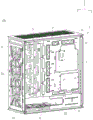
Fig. 1A is a schematic diagram of a computer case 100 according to an embodiment of the invention from a perspective. Fig. 1B is a schematic diagram of the computer case 100 of fig. 1A from another perspective. Fig. 1C is a schematic diagram of the computer case 100 of fig. 1A from another perspective.
Referring to fig. 1A, fig. 1B and fig. 1C, the computer case 100 includes a frame 1, a motherboard bracket 2 and a motherboard extension bracket 3. The frame 1 includes a front plate 11, a rear plate 12, a top plate 13, and a bottom plate 14. The front plate 11 and the rear plate 12 are disposed opposite to each other and parallel to each other, and the top plate 13 and the bottom plate 14 are disposed opposite to each other and parallel to each other. The front plate 11 and the rear plate 12 are connected between a top plate 13 and a bottom plate 14, respectively. Thus, the front plate 11, the rear plate 12, the top plate 13 and the bottom plate 14 form a hollow frame, which defines an accommodating space 17 (shown in fig. 1B) inside the computer case 100. In some embodiments, the computer case 100 may further include an L-shaped shielding plate 18 disposed in the accommodating space 17 of the computer case 100 to separate the accommodating space 17 into the first space 15 and the second space 16. In detail, the L-shaped shielding plate 18 includes a horizontal portion 181 and a side portion 182 connected to the horizontal portion 181. Side 182 is disposed parallel to motherboard bracket 2 and side 182 connects front panel 11, rear panel 12, and bottom panel 14. The horizontal portion 181 is disposed parallel to the top plate 13 and the bottom plate 14 and between the top plate 13 and the bottom plate 14, two sides of the horizontal portion 181 are connected to the front plate 11 and the rear plate 12, and the other two sides of the horizontal portion 181 are connected to the main board frame 2 and the side portion 182. The first space 15 may be defined by a space surrounded by the horizontal portion 181, the side portion 182, the bottom plate 14 and the main board frame 2, and the second space 16 may be defined by a space surrounded by the horizontal portion 181, the top plate 13, the front plate 11 and the rear plate 12. Further, by changing the shape of the shutter 18, the first space 15 can also communicate with the second space 16.
One or more fans 71 may be optionally mounted on the front panel 11, the back panel 12, the top panel 13 and/or the bottom panel 14 to remove heat from the interior of the computer case 100 to prevent temporary or permanent failure of the electronic components due to internal overheating. The one or more fans 71 are, for example, fans having a size of 140 millimeters (mm), but not limited thereto. In this embodiment, the top plate 13 can be used for placing three 140 millimeter (mm) fans 71, the front plate 11 can be used for placing three 140 mm fans 71, the rear plate 12 can be used for placing one 140 mm fan 71, and the bottom plate 11 can be used for placing two 140 mm fans 71, so that nine 140 mm fans 71 can be placed in the computer case 100, the thermal convection level of the case is improved, and the heat dissipation effect required by over-clocking of players is met. In one embodiment, the rear plate 12 may have a slide rail 121 thereon, so that the fan 71 on the rear plate 12 can slide on the slide rail 121, and a user can adjust the position of the fan 71 up and down according to the usage environment. In other embodiments, water cooling rows may be attached to the front panel 11, the rear panel 12, the top panel 13 and/or the bottom panel 14, depending on the needs of the user.
The main board support 2 abuts the top plate 13 and the rear plate 12 for carrying the main board 6. The motherboard 6 can be a Mini-ITX motherboard, an ATX motherboard or an E-ATX motherboard, but not limited thereto.
The motherboard extension bracket 3 is connected to the motherboard bracket 2, and can be used for carrying some peripheral devices required by users, such as a hard disk and/or a heat sink. In the present invention, the assembly position of the motherboard extending bracket 3 is changeable, and the motherboard extending bracket can be switched between a first position and a second position.
When the motherboard extension bracket 3 is located at the first position, the motherboard extension bracket 3 is connected between the motherboard bracket 2 and the front plate 11, as shown in the position of the motherboard extension bracket 3 shown by the solid line in fig. 1A, 1B and 1C. Specifically, when the motherboard extension bracket 3 is located at the first position, the motherboard extension bracket 3 is parallel to the motherboard bracket 2, and two sides of the motherboard extension bracket 3 are respectively connected to the motherboard bracket 2 and the front plate 11. Thus, the main board frame 2, the main board extension frame 3, the top plate 13, the front plate 11, the rear plate 12 and the horizontal portion 181 may define the second space 16.
When the motherboard extension bracket 3 is located at the second position, the motherboard extension bracket 3 is located in the second space 16, and is parallel to the front plate 11 and the rear plate 12 and located between the front plate 11 and the rear plate 12, as shown by the position of the motherboard extension bracket 3 shown by the dotted line in fig. 1A, 1B and 1C. Specifically, when the main board extension bracket 3 is located at the second position, two ends of the main board extension bracket 3 abut against the top plate 13 and the horizontal portion 181, and one side of the main board extension bracket 3 is connected to the main board bracket 2, so that the second space 16 is further divided into the first subspace 161 and the second subspace 162. The first sub-space 161 may be defined by a space surrounded by the top plate 13, the front plate 11, the horizontal portion 181 and the main board extending frame 3, and the first sub-space 161 may be in communication with the first space 15. The second sub-space 162 may be defined by a space surrounded by the top plate 13, the rear plate 12, the main board support 2, the horizontal portion 181 and the main board extension support 3, and the second sub-space 162 may communicate with the first space 15.
When the motherboard extension bracket 3 is located at the different positions, the motherboard extension bracket 3 can be used for carrying different peripheral devices respectively. By changing the assembly position of the motherboard extension bracket 3, a user can install the required peripheral devices on the motherboard extension bracket 3 according to the requirements.
In the embodiment shown in fig. 1A, 1B and 1C, the motherboard extension bracket 3 is detachably connected to the motherboard bracket 2. Furthermore, the user needs to disassemble the motherboard extending bracket 3 from the motherboard bracket 2, and after the position of the motherboard extending bracket 3 is converted, the motherboard extending bracket 3 is connected with the motherboard bracket 2, that is, the motherboard extending bracket 3 is converted from the first position to the second position, but the invention is not limited thereto. For example, in another embodiment, the motherboard extension bracket 3 may be pivotally connected to the motherboard bracket 2 in a pivoting manner, so that the motherboard extension bracket 3 can also be switched between the first position and the second position.
Fig. 2A is an exploded view of the extended motherboard bracket 3 of the computer case 100 in the first position according to an embodiment of the invention. Fig. 2B is an assembly diagram of the computer case 100 of fig. 2A. Fig. 2C is an exploded view of the computer case 100 of fig. 2A from another perspective. Fig. 2D is an assembly diagram of the computer case 100 of fig. 2C.
To clearly show how the motherboard extending bracket 3 is connected to the motherboard bracket 2 in the first position, please refer to fig. 2A, fig. 2B, fig. 2C and fig. 2D together. The main board bracket 2 may include a bracket main body 21 and a first bridging portion 22 connected thereto. The first bridging portion 22 is formed by bending the side edge of the motherboard bracket 2 at an angle, for example, 45 degrees. The first bridging portion 22 includes a bridging surface 22S, and the bridging surface 22S is a surface of the first bridging portion 22 that forms an angle of 45 degrees with the stent main body 21.
The main board extension bracket 3 may include an extension bracket main body 31 and a second lap portion 32 connected. The second connecting part 32 is formed by bending the side of the motherboard extension bracket 3 at an angle, for example, 45 degrees. The second overlapping portion 32 includes a first surface 32S1 and a second surface 32S2, and the first surface 32S1 and the second surface 32S2 are opposite sides of the second overlapping portion 32. The first surface 32S1 is a surface of the second overlapping portion 32 forming an angle of 45 degrees with the extension bracket main body 31, and the second surface 32S2 is a surface of the second overlapping portion 32 forming an angle of 135 degrees with the extension bracket main body 31.
When the motherboard extension bracket 3 is to be set at the first position, the user can make the first surface 32S1 of the second lap joint 32 of the motherboard extension bracket 3 face the lap surface 22S of the first lap joint 22 of the motherboard bracket 2, and combine the second lap joint 32 and the first lap joint 22 by the locking element 4. The locking element 4 is, for example, a screw or any element that allows the motherboard extension bracket 3 to be detachably connected to the motherboard bracket 2 without damaging its structure. When the motherboard extension bracket 3 is located at the first position, the first surface 32S1 of the second lap 32 of the motherboard extension bracket 3 is overlapped against the lap surface 22S of the first lap 22 of the motherboard bracket 2.
Fig. 3 is a schematic diagram of the computer case 100 of fig. 2A in a first position of the motherboard extending bracket 3 with the hard disk 81 attached. Referring to fig. 3, if the user has a need to install a hard disk, for example, a hard disk of 3.5 inches or 2.5 inches, but not limited thereto, the user can install a hard disk 81 on the motherboard extending bracket 3 located at the first position. In addition, in one embodiment, the user can also choose to assemble the disk set 82 on the base plate 14, such that the disk set 82 is assembled in the first space 15. The disk pack 82 may be screwed to the base plate 14. In another embodiment, the bottom plate 14 may have a slide rail, and the hard disk set 82 can slide on the slide rail to move to any position on the bottom plate 14, so that a user can freely adjust the setting position of the hard disk set 82 according to the space plan.
Fig. 4A is a schematic view of the computer case 100 of fig. 2A in a first position of the motherboard extending bracket 3 with the fan 71 and the water cooling bar 73. Fig. 4B is a schematic diagram of the computer case 100 of fig. 4A from another perspective. Referring to fig. 4A and 4B, if a user needs to dissipate heat, the fan 71 and the water cooling bank 73 may be assembled on the extended motherboard bracket 3 at the first position, such that the fan 71 and the water cooling bank 73 are assembled in the first space 15 and the second space 16. In addition, if the user needs to add a hard disk and dissipate heat, the hard disk set 82 shown in fig. 3 can be assembled on the bottom plate 14 in the first space 15.
Fig. 5A is an exploded view of the motherboard extending stand 3 of the computer case 100 in the second position according to another embodiment of the invention. Fig. 5B is an assembly diagram of the computer case 100 of fig. 5A. Fig. 5C is an exploded view of the computer case 100 of fig. 5A from another perspective. Fig. 5D is an assembly diagram of the computer case 100 of fig. 5C.
To clearly show how the motherboard extending bracket 3 is connected to the motherboard bracket 2 in the second position, please refer to fig. 5A, 5B, 5C and 5D. When the motherboard extension bracket 3 is to be switched from the first position to the second position, the user can remove the locking element 4 (e.g., screw) to detach the motherboard extension bracket 3 from the motherboard bracket 2. Then, the motherboard extension bracket 3 is turned over by 180 degrees up and down. As shown in fig. 5A and 5C, the motherboard extension stand 3 may include a protrusion 33, and the protrusion 33 protrudes from the extension stand body 31 toward the negative Z-axis direction and is located on one side of the extension stand body 31 toward the negative Y-axis direction. The computer case 100 includes an engaging portion 5 corresponding to the protruding portion 33, for example, a groove corresponding to the shape of the protruding portion 33. The engaging portion 5 is provided on the horizontal portion 181 of the shade 18, for example, but not limited thereto. For example, the engaging portion 5 may be alternatively disposed on other structures of the computer case 100. When the motherboard extension bracket 3 is turned up and down by 180 degrees, the protrusion 33 originally facing the top board 13 faces the bottom board 14 instead, and the second surface 32S2 of the second lap portion 32 of the motherboard extension bracket 3 faces the lap surface 22S of the first lap portion 22 of the motherboard bracket 2. At this time, the user can apply the second surface 32S2 to the overlapping surface 22S, and combine the second overlapping portion 32 with the first overlapping portion 22 by the locking element 4, and the protrusion 33 can also be engaged in the engaging portion 5. Thereby, the board extension bracket 3 is disposed at the second position, and the second surface 32S2 of the second lap 32 of the board extension bracket 3 is overlapped against the lap surface 22S of the first lap 22 of the board bracket 2.
Fig. 6A is a schematic view of the motherboard extending stand 3 of the computer case 100 of fig. 5A in a second position for carrying the fan 72. Fig. 6B is a schematic diagram of the computer case 100 of fig. 6A from another perspective. Referring to fig. 6A and 6B, if a user needs to dissipate heat, one or more fans 72, such as a fan with a size of 120 millimeters (mm), may be mounted on the motherboard extending frame 3 at the second position. As shown in fig. 6B, the fans 72 are assembled in the second sub-space 162 and directly blow airflow toward the heat generating components (such as the cpu, the graphic processor, the memory …, etc.) disposed on the motherboard 6, thereby enhancing heat convection near the motherboard 6, so that heat flow generated by the heat generating components can be exhausted through the fans 71 of the rear plate 12 and the top plate 13, thereby achieving the effect of rapid heat dissipation.
In addition, if the user has both the requirement of heat dissipation and the requirement of installing a hard disk, the hard disk set 82 shown in fig. 3 can be assembled on the base plate 14 in the first space 15. Alternatively, please refer to fig. 7, which is a schematic diagram of the computer case 100 of fig. 5A in which the motherboard extending bracket 3 at the second position bears the hard disk 83. The user can assemble one or more hard disks 83 on the motherboard extending stand 3 located at the second position. These hard disks 83 are disposed in the first subspace 161 to efficiently utilize the existing space within the computer case 100. In detail, the main board extension bracket 3 further includes a mounting bracket 84, the mounting bracket 84 is located in the first sub-space 161 and is disposed parallel to the top board 13 and the bottom board 14, so that the hard disk 83 is mounted on the mounting bracket 84, in this embodiment, five mounting brackets 84 are provided, so that five hard disks 83 can be carried. In this embodiment, the fan 71 and the water cooling bank 73 are assembled on the front plate 11, and the fan 71 and the water cooling bank 73 are assembled in the first subspaces 161 of the first space 15 and the second space 16, but the invention is not limited to this configuration. Therefore, air flow can be fed from the front plate 11, the air pressure between the front plate 11 and the mainboard extension bracket 3 is enhanced, and the air flow is accelerated, so that the effect of quick heat dissipation is achieved.
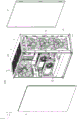
Fig. 8 is an exploded view of the frame 1 of the computer case 100 according to an embodiment of the invention, wherein the left and right sides are assembled by glass covers. When a user completes the installation of electronic components (e.g., motherboard, display card, power supply, etc.) and peripheral devices (e.g., hard disk, fan, etc.) inside the computer case 100 as required, the glass cover plates 9 may be disposed on the left and right sides of the frame 1 of the computer case 100 to be adjacent to the front plate 11, the rear plate 12, the top plate 13 and the bottom plate 14. The glass cover 9 may provide a perspective view of the interior of the computer case 100 to present a unique assembly style to different players.
According to the computer case provided by the above, a user can install required peripheral devices on the mainboard extension bracket according to the requirement of the user by changing the assembly position of the mainboard extension bracket without purchasing an additional fixing bracket for installation.
In addition, when the motherboard extension bracket is located at different assembly positions (such as a first position and a second position), the motherboard extension bracket can be respectively used for carrying different peripheral devices. In some embodiments, the motherboard extension bracket can be used for bearing not only a hard disk but also a heat dissipation device. Or the mainboard extension bracket can be used for bearing the hard disk and the heat dissipation device. Therefore, the computer case provided by the above can be suitable for various requirements of users.
The present invention is capable of other embodiments, and various changes and modifications may be made by one skilled in the art without departing from the spirit and scope of the invention as defined in the appended claims.
Claims (7)
1. A computer case, comprising:
a frame, including a front plate, a back plate, a top plate and a bottom plate, the front plate and the back plate are oppositely arranged and parallel to each other, the top plate and the bottom plate are oppositely arranged and parallel to each other, the front plate and the back plate are respectively connected between the top plate and the bottom plate;
a main board support adjacent to the top board and the back board; and
the mainboard extension bracket is connected with the mainboard bracket and is provided with a first position or a second position;
when the mainboard extension bracket is positioned at the first position, the mainboard extension bracket is arranged in parallel with the mainboard bracket, and two sides of the mainboard extension bracket are respectively connected with the mainboard bracket and the front plate;
when the mainboard extension bracket is positioned at the second position, the mainboard extension bracket is parallel to the front plate and the rear plate, the mainboard extension bracket is positioned between the front plate and the rear plate, the side edge of the mainboard bracket comprises a first lap joint part formed by bending, the side edge of the mainboard extension bracket comprises a second lap joint part formed by bending, the first lap joint part comprises a lap joint surface, and the second lap joint part comprises a first surface and a second surface which are opposite; when the extension bracket of the mainboard is positioned at the first position, the first surface is overlapped on the lapping surface; when the extension bracket of the mainboard is positioned at the second position, the second surface is overlapped on the lapping surface.
2. The computer case of claim 1, wherein when the motherboard extension bracket is in the first position, the motherboard extension bracket is used for carrying a hard disk or a heat sink; when the mainboard extension bracket is positioned at the second position, the mainboard extension bracket is used for bearing the hard disk and/or the heat dissipation device.
3. The computer case of claim 1, further comprising an L-shaped cover, wherein the frame defines an accommodation space, and the cover is disposed in the accommodation space to divide the accommodation space into a first space and a second space.
4. The computer case of claim 3, wherein the L-shaped shield includes a horizontal portion and a side portion, the horizontal portion, the side portion, the bottom plate and the motherboard bracket define the first space, a hard disk set is located in the first space, and the bottom plate is further used for carrying the hard disk set.
5. The computer case of claim 4, wherein the horizontal portion of the cover further comprises a locking portion, the extended motherboard bracket further comprises a protrusion corresponding to the locking portion;
when the mainboard extension bracket is positioned at the first position, the protruding part faces the top plate of the frame;
when the mainboard extension bracket is located at the second position, the protruding part faces the bottom plate of the frame and is arranged in the clamping part.
6. The computer case of claim 1, further comprising two glass covers respectively disposed on the left and right sides of the frame to abut the front plate, the back plate, the top plate and the bottom plate.
7. The computer chassis of claim 1, wherein the motherboard extender bracket further comprises at least one mounting bracket disposed parallel to the top and bottom panels when the motherboard extender bracket is in the second position, the at least one mounting bracket for carrying a hard disk.
Priority Applications (2)
| Application Number | Priority Date | Filing Date | Title |
|---|---|---|---|
| CN201810653137.5A CN110632985B (en) | 2018-06-22 | 2018-06-22 | Computer cabinet |
| US16/362,843 US10514733B1 (en) | 2018-06-22 | 2019-03-25 | Computer case |
Applications Claiming Priority (1)
| Application Number | Priority Date | Filing Date | Title |
|---|---|---|---|
| CN201810653137.5A CN110632985B (en) | 2018-06-22 | 2018-06-22 | Computer cabinet |
Publications (2)
| Publication Number | Publication Date |
|---|---|
| CN110632985A CN110632985A (en) | 2019-12-31 |
| CN110632985B true CN110632985B (en) | 2023-03-31 |
Family
ID=68967026
Family Applications (1)
| Application Number | Title | Priority Date | Filing Date |
|---|---|---|---|
| CN201810653137.5A Active CN110632985B (en) | 2018-06-22 | 2018-06-22 | Computer cabinet |
Country Status (2)
| Country | Link |
|---|---|
| US (1) | US10514733B1 (en) |
| CN (1) | CN110632985B (en) |
Families Citing this family (3)
| Publication number | Priority date | Publication date | Assignee | Title |
|---|---|---|---|---|
| TWD201841S (en) * | 2019-05-24 | 2020-01-01 | 威剛科技股份有限公司 | Part of computer case |
| TWM584447U (en) * | 2019-05-24 | 2019-10-01 | 華碩電腦股份有限公司 | Computer housing |
| TWD201842S (en) * | 2019-05-24 | 2020-01-01 | 威剛科技股份有限公司 | Part of computer case |
Citations (6)
| Publication number | Priority date | Publication date | Assignee | Title |
|---|---|---|---|---|
| JPH1075508A (en) * | 1996-08-30 | 1998-03-17 | Mitsubishi Electric Corp | Apparatus attachment panel for switchboard |
| JP3017194B1 (en) * | 1998-12-10 | 2000-03-06 | 日本電気株式会社 | Mounting structure of multilayer electronic circuit package |
| CN202159295U (en) * | 2011-06-17 | 2012-03-07 | 傅文彬 | Machine box structure capable of improving radiation efficiency of computer heat sources |
| CN204180438U (en) * | 2014-09-30 | 2015-02-25 | 四川璧虹广播电视新技术有限公司 | A kind of optical node integrated box and mounting plates structure thereof |
| CN206353279U (en) * | 2017-01-04 | 2017-07-25 | 广州市中科电脑设备有限公司 | A kind of improved structure computer housing |
| CN206400433U (en) * | 2017-01-10 | 2017-08-11 | 东莞市金河田实业有限公司 | It is a kind of effectively to utilize the computer cabinet of inner space |
Family Cites Families (2)
| Publication number | Priority date | Publication date | Assignee | Title |
|---|---|---|---|---|
| JP4364939B1 (en) * | 2009-04-21 | 2009-11-18 | 新光電気工業株式会社 | Electronic equipment |
| JP4988029B2 (en) * | 2010-11-30 | 2012-08-01 | 株式会社東芝 | Electronics |
-
2018
- 2018-06-22 CN CN201810653137.5A patent/CN110632985B/en active Active
-
2019
- 2019-03-25 US US16/362,843 patent/US10514733B1/en active Active
Patent Citations (6)
| Publication number | Priority date | Publication date | Assignee | Title |
|---|---|---|---|---|
| JPH1075508A (en) * | 1996-08-30 | 1998-03-17 | Mitsubishi Electric Corp | Apparatus attachment panel for switchboard |
| JP3017194B1 (en) * | 1998-12-10 | 2000-03-06 | 日本電気株式会社 | Mounting structure of multilayer electronic circuit package |
| CN202159295U (en) * | 2011-06-17 | 2012-03-07 | 傅文彬 | Machine box structure capable of improving radiation efficiency of computer heat sources |
| CN204180438U (en) * | 2014-09-30 | 2015-02-25 | 四川璧虹广播电视新技术有限公司 | A kind of optical node integrated box and mounting plates structure thereof |
| CN206353279U (en) * | 2017-01-04 | 2017-07-25 | 广州市中科电脑设备有限公司 | A kind of improved structure computer housing |
| CN206400433U (en) * | 2017-01-10 | 2017-08-11 | 东莞市金河田实业有限公司 | It is a kind of effectively to utilize the computer cabinet of inner space |
Also Published As
| Publication number | Publication date |
|---|---|
| US10514733B1 (en) | 2019-12-24 |
| US20190391622A1 (en) | 2019-12-26 |
| CN110632985A (en) | 2019-12-31 |
Similar Documents
| Publication | Publication Date | Title |
|---|---|---|
| US8248780B2 (en) | All-in-one computer | |
| CN110632985B (en) | Computer cabinet | |
| US7324338B1 (en) | Heat dissipating apparatus of a computer system | |
| US8089763B2 (en) | Heat-dissipating assembly for server | |
| US9232171B2 (en) | Electronic apparatus with cooling unit | |
| US8164900B2 (en) | Enclosure of electronic device | |
| US9271409B2 (en) | Terminal device | |
| US20120305745A1 (en) | Fan mounting apparatus for an electronic device | |
| US20110299239A1 (en) | Computer Case with Upwardly Oriented Add-On Cards and Vertical Airflow | |
| CN100541390C (en) | Multidirectional configurable architecture for multi-processor system | |
| US20110122576A1 (en) | Computer | |
| US8254119B2 (en) | Host computer attached to monitor | |
| US20110122566A1 (en) | Computer | |
| CN101644944A (en) | Computer | |
| US20110122564A1 (en) | Computer | |
| US8154865B2 (en) | Computer including a disk drive, motherboard and fan | |
| JP5267937B2 (en) | Electronics | |
| TWM586034U (en) | Supporting rack | |
| US10890956B1 (en) | System and method for versatile device mounting in a desktop information handling system | |
| CN108073233B (en) | Electronic device | |
| US9710027B2 (en) | Chassis design and component layout for a mini-ITX format computer | |
| CN219497008U (en) | Small file server | |
| CN212659032U (en) | Industrial all-in-one machine | |
| TWM417747U (en) | Computer case | |
| TWI498707B (en) | All-in-one computer |
Legal Events
| Date | Code | Title | Description |
|---|---|---|---|
| PB01 | Publication | ||
| PB01 | Publication | ||
| SE01 | Entry into force of request for substantive examination | ||
| SE01 | Entry into force of request for substantive examination | ||
| GR01 | Patent grant | ||
| GR01 | Patent grant |