CN1106104C - Communication terminal - Google Patents
Communication terminal Download PDFInfo
- Publication number
- CN1106104C CN1106104C CN95191036A CN95191036A CN1106104C CN 1106104 C CN1106104 C CN 1106104C CN 95191036 A CN95191036 A CN 95191036A CN 95191036 A CN95191036 A CN 95191036A CN 1106104 C CN1106104 C CN 1106104C
- Authority
- CN
- China
- Prior art keywords
- key
- communication terminal
- mentioned
- device body
- input
- Prior art date
- Legal status (The legal status is an assumption and is not a legal conclusion. Google has not performed a legal analysis and makes no representation as to the accuracy of the status listed.)
- Expired - Fee Related
Links
Images


Classifications
-
- H—ELECTRICITY
- H04—ELECTRIC COMMUNICATION TECHNIQUE
- H04M—TELEPHONIC COMMUNICATION
- H04M1/00—Substation equipment, e.g. for use by subscribers
- H04M1/02—Constructional features of telephone sets
- H04M1/03—Constructional features of telephone transmitters or receivers, e.g. telephone hand-sets
-
- H—ELECTRICITY
- H04—ELECTRIC COMMUNICATION TECHNIQUE
- H04M—TELEPHONIC COMMUNICATION
- H04M1/00—Substation equipment, e.g. for use by subscribers
- H04M1/02—Constructional features of telephone sets
- H04M1/0202—Portable telephone sets, e.g. cordless phones, mobile phones or bar type handsets
- H04M1/0206—Portable telephones comprising a plurality of mechanically joined movable body parts, e.g. hinged housings
- H04M1/0241—Portable telephones comprising a plurality of mechanically joined movable body parts, e.g. hinged housings using relative motion of the body parts to change the operational status of the telephone set, e.g. switching on/off, answering incoming call
- H04M1/0245—Portable telephones comprising a plurality of mechanically joined movable body parts, e.g. hinged housings using relative motion of the body parts to change the operational status of the telephone set, e.g. switching on/off, answering incoming call using open/close detection
-
- H—ELECTRICITY
- H04—ELECTRIC COMMUNICATION TECHNIQUE
- H04M—TELEPHONIC COMMUNICATION
- H04M1/00—Substation equipment, e.g. for use by subscribers
- H04M1/26—Devices for calling a subscriber
- H04M1/27—Devices whereby a plurality of signals may be stored simultaneously
- H04M1/274—Devices whereby a plurality of signals may be stored simultaneously with provision for storing more than one subscriber number at a time, e.g. using toothed disc
- H04M1/2745—Devices whereby a plurality of signals may be stored simultaneously with provision for storing more than one subscriber number at a time, e.g. using toothed disc using static electronic memories, e.g. chips
- H04M1/27453—Directories allowing storage of additional subscriber data, e.g. metadata
- H04M1/2746—Sorting, e.g. according to history or frequency of use
-
- H—ELECTRICITY
- H04—ELECTRIC COMMUNICATION TECHNIQUE
- H04M—TELEPHONIC COMMUNICATION
- H04M1/00—Substation equipment, e.g. for use by subscribers
- H04M1/26—Devices for calling a subscriber
- H04M1/27—Devices whereby a plurality of signals may be stored simultaneously
- H04M1/274—Devices whereby a plurality of signals may be stored simultaneously with provision for storing more than one subscriber number at a time, e.g. using toothed disc
- H04M1/2745—Devices whereby a plurality of signals may be stored simultaneously with provision for storing more than one subscriber number at a time, e.g. using toothed disc using static electronic memories, e.g. chips
- H04M1/27467—Methods of retrieving data
- H04M1/2747—Scrolling on a display
-
- H—ELECTRICITY
- H04—ELECTRIC COMMUNICATION TECHNIQUE
- H04M—TELEPHONIC COMMUNICATION
- H04M1/00—Substation equipment, e.g. for use by subscribers
- H04M1/72—Mobile telephones; Cordless telephones, i.e. devices for establishing wireless links to base stations without route selection
- H04M1/724—User interfaces specially adapted for cordless or mobile telephones
-
- H—ELECTRICITY
- H04—ELECTRIC COMMUNICATION TECHNIQUE
- H04M—TELEPHONIC COMMUNICATION
- H04M1/00—Substation equipment, e.g. for use by subscribers
- H04M1/02—Constructional features of telephone sets
- H04M1/0202—Portable telephone sets, e.g. cordless phones, mobile phones or bar type handsets
- H04M1/0206—Portable telephones comprising a plurality of mechanically joined movable body parts, e.g. hinged housings
- H04M1/0208—Portable telephones comprising a plurality of mechanically joined movable body parts, e.g. hinged housings characterized by the relative motions of the body parts
- H04M1/0214—Foldable telephones, i.e. with body parts pivoting to an open position around an axis parallel to the plane they define in closed position
Landscapes
- Engineering & Computer Science (AREA)
- Signal Processing (AREA)
- Library & Information Science (AREA)
- Human Computer Interaction (AREA)
- Computer Networks & Wireless Communication (AREA)
- Telephone Set Structure (AREA)
- Mobile Radio Communication Systems (AREA)
Abstract
A terminal for communication provided with a microphone unit which can move between the place where the caller is present and which is away from the terminal main body and the place where the microphone unit is stored and which is near the main body. The terminal is further provided with a transmission-reception circuit which modulates signals outputted from the microphone unit and transmits them, and which demodulates received signals and outputs them, a loudspeaker which outputs the signals from the transmission-reception circuit as audible sounds, a detecting mechanism which detects the position of the microphone unit, and a controller which controls the input/output of sounds based on the detection signal of the detecting mechanism. The controller mutes the output signals of the microphone unit when the detecting mechanism detects that the microphone unit is at the storage place. Therefore, a muting mode can be set or canceled by moving the microphone unit. When a muting means is in a muting mode, hold tone is transmitted from the transmission-reception circuit so as to inform the caller that the line is busy.
Description
Technical field
The present invention relates to communication terminal, more particularly, relate to communication terminal with acoustic input dephonoprojectoscope and control device, acoustic input dephonoprojectoscope has the microphone unit of move operation between the talking position that can take out in the position that is incorporated in the device body side with from this reception position and can converse, and control device detects this acoustic input dephonoprojectoscope for the position of body and according to the input and output of its detected state control sound.
Background technology
Current, the hand-phone system that utilizes radiolink is just in practicability.In this hand-phone system,, seek to be used for the multifunction of the communication terminal of this system for carrying out the transmission form of multiple information.The communication terminal that is used for this hand-phone system has and accesses the telephone number that is stored in advance in the memory cell that is loaded on device body and the automatic dialing of automatically calling out and use function such as shorten that dialing is called out.Also possesses the phonebook function that makes telephone number deposit memory cell in.
Also have, be used to the communication terminal of hand-phone system owing to be hand-held the use, so small-sized and light-weighted requirement is very high.Therefore, in this communication terminal, the slim switchization by dial key, the exploitation of heavy-duty battery, electronic unit highly integrated etc. realized lightweight significantly.
Yet communication terminal need be configured to separate one section distance that is equivalent to mouth and ear to transmitter and receiver in the transceiver state, and overall size just depends on the interval of transmitter and receiver.That is, in communication terminal, the air line distance of transmitter and receiver is set at about about 13.5cm~14.3cm, and its angle initialization is comparatively desirable about 23.3 °~13.4 ° in addition.Be when satisfying such design condition, to realize miniaturization, for example use the communication terminal that constitutes microphone unit and receiver part and can constitute these 2 part foldings totally cutting apart.The communication terminal of this energy folding is not when carrying out the carrying of transceiver, arrive so-called pocket size by folding microphone unit and the miniaturization of receiver part, when transceiver, by opening microphone unit and receiver part, the distance of transmitter and receiver can be expanded to the degree of the distance of mouth and ear.
Disclosure of an invention
The object of the present invention is to provide the miniaturization of implement device body and the communication terminal that multiple function also can be easily carried out in lightweight.
Another object of the present invention is to provide and not only realizes the multifunction of operating function but also do not increase being used to carry out each function operations key, and the communication terminal of miniaturization that can the implement device body.
A further object of the present invention is to provide a kind of communication terminal, its utilizes the move operation as the transmitter of acoustic input dephonoprojectoscope that can change its position with respect to device body, seeks to improve operability by the control of carrying out the sound input and output during conversation.
Also can be notified to the other side to the information that is in talking state even another purpose of the present invention is to provide a kind of transmission of voice signal to be in noise-limited condition, thereby can carry out the communication terminal of satisfactory transceiver.
Another object of the present invention is to provide a kind of communication terminal, operation by transmitter makes that when conversing the sound from transmitter or receiver being carried out noise elimination handles, therefore, thus the transceiver of unnecessary sound seeks to improve the transceiver convenience can limit transceiver the time.
The communication terminal relevant with the present invention that proposes has for achieving the above object: when conversation, move to from the position of apparatus adjacent body the position of separating device body acoustic input dephonoprojectoscope, the signal that receives as the voice output of sub-audible sound output, detect the testing agency of acoustic input dephonoprojectoscope position, according to the control device of controlling the sound input and output from the detection signal of testing agency.
This control device has according to the static limiter that carries out the noise elimination processing from the detection signal handle of testing agency from the output of acoustic input dephonoprojectoscope or voice output.This static limiter illustrates at the detection signal from testing agency and carries out the noise elimination action when acoustic input dephonoprojectoscope is positioned at the position of apparatus adjacent body.
In addition, relevant with the present invention communication terminal also has the generating apparatus that generates reservation sound when static limiter is in the noise elimination operate condition.The reservation sound that is generated by generating apparatus is sent to the other side.
The acoustic input dephonoprojectoscope of the communication terminal relevant with the present invention is to constitute by be mounted to spiral arm that can rotate and the microphone unit that is installed on the spiral arm between the talking position of the reception position of apparatus adjacent body and separating device body.
In addition, testing agency have be installed in the spiral arm that constitutes acoustic input dephonoprojectoscope and in the device body either party the detected unit that constitutes by magnet and be installed in the opposing party's the detecting unit that constitutes by Hall element.
Also have, and the present invention's communication terminal of throwing away the pass has constitute the microphone unit that can rotate between the reception position of the talking position of separating device body and adjacent body, output signal from microphone unit is applied send again after the modulation treatment that is used to send and the signal that receives is applied after the demodulation process transceiver circuit of output again, the speaker unit of exporting as sub-audible sound from the output signal of transceiver circuit, detect the testing agency of the position of microphone unit, according to the control device of controlling the input and output of sound from the detection signal of testing agency.This control device have testing agency detect microphone unit when being in reception position with respect to device body carry out the static limiter that noise elimination is handled from the output signal of microphone unit.
This communication terminal also has the generating apparatus that generates reservation sound when static limiter is in the noise elimination operate condition, supplies with transceiver circuit by the reservation sound that generating apparatus generates, and sends from transceiver circuit.
Further purpose of the present invention and the advantage that realizes by the present invention from following will be further clear and definite with reference to the illustrated specific embodiment of accompanying drawing.
The simple declaration of accompanying drawing
Fig. 1 illustrates the biopsy cavity marker devices oblique view that transmitter is turned to the state of release position from device body.
Fig. 2 illustrates the plane graph that transmitter is accommodated in the state of device body.
Fig. 3 is the block diagram that the circuit structure that is arranged on communication terminal inside is shown.
Fig. 4 is the sketch for the small-sized font of explanation.
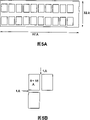
Fig. 5 is the sketch for the explanation boxboard.
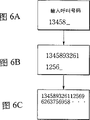
Fig. 6 is the state transition diagram that switches font for explanation according to the difference of input characters number.
Fig. 7 illustrates to have used Menu key to switch the sketch of display frame.
Fig. 8 illustrates to have used clear key to switch the sketch of display frame.
Fig. 9 is the simple plane graph that the roughly mechanism of rotating operation key is shown.
Figure 10 is the plane graph that the rotary encoder structure is shown.
Figure 11 is the signal waveforms that illustrates from the waveform of rotary encoder output.
Figure 12 illustrates to have used the rotating operation key to switch the state transition diagram of display frame.
Figure 13 is the flow chart that illustrates corresponding to the operating sequence of the operation input mechanism of the position of transmitter.
Figure 14 is the state transition diagram for the various calling sequences of explanation.
Figure 15 is the state transition diagram for the various calling sequences of explanation.
Figure 16 is the state transition diagram that illustrates from the calling sequence of telephone directory book.
Figure 17 is the character arranging figure that character arranging in the telephone directory book is shown.
Figure 18 is the state transition diagram that has used the numerical key retrieval for explanation.
Figure 19 illustrates the state transition diagram that reverts to tabulation display frame situation from details display frame.
Figure 20 is the state transition diagram that new login order example on the telephone directory book picture is shown.
Figure 21 is the state transition diagram that new login order example on the telephone directory book picture is shown.
Figure 22 is the state transition diagram that is illustrated in editor's order of the display frame that shows on the telephone directory book picture.
Figure 23 is the state transition diagram that menu screen is shown.
Figure 24 is the state transition diagram that the detailed display frame of mode initialization picture is shown.
Figure 25 illustrates the state transition diagram of various mode initializations with the detailed display frame of picture.
Figure 26 illustrates the state transition diagram that the detailed display frame of picture is set in ring.
Figure 27 is the state transition diagram that the detailed display frame of sound volume setting picture is shown.
Figure 28 is the state transition diagram for the explanation rolling function.
Figure 29 is the state transition diagram for the explanation rolling function.
Figure 30 illustrates the state transition diagram that switches example from details display frame to other picture.
The optimal morphology that carries out an invention
Specific embodiment with reference to the description of drawings communication terminal relevant with the present invention.
The communication terminal relevant with the present invention as shown in Figures 1 and 2, handle assembly body 1, have the side that is provided in this device body 1 rotationally constitute the microphone unit 13 of acoustic input dephonoprojectoscope transmitter 2, and integrally charging apparatus body 1 and in battery is housed battery case 3 formation that combines, overall shape forms the size of hand sizes.
A side of the length direction of this device body 1 is formed the face of general planar, as described later, constitutes the part that sets of transmitter 2.In addition, the face with having set transmitter 2 of device body 1 perpendicular on the plane setting retractile antenna 8.And then, be positioned at the upper end side of the another side of device body 1 length direction, as shown in Figures 1 and 2, form and roughly be the expansion part 5 that the expansion of circular-arc ground forms.
As mentioned above, transmitter 2, antenna 8 are set to being positioned at a side of device body 1, the communication terminal relevant with the present invention that forms circular-arc expansion part 5 in another side of device body 1 and constitute is during by left-handed, because expansion part 5 is positioned at thumb bottom while transmitter 2 and antenna 8 is positioned at other finger tip, so can grip with stable status with left hand reliably.
And, the face side of device body 1 and form the relative zone, position of expansion part 5, as shown in Figures 1 and 2, what constitute speaker unit 7 that broad warp ground expansion forms sets part 9.Speaker unit 7 is installed on the circuit substrate and is contained in the device body 1.Setting the setting on the part 9 of this speaker unit 7, forming the rounded recess 9a of a part of pressing close to ear when using.On the bottom surface of this recess 9a, wearing a plurality of louver 7a.
From setting of device body 1 middle body of face side of speaker unit 7 to the zone of below one side, setting a plurality of operation keyss that constitute operation input mechanism 10.These a plurality of operation keyss by numerical key 10b, " # " key 10c of power key 10a, " 0 "~" 9 ", "
*" key 10d, send key 10e, end key 10f, Menu key 10g, clear key 10h and constitute.These each key 10a~10h are made of thin film type switch, are loaded on the circuit substrate of device body 1 in being electrically connected to via having flexual stube cable.
In addition, the relative side in the position with having set antenna 8 on plane on the device body 1 is provided with the record button 10i that constitutes the operation input mechanism.And then another side of device body 1 is setting the rotating operation key 10j that constitutes the operation input mechanism near being positioned at the root of expansion part 5.
Also have, be provided on the side of device body 1 transmitter 2 as shown in Figures 1 and 2, have roughly the spiral arm part 12 with the long chi shape of the height equal lengths of device body 1, taking in microphone unit 13 in the front of this spiral arm part 12.The spiral arm part 12 of taking in this microphone unit 13 is formed by rubber-like materials such as rubber.In addition,, setting the spring members of formations such as metal wire spring, making when this spiral arm part 12 flexible deformations, to be easy to recover in spiral arm part 12 inside that form by elastomeric material.In addition, wearing sound collecting hole 13a on the part of the relative microphone unit 13 of spiral arm part 12.
And on a side of device body 1, when transmitter 2 rotating operations during to the reception position that extends along 1 one sides of device body, the maintenance body 15 that constitutes the containing section of taking in this transmitter 2 is arranged to protrude in the latter half 6 of casing.It is L-shaped that this maintenance body 15 forms section, assigns to load and unload the transmitter 2 that rotates along a side of device body 1 by the opening portion of its facing device body 1 face side.Keep body 15 that transmitter 2 is taken in remaining on reception position, can seek to protect the transmitter 2 of spiral arm part 12 by being provided with like this with long chi shape.
In addition, be provided with the upper end side that is arranged in 1 one sides of device body, be incorporated in the transmitter 2 that keeps body 15 and combine, this transmitter 2 is latched in the blocking mechanism 16 of reception position.As shown in Figure 2, this blocking mechanism 16 by: thereby thereby from 1 one sides of device body the lockweight 18 that combines in conjunction with recess 17 outstanding and that form with the face relative with a side of device body 1 at transmitter 2, make this lockweight 18 from 1 one sides of device body outstanding obtain the leaf spring 19 of potential energy and be arranged on 1 one sides of device body as shown in Figure 1 lockweight 18 is drawn into remove device body 1 in transmitter 2 for operating mechanism 20 formations in order to the potential energy of resistance leaf spring 19 in conjunction with the combination of recess 17.By setting up locking to be accommodated in the blocking mechanism 16 that keeps the transmitter 2 in the body 15 like this, transmitter 2 is maintained the state that keeps in the body 15 that is accommodated in reliably, prevents the unexpected rotation that takes place reliably, therefore prevents misoperation reliably.
By blocking mechanism 16 lockings and be accommodated in the transmitter 2 that keeps in the body 15 and the potential energy of lockweight 18 resistance leaf springs 19 shifted in the device body 1 by slide operating mechanism 20, remove transmitter 2 for combination in conjunction with recess 17, removed the locking with respect to device body 1 thus, becoming to be the state that rotate along arrow A direction among Fig. 1 at the center with rotating support mechanism 14.At this moment, by in rotating support mechanism 14, setting spring members in advance and making it to have the rotator inertia that transmitter 2 is rotated along arrow A direction among Fig. 1, in case the then locking of unlocking mechanism 16, transmitter 2 just automatically rotates along the direction of the arrow A in Figure 1, as shown in Figure 1, microphone unit 13 being positioned at device body 1 isolates and outstanding position.
In addition, even be transmitter 2 supportings to make it make transmitter 2 have potential energy along having set spring members in the rotating support mechanism 14 that device body 1 rotates from the direction that keeps body 15 to rotate along the direction of the arrow A in Figure 1, because transmitter 2 is incorporated in when keeping in the body 15 by blocking mechanism 16 lockings when being in, so also can realize remaining on reliably reception position.
Also have, between device body 1 and transmitter 2, be provided with and detect the testing agency 21 of transmitter 2 with respect to the position of device body 1, detecting transmitter 2 is to be in the position that is contained, still to be rotated the talking position that makes microphone unit 13 leave and protrude in device body 1 with respect to device body 1.This testing agency 21 is made of Hall element 22 and magnetic 23, Hall element is provided on the side at the transmitter that turns to reception position 2 places of device body 1, magnetic 23 constitutes detected unit, be provided on the face relative of transmitter 2 with 1 one sides of device body, relative with Hall element 22 when transmitter 2 turns to reception position.Hall element 22 is provided in the device body 1.Face outside through the opening 24 that on 1 one sides of device body, forms.In addition, magnetic 23 uses magnet and flaky magnet, is installed in by modes such as joints on the face relative with 1 one sides of device body of transmitter 2.
And, testing agency 21 lies down along 1 one sides of device body and when being incorporated in the state that keeps in the body 15 when transmitter 2, staggered relatively by magnetic 23 and Hall element 22, detect magnetic flux by Hall element 22 from magnetic 23, output expression transmitter 2 is in the detection signal of reception position, turn to when keeping position that body 15 takes out at transmitter 2, magnetic flux from magnetic 23 is not detected by Hall element 22, thus, output expression transmitter 2 is removed and turns to the detection signal that makes the talking position that microphone unit 13 leaves from device body 1 from device body 1 side.
In addition, detect transmitter 2 and remove outside the use magnetic detection device, can also use optical detection apparatus with respect to the testing agency 21 of the position of device body 1.For example, can the luminous photoreactivation element that is subjected to be set, reflector plate be set, check, detect the position of transmitter 2 thus with respect to device body 1 from only not detected that light-emitting component is launched by photo detector in transmitter 2 sides in device body 1 side.
In addition, on the front that is provided with the operating mechanism 10 that constitutes by a plurality of operation keys 10a~10h of device body 1, as shown in Figures 1 and 2, setting the display unit 25 that constitutes by LCD etc. at the substantial middle position that sets between part 9 and the operating mechanism 10 of speaker unit 7.
Also have, setting the central arithmetic processing apparatus (CPU) 31 that constitutes control device by the interior circuit substrate that is loaded on device body 1.
CPU31 controls display units 25 via display unit drive circuit 32 as shown in Figure 3, shows the information that adapts with the instruction of importing from operating mechanism 10 with suitable big or small font.
In addition, as shown in Figure 3, among the detection signal input CPU31 from testing agency 21, the position of transmitter 2 with respect to device body 1 detected by this testing agency 21, that is, detecting transmitter 2 is to be in the position that is incorporated in the packaging container 15 that extends along a side of device body 1, still to be in to rotate from device body 1 and to make microphone unit 13 from position that device body 1 leaves.This detection signal uses as the control signal of control operation input mechanism 10 and transceiver circuit 35.
Here, the program that is stored among the ROM33 is imported among the CPU31 with the data that are read among the RAM34.And CPU31 moves according to the data that are stored in the program among the ROM33 and be read among the RAM.
In addition, be loaded on the transceiver circuit 35 in the device body 1 in CPU31 controls.
Be subjected to the transceiver circuit 35 of CPU31 control to have modulation/demodulation circuit 36, after applying modulation treatment, 36 pairs of corresponding voice signals of sound with the microphone unit 13 collection sounds of transmitter 2 of this modulation/demodulation circuit form the transmission signal, send via antenna 8, simultaneously, the received signal that receives via antenna 8 is applied demodulation process, resulting the other side's voice signal is outputed to speaker unit 7.And then, transceiver circuit 35 has digital signal processor (DSP) 37, this digital signal processor (DSP) 37 applies the voice signal from microphone unit 13 inputs according to the control signal from CPU31 and outputs to modulation/demodulation circuit 36 after prearranged signal is handled, outputing to speaker unit 7 by the voice signal after the modulation/demodulation circuit demodulation.This DSP37 has from the voice signal of microphone unit 13 input and the amplifying circuit that amplifies from the voice signal of modulation/demodulation circuit 36 inputs.DSP37 also has the reservation sound generative circuit that generates and export reservation sound when communication terminal is in talking state according to the control signal from the CPU31 input.The reservation vocal input that generates in DSP37 is to modulation/demodulation circuit 36, sends from antenna 8 after imposing modulation treatment by this modulation/demodulation circuit 36.Here, DSP37 constitutes reservation sound generating apparatus.
In addition, respectively to from the voice signal of microphone unit 13 output and be input to the amplifying circuit that the voice signal of speaker unit 7 amplifies and also can be arranged to be independent of DSP37.That is, can between microphone unit 13 and the DSP37 and between DSP37 and the speaker unit 7 amplifying circuit be set.
Also have, on the CPU31 as shown in Figure 3, connecting card insertion base 39, be connected all management information that the SIM as the user ID card (the Subscriber Identity Module) card 38 is here read relevant user from insertion, communicate the control of terminal installation operator scheme according to this management information.
Also have, 32 point * 97 pixel is being arranged on rectangular ground in length and breadth on the display surface of the employed LCD in the present embodiment of formation display unit 25, shows with 2 kinds of fonts information of carrying out on these aspects.1 kind be as Fig. 4 (A) and (B) like that, the small font of 1 literal with vertical 5 points * 7 demonstrations of horizontal stroke, a kind is as Fig. 5 (A) and (B) in addition, 1 literal is used the big font of indulging 15 points * 8 demonstrations of horizontal stroke.Thereby, if with small font then can show vertical 4 literal, horizontal 16 literal, if with big font then can show vertical 2 literal, horizontal 10 literal.
Here, big font is used to the literal that shows that the user imports in principle, and small font is used for the information of display unit aspect.But when the literal number of user's input surpassed predetermined literal number (20 literal), font size switched to small font from big font.
Below, the demonstration that is presented in the display unit 25 is illustrated in Fig. 6.At first, during the input characters number is less than 10 literal, be presented at the literal that sequentially shows user's input on the next line of information " incoming call number " (" input dial No ") of the small font of lastrow with big font.And, if the input characters number surpasses 10 literal, then showing in front on the lastrow of information, not display message and show with big font and on next line, to show the 11st literal and later literal thereof by 10 initial literal with big font.If the input characters number reaches 20 literal very soon and in case above 20 literal, then whole input characters all show with small font.
By the replacement function of font is being set in this wise, during the input characters number is less, can import on affirmation input content limit, enough daimonjis limit, can reduce the mistake input.In addition, by also can on 1 picture, confirm the input information of relevant same project for a long time at the literal number, make the input content be easy to hold.
Here, each operation keys 10a~10h of the formation operation keys mechanism 10 that is provided in device body 1 front, each function that is provided in the record button 10i on plane on the device body 1 and is provided in the rotating operation key 10j of device body 1 another side are described.
The power key 10a that is provided in the formation operation keys mechanism 10 on device body 1 front is the key that is used for the internal circuit of power connection auto levelizer body 1.This power key constitute with the 1st time depress the operation energized, with the 2nd time the supply that operation is cut off the electricity supply of depressing.But by spending 30 seconds after the operation energized of power key 10a still not when the user imports personal characteristics number (PIN:Personal ID number), CPU31 detects this state and automatically cuts off the electricity supply.Thus, limited the state of connecting and keep power supply owing to misoperation.
Secondly, 10 numerical key 10b that are provided in device body 1 front also are used for input alphabet except that the input that is used for numeral and selecting.Under the situation of present embodiment, give and to remove 8 numerical keys " 2 "~" 9 " that " 0 " reach " 1 " key and distributing a plurality of letters respectively, carry out alphabetical input by them.For example, " 2 " are gone up and are distributed " a "~" c ", " 3 " to go up distribution " d "~" f ", and other key is distributing letter similarly.
During input alphabet, by importing the 1st letter, by importing the 2nd letter, by then importing the 3rd letter in proper order by 3 times by 2 times by 1 same key.In addition, each numerical key 10b by continuing to push 1 second for example scheduled time, can indicate the calling of beginning to the correspondent corresponding with numeral on the telephone directory book picture except that the selection that can be used in display items display.Carry out the so-called dial feature that shortens.
Send key 10e and indicate beginning to the calling of the correspondent of selecting on the telephone directory book picture, also use in order to access former dialing except that being used to.
End key 10f is used to indicate the termination of conversation.Move it the termination that reception position also can be indicated conversation by the position that transmitter 2 is turned near device body 1.Promptly, transmitter 2 is the center from the state that protrudes in device body 1 shown in Figure 1 with rotating support mechanism 14, direction along arrow B among Fig. 1 is rotated, when arriving as shown in Figure 2 when extend 1 one sides of device body and be maintained at the reception position that keeps in the body 15, testing agency 21 detects the state that transmitter 2 is positioned at reception position, and according to its detection signal instruction finished call.This testing agency 21 is staggered relatively with the Hall element 22 that is provided in device body 1 by the magnetic 23 of transmitter 2 one sides, and with the magnetic flux that Hall element 22 detects from magnetic 23, output expression transmitter 2 is positioned at the detection signal of reception position thus.
Menu key 10g is the key that picture displayed on the display unit 25 is switched between initial picture and menu screen.For example, the picture of the display unit 25 shown in Fig. 7 (A) as initial picture, under the state of this initial picture if push Menu key 10g, then shown in Fig. 7 (B), demonstration is switched to 1 picture of menu screen, and then, as 1 picture ground page turning of 1 picture, for example switch to the picture shown in Fig. 7 (C) by rolling function described later.Relative therewith, showing under the state of menu screen, if push this Menu key 10g, then be that what picture all directly turns back to initial picture.In addition, if use clear key 10h, then 1 picture of 1 picture turns back to last picture pivotedly as shown in Figure 8.
Also have, have the function of unlocking state among the Menu key 10g, forbid constituting each key 10a~10h, the record button 10i of operating mechanism 10 of input device and the input operation of rotating operation key 10j in order to releasing.
Record button 10i is used for controlling the session recording of conversation and the key of regeneration thereof, is installed on the last plane and the position relative with a side that is setting transmitter 2 of device body 1, makes that the hand of usefulness grip device body 1 can direct control.
At last, the rotating operation key 10j that constitutes input device is described.This rotating operation key 10j as shown in Figure 2, and is therefore the same with record button 10i owing to root one side that is provided in the expansion part 5 that forms on the another side of the device body 1 relative with setting transmitter 2 one sides, can enough hand direct controls of holding.
Rotating operation key 10j is constituted as and can along the circumferential direction reaches the radial direction operation respectively independently, therefore as shown in Figure 9, be that the center constitutes along the disk shape parts of the rotary encoder of the circumferencial direction rotation of arrow C direction among Fig. 9 and arrow D direction, the slide plate (not shown) and the slide switch SW that can slide along the radial direction of arrow E direction among Fig. 9 and F direction by constituting with rotation axis 0.Here, make slide plate and slide switch SW in Fig. 9, have potential energy on the E direction.
In addition, rotation axis 0 is fixed with respect to slide plate, and when arrow F direction was pushed rotating operation key 10j in Fig. 9, rotary encoder and slide plate one were slided, and depress switch SW is controlled to be opening state.Whether CPU31 is pressed by the on off operating mode differentiation rotating operation key 10j that detects this switch SW is activated (click).
And the rotary encoder that slides with the slide plate one is made of 2 disks 61 and 62 as shown in figure 10.Wherein, a side disk 61 is overlapping movable members on the opposing party's disk 62, is mounted to and can relatively rotates for the opposing party's disk 62 that is fixed on the slide plate.Here, on movable side one side's disk 62, one group of electrode of opposite 63 is housed.This comparative electrode 63 time is formed and can slips with 20 groups of counter electrodes 64 along the circumference setting of the opposing party's disk 62 in assembling.Being arranged on counter electrode 64 on the opposing party's disk 62 of fixation side forms in interior all sides and outer circumferential side position and staggers slightly.
Thereby, if rotating operation key 10j is rotated along the direction of arrow C among Fig. 9, then from the current potential of counter electrode output shown in Figure 11 (A), the current potential of interior all sides drops to earthing potential earlier, otherwise, if rotate along arrow D direction among Fig. 9, then shown in Figure 11 (B), the current potential of outer circumferential side drops to earthing potential earlier, descends by the current potential of all sides in detecting and which elder generation of current potential of outer circumferential side, detects the rotation direction of rotating operation key 10j.Also have, the amount of spin of rotating operation key 10j can detect by the umber of pulse of counting from the output of outer circumferential side electrode.
Then, the representative operational example of having used rotating operation key 10j is described.At first, on display unit 25, during the display menu picture,, can move the cursor K that on display unit 25, shows along the vertical direction, make it possible to select 1 in the display items display by rotating operation key 10j is along the circumferential direction operated forward or backwards.In this state, if rotating operation key 10j is pressed to radial direction (below, be called activation), then indicate the relevant details of project of reading with cursor K present position by CPU31.
In addition, when showing telephone directory book, can indicate and begin calling by rotating operation key 10j being continued to push the scheduled time.In the conversation, by rotating operation key 10j along the circumferential direction rotating operation adjustment be subjected to the size of speech amount.Also have, in the conversation, by activating the noise elimination action that rotating operation key 10j carries out temporary transient dropped calls sound.
The use-case that makes of rotating operation key 10j being called out interval scale reduces flow process, then as shown in figure 12.
Promptly, showing telephone directory book and the state of picture such as the picture that dials once more under, can be being presented on the picture by the details that activate rotating operation key 10j item selected, if in following rotating operation key 10j sustained activation scheduled time of this state, then begin automatically to call out to the correspondent that is presented at cursor position.Otherwise, if rotating operation rotating operation key 10j, cursor K is carried out up or down operation, then can turn back to original picture.
Here, in communication terminal relevant of the present invention, operate the input operation state of input mechanism 10 with the operation input mechanism 10 that constitutes by a plurality of operation keys 10a~10j that given various functions as described above with Figure 13 explanation.
At first, operating power key 10a under the state of having connected power supply, if import personal characteristics numbering (PIN:Personal ID number) from the user, then is set at the state that can receive from the transmission signal of outside.In step S101, if operation constitutes other operation keys 10a~10f except that Menu key 10g of operation input mechanism 10 and any of 10h~10j, then in step S102, differentiate transmitter 2 by testing agency 21 and whether be in the reception position of taking in the maintenance body 15 that remains on 1 one sides of apparatus adjacent body.If having exported expression transmitter 2 from testing agency 21 in step S102 is center rotating operation and turn to the detection signal that takes out the talking position of opening from device body 1 along the direction of the arrow A in Figure 1 with rotating support mechanism 14, then enter step S103, CPU31 can accept the input operation undertaken by operation keys 10a~10j.And, operate certain operation keys 10a~10j by the user, carry out the operation corresponding with the function of giving this operated operation keys 10a~10j.For example, if actions menu key 10g then sets menu mode, the initial picture that shows on display unit 25 is switched to menu screen.Perhaps accept the operation of rotating operation key 10j, carry out the call operation that has used rotating operation key 10j.Also have, as described later, use operation keys 10b can carry out the login and the editor of telephone number etc. to telephone directory book.
On the other hand, if to have exported expression transmitter 2 be the center along the direction rotating operation of arrow B Fig. 1 with rotating support mechanism 14 and be in the detection signal that is maintained at the reception position in the maintenance body 15 from testing agency 21 in step S102, then enter into step S104.In step S104, judge whether to have operated Menu key 10g.If differentiate for there not being actions menu key 10g, then keep originate mode, remain on the state that shows initial picture on the display unit 25.If differentiate for having operated Menu key 10g, then enter step S105, CPU31 sets menu mode, and menu screen is presented on the display unit 25.
Then, if be set at menu mode, then in step S106, the elapsed time behind the menu mode has been set in the CPU31 differentiation.In step S106,, then enter step S107 if CPU31 detects and do not operate any operation keys 10a~10j in the given time, it is invalid that CPU31 is decided to be the input operation of each key 10a~10j, simultaneously, automatically be closed in the menu screen that shows on the display unit 25, turn back to initial picture.
And, if in step S108, operated each key 10a~10j in the given time certain 1, then enter step S109.In step S109, whether CPU31 differentiates operated key is Menu key 10g.Here, if differentiate for having operated Menu key 10g once more, then enter step S110, CPU31 stops the menu mode of display menu picture on display unit 25, becomes the originate mode of the input operation of other operation keys 10a~10f of banning use of beyond the Menu key 10g and 10h~10j once more.
On the other hand, in step S109, be to have operated Menu key 10g other operation keys 10a~10f and 10h~10j in addition if differentiate by CPU31, then enter step S111.And CPU31 has accepted to have used operation keys 10a~10f beyond the Menu key 10g and the input operation of 10h~10j.For example, accept the operation of rotating operation key 10j, carry out the call operation that has used rotating operation key 10j.
Below, specifically describe all sending methods that the communication terminal relevant with the present invention possesses.
In this communication terminal,, 5 kinds of sending methods have been prepared as Figure 14 and shown in Figure 15.Can be categorized as these methods: use telephone directory book sending method, used repeat the sending method of dial feature, directly import telephone number sending method, used the sending method that shortens dial feature.
For carrying out this calling from the telephone directory book picture, the state of open talking position or external microphone is connected to the state of device body 1 or installs under a certain state of state that a kind of instrument without hand is connected to device body 1 making transmitter 2 rotate and turn to make microphone unit 13 separating device bodies 1 from the reception position of device body 1, activate rotating operation key 10j, then the demonstration on the display unit 25 switches to telephone directory book picture shown in Figure 16 (B) from the initial picture of Figure 16 (A).
Here, telephone directory book as shown in figure 17, comprise from 1 to 9 address number and the high correspondent of the usage frequency of being logined as one group of usage frequency classification display field that shows with the correspondent descending of all logining, for example with ABC ... the descending display field that order shows (comprising the content of logining at 1 to 9 address number).
Here, switch to the 1st row, the i.e. position of address number " 1 " that the position of cursor K behind the telephone directory book is positioned at the display items display of display unit 25.In this state, if rotating operation key 10j is rotated down along the direction of arrow D among Figure 10, then can make cursor K sequentially shift to " 2 ", " 3 " ... otherwise, if along the rotation that is directed upwardly of arrow C among Figure 10, then can be reverse promptly with ZYX from last column of descending display field ... order moving cursor K.
Selecting by moving cursor K in the method for correspondent, remove outside the operation that relies on rotating operation key 10j, the system of selection of the system of selection of also reliable Input Address numbering and dependence input alphabet, for example, logined on certain address number of " 1 "~" 9 " key at numerical key 10b at the telephone number of correspondent and known under the situation of its address number, cursor K has jumpily been moved if push the numerical key 10b of this numbering.Figure 18 is the one example.
In addition, when picture is the display frame of lexicographic order, use the numerical key 10b of " 1 "~" 9 " can make cursor K move to corresponding letter.For example, if by the numerical key 10b of " 2 " then can make cursor K shift to " a ", if by the numerical key 10b of " 3 " then can make cursor K shift to " d ".Here, when the name that does not have " d " to start, cursor K is moved and show the name that " e " starts, and then, when the name that does not have " e " to start, cursor K is moved and shows to have its back and nearest name.
Here, illustrate and shown in Figure 16 (C), make cursor K move to the calling sequence of login behind " Jack " position of address number " 5 ".From the calling sequence of this state, several different methods is being arranged.Here, the method for using rotating operation key 10j is described.
In this state, if activate rotating operation key 10j, display frame just switches to the details hurdle shown in Figure 16 (D).And, if following rotating operation key 10j of this state sustained activation 1 second, then begin calling, at this moment display unit 25 glimmers shown in Figure 16 (E) like that.
As Figure 16 (D), showing under the state of details, when wanting to change correspondent, can rotate the below of arrow D direction among the top of rotating operation key 10j arrow C direction in Figure 10 or Figure 10.For example, under the display frame situation of Figure 19 (B), if the top of rotating operation key 10j arrow C direction in Figure 10 is moved, then display frame can turn back to 1 picture that belongs to last layer from the picture of details.And the position of cursor K moves on the last project with respect to the correspondent that shows details.That is, shown in Figure 19 (C), cursor K moves on " John " of address number " 4 ", and no longer is " Ellis " of address number " 5 ".
In addition, such function also is being set, promptly the state that as Figure 16 (D), has shown details with remaining unchanged through the scheduled time as 30 seconds and without any when operation, as not closed the telephone directory book picture and turn back to the initial picture shown in Figure 16 (A) by calling.Therefore, when under keeping the state of detailed display frame, communication terminal being put into suitcase etc. when mobile,, can not post a letter even push the key that can begin to call out sometimes once in a while by mistake yet.This function works when showing list picture too.
In addition, the method that begins to call out from the telephone directory book picture, remove outside these, in the display frame shown in Figure 16 (D), push the method for calling that sends key 10e in addition.These are the methods that begin to call out after the details that make correspondent show, directly begin the function of calling out and also be provided with in this communication terminal from list picture.For example, under the state of the display frame shown in Figure 16 (C), send key 10e, then can begin directly to call out the communication party of cursor K present position if push.Similarly, the numerical key 10b corresponding with the communication party continued to push 1 second by handle, also can begin directly to call out.
Then, illustrate among Figure 14 (G)~Figure 14 (H) from repeating the transmit operation of dialing list picture.Under the state of initial picture, then can open this repetition dialing list picture if push transmission key 10e.Even under the picture situation of Figure 14 (A), push and send key 10e, become then that works shown in Figure 14 (G) and show importing telephone number as the correspondent name of the call object in the past when telephone directory book is called out and direct hand.From the operation of this state selective call side with the operation when calling out, identical with the situation of calling out from telephone directory book.
Such function also is being set, that is, at the state of the tabulation that shows Figure 14 (G) unchangeably through for example 30 seconds and during without any operation, do not close telephone directory book and turn back to the initial picture shown in Figure 14 (A) scheduled time as there be calling.Thus, when keeping under the state of detailed display frame, when communication terminal is put into suitcase and moved, even there is the input that can begin assignment key also can not send once in a while by mistake.
In addition, in this communication terminal, also be provided with show the communication party on once conversation how long with this function of air time.For example, shown in Figure 14 (H), the last air time is shown as " 4:24 ", as Figure 15 (J), this air time is shown as " 0:00:55 ".
Then, the operating sequence of calling out by the input telephone number is described.
In this case, can directly import the telephone number of correspondent in the initial picture stage of Figure 14 (A).So display frame moves on to the state of Figure 14 (K) from the state of Figure 14 (A), show the telephone number of user's input with big font.If this number is correct, just by pushing the operation that sends key 10e, make the picture of picture image pattern 15 (L) begin flicker like that, beginning is to the calling of correspondent.
Then, the operating sequence of calling out by the input of shortening dialing is described.
In this sending method, preparing 2 kinds of sending methods.A kind of method is by numerical key 10b being continued to push the sending method of the scheduled time, and another kind is to use the sending method of numerical key 10b and " # " key 10c.
At first, with reference to Figure 15 (O)~Figure 15 (P) situation of only using numerical key 10b is described.The user is under the state of Figure 14 (A) in display frame, and the numerical key 10b corresponding to the correspondent address number that will send was continued to push for example 1 second.So picture displayed switches to detailed display frame immediately and directly begins and calls out on display unit 25.
Then, with reference to Figure 14 (Q)~Figure 15 (S) situation of using numerical key 10b and " # " key 10c is described.The user under the situation of display frame shown in Figure 14 (A), push numerical key 10b corresponding to the correspondent address number that will send after, push " # " key 10c, thus picture is switched to detailed display frame.In this state, begin to call out by pushing transmission key 10e.
Illustrate with above-mentioned method of signalling and post a letter and partner is carried out off-hook (picking up receiver) action, operation when communication terminal becomes talking state.
When the communication terminal relevant with the present invention becomes talking state, detect the position of transmitter 2 by testing agency 21 for device body 1, promptly, transmitter 2 is in reception position or is in from the talking position of device body 1 taking-up and microphone unit 13 separating device bodies 1, according to the detection signal from these testing agency's 21 outputs, control is from the output of the voice signal of microphone unit 13 or the output of speaker unit 7.
When communication terminal is talking state, if transmitter 21 rotating operations are to be held the reception position that keeps in the body 15 along 1 one sides of device body, then the magnetic flux from magnetic 23 is detected by Hall element 22, is in the detection signal of reception position from testing agency's 21 output expression transmitters 2.This detection signal is input among the CPU31.DSP37 in the CPU31 control transceiver circuit 35, DSP37 control is carried out noise elimination to the voice signal that is input to modulation/demodulation circuit 36 and is handled from the sound signal level of microphone 13.That is, if detecting transmitter 2 by testing agency 21 is in reception position, then according to its detection signal, CPU31 controls transceiver circuit 35, carrying out the noise elimination processing with the posting a letter of the corresponding voice signal of sound of microphone 13 collection sounds.Thereby DSP37 constitutes from the voice signal of transmitter 2 outputs and is input to the static limiter of the voice signal of speaker unit 7.
And then under talking state, CPU31 is when the detection signal that is in reception position from testing agency 21 output expression transmitters 2, being input to voice signal the transceiver circuit 35 from microphone unit 13 when having carried out noise elimination, control DSP37 generation reservation sound.This keeps vocal input to modulation/demodulation circuit 36, sends from antenna 8 after applying modulation treatment by this modulation/demodulation circuit 36.Like this, enough notify the correspondent that receives a side " to be in talking state " by sending reservation acoustic energy.
Also have, also can be under talking state, when when testing agency 21 output transmitters 2 are in the detection signal of reception position, CPU31 control is the amplifying circuit of the DSP37 of the voice signal amplification of importing to speaker unit 7, voice signal to speaker unit 7 outputs is carried out noise elimination, also can be carrying out noise elimination from the sub-audible sound of speaker unit 7 outputs.
In addition, also can constitute and carrying out to select whether to keep during to the noise elimination of the voice signal of transceiver circuit 35 input the transmission of sound from microphone unit 13.In this case, can both realize by any that the function of selecting to have sound without reserve to send is invested key 10a~10j of constituting operation input mechanism 10.
In addition, under talking state, when from the voice signal of microphone unit 13 or when the received signal of speaker unit 7 outputs has been carried out noise elimination, if is transmitter 2 that rotate along arrow A direction among Fig. 1 at the center with rotating support mechanism 14, when reaching the microphone unit 13 that is provided in spiral arm 12 free end side from talking position that device body 1 leaves and is drawn out, then strengthened the interval of Hall element 22 and magnetic 23, Hall element 22 will detect less than the magnetic flux from magnetic.And, be in from the detection signal of the position of pulling out of device body 1 from testing agency's 21 output expression transmitters 2.If this detection signal of output also is input among the CPU31, then CPU31 removes from the voice signal of microphone unit 13 or to the noise-limited condition of the voice signal of speaker unit 7 outputs, make it possible to a voice signal and send via antenna 8, can also be from the sub-audible sound of speaker unit 7 outputs corresponding to received signal.
Thereby the rotating operation of the communication terminal relevant with the present invention by transmitter 2 set from the voice signal of microphone unit 13 or to the noise-limited condition of the voice signal of speaker unit 7 outputs.
Below, the method and the edit methods of login telephone number etc. are described on the telephone directory book of communication terminal.
At first, push Menu key 10g and open menu screen, by on this picture, selecting " Telbook edit " (telephone directory) to enter into to login the state of telephone number etc.The login method that begins thus has 2 kinds.At first, the 1st kind is the method for specifying " new login " item, importing new telephone number.When the user wanted to login new transmit leg, operation rotating operation key 10j made cursor K move to " new login " item, activates rotating operation key 10j (with reference to Figure 20 (B)) under this state.
So display frame switches to Figure 20 (C), show the literal of urging the input name.In this state, if user's operand keyboard 10b, the literal that then is transfused to becomes the state with the letter demonstration of big font.Here, if correctly logined the literal of input, the user activates rotating operation key 10j, then transfers to follow-up telephone number login screen.And, if correctly logined the telephone number of input then can activate rotating operation key 10j once more.So the name of new input is logged the dummy section of telephone directory book like shown in Figure 20 (D).
Another kind method is the method for the address number login name selecting not login.At this moment, as Figure 21 (A) and (B), cursor K is moved on the entry address numbering.This routine situation is " 7 ".In this state, if activate rotating operation key 10j, then show the literal of urging the input name on the display unit 25.
Then, the same with the login sequence that illustrates previously, by operating corresponding numerical key 10b input correspondent name,, input logins if correctly then activating rotating operation key 10j.Then, shown in Figure 21 (D), like that,, then,, just can login the telephone number that is transfused to if similarly activate rotating operation key 10j according to the indication input telephone number that is presented on the picture.These are exactly the login sequence of telephone directory book.
On the other hand, in when editor, can be as Figure 22 (A) and (B) like that, activate rotating operation key 10j then before making cursor move to the name that will edit.Like this, when having selected to login the project that finishes, enter into edit pattern.In case enter edit pattern, the correspondent name that will edit with regard to demonstration on the picture and change (edit), deletion (delete), exchange (swap) such content of edit.The user selects content of edit by operation rotating operation key 10j here.
For example, when having selected deletion, the display frame of display unit 25 like that, becomes and reaffirms the picture that whether can delete the login content shown in Figure 22 (D), at this moment if select "Yes", then carries out the deletion action.
Relative therewith, when having selected exchange, the display frame of display unit 25 switches to Figure 22 (F), becomes the display frame of the login content exchange of urging input and which address number.If activate rotating operation key 10j, then carry out switching motion behind the address number of input exchange here.As Figure 22 (G), show the login content after the exchange.This example is the situation of exchange " 8 " and " 6 ".
In addition, when having selected change, like that sequentially show the picture of accepting projects change as Figure 22 (H) and (I), make and to change for any of correspondent name and telephone number.In this state, determine changed content if activate rotating operation key 10j, then display frame switches to Figure 22 (J).
At last, description operation constitutes the Menu key 10g setting menu mode of operation keys 10 and the menu screen that shows on display unit 25.This menu screen layering constitutes, and can drop to down the sub-menu screen of one deck by the activation manipulation of rotating operation key 10j.Here, Figure 23 illustrates the menu screen W1~W10 of the superiors that have in the communication terminal, and Figure 24~Figure 27 illustrates the sub-menu screen that belongs to its lower floor.
At first, the 1st menu screen W1 is the setting that is used for editor and " pattern (mode) " of " telephone directory (Telbook) ".Login new telephone number etc. or editor's login content by selecting " telephone directory " item.On the other hand,, then be shown in and switch demonstration on the menu screen, select to be suitable for imposing a condition of environment for use as Figure 24 (A) if select " pattern " item.Under this routine situation, the environment for use that can select is " mode standard ", " Pocket Bell pattern ", " quiet mode ", " drive pattern " 4 kinds.
For example, if select the Pocket Bell pattern, then the ringer of ring tone maximum is connected, and the key lockout function becomes active state.Thus, even when under being difficult to hear the situation of ring tone, using, also can positively hear ring tone.Also do not accept and operate irrelevant key input in addition.
In addition, if select quiet mode, then ringer is in off-state, can not hear ring tone, and replacing flicker display unit 25 notices has calling.Thus, when waiting by trolley-bus, also can know has calling.And the people around not giving brings influence.In addition, when this pattern, the function of automatic line disconnection when also having set no response.
In addition, if select drive pattern, can automatically begin conversation when then calling out.
The 2nd menu screen W2 is used for setting " short message function (SMS) ".Show " deletion (Delete) " " transmission (Make Send) " " reading in (Read) " 3 in this menu screen.Here, if select " transmission ", then further in next menu screen, can select to make transmission information again, use natural mode information, utilize one of these 4 kinds of states of content that perhaps utilize by the information stores that has sent interior in the past by the information stores that has received in the past.
Relative therewith, if select " reading in ", then similarly can select to store or remove the content of reading at next menu screen, with telephone answering still with short message answering etc.
The 3rd menu screen W3 is used for setting " time function (Time) ".Use this menu screen, can set the break-make of current time and time that alarm bell is rung and setting alarm bell respectively by selecting " setting (set) ", " alarm bell (alarm) ", " sleep switch (sleep) ", " alarm clock (wake up) " respectively.
The 4th menu screen W4 is used for setting " Public Land Mobile Network (PLMN) function ".Show " preference pattern (Sel mode) " and " search (Search) " item at this menu screen.The former is used for selecting manually or the automatic setting communication network, and the latter is a function of searching for and show the current communication network that can use automatically.
The 5th menu screen W5 is used for setting " individual ID numbering " (PIN) function ".Show " control (control) " and " conversion (change) " at this menu screen.Whether can set the necessary condition of the input of ID numbering when using with the former.Whether can set thus, only is that specific personnel use.In addition, can change the ID numbering with the latter.
The 6th menu screen W6 is used for setting " pass on (Forward) function ".Show " inquiry (Interro) ", " removing (Erase) ", " setting (Regist) " item at this menu screen.Initial item " inquiry " is to inquire about to communication network to pass on the function of serving, and " releasing " and " setting " is respectively applied for and passes on the releasing and the setting of object etc.
The 7th menu screen W7 is used for setting " (BarOut) function of posting a letter ".Show " limiting this PLMN international call (BOIC-exHC:Barring of Outgoing International Calls except those directed tothe HPLMN Country) in addition ", " restriction international call (BOIC:Barring ofOutgoing International Calls) ", " restriction is posted a letter (BAOC:Barring of Alloutgoing Calls) " item at this menu screen.The function of posting a letter is set in selection by projects.
The 8th menu screen W8 is used for setting " incoming call (BarCome) function ".On this menu screen, show " incoming call when limiting the roaming outside this PLMN ", " restriction incoming call " (BAIC) " item.Also can set the incoming call function by selecting projects.
The 9th menu screen W9 is used for setting " (Charge) information of chargeing ".On this menu screen, show " (Reset) resets " and " checking (Check) " item.For example, the former is used for resetting of charge information, and in addition, the latter is the function that shows total amount of money.
The 10th menu screen W10 is " setting with tabulation (Setting List) " picture, constitutes and can set for various projects shown in Figure 24.If the next picture of this menu screen of indication then turns back to the 1st menu screen W1.
This setting has 5 sub-menu screen with the lower floor of tabulation, so explanation in order.At first, the 1st sub-menu screen SW1 goes up 4 projects such as showing " transmit and call out ID (Call IDPRESENT) ", " speech selection (Language Select) ", " any key answer (ANYKEY ANSWER) ", " 1 minute pipe (1 Min BEEP) ".Here, " transmit call out to ID (Call ID PRESENT) " is to be used to set the function that transmits the telephone number of oneself to correspondent, and in addition, " any key answer (ANY KEYANSWER) " presses the function which key can both be conversed when being used to be set in incoming call.Also have, " 1 minute pipe (1 Min BEEP) " is used to set every conversation just to send the tweeting sound function in notice elapsed time in 1 minute.
The 2nd sub-menu screen SW2 goes up 4 projects such as showing " exhalation sound is selected (Ringer Select) ", " low signal warning (Low Signal Warn) " function " low battery warning (Low BatteryWarn) " function, " exhalation volume (Ringer Volume) " function.Here, " selection of exhalation sound " is the function of selecting 1 exhalation sound as shown in figure 26 like that from 3 exhalation sound, also has, and " selection of exhalation volume " is such as shown in figure 27, is used for setting from 3 grades of volumes the function of suitable volume.
The 3rd sub-menu screen SW3 goes up 4 projects such as showing " LCD density (LCD Density) ", " the change PIN2 (ChngePIN2) " that be used to change individual ID numbering that is used to set briliancy, " automatic volume CTRL (the AutoVolume CTRL) " that add loud noise when background noise is big automatically, " noise reduces (Noise Reduction) ".
Whether the 4th sub-menu screen SW4 go up shows and to be used to set " clock shows (Clock Display) ", " SMS service centre (the SMS Ser Center) " that be used to change service centre address that whether show constantly on display unit 25, to set and show information is passed 4 projects such as " SMS Telmatic " of whether short message being sent to fax to whether " SMS inquire (SMS Enquiry) " of the other side, setting.
The 5th sub-menu screen SW5 go up to show be used for according to the importance of short message and " SMS grade (the SMS Class) " of weighting, be used to change " change password (Change Password) " that password limits the transceiver in the Additional Services, be used to set " change ACMM 3 projects such as (Change ACMM) that restriction surmounts the function of upper limit transmitting-receiving.
Then, be illustrated as with Figure 28 and Figure 29 and make a plurality of menu screens or the rolling function sub-menu screen page turning, that in communication terminal, adopt that belongs to one deck at high speed.
This rolling function is when cursor K is positioned at each page topmost instructs cursor K makes progress under the state of project, demonstration is switched to prevpage, can make cursor K move to the function of the top project in the shown project simultaneously, in addition, also be when cursor K is positioned at each page instructs cursor K is downward under the state of project bottom, can make cursor K move in the shown project function of project bottom when demonstration is switched to down one page.
Thus, when constituting project shown on selecting away from menu screen, also moving cursor K promptly.
In addition, in the above-described embodiments, narrated the situation that has rotating mechanism and activate the rotating operation key 10j of mechanism of using as the input unit that is used for moving cursor K and identify project, but also can use the input unit of other structure widely, operation that cursor K moves and the operation of determining selected project be got final product so long as this input unit has.
For example, also can use the operation keys that angle of rotation is limited in the so-called rotating operation formula of predetermined angular.In addition, also can use the steering ball that has mobilizing function and the action bars of slidingtype.In addition, can also use the slide switch that has mobilizing function.Even it is few and carry the communication terminal of superior performance to use these also can equally with the situation of the foregoing description realize operating bond number.
Also have, in the above-described embodiments, narrated rotating operation key 10j upwards, operation downwards is used for the situation about moving up and down of cursor K, but also can rotating operation key 10j upwards, operation downwards be used for cursor K direction mobile to the left and right.
In addition, in the above-described embodiments, narrated when under the picture state of the details that showing telephone directory, upwards operating rotating operation key 10j display frame switch to move on the list picture of menu screen, correspondent name of last layer and cursor K the correspondent name that shown details above show situation on the column, but also can be such as shown in figure 30, when upwards operating, show the next item up purpose details, when operation downwards, show the next item down purpose details in addition.In this case, can use clear key 10h for the return-list picture.
Also have, in the above-described embodiments, narrated with letter the correspondent name is input to situation on the telephone directory, but also can import by enough katakanas.
And then also have, in the above-described embodiments, narrated to the correspondent name being used the situation of rotating operation key 10j by the descending display field that alphabetical descending shows from showing that the high correspondent name entry bar of usage frequency switches to, but also can use the existing operation keys of special operation key or dual-purpose, for example " # " key 10c switches demonstration.
In addition, in the above-described embodiments, narrated with 2 kinds of fonts and on display unit 25, shown the situation that is shown literal and numeral, but also can have font in the middle of except that these 2 kinds of big font and small fonts other.
Also have, in the above-described embodiments, narrated with the situation of SIM card, but also can use the ID card that satisfies other standard as the ID card of all management information of the relevant user of storage.
In addition, in the above-described embodiments, narrated when cursor K is positioned at the top project of page or leaf if on oriented operation then make cursor K jump to prevpage topmost and when cursor K is positioned at the project bottom of page or leaf if there is downward operation then to make cursor K jump to one page situation bottom down, but also can only when upwards operating, just make this rolling function action, also can only when operation downwards, just make this rolling function action in addition.
Have again, be not subject to the above, also no matter cursor K go page or leaf where the time if operation downwards just makes cursor K move to one page down, if orientedly go up operation and just make the position of cursor K improve one.In addition, also can no matter the position all makes cursor K move to preceding page or leaf on the page or leaf of cursor K, cursor K be descended one when on oriented, operating in contrast.
Utilize possibility on the industry
The communication terminal utilization relevant with the present invention has microphone unit, and (this is transaudient Device consists of the acoustic input dephonoprojectoscope that can change its position for body) the mobile behaviour of transmitter Do, the noise elimination of the sound of control transmitter or speaker unit when conversation, therefore, not having must To new operated key be set for selecting the noise elimination action. Thereby, realizing the many of operating function In the time of sample, can prevent from increasing operated key, miniaturization that can the implement device body and Lightweight.
In addition, under talking state, because can be at random transmitter or speaker unit Sound carry out noise elimination and process, therefore can limit the transmitting-receiving letter of not cardiac sound, improve The convenience of transmitting-receiving letter.
Also have, owing to only carry out transmitter or speaker unit with the rotating operation of transmitter The selection of noise elimination action of sound, therefore, good operability. And, also because can be according to sending Noise-limited condition is differentiated in the position of words device, so can prevent reliably maloperation.
In addition owing to when noise elimination move, can send reservation sound, so can be reliably to The other side notifies talking state, can prevent reliably misoperation.
Claims (6)
1. a communication terminal is characterized in that,
Have:
Move to the acoustic input dephonoprojectoscope on the spiral arm of being installed in of the position of leaving above-mentioned body during conversation from the position of adjacent body lateral parts;
The voice output of the signal that receives as sub-audible sound output;
Detect the checkout gear of the position of tut input unit;
According to the control device of controlling the input and output of sound from the detection signal of above-mentioned detection device.
2. the communication terminal of recording and narrating in the claim 1 is characterized in that:
Above-mentioned control device has according to the static limiter that carries out the noise elimination processing from the detection signal handle of above-mentioned detection device from the output of tut input unit or tut output device.
3. the communication terminal of recording and narrating in the claim 2 is characterized in that:
Above-mentioned static limiter illustrates at the detection signal from above-mentioned detection device and carries out the noise elimination action when tut input unit is positioned at the position that is close to above-mentioned body.
4. the communication terminal of recording and narrating in the claim 2 is characterized in that:
Said apparatus also has the generating apparatus that generates reservation sound when above-mentioned static limiter is in the noise elimination operate condition.
5. the communication terminal of recording and narrating in the claim 1 is characterized in that:
Above-mentioned detection device has detected unit that is installed in above-mentioned spiral arm and the above-mentioned body either party and the detecting unit that is installed in the opposing party.
6. the communication terminal of recording and narrating in the claim 5 is characterized in that:
Above-mentioned detected unit is made of magnet, and above-mentioned detecting unit is made of Hall element.
Applications Claiming Priority (3)
| Application Number | Priority Date | Filing Date | Title |
|---|---|---|---|
| JP23240894 | 1994-08-31 | ||
| JP232408/94 | 1994-08-31 | ||
| JP232408/1994 | 1994-08-31 |
Publications (2)
| Publication Number | Publication Date |
|---|---|
| CN1136874A CN1136874A (en) | 1996-11-27 |
| CN1106104C true CN1106104C (en) | 2003-04-16 |
Family
ID=16938785
Family Applications (1)
| Application Number | Title | Priority Date | Filing Date |
|---|---|---|---|
| CN95191036A Expired - Fee Related CN1106104C (en) | 1994-08-31 | 1995-08-31 | Communication terminal |
Country Status (4)
| Country | Link |
|---|---|
| US (1) | US5930352A (en) |
| EP (1) | EP0726668A4 (en) |
| CN (1) | CN1106104C (en) |
| WO (1) | WO1996007262A1 (en) |
Families Citing this family (30)
| Publication number | Priority date | Publication date | Assignee | Title |
|---|---|---|---|---|
| US5966671A (en) * | 1996-01-03 | 1999-10-12 | Motorola, Inc. | Radiotelephone having an auxiliary actuator and method for operating said radiotelephone |
| US7088990B1 (en) * | 1996-02-26 | 2006-08-08 | Nokia Mobile Phones, Ltd. | Communication network terminal supporting a plurality of applications |
| US6026161A (en) * | 1996-11-22 | 2000-02-15 | Nokia Mobile Phones Limited | Call rejection |
| FI105308B (en) * | 1996-12-30 | 2000-07-14 | Nokia Mobile Phones Ltd | Programming your phone's ringtone |
| US8466795B2 (en) | 1997-01-21 | 2013-06-18 | Pragmatus Mobile LLC | Personal security and tracking system |
| US5923327A (en) * | 1997-04-23 | 1999-07-13 | Bell-Northern Research Ltd. | Scrolling with automatic compression and expansion |
| US6178338B1 (en) * | 1997-04-28 | 2001-01-23 | Sony Corporation | Communication terminal apparatus and method for selecting options using a dial shuttle |
| WO1999029088A1 (en) * | 1997-12-01 | 1999-06-10 | Sanyo Electric Co., Ltd. | Telephone for retrieving memory content through simple operaton |
| US20010047263A1 (en) * | 1997-12-18 | 2001-11-29 | Colin Donald Smith | Multimodal user interface |
| JPH11184601A (en) * | 1997-12-22 | 1999-07-09 | Sony Corp | Portable information terminal device, screen scroll method, recording medium and microcomputer device |
| FI106333B (en) | 1998-04-16 | 2001-01-15 | Nokia Mobile Phones Ltd | Procedures and devices for menu control |
| JP3068570B2 (en) * | 1998-10-09 | 2000-07-24 | 埼玉日本電気株式会社 | Portable communication device |
| EP0998103A1 (en) * | 1998-10-30 | 2000-05-03 | Koninklijke Philips Electronics N.V. | Electronic device with a display screen and method to display menu items |
| USD424555S (en) * | 1999-03-17 | 2000-05-09 | Sony Corporation | Cellular telephone with pivotable belt clip/antenna |
| US6496692B1 (en) | 1999-12-06 | 2002-12-17 | Michael E. Shanahan | Methods and apparatuses for programming user-defined information into electronic devices |
| US8170538B2 (en) | 1999-12-06 | 2012-05-01 | Solocron Media, Llc | Methods and apparatuses for programming user-defined information into electronic devices |
| EP1217810A1 (en) * | 2000-10-31 | 2002-06-26 | Koninklijke Philips Electronics N.V. | Apparatus comprising a display screen at one side of the housing and a display control device at the opposite side |
| FR2817090A1 (en) | 2000-11-21 | 2002-05-24 | Koninkl Philips Electronics Nv | Equipment for pulse width modulation at very high frequencies, comprises pair of transistors with conduction controlled by input signal and linked by capacitor with potential adjusting circuits |
| DE10129486A1 (en) * | 2001-06-21 | 2003-01-02 | Frank Mauch | communicator |
| JP4642292B2 (en) * | 2001-09-06 | 2011-03-02 | パナソニック株式会社 | Foldable wireless terminal, call start method and call start program |
| JP4519441B2 (en) * | 2003-10-17 | 2010-08-04 | パナソニック株式会社 | Mobile terminal device |
| JP2006222758A (en) * | 2005-02-10 | 2006-08-24 | Orion Denki Kk | Electronic apparatus with voice mute control circuit |
| KR100768042B1 (en) * | 2006-11-23 | 2007-10-17 | 삼성전자주식회사 | Portable terminal with protrusion type mic module |
| US8171177B2 (en) | 2007-06-28 | 2012-05-01 | Apple Inc. | Enhancements to data-driven media management within an electronic device |
| US8676167B2 (en) * | 2008-12-19 | 2014-03-18 | Cellco Partnership | Mobile station with voice call acknowledgement and missed call scheduling |
| US8620653B2 (en) * | 2009-06-18 | 2013-12-31 | Microsoft Corporation | Mute control in audio endpoints |
| US8934645B2 (en) | 2010-01-26 | 2015-01-13 | Apple Inc. | Interaction of sound, silent and mute modes in an electronic device |
| US9065901B2 (en) * | 2012-07-03 | 2015-06-23 | Harris Corporation | Electronic communication devices with integrated microphones |
| FR3033111A1 (en) * | 2015-02-23 | 2016-08-26 | Orange | METHOD OF USING AUTOMATIC COMMUNICATION MANAGEMENT, METHOD AND DEVICE FOR AUTOMATIC COMMUNICATION MANAGEMENT AND TERMINAL USING THE SAME |
| CN106401630A (en) * | 2016-08-30 | 2017-02-15 | 孙姗姗 | Device for preventing side slipping of support base and using method |
Citations (4)
| Publication number | Priority date | Publication date | Assignee | Title |
|---|---|---|---|---|
| JPS58111544U (en) * | 1982-01-21 | 1983-07-29 | 三洋電機株式会社 | Cordless telephone handset device |
| JPS6338438U (en) * | 1986-08-28 | 1988-03-12 | ||
| JPH03213035A (en) * | 1990-01-18 | 1991-09-18 | Brother Ind Ltd | Automatic holding release system in radio telephone system |
| JPH0574051U (en) * | 1992-03-09 | 1993-10-08 | 船井電機株式会社 | Telephone handset with flap |
Family Cites Families (7)
| Publication number | Priority date | Publication date | Assignee | Title |
|---|---|---|---|---|
| US4427847A (en) * | 1981-08-10 | 1984-01-24 | Zenith Radio Corporation | Television/telephone system with annunciator and intercom feature |
| US5007081A (en) * | 1989-01-05 | 1991-04-09 | Origin Technology, Inc. | Speech activated telephone |
| US5175759A (en) * | 1989-11-20 | 1992-12-29 | Metroka Michael P | Communications device with movable element control interface |
| US5148471A (en) * | 1989-11-20 | 1992-09-15 | Motorola, Inc. | Communications device with voice recognition and movable element control interface |
| DE9005989U1 (en) * | 1990-05-26 | 1990-08-02 | Votronic Entwicklungs- Und Produktionsgesellschaft Fuer Elektronische Geraete Mbh, 6670 St Ingbert, De | |
| CA2111405A1 (en) * | 1992-12-18 | 1994-06-19 | Minoru Imura | Cellular telephone |
| JP3303394B2 (en) * | 1993-02-12 | 2002-07-22 | ソニー株式会社 | Mobile phone |
-
1995
- 1995-08-31 WO PCT/JP1995/001742 patent/WO1996007262A1/en not_active Application Discontinuation
- 1995-08-31 US US08/632,441 patent/US5930352A/en not_active Expired - Lifetime
- 1995-08-31 CN CN95191036A patent/CN1106104C/en not_active Expired - Fee Related
- 1995-08-31 EP EP95930026A patent/EP0726668A4/en not_active Withdrawn
Patent Citations (4)
| Publication number | Priority date | Publication date | Assignee | Title |
|---|---|---|---|---|
| JPS58111544U (en) * | 1982-01-21 | 1983-07-29 | 三洋電機株式会社 | Cordless telephone handset device |
| JPS6338438U (en) * | 1986-08-28 | 1988-03-12 | ||
| JPH03213035A (en) * | 1990-01-18 | 1991-09-18 | Brother Ind Ltd | Automatic holding release system in radio telephone system |
| JPH0574051U (en) * | 1992-03-09 | 1993-10-08 | 船井電機株式会社 | Telephone handset with flap |
Also Published As
| Publication number | Publication date |
|---|---|
| WO1996007262A1 (en) | 1996-03-07 |
| US5930352A (en) | 1999-07-27 |
| EP0726668A4 (en) | 1998-12-23 |
| EP0726668A1 (en) | 1996-08-14 |
| CN1136874A (en) | 1996-11-27 |
Similar Documents
| Publication | Publication Date | Title |
|---|---|---|
| CN1106104C (en) | Communication terminal | |
| CN1149745C (en) | Communication terminals | |
| CN1089534C (en) | Portable telephone | |
| CN1268158C (en) | Portable communication terminal and image display method | |
| CN1161946C (en) | Portable phone | |
| CN1096813C (en) | Radio communication apparatus having plurality of communication functions | |
| CN1096811C (en) | Communication terminal device, call-history memory method and call-history display method | |
| CN1224233C (en) | Slidding portable communicating device | |
| CN1176560C (en) | System for digital radio communication between wireless LAN and PBX | |
| CN1976367A (en) | Mobile information terminal and method of controlling the same | |
| CN1251533C (en) | Folding type mobile communication equipment with simplified calling starting operation | |
| CN1246230A (en) | Communication terminal and rotary operation knob | |
| CN1620795A (en) | Collapsible communication terminal apparatus | |
| CN1820487A (en) | Communication device with a voice user interface | |
| CN1550983A (en) | Enhanced telephony computer user interface allowing user interaction and control of a telephone using a personal computer | |
| CN1838694A (en) | Selectable state machine user interface system | |
| JP2006195592A (en) | Communication terminal, display method for communication terminal, and computer program | |
| CN1298269A (en) | Improved user interface mobile station with function capable of providing application item management | |
| CN101204073A (en) | Multi-media message instant send | |
| CN1863236A (en) | Mobile phone capable of transmitting preset speech information and relative method thereof | |
| CN1949788A (en) | Folding communication terminal apparatus | |
| JP2007266982A (en) | Portable information terminal | |
| US20050090238A1 (en) | Network-based wireless telephone communication device | |
| CN1309236C (en) | Mobile communication terminal apparatus and recording medium which records data operation process program | |
| JP3013973B2 (en) | Communication terminal device |
Legal Events
| Date | Code | Title | Description |
|---|---|---|---|
| C06 | Publication | ||
| PB01 | Publication | ||
| C10 | Entry into substantive examination | ||
| SE01 | Entry into force of request for substantive examination | ||
| C14 | Grant of patent or utility model | ||
| GR01 | Patent grant | ||
| C19 | Lapse of patent right due to non-payment of the annual fee | ||
| CF01 | Termination of patent right due to non-payment of annual fee |