CN110392912B - Automatic noise cancellation using multiple microphones - Google Patents
Automatic noise cancellation using multiple microphones Download PDFInfo
- Publication number
- CN110392912B CN110392912B CN201780080113.9A CN201780080113A CN110392912B CN 110392912 B CN110392912 B CN 110392912B CN 201780080113 A CN201780080113 A CN 201780080113A CN 110392912 B CN110392912 B CN 110392912B
- Authority
- CN
- China
- Prior art keywords
- microphone
- signal
- headset
- earpiece
- model
- Prior art date
- Legal status (The legal status is an assumption and is not a legal conclusion. Google has not performed a legal analysis and makes no representation as to the accuracy of the status listed.)
- Active
Links
Images


Classifications
-
- G—PHYSICS
- G10—MUSICAL INSTRUMENTS; ACOUSTICS
- G10K—SOUND-PRODUCING DEVICES; METHODS OR DEVICES FOR PROTECTING AGAINST, OR FOR DAMPING, NOISE OR OTHER ACOUSTIC WAVES IN GENERAL; ACOUSTICS NOT OTHERWISE PROVIDED FOR
- G10K11/00—Methods or devices for transmitting, conducting or directing sound in general; Methods or devices for protecting against, or for damping, noise or other acoustic waves in general
- G10K11/16—Methods or devices for protecting against, or for damping, noise or other acoustic waves in general
- G10K11/175—Methods or devices for protecting against, or for damping, noise or other acoustic waves in general using interference effects; Masking sound
- G10K11/178—Methods or devices for protecting against, or for damping, noise or other acoustic waves in general using interference effects; Masking sound by electro-acoustically regenerating the original acoustic waves in anti-phase
- G10K11/1781—Methods or devices for protecting against, or for damping, noise or other acoustic waves in general using interference effects; Masking sound by electro-acoustically regenerating the original acoustic waves in anti-phase characterised by the analysis of input or output signals, e.g. frequency range, modes, transfer functions
- G10K11/17813—Methods or devices for protecting against, or for damping, noise or other acoustic waves in general using interference effects; Masking sound by electro-acoustically regenerating the original acoustic waves in anti-phase characterised by the analysis of input or output signals, e.g. frequency range, modes, transfer functions characterised by the analysis of the acoustic paths, e.g. estimating, calibrating or testing of transfer functions or cross-terms
- G10K11/17815—Methods or devices for protecting against, or for damping, noise or other acoustic waves in general using interference effects; Masking sound by electro-acoustically regenerating the original acoustic waves in anti-phase characterised by the analysis of input or output signals, e.g. frequency range, modes, transfer functions characterised by the analysis of the acoustic paths, e.g. estimating, calibrating or testing of transfer functions or cross-terms between the reference signals and the error signals, i.e. primary path
-
- G—PHYSICS
- G10—MUSICAL INSTRUMENTS; ACOUSTICS
- G10K—SOUND-PRODUCING DEVICES; METHODS OR DEVICES FOR PROTECTING AGAINST, OR FOR DAMPING, NOISE OR OTHER ACOUSTIC WAVES IN GENERAL; ACOUSTICS NOT OTHERWISE PROVIDED FOR
- G10K11/00—Methods or devices for transmitting, conducting or directing sound in general; Methods or devices for protecting against, or for damping, noise or other acoustic waves in general
- G10K11/16—Methods or devices for protecting against, or for damping, noise or other acoustic waves in general
- G10K11/175—Methods or devices for protecting against, or for damping, noise or other acoustic waves in general using interference effects; Masking sound
- G10K11/178—Methods or devices for protecting against, or for damping, noise or other acoustic waves in general using interference effects; Masking sound by electro-acoustically regenerating the original acoustic waves in anti-phase
- G10K11/1787—General system configurations
- G10K11/17879—General system configurations using both a reference signal and an error signal
- G10K11/17881—General system configurations using both a reference signal and an error signal the reference signal being an acoustic signal, e.g. recorded with a microphone
-
- H—ELECTRICITY
- H04—ELECTRIC COMMUNICATION TECHNIQUE
- H04R—LOUDSPEAKERS, MICROPHONES, GRAMOPHONE PICK-UPS OR LIKE ACOUSTIC ELECTROMECHANICAL TRANSDUCERS; DEAF-AID SETS; PUBLIC ADDRESS SYSTEMS
- H04R1/00—Details of transducers, loudspeakers or microphones
- H04R1/10—Earpieces; Attachments therefor ; Earphones; Monophonic headphones
- H04R1/1008—Earpieces of the supra-aural or circum-aural type
-
- H—ELECTRICITY
- H04—ELECTRIC COMMUNICATION TECHNIQUE
- H04R—LOUDSPEAKERS, MICROPHONES, GRAMOPHONE PICK-UPS OR LIKE ACOUSTIC ELECTROMECHANICAL TRANSDUCERS; DEAF-AID SETS; PUBLIC ADDRESS SYSTEMS
- H04R1/00—Details of transducers, loudspeakers or microphones
- H04R1/10—Earpieces; Attachments therefor ; Earphones; Monophonic headphones
- H04R1/1041—Mechanical or electronic switches, or control elements
-
- H—ELECTRICITY
- H04—ELECTRIC COMMUNICATION TECHNIQUE
- H04R—LOUDSPEAKERS, MICROPHONES, GRAMOPHONE PICK-UPS OR LIKE ACOUSTIC ELECTROMECHANICAL TRANSDUCERS; DEAF-AID SETS; PUBLIC ADDRESS SYSTEMS
- H04R1/00—Details of transducers, loudspeakers or microphones
- H04R1/10—Earpieces; Attachments therefor ; Earphones; Monophonic headphones
- H04R1/1083—Reduction of ambient noise
-
- H—ELECTRICITY
- H04—ELECTRIC COMMUNICATION TECHNIQUE
- H04R—LOUDSPEAKERS, MICROPHONES, GRAMOPHONE PICK-UPS OR LIKE ACOUSTIC ELECTROMECHANICAL TRANSDUCERS; DEAF-AID SETS; PUBLIC ADDRESS SYSTEMS
- H04R1/00—Details of transducers, loudspeakers or microphones
- H04R1/20—Arrangements for obtaining desired frequency or directional characteristics
- H04R1/32—Arrangements for obtaining desired frequency or directional characteristics for obtaining desired directional characteristic only
- H04R1/40—Arrangements for obtaining desired frequency or directional characteristics for obtaining desired directional characteristic only by combining a number of identical transducers
- H04R1/406—Arrangements for obtaining desired frequency or directional characteristics for obtaining desired directional characteristic only by combining a number of identical transducers microphones
-
- H—ELECTRICITY
- H04—ELECTRIC COMMUNICATION TECHNIQUE
- H04R—LOUDSPEAKERS, MICROPHONES, GRAMOPHONE PICK-UPS OR LIKE ACOUSTIC ELECTROMECHANICAL TRANSDUCERS; DEAF-AID SETS; PUBLIC ADDRESS SYSTEMS
- H04R29/00—Monitoring arrangements; Testing arrangements
- H04R29/004—Monitoring arrangements; Testing arrangements for microphones
- H04R29/005—Microphone arrays
-
- H—ELECTRICITY
- H04—ELECTRIC COMMUNICATION TECHNIQUE
- H04R—LOUDSPEAKERS, MICROPHONES, GRAMOPHONE PICK-UPS OR LIKE ACOUSTIC ELECTROMECHANICAL TRANSDUCERS; DEAF-AID SETS; PUBLIC ADDRESS SYSTEMS
- H04R3/00—Circuits for transducers, loudspeakers or microphones
- H04R3/005—Circuits for transducers, loudspeakers or microphones for combining the signals of two or more microphones
-
- G—PHYSICS
- G10—MUSICAL INSTRUMENTS; ACOUSTICS
- G10K—SOUND-PRODUCING DEVICES; METHODS OR DEVICES FOR PROTECTING AGAINST, OR FOR DAMPING, NOISE OR OTHER ACOUSTIC WAVES IN GENERAL; ACOUSTICS NOT OTHERWISE PROVIDED FOR
- G10K11/00—Methods or devices for transmitting, conducting or directing sound in general; Methods or devices for protecting against, or for damping, noise or other acoustic waves in general
- G10K11/16—Methods or devices for protecting against, or for damping, noise or other acoustic waves in general
- G10K11/175—Methods or devices for protecting against, or for damping, noise or other acoustic waves in general using interference effects; Masking sound
- G10K11/178—Methods or devices for protecting against, or for damping, noise or other acoustic waves in general using interference effects; Masking sound by electro-acoustically regenerating the original acoustic waves in anti-phase
- G10K11/1783—Methods or devices for protecting against, or for damping, noise or other acoustic waves in general using interference effects; Masking sound by electro-acoustically regenerating the original acoustic waves in anti-phase handling or detecting of non-standard events or conditions, e.g. changing operating modes under specific operating conditions
- G10K11/17833—Methods or devices for protecting against, or for damping, noise or other acoustic waves in general using interference effects; Masking sound by electro-acoustically regenerating the original acoustic waves in anti-phase handling or detecting of non-standard events or conditions, e.g. changing operating modes under specific operating conditions by using a self-diagnostic function or a malfunction prevention function, e.g. detecting abnormal output levels
-
- G—PHYSICS
- G10—MUSICAL INSTRUMENTS; ACOUSTICS
- G10K—SOUND-PRODUCING DEVICES; METHODS OR DEVICES FOR PROTECTING AGAINST, OR FOR DAMPING, NOISE OR OTHER ACOUSTIC WAVES IN GENERAL; ACOUSTICS NOT OTHERWISE PROVIDED FOR
- G10K2210/00—Details of active noise control [ANC] covered by G10K11/178 but not provided for in any of its subgroups
- G10K2210/10—Applications
- G10K2210/108—Communication systems, e.g. where useful sound is kept and noise is cancelled
- G10K2210/1081—Earphones, e.g. for telephones, ear protectors or headsets
-
- G—PHYSICS
- G10—MUSICAL INSTRUMENTS; ACOUSTICS
- G10K—SOUND-PRODUCING DEVICES; METHODS OR DEVICES FOR PROTECTING AGAINST, OR FOR DAMPING, NOISE OR OTHER ACOUSTIC WAVES IN GENERAL; ACOUSTICS NOT OTHERWISE PROVIDED FOR
- G10K2210/00—Details of active noise control [ANC] covered by G10K11/178 but not provided for in any of its subgroups
- G10K2210/10—Applications
- G10K2210/111—Directivity control or beam pattern
-
- G—PHYSICS
- G10—MUSICAL INSTRUMENTS; ACOUSTICS
- G10K—SOUND-PRODUCING DEVICES; METHODS OR DEVICES FOR PROTECTING AGAINST, OR FOR DAMPING, NOISE OR OTHER ACOUSTIC WAVES IN GENERAL; ACOUSTICS NOT OTHERWISE PROVIDED FOR
- G10K2210/00—Details of active noise control [ANC] covered by G10K11/178 but not provided for in any of its subgroups
- G10K2210/30—Means
- G10K2210/301—Computational
- G10K2210/3026—Feedback
-
- G—PHYSICS
- G10—MUSICAL INSTRUMENTS; ACOUSTICS
- G10K—SOUND-PRODUCING DEVICES; METHODS OR DEVICES FOR PROTECTING AGAINST, OR FOR DAMPING, NOISE OR OTHER ACOUSTIC WAVES IN GENERAL; ACOUSTICS NOT OTHERWISE PROVIDED FOR
- G10K2210/00—Details of active noise control [ANC] covered by G10K11/178 but not provided for in any of its subgroups
- G10K2210/30—Means
- G10K2210/301—Computational
- G10K2210/3027—Feedforward
-
- G—PHYSICS
- G10—MUSICAL INSTRUMENTS; ACOUSTICS
- G10K—SOUND-PRODUCING DEVICES; METHODS OR DEVICES FOR PROTECTING AGAINST, OR FOR DAMPING, NOISE OR OTHER ACOUSTIC WAVES IN GENERAL; ACOUSTICS NOT OTHERWISE PROVIDED FOR
- G10K2210/00—Details of active noise control [ANC] covered by G10K11/178 but not provided for in any of its subgroups
- G10K2210/30—Means
- G10K2210/301—Computational
- G10K2210/3046—Multiple acoustic inputs, multiple acoustic outputs
-
- G—PHYSICS
- G10—MUSICAL INSTRUMENTS; ACOUSTICS
- G10K—SOUND-PRODUCING DEVICES; METHODS OR DEVICES FOR PROTECTING AGAINST, OR FOR DAMPING, NOISE OR OTHER ACOUSTIC WAVES IN GENERAL; ACOUSTICS NOT OTHERWISE PROVIDED FOR
- G10K2210/00—Details of active noise control [ANC] covered by G10K11/178 but not provided for in any of its subgroups
- G10K2210/50—Miscellaneous
- G10K2210/503—Diagnostics; Stability; Alarms; Failsafe
-
- H—ELECTRICITY
- H04—ELECTRIC COMMUNICATION TECHNIQUE
- H04R—LOUDSPEAKERS, MICROPHONES, GRAMOPHONE PICK-UPS OR LIKE ACOUSTIC ELECTROMECHANICAL TRANSDUCERS; DEAF-AID SETS; PUBLIC ADDRESS SYSTEMS
- H04R2410/00—Microphones
- H04R2410/05—Noise reduction with a separate noise microphone
-
- H—ELECTRICITY
- H04—ELECTRIC COMMUNICATION TECHNIQUE
- H04R—LOUDSPEAKERS, MICROPHONES, GRAMOPHONE PICK-UPS OR LIKE ACOUSTIC ELECTROMECHANICAL TRANSDUCERS; DEAF-AID SETS; PUBLIC ADDRESS SYSTEMS
- H04R2460/00—Details of hearing devices, i.e. of ear- or headphones covered by H04R1/10 or H04R5/033 but not provided for in any of their subgroups, or of hearing aids covered by H04R25/00 but not provided for in any of its subgroups
- H04R2460/01—Hearing devices using active noise cancellation
Landscapes
- Physics & Mathematics (AREA)
- Engineering & Computer Science (AREA)
- Acoustics & Sound (AREA)
- Signal Processing (AREA)
- Health & Medical Sciences (AREA)
- Otolaryngology (AREA)
- Multimedia (AREA)
- General Health & Medical Sciences (AREA)
- Soundproofing, Sound Blocking, And Sound Damping (AREA)
- Headphones And Earphones (AREA)
- Circuit For Audible Band Transducer (AREA)
Abstract
The present disclosure includes a headset that includes one or more earpieces that include one or more sensing members. The headset also includes one or more voice microphones to record voice signals for voice transmission. The headset also includes a signal processor coupled to the ear-pieces and the voice microphone. The signal processor is configured to determine a wearing position of the headset using the sensing assembly. The signal processor then selects a signal model for noise cancellation. The signal model is selected from a plurality of signal models based on the determined wearing position. The signal processor also applies the selected signal model to mitigate noise from the speech signal prior to transmission of the speech.
Description
Background
Active Noise Cancellation (ANC) headsets (headsets) are typically designed to employ a microphone in each ear. The signals captured by the microphones are employed in conjunction with a compensation algorithm to reduce ambient noise for the wearer of the headset. An ANC headset may also be employed when making a telephone call. An ANC headset for a telephone call may reduce local noise in the ear, but ambient noise in the environment is transmitted unmodified to a remote receiver. This situation may result in a reduction in the quality of the telephone call experienced by the user of the remote receiver.
Drawings
Aspects, features and advantages of the embodiments of the disclosure will become apparent from the following description of the embodiments with reference to the accompanying drawings, in which:
fig. 1 is a schematic diagram of an example headset for noise cancellation (cancellation) during uplink transmission.
Fig. 2 is a schematic diagram of an example dual earpiece junction model for performing noise cancellation.
Fig. 3 is a schematic diagram of an example right earpiece engagement model for performing noise cancellation.
Fig. 4 is a schematic diagram of an example left headphone engagement model for performing noise cancellation.
Fig. 5 is a schematic diagram of an example headphone-less engagement model for performing noise cancellation.
Fig. 6 is a flow diagram of an example method for performing noise cancellation during uplink transmission.
Detailed Description
Uplink noise cancellation may be employed to mitigate transmitted ambient noise. However, uplink noise cancellation processing operating on a headset faces certain challenges. For example, it may be assumed that a user employing a telephone holds the transmission microphone near his mouth and the speaker near his ear. Noise cancellation algorithms that employ spatial filtering processes (such as beamforming) may then be employed to filter noise from signals recorded near the user's mouth. Rather, the headset may be worn in a variety of configurations. As such, the headset signal processor may not be able to determine the relative orientation of the user's mouth and the voice microphone. Thus, the headset signal processor may not be able to determine which spatial noise compensation algorithm to employ to remove the noise. It should be noted that choosing the wrong compensation algorithm may even attenuate the user's voice and amplify the noise signal.
A headset configured to determine a wearing position and select a signal model for uplink noise cancellation during voice transmission based on the wearing position is disclosed herein. For example, a user may wear a headset with a left earpiece in the left ear and a right earpiece in the right ear. In this case, the headset may employ various Voice Activity Detection (VAD) techniques. For example, a feed-forward (FF) microphone at the left earpiece and a FF microphone at the right earpiece may be employed as side-fire (broadside) beamformers to attenuate noise from the user's left side and the user's right side. In addition, a lapel microphone may be employed as a vertical end fire (infire) beamformer to further separate the user's voice from ambient noise. In addition, the signal recorded by the FF microphone outside the user's ear may be compared to a Feedback (FB) microphone located inside the user's ear to isolate noise from the audio signal. Conversely, when the user employs headphones in a single ear, the side-beam beamformer may be turned off. Furthermore, when one earphone is disengaged, depending on the expected location of the lapel microphone, the end-fire beamformer may be directed towards the user's mouth. Additionally, the FF and FB microphones in the disengaged headset may not be emphasized and/or ignored for ANC purposes. Finally, ANC may be stopped when both earphones are disengaged. The wearing position can be determined by employing an optional sensing component and/or by comparing the FF and FB signals of each ear.
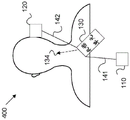
Fig. 1 is a schematic diagram of an example headset 100 for noise cancellation during uplink transmission. The headset 100 includes a right earphone 110, a left earphone 120, and a placket unit 130. It should be noted, however, that certain mechanisms disclosed herein may be employed in example headsets that include a single earpiece and/or examples without the flap unit 130. Headset 100 may be configured to perform local ANC, for example, when placket unit 130 is coupled to a device playing a music file. Headset 100 may also perform unlink noise cancellation, for example, when flap unit 130 is coupled to a device capable of making phone calls (e.g., a smartphone).
The right earpiece 110 is a device capable of playing audio data, such as music and/or speech from a remote caller. The right earpiece 110 may be made as a headset (headset), which may be positioned near the ear canal (e.g., on the ear) of the user. The right earpiece 110 may also be made as an earbud, in which case at least some portion of the right earpiece 110 may be positioned within the ear canal (e.g., within the ear) of the user. The right headphone 110 includes at least a speaker 115 and an FF microphone 111. The right earpiece 110 may also contain an FB microphone 113 and/or a sensor 117. Speaker 115 is any transducer capable of converting speech signals, audio signals, and/or ANC signals into sound waves for transmission to the ear canal of a user.
An ANC signal is an audio waveform that is generated to destructively interfere with a waveform carrying ambient noise, and thus cancel the noise from the perspective of the user. The ANC signal may be generated based on data recorded by the FF microphone 111 and/or the FB microphone 113. FB microphone 113 and speaker 115 are co-located on the adjacent wall of right earpiece 110. Depending on the example, the FB microphone 113 and the speaker 115 are positioned within the ear canal of the user when engaged (e.g., for an earbud) or positioned near the ear canal of the user in an acoustically sealed chamber when engaged (e.g., for an earpiece). The FB microphone 113 is configured to record sound waves entering the ear canal of the user. Accordingly, FB microphone 113 detects the user-perceived ambient noise, audio signals, remote speech signals, ANC signals, and/or the user's speech (which may be referred to as sideband signals). The FB microphone 113 signal may contain feedback information when the FB microphone 113 detects both the user-perceived ambient noise and any portion of the ANC signal that is not corrupted by destructive interference. The FB microphone 113 signal can be used to adjust the ANC signal to accommodate changing conditions and better cancel ambient noise.
Depending on the example, the FF microphone 111 is positioned on the distal wall of the earpiece and remains outside of the ear canal and/or acoustically sealed chamber of the user. When the right earphone is engaged, FF microphone 111 is acoustically isolated from the ANC signal, and typically from the remote speech signal and the audio signal. The FF microphone 111 records ambient noise as user speech/sidebands. Thus, the FF microphone 111 signal may be used to generate the ANC signal. The FF microphone 111 signal can better accommodate high frequency noise than the FB microphone 113 signal. However, FF microphone 111 cannot detect the results of the ANC signal and therefore cannot accommodate non-ideal conditions, such as poor acoustic sealing between right earpiece 110 and the ear. As such, FF microphone 111 and FB microphone 113 may be used in combination to generate an effective ANC signal.
The right earpiece 110 may also employ a sensing component to support off-ear detection (OED). For example, the signal processing for ANC assumes that the right earpiece 110 (and the left earpiece 230) are properly engaged. When a user removes one or more earphones, some ANC processing may not work as intended. Thus, headset 100 employs the sensing assembly to determine that the earpiece is not properly engaged. In some examples, FB microphone 113 and FF microphone 111 are employed as sensing components. In this case, when the right earpiece 110 is engaged, the FB microphone 113 signal and the FF microphone 111 signal are different due to acoustic isolation between the earpieces. When the FB microphone 113 signal and the FF microphone 111 signal are similar, the headset 100 may determine that the corresponding earphone 110 is not engaged. In other examples, the sensor 117 may be employed as a sensing component to support OED. For example, the sensor 117 may comprise an optical sensor that indicates a lower light level when the right earpiece 110 is engaged and a higher light level when the right earpiece 110 is not engaged. In other examples, the sensor 117 may employ pressure and/or electrical/magnetic currents and/or fields to determine when the right earpiece 110 is engaged or disengaged. In other words, the sensor 117 may include a capacitive sensor, an infrared sensor, a visible light optical sensor, or the like.
The left earpiece 120 is substantially similar to the right earpiece 110, but is configured to engage with the left ear of the user. Specifically, left earpiece 120 may contain sensor 127, speaker 125, FB microphone 123, and FF microphone 121, which may be substantially similar to sensor 117, speaker 115, FB microphone 113, and FF microphone 121. As described above, the left earphone 120 may also operate in substantially the same manner as the right earphone 110.
The left earphone 120 and the right earphone 110 may be coupled to the placket unit 130 via a left cable 142 and a right cable 141, respectively. Left cable 142 and right cable 141 are any cables capable of conducting audio signals, remote voice signals, and/or ANC signals from the lapel unit to left earphone 120 and right earphone 110, respectively.
In some examples, the placket unit 130 is an optional component. The placket unit 130 includes one or more voice microphones 131 and a signal processor 135. Voice microphone 131 may be any microphone configured to record a user's voice signals (e.g., during a telephone call) for uplink voice transmission. In some examples, multiple microphones may be employed to support beamforming techniques. Beamforming is a spatial signal processing technique that employs multiple receivers to record the same wave from multiple physical locations. The weighted average of the recordings can then be used as the recorded signal. By applying different weights to different microphones, the speech microphone 131 may be virtually pointed in a particular direction for increasing sound quality and/or filtering out ambient noise. It should be noted that the voice microphone 131 may be located in other locations as well in some examples. For example, the voice microphone 131 may be suspended from a cable 141 or 142 below the right earphone 110 or the left earphone 120, respectively. The beamforming techniques disclosed herein are equally applicable to such scenarios with slight geometric modifications.
The signal processor 135 is coupled to the left earphone 120 and the right earphone 110 via cables 142 and 141, and to the voice microphone 131. Signal processor 135 is any processor capable of generating ANC signals, performing digital and/or analog signal processing functions, and/or controlling the operation of headset 100. The signal processor 135 may contain and/or be connected to a memory and thus may be programmed for a particular function. The signal processor 135 may also be configured to convert analog signals to the digital domain for processing, and/or convert digital signals back to the analog domain for playback by the speakers 115 and 125. The signal processor 135 may be implemented as a general purpose processor and Application Specific Integrated Circuit (ASIC), a Digital Signal Processor (DSP), a Field Programmable Gate Array (FPGA), or a combination thereof.
The signal processor 135 may be configured to perform OED and VAD based on signals recorded by the sensors 117 and 127, the FB microphones 113 and 123, the FF microphones 111 and 121, and/or the voice microphone 131. In particular, the signal processor 135 employs various sensing components to determine the wearing position of the headset 100. In other words, the signal processor 135 may determine whether the right earphone 110 and the left earphone 120 are engaged or disengaged. Once the wearing position is determined, the signal processor 135 may select an appropriate signal model for the VAD and corresponding noise cancellation. A signal model may be selected from a plurality of signal models based on the determined wearing position. The signal processor 135 then applies the selected signal model to perform VAD and mitigate noise from the speech signal prior to uplink speech transmission.
For example, the signal processor 135 may perform OED by employing the FF microphones 111 and 121 and the FB microphones 113 and 123 as sensing components. The wearing position of the headset 100 can then be determined based on the difference between the FF microphones 111 and 121 signal and the FB microphones 113 and 123 signal, respectively. It should be noted that the difference includes subtraction as well as any other signal processing technique that compares signals, such as comparison of spectral ratios via a transfer function or the like. In other words, when the FF microphone 111 signal is substantially similar to the FB microphone 113 signal, the right earphone 110 is disengaged. When the FF microphone 111 signal is different from the FB microphone 113 signal (e.g., contains different waves at a particular frequency band), the right earphone 110 is engaged. The engagement or disengagement of the left earphone 120 can be determined in substantially the same manner by employing the FF microphone 121 and the FB microphone 123. In another example, the sensing component may include optical sensors 117 and 127. In this case, the wearing position of the headset is determined based on the light levels detected by the optical sensors 117 and 127.
Once the wearing position is determined by the OED processing performed by the signal processor 135, the signal processor may select an appropriate signal model for further processing. In some examples, the signal models include a left headphone engagement model, a right headphone engagement model, a dual headphone engagement model, and a no headphone engagement model. When the left earpiece 120 is engaged and the right earpiece 110 is not engaged, the left earpiece engagement model is employed. When the right earphone 110 is engaged and the left earphone 120 is not engaged, a right earphone engagement model is employed. When both earphones 110 and 120 are engaged, a dual earphone engagement model is employed. When both earphones 110 and 120 are disengaged, the no-earphone engagement model is used. The models are each explained in more detail with reference to the following figures.
Fig. 2 is a schematic diagram of an example dual earpiece junction model 200 for performing noise cancellation. When the OED process determines that both earpieces 110 and 120 are properly engaged, the dual earpiece engagement model 200 is employed. The result of this situation is the physical configuration shown. It should be noted that the illustrated components may not be drawn to scale. However, it should also be noted that this case leads to the following configuration: the flap unit 130 is suspended from the earphones 110 and 120 via cables 141 and 142, with the voice microphone 131 directed generally towards the user's mouth. Furthermore, the earpieces 110 and 120 are approximately equidistant from the user's mouth, which is located on a plane perpendicular to the plane between the earpieces 110 and 120. In such a configuration, multiple processes may be employed to detect and record the user's voice, and thus remove the ambient noise from such a recording.
In particular, the VAD may be derived from the headphones 110 and 120 by examining the cross-correlation between the audio signals received on the FF microphones 111 and 121 and using beamforming techniques. For example, the signal correlated between FF microphones 111 and 121 may originate from a general plane equidistant from both ears, and thus the signal may contain, or at least be in, the voice of the headset user. These waveforms originating at this location may be referred to as binaural VADs. In other words, the dual earpiece coupling model 200 may be applied to isolate noise signals from speech signals by correlating the left earpiece 120FF microphone 121 signal with the right earpiece 110FF microphone 111 signal when the left earpiece 120 and the right earpiece 110 are coupled.
As another example, the side-beam beamformer 112 may be created for local voice transmission enhancement, as the two ears are generally equidistant from the mouth. In other words, the dual headphone coupling model 200 can be applied to isolate noise signals from voice signals by employing the left headphone 120FF microphone 121 and the right headphone 110FF microphone 111 as the side-transmitting beamformer 112 when the left headphone 120 and the right headphone 120 are coupled. In particular, the side-transmitting beamformer 112 is any beamformer in which the measured waves (e.g., speech) are incident at the side on an array of measurement elements (e.g., FF microphones 111 and 121), so a phase difference of approximately 180 degrees is measured between the measurement elements. By appropriately weighting the signals from FF microphones 111 and 121, side-transmit beamformer 112 may isolate the speech signals from ambient noise that does not occur between the user's ears (e.g., noise from the user's left side or noise from the user's right side). Once the noise signal has been isolated, the ambient noise can be filtered out prior to uplink transmission to the remote user over the telephone call.
In summary, when the earphones 110 and 120 are well-fitted, the signals of the FB microphones 113 and 123 of the earphones 110 and 120 in-ear type and the FF microphones 111 and 121 of the external can be deconstructed into two signals, i.e., the local voice of the user and the ambient noise. Furthermore, the ambient noise is uncorrelated between the right earphone 110 and the left earphone 120. Accordingly, the OED algorithm operated by the signal processor 135 may allow the correlation between the right 110 and left 120 earphones, and the correlation between the FB microphones 113 and 123 and the FF microphones 111 and 121, to be used to recognize the local voice as VAD. Furthermore, the process, when run through a blind source separation algorithm, can provide a noise signal that is not contaminated by local speech.
The local speech estimate can be further refined using the input from the lapel unit 130 as a vertical end-beam beamformer 132. The endfire beamformer 132 is any beamformer in which the measured waves (e.g., speech) are directly incident on an array of measurement elements (e.g., speech microphones 131), so a small degree of phase difference (e.g., less than 10 degrees) is measured between the measurement elements. The end-fire beamformer 132 may be created by employing two or more voice microphones 131. The voice microphones 131 may then be weighted to virtually point the vertical end-fire beamformer 132 vertically towards the user's mouth, which is directly above the vertical end-fire beamformer 132 when both earpieces 110 and 120 are engaged. In other words, the voice microphone 131 may be located in the placket unit 130 connected to the left and right earphones 120 and 110. Therefore, when the dual earphone engagement model 200 is applied, the voice microphone 131 may be employed as the vertical end-beam former 132 to isolate the noise signal from the voice signal when the left earphone 120 and the right earphone 110 are engaged.
It should be noted that many of the above methods do not work properly when a single headset is not inserted into the ear, which may occur when a voice call is made while the user is trying to maintain awareness of the local environment. Therefore, it is desirable to detect when the earphones 110 and 120 are not well placed in the ears according to the OED. Accordingly, the OED mechanism may be used to improve binaural VAD, for example by time shifting error results when no headphones are engaged, and by turning off the side-transmit beamformer 112, as described below.
FIG. 3 is a schematic diagram of an exemplary right earphone engagement model 300 for performing noise cancellation. When the OED process determines that the right earphone 110 is engaged and the left earphone 120 is disengaged, the right earphone engagement model 300 is employed. The result of this is the physical configuration shown, which includes the left earphone 120 suspended from the placket unit 130 via a cable 142. As can be seen, the FF microphones 111 and 121 are no longer equidistant over the user's mouth. Therefore, any attempt to employ FF microphones 111 and 121 as side-transmitting beamformer 112 results in erroneous data. Such use may, for example, actually attenuate the speech signal and amplify the noise. Thus, the side-transmit beamformer 112 is turned off in the right earpiece engagement model 300.
Furthermore, the left earphone 120 is no longer engaged, so comparing FF microphone 121 and FB microphone 123 may also result in erroneous data because the microphones are no longer acoustically isolated. In other words, the signals of FF microphone 121 and FB microphone 123 are substantially similar in this configuration and no longer correctly distinguish between ambient noise and user speech. As such, the right earpiece engagement model 300 is applied to isolate the noise signal from the speech signal by employing the right earpiece 110FF microphone 111 and the right earpiece 110FB microphone 113 without regard to the left earpiece 120 microphone, with the right earpiece 110 engaged and the left earpiece 120 not engaged.
In addition, the placket unit 130 may be tilted to the left of the straight vertical configuration when suspended from the engaged right earphone 110 via the cable 141. As such, the beamformer can be adjusted to point to the user's mouth in order to support accurate voice isolation. When adjusted in this manner, the beamformer may be referred to as a right direction (directional) end-fire beamformer 133, where the right direction indicates an offset to the right of the vertical beamformer 132. The right directional end-fire beamformer 133 may be created by adjusting the weights of the voice microphones 131 to emphasize the voice signals recorded by the rightmost voice microphone 131. Thus, the right earpiece engagement model 300 can be applied to isolate noise signals from voice signals by employing the voice microphone 131 as the right-direction end-fire beamformer 133 when the right earpiece 110 is engaged and the left earpiece 120 is not engaged.
Fig. 4 is a schematic diagram of an exemplary left headphone engagement model 400 for performing noise cancellation. When the OED process determines that the left earphone 120 is engaged and the right earphone 110 is disengaged, the left earphone engagement model 400 is employed. The result of this is that the right earphone 110 is suspended from the placket unit 130 via the cable 110, and the placket unit 130 is suspended from the left earphone 120 via the cable 142. The left headphone engagement model 400 is substantially similar to the right headphone engagement model 300 with the process reversed in all directions. In other words, the side-transmit beamformer 112 is turned off. Furthermore, the left earpiece junction model 400 is applied by employing the left earpiece 120FF microphone 121 and the left earpiece 120FB microphone 123 to isolate the noise signal from the speech signal. However, when the left earphone 120 is engaged and the right earphone 110 is not engaged, the right earphone 110 microphone is not considered.
In addition, in the left earphone engagement model 400, the lappet unit 130 voice microphone 131 is directed to the right of the vertical position. As such, the beamformer can be adjusted to point to the user's mouth in order to support accurate voice isolation. When adjusted in this manner, the beamformer may be referred to as a left direction end-fire beamformer 134, where the left direction indicates an offset to the left of the vertical beamformer 132. The left side end-fire beamformer 134 may be created by adjusting the weights of the voice microphones 131 to emphasize the voice signals recorded by the leftmost voice microphone 131. Thus, by employing the speech microphone 131 as the left-side end-fire beamformer 134 when the left earphone 120 is engaged and the right earphone 110 is not engaged, the left earphone engagement model 400 is applied to isolate the noise signal from the speech signal.
Fig. 5 is a schematic diagram of an example headphone-less engagement model 500 for performing noise cancellation. In the no-engagement model 500, neither of the earphones 110 and 120 are properly engaged. In such a case, any attempt to perform ANC may potentially result in attenuating speech and/or amplifying noise. Thus, the headphone-less engagement model 500 is applied to mitigate additive noise (added noise) by interrupting beamformer use when both left headphone 120 and right headphone 110 are disengaged. In addition, the correlation of FB microphones 113 and 123 with FF microphones 111 and 121 may also be interrupted to mitigate the possibility of attenuating speech and/or amplifying noise.
In summary, the signal processor 135 may employ the signal processing models 200, 300, 400, and/or 500 based on the wearing position to support mitigating ambient noise in the recorded voice signal prior to uplink transmission during the phone call. These subsystems may be implemented in separate modules within the signal processor, such as a VAD module and an OED module. These modules may operate in series to improve the accuracy of speech detection and noise mitigation. For example, as described above, VAD derived from the headset 110 and 120 microphones may be used to improve transmission noise reduction. This can be done in a number of ways. VAD may be employed as a guide to accommodate beamforming in the microphone boom/array. The adaptive beamformer may determine the final beam direction by analyzing the recorded sounds for the voice-like signals. It should be noted that the problem of voice detection from a microphone is not trivial and may suffer from false negatives and false positives. Improved VAD (e.g., identifying when a headset 100 user is speaking) improves adaptive beamformer performance by increasing directional accuracy. In addition, a VAD may be employed as an input to the smart mute process that reduces the transmit signal to zero when the user of headset 100 is not speaking. VADs may also be employed as inputs to the continuously adaptive ANC system. In a continuous adaptive ANC system, the FB microphone signal can be considered to be the downlink-only signal, and thus mostly free of noise. The FB microphone, when engaged, may also record a component of the local conversation from the user, which may be removed when signal processor 135 determines that the user of headset 100 is speaking. Additionally, it is generally observed that FF adaptation is less accurate when a headset 100 user speaks during adaptation. Therefore, when a user speaks, the VAD can be employed to freeze the adaptation.
The OED module may serve as a mechanism to ignore the output of information derived from the headset. OED detection can be performed by various mechanisms, such as comparing FF and FB signal levels, without affecting the utility of the information. When determining the OED of the headset, the correlation between the headset microphones is used to obtain a local voice estimate for noise reduction or VAD (e.g., via beamforming, correlation of left and right FF signals, blind source separation, or other mechanisms). As such, OED becomes the input to VAD and any algorithms that use FF and/or FB microphone signals. As described above, if any of the earphones is detached, it is not effective to perform beamforming using the FF microphone.
Fig. 6 is a flow diagram of an example method 600 for performing noise cancellation during uplink transmission, e.g., by employing headset 100 to process signals according to models 200, 300, 400, and/or 500. In some examples, the method 600 may be implemented as a computer program product stored in memory and executed by the signal processor 135 and/or any other hardware, firmware, or other processing system disclosed herein.
At block 601, sensing components of headset 100, such as FB microphones 113 and 123, FF microphones 111 and 121, sensors 117 and 127, and/or voice microphone 131, are employed to determine a wearing position of the headset. The wearing position may be determined by any mechanism disclosed herein, such as by correlating recorded audio signals, considering optical and/or pressure sensors, etc. Once the wearing position is determined from the OED, a signal model is selected for noise cancellation at block 603. A signal model may be selected from a plurality of signal models based on the determined wearing position. As described above, the plurality of models may include the left earphone engagement model 400, the right earphone engagement model 300, the dual earphone engagement model 200, and the no earphone engagement model 500.
At block 605, voice signals are recorded at one or more voice microphones (such as voice microphone 131) connected to the headset. Further, at block 607, the selected model is applied to mitigate noise from the speech signal prior to transmission of the speech. It should be noted that block 607 may be applied after block 605 and/or in conjunction with block 605. As described above, applying the dual earphone engagement model may include: when the left and right earphones are joined, the left and right earphone FF microphones are employed as a side-fire beamformer to isolate the noise signal from the speech signal. In addition, applying the dual earphone engagement model may further include: when the left and right earphones are joined, a voice microphone is employed as a vertical end-fire beamformer to isolate the noise signal from the voice signal. In some examples, applying the dual earpiece engagement model may further comprise: when the left and right earphones are engaged, the left earphone feed-forward (FF) microphone signal and the right earphone FF microphone signal are correlated to isolate the noise signal from the speech signal. Moreover, applying the earless engagement model at block 607 includes: when both the left and right earphones are disengaged, the beamformer usage is interrupted to mitigate additive noise.
Further, applying the right headphone engagement model at block 607 includes: the right headset FF microphone and the right headset FB microphone are employed without regard to the left headset microphone when the right headset is engaged and the left headset is not engaged to isolate the noise signal from the speech signal. Applying the right earphone engagement model at block 607 may also include: when the right earphone is engaged and the left earphone is not engaged, the voice microphone is employed as a right directional end-fire beamformer for isolating noise signals from voice signals.
Additionally, applying the left headphone engagement model at block 607 includes: when the left earphone is engaged and the right earphone is not engaged, the left earphone FF microphone and the left earphone FB microphone are employed without regard to the right earphone microphone to isolate the noise signal from the voice signal. Finally, applying the left earpiece engagement model at block 607 may also include: when the left earphone is engaged and the right earphone is not engaged, the voice microphone is employed as a left side port-fire beamformer for isolating noise signals from voice signals.
Examples of the disclosure may operate on specially constructed hardware, firmware, digital signal processors, or on a specially programmed general purpose computer including a processor operating according to programmed instructions. The term "controller" or "processor" as used herein is intended to encompass microprocessors, microcomputers, application Specific Integrated Circuits (ASICs), and dedicated hardware controllers. One or more aspects of the present disclosure can be embodied in computer-usable data and computer-executable instructions (e.g., a computer program product) executed by one or more processors (including a monitoring module) or other devices, such as in one or more program modules. Generally, program modules include routines, programs, objects, components, data structures, etc. that perform particular tasks or implement particular abstract data types when executed by a processor in a computer or other device. Computer-executable instructions may be stored on non-transitory computer-readable media, such as Random Access Memory (RAM), read Only Memory (ROM), cache, electrically Erasable Programmable Read Only Memory (EEPROM), flash memory or other memory technologies, as well as any other volatile or non-volatile, removable or non-removable media implemented in any technology. The computer readable medium excludes the signal itself and transitory forms of signal transmission. In addition, the functions may be embodied in whole or in part in firmware or hardware equivalents such as integrated circuits, field Programmable Gate Arrays (FPGAs), and the like. Particular data structures may be used to more effectively implement one or more aspects of the present disclosure, and such data structures are contemplated within the scope of computer-executable instructions and computer-usable data described herein.
Aspects of the present disclosure operate in various modifications and alternative forms. Certain aspects have been shown by way of example in the drawings and will be described in detail below. It should be noted, however, that the examples disclosed herein are presented for clarity of discussion, and are not intended to limit the scope of the general concepts disclosed to the particular examples described herein, unless explicitly defined. As such, the disclosure is intended to cover all modifications, equivalents, and alternatives to the described aspects in light of the drawings and the claims.
References in the specification to embodiments, aspects, examples, etc., indicate that the item described may include a particular feature, structure, or characteristic. However, each disclosed aspect may or may not include the particular feature, structure, or characteristic. Moreover, the phrases are not necessarily referring to the same aspect unless specifically stated otherwise. Further, when a particular feature, structure, or characteristic is described in connection with a particular aspect, such feature, structure, or characteristic may be employed in connection with other disclosed aspects whether or not such feature, structure, or characteristic is explicitly described in connection with such other disclosed aspects.
Examples of the invention
Illustrative examples of the techniques disclosed herein are provided below. Embodiments of these techniques may include any one or more of the following examples and any combination thereof.
Example 1 comprises a headset comprising: one or more earphones comprising one or more sensing components; one or more voice microphones to record voice signals for voice transmission; and a signal processor coupled to the headset and the voice microphone, the signal processor configured to: the method includes determining a wearing position of the headset using the sensing assembly, selecting a signal model for noise cancellation, the signal model selected from a plurality of signal models based on the determined wearing position, and applying the selected signal model to mitigate noise from the voice signal prior to voice transmission.
Example 2 includes the headset of example 1, wherein the sensing component includes a feed-forward (FF) microphone and a Feedback (FB) microphone, the wearing position of the headset being determined based on a difference between the FF microphone signal and the FB microphone signal.
Example 3 includes the headset of any of examples 1-2, wherein the sensing assembly includes an optical sensor, a capacitive sensor, an infrared sensor, or a combination thereof.
Example 4 includes the headset of any of examples 1-3, wherein the one or more earpieces include a left earpiece and a right earpiece, and the plurality of signal models include a left earpiece engagement model, a right earpiece engagement model, a dual earpiece engagement model, and a no earpiece engagement model.
Example 5 includes the headset of any of examples 1-4, wherein the dual earpiece junction model is applied to isolate noise signals from voice signals by employing a left earpiece feed-forward (FF) microphone and a right earpiece FF microphone as side-fire beamformers when the left and right earpieces are joined.
Example 6 includes the headset of any of examples 1-5, wherein the voice microphone is located in a lapel unit connected to the left and right earpieces, and the dual earpiece junction model is applied to isolate the noise signal from the voice signal by employing the voice microphone as a vertical end-fire beamformer when the left and right earpieces are joined.
Example 7 includes the headset of any of examples 1-6, wherein the dual earpiece engagement model is applied to isolate the noise signal from the speech signal by correlating a left earpiece feed-forward (FF) microphone signal with a right earpiece FF microphone signal when the left earpiece and the right earpiece are engaged.
Example 8 includes the headset of any of examples 1-7, wherein the no-earpiece engagement model is applied to mitigate additive noise by interrupting beamformer use when both the left earpiece and the right earpiece are disengaged.
Example 9 includes the headset of any of examples 1-8, wherein the left earpiece engagement model is applied to isolate the noise signal from the speech signal by employing a left earpiece feed-forward (FF) microphone and a left earpiece Feedback (FB) microphone, without regard to the right earpiece microphone, when the left earpiece is engaged and the right earpiece is not engaged.
Example 10 includes the headset of any of examples 1-9, wherein the voice microphone is located in a lapel unit connected to the left and right earpieces, and the left earpiece engagement model is applied to isolate the noise signal from the voice signal by employing the voice microphone as a left directional end-fire beamformer when the left earpiece is engaged and the right earpiece is not engaged.
Example 11 includes the headset of any of examples 1-10, wherein the right earpiece engagement model is applied to isolate the noise signal from the speech signal by employing a right earpiece feed-forward (FF) microphone and a right earpiece Feedback (FB) microphone without regard to the left earpiece microphone when the right earpiece is engaged and the left earpiece is not engaged.
Example 12 includes the headset of any of examples 1-11, wherein the voice microphone is located in a lapel unit connected to the left and right earpieces, and the right earpiece engagement model is applied to isolate the noise signal from the voice signal by employing the voice microphone as a right directional end-fire beamformer when the right earpiece is engaged and the left earpiece is not engaged.
Example 13 includes a method comprising: determining a wearing position of the headset by using a sensing component of the headset; selecting a signal model for noise cancellation, the signal model being selected from a plurality of signal models based on the determined wearing position; recording voice signals at one or more voice microphones connected to the headset; and applying the selected signal model to mitigate noise from the speech signal prior to transmission of the speech.
Example 14 includes the method of example 13, wherein the headset includes left and right earpieces, and the plurality of signal models includes a left earpiece engagement model, a right earpiece engagement model, a dual earpiece engagement model, and a no earpiece engagement model.
Example 15 includes the method of any one of examples 13-14, wherein applying the dual earpiece junction model includes: when the left and right earphones are joined, a left earphone feed-forward (FF) microphone and a right earphone FF microphone are employed as side-transmitting beamformers to isolate noise signals from speech signals.
Example 16 includes the method of any of examples 13-15, wherein the voice microphone is located in a placket unit connected to a left earpiece and a right earpiece, and applying the dual earpiece junction model includes: when the left and right earphones are joined, a voice microphone is employed as a vertical end-fire beamformer to isolate the noise signal from the voice signal.
Example 17 includes the method of any one of examples 13-16, wherein applying the dual earpiece junction model includes: when the left and right earphones are engaged, the left earphone feed-forward (FF) microphone signal is correlated with the right earphone FF microphone signal to isolate the noise signal from the speech signal.
Example 18 includes the method of any one of examples 13-17, wherein applying the headphone-less engagement model includes: beamformer use is discontinued when both the left and right earpieces are disengaged to mitigate additive noise.
Example 19 includes the method of any one of examples 13-18, wherein applying the right earpiece engagement model includes: a right headphone feed-forward (FF) microphone and a right headphone Feedback (FB) microphone are employed when the right headphone is engaged and the left headphone is not engaged, regardless of the left headphone microphone, to isolate the noise signal from the speech signal.
Example 20 includes the method of any one of examples 13-19, wherein the voice microphone is located in a placket unit connected to a left earpiece and a right earpiece, and applying the left earpiece junction model includes: when the left earphone is engaged and the right earphone is not engaged, the voice microphone is used as the left endfire beamformer to isolate the noise signal from the voice signal.
Example 21 includes a computer program product that, when executed on a signal processor, causes the headset to perform the method according to any of examples 13-20.
The previously described examples of the disclosed subject matter have many advantages that are either described or are apparent to one of ordinary skill. Even so, not all of these advantages or features are required in all versions of the disclosed apparatus, systems, or methods.
In addition, this written description makes reference to specific features. It is to be understood that the disclosure in this specification includes all possible combinations of those specific features. Where a particular feature is disclosed in the context of a particular aspect or example, it may also be used, to the extent possible, in the context of other aspects and examples.
Further, when a method having two or more defined steps or operations is referred to in this application, the defined steps or operations may be performed in any order or simultaneously, unless the context excludes those possibilities.
While specific examples of the disclosure have been illustrated and described for purposes of illustration, it will be understood that various modifications may be made without departing from the spirit and scope of the disclosure. Accordingly, the disclosure should not be limited except by the appended claims.
Claims (12)
1. A headset, comprising:
a headset comprising one or more sensing components, the headset comprising a first headset having a feedforward microphone and a feedback microphone and a second headset having a feedforward microphone and a feedback microphone;
one or more voice microphones to record voice signals for voice transmission; and
a signal processor coupled to the headset and the voice microphone, the signal processor configured to:
determining a wearing position of the headset with the sensing assembly, the wearing position of the headset including a single earpiece engagement and a dual earpiece engagement,
selecting a signal model from a plurality of signal models based on the determined wearing position, the plurality of signal models including a single earphone engagement model and a dual earphone engagement model,
when the selected signal model is a two-earphone junction model, employing a feedforward microphone of the first earphone and a feedforward microphone of the second earphone as side-emitting beamformers to isolate noise signals from speech signals, and
when the selected signal model is a single earpiece junction model, the side-fire beamformer is deactivated, the one or more speech microphones are employed as the first directional end-fire beamformer, and the first feed-forward microphone and the first feedback microphone, without regard to the second feed-forward microphone and the second feedback microphone, are employed to isolate the noise signal from the speech signal.
2. The headset of claim 1, wherein the sensing component includes a feedforward microphone and a feedback microphone for each of the first and second earpieces, the wearing position of the headset determined based on a difference between a feedforward microphone signal and a feedback microphone signal.
3. The headset of claim 1 wherein the sensing component includes an optical sensor, a capacitive sensor, an infrared sensor, or combinations thereof.
4. The headset of claim 1, wherein the plurality of signal models further includes a no-earpiece engagement model.
5. A headset according to claim 1 wherein the voice microphone is located in a lappet unit connected to the first and second earpieces and the dual earpiece junction model is applied to isolate noise signals from the voice signals by employing the voice microphone as a vertical end-fire beamformer when the first and second earpieces are joined.
6. A headset according to claim 1 wherein the dual earpiece engagement model is applied by correlating a first earpiece feedforward microphone signal with a right earpiece feedforward microphone signal when the left and right earpieces are engaged to isolate a noise signal from the speech signal.
7. The headset of claim 4, wherein the no-earpiece engagement model is applied to mitigate additive noise by interrupting beamformer use when both the first earpiece and the second earpiece are disengaged.
8. A headset according to claim 1 wherein the voice microphone is located in a lapel unit connected to left and right ear pieces.
9. A method of noise cancellation, comprising:
determining a wearing position of a headset with a sensing component of the headset, the wearing position of the headset including a single earpiece engagement and a dual earpiece engagement;
selecting a signal model for noise cancellation, the signal model selected from a plurality of signal models including a single earphone engagement model and a dual earphone engagement model based on the determined wearing position;
when the selected signal model is a dual-earpiece junction model, employing a feedforward microphone of the first earpiece and a feedforward microphone of the second earpiece as side-beam beamformers to detect and isolate speech signals from noise signals and to record the speech signals at one or more speech microphones, and
when the selected signal model is a single earphone engagement model, the side-fire beamformer is deactivated, one or more speech microphones are employed as the first directional end-fire beamformer, and a feed-forward microphone of the first earphone and a feedback microphone of the first earphone are employed without regard to a second feed-forward microphone of the second earphone and a feedback microphone of the second earphone to detect speech signals and isolate noise signals from the speech signals.
10. The method of claim 9, wherein the plurality of signal models further includes a headphone-less engagement model.
11. The method of claim 10, wherein the voice microphone is located in a placket unit connected to a first earphone and a second earphone.
12. The method of claim 10, wherein applying the headphone-less engagement model comprises: the beamformer use is discontinued when both the first and second earpieces are disengaged to mitigate additive noise.
Applications Claiming Priority (3)
| Application Number | Priority Date | Filing Date | Title |
|---|---|---|---|
| US201662412214P | 2016-10-24 | 2016-10-24 | |
| US62/412,214 | 2016-10-24 | ||
| PCT/US2017/058129 WO2018081155A1 (en) | 2016-10-24 | 2017-10-24 | Automatic noise cancellation using multiple microphones |
Publications (2)
| Publication Number | Publication Date |
|---|---|
| CN110392912A CN110392912A (en) | 2019-10-29 |
| CN110392912B true CN110392912B (en) | 2022-12-23 |
Family
ID=60269958
Family Applications (1)
| Application Number | Title | Priority Date | Filing Date |
|---|---|---|---|
| CN201780080113.9A Active CN110392912B (en) | 2016-10-24 | 2017-10-24 | Automatic noise cancellation using multiple microphones |
Country Status (7)
| Country | Link |
|---|---|
| US (2) | US10354639B2 (en) |
| EP (1) | EP3529801B1 (en) |
| JP (1) | JP7252127B2 (en) |
| KR (2) | KR102472574B1 (en) |
| CN (1) | CN110392912B (en) |
| TW (2) | TWI823334B (en) |
| WO (1) | WO2018081155A1 (en) |
Families Citing this family (24)
| Publication number | Priority date | Publication date | Assignee | Title |
|---|---|---|---|---|
| US11102567B2 (en) | 2016-09-23 | 2021-08-24 | Apple Inc. | Foldable headphones |
| KR102535726B1 (en) * | 2016-11-30 | 2023-05-24 | 삼성전자주식회사 | Method for detecting earphone position, storage medium and electronic device therefor |
| JP6874430B2 (en) * | 2017-03-09 | 2021-05-19 | ティアック株式会社 | Voice recorder |
| US11494473B2 (en) * | 2017-05-19 | 2022-11-08 | Plantronics, Inc. | Headset for acoustic authentication of a user |
| EP3734989B1 (en) | 2017-11-20 | 2023-07-05 | Apple Inc. | Headphones |
| WO2019151045A1 (en) * | 2018-01-30 | 2019-08-08 | Jfeスチール株式会社 | Steel material for line pipes, production method for same, and production method for line pipe |
| CN111869233B (en) | 2018-04-02 | 2023-04-14 | 苹果公司 | Earphone set |
| CN109195043B (en) * | 2018-07-16 | 2020-11-20 | 恒玄科技(上海)股份有限公司 | Method for improving noise reduction amount of wireless double-Bluetooth headset |
| GB2575815B (en) * | 2018-07-23 | 2020-12-09 | Dyson Technology Ltd | A wearable air purifier |
| CN110891226B (en) * | 2018-09-07 | 2022-06-24 | 中兴通讯股份有限公司 | Denoising method, denoising device, denoising equipment and storage medium |
| US10681452B1 (en) | 2019-02-26 | 2020-06-09 | Qualcomm Incorporated | Seamless listen-through for a wearable device |
| CN110300344A (en) * | 2019-03-25 | 2019-10-01 | 深圳市增长点科技有限公司 | Adaptive noise reduction earphone |
| CN111800722B (en) * | 2019-04-28 | 2021-07-20 | 深圳市豪恩声学股份有限公司 | Feedforward microphone function detection method and device, terminal equipment and storage medium |
| US11172298B2 (en) | 2019-07-08 | 2021-11-09 | Apple Inc. | Systems, methods, and user interfaces for headphone fit adjustment and audio output control |
| US11043201B2 (en) * | 2019-09-13 | 2021-06-22 | Bose Corporation | Synchronization of instability mitigation in audio devices |
| CN111800687B (en) * | 2020-03-24 | 2022-04-12 | 深圳市豪恩声学股份有限公司 | Active noise reduction method and device, electronic equipment and storage medium |
| US11722178B2 (en) | 2020-06-01 | 2023-08-08 | Apple Inc. | Systems, methods, and graphical user interfaces for automatic audio routing |
| US11375314B2 (en) | 2020-07-20 | 2022-06-28 | Apple Inc. | Systems, methods, and graphical user interfaces for selecting audio output modes of wearable audio output devices |
| US11941319B2 (en) | 2020-07-20 | 2024-03-26 | Apple Inc. | Systems, methods, and graphical user interfaces for selecting audio output modes of wearable audio output devices |
| CN113973249B (en) * | 2020-07-24 | 2023-04-07 | 华为技术有限公司 | Earphone communication method and earphone |
| US11122350B1 (en) * | 2020-08-18 | 2021-09-14 | Cirrus Logic, Inc. | Method and apparatus for on ear detect |
| US11523243B2 (en) | 2020-09-25 | 2022-12-06 | Apple Inc. | Systems, methods, and graphical user interfaces for using spatialized audio during communication sessions |
| CN112242148B (en) * | 2020-11-12 | 2023-06-16 | 北京声加科技有限公司 | Headset-based wind noise suppression method and device |
| US11875811B2 (en) * | 2021-12-09 | 2024-01-16 | Lenovo (United States) Inc. | Input device activation noise suppression |
Citations (6)
| Publication number | Priority date | Publication date | Assignee | Title |
|---|---|---|---|---|
| CN101031956A (en) * | 2004-07-22 | 2007-09-05 | 索福特迈克斯有限公司 | Headset for separation of speech signals in a noisy environment |
| US20110222701A1 (en) * | 2009-09-18 | 2011-09-15 | Aliphcom | Multi-Modal Audio System With Automatic Usage Mode Detection and Configuration Capability |
| CN102300140A (en) * | 2011-08-10 | 2011-12-28 | 歌尔声学股份有限公司 | Speech enhancing method and device of communication earphone and noise reduction communication earphone |
| US20130182867A1 (en) * | 2012-01-12 | 2013-07-18 | Plantronics, Inc. | Wearing Position Derived Device Operation |
| WO2014055312A1 (en) * | 2012-10-02 | 2014-04-10 | Mh Acoustics, Llc | Earphones having configurable microphone arrays |
| US20140307890A1 (en) * | 2013-04-16 | 2014-10-16 | Cirrus Logic, Inc. | Systems and methods for adaptive noise cancellation including secondary path estimate monitoring |
Family Cites Families (14)
| Publication number | Priority date | Publication date | Assignee | Title |
|---|---|---|---|---|
| US8818000B2 (en) | 2008-04-25 | 2014-08-26 | Andrea Electronics Corporation | System, device, and method utilizing an integrated stereo array microphone |
| US8243946B2 (en) * | 2009-03-30 | 2012-08-14 | Bose Corporation | Personal acoustic device position determination |
| US20140294193A1 (en) * | 2011-02-25 | 2014-10-02 | Nokia Corporation | Transducer apparatus with in-ear microphone |
| JP6069829B2 (en) * | 2011-12-08 | 2017-02-01 | ソニー株式会社 | Ear hole mounting type sound collecting device, signal processing device, and sound collecting method |
| US9344792B2 (en) | 2012-11-29 | 2016-05-17 | Apple Inc. | Ear presence detection in noise cancelling earphones |
| EP2819429B1 (en) * | 2013-06-28 | 2016-06-22 | GN Netcom A/S | A headset having a microphone |
| US9190043B2 (en) * | 2013-08-27 | 2015-11-17 | Bose Corporation | Assisting conversation in noisy environments |
| US9386391B2 (en) * | 2014-08-14 | 2016-07-05 | Nxp B.V. | Switching between binaural and monaural modes |
| EP3057337B1 (en) * | 2015-02-13 | 2020-03-25 | Oticon A/s | A hearing system comprising a separate microphone unit for picking up a users own voice |
| US9905216B2 (en) | 2015-03-13 | 2018-02-27 | Bose Corporation | Voice sensing using multiple microphones |
| US9401158B1 (en) * | 2015-09-14 | 2016-07-26 | Knowles Electronics, Llc | Microphone signal fusion |
| US9967682B2 (en) * | 2016-01-05 | 2018-05-08 | Bose Corporation | Binaural hearing assistance operation |
| CN105848054B (en) * | 2016-03-15 | 2020-04-10 | 歌尔股份有限公司 | Earphone and noise reduction method thereof |
| KR102535726B1 (en) * | 2016-11-30 | 2023-05-24 | 삼성전자주식회사 | Method for detecting earphone position, storage medium and electronic device therefor |
-
2017
- 2017-10-24 TW TW111113769A patent/TWI823334B/en active
- 2017-10-24 KR KR1020197014854A patent/KR102472574B1/en active IP Right Grant
- 2017-10-24 US US15/792,378 patent/US10354639B2/en active Active
- 2017-10-24 EP EP17795145.6A patent/EP3529801B1/en active Active
- 2017-10-24 TW TW106136588A patent/TWI763727B/en active
- 2017-10-24 CN CN201780080113.9A patent/CN110392912B/en active Active
- 2017-10-24 JP JP2019543191A patent/JP7252127B2/en active Active
- 2017-10-24 KR KR1020227041531A patent/KR102508844B1/en active IP Right Grant
- 2017-10-24 WO PCT/US2017/058129 patent/WO2018081155A1/en unknown
-
2019
- 2019-06-19 US US16/446,064 patent/US11056093B2/en active Active
Patent Citations (6)
| Publication number | Priority date | Publication date | Assignee | Title |
|---|---|---|---|---|
| CN101031956A (en) * | 2004-07-22 | 2007-09-05 | 索福特迈克斯有限公司 | Headset for separation of speech signals in a noisy environment |
| US20110222701A1 (en) * | 2009-09-18 | 2011-09-15 | Aliphcom | Multi-Modal Audio System With Automatic Usage Mode Detection and Configuration Capability |
| CN102300140A (en) * | 2011-08-10 | 2011-12-28 | 歌尔声学股份有限公司 | Speech enhancing method and device of communication earphone and noise reduction communication earphone |
| US20130182867A1 (en) * | 2012-01-12 | 2013-07-18 | Plantronics, Inc. | Wearing Position Derived Device Operation |
| WO2014055312A1 (en) * | 2012-10-02 | 2014-04-10 | Mh Acoustics, Llc | Earphones having configurable microphone arrays |
| US20140307890A1 (en) * | 2013-04-16 | 2014-10-16 | Cirrus Logic, Inc. | Systems and methods for adaptive noise cancellation including secondary path estimate monitoring |
Also Published As
| Publication number | Publication date |
|---|---|
| TW201820892A (en) | 2018-06-01 |
| EP3529801A1 (en) | 2019-08-28 |
| JP7252127B2 (en) | 2023-04-04 |
| KR102472574B1 (en) | 2022-12-02 |
| US11056093B2 (en) | 2021-07-06 |
| TWI763727B (en) | 2022-05-11 |
| KR102508844B1 (en) | 2023-03-13 |
| WO2018081155A1 (en) | 2018-05-03 |
| TWI823334B (en) | 2023-11-21 |
| US20180114518A1 (en) | 2018-04-26 |
| TW202232969A (en) | 2022-08-16 |
| US20190304430A1 (en) | 2019-10-03 |
| JP2019537398A (en) | 2019-12-19 |
| EP3529801B1 (en) | 2020-12-23 |
| CN110392912A (en) | 2019-10-29 |
| KR20190087438A (en) | 2019-07-24 |
| KR20220162187A (en) | 2022-12-07 |
| US10354639B2 (en) | 2019-07-16 |
Similar Documents
| Publication | Publication Date | Title |
|---|---|---|
| CN110392912B (en) | Automatic noise cancellation using multiple microphones | |
| US10319392B2 (en) | Headset having a microphone | |
| EP2680608B1 (en) | Communication headset speech enhancement method and device, and noise reduction communication headset | |
| US11614916B2 (en) | User voice activity detection | |
| US11373665B2 (en) | Voice isolation system | |
| US11330358B2 (en) | Wearable audio device with inner microphone adaptive noise reduction | |
| KR20090050372A (en) | Noise cancelling method and apparatus from the mixed sound | |
| WO2015010722A1 (en) | Headphone, earphone and headset | |
| JP2020506634A (en) | Method for detecting user voice activity in a communication assembly, the communication assembly | |
| EP2830324B1 (en) | Headphone and headset | |
| CN115735362A (en) | Voice activity detection | |
| EP3840402B1 (en) | Wearable electronic device with low frequency noise reduction | |
| CN114450745A (en) | Audio system and signal processing method for ear-wearing type playing device | |
| US11533555B1 (en) | Wearable audio device with enhanced voice pick-up |
Legal Events
| Date | Code | Title | Description |
|---|---|---|---|
| PB01 | Publication | ||
| PB01 | Publication | ||
| SE01 | Entry into force of request for substantive examination | ||
| SE01 | Entry into force of request for substantive examination | ||
| REG | Reference to a national code |
Ref country code: HK Ref legal event code: DE Ref document number: 40011657 Country of ref document: HK |
|
| GR01 | Patent grant | ||
| GR01 | Patent grant |