CN110383739B - Method and apparatus for transmitting and receiving physical uplink control channel between terminal and base station in wireless communication system - Google Patents
Method and apparatus for transmitting and receiving physical uplink control channel between terminal and base station in wireless communication system Download PDFInfo
- Publication number
- CN110383739B CN110383739B CN201880015591.6A CN201880015591A CN110383739B CN 110383739 B CN110383739 B CN 110383739B CN 201880015591 A CN201880015591 A CN 201880015591A CN 110383739 B CN110383739 B CN 110383739B
- Authority
- CN
- China
- Prior art keywords
- symbol
- pucch
- uci
- frequency hopping
- symbols
- Prior art date
- Legal status (The legal status is an assumption and is not a legal conclusion. Google has not performed a legal analysis and makes no representation as to the accuracy of the status listed.)
- Active
Links
Images


Classifications
-
- H—ELECTRICITY
- H04—ELECTRIC COMMUNICATION TECHNIQUE
- H04B—TRANSMISSION
- H04B1/00—Details of transmission systems, not covered by a single one of groups H04B3/00 - H04B13/00; Details of transmission systems not characterised by the medium used for transmission
- H04B1/69—Spread spectrum techniques
- H04B1/713—Spread spectrum techniques using frequency hopping
-
- H—ELECTRICITY
- H04—ELECTRIC COMMUNICATION TECHNIQUE
- H04L—TRANSMISSION OF DIGITAL INFORMATION, e.g. TELEGRAPHIC COMMUNICATION
- H04L5/00—Arrangements affording multiple use of the transmission path
- H04L5/0001—Arrangements for dividing the transmission path
- H04L5/0003—Two-dimensional division
- H04L5/0005—Time-frequency
- H04L5/0007—Time-frequency the frequencies being orthogonal, e.g. OFDM(A), DMT
- H04L5/0012—Hopping in multicarrier systems
-
- H—ELECTRICITY
- H04—ELECTRIC COMMUNICATION TECHNIQUE
- H04L—TRANSMISSION OF DIGITAL INFORMATION, e.g. TELEGRAPHIC COMMUNICATION
- H04L5/00—Arrangements affording multiple use of the transmission path
-
- H—ELECTRICITY
- H04—ELECTRIC COMMUNICATION TECHNIQUE
- H04L—TRANSMISSION OF DIGITAL INFORMATION, e.g. TELEGRAPHIC COMMUNICATION
- H04L5/00—Arrangements affording multiple use of the transmission path
- H04L5/003—Arrangements for allocating sub-channels of the transmission path
- H04L5/0048—Allocation of pilot signals, i.e. of signals known to the receiver
- H04L5/0051—Allocation of pilot signals, i.e. of signals known to the receiver of dedicated pilots, i.e. pilots destined for a single user or terminal
-
- H—ELECTRICITY
- H04—ELECTRIC COMMUNICATION TECHNIQUE
- H04L—TRANSMISSION OF DIGITAL INFORMATION, e.g. TELEGRAPHIC COMMUNICATION
- H04L5/00—Arrangements affording multiple use of the transmission path
- H04L5/003—Arrangements for allocating sub-channels of the transmission path
- H04L5/0053—Allocation of signaling, i.e. of overhead other than pilot signals
-
- H—ELECTRICITY
- H04—ELECTRIC COMMUNICATION TECHNIQUE
- H04L—TRANSMISSION OF DIGITAL INFORMATION, e.g. TELEGRAPHIC COMMUNICATION
- H04L5/00—Arrangements affording multiple use of the transmission path
- H04L5/0091—Signaling for the administration of the divided path
- H04L5/0094—Indication of how sub-channels of the path are allocated
-
- H—ELECTRICITY
- H04—ELECTRIC COMMUNICATION TECHNIQUE
- H04L—TRANSMISSION OF DIGITAL INFORMATION, e.g. TELEGRAPHIC COMMUNICATION
- H04L5/00—Arrangements affording multiple use of the transmission path
- H04L5/02—Channels characterised by the type of signal
- H04L5/06—Channels characterised by the type of signal the signals being represented by different frequencies
- H04L5/10—Channels characterised by the type of signal the signals being represented by different frequencies with dynamo-electric generation of carriers; with mechanical filters or demodulators
-
- H—ELECTRICITY
- H04—ELECTRIC COMMUNICATION TECHNIQUE
- H04L—TRANSMISSION OF DIGITAL INFORMATION, e.g. TELEGRAPHIC COMMUNICATION
- H04L5/00—Arrangements affording multiple use of the transmission path
- H04L5/14—Two-way operation using the same type of signal, i.e. duplex
- H04L5/1469—Two-way operation using the same type of signal, i.e. duplex using time-sharing
-
- H—ELECTRICITY
- H04—ELECTRIC COMMUNICATION TECHNIQUE
- H04W—WIRELESS COMMUNICATION NETWORKS
- H04W72/00—Local resource management
- H04W72/04—Wireless resource allocation
- H04W72/044—Wireless resource allocation based on the type of the allocated resource
- H04W72/0446—Resources in time domain, e.g. slots or frames
-
- H—ELECTRICITY
- H04—ELECTRIC COMMUNICATION TECHNIQUE
- H04W—WIRELESS COMMUNICATION NETWORKS
- H04W72/00—Local resource management
- H04W72/04—Wireless resource allocation
- H04W72/044—Wireless resource allocation based on the type of the allocated resource
- H04W72/0453—Resources in frequency domain, e.g. a carrier in FDMA
-
- H—ELECTRICITY
- H04—ELECTRIC COMMUNICATION TECHNIQUE
- H04W—WIRELESS COMMUNICATION NETWORKS
- H04W72/00—Local resource management
- H04W72/20—Control channels or signalling for resource management
- H04W72/21—Control channels or signalling for resource management in the uplink direction of a wireless link, i.e. towards the network
Landscapes
- Engineering & Computer Science (AREA)
- Signal Processing (AREA)
- Computer Networks & Wireless Communication (AREA)
- Mobile Radio Communication Systems (AREA)
Abstract
A method for transmitting and receiving a physical uplink control channel between a terminal and a base station in a wireless communication system and an apparatus for supporting the same are disclosed.
Description
Technical Field
The present invention relates to a wireless communication system, and more particularly, to a method for transmitting and receiving a physical uplink control channel between a user equipment and a base station and an apparatus for supporting the same.
Background
Wireless access systems have been widely deployed to provide various types of communication services such as voice or data. Generally, a wireless access system is a multiple access system that supports communication for multiple users by sharing available system resources (bandwidth, transmission power, etc.) among them. For example, multiple-access systems include Code Division Multiple Access (CDMA) systems, Frequency Division Multiple Access (FDMA) systems, Time Division Multiple Access (TDMA) systems, Orthogonal Frequency Division Multiple Access (OFDMA) systems, and single carrier frequency division multiple access (SC-FDMA) systems.
As many communication devices require higher communication capacity, the necessity of mobile broadband communication, which is greatly improved over the existing Radio Access Technology (RAT), has increased. In addition, large-scale Machine Type Communication (MTC) capable of providing various services at any time and at any place by connecting a plurality of devices or objects to each other has been considered in the next-generation communication system. Further, communication system designs capable of supporting reliability and delay sensitive services/UEs have been discussed.
As described above, introduction of next generation RATs considering enhanced mobile broadband communication, large-scale MTC, ultra-reliable and low-delay communication (URLLC), and the like has been discussed.
Disclosure of Invention
Technical problem
An object of the present invention is to provide a method for transmitting and receiving a physical uplink control channel between a user equipment and a base station in a wireless communication system and an apparatus for supporting the same.
It will be appreciated by those skilled in the art that the objects that can be achieved by the present disclosure are not limited to what has been particularly described hereinabove and that the above and other objects that can be achieved by the present disclosure will be more clearly understood from the following detailed description.
Technical solution
The present invention provides a method for transmitting and receiving a physical uplink control channel between a user equipment and a base station in a wireless communication system and an apparatus for supporting the same.
In one aspect of the present invention, provided herein is a method for transmitting an uplink control signal by a User Equipment (UE) in a wireless communication system, the method including: receiving configuration information on the presence or absence of frequency hopping from a base station for transmitting a Physical Uplink Control Channel (PUCCH) composed of four or more symbols; determining resource positions of a demodulation reference signal (DM-RS) and Uplink Control Information (UCI) included in the PUCCH and time division multiplexed (TDMed) on different symbols according to a symbol duration and presence or absence of frequency hopping of the PUCCH; and transmitting the PUCCH based on the determined resource positions of the DM-RS and the UCI, wherein if a symbol duration of the PUCCH is equal to or less than X symbol duration (where X is a natural number), the resource position to which the DM-RS and the UCI are mapped may be configured to vary according to the presence or absence of frequency hopping, and wherein if the symbol duration of the PUCCH is greater than X symbol duration (where X is a natural number), the resource position to which the DM-RS and the UCI are mapped may be configured to be fixed regardless of the presence or absence of frequency hopping.
In another aspect of the present invention, provided herein is a method for receiving an uplink control signal by a Base Station (BS) in a wireless communication system. The method comprises the following steps: transmitting configuration information on the presence or absence of frequency hopping to a User Equipment (UE) for transmission of a Physical Uplink Control Channel (PUCCH) composed of four or more symbols; and receiving a PUCCH including a demodulation reference signal (DM-RS) and Uplink Control Information (UCI) from the UE, the demodulation reference signal (DM-RS) and the Uplink Control Information (UCI) being time division multiplexed (TDMed) on different symbols according to a symbol duration of the PUCCH and the presence or absence of frequency hopping, wherein if the symbol duration of the PUCCH is equal to or less than X symbol duration (where X is a natural number), a resource location to which the DM-RS and the UCI are mapped may be configured to vary according to the presence or absence of frequency hopping, and wherein if the symbol duration of the PUCCH is greater than X symbol duration (where X is a natural number), the resource location to which the DM-RS and the UCI are mapped may be configured to be fixed regardless of the presence or absence of frequency hopping.
In a further aspect of the present invention, there is provided a User Equipment (UE) for transmitting a Physical Uplink Control Channel (PUCCH) to a Base Station (BS) in a wireless communication system, the UE including: a transmitter; a receiver; and a processor connected to the transmitter and the receiver, wherein the processor may be configured to: receiving configuration information on the presence or absence of frequency hopping from the BS for transmitting a PUCCH composed of four or more symbols; determining resource positions of demodulation reference signals (DM-RS) and Uplink Control Information (UCI) which are included in a PUCCH and time division multiplexed (TDMed) on different symbols according to a symbol duration and presence or absence of frequency hopping of the PUCCH; and transmitting the PUCCH based on the determined resource positions of the DM-RS and the UCI, wherein if a symbol duration of the PUCCH is equal to or less than X symbol duration (where X is a natural number), the resource position to which the DM-RS and the UCI are mapped may be configured to vary according to the presence or absence of frequency hopping, and wherein if the symbol duration of the PUCCH is greater than X symbol duration (where X is a natural number), the resource position to which the DM-RS and the UCI are mapped may be configured to be fixed regardless of the presence or absence of frequency hopping.
In yet another aspect of the present invention, provided herein is a Base Station (BS) for receiving a Physical Uplink Control Channel (PUCCH) from a User Equipment (UE) in a wireless communication system. The BS includes: a transmitter; a receiver; and a processor connected to the transmitter and the receiver, wherein the processor may be configured to: transmitting configuration information regarding the presence or absence of frequency hopping to the UE for transmission of a Physical Uplink Control Channel (PUCCH) composed of four or more symbols; and receiving, from the UE, a PUCCH including a demodulation reference signal (DM-RS) and Uplink Control Information (UCI) time division multiplexed (TDMed) on different symbols according to a symbol duration of the PUCCH and the presence or absence of frequency hopping, wherein if the symbol duration of the PUCCH is equal to or less than X symbol duration (where X is a natural number), a resource location to which the DM-RS and the UCI are mapped may be configured to vary according to the presence or absence of frequency hopping, and wherein if the symbol duration of the PUCCH is greater than X symbol duration (where X is a natural number), the resource location to which the DM-RS and the UCI are mapped may be configured to be fixed regardless of the presence or absence of frequency hopping.
In the above configuration, X may be set to 4.
When the symbol duration of the PUCCH is 4 symbol duration, the number of symbols to which the DM-RS is mapped may vary according to the presence or absence of frequency hopping.
Specifically, when the symbol duration of the PUCCH is 4 symbol duration, the resource location of the DM-RS in the PUCCH may be determined as the first symbol and the third symbol if frequency hopping is configured, and may be determined as the second symbol if frequency hopping is not configured.
When the symbol duration of the PUCCH is greater than 4 symbol durations, the DM-RS in the PUCCH can be mapped to two symbols regardless of the presence or absence of frequency hopping.
When the symbol duration of the PUCCH is 5 symbol duration, the resource location of the DM-RS in the PUCCH may be determined as the first symbol and the fourth symbol regardless of the presence or absence of frequency hopping.
When the symbol duration of the PUCCH is 6 symbols or 7 symbol duration, the resource location of the DM-RS in the PUCCH may be determined as the second symbol and the fifth symbol regardless of the presence or absence of frequency hopping.
When the symbol duration of the PUCCH is 8 symbol duration, the resource location of the DM-RS in the PUCCH may be determined as the second symbol and the sixth symbol regardless of the presence or absence of frequency hopping.
When the symbol duration of the PUCCH is 9 symbol duration, the resource location of the DM-RS in the PUCCH may be determined as the second symbol and the seventh symbol regardless of the presence or absence of frequency hopping.
When the symbol duration of the PUCCH is 10 symbol duration, the resource location of the DM-RS in the PUCCH may be determined as the third symbol and the eighth symbol regardless of the presence or absence of frequency hopping, or the resource location of the DM-RS in the PUCCH may be determined as the second symbol, the fourth symbol, the seventh symbol, and the ninth symbol regardless of the presence or absence of frequency hopping.
When the symbol duration of the PUCCH is 11 symbol duration, the resource location of the DM-RS in the PUCCH may be determined as the third symbol and the eighth symbol regardless of the presence or absence of frequency hopping. Or the resource location of the DM-RS in the PUCCH may be determined as the second, third, fourth, seventh and tenth symbols regardless of the presence or absence of frequency hopping.
When the symbol duration of the PUCCH is 12 symbol duration, the resource location of the DM-RS in the PUCCH may be determined as the third symbol and the ninth symbol regardless of the presence or absence of frequency hopping, or the resource location of the DM-RS in the PUCCH may be determined as the second symbol, the fifth symbol, the eighth symbol, and the eleventh symbol regardless of the presence or absence of frequency hopping.
When the symbol duration of the PUCCH is 13 symbol duration, the resource location of the DM-RS in the PUCCH may be determined as the third symbol and the tenth symbol regardless of the presence or absence of frequency hopping, or the resource location of the DM-RS in the PUCCH may be determined as the second symbol, the fifth symbol, the eighth symbol, and the twelfth symbol regardless of the presence or absence of frequency hopping.
When the symbol duration of the PUCCH is 14 symbol duration, the resource location of the DM-RS in the PUCCH may be determined as the fourth symbol and the eleventh symbol regardless of the presence or absence of frequency hopping, or the resource location of the DM-RS in the PUCCH may be determined as the second symbol, the sixth symbol, the ninth symbol, and the thirteenth symbol regardless of the presence or absence of frequency hopping.
It is to be understood that both the foregoing general description and the following detailed description of the present disclosure are exemplary and explanatory and are intended to provide further explanation of the disclosure as claimed.
Effects of the invention
As is apparent from the above description, the embodiments of the present disclosure have the following effects.
According to the present invention, it is possible to efficiently transmit and receive uplink control information in a wireless communication system to which the present invention is applicable.
In particular, according to the embodiments of the present invention, the UE and the BS can more efficiently exchange uplink control information with each other based on the structure of a physical uplink control channel, compared to the related art.
Effects that can be achieved by the embodiments of the present invention are not limited to the effects that have been specifically described above, and other effects that are not described herein can be derived from the following detailed description by those skilled in the art. That is, it should be noted that those skilled in the art can derive effects of the present invention, which are not intended, from the embodiments of the present invention.
Drawings
The accompanying drawings are included to provide a further understanding of the invention, and together with the detailed description provide embodiments of the invention. However, the technical features of the present invention are not limited to the specific drawings. The features disclosed in each of the figures are combined with each other to configure new embodiments. Reference numbers in each figure correspond to structural elements.
Fig. 1 is a diagram illustrating a physical channel and a signal transmission method using the physical channel;
fig. 2 is a diagram illustrating an exemplary radio frame structure;
fig. 3 is a diagram of an exemplary resource grid illustrating the duration of a downlink slot;
fig. 4 is a diagram illustrating an exemplary structure of an uplink subframe;
fig. 5 is a diagram illustrating an exemplary structure of a downlink subframe;
FIG. 6 is a diagram showing a self-contained subframe structure suitable for use with the present invention;
FIGS. 7 and 8 are diagrams illustrating representative methods for connecting a TXRU to an antenna element;
fig. 9 is a schematic diagram illustrating a hybrid beamforming structure according to an embodiment of the present invention from the perspective of a TXRU and a physical antenna;
fig. 10 is a diagram schematically illustrating a beam scanning operation for a synchronization signal and system information during a Downlink (DL) transmission procedure according to an embodiment of the present invention;
fig. 11 illustrates an example of a mini PUCCH composed of two symbols applicable to the present invention;
fig. 12 schematically shows a structure of a long PUCCH according to an embodiment of the present invention;
fig. 13 schematically shows a slot structure configured for a long PUCCH structure according to another embodiment of the present invention;
fig. 14 illustrates a method for multiplexing a sPUCCH with a long PUCCH according to an embodiment of the present invention;
fig. 15 illustrates a method for multiplexing a sPUCCH with a long PUCCH according to another embodiment of the present invention;
fig. 16 schematically illustrates a method for supporting multiplexing between long PUCCHs according to an embodiment of the present invention;
fig. 17 illustrates PRB indices applicable to a long PUCCH according to an embodiment of the present invention;
fig. 18 schematically shows a long PUCCH allocated to three UEs;
fig. 19 schematically illustrates a method for configuring four UCI symbols according to an embodiment of the present invention;
fig. 20 illustrates a method for transmitting PUCCH and PUSCH;
fig. 21 illustrates a method for transmitting and receiving a physical uplink control channel between a UE and a BS according to an embodiment of the present invention; and
fig. 22 shows a configuration of a UE and a BS for implementing the proposed embodiments.
Detailed Description
The embodiments of the present disclosure described below are combinations of elements and features of the present disclosure in specific forms. Elements or features may be considered optional unless otherwise specified. Each element or feature may be practiced without being combined with other elements or features. Further, embodiments of the present disclosure may be constructed by combining parts of elements and/or features. The order of operations described in the embodiments of the present disclosure may be rearranged. Some structures or elements of any one embodiment may be included in another embodiment, and may be replaced with corresponding structures or features of another embodiment.
In the description of the drawings, detailed descriptions of known processes or steps of the present disclosure will be avoided so as not to obscure the subject matter of the present disclosure. In addition, procedures or steps that can be understood by those skilled in the art will not be described.
Throughout the specification, when a certain portion "includes" or "includes" a certain component, it means that other components are not excluded, and other components may be further included unless otherwise specified. The terms "unit", "or" and/or "and" module "described in the specification indicate a unit for processing at least one function or operation, which may be implemented by hardware, software, or a combination thereof. In addition, the terms "a" or "an," "the," and the like, may include both singular and plural referents in the context of the present disclosure (more particularly, in the context of the following claims), unless otherwise indicated in the specification or otherwise clearly contradicted by context.
In the embodiments of the present disclosure, a data transmission and reception relationship between a Base Station (BS) and a User Equipment (UE) is mainly described. The BS refers to a terminal node of a network that directly communicates with the UE. Certain operations described as being performed by the BS may be performed by an upper node of the BS.
That is, it is apparent that, in a network composed of a plurality of network nodes including the BS, various operations for communicating with the UE may be performed by the BS or a network node other than the BS. The term "BS" may be replaced with a fixed station, a node B, an evolved node B (enodeb or eNB), a g node B (gnb), an Advanced Base Station (ABS), an access point, etc.
In the embodiments of the present disclosure, the term terminal may be replaced with a UE, a Mobile Station (MS), a Subscriber Station (SS), a mobile subscriber station (MSs), a mobile terminal, an Advanced Mobile Station (AMS), and the like.
The transmitting end is a fixed node and/or a mobile node providing a data service or a voice service, and the receiving end is a fixed node and/or a mobile node receiving a data service or a voice service. On the Uplink (UL), therefore, the UE may serve as a transmitting end and the BS may serve as a receiving end. Also, on a Downlink (DL), the UE may serve as a receiving end and the BS may serve as a transmitting end.
Embodiments of the present disclosure may be supported by standard specifications disclosed for at least one wireless access system including an Institute of Electrical and Electronics Engineers (IEEE)802.xx system, a third generation partnership project (3GPP) system, a 3GPP Long Term Evolution (LTE) system, a 3GPP 5G NR system, and a 3GPP2 system. Specifically, embodiments of the present disclosure may be supported by the standard specifications 3GPP TS 36.211, 3GPP TS 36.212, 3GPP TS 36.213, 3GPP TS 36.321, 3GPP TS 36.331, 3GPP TS 38.211, 3GPP TS 38.212, 3GPP TS 38.213, 3GPP TS 38.321, and 3GPP TS 38.331. That is, steps or portions, which are not described in the embodiments of the present disclosure to clearly disclose the technical idea of the present disclosure, may be explained by the above standard specifications. All terms used in the embodiments of the present disclosure may be interpreted by a standard specification.
Reference will now be made in detail to embodiments of the present disclosure with reference to the accompanying drawings. The detailed description, which will be given below with reference to the accompanying drawings, is intended to explain exemplary embodiments of the present disclosure, rather than to merely show embodiments that can be implemented according to the present disclosure.
The following detailed description includes specific nomenclature to provide a thorough understanding of the disclosure. However, it is apparent to those skilled in the art that other terms may be substituted for specific terms without departing from the technical spirit and scope of the present disclosure.
For example, the term TxOP may be used interchangeably with transmission period or Reserved Resource Period (RRP) in the same sense. Further, a Listen Before Talk (LBT) procedure may be performed for the same purpose as a carrier sense procedure, CCA (clear channel assessment), and CAP (channel access procedure) for determining whether a channel state is idle or busy.
Hereinafter, a 3GPP LTE/LTE-A system, which is an example of a wireless access system, is explained.
Embodiments of the present disclosure may be applied to various wireless access systems, such as Code Division Multiple Access (CDMA), Frequency Division Multiple Access (FDMA), Time Division Multiple Access (TDMA), Orthogonal Frequency Division Multiple Access (OFDMA), single carrier frequency division multiple access (SC-FDMA), and the like.
CDMA may be implemented as a radio technology such as Universal Terrestrial Radio Access (UTRA) or CDMA 2000. The TDMA may be implemented as a radio technology such as global system for mobile communications (GSM)/General Packet Radio Service (GPRS)/enhanced data rates for GSM evolution (EDGE). OFDMA may be implemented as a radio technology such as IEEE 802.11(Wi-Fi), IEEE 802.16(WiMAX), EEE 802.20, evolved UTRA (E-UTRA), and so on.
UTRA is part of the Universal Mobile Telecommunications System (UMTS). 3GPP LTE is part of an evolved UMTS (E-UMTS) using E-UTRA, employing OFDMA for the DL and SC-FDMA for the UL. LTE-Advanced (LTE-A) is an evolution of 3GPP LTE. Although the embodiments of the present disclosure are described in the context of a 3GPP LTE/LTE-a system in order to clarify technical features of the present disclosure, the present disclosure is also applicable to an IEEE 802.16e/m system and the like.
1.3GPP
LTE/LTE-A system
1.1. Physical channel and signal transmitting and receiving method using the same
In a wireless access system, a UE receives information from an eNB on the DL and transmits information to the eNB on the UL. Information transmitted and received between the UE and the eNB includes general data information and various types of control information. There are many physical channels depending on the type/usage of information transmitted and received between the eNB and the UE.
Fig. 1 illustrates a physical channel and a general signal transmission method using the physical channel, which may be used in an embodiment of the present disclosure.
When the UE is powered on or enters a new cell, the UE performs an initial cell search (S11). Initial cell search involves acquiring synchronization with the eNB. Specifically, the UE synchronizes its timing with the eNB and acquires information such as a cell Identifier (ID) by receiving a primary synchronization channel (P-SCH) and a secondary synchronization channel (S-SCH) from the eNB.
Then, the UE may acquire information broadcasted in the cell by receiving a Physical Broadcast Channel (PBCH) from the eNB.
During initial cell search, the UE may monitor a downlink reference signal (DL RS) channel state by receiving a DL RS.
After the initial cell search, the UE may acquire more detailed system information by receiving a Physical Downlink Control Channel (PDCCH) and receiving a Physical Downlink Shared Channel (PDSCH) based on information of the PDCCH (S12).
To complete the connection with the eNB, the UE may perform a random access procedure with the eNB (S13 to S16). In the random access procedure, the UE may transmit a preamble on a Physical Random Access Channel (PRACH) (S13), and may receive the PDCCH and a PDSCH associated with the PDCCH (S14). In case of contention-based random access, the UE may additionally perform a contention resolution procedure including transmitting an additional PRACH (S15) and receiving a PDCCH signal and a PDSCH signal corresponding to the PDCCH signal (S16).
After the above procedure, the UE may receive a PDCCH and/or a PDSCH from the eNB in a general UL/DL signal transmission procedure (S17) and transmit a Physical Uplink Shared Channel (PUSCH) and/or a Physical Uplink Control Channel (PUCCH) to the eNB (S18).
The control information transmitted by the UE to the eNB is generally referred to as Uplink Control Information (UCI). The UCI includes hybrid automatic retransmission and request acknowledgement/negative acknowledgement (HARQ-ACK/NACK), a Scheduling Request (SR), a Channel Quality Indicator (CQI), a Precoding Matrix Index (PMI), a Rank Indicator (RI), and the like.
In the LTE system, UCI is generally transmitted on PUCCH periodically. However, if the control information and the traffic data should be transmitted simultaneously, the control information and the traffic data may be transmitted on the PUSCH. In addition, UCI may be transmitted on PUSCH aperiodically after receiving a request/command from the network.
1.2. Resource structure
Fig. 2 illustrates an exemplary radio frame structure used in embodiments of the present disclosure.
Fig. 2(a) shows a frame structure type 1. Frame structure type 1 is applicable to both full Frequency Division Duplex (FDD) systems and half FDD systems.
One radio frame is 10ms (Tf 307200 · Ts) long, comprising 20 slots of equal size, indexed from 0 to 19. Each time slot is 0.5ms (Tslot 15360 · Ts) long. One subframe includes two consecutive slots. The ith subframe includes the 2 i-th slot and the (2i +1) th slot. That is, the radio frame includes 10 subframes. The time required for transmitting one subframe is defined as a Transmission Time Interval (TTI). Ts is a sampling time given by Ts 1/(15kHz × 2048) 3.2552 × 10⁻⁸ (about 33 ns). One slot includes a plurality of Orthogonal Frequency Division Multiplexing (OFDM) symbols or SC-FDMA symbols in the time domain for a plurality of Resource Blocks (RBs) in the frequency domain.
A slot includes a plurality of OFDM symbols in the time domain. Since OFDMA is adopted for DL in the 3GPP LTE system, one OFDM symbol represents one symbol period. The OFDM symbols may be referred to as SC-FDMA symbols or symbol periods. An RB is a resource allocation unit including a plurality of consecutive subcarriers in one slot.
In a full FDD system, each of the 10 subframes may be used for DL transmission and UL transmission simultaneously during a 10ms duration. DL transmissions and UL transmissions are distinguished by frequency. On the other hand, the UE cannot simultaneously perform transmission and reception in the semi-FDD system.
The above radio frame structure is purely exemplary. Thus, the number of subframes in a radio frame, the number of slots in a subframe, and the number of OFDM symbols in a slot may be changed.
Fig. 2(b) shows a frame structure type 2. The frame structure type 2 is applied to a Time Division Duplex (TDD) system. A radio frame is 10ms (Tf 307200 · Ts) long and comprises two fields, each field being 5ms (153600 · Ts) long. Each field includes five subframes, each subframe being 1ms (30720 · Ts) long. The ith subframe includes a2 i-th slot and a (2i +1) -th slot, each having a length of 0.5ms (Tslot 15360 · Ts). Ts is a sampling time given by Ts 1/(15kHz × 2048) 3.2552 × 10⁻⁸ (about 33 ns).
The special subframe configuration (DwPTS/GP/UpPTS length) is listed below [ Table 1 ].
[ Table 1]

In addition, in the LTE release-13 system, the configuration of the special subframe (i.e., the length of DwPTS/GP/UpPTS) can be reconfigured by considering the additional SC-FDMA symbol number X, which is provided by a higher layer parameter named "srs-UpPtsAdd" (if this parameter is not configured, X is set to 0). In the LTE release-14 system, a specific subframe configuration # 10 is newly added. For the special subframe configuration {3,4,7,8} for normal cyclic prefix in downlink and the special subframe configuration {2,3,5,6} for extended cyclic prefix in downlink, the UE is not expected to be configured with 2 additional UpPTS SC-FDMA symbols, for the special subframe configuration {1,2,3,4,6,7,8} for normal cyclic prefix in downlink and the special subframe configuration {1,2,3,5, 6} for extended cyclic prefix in downlink, the UE is not expected to be configured with 4 additional UpPTS SC-FDMA symbols.
[ Table 2]

Fig. 3 illustrates an exemplary structure of a DL resource grid for the duration of one DL slot, which may be used in embodiments of the present disclosure.
Referring to fig. 3, a DL slot includes a plurality of OFDM symbols in the time domain. One DL slot includes 7 OFDM symbols in the time domain and an RB includes 12 subcarriers in the frequency domain, to which the present disclosure is not limited.
Each element of the resource grid is referred to as a Resource Element (RE). RB includes 12x7 REs. The number NDL of RBs in a DL slot depends on the DL transmission bandwidth.
Fig. 4 illustrates a structure of a UL subframe that may be used in an embodiment of the present disclosure.
Referring to fig. 4, the UL subframe may be divided into a control region and a data region in a frequency domain. A PUCCH carrying UCI is allocated to the control region and a PUSCH carrying user data is allocated to the data region. To maintain the single carrier property, the UE does not transmit PUCCH and PUSCH simultaneously. A pair of RBs in a subframe is allocated to a PUCCH for a UE. The RBs of the RB pair occupy different subcarriers in two slots. Thus, the RB pair is said to hop on a slot boundary.
Fig. 5 illustrates a structure of a DL subframe that may be used in an embodiment of the present disclosure.
Referring to fig. 5, up to three OFDM symbols of a DL subframe starting from OFDM symbol 0 are used as a control region to which a control channel is allocated, and the other OFDM symbols of the DL subframe are used as a data region to which a PDSCH is allocated. DL control channels defined for the 3GPP LTE system include a Physical Control Format Indicator Channel (PCFICH), a PDCCH, and a physical hybrid ARQ indicator channel (PHICH).
The PCFICH is transmitted in the first OFDM symbol of the subframe, carrying information about the number of OFDM symbols used to transmit control channels in the subframe (i.e., the size of the control region). The PHICH is a response channel for UL transmission, and delivers HARQ ACK/NACK signals. The control information carried on the PDCCH is referred to as Downlink Control Information (DCI). The DCI transmits UL resource allocation information, DL resource allocation information, or UL transmission (Tx) power control commands for the UE group.
2. New radio access technology system
As many communication devices require higher communication capacity, the necessity of mobile broadband communication, which is greatly improved over the existing Radio Access Technology (RAT), has increased. In addition, there is also a need for large-scale Machine Type Communication (MTC) capable of providing various services at any time and at any place by connecting a plurality of devices or objects to each other. In addition, communication system designs have been proposed that can support reliability and delay sensitive services/UEs.
As a new RAT considering enhanced mobile broadband communication, large-scale MTC, and ultra-reliable and low-delay communication (URLLC), etc., a new RAT system has been proposed. In the present invention, for convenience of description, the corresponding technology is referred to as a new RAT or a New Radio (NR).
2.1. Parameter set
The NR system to which the present invention is applicable supports various OFDM parameter sets shown in the following table. In this case, the μ value and cyclic prefix information for each carrier bandwidth part may be signaled in DL and UL, respectively. For example, the μ value and cyclic prefix information of each downlink carrier bandwidth part may be signaled by DL-BWP-mu and DL-MWP-cp corresponding to higher layer signaling. As another example, the μ value and cyclic prefix information of each uplink carrier bandwidth part may be signaled by UL-BWP-mu and UL-MWP-cp corresponding to higher layer signaling.
[ Table 2]
| μ | Δf=2μ·15[kHz] | |
| 0 | 15 | Is normal |
| 1 | 30 | Is normal |
| 2 | 60 | Normal, extended |
| 3 | 120 | Is normal |
| 4 | 240 | Is normal |
2.2. Frame structure
For DL and UL transmissions, the frame may be configured to have a length of 10 ms. Each frame may consist of ten subframes, each subframe having a length of 1 ms. In this case, each timeThe number of consecutive OFDM symbols in a sub-frame is defined as follows:
in addition, each subframe may be composed of two half-frames having the same size. In this case, the two half frames are composed of subframes 0 to 4 and subframes 5 to 9, respectively.
With respect to the subcarrier spacing μ, the slots may be numbered in ascending order within a subframe, as in And may also be numbered in ascending order within the frame, as in
 In this case, the number of consecutive OFDM symbols in one slot may be determined based on the cyclic prefix
 As shown in the table below. Starting time slot of a subframe
 Starting OFDM symbol of the same subframe as in the time dimension
 And (4) aligning. Table 3 shows the number of OFDM symbols in each slot/frame/subframe in case of a normal cyclic prefix, and table 4 shows the number of OFDM symbols in each slot/frame/subframe in case of an extended cyclic prefix.
[ Table 3]

[ Table 4]

In the NR system to which the present invention can be applied, a self-contained slot structure can be applied based on the above-described slot structure.
Fig. 6 shows a self-contained slot structure suitable for use in the present invention.
In fig. 6, a hatched region (e.g., symbol index ═ 0) represents a downlink control region, and a black region (e.g., symbol index ═ 13) represents an uplink control region. The remaining region (e.g., symbol index 1 to 12) may be used for DL or UL data transmission.
Based on this structure, the eNB and the UE may sequentially perform DL transmission and UL transmission in one slot. That is, the eNB and the UE may transmit and receive not only DL data but also UL ACK/NACK in response to the DL data in one slot. Therefore, due to this structure, it is possible to reduce the time required until data retransmission in the event of a data transmission error, thereby minimizing the delay of the final data transmission.
In such a self-contained slot structure, a time interval of a predetermined length is required to allow the eNB and the UE to switch from a transmission mode to a reception mode, and vice versa. For this reason, in the self-contained slot structure, some OFDM symbols at the time of switching from DL to UL are set as a Guard Period (GP).
Although it is described that the self-contained slot structure includes the DL control region and the UL control region, these control regions can be selectively included in the self-contained slot structure. In other words, the self-contained slot structure according to the present invention may include a DL control region or an UL control region and both DL control and UL control regions, as shown in fig. 6.
In addition, for example, the slots may have various slot formats. In this case, the OFDM symbol in each slot can be divided into a downlink symbol (denoted by "D"), a flexible symbol (denoted by "X"), and an uplink symbol (denoted by "U").
Therefore, the UE may assume that DL transmission occurs only in symbols denoted by "D" and "X" in the DL slot. Similarly, the UE may assume that UL transmission occurs only in symbols denoted by "U" and "X" in the UL slot.
2.3. Analog beamforming
In the millimeter wave (mmW) system, since the wavelength is short, a large number of antenna elements can be mounted in the same unit area. That is, assuming that the wavelength in the 30GHz band is 1cm, a total of 100 antenna elements may be mounted in a 5 x 5cm panel at intervals of 0.5 λ (wavelength) in the case of a two-dimensional array. Accordingly, in mmW systems, coverage or throughput may be improved by increasing Beamforming (BF) gain using multiple antenna elements.
In this case, each antenna element may include a transceiver unit (TXRU) so that the transmission power and phase of each antenna element can be adjusted. By doing so, each frequency resource can perform independent beamforming in each antenna element.
However, installing TXRUs in all about 100 antenna elements is not cost effective. Therefore, a method of mapping a plurality of antenna elements to one TXRU and adjusting a beam direction using analog phase shifters has been considered. However, this method has a disadvantage in that frequency selective beamforming is not possible because only one beam direction is generated over the entire frequency band.
To solve this problem, as an intermediate form of digital BF and analog BF, a hybrid BF having fewer B TXRUs than Q antenna elements may be considered. In the case of hybrid BF, the number of beam directions that can be transmitted simultaneously is limited to B or less, depending on how the B TXRUs and Q antenna elements are connected.
Fig. 7 and 8 are diagrams illustrating representative methods for connecting a TXRU to an antenna element. Here, the TXRU virtualization model represents a relationship between a TXRU output signal and an antenna element output signal.
Fig. 7 illustrates a method for connecting TXRUs to subarrays. In fig. 7, one antenna element is connected to one TXRU.
Meanwhile, fig. 8 illustrates a method for connecting all TXRUs to all antenna elements. In fig. 8, all antenna elements are connected to all TXRUs. In this case, a separate additional unit is required to connect all antenna elements to all TXRUs, as shown in fig. 8.
In fig. 7 and 8, W denotes a phase vector weighted by the analog phase shifter. That is, W is the main parameter for determining the analog beamforming direction. In this case, the mapping relationship between the CSI-RS antenna ports and the TXRU may be 1:1 or 1 to many.
The configuration shown in fig. 7 has a disadvantage in that it is difficult to achieve beam forming focusing, but has an advantage in that all antennas can be configured at low cost.
In contrast, the configuration shown in fig. 8 has an advantage in that beam forming focusing can be easily achieved. However, since all antenna elements are connected to the TXRU, it has a disadvantage of high cost.
When a plurality of antennas are used in the NR system to which the present invention is applied, a hybrid beamforming method obtained by combining digital beamforming and analog beamforming may be applied. In this case, analog (or Radio Frequency (RF)) beamforming means an operation of performing precoding (or combining) at the RF end. In case of hybrid beamforming, precoding (or combining) is performed at the baseband end and the RF end, respectively. Therefore, the hybrid beamforming is advantageous in that it guarantees performance similar to digital beamforming while reducing the number of RF chains and D/a (digital-to-analog) (or a/D (analog-to-digital) z-converters.
For convenience of description, the hybrid beamforming structure may be represented by N transceiver units (TXRU) and M physical antennas. In this case, digital beamforming of L data layers to be transmitted by the transmitting end may be represented by an N × L (N × L) matrix. Thereafter, the N converted digital signals are converted to analog signals by the TXRU, and then analog beamforming, which may be represented by an M × N (M × N) matrix, is applied to the converted signals.
Fig. 9 is a schematic diagram illustrating a hybrid beamforming structure according to an embodiment of the present invention from the perspective of a TXRU and a physical antenna. In fig. 9, it is assumed that the number of digital beams is L and the number of analog beams is N.
In addition, a method of providing effective beamforming to UEs located in a specific area by designing an eNB capable of analog beamforming based on symbol change has been considered in the NR system to which the present invention is applicable. Further, a method of introducing a plurality of antenna panels is also considered in the NR system to which the present invention is applicable, wherein independent hybrid beamforming may be applied by defining N TXRUs and M RF antennas as one antenna panel.
When the eNB uses a plurality of analog beams as described above, each UE has a different analog beam suitable for signal reception. Therefore, beam scanning operation has been considered in NR systems to which the present invention is applicable, in which an eNB applies different analog beams per symbol in a specific Subframe (SF) (at least with respect to synchronization signals, system information, paging, etc.), and then performs signal transmission to allow all UEs to have a reception opportunity.
Fig. 10 is a diagram schematically illustrating a beam scanning operation for a synchronization signal and system information during a Downlink (DL) transmission procedure according to an embodiment of the present invention.
In fig. 10, a physical resource (or channel) for transmitting system information of an NR system to which the present invention is applied in a broadcast manner is referred to as a physical broadcast channel (xPBCH). In this case, analog beams belonging to different antenna panels can be transmitted simultaneously in one symbol.
Further, introduction of a Beam Reference Signal (BRS) corresponding to a Reference Signal (RS) to which a single analog beam (corresponding to a specific antenna panel) is applied has been discussed as a configuration for measuring a channel per analog beam in an NR system to which the present invention is applicable. BRSs may be defined for multiple antenna ports, and each BRS antenna port may correspond to a single analog beam. In this case, unlike the BRS, all analog beams in the analog beam group can be applied to the synchronization signal or xPBCH to help the random UE correctly receive the synchronization signal or xPBCH.
3. Proposed embodiments
Based on the above technical features, the configuration proposed in the present invention will be explained in detail in the following description.
In the NR system to which the present invention is applicable, a Physical Uplink Control Channel (PUCCH) for carrying uplink control indicator (or Uplink Control Information) (UCI) including HARQ-ACK and/or Channel State Information (CSI) and/or beam and/or Scheduling Request (SR) -related information, etc. may be defined. In a slot consisting of 14 (or 7) symbols, a relatively short PUCCH (hereinafter, referred to as sPUCCH) consisting of 1 or 2 symbols may be transmitted, or a relatively long PUCCH (hereinafter, referred to as long PUCCH) consisting of more than 4 symbols may be transmitted.
Further, a Physical Uplink Shared Channel (PUSCH) for UL data transmission may be composed of a relatively small number of symbols (e.g., equal to or less than 3 symbols) or a relatively large number of symbols (e.g., 4 or more symbols) (hereinafter, the former and the latter PUSCHs are referred to as an sPUSCH and a long PUSCH, respectively). Similarly, these PUSCHs may be transmitted in one slot. In addition, a Sounding Reference Signal (SRS) for UL channel estimation may also be transmitted in a corresponding slot.
In this document, a method for configuring a long PUCCH and a method for performing multiplexing between PUCCHs in an NR system to which the present invention is applicable will be described.
3.1. Method for configuring RS (reference Signal) and UCI
In case of a long PUCCH, frequency hopping can be supported in a slot to obtain a frequency diversity gain. In the following description, when frequency hopping is performed within a slot, a resource unit consisting of consecutive symbols transmitted on the same frequency resource is defined as a hopping unit. In particular, a method of configuring a long PUCCH based on the structures of an RS and a UCI included in a hopping unit will be described in the present invention.
The hopping unit can have a front-loading RS structure in which an RS is transmitted in a first symbol. Alternatively, the location of the RS in each hopping unit can be predefined UE-specifically (or UE group-commonly or cell-commonly) or configured by higher layer signaling (or L1 signaling).
3.1.1. Long PUCCH configuration method # 1
The long PUCCH may be configured with a plurality of mini PUCCHs, where each mini PUCCH is composed of a specific number of symbols. For example, assuming that a mini PUCCH is composed of 2 symbols, it may include 2 mini PUCCHs in case of a long PUCCH composed of 4 symbols, and it may include 3 mini PUCCHs in case of a long PUCCH composed of 6 symbols.
Fig. 11 illustrates a mini PUCCH composed of 2 symbols to which the present invention is applicable. In this case, a mini PUCCH composed of 2 symbols may be configured according to one of the following methods.
-Alt 1: TDM structure. The TDM structure represents a structure in which RS and UCI are Time Division Multiplexed (TDM) as shown in fig. 11 (a).
-Alt 2: and an FDM structure. The FDM structure represents a structure in which transmission subcarriers (or subcarrier groups) between the RS and the UCI are Frequency Division Multiplexed (FDM) (in a pre-DFT (discrete fourier transform) domain) as shown in fig. 11 (b).
-Alt 3: FDM + TDM structure. The FDM + TDM structure represents a structure in which the RS and the UCI are TDM and FDM at the same time as shown in fig. 11 (c).
-Alt 4: a CDM structure. The CDM structure denotes a structure in which RS and UCI are Code Division Multiplexed (CDM) in the same resource region.
-Alt 5: there is no RS structure. The no RS structure indicates a structure in which a sequence corresponding to UCI is configured in advance without RS and only the corresponding sequence is transmitted.
Frequency hopping can be performed based on the mini PUCCH, and it can be configured whether frequency hopping will be performed. For example, if the long PUCCH is composed of 2 mini PUCCHs, the maximum number of times frequency hopping can be performed on the corresponding long PUCCH is 1, and it may be configured whether frequency hopping will be applied.
As another example, if the long PUCCH is composed of 3 mini PUCCHs, the maximum number of times frequency hopping can be performed on the corresponding long PUCCH is 2, and it is also configurable whether frequency hopping will be applied.
In this case, whether or not time domain OCC (orthogonal cover code) is applied between RS and/or UCI symbols in mini PUCCH in a hopping unit that does not perform frequency hopping may be separately configured (configurable). Alternatively, it may be configured whether or not time domain OCC is applied between RS and/or UCI symbols in a mini PUCCH transmitted in the same frequency resource region even if hopping is performed.
Fig. 12 schematically shows a structure of a long PUCCH according to an embodiment of the present invention.
As shown in fig. 12, a long PUCCH transmitted with 6 symbols may be composed of 3 mini PUCCHs (having a structure as shown in fig. 11 (a)). When frequency hopping is configured in each mini-PUCCH, OCC may be applied between RS and/or UCI symbols if the first mini-PUCCH and the third mini-PUCCH are transmitted on the same frequency resource.
If the mini-PUCCH is composed of 2 symbols, a restriction that the length of the long PUCCH in a specific slot should be composed of an even number of symbols may be imposed.
To solve this problem, it may be allowed to configure a specific mini PUCCH using 3 symbols only when the long PUCCH is composed of an odd number of symbols. In this case, the mini PUCCH composed of 3 symbols may have a structure in which a specific symbol (e.g., RS symbol, UCI symbol, etc.) included in the existing mini PUCCH is repeatedly transmitted. In addition, OCC may be applied between repeatedly transmitted symbols.
Alternatively, the ratio between the RS and the UCI may be adjusted to improve UCI transmission efficiency. That is, as the UCI payload size increases, the mini-PUCCH may be configured such that the ratio of UCI symbols to RS symbols increases.
3.1.2. Long PUCCH configuration method # 2
A hopping boundary and/or an RS symbol position and/or a UCI symbol position can be determined according to the number of symbols included in the UL region of the slot.
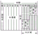
Fig. 13 schematically shows a slot structure configured for a long PUCCH structure according to another embodiment of the present invention.
As shown in fig. 13, in case of a slot structure in which the UL region is composed of 10 symbols, frequency hopping may be configured to be performed at the boundary of the eighth symbol, and whether each symbol is an RS transmission symbol or a UCI transmission symbol (or how multiplexing is applied between the RS and UCI, for example, which one of Alt 1 to Alt 5 is applied) may be configured in advance.
In this case, if it is determined that the actual symbol index of the long PUCCH is to be transmitted, it is possible to automatically determine whether the RS or UCI is to be transmitted or a position where frequency hopping is performed in each symbol according to the above determination. If the long PUCCH is configured to be transmitted in symbol # 5/6/7/10/11/12, RS may be transmitted in symbol # 6/11, UCI may be transmitted in symbol # 5/7/10/12, and frequency hopping may be performed after symbol # 7.
In order to configure a symbol index of a long PUCCH transmitted in the symbol # 5/6/7/10/11/12, transmission in each symbol may be indicated in the form of a bitmap, or a PUCCH start symbol (e.g., symbol #5) and the number of symbols (e.g., 3 symbols) in each hopping unit may be indicated.
Alternatively, the hopping boundary and/or the long PUCCH start symbol and/or the long PUCCH end symbol and/or the number of symbols in each hopping element and/or the DMRS position may be indicated UE-specifically (or UE group-commonly or cell-commonly) through L1 signaling (or higher layer signaling). In particular, the information about the hopping boundary may be signaled commonly for a UE group or commonly for a cell. In this case, if how to configure a long PUCCH type and/or PRU (PUCCH resource unit) is signaled according to a long PUCCH configuration method # 4, which will be described later, the number of symbols and/or DMRS position in each hopping unit may be configured. Furthermore, the hopping boundary signaled for UE group common (or cell common) can be equally applied to PUCCH as well as PUSCH (especially when DFT-s-OFDM is applied).
3.1.3 Long PUCCH configuration method # 3
In this section, a UCI configuration method when there are multiple UCI transmission symbols on a long PUCCH in one slot will be described in detail.
Only UCI may be present without any RS or RS and UCI may be FDM on the corresponding UCI transmission symbol. The UCI configuration method may be applied when a PUCCH of 2 symbols is configured by repeating a PUCCH of 1 symbol with RS and UCI FDM as shown in fig. 11(b), and when a PUCCH of 2 symbols is configured as shown in fig. 11 (c).
In the following description, the term "modulation symbol" may denote a modulated symbol (e.g., QPSK (quadrature phase shift keying) symbol, BPSK (binary phase shift keying) symbol), and the term "symbol" may denote an OFDM symbol or an SC-FDM (single carrier-frequency division modulation) symbol.
(1)Alt1:
When UCI is transmitted based on a sequence (e.g., a cyclically shifted Zadoff-Chu sequence) (e.g., a case where UCI is formed by multiplying a specific sequence by a modulation symbol or a case where UCI is mapped to cyclically shifted resources of a sequence), (1) when there is no time domain OCC, a modulation symbol of the same UCI bit may be repeated over a plurality of symbols, 2) after a modulation symbol of the same UCI bit is repeated over a plurality of symbols, time domain OCC may be applied, or 3) a modulation symbol of different UCI bits may be mapped to each symbol.
For example, when a 2-symbol PUCCH is configured with 2-bit UCI, 1) QPSK modulated (modulation) symbols of the corresponding 2-bit UCI may be repeated over multiple symbols (in which case each symbol sequence may have a different cyclic shift or a different root sequence), 2) time domain OCC may be applied after the corresponding QPSK modulated symbols are repeated over multiple symbols, or 3) the corresponding QPSK modulated symbols may be divided into 1-bit symbols and then each symbol may be mapped to a different symbol after BPSK modulation. In particular, in case 1), frequency hopping may be applied, and in case 2), frequency hopping may not be allowed. In addition, a different transmission method may be used in each symbol. For example, in case 1) or 3), for one symbol, UCI may be configured by multiplying a specific sequence by a modulation symbol, and for another symbol, UCI may be mapped to cyclic shift resources of the sequence.
(2)Alt2:
When transmitting UCI based on (modulation symbols of) coded bits, 1) the same (modulation symbols of) coded bits of the same UCI may be repeated over multiple symbols, 2) the same (modulation symbols of) coded bits of the same UCI may be repeated over multiple symbols, and then the time domain OCC may be applied, or 3) different (modulation symbols) coded bits of the same UCI may be mapped to each symbol.
For example, assume that N-bit UCI is transmitted. In this case, if there are X code bits to which rm (reed muller) coding or polarization coding is applied, 1) X code bits may be equally and repeatedly mapped to each symbol, 2) after X code bits are equally and repeatedly mapped to each symbol, time domain OCC may be applied, 3) X code bits may be mapped to M symbols (in this case, X/M bits are mapped to each symbol). Alternatively, as another example of case 3), although the same number of code bits (i.e., X code bits) are mapped to each symbol, X code bits may be mapped to each symbol based on a different coding scheme (e.g., a different redundancy version may be used, or a different rate matching pattern or puncturing pattern may be applied).
(3)Alt3:
When UCI is transmitted based on coded bits, modulation symbols of coded bits (where individual coding is applied per UCI) of different UCI may be mapped to each symbol. For example, when 20-bit UCI is transmitted in 2 symbols, the 20-bit UCI may be divided into 2 10-bit UCI, and coded bits obtained by applying separate coding every 10 bits may be mapped to each symbol.
As another example, when the UCI includes HARQ-ACK and CSI, separate codes are applied to the HARQ-ACK and CSI, respectively, and then the HARQ-ACK and CSI may be mapped to different symbols. Further, similarly, when UCI is transmitted based on a sequence, modulation symbols of different UCI may be mapped to each symbol.
The above alternatives can be combined with each other.
For example, when the long PUCCH is configured, in some symbols, UCI is configured according to Alt 1, and in other symbols, UCI may be configured according to Alt 2 or Alt 3.
Furthermore, in case of a 2-symbol PUCCH, the UCI part of the 2 symbols may be configured in a different manner (e.g., based on a sequence or coded bits).
For example, in one symbol, UCI may be FDM with RS and transmitted based on a sequence (e.g., a cyclically shifted Zadoff-Chu sequence) (i.e., UCI may be configured by multiplying a particular sequence by a modulation symbol, or UCI may be mapped to cyclically shifted resources of a sequence). On the other hand, another symbol may be configured with only UCI, and the UCI may be transmitted based on coded bits (with or without DFT and/or with or without frequency domain OCC).
As another example, the 2 symbols may all be in the form of RS/UCI FDM. In one symbol, UCI may be transmitted based on a sequence (e.g., a cyclically shifted Zadoff-Chu sequence) (i.e., UCI may be configured by multiplying a particular sequence by a modulation symbol, or UCI may be mapped to cyclically shifted resources of a sequence). On the other hand, another symbol may be configured with only UCI, and the UCI may be transmitted based on coded bits (with or without DFT and/or with or without frequency domain OCC).
In the above example, the UCI based on sequence transmission may be UCI of which reliability is extremely important, such as HARQ-ACK information, and the UCI based on coded bit transmission may be UCI of which reliability is relatively less important, such as CSI.
3.1.4. Long PUCCH configuration method # 4
If various PRUs (PUCCH resource units) that can constitute a hopping unit are defined, one long PUCCH in a specific slot may be composed of a combination of corresponding PRUs. In this case, the PRU may be configured differently according to the number of included symbols, UCI payload size, and the like.
Table 6 below shows an RPU configuration method according to the present invention.
[ Table 6]


In table 6, a low payload size means that the payload size is equal to or less than X bits (e.g., X ═ 2), a medium-low payload size means that the payload size is greater than X bits and equal to or less than Y bits (e.g., X ═ 2 and Y ═ 21), and a high payload size means that the payload size is greater than Y bits (e.g., Y ═ 21).
When the PRU is configured according to the number of symbols in each hopping unit as shown in table 6, a long PUCCH of symbols {4,5,6,7,8,9,10,11,12,13,14} which may exist in a specific slot may be configured as shown in table 7. In this case, the long PUCCH may be different according to whether frequency hopping is applied.
In addition, the rules described in sections 3.1 and 3.2 of the present invention that apply to the hopping unit can be applied to each PRU when frequency hopping is not applied.
[ Table 7]
| Long PUCCH type | Symbol # | With frequency hopping | Without |
| A | |||
| 4 | PRU_2+PRU_2 | PRU _2+ PRU _2 or | |
| B | |||
| 5 | PRU_2+PRU_3 | PRU _2+ PRU _3 or PRU _5 | |
| |
6 | PRU_3+PRU_3 | PRU _3+ PRU _3 or |
| D | |||
| 7 | PRU_3+PRU_4 | PRU _3+ PRU _4 or | |
| E | |||
| 8 | PRU_4+PRU_4 | PRU_4 | |
| F | |||
| 9 | PRU_4+PRU_5 | PRU_4 | |
| G | |||
| 10 | PRU_5+PRU_5 | PRU_5 | |
| H | |||
| 11 | PRU_5+PRU_6 | PRU_5+ | |
| I | |||
| 12 | PRU_6+PRU_6 | PRU_6 | |
| J | |||
| 13 | PRU_6+PRU_7 | PRU_6 | |
| K | |||
| 14 | PRU_7+PRU_7 | PRU_7+PRU_7 |
In table 7, PRU _4 may represent PRU _4a or PRU _4b in table 6, PRU _5 may represent PRU _5a or PRU _5b in table 6, PRU _6 may represent PRU _6a, PRU _6b, or PRU _6c in table 6, and PRU7 may represent PRU _7a, PRU _7bPRU _7c in table 6. Also, in case of PRU _ X + PRU _ Y, in a long PUCCH composed of (X + Y) symbols, PRU _ X may be composed of the previous X symbols and PRU _ Y may be composed of the subsequent Y symbols. In this case, it is considered that a shortened long PUCCH may be configured due to a short PUCCH and/or SRS that may be located at the rear of a given slot (e.g., the last N symbols, where N may be selected from the range of 1 to 3), where the number of symbols in a later-occurring PRU may be set higher than the number of symbols in the earliest-occurring PRU.
In this case, the DMRS position in each PRU may be configured as shown in table 8 below.
[ Table 8]
| Symbol # | # of RS symbol | | |
| PRU_2 | |||
| 2 | 1 | First of allOr | |
| PRU_3 | |||
| 3 | 1 | First or second or | |
| PRU_4a | |||
| 4 | 1 | First or second or third or | |
| PRU_4b | |||
| 4 | 2 | 1/3 or 2/3 | |
| |
5 | 1 | First or second or third or fourth or |
| PRU_5b | |||
| 5 | 2 | 2/4 or 2/3 or 3/4 | |
| |
6 | 1 | First or second or third or fourth or fifth or |
| PRU_6b | |||
| 6 | 2 | 2/5 or 3/4 | |
| |
6 | 3 | 1/3/5 or 2/3/4 or 3/4/5 or 2/4/6 or 2/3/5 or 2/4/5 |
| |
7 | 1 | First or second or third or fourth or fifth or sixth or |
| PRU_7b | |||
| 7 | 2 | 1/4 or 2/6 or 3/4 or 4/5 | |
| |
7 | 3 | 2/4/6 or 3/4/5 |
When the long PUCCH type is configured according to the PRU combination shown in table 7, the DMRS location may be different in each PRU. In particular, DMRS locations may be mirrored with reference to boundaries between PRUs. For example, when the long PUCCH type a is configured by PRU _2+ PRU _2, an RS may be located at a first symbol in the first PRU _2 and an RS may be located at a second symbol in the second PRU _ 2. As another example, when the long PUCCH type G is configured by PRU _5+ PRU _5, the RS may be located at the second/third symbol (PRU _5b) in the first PRU _5, and the RS may be located at the third/fourth symbol (PRU _5b) in the second PRU _ 2.
Referring to table 8, if there are only 1 RS symbol, the RS may be located in front of the PRU for early decoding UCI, or the RS may be located approximately in the middle of the RRU in consideration of channel estimation performance. If the number of available RS locations in each PRU is more than 2, the BS can inform the UE of the RS locations to be actually used via L1 signaling or higher layer signaling.
When one long PUCCH is configured by a combination of 2 PRUs as shown in table 7, the number of symbols in each PRU may be different if the corresponding long PUCCH is composed of an odd number of symbols. In this case, the number of RS symbols or the number of UCI symbols may be equal in each PRU. For example, a long PUCCH type H consisting of 11 symbols may be configured by a combination of PRU _5 and PRU _ 6. In this case, the long PUCCH type has a high payload (or a medium payload), and the number of RS symbols in PRU _5 and the number of RS symbols in PRU _6 may be set to 1 in order to match the number of RS symbols. Alternatively, both the number of UCI symbols in PRU _5 and the number of UCI symbols in PRU _6 may be set to 4 in order to match the number of UCI symbols.
As an embodiment of DMRS location in each PRU, a long PUCCH structure as shown in the following table may be applied.
[ Table 9]


In case of a long PUCCH supporting a large payload size, only 1 RS symbol may be located in each frequency hop. In this case, if 2 symbols are included in one hop, an RS symbol is located at the first symbol. If 3 or 4 symbols are included in one hop, an RS symbol is located at the second symbol. If 5 or 6 symbols are included in one hop, an RS symbol is located at the third symbol. If 7 symbols are included in one hop, an RS symbol may be located at the fourth symbol.
The above method can be applied to PUCCH formats of medium payload size, where frequency domain OCC is applied as LTE PUCCH format 5.
Meanwhile, in case of applying a PUCCH format of a medium payload size of time domain OCC, if the number of symbols included in one hop is 6 or 7, the number of RS symbols in each hop may be 2.
Even with large payload sizes (e.g., in high mobility scenarios such as 500 km/h), 2 DMRS symbols may be needed at a particular hop of a long PUCCH that performs hopping. For example, referring to table 9, when 6 or 7 symbols are included in a specific hop of a long PUCCH performing hopping, 2 DMRS symbols may be required in each hop although the payload size is large. In this case, as shown in table 9, DMRS symbol positions may be determined as the second symbol and the second last symbol in a hop.
However, considering that one symbol interval may decrease as the subcarrier spacing increases, the influence on mobility may be reduced by increasing the subcarrier spacing increase. In view of this, as the subcarrier spacing increases, the number of DMRS symbols in one hop of a long PUCCH in which hopping is performed may decrease.
For example, when a subcarrier spacing is equal to or less than X kHz (e.g., X ═ 15 or 30) and the number of symbols in one hop of a long PUCCH performing hopping is equal to or less than Y (e.g., Y ═ 6 or 7), 2 DMRS symbols can be transmitted in each hop even with a large payload size. In contrast, when the subcarrier spacing is equal to or less than X kHz and the number of symbols in one hop of the long PUCCH performing hopping is greater than Y (e.g., Y ═ 6 or 7), 1 DMRS symbol may be transmitted in each hop.
In this case, as shown in table 9, DMRS symbol positions may be determined as the second symbol and the second last symbol.
In contrast, when the subcarrier spacing is greater than X kHz, the number of DMRS symbols per hop of the long PUCCH that performs hopping may be always set to 1.
Alternatively, the number of DMRS symbols per hop may be configured based on a combination of a payload size and a subcarrier spacing.
For example, when the subcarrier spacing is equal to or less than X kHz (e.g., X15 or 30) and the payload size (per PRB) is equal to or less than Z (e.g., Z50 bits per PRB), if the number of symbols in one hop of the long PUCCH performing hopping is equal to or less than Y (e.g., Y6 or 7), 2 DMRS symbols may be transmitted in each hop even with a large payload size. Conversely, if the number of symbols in one hop of the long PUCCH performing hopping is greater than Y (e.g., Y ═ 6 or 7), then 1 DMRS symbol may be transmitted in each hop.
In this case, as shown in table 9, DMRS symbol positions may be determined as the second symbol and the second last symbol.
In contrast, when the subcarrier spacing is greater than X kHz and the payload size (per PRB) is greater than Z, the number of DMRS symbols per hop of the long PUCCH that performs hopping may always be set to 1.
3.1.5. Long PUCCH configuration method # 5
When frequency hopping is applied, the number and location of DM-RS symbols in each hop can be determined according to the following rules, taking into account early decoding, power transient period, and DM-RS spacing.
(1) In case of a mapping method in which both the front loading DM-RS (i.e., early decoding) and the DM-RS are uniformly distributed are considered, the DM-RS position can be configured according to the number of symbols occupying the PUCCH as shown in the following table.
[ Table 10]

(2) In case of a mapping method in which UCI symbols are located at the first/last symbol (except DM-RS symbol) of each hop in consideration of a power transient period, DM-RS positions may be configured according to the number of symbols occupying PUCCH as shown in the following table.
[ Table 11]


(3) In case of the mapping method in which the maximum DM-RS symbol number per hop is set to 2, mirroring is applied in case of hopping while DM-RS positions can be configured according to the number of symbols occupying PUCCH as shown in the following table in consideration of uniform DM-RS distribution.
[ Table 12]

(4) In case of the mapping method in which the number of DM-RS symbols per hop is set to 1, mirroring is applied in case of non-hopping while DM-RS positions can be configured according to the number of symbols occupying PUCCH as shown in the following table in consideration of uniform DM-RS distribution.
[ Table 13]

3.1.6. Long PUCCH configuration method # 6
In this section, a method for determining a duration per PUCCH and the number of DM-RS symbols per hop when frequency hopping is performed and when frequency hopping is not performed will be described in detail. In particular, the configuration described in this section can only be applied when the UCI payload size is greater than K bits (e.g., K ═ 2).
First, when frequency hopping is performed, if the length of at least one hop is greater than X symbols, whether the number of DM-RS symbols of the corresponding hop is 1 or 2 may be configured through UE-specific RRC signaling (method 1), or if the length of two hops is greater than X symbols, whether the number of DM-RS symbols of all hops is 1 or 2 may be configured through UE-specific RRC signaling (method 2). In these methods, one hop, which is not configured with the number of DM-RS symbols, may be configured to always include 1 DM-RS symbol.
For example, in case of X ═ 5, assuming that similar to the long PUCCH type H, including 11 symbols, frequency hopping is performed, one hop is composed of 5 symbols, and the other hop is composed of 6 symbols.
In this case, according to method 1,1 DM-RS symbol is configured in a hop of 5 symbols, but it may be configured whether there are 1 or 2 DM-RS symbols in a hop of 6 symbols. However, according to method 2, since there are 5-symbol hops, each of two hops can be configured with 1 symbol.
In case of method 2, it can be configured whether the number of DM-RS symbols per hop is 1 or 2 only when the length of each hop is greater than 5 symbols.
When frequency hopping is not applied, if the number of symbols included in the corresponding long PUCCH is equal to or less than Y, the DM-RS symbol number may be always set to 1. In this case, the Y value may be equal to the X value in method 1 or method 2.
Additionally/alternatively, if the number of symbols included in the long PUCCH is greater than Y and equal to or less than Z, the DM-RS symbol number may be always set to 2. In this case, according to method 1, the equations of Y ═ X and Z ═ 2 × X can be satisfied. Further, according to method 2, the equations of Y ═ X and Z ═ 2 × X +1 can be satisfied.
Additionally/alternatively, if the number of symbols included in the long PUCCH is W, whether the number of DM-RS symbols is 2 or 3 may be configured through UE-specific RRC signaling. In this case, according to method 1, the equation of W ═ 2 × X +1 can be satisfied. For example, in case of X-5, if 11 symbols are included and frequency hopping is not applied, it may be configured whether the DM-RS symbol number is 2 or 3.
Additionally/alternatively, if the number of symbols included in the long PUCCH is greater than Q, whether the number of DM-RS symbols is 2 or 4 may be configured through UE-specific RRC signaling. In this case, according to method 1 or method 2, the equation of Q ═ 2 × X +1 can be satisfied.
3.2. Multiplexing method
In this section, a method for supporting multiplexing between long PUCCHs or between sPUCCH and long PUCCH will be described in detail.
3.2.1. Multiplexing method # 1
In case of UCI transmission (in a hopping unit), multiplexing between UEs (or antenna ports) may be supported through frequency domain OCC. In this case, the length of the OCC may be different according to the number of symbols included in the hopping unit.
Also, in case of UCI transmission based on OFDM, OCC may be applied to a frequency domain, and in case of UCI transmission based on DFT-s-OFDM, OCC may be applied to a virtual frequency domain before DFT to maintain PAPR (peak to average power ratio).
In particular, when the number of UCI symbols per hopping unit is equal to or less than a certain value (e.g., 1 symbol), or when the amount of time resources/the amount of frequency resources allocated to UCI is equal to or less than a certain value (e.g., 1 symbol × 12 REs), the length of the frequency domain OCC may be set to 1, or the length of the frequency domain OCC may not be configured.
For example, when UCI is transmitted in 2 symbols, a (virtual) frequency domain resource per symbol may be divided into two parts, and an OCC of length 2 (e.g., [1,1], [1, -1]) may be applied. In this case, as a method for dividing (virtual) frequency domain resources, a comb type method or a method for dividing N REs into two parts, each part corresponding to N/2 REs, may be used.
In addition, when UCI is transmitted in 3 symbols, a (virtual) frequency domain resource may be divided into three parts, and an OCC of length 3 may be applied. In this case, as a method for dividing (virtual) frequency domain resources, a comb type method or a method for dividing N REs into three parts, each part corresponding to N/3 REs, may be used.
According to these methods, the coding rate can be maintained even when the number of UCI symbols varies.
In addition, the length of the frequency domain OCC may be determined according to the UCI code rate or the UCI symbol number.
(1)Alt 1:
The length of the frequency domain OCC may be determined with reference to a specific UCI code rate (R).
For example, the value of K may be determined such that a code rate calculated based on the allocated number of UCI symbols N and the OCC length K becomes a maximum code rate not exceeding R. In other words, the OCC length may increase with more symbols configured.
As another example, when the OCC length is set to K with reference to a specific UCI symbol number N (in this case, the UCI code rate is equal to or less than R), if the UCI symbol number becomes less than N and the code rate exceeds R due to combination with the OCC length K, the OCC length may be set to be lower than K.
(2)Alt 2:
The length of the frequency domain OCC may be determined with reference to a specific UCI symbol number (L).
For example, if the number N of allocated UCI symbols is less than L, a frequency domain OCC having a relatively short length may be applied. In contrast, if the number N of allocated UCI symbols is equal to or greater than L, a frequency domain OCC having a relatively long length may be applied.
As another example, the OCC length may be set to K when the number of UCI symbols is equal to or greater than a specific UCI symbol number L. When the number of UCI symbols is less than L, the OCC length may be set to be lower than K.
The method may be equally applied to PUCCH with FDM between UEs and using only partial PRBs.
For example, when a PUCCH composed of 12 REs is multiplexed between 2 UEs, each UE may use 6 consecutive REs, 6 odd REs, or 6 even REs for PUCCH transmission.
According to Alt 1, the number of REs available in the frequency domain may be determined with reference to a specific UCI code rate (R).
For example, the K value may be determined such that a code rate calculated based on the allocated UCI symbol number N and RE number K becomes a maximum code rate not exceeding R. In other words, the number of REs K may decrease as more symbols are configured.
As another example, when the number of REs is set to K with reference to a specific number N of UCI symbols (in this case, UCI code rate is equal to or less than R), if the number of UCI symbols becomes less than N and the code rate exceeds R due to combination with the number K of REs, the number of REs may be set to be higher than K.
According to Alt 2, the number of REs available in the frequency domain may be determined with reference to a specific number of UCI symbols (L).
For example, if the number of allocated UCI symbols N is less than L, a relatively large number of REs may be applied. In contrast, if the number N of allocated UCI symbols is equal to or greater than L, a relatively small number of REs may be applied.
As another example, when the number of UCI symbols is equal to or greater than a specific UCI symbol number L, the number of REs may be set to K. When the UCI symbol number is less than L, the RE number may be set higher than K.
3.2.2. Multiplexing method # 2
If sPUCCH is configured based only on sequences as mentioned in Alt 5 of section 3.1.1, sPUCCH may be multiplexed with RS symbols and/or (sequence-based) UCI symbols of the long PUCCH. In this case, which time domain resources and/or frequency domain resources are used for sPUCCH transmission may be used as UCI.
Fig. 14 illustrates a method for multiplexing a sPUCCH with a long PUCCH according to an embodiment of the present invention.
In fig. 14, if the sequence-based sPUCCH multiplexed with the long PUCCH is transmitted in symbol #9 (with CDM of the long PUCCH RS), it may represent ACK. If sPUCCH is transmitted in symbol #12 (CDM with the long PUCCH RS), it may indicate NACK. In other words, the resource for the sPUCCH transmitted from the UE may be determined according to whether ACK or NACK is transmitted.
Fig. 15 illustrates a method for multiplexing the sPUCCH with the long PUCCH according to another embodiment of the present invention.
In fig. 15, to support CDM between the long PUCCH and the sPUCCH, symbols # 8/#9 are allocated to the UE1 as ACK/NACK resource, symbols #10/#11 are allocated to the UE2 as ACK/NACK resource, and symbols # 12/#13 may be allocated to the UE3 as ACK/NACK resource.
In particular, CDM can be supported by configuring RS and UCI for each symbol based on a sequence and allocating a different Cyclic Shift (CS) value to each UE. In this case, when K CS values are allocated to sPUCCH and the remaining (N-K) CS values are allocated to long PUCCH in total of N CS values, sequence available resources corresponding to K x the number of long PUCCH symbols (or the number of long PUCCH RS symbols) may be used for sPUCCH.
Referring to fig. 15, when each symbol has 12 CS resources, a twelfth CS resource corresponding to one of the 12 CS resources may be allocated for the sPUCCH. In this case, the long PUCCH shown in fig. 15 is a 6-symbol long PUCCH, and thus up to 6 sequence resources (or sPUCCH resources) may be used. Among the 6 sequence resources, a twelfth CS resource of symbol # 8/#9 may be allocated as an ACK/NACK resource to the UE1, a twelfth CS resource of symbol # 10/#11 may be allocated as an ACK/NACK resource to the UE2, and a twelfth CS resource of symbol # 12/#13 may be allocated as an ACK/NACK resource to the UE 3.
3.2.3 multiplexing method # 3
When frequency hopping is performed on the basis of 2 symbols (i.e., every 2 symbols), performance may be degraded due to a power transient period. Accordingly, an RS/UCI structure considering attributes and a multiplexing method thereof will be described in detail in this section.
For example, a restriction may be imposed to avoid setting RS or UCI only between adjacent symbols located at a hop boundary.
For example, when one hopping unit is configured for every 2 symbols for a long PUCCH composed of 4 symbols (i.e., symbols # 9/#10/#11/#12), if both the symbol # 10 and the symbol # 11 are RS symbols (or UCI symbols), the influence on the power transient period may increase, and thus such RS/UCI configuration may not be allowed.
Alternatively, if symbol # 9 and symbol # 11 are RS symbols, the power mask may be configured to completely maintain the ON duration of the symbol in which the RS will be transmitted. In other words, the power mask may be configured such that a power transient period switched from OFF to ON and/or a power transient period switched from ON to OFF is not included in a symbol region where RS is to be transmitted.
Fig. 16 schematically illustrates a method for supporting multiplexing between long PUCCHs according to an embodiment of the present invention.
As shown in fig. 16, if the long PUCCH is configured such that X symbol gaps (e.g., X > ═ 1) exist between hopping units, the influence on the power transient period can be mitigated. In addition, if the UE shares the RS in each hopping unit, the multiplexing capacity can be maximized as well. In this case, as a method for sharing the RS in a specific symbol, FDM/CDM may be applied to each RE (or RE group).
3.2.4. Multiplexing method # 4
As described in section 3.1.3 or section 3.1.4, UCI bits may be transmitted in a plurality of symbols included in one hopping unit, time domain OCC may be applied to support CDM between UEs, and OCC length may vary according to the number of symbols included in the hopping unit.
Alternatively, as described in section 3.2.1, in case of UCI transmission (in a hopping unit), multiplexing between UEs (or antenna ports) may be supported through frequency domain OCC. In this case, the length of the OCC may be different according to the number of symbols included in the hopping unit.
In this section, the RS configuration method when the OCC length changes will be described in detail.
Specifically, if the RS sequence has a fixed length, a Cyclic Shift (CS) interval of the RS may vary according to the OCC length. In other words, in the case where the RS sequence has a fixed length, as the OCC length increases, the CS interval of the RS may also decrease.
For example, assume that 12 CSs are used and an RS consists of 12 REs. In this case, if the length of the OCC is 2, 2 CSs may be allocated at interval 6. If the length of the OCC is 4, 4 CSs may be allocated at interval 3.
If the OCC lengths of each of the hopping units are different, the RS can be equally allocated with reference to the hopping unit having a short OCC length.
For example, assume that 12 CSs are used and an RS consists of 12 REs. In case of a long PUCCH composed of 2 hopping units, if the OCC length of one hopping unit is 2 and the OCC length of another hopping unit is 4, the CS may be commonly allocated at an interval of 6 with reference to the hopping unit having the OCC length of 2.
Alternatively, the CS may be allocated differently in each hop unit. For example, the CS may be allocated at interval 6 for the RS in the hopping unit with OCC length 2, and the CS may be allocated at interval 3 for the RS in the hopping unit with OCC length 4. However, for the RS in the hopping unit having the OCC length of 4, only 2 specific CSs can be configured to be valid among 4 CSs allocated at interval 3.
[ Table 14]

Specifically, referring to table 14, when each hop unit has a different OCC length, RSs can be equally allocated with reference to hop units having a short OCC length.
For example, referring to a column named "DMRS positions with hopping" in table 14, when the number of symbols is 4/5, 1 CS (e.g., CS index 0) is configured since the short OCC length is 1. When the number of symbols is 6/7, since the short OCC length is 2, 2 CSs (e.g., CS indices 0 and 6) are configured. When the number of symbols is 8/9, since the short OCC length is 3, 3 CSs are configured (e.g., CS indices 0,4, and 8). When the number of symbols is 10/11/12/13, since the short OCC length is 4, 4 CSs are configured (e.g., CS indices 0,3,6, and 9).
When frequency hopping is not applied to the long PUCCH in one slot, the above method may be equally applied to the entire long PUCCH.
3.2.5. Multiplexing method # 5
As described in section 3.1.4, frequency hopping may or may not be applied to the long PUCCH in one slot. A method of applying the time domain OCC according to whether frequency hopping is applied will be described in detail in this section.
Specifically, when frequency hopping is not performed, a time domain OCC having a long OCC length may be applied.
For example, as described in section 3.1.4, the X + Y symbol composed of the long PUCCH may be composed of PRU _ X and PRU _ Y. When PRU _ X includes a UCI symbols (where a < X) and PRU _ Y includes B UCI symbols (where B < Y), if frequency hopping is applied, a time domain OCC of length a and a time domain OCC of length B may be applied to PRUs, respectively. In contrast, if frequency hopping is not applied, the time domain OCC of length a and the time domain OCC of length B may be applied to the PRU, respectively, in the same manner as when frequency hopping is applied (Opt 1). Alternatively, a time domain OCC (Opt 2) of length (a + B) may be applied.
In this case, a method for transmitting UCI when applying a time domain OCC of length (a + B) may be different according to how UCI is configured.
For example, when the same UCI is repeated on a hop-by-hop unit basis or on a PRU-by-PRU basis like the LTE PUCCH format 1a/1b, the same UCI transmission method can be applied regardless of whether Opt 1 or Opt 2 is applied.
As another example, when code bits of the UCI payload are distributed and transmitted on a hop-by-hop unit or PRU-by-PRU basis (i.e., when frequency hopping is performed) similarly to the LTE PUCCH format 3, if Opt 2 is applied, the UCI transmission method may be changed. That is, when Opt 2 is applied, coded bits are not distributed one PRU by one but repeatedly transmitted.
In addition, when Opt 1 is applied, the corresponding long PUCCH can be easily CDM with another PUCCH performing frequency hopping. A resource allocation method for disabling hopping of the long PUCCH will be described in detail below.
Fig. 17 illustrates PRB indices applicable to a long PUCCH according to an embodiment of the present invention.
As shown in fig. 17, when a PRB index is applied to a long PUCCH that performs frequency hopping, the same PRB index may also be applied to a long PUCCH that disables frequency hopping. In this case, in the case of a long PUCCH in which frequency hopping is disabled, only the frequency domain resource for the first hop is allocated, but it can be assumed that the corresponding frequency domain resource is allocated to the second hop.
3.2.6. Multiplexing method # 6
If frequency hopping is applied to a long PUCCH in one slot (or multiple slots), the number of symbols per frequency hopping may be different, and thus the time domain OCC applied to each hop may have a different length. In particular, as in LTE PUCCH format 1a/1b, when UCI and RS are TDMed, time domain OCC may be applied to RS symbols and UCI symbols.
For example, in case of the long PUCCH type H described in section 3.1.3, which consists of 11 symbols, the first and second hops may correspond to PRU _5b (i.e., 2 RS symbols and 3 UCI symbols) and PRU _6c (i.e., 3 RS symbols and 3 UCI symbols), respectively (conversely, the first and second hops may correspond to PRU _6c and PRU _5b, respectively).
The first hop of the corresponding long PUCCH has the smallest number of RS symbols, i.e., 2 RS symbols, and thus only up to 24 UEs can be CDM in consideration of 12 CS resources.
At this time, if 2 specific OCCs and 12 CSs are used as PUCCH resource indexes among 3 OCCs available for different RSs and UCIs, each of which consists of 3 symbols (i.e., OCCs of length 3 can be used), or if 8 specific CSs among all 3 available OCCs and 12 CSs are used as PUCCH resource indexes, maximum UE multiplexing capacity can be achieved.
Here, the index of a specific 8 CSs may be set to {0,1,3,4,6,7,9,10} or {0,2,3,5,6,8,9,11 }.
Further, if the offset value of the CS is set to 2, only 6 CS resources among 12 CS resources may be actually used (i.e., a CS with an index of {0,2,4,6,8,10} may be used). In this case, if 2 specific OCCs and 6 CSs are used as PUCCH resource indexes, among 3 OCCs available for different RSs and UCIs, each of which consists of 3 symbols (i.e., OCCs of length 3 can be used), or if 4 specific CSs among all 3 available OCCs and 6 CSs are used as PUCCH resource indexes, maximum UE multiplexing capacity (i.e., 12 UEs) can be achieved. In this case, the indices of the 4 specific CSs may be some of the 6 available CS resources (e.g., {0,2,6,8} or {0,4,6,10}) or determined in a uniformly distributed manner (e.g., {0,3,6,9 }).
As another example, in case of the long PUCCH type D described in section 3.1.3, which consists of 7 symbols, the first and second hops may correspond to PRU _3 (i.e., 1 RS symbol and 2 UCI symbols) and PRU _4b (i.e., 2 RS symbols and 2 UCI symbols), respectively (conversely, the first and second hops may correspond to PRU _4b and PRU _3, respectively).
Since the first hop of the corresponding long PUCCH has the smallest number of RS symbols, i.e., 1 RS symbol, only up to 12 UEs can be CDM in consideration of 12 CS resources.
At this time, if 1 specific OCC (e.g., [ +1+1]) and 12 CSs are used as a PUCCH resource index (Alt 1) among 2 OCCs available for different RSs and UCIs (i.e., OCCs of length 2 can be used), or if specific 6 CSs (e.g., CSs with an index of {0,2,4,6,8,10} among all 2 available OCCs and 12 CSs) are used as a PUCCH resource index (Alt 2), the maximum UE multiplexing capacity can be maintained at the same level.
Further, if the offset value of the CS is set to 2, only 6 CS resources among 12 CS resources may be actually used (i.e., a CS with an index of {0,2,4,6,8,10} may be used). In this case, according to Alt 2, only 3 specific CSs among 6 available CS index resources may be used as PUCCH resource indexes. In this case, the index of a specific 3 CSs may be set to 0,4, 8.
Fig. 18 schematically shows a long PUCCH allocated to 3 UEs.
As a method for PUCCH resource indexing, according to Alt 1, PUCCH resource indexing may be performed only for CS without considering OCC, and according to Alt 2, PUCCH resource indexing may be preferentially performed for OCC.
In this case, the method depicted in fig. 18 may be regarded as a method for improving UE multiplexing capacity. At this time, since up to 6 CSs are available in each symbol of the first hop, the UE multiplexing capacity can be increased to 18.
3.2.7. Multiplexing method # 7
As described above in section 3.1.4 or section 3.1.5 and with reference to various multiplexing methods, UCI bits are transmitted in multiple symbols in one hopping unit, and the length of an available time domain OCC may vary according to the number of symbols included in the hopping unit in order to support CDM between UEs.
However, considering a trade-off relationship between UE multiplexing capacity and supportable payload size, the UE multiplexing capacity may be limited in order to increase the supportable payload size.
Therefore, a method for increasing a supportable payload size while limiting a UE multiplexing capacity to at most 2 UEs using a PUCCH format to which the time domain OCC is applied will be described in the present invention.
First, a case where 4 UCI symbols are allocated per hop will be described. When 4 UCI symbols are allocated per hop, the configuration between DM-RS and UCI symbols may be determined as follows: uuru, ruuuu, uuru, etc. as described in section 3.1.4 or section 3.1.5.
Fig. 19 schematically illustrates a method for configuring 4 UCI symbols according to an embodiment of the present invention.
When 4 UCI symbols are indexed by time as follows: u (1) U (2) U (3) U (4), each UE repeatedly transmits UCI in U (1) and U (2) and then repeatedly transmits UCI in U (3) and U (4). Thereafter, each UE may perform transmission by applying the allocated time domain OCC of length 2 (as shown in fig. 19). Assuming that 2 UEs to be CDM on the corresponding PUCCH are UE # 1 and UE # 2, OCC [ +1, +1] is allocated to UE # 1, and OCC [ +1, -1] may be allocated to UE # 2. In this case, UE # 2 may repeatedly transmit UCI in U (1) and U (2) and perform transmission by multiplying the time domain cover code [ +1, -1] allocated per symbol. Further, UE # 2 may repeatedly transmit UCI in U (3) and U (4) and perform transmission by multiplying the time domain cover code [ +1, -1] allocated per symbol.
Although it is assumed in the above example that the OCC applied to [ U (1), U (2) ] is the same as the OCC applied to [ U (3), U (4) ], different OCCs may be allocated and applied.
Next, a case where 5 UCI symbols are allocated per hop will be described in detail. When 5 UCI symbols are allocated per hop, the configuration between DM-RS and UCI symbols may be determined as follows: uuuuuu, uuuuuuuru, uuuuruu, etc., as described in section 3.1.4 or section 3.1.5. When 5 UCI symbols are indexed by time as follows: u (1) U (2) U (3) U (4) U (5), one of the following two methods may be applied.
(1) Method A
Each UE may repeatedly transmit UCI with the following 3 symbols: u (1), U (2), and U (3), apply the allocated time domain OCC of length 3, repeat transmission of UCI with U (4) and U (5), and then perform transmission by applying the allocated time domain OCC of length 2. In this case, although 3 allocated OCCs of length 3 may be applied to [ U (1), U (2), U (3) ], a specific 2 OCCs among them may be used as OCC resources to be actually allocated to 2 UEs to be CDM.
This method can be effectively used when the interval between the current 3 UCI symbols is shorter than the interval between the last 3 UCI symbols in terms of the interval between UCI symbols to which OCC is to be applied like UUURUU.
(2) Method B
Each UE may repeatedly transmit UCI with the following 2 symbols: u (1) and U (2), applying the allocated time domain OCC of length 2, repeatedly transmitting UCI with the following 3 symbols: u (3), U (4), and U (5), and then performs transmission by applying the allocated time domain OCC of length 3. In this case, although 3 allocated OCCs of length 3 may be applied to [ U (1), U (2), U (3) ], a specific 2 OCCs among them may be used as OCC resources to be actually allocated to 2 UEs to be CDM.
This method can be effectively used when the interval between the last 3 UCI symbols is shorter than the interval between the first 3 UCI symbols, in terms of the interval between UCI symbols to which OCC will be applied like UURUUU.
The case of allocating 6 UCI symbols per hop will be described in detail below. When 6 UCI symbols are allocated per hop, the configuration between DM-RS and UCI symbols may be determined to be uuuruuuu as described in section 3.1.4 or section 3.1.5. If 6 UCI symbols are indexed by time as follows: u (1) U (2) U (3) U (4) U (5) U (6), one of the following two methods may be applied.
1) Method 1
Each UE may repeatedly transmit UCI with the following 3 symbols: u (1), U (2), and U (3), applying the allocated time domain OCC of length 3, and repeatedly transmitting UCI with the following 3 symbols: u (4), U (5), and U (6), and then performs transmission by applying the allocated time domain OCC of length 3. In this case, although 3 allocated OCCs of length 3 may be applied to [ U (1), U (2), U (3) ] and [ U (4), U (5), U (6) ], respectively, a specific 2 OCCs among them may be used as OCC resources to be actually allocated to 2 UEs to be CDM. Alternatively, when applying all 3 allocated length 3 OCCs, CDM may be supported between at most 3 UEs.
2) Method 2
After transmitting UCI with the following 3 symbols: u (1) U (2) U (3), each UE repeatedly transmits UCI with the following 3 symbols: u (4) U (5) U (6), and then performs transmission by applying a time domain OCC of length 2. Assuming that 2 UEs to be CDM on the corresponding PUCCH are UE # 1 and UE # 2, OCC [ +1, +1] is allocated to UE # 1, and OCC [ +1, -1] may be allocated to UE # 2. In this case, UE # 2 may repeatedly transmit UCI in U (1) and U (2) and perform transmission by multiplying the time domain cover code [ +1, -1] allocated per symbol. Further, UE # 2 may repeatedly transmit UCI in U (1) U (2) U (3) and U (4) U (5) U (6), and perform transmission by multiplying [ +1, +1, +1, -1, -1, -1] per symbol by the allocated time domain cover code [ +1, -1 ].
3) Method 3
Each UE may repeatedly transmit UCI with the following 2 symbols: u (1) and U (2), applying the allocated time domain OCC of length 2, repeatedly transmitting UCI with the following 2 symbols: u (3) and U (4), applying the allocated time domain OCC of length 2, repeatedly transmitting UCI with the following 2 symbols: u (5) and U (6), and then performs transmission by applying the allocated time domain OCC of length 2.
4) Method 4
Although method 4 is similar to method 3, in method 4, a different pair of symbols is used for UCI transmission compared to method 3. For example, each UE may repeatedly transmit UCI with the following 2 symbols: u (1) and U (4), applying the allocated time domain OCC of length 2, repeatedly transmitting UCI with the following 2 symbols: u (2) and U (5), applying the allocated time domain OCC of length 2, repeatedly transmitting UCI with the following 2 symbols: u (3) and U (6), and then performs transmission by applying the allocated time domain OCC of length 2.
When the multiplexing capacity of at most 2 UEs is always provided as described above, the CS value applied to the DM-RS may be set to one of {0,6 }.
Further, when frequency hopping is performed, if the number of UCI symbols varies from hop to hop, the proposed method may be applied according to the number of UCI symbols in each hop, respectively. On the other hand, when frequency hopping is not applied, if the long PUCCH is composed of 7 or less symbols, the method may be applied according to the number of UCI symbols in the entire PUCCH in the corresponding slot. In contrast, if the long PUCCH is composed of more than 7 symbols, UCI and OCC may be transmitted using a method used when frequency hopping is performed on the PUCCH of the same length.
3.2.8. Multiplexing method # 8
A long PUCCH transmitted in one slot may include a minimum of 4 symbols to a maximum of 14 symbols. DMRS and data symbols in the long PUCCH may be TDMed if UCI payload transmitted on the long PUCCH is small. In this case, the data symbols may be transmitted by multiplying (i.e., by sequence modulation) the sequence by modulated symbols (e.g., BPSK or QPSK).
In this case, the DMRS symbols are interleaved with the data symbols in the time domain. For example, assuming that a symbol index starts with an index of 0, a DMRS symbol may be transmitted with an even number of symbol indexes, and a data symbol may be transmitted with an odd number of symbol indexes. For example, a 4-symbol PUCCH may be configured as follows: the RS/data/RS/data and PUCCH of 5 symbols may be configured as follows: RS/data/RS.
In this configuration, CDM between UEs may be allowed on the same time/frequency resources, or may be supported by a combination of sequence Cyclic Shift (CS) and time domain OCC. For example, the maximum number of UEs capable of CDM may be determined according to the number of symbols included in the long PUCCH or the length N and whether frequency hopping is applied as shown in the following table.
[ Table 15]

Basically, assuming that the frequency domain resource is 1 RB (i.e., 12 REs of 12 subcarriers), the maximum UE multiplexing capacity that can be supported only by the CS is 12 UEs. In this case, as the number of available OCCs increases, the UE multiplexing capacity may also increase.
For example, referring to table 15, in case of a long PUCCH composed of 4 symbols, if hopping is performed, 1 RS symbol and 1 data symbol exist in each hop. In this case, a CDM capacity of up to 12 UEs may be supported only by CSs without any time domain OCCs.
As another example, referring to table 15, in case of a long PUCCH composed of 8 symbols, if hopping is performed, there are 2 RS symbols and 2 data symbols in each hop. In this case, a CDM capacity of up to 12 UEs may be supported by combining CS and 2 length-2 time domains OCC.
Alternatively, in the case of a long PUCCH composed of a specific number of symbols, the number of OCCs/CSs may vary according to DMRS/data when OCC and CS are combined.
In case of a long PUCCH consisting of 7 symbols, if hopping is applied, one hop may consist of 2 DMRS symbols and 1 RS symbol, and another hop may consist of 2 DMRS symbols and 2 RS symbols (as described in section 3.2.6). In this case, without any OCC, a CDM capacity of up to 12 UEs can be supported by using 2 OCCs of length 2 and 6 CSs for DMRS and RSs present on 2 symbols, and using 12 CSs for RSs present on 1 symbol.
Similarly, in case of a long PUCCH consisting of 11 symbols, if hopping is applied, one hop may consist of 3 DMRS symbols and 2 RS symbols, and another hop may consist of 3 DMRS symbols and 3 RS symbols (as described in section 3.2.6). In this case, by using 3 length-3 OCCs and 8 CSs for DMRS and RSs present on 3 symbols, and 2 length-3 OCCs and 12 CSs for RSs present on 2 symbols, CDM capacity of up to 24 UEs can be supported.
When no frequency hopping is performed, if N is set to 4/5/6/7 (N4/5/6/7), multiplexing with a long PUCCH that performs frequency hopping needs to be considered.
Accordingly, the structure without (w/o) hopping with N-4 needs to be equal to the structure with (w /) hopping with N-8, and each hop comprises 4 symbols in order to facilitate multiplexing between 2 PUCCHs.
Thus, it may be desirable that the maximum UE multiplexing capacity without hopping, N-4/5, is set equal to the maximum UE multiplexing capacity with hopping, N-8/9/10/11, and the maximum UE multiplexing capacity with hopping, N-6/7, is set equal to the maximum UE multiplexing capacity with hopping, N-12/13/14.
Also, "maximum UE multiplexing capacity" in the case where N is 8/9/10/11/12/13/14 without frequency hopping may be set to be equal to "maximum UE multiplexing capacity" when hopping is performed with the same N value. This is because, in the case of no hopping and N-8, if the maximum UE multiplexing capacity is set to 48 using a time domain OCC of length 4, it cannot be multiplexed with the case of no hopping and N-4 or hopping and N-8, and orthogonality of the OCC may not be maintained in an environment with a large delay spread.
In addition, if the OCC structure without hopping is set to be equal to the OCC structure when the same number of symbols are used with hopping in order to maintain orthogonality with multiplexing of other long PUCCHs performing hopping and OCC, different UCI can be transmitted between data groups without hopping without applying the same OCC (method a).
For example, as shown in table 15, the OCC structure in the case of N-8 with hopping may be equal to the OCC structure in the case of N-8 without hopping. In the case of no hopping and N-8, if UCI transmitted in 2 data symbols in one symbol group consisting of the first 4 symbols is defined as P1 and UCI transmitted in 2 data symbols in another symbol group consisting of the last 4 symbols is defined as P2, P1 may be different from P2. In addition, the corresponding long PUCCH format may carry a payload of up to 4 bits UCI (or HARQ-ACK).
Also, as the subcarrier spacing (hereinafter abbreviated SCS) increases, the symbol duration may decrease. In this case, orthogonality of the time domain OCC can be maintained even if hopping is not performed on the long PUCCH composed of 14 symbols.
Therefore, if the SCS is set equal to or greater than S kHz (e.g., S-30 or 60kHz), the number of available time domains OCC may be the lower limit { N/2} without transitions and N-8/9/10/11/12/13/14, as shown in table 16. For example, in the case of no hopping and N-8, CDM capacity of up to 48 UEs may be supported by applying combinations of CS and 4 length-4 OCCs to DMRS and data, respectively.
[ Table 16]

In contrast, if the SCS is smaller than S kHz, "maximum UE multiplexing capacity" in the case of no hopping and N being 8/9/10/11/12/13/14 may be set equal to "maximum UE multiplexing capacity" when hopping is performed as shown in table 15. In this case, the method a may be additionally applied. By doing so, different UCI can be transmitted between data groups having no hopping without applying the same OCC.
3.3. Additional configuration for long PUCCH
3.3.1. Method # 1
In this section, a resource allocation method for a long PUCCH having a plurality of symbols will be described.
In the NR system to which the present invention is applicable, the BS may pre-configure a PUCCH resource candidate set as an allocated PUCCH resource through higher layer (e.g., RRC) signaling, and dynamically signal one PUCCH resource among the candidates through DCI similar to an ARI (ACK resource indicator) method in the LTE system.
In this case, since different ARI resource sets are configured according to the long PUCCH type (i.e., the number of symbols included in the long PUCCH) described in section 3.1.4, PUCCH resources indicated by DCI may be interpreted differently according to the number of symbols in the allocated long PUCCH.
Alternatively, only valid PUCCH resources can be indexed. For example, it is assumed that when the number of symbols included in the long PUCCH is N, the number of resource indexes per PRB (e.g., the number of resources determined by the combination of OCC and CS) is 5. Further, it is also assumed that when the number of symbols included in the long PUCCH is N '(where N' < N), the number of resource indexes per PRB is 3. When PUCCH resource index # 9 is set to one of PUCCH resource candidates, if the allocated long PUCCH includes N symbols, PUCCH resource index # 9 may represent a fourth PUCCH index in the second PRB (since the OCC length is reduced as the number of symbols is reduced when the time domain OCC is applied, so that the number of available PUCCH resources per PRB may also be reduced). Alternatively, if the allocated long PUCCH includes N' symbols, the PUCCH resource index # 9 may represent a third PUCCH index in the third PRB.
3.3.2. Method # 2
Fig. 20 illustrates a method for transmitting PUCCH and PUSCH.
Specifically, fig. 20 shows a case in which a time domain resource allocated for the PUCCH is different from a time domain resource allocated for the PUSCH. In this case, the UE may transmit PUCCH and PUSCH as follows.
For example, after configuring a PUCCH start symbol by considering a PDCCH symbol and a maximum number of DL/UL gaps, the BS may place the position of a PUSCH start symbol scheduled by an actual number of PDCCH symbols before the position of the PUCCH start symbol. In this case, the UE may additionally transmit some PUCCH symbols.
Specifically, the UE may additionally transmit signals transmitted on some PUCCH symbols on PUCCH frequency resources of symbol # 3 and symbol # 4 in slot # n of fig. 20. Specifically, the UE may additionally transmit the RS (without any OCC) in symbol # 3 and symbol # 4 in slot # n.
Alternatively, when the BS schedules the PUSCH, the BS may perform scheduling for the corresponding UE by including the RB allocated for the PUCCH. In this case, the UE may perform transmission by performing rate matching on the UL-SCH in a region that does not overlap with the PUCCH.
In the above, various structures of the PUCCH transmitted and received between the BS and the UE, and a PUCCH transmission method based on the structures have been described. In this case, the proposed embodiments can be selected/applied in various ways according to the implementation issues of the UE/BS. For example, in some embodiments, the various configurations described in tables 7 and 8 may be modified and applied in various ways. Hereinafter, a method for transmitting and receiving a physical uplink control channel between a UE and a BS according to an embodiment of the present invention will be described in detail.
Fig. 21 illustrates a method for transmitting and receiving a physical uplink control channel between a UE and a BS according to an embodiment of the present invention.
First, the BS may configure whether to perform frequency hopping on a PUCCH (long PUCCH) composed of four or more symbols for the UE S2110. In this case, the configuration operation may be performed through RRC signaling or DCI.
In this case, the UE determines resource positions of DM-RS and UCI, which are included in the PUCCH and TDMed [ S2120] on different symbols according to the symbol duration of the long PUCCH and the presence or absence of frequency hopping. Thereafter, the UE transmits the PUCCH based on the determined resource positions of the DM-RS and the UCI S2130.
In this case, according to various configurations of tables 7 and 8, resource positions to map DM-RS and UCI according to symbol duration of PUCCH may vary according to the presence or absence of frequency hopping or be fixed regardless of the presence or absence of frequency hopping.
For example, if the symbol duration of the long PUCCH corresponds to 4 symbol duration, the resource location mapping DM-RS and UCI included in the PUCCH may be configured to vary according to the presence or absence of frequency hopping. On the other hand, if the symbol duration of the long PUCCH is greater than 4 symbol duration, the resource location mapping DM-RS and UCI included in the long PUCCH may be configured to be fixed regardless of the presence or absence of frequency hopping.
Specifically, when the symbol duration of the long PUCCH is 4 symbol duration, the number of symbols mapping the DM-RS in the long PUCCH may be configured to vary according to the presence or absence of frequency hopping. For example, if frequency hopping is configured, the resource location of the DM-RS in the long PUCCH may be determined as the first symbol and the third symbol. If frequency hopping is not configured, a resource location of the DM-RS in the PUCCH may be determined as a second symbol.
As another example, when the symbol duration of the long PUCCH is greater than 4 symbol duration, DM-RS in the long PUCCH may be mapped to two symbols regardless of the presence or absence of frequency hopping. In this case, the position of the symbol to which the DM-RS is mapped may be determined according to the symbol duration of the long PUCCH as follows.
When the symbol duration of the long PUCCH is 5 symbol duration, the DM-RS in the long PUCCH is mapped to the first and fourth symbols regardless of the presence or absence of frequency hopping (see table 7 and fig. 8, a combination of PRU _2 (first symbol) + PRU _3 (second symbol) may be applied regardless of the presence or absence of frequency hopping).
When the symbol duration of the long PUCCH is 6 symbols or 7 symbol duration, DM-RS in the long PUCCH is mapped to the second symbol and the fifth symbol regardless of the presence or absence of frequency hopping, (referring to tables 7 and 8, a combination of PRU _3 (second symbol) + PRU _3 (second symbol) or a combination of PRU _3 (second symbol) + PRU _4a (second symbol) may be applied regardless of the presence or absence of frequency hopping).
When the symbol duration of the long PUCCH is 8 symbol duration, the resource location of the DM-RS in the long PUCCH is mapped to the second symbol and the sixth symbol regardless of the presence or absence of frequency hopping (referring to tables 7 and 8, a combination of PRU _4a (second symbol) + PRU _4a (second symbol) may be applied regardless of the presence or absence of frequency hopping).
When the symbol duration of the long PUCCH is 9 symbol duration, the resource location of the DM-RS in the long PUCCH is mapped to the second and seventh symbols regardless of the presence or absence of frequency hopping (referring to tables 7 and 8, a combination of PRU _4a (second symbol) + PRU _5a (third symbol) may be applied regardless of the presence or absence of frequency hopping).
When the symbol duration of the long PUCCH is 10 symbol duration, the resource location of DM-RS in PUCCH is mapped to the third symbol and the eighth symbol regardless of the presence or absence of frequency hopping, or the resource location of DM-RS in PUCCH is mapped to the second symbol, the fourth symbol, the seventh symbol, and the ninth symbol regardless of the presence or absence of frequency hopping (see tables 7 and 8, a combination of PRU _5a (third symbol) + PRU _5a (third symbol) or PRU _5b (second symbol/fourth symbol) + PRU _5b (second symbol/fourth symbol) may be applied regardless of the presence or absence of frequency hopping).
When the symbol duration of the long PUCCH is 11 symbol duration, the resource location of the DM-RS in the PUCCH is mapped to the third symbol and the eighth symbol regardless of the presence or absence of frequency hopping, or the resource location of the DM-RS in the PUCCH is mapped to the second symbol, the third symbol, the fourth symbol, the seventh symbol, and the tenth symbol regardless of the presence or absence of frequency hopping (see tables 7 and 8, a combination of PRU _5a (third symbol) + PRU 6a (third symbol) or a combination of PRU _5b (second symbol/fourth symbol) + PRU 6b (second symbol/fifth symbol) may be applied regardless of the presence or absence of frequency hopping).
When the symbol duration of the long PUCCH is 12 symbol duration, the resource location of the DM-RS in the PUCCH is mapped to the third symbol and the ninth symbol regardless of the presence or absence of frequency hopping, or the resource location of the DM-RS in the PUCCH is mapped to the second symbol, the fifth symbol, the eighth symbol, and the eleventh symbol regardless of the presence or absence of frequency hopping (see tables 7 and 8, a combination of PRU _6a (third symbol) + PRU 6a (third symbol) or a combination of PRU _6b (second symbol/fifth symbol) + PRU _6b (second symbol/fifth symbol) may be applied regardless of the presence or absence of frequency hopping).
When the symbol duration of the long PUCCH is 13 symbol duration, the resource location of the DM-RS in the PUCCH is mapped to the third symbol and the tenth symbol regardless of the presence or absence of frequency hopping, or the resource location of the DM-RS in the PUCCH is mapped to the second symbol, the fifth symbol, the eighth symbol, and the twelfth symbol regardless of the presence or absence of frequency hopping (see tables 7 and 8, a combination of PRU _6a (third symbol) + PRU 7a (fourth symbol) or a combination of PRU _6b (second symbol/fifth symbol) + PRU _7b (second symbol/sixth symbol) may be applied regardless of the presence or absence of frequency hopping).
When the symbol duration of the long PUCCH is 14 symbol duration, the resource location of DM-RS in PUCCH is mapped to the fourth symbol and the eleventh symbol regardless of the presence or absence of frequency hopping, or the resource location of DM-RS in PUCCH is mapped to the second symbol, the sixth symbol, the ninth symbol and the thirteenth symbol regardless of the presence or absence of frequency hopping (see tables 7 and 8, a combination of PRU _7a (fourth symbol) + PRU 7a (fourth symbol) or a combination of PRU _7b (second symbol/sixth symbol) + PRU _7b (second symbol/sixth symbol) may be applied regardless of the presence or absence of frequency hopping).
The UE and the BS can efficiently transmit and receive uplink control information on the long PUCCH configured as described above.
Since each embodiment of the method proposed above can be considered as one method for implementing the invention, it is clear that each embodiment can be considered as a proposed method. In addition, the present invention can be implemented not only by using the proposed methods independently but also by combining (or combining) some of the proposed methods. In addition, a rule may be defined such that the BS should inform the UE of information on whether the proposed method is applied (or information on a rule related to the proposed method) through a predetermined signal (e.g., a physical layer signal, a higher layer signal, etc.).
4. Device configuration
Fig. 22 is a diagram illustrating a configuration of a UE and a BS that can be implemented by the embodiment proposed in the present invention. The UE and the BS shown in fig. 22 operate to implement the above-described embodiments for transmitting and receiving a physical uplink control channel between the UE and the BS.
UE1 may act as a transmitting end on the UL and as a receiving end on the DL. The BS (eNB or gNB)100 may act as a receiving end on UL and as a transmitting end on DL.
That is, each of the UE and the BS may include a transmitter (Tx)10 or 110 and a receiver (Rx)20 or 120 for transmission and reception of control information, data, and/or messages; and an antenna 30 or 130 for transmitting and receiving information, data and/or messages.
Each of the UE and the base station may further include a processor 40 or 140 for implementing the foregoing embodiments of the present disclosure, and a memory 50 or 150 for temporarily or permanently storing the operation of the processor 40 or 140.
With the above configuration, the UE1 receives configuration information on the presence or absence of frequency hopping from the BS 100 through the receiver 20 for transmitting a PUCCH composed of four or more symbols. Next, the UE1 determines resource locations of a decoding reference signal (DM-RS) and Uplink Control Information (UCI) included in the PUCCH and time division multiplexed (TDMed) on different symbols according to a symbol duration and presence or absence of frequency hopping of the PUCCH, through the processor 40. Thereafter, the UE1 transmits the PUCCH through the transmitter 10 based on the determined resource location of the DM-RS and the UCI.
Further, the BS 100 transmits configuration information on the presence or absence of frequency hopping to the UE1 through the transmitter 110 for transmission of a physical uplink control channel composed of four or more symbols. Next, the BS 100 receives, from the UE1 through the receiver 120, a PUCCH including a decoded reference signal and uplink control information time division multiplexed (TDMed) on different symbols according to a symbol duration and presence or absence of frequency hopping of the PUCCH.
In this configuration, if a symbol duration of the PUCCH is equal to or less than X symbol duration (where X is a natural number), a resource position to which the DM-RS and UCI are mapped may be configured to vary according to the presence or absence of frequency hopping, and if the symbol duration of the PUCCH is greater than X symbol duration (where X is a natural number), a resource position to which the DM-RS and UCI are mapped may be configured to be fixed regardless of the presence or absence of frequency hopping. In this case, X may have a value of 4.
Tx and Rx of the UE and the base station may perform packet modulation/demodulation functions for data transmission, high speed packet channel coding functions, OFDM packet scheduling, TDD packet scheduling, and/or channelization. Each of the UE and the base station of fig. 22 may further include a low power Radio Frequency (RF)/Intermediate Frequency (IF) module.
Meanwhile, the UE may be any one of a Personal Digital Assistant (PDA), a cellular phone, a Personal Communication Service (PCS) phone, a Global System for Mobile (GSM) phone, a Wideband Code Division Multiple Access (WCDMA) phone, a Mobile Broadband System (MBS) phone, a handheld PC, a laptop PC, a smart phone, a multi-mode multi-frequency (MM-MB) terminal, and the like.
A smart phone is a terminal that takes advantage of the advantages of both mobile phones and PDAs. It incorporates the PDA's functions (i.e., scheduling and data communications such as fax transmission and reception and internet connection) into a mobile phone. The MB-MM terminal refers to a terminal having a multi-modem chip built therein and operable in any one of a mobile internet system and other mobile communication systems (e.g., CDMA2000, WCDMA, etc.).
Embodiments of the present disclosure may be implemented by various means (e.g., hardware, firmware, software, or a combination thereof).
In a hardware configuration, the method according to the exemplary embodiments of the present disclosure may be implemented by one or more Application Specific Integrated Circuits (ASICs), Digital Signal Processors (DSPs), Digital Signal Processing Devices (DSPDs), Programmable Logic Devices (PLDs), Field Programmable Gate Arrays (FPGAs), processors, controllers, microcontrollers, microprocessors, or the like.
In a firmware or software configuration, the method according to the embodiment of the present disclosure may be implemented in the form of a module, a procedure, a function, etc. performing the above-described functions or operations. The software codes may be stored in memory 50 or 150 and executed by processors 40 or 140. The memory is located inside or outside the processor and may transmit and receive data to and from the processor through various known means.
It will be apparent to those skilled in the art that the present disclosure may be practiced in other specific ways than those set forth herein without departing from the spirit and essential characteristics of the present disclosure. The above-described embodiments are therefore to be construed in all aspects as illustrative and not restrictive. The scope of the disclosure should be determined by the appended claims and their legal equivalents, rather than by the description, and all changes that come within the meaning and range of equivalency of the appended claims are intended to be embraced therein. It will be apparent to those skilled in the art that claims that are not explicitly recited in each other in the appended claims may be presented in combination as an embodiment of the present disclosure or included as new claims by subsequent amendment after the application is filed.
Industrial applicability
The present invention is applicable to various wireless access systems including a 3GPP system and/or a 3GPP2 system and the like. In addition to these wireless access systems, the embodiments of the present invention are also applicable to all technical fields to which the wireless access systems are applied. Furthermore, the proposed method can also be applied to mmWave communication using the ultra-high frequency band.
Claims (17)
1. A method for transmitting an uplink control signal by a User Equipment (UE) in a wireless communication system, the method comprising:
receiving configuration information regarding the presence or absence of frequency hopping from a base station for transmitting a Physical Uplink Control Channel (PUCCH);
determining resource positions of a demodulation reference signal (DM-RS) and Uplink Control Information (UCI) according to a symbol duration of the PUCCH and presence or absence of the frequency hopping, the demodulation reference signal (DM-RS) and the Uplink Control Information (UCI) being included in the PUCCH; and
transmitting the PUCCH based on the determined resource locations of the DM-RS and the UCI,
wherein, when a symbol duration of the PUCCH is equal to or less than X symbol durations (where X is a natural number), the resource location to which the DM-RS and the UCI are mapped is configured to vary according to the presence or absence of the frequency hopping, and
wherein the resource location to which the DM-RS and the UCI are mapped is configured to be fixed regardless of the presence or absence of the frequency hopping when a symbol duration of the PUCCH is greater than X symbol durations (where X is a natural number).
2. The method of claim 1, wherein X is 4.
3. The method of claim 2, wherein the first and second light sources are selected from the group consisting of,
wherein when the symbol duration of the PUCCH is 4 symbol durations, the number of symbols to which the DM-RS is mapped varies according to the presence or absence of the frequency hopping.
4. The method of claim 3, wherein the first and second light sources are selected from the group consisting of,
wherein when the symbol duration of the PUCCH is 4 symbol durations, the resource location of the DM-RS in the PUCCH is determined as a first symbol and a third symbol when the frequency hopping is configured, and the resource location of the DM-RS in the PUCCH is determined as a second symbol when the frequency hopping is not configured.
5. The method of claim 2, wherein the first and second light sources are selected from the group consisting of,
wherein, when the symbol duration of the PUCCH is greater than the 4-symbol duration, the DM-RS in the PUCCH is mapped to two symbols regardless of the presence or absence of the frequency hopping.
6. The method of claim 2, wherein the first and second light sources are selected from the group consisting of,
wherein when a symbol duration of the PUCCH is 5 symbol durations, resource positions of the DM-RS in the PUCCH are determined as a first symbol and a fourth symbol regardless of the presence or absence of the frequency hopping.
7. The method of claim 2, wherein the first and second light sources are selected from the group consisting of,
wherein when a symbol duration of the PUCCH is 6 symbol duration or 7 symbol duration, a resource location of the DM-RS in the PUCCH is determined as a second symbol and a fifth symbol regardless of the presence or absence of the frequency hopping.
8. The method of claim 2, wherein the first and second light sources are selected from the group consisting of,
wherein when the symbol duration of the PUCCH is 8 symbol durations, the resource location of the DM-RS in the PUCCH is determined as a second symbol and a sixth symbol regardless of the presence or absence of the frequency hopping.
9. The method of claim 2, wherein the first and second light sources are selected from the group consisting of,
wherein when the symbol duration of the PUCCH is 9 symbol durations, the resource location of the DM-RS in the PUCCH is determined as a second symbol and a seventh symbol regardless of the presence or absence of the frequency hopping.
10. The method of claim 2, wherein the first and second light sources are selected from the group consisting of,
wherein when the symbol duration of the PUCCH is 10 symbol duration, the resource position of the DM-RS in the PUCCH is determined as a third symbol and an eighth symbol regardless of the presence or absence of the frequency hopping, or the resource position of the DM-RS in the PUCCH is determined as a second symbol, a fourth symbol, a seventh symbol and a ninth symbol regardless of the presence or absence of the frequency hopping.
11. The method of claim 2, wherein the first and second light sources are selected from the group consisting of,
wherein when the symbol duration of the PUCCH is 11 symbol duration, the resource position of the DM-RS in the PUCCH is determined as a third symbol and an eighth symbol regardless of the presence or absence of the frequency hopping, or the resource position of the DM-RS in the PUCCH is determined as a second symbol, a third symbol, a fourth symbol, a seventh symbol and a tenth symbol regardless of the presence or absence of the frequency hopping.
12. The method of claim 2, wherein the first and second light sources are selected from the group consisting of,
wherein when the symbol duration of the PUCCH is 12 symbol duration, the resource position of the DM-RS in the PUCCH is determined as a third symbol and a ninth symbol regardless of the presence or absence of the frequency hopping, or the resource position of the DM-RS in the PUCCH is determined as a second symbol, a fifth symbol, an eighth symbol and an eleventh symbol regardless of the presence or absence of the frequency hopping.
13. The method of claim 2, wherein the first and second light sources are selected from the group consisting of,
wherein when the symbol duration of the PUCCH is 13 symbol duration, the resource positions of the DM-RS in the PUCCH are determined as a third symbol and a tenth symbol regardless of the presence or absence of the frequency hopping, or the resource positions of the DM-RS in the PUCCH are determined as a second symbol, a fifth symbol, an eighth symbol and a twelfth symbol regardless of the presence or absence of the frequency hopping.
14. The method of claim 2, wherein the first and second light sources are selected from the group consisting of,
wherein when the symbol duration of the PUCCH is 14 symbol duration, the resource position of the DM-RS in the PUCCH is determined as a fourth symbol and an eleventh symbol regardless of the presence or absence of the frequency hopping, or the resource position of the DM-RS in the PUCCH is determined as a second symbol, a sixth symbol, a ninth symbol and a thirteenth symbol regardless of the presence or absence of the frequency hopping.
15. A method for receiving an uplink control signal by a Base Station (BS) in a wireless communication system, the method comprising:
transmitting configuration information regarding the presence or absence of frequency hopping to a User Equipment (UE) for transmission of a Physical Uplink Control Channel (PUCCH); and
receiving, from the UE, the PUCCH including a demodulation reference signal (DM-RS) and Uplink Control Information (UCI) according to a symbol duration of the PUCCH and presence or absence of the frequency hopping,
wherein, when a symbol duration of the PUCCH is equal to or less than X symbol duration (where X is a natural number), a resource location to which the DM-RS and the UCI are mapped is configured to vary according to the presence or absence of the frequency hopping, and
wherein the resource location to which the DM-RS and the UCI are mapped is configured to be fixed regardless of the presence or absence of the frequency hopping when a symbol duration of the PUCCH is greater than X symbol duration (where X is a natural number).
16. A User Equipment (UE) for transmitting a Physical Uplink Control Channel (PUCCH) to a Base Station (BS) in a wireless communication system, the UE comprising:
a transmitter;
a receiver; and
a processor connected to the transmitter and the receiver,
wherein the processor is configured to:
receiving configuration information on the presence or absence of frequency hopping from the BS for transmitting the PUCCH;
determining resource positions of a demodulation reference signal (DM-RS) and Uplink Control Information (UCI) according to a symbol duration of the PUCCH and presence or absence of the frequency hopping, the demodulation reference signal (DM-RS) and the Uplink Control Information (UCI) being included in the PUCCH; and is
Transmitting the PUCCH based on the determined resource location of the DM-RS and the UCI,
wherein, when a symbol duration of the PUCCH is equal to or less than X symbol duration (where X is a natural number), the resource location to which the DM-RS and the UCI are mapped is configured to vary according to the presence or absence of the frequency hopping, and
wherein the resource location to which the DM-RS and the UCI are mapped is configured to be fixed regardless of the presence or absence of the frequency hopping when a symbol duration of the PUCCH is greater than X symbol duration (where X is a natural number).
17. A Base Station (BS) for receiving a Physical Uplink Control Channel (PUCCH) from a User Equipment (UE) in a wireless communication system, the BS comprising:
a transmitter;
a receiver; and
a processor connected to the transmitter and the receiver,
wherein the processor is configured to:
transmitting configuration information regarding the presence or absence of frequency hopping to the UE for transmission of a Physical Uplink Control Channel (PUCCH); and is
Receiving, from the UE, the PUCCH including a demodulation reference signal (DM-RS) and Uplink Control Information (UCI) according to a symbol duration of the PUCCH and presence or absence of the frequency hopping,
wherein, when a symbol duration of the PUCCH is equal to or less than X symbol duration (where X is a natural number), a resource location to which the DM-RS and the UCI are mapped is configured to vary according to the presence or absence of the frequency hopping, and
wherein the resource location to which the DM-RS and the UCI are mapped is configured to be fixed regardless of the presence or absence of the frequency hopping when a symbol duration of the PUCCH is greater than X symbol duration (where X is a natural number).
Applications Claiming Priority (23)
| Application Number | Priority Date | Filing Date | Title |
|---|---|---|---|
| US201762474552P | 2017-03-21 | 2017-03-21 | |
| US62/474,552 | 2017-03-21 | ||
| US201762481037P | 2017-04-03 | 2017-04-03 | |
| US62/481,037 | 2017-04-03 | ||
| US201762501073P | 2017-05-03 | 2017-05-03 | |
| US62/501,073 | 2017-05-03 | ||
| US201762501191P | 2017-05-04 | 2017-05-04 | |
| US62/501,191 | 2017-05-04 | ||
| US201762520502P | 2017-06-15 | 2017-06-15 | |
| US62/520,502 | 2017-06-15 | ||
| US201762543961P | 2017-08-10 | 2017-08-10 | |
| US62/543,961 | 2017-08-10 | ||
| US201762544127P | 2017-08-11 | 2017-08-11 | |
| US62/544,127 | 2017-08-11 | ||
| US201762555684P | 2017-09-08 | 2017-09-08 | |
| US62/555,684 | 2017-09-08 | ||
| US201762565176P | 2017-09-29 | 2017-09-29 | |
| US62/565,176 | 2017-09-29 | ||
| US201762566562P | 2017-10-02 | 2017-10-02 | |
| US62/566,562 | 2017-10-02 | ||
| US201762575540P | 2017-10-23 | 2017-10-23 | |
| US62/575,540 | 2017-10-23 | ||
| PCT/KR2018/003271 WO2018174546A1 (en) | 2017-03-21 | 2018-03-21 | Method for transmitting and receiving physical uplink control channel between terminal and base station in wireless communication system, and apparatus for supporting said method |
Publications (2)
| Publication Number | Publication Date |
|---|---|
| CN110383739A CN110383739A (en) | 2019-10-25 |
| CN110383739B true CN110383739B (en) | 2021-12-14 |
Family
ID=63585865
Family Applications (1)
| Application Number | Title | Priority Date | Filing Date |
|---|---|---|---|
| CN201880015591.6A Active CN110383739B (en) | 2017-03-21 | 2018-03-21 | Method and apparatus for transmitting and receiving physical uplink control channel between terminal and base station in wireless communication system |
Country Status (6)
| Country | Link |
|---|---|
| US (2) | US10693523B2 (en) |
| EP (1) | EP3471321B1 (en) |
| JP (1) | JP6974430B2 (en) |
| KR (3) | KR102070787B1 (en) |
| CN (1) | CN110383739B (en) |
| WO (1) | WO2018174546A1 (en) |
Families Citing this family (29)
| Publication number | Priority date | Publication date | Assignee | Title |
|---|---|---|---|---|
| BR112019010402A2 (en) * | 2016-11-25 | 2019-09-03 | Ntt Docomo Inc | User terminal and radio communication method |
| WO2018147692A1 (en) * | 2017-02-11 | 2018-08-16 | 엘지전자 주식회사 | Method for physical uplink control channel transmission/reception between terminal and base station in wireless communication system, and apparatus supporting same |
| WO2018174546A1 (en) | 2017-03-21 | 2018-09-27 | 엘지전자 주식회사 | Method for transmitting and receiving physical uplink control channel between terminal and base station in wireless communication system, and apparatus for supporting said method |
| US11350393B2 (en) * | 2017-03-23 | 2022-05-31 | Samsung Electronics Co., Ltd. | Method and device for transmitting uplink control channel in communication system |
| US11038656B2 (en) * | 2017-05-31 | 2021-06-15 | Qualcomm Incorporated | Sequence based uplink control information design for new radio |
| US11770830B2 (en) * | 2017-06-07 | 2023-09-26 | Telefonaktiebolaget Lm Ericsson (Publ) | Providing information on a control channel |
| WO2018229277A1 (en) * | 2017-06-15 | 2018-12-20 | Telefonaktiebolaget Lm Ericsson (Publ) | Methods to mitigate transient times |
| CN109150801B (en) * | 2017-06-16 | 2023-04-07 | 大唐移动通信设备有限公司 | Uplink control channel transmission method and device |
| US20180376473A1 (en) | 2017-06-23 | 2018-12-27 | Qualcomm Incorporated | Long uplink burst channel design |
| US11057871B2 (en) * | 2017-07-28 | 2021-07-06 | Qualcomm Incorporated | Frequency hopping in an uplink control channel |
| US11251923B2 (en) * | 2017-07-31 | 2022-02-15 | Qualcomm Incorporated | Uplink ACK/NACK and SR in short durations |
| CN109391429B (en) * | 2017-08-11 | 2021-06-11 | 大唐移动通信设备有限公司 | PUCCH transmission method, user equipment and device |
| US11696288B2 (en) * | 2017-10-06 | 2023-07-04 | Ntt Docomo, Inc. | User terminal and radio communication method |
| WO2019092823A1 (en) * | 2017-11-08 | 2019-05-16 | 株式会社Nttドコモ | User terminal and radio communication method |
| US10505688B2 (en) | 2018-01-10 | 2019-12-10 | At&T Intellectual Property I, L.P. | Configuration of demodulation reference signals in beamformed wireless communication systems |
| BR112020014029A2 (en) * | 2018-01-11 | 2020-12-01 | Ntt Docomo, Inc. | terminal, radio control method for a terminal and base station |
| US11575477B2 (en) * | 2018-03-30 | 2023-02-07 | Ntt Docomo, Inc. | User equipment and base station apparatus |
| CN112314026A (en) * | 2018-06-26 | 2021-02-02 | Oppo广东移动通信有限公司 | Uplink signal transmission method, terminal equipment and network equipment |
| US11196512B2 (en) * | 2018-06-29 | 2021-12-07 | Qualcomm Incorporated | Resolving decodability for subsequent transmissions whose throughput exceeds a threshold |
| US11658780B2 (en) * | 2019-01-09 | 2023-05-23 | Qualcomm Incorporated | Demodulation reference signal multiplexing scheme selection for uplink transmission |
| EP3965491A4 (en) * | 2019-04-30 | 2022-08-17 | Fujitsu Limited | Reference signal sending method and apparatus, and communication system |
| US11540258B2 (en) * | 2019-07-31 | 2022-12-27 | Qualcomm Incorporated | Construction and mapping of compact uplink control information (UCI) over physical uplink shared channel (PUSCH) |
| JP6877508B2 (en) * | 2019-10-03 | 2021-05-26 | シャープ株式会社 | Terminal equipment, base station equipment, and communication methods |
| EP4080796A4 (en) * | 2019-12-20 | 2023-08-09 | Ntt Docomo, Inc. | Terminal, and radio communication method |
| CN115176434B (en) * | 2020-02-05 | 2024-04-16 | 高通股份有限公司 | Sounding reference signal resources based on repetition and time domain coverage codes for antenna switching |
| BR112023002050A2 (en) * | 2020-08-05 | 2023-04-18 | Interdigital Patent Holdings Inc | UPLOAD SHARED PHYSICAL CHANNEL TRANSMISSIONS |
| JP2024510211A (en) * | 2021-03-12 | 2024-03-06 | インテル コーポレイション | Data transmission and/or retransmission schemes in systems with high carrier frequencies |
| CN116055018B (en) * | 2021-04-02 | 2023-09-29 | 华为技术有限公司 | Method for transmitting and receiving physical uplink control channel and communication device |
| WO2023197158A1 (en) * | 2022-04-12 | 2023-10-19 | Oppo广东移动通信有限公司 | Wireless communication method, terminal device, and network device |
Citations (4)
| Publication number | Priority date | Publication date | Assignee | Title |
|---|---|---|---|---|
| CN103828318A (en) * | 2011-09-23 | 2014-05-28 | Lg电子株式会社 | Method and apparatus for controlling uplink control information in wireless communication system |
| CN104937866A (en) * | 2012-11-01 | 2015-09-23 | Lg电子株式会社 | Method and apparatus for transceiving reference signal in wireless communication system |
| CN105049168A (en) * | 2010-07-16 | 2015-11-11 | 三星电子株式会社 | Method and apparatus for transmitting and receiving reference signals in communication system |
| WO2016182051A1 (en) * | 2015-05-14 | 2016-11-17 | 株式会社Nttドコモ | User terminal, wireless base station, and wireless communication method |
Family Cites Families (24)
| Publication number | Priority date | Publication date | Assignee | Title |
|---|---|---|---|---|
| JPS5841759A (en) | 1981-09-03 | 1983-03-11 | 荒井 康夫 | Manufacture of lime construction material mixed with pulp sludge |
| KR101306728B1 (en) * | 2006-09-29 | 2013-09-10 | 엘지전자 주식회사 | method of allocation resource for uplink control channel |
| EP2437401B1 (en) | 2009-05-29 | 2020-03-11 | Sun Patent Trust | Wireless communication apparatus and frequency hopping method |
| KR101430050B1 (en) | 2009-06-22 | 2014-08-13 | 한국전자통신연구원 | Method of transmitting uplink demodulation reference signal |
| RU2557164C2 (en) * | 2009-10-01 | 2015-07-20 | Интердиджитал Пэйтент Холдингз, Инк. | Uplink control data transmission |
| WO2011049401A2 (en) * | 2009-10-25 | 2011-04-28 | 엘지전자 주식회사 | Backhaul downlink signal decoding method of relay station and relay station using same |
| KR20110117595A (en) | 2010-04-21 | 2011-10-27 | 엘지전자 주식회사 | Apparatus and method of transmitting control information in wireless communication system |
| US9065649B2 (en) | 2010-05-04 | 2015-06-23 | Lg Electronics Inc. | Method and apparatus for transmitting a reference signal in a wireless communication system |
| JP2013017016A (en) * | 2011-07-04 | 2013-01-24 | Sharp Corp | Base station device, mobile station device, communication system and communication method |
| WO2013025551A1 (en) * | 2011-08-12 | 2013-02-21 | Interdigital Patent Holding, Inc. | Reference signal configuration for extension carriers and carrier segments |
| US9844072B2 (en) * | 2014-09-26 | 2017-12-12 | Qualcomm Incorporated | Ultra-low latency LTE uplink frame structure |
| EP3214793B1 (en) * | 2014-10-30 | 2019-06-26 | LG Electronics Inc. | Pucch transmission method by mtc device |
| EP3229523A4 (en) * | 2014-12-05 | 2017-12-06 | NTT DoCoMo, Inc. | Method for reducing uplink interference, and base station |
| JP6543341B2 (en) | 2014-12-08 | 2019-07-10 | エルジー エレクトロニクス インコーポレイティド | Method and apparatus for transmitting uplink control information |
| KR20160094237A (en) | 2015-01-30 | 2016-08-09 | 주식회사 아이티엘 | Method and apparatus for configuring uplink demodulation reference signal in wireless communication system supporting licensed assisted access |
| EP4236545A3 (en) * | 2015-07-30 | 2023-09-13 | Apple Inc. | Ofdma-based multiplexing of uplink control information |
| US10182467B2 (en) | 2015-08-06 | 2019-01-15 | Innovative Technology Lab Co., Ltd. | Apparatus and method for transmitting uplink control information through a physical uplink control channel |
| WO2017026814A1 (en) | 2015-08-12 | 2017-02-16 | 엘지전자 주식회사 | Method and user equipment for performing uplink transmission |
| US20170164213A1 (en) | 2015-12-04 | 2017-06-08 | Electronics And Telecommunications Research Institute | Transmission method and apparatus in mobile communication system |
| US9854569B2 (en) | 2015-12-07 | 2017-12-26 | Telefonaktiebolaget L M Ericsson (Publ) | Uplink control channel configuration for unlicensed carriers |
| WO2018117921A1 (en) * | 2016-12-22 | 2018-06-28 | Telefonaktiebolaget Lm Ericsson (Publ) | Simultaneous transmission of pusch and pucch |
| MX2019010777A (en) | 2017-03-10 | 2019-10-15 | Ntt Docomo Inc | User terminal and wireless communication method. |
| WO2018174546A1 (en) * | 2017-03-21 | 2018-09-27 | 엘지전자 주식회사 | Method for transmitting and receiving physical uplink control channel between terminal and base station in wireless communication system, and apparatus for supporting said method |
| US20200351864A1 (en) | 2017-11-29 | 2020-11-05 | Ntt Docomo, Inc. | User terminal and radio communication method |
-
2018
- 2018-03-21 WO PCT/KR2018/003271 patent/WO2018174546A1/en unknown
- 2018-03-21 JP JP2019503422A patent/JP6974430B2/en active Active
- 2018-03-21 US US16/065,570 patent/US10693523B2/en active Active
- 2018-03-21 KR KR1020197004433A patent/KR102070787B1/en active IP Right Grant
- 2018-03-21 KR KR1020187015566A patent/KR101951680B1/en active IP Right Grant
- 2018-03-21 CN CN201880015591.6A patent/CN110383739B/en active Active
- 2018-03-21 KR KR1020207001756A patent/KR102264030B1/en active IP Right Grant
- 2018-03-21 EP EP18770480.4A patent/EP3471321B1/en active Active
-
2019
- 2019-03-25 US US16/363,187 patent/US10911097B2/en active Active
Patent Citations (4)
| Publication number | Priority date | Publication date | Assignee | Title |
|---|---|---|---|---|
| CN105049168A (en) * | 2010-07-16 | 2015-11-11 | 三星电子株式会社 | Method and apparatus for transmitting and receiving reference signals in communication system |
| CN103828318A (en) * | 2011-09-23 | 2014-05-28 | Lg电子株式会社 | Method and apparatus for controlling uplink control information in wireless communication system |
| CN104937866A (en) * | 2012-11-01 | 2015-09-23 | Lg电子株式会社 | Method and apparatus for transceiving reference signal in wireless communication system |
| WO2016182051A1 (en) * | 2015-05-14 | 2016-11-17 | 株式会社Nttドコモ | User terminal, wireless base station, and wireless communication method |
Non-Patent Citations (1)
| Title |
|---|
| Nokia."On the long PUCCH formats for NR".《3GPP TSG RAN WG1#NR 》.2017,第1-4页. * |
Also Published As
| Publication number | Publication date |
|---|---|
| US10911097B2 (en) | 2021-02-02 |
| CN110383739A (en) | 2019-10-25 |
| KR101951680B1 (en) | 2019-02-25 |
| JP6974430B2 (en) | 2021-12-01 |
| US20200007280A1 (en) | 2020-01-02 |
| KR20180135859A (en) | 2018-12-21 |
| US20190222254A1 (en) | 2019-07-18 |
| US10693523B2 (en) | 2020-06-23 |
| KR20200009151A (en) | 2020-01-29 |
| KR102070787B1 (en) | 2020-01-29 |
| JP2019528597A (en) | 2019-10-10 |
| WO2018174546A1 (en) | 2018-09-27 |
| EP3471321A1 (en) | 2019-04-17 |
| EP3471321A4 (en) | 2020-02-19 |
| KR20190018058A (en) | 2019-02-20 |
| EP3471321B1 (en) | 2021-07-21 |
| KR102264030B1 (en) | 2021-06-11 |
Similar Documents
| Publication | Publication Date | Title |
|---|---|---|
| CN110383739B (en) | Method and apparatus for transmitting and receiving physical uplink control channel between terminal and base station in wireless communication system | |
| CN109923817B (en) | Method for transmitting and receiving physical uplink control channel between terminal and base station in wireless communication system and apparatus supporting the same | |
| CN110431905B (en) | Method for transmitting and receiving scheduling request between terminal and base station in wireless communication system and apparatus supporting the same | |
| CN110235396B (en) | Method for transmitting uplink control information by terminal in wireless communication system and apparatus supporting the same | |
| JP7132275B2 (en) | Method and apparatus for transmitting and receiving physical uplink control channel between terminal and base station in wireless communication system | |
| CN109417815B (en) | Method for transmitting/receiving uplink signal between base station and terminal in wireless communication system and apparatus supporting the same | |
| CN109478993B (en) | Method for receiving phase tracking reference signal by terminal in wireless communication system and apparatus for supporting the same | |
| CN110582976B (en) | Method for transmitting/receiving signal by terminal and base station in wireless communication system and apparatus for supporting the same | |
| CN110537343B (en) | Method for receiving phase tracking reference signal by terminal in wireless communication system and apparatus for supporting the same | |
| CN109845166B (en) | Method for transmitting and receiving signal through terminal and base station in wireless communication system and apparatus for supporting the same | |
| CN109565367B (en) | Method and apparatus for transmitting or receiving acknowledgement information in wireless communication system | |
| EP3584988A1 (en) | Signal transmission/reception method between terminal and base station in wireless communication system supporting narrowband internet of things, and device supporting same | |
| US10756864B2 (en) | Method for transmitting or receiving signal in wireless communication system and device therefor |
Legal Events
| Date | Code | Title | Description |
|---|---|---|---|
| PB01 | Publication | ||
| PB01 | Publication | ||
| SE01 | Entry into force of request for substantive examination | ||
| SE01 | Entry into force of request for substantive examination | ||
| GR01 | Patent grant | ||
| GR01 | Patent grant |