Disclosure of Invention
The invention aims to provide a mobile phone support with auxiliary side placement, which can overcome the defects in the prior art.
The invention relates to a mobile phone support with auxiliary side placement, which comprises a switch box, wherein the front end face of the switch box is fixedly connected with a connecting plate, the connecting plate is provided with a turnover plate which can be turned over, the front end face of the turnover plate is provided with a width adjusting device, the width adjusting device is internally provided with a length adjusting device which is symmetrical up and down, the length adjusting device is provided with a fine adjusting device which is symmetrical in center, the switch box is internally provided with a hidden groove with a downward opening, the switch box is internally provided with a transmission cavity positioned at the upper end of the hidden groove, the inner wall at the bottom end of the transmission cavity is connected with a buffer device in a sliding way, so that when the width adjusting device does not fix a mobile phone, the impact force of the mobile phone which is hit on a plane can be reduced through the buffer device to play a role in protection, the buffer device is controlled by the turnover device, the inner wall of the top end of the transmission cavity is connected with a gear selection device in a sliding fit mode and controls the turnover device, and control selection of stage angle type turnover is achieved.
Preferably, the width adjusting device comprises bearing seats which are fixed on the front end face of the turnover plate and are symmetrical up and down, a lead screw which extends up and down is rotatably connected onto the bearing seats, a knob which is positioned on the upper side of the bearing seats is arranged on the lead screw, a fixed block is rotatably connected onto the lead screw, the right side of the fixed block is fixedly connected with the length adjusting device, a shaft sleeve is in threaded connection onto the lead screw, a loop pipe is arranged on the shaft sleeve, a ball which is abutted against the lead screw is connected into the loop pipe in a sliding manner, the right side of the shaft sleeve is fixedly connected with the length adjusting device, wherein the length adjusting device comprises a slide rail plate which is fixedly connected with the shaft sleeve or the right end face of the fixed block, a limiting cavity is arranged in the slide rail plate, a separating groove which is symmetrical up and, the connecting rod be close to the symmetric center side with break away from and be connected with between the inslot wall and end the spring, restriction chamber upper and lower end inner wall sliding connection has symmetrical and array distribution's stuff piece, the stuff piece with fixed connection between the connecting rod, slide rail board front end terminal surface with sliding connection between the micromatic setting, wherein, the micromatic setting include with slide rail board sliding connection's micromatic setting, be equipped with in the micromatic setting with the spacing post of stuff piece butt and centrosymmetry, the micromatic setting front end terminal surface is equipped with the spout, sliding connection has the pivot in the spout, the pivot with the spout is kept away from and is connected with the fine setting spring between the symmetric center side, it is connected with the adjusting lever to rotate in the pivot.
Preferably, the buffering device comprises a sliding rod in sliding connection with the inner wall of the lower end of the transmission cavity, a buffering frame located in the hidden groove is arranged on the sliding rod, an extension spring is connected between the upper side of the buffering frame and the inner wall of the top end of the hidden groove, and a roller located in the transmission cavity is arranged on the sliding rod.
Preferably, the turnover device comprises a support fixed on the rear end face of the turnover plate, an arc plate is connected to the support in a rotating mode, fixed point shafts extending from top to bottom symmetrically and left to right are fixedly connected with a transmission cavity, a stress plate is fixedly connected between the fixed point shafts, a rotating rod is connected to the fixed point shafts in a rotating mode, a push rod is connected between the rotating rods in a hinged mode, an inhibiting spring is connected between the push rod and the stress plate, a push rod abutted to the arc plate is connected to the inner wall of the front end of the transmission cavity in a sliding mode, balls abutted to the push rod are arranged on the push rod, and a compression spring is connected between the inner wall of the front end of the transmission cavity.
Preferably, the gear selecting device is including communicating with each other and setting up slide in the inner wall of transmission chamber upper end, the locating piece of symmetry around being equipped with in the slide, sliding connection has the feed bar in the slide, feed bar lower extreme end is equipped with the locking piece, be equipped with in the locking piece with the locked groove of push rod butt, sliding connection has the screens pole of symmetry around in the slide, the screens pole with the feed bar is connected with reset spring each other near between the side, the screens pole keep away from symmetry center side fixedly connected with the fixture block of locating piece butt.
The invention has the beneficial effects that: the mobile phone length and width distance measuring device is simple in structure and convenient to operate, changes of different mobile phone sizes are adapted through changes of the length and width distance values, and the usable working range of the device is widened. And a mechanical gear switch is adopted to connect the turning angle, so that multi-angle shape-selectable display and placement are realized, an anti-falling buffer structure is additionally arranged, and the capability of the device for protecting a mobile phone is improved.
Detailed Description
The invention will now be described in detail with reference to fig. 1-4, for ease of description, the orientations described below will now be defined as follows: the up, down, left, right, and front-back directions described below correspond to the up, down, left, right, and front-back directions in the projection relationship of fig. 1 itself.
The mobile phone support with auxiliary side placing comprises a switch box 30, wherein the front end face of the switch box 30 is fixedly connected with a connecting plate 29, a turnover plate 10 capable of being turned over is arranged on the connecting plate 29, the front end face of the turnover plate 10 is provided with a width adjusting device, the width adjusting device is internally provided with a length adjusting device which is symmetrical up and down, the length adjusting device is provided with a fine adjusting device which is symmetrical in center, the switch box 30 is internally provided with a hidden groove 31 with a downward opening, the switch box 30 is internally provided with a transmission cavity 44 positioned at the upper end of the hidden groove 31, the inner wall of the bottom end of the transmission cavity 44 is connected with a buffer device in a sliding manner, so that when the mobile phone is not fixed by the width adjusting device, the impact force of the mobile phone hitting on a plane can be reduced through the buffer device to play a role in protection, the transmission cavity 44 is internally, the buffer device is controlled by the turnover device, the inner wall of the top end of the transmission cavity 44 is connected with a gear selection device in a sliding fit mode and controls the turnover device, and control selection of stage angle type turnover is achieved.
Beneficially, the width adjusting device includes a bearing seat 12 fixed on the front end face of the turning plate 10 and vertically symmetrical, a lead screw 16 extending vertically is rotatably connected on the bearing seat 12, a knob 11 located on the upper side of the bearing seat 12 is arranged on the lead screw 16, a fixed block 17 is rotatably connected on the lead screw 16, the right side of the fixed block 17 is fixedly connected with the length adjusting device, a shaft sleeve 14 is connected on the lead screw 16 in a threaded manner, a return pipe 15 is arranged on the shaft sleeve 14, a ball 13 abutting against the lead screw 16 is slidably connected in the return pipe 15, the right side of the shaft sleeve 14 is fixedly connected with the length adjusting device, wherein the length adjusting device includes a slide rail plate 50 fixedly connected with the shaft sleeve 14 or the right end face of the fixed block 17, a limiting cavity 51 is arranged in the slide rail plate 50, and a vertically symmetrical separating groove 52 is arranged on the inner wall of the right, a connecting rod 54 is connected in the disengaging groove 52 in a sliding way, a stop spring 53 is connected between the side of the connecting rod 54 close to the symmetrical center and the inner wall of the disengaging groove 52, the inner walls of the upper and lower ends of the limiting cavity 51 are slidably connected with symmetrical and arrayed filling blocks 55, the filling block 55 is fixedly connected with the connecting rod 54, the front end surface of the slide rail plate 50 is slidably connected with the fine adjustment device, wherein the fine adjustment device comprises a fine adjustment block 19 connected with the slide rail plate 50 in a sliding manner, a limit column 20 which is abutted against the filling block 55 and is symmetrical in center is arranged in the fine adjustment block 19, the front end face of the fine adjustment block 19 is provided with a sliding chute 18, a rotating shaft 22 is connected in the sliding chute 18 in a sliding way, a fine adjustment spring 23 is connected between the rotating shaft 22 and the side, far away from the symmetric center, of the sliding groove 18, and an adjusting rod 21 is rotatably connected to the rotating shaft 22.
Advantageously, the buffer device comprises a sliding rod 34 slidably connected to the inner wall of the lower end of the transmission cavity 44, a buffer frame 33 located in the hidden slot 31 is arranged on the sliding rod 34, a tension spring 32 is connected between the upper side of the buffer frame 33 and the inner wall of the top end of the hidden slot 31, and a roller 35 located in the transmission cavity 44 is arranged on the sliding rod 34.
Beneficially, the turnover device includes a support 28 fixed on the rear end face of the turnover plate 10, an arc plate 26 is rotatably connected on the support 28, fixed point shafts 36 which are symmetrical up and down and extend left and right are fixedly connected to a transmission cavity 44, a stressed plate 37 is fixedly connected between the fixed point shafts 36, a rotating rod 40 is rotatably connected on the fixed point shafts 36, a push rod 39 is hinged between the rotating rods 40, a restraining spring 38 is connected between the push rod 39 and the stressed plate 37, an ejector rod 27 abutted against the arc plate 26 is slidably connected to the inner wall of the front end of the transmission cavity 44, a ball 24 abutted against the push rod 39 is arranged on the ejector rod 27, and a compression spring 25 is connected between the front side of the ball 24 and the inner wall of the front side of the transmission cavity 44.
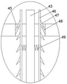
Beneficially, gear selection device is including communicating the setting and being in slide 45 in the inner wall of transmission chamber 44 upper end, be equipped with the locating piece 48 of longitudinal symmetry in the slide 45, sliding connection has feed bar 43 in the slide 45, feed bar 43 lower extreme end is equipped with locking piece 42, be equipped with in the locking piece 42 with the locked groove 41 of push rod 39 butt, sliding connection has the screens pole 46 of longitudinal symmetry in the slide 45, screens pole 46 with feed bar 43 is connected with reset spring 49 between being close to each other, centre of symmetry side fixedly connected with fixture block 47 of locating piece 48 butt is kept away from to screens pole 46.
In the initial state of the device of the invention, the fixture block 47 is abutted against the positioning block 48 and the feeding rod 43 is positioned at the end closest to the transmission cavity 44, so that the distance between the push rod 39 and the stress plate 37 reaches the minimum value and the restraining spring 38 accumulates power potential energy, and at the moment, the turnover plate 10 is horizontally placed at the front end of the switch box 30.
When the device works, the rotary knob 11 is abutted with the screw rod 16 through the ball 13, the square-shaped tube 15 rotates to repeatedly enable the shaft sleeve 14 to move upwards stably and adjust to the width suitable for the mobile phone, the connecting rod 54 is pressed to move towards each other, the filling block 55 is pushed to contract inwards to be separated from the abutment with the limiting column 20, the fine adjustment block 19 is slid to the length suitable for the mobile phone, the connecting rod 54 is released, the filling block 55 moves outwards again through the elastic recovery of the stopping spring 53 and abuts against the clamping column 20, the adjusting rod 21 abuts against four corners of the mobile phone to push the limiting column 20 to press the fine adjustment spring 23, the fine adjustment is carried out, the clamping rod 46 is pressed to pull the feed rod 43 to enable the locking block 42 to move upwards, the suppressing spring 38 is elastically restored to push the push rod 39 to move forwards through the radian change of the locking groove 41, the push rod 39 pushes the ball 24 to move forwards and enable the compression spring 25 to accumulate power, meanwhile, the abutting of the top rod 27 and the arc plate 26 pushes the turnover plate 10 to turn over along the connecting plate 29, the clamping rod 46 is released after a proper angle, the clamping block 47 abuts against the positioning block 48, the angle is locked, meanwhile, the roller 35 is pushed through the rotating rod 40, and the buffer frame 33 is ejected out of the hidden groove 31 through the sliding rod 34.
After the device finishes working, the clamping rod 46 is pressed to push inwards until the turnover plate 10 is leveled again, the connecting rod 54 is pressed, the filling block 55 is separated from being abutted with the limiting column 20, the fine adjustment block 19 slides out, and the mobile phone is taken out.
The invention has the beneficial effects that: the mobile phone length and width distance measuring device is simple in structure and convenient to operate, changes of different mobile phone sizes are adapted through changes of the length and width distance values, and the usable working range of the device is widened. And a mechanical gear switch is adopted to connect the turning angle, so that multi-angle shape-selectable display and placement are realized, an anti-falling buffer structure is additionally arranged, and the capability of the device for protecting a mobile phone is improved.
In the above manner, a person skilled in the art can make various changes depending on the operation mode within the scope of the present invention.