CN110212599B - Quick charging method, terminal, charger and system - Google Patents
Quick charging method, terminal, charger and system Download PDFInfo
- Publication number
- CN110212599B CN110212599B CN201910426056.6A CN201910426056A CN110212599B CN 110212599 B CN110212599 B CN 110212599B CN 201910426056 A CN201910426056 A CN 201910426056A CN 110212599 B CN110212599 B CN 110212599B
- Authority
- CN
- China
- Prior art keywords
- terminal
- charger
- battery
- charging
- voltage values
- Prior art date
- Legal status (The legal status is an assumption and is not a legal conclusion. Google has not performed a legal analysis and makes no representation as to the accuracy of the status listed.)
- Active
Links
- 238000007600 charging Methods 0.000 title claims abstract description 178
- 238000000034 method Methods 0.000 title claims abstract description 47
- 230000009466 transformation Effects 0.000 claims abstract description 20
- 238000006243 chemical reaction Methods 0.000 claims description 46
- 238000001514 detection method Methods 0.000 claims description 12
- 238000007667 floating Methods 0.000 claims description 10
- 238000012545 processing Methods 0.000 claims description 4
- 230000008569 process Effects 0.000 description 10
- 239000003990 capacitor Substances 0.000 description 8
- 238000010586 diagram Methods 0.000 description 7
- 238000004891 communication Methods 0.000 description 4
- 230000009467 reduction Effects 0.000 description 4
- 230000008878 coupling Effects 0.000 description 3
- 238000010168 coupling process Methods 0.000 description 3
- 238000005859 coupling reaction Methods 0.000 description 3
- 230000006870 function Effects 0.000 description 3
- 238000013459 approach Methods 0.000 description 2
- 230000000295 complement effect Effects 0.000 description 2
- 238000005516 engineering process Methods 0.000 description 2
- 238000010278 pulse charging Methods 0.000 description 2
- 238000006467 substitution reaction Methods 0.000 description 2
- HBBGRARXTFLTSG-UHFFFAOYSA-N Lithium ion Chemical compound [Li+] HBBGRARXTFLTSG-UHFFFAOYSA-N 0.000 description 1
- 238000003491 array Methods 0.000 description 1
- 230000005540 biological transmission Effects 0.000 description 1
- 238000010280 constant potential charging Methods 0.000 description 1
- 238000013461 design Methods 0.000 description 1
- 238000011161 development Methods 0.000 description 1
- 238000007599 discharging Methods 0.000 description 1
- 229910001416 lithium ion Inorganic materials 0.000 description 1
- 230000003287 optical effect Effects 0.000 description 1
- 230000001105 regulatory effect Effects 0.000 description 1
- 238000004904 shortening Methods 0.000 description 1
- 238000011895 specific detection Methods 0.000 description 1
Images


Classifications
-
- H—ELECTRICITY
- H02—GENERATION; CONVERSION OR DISTRIBUTION OF ELECTRIC POWER
- H02J—CIRCUIT ARRANGEMENTS OR SYSTEMS FOR SUPPLYING OR DISTRIBUTING ELECTRIC POWER; SYSTEMS FOR STORING ELECTRIC ENERGY
- H02J7/00—Circuit arrangements for charging or depolarising batteries or for supplying loads from batteries
-
- H02J7/045—
-
- G—PHYSICS
- G01—MEASURING; TESTING
- G01R—MEASURING ELECTRIC VARIABLES; MEASURING MAGNETIC VARIABLES
- G01R31/00—Arrangements for testing electric properties; Arrangements for locating electric faults; Arrangements for electrical testing characterised by what is being tested not provided for elsewhere
- G01R31/36—Arrangements for testing, measuring or monitoring the electrical condition of accumulators or electric batteries, e.g. capacity or state of charge [SoC]
- G01R31/3644—Constructional arrangements
- G01R31/3648—Constructional arrangements comprising digital calculation means, e.g. for performing an algorithm
-
- H—ELECTRICITY
- H01—ELECTRIC ELEMENTS
- H01M—PROCESSES OR MEANS, e.g. BATTERIES, FOR THE DIRECT CONVERSION OF CHEMICAL ENERGY INTO ELECTRICAL ENERGY
- H01M10/00—Secondary cells; Manufacture thereof
- H01M10/42—Methods or arrangements for servicing or maintenance of secondary cells or secondary half-cells
- H01M10/44—Methods for charging or discharging
-
- H—ELECTRICITY
- H02—GENERATION; CONVERSION OR DISTRIBUTION OF ELECTRIC POWER
- H02J—CIRCUIT ARRANGEMENTS OR SYSTEMS FOR SUPPLYING OR DISTRIBUTING ELECTRIC POWER; SYSTEMS FOR STORING ELECTRIC ENERGY
- H02J7/00—Circuit arrangements for charging or depolarising batteries or for supplying loads from batteries
- H02J7/0029—Circuit arrangements for charging or depolarising batteries or for supplying loads from batteries with safety or protection devices or circuits
- H02J7/00302—Overcharge protection
-
- H—ELECTRICITY
- H02—GENERATION; CONVERSION OR DISTRIBUTION OF ELECTRIC POWER
- H02J—CIRCUIT ARRANGEMENTS OR SYSTEMS FOR SUPPLYING OR DISTRIBUTING ELECTRIC POWER; SYSTEMS FOR STORING ELECTRIC ENERGY
- H02J7/00—Circuit arrangements for charging or depolarising batteries or for supplying loads from batteries
- H02J7/0029—Circuit arrangements for charging or depolarising batteries or for supplying loads from batteries with safety or protection devices or circuits
- H02J7/0031—Circuit arrangements for charging or depolarising batteries or for supplying loads from batteries with safety or protection devices or circuits using battery or load disconnect circuits
-
- H—ELECTRICITY
- H02—GENERATION; CONVERSION OR DISTRIBUTION OF ELECTRIC POWER
- H02J—CIRCUIT ARRANGEMENTS OR SYSTEMS FOR SUPPLYING OR DISTRIBUTING ELECTRIC POWER; SYSTEMS FOR STORING ELECTRIC ENERGY
- H02J7/00—Circuit arrangements for charging or depolarising batteries or for supplying loads from batteries
- H02J7/0042—Circuit arrangements for charging or depolarising batteries or for supplying loads from batteries characterised by the mechanical construction
-
- H—ELECTRICITY
- H02—GENERATION; CONVERSION OR DISTRIBUTION OF ELECTRIC POWER
- H02J—CIRCUIT ARRANGEMENTS OR SYSTEMS FOR SUPPLYING OR DISTRIBUTING ELECTRIC POWER; SYSTEMS FOR STORING ELECTRIC ENERGY
- H02J7/00—Circuit arrangements for charging or depolarising batteries or for supplying loads from batteries
- H02J7/0047—Circuit arrangements for charging or depolarising batteries or for supplying loads from batteries with monitoring or indicating devices or circuits
-
- H—ELECTRICITY
- H02—GENERATION; CONVERSION OR DISTRIBUTION OF ELECTRIC POWER
- H02J—CIRCUIT ARRANGEMENTS OR SYSTEMS FOR SUPPLYING OR DISTRIBUTING ELECTRIC POWER; SYSTEMS FOR STORING ELECTRIC ENERGY
- H02J7/00—Circuit arrangements for charging or depolarising batteries or for supplying loads from batteries
- H02J7/007—Regulation of charging or discharging current or voltage
- H02J7/00712—Regulation of charging or discharging current or voltage the cycle being controlled or terminated in response to electric parameters
- H02J7/007182—Regulation of charging or discharging current or voltage the cycle being controlled or terminated in response to electric parameters in response to battery voltage
- H02J7/007184—Regulation of charging or discharging current or voltage the cycle being controlled or terminated in response to electric parameters in response to battery voltage in response to battery voltage gradient
-
- H—ELECTRICITY
- H01—ELECTRIC ELEMENTS
- H01M—PROCESSES OR MEANS, e.g. BATTERIES, FOR THE DIRECT CONVERSION OF CHEMICAL ENERGY INTO ELECTRICAL ENERGY
- H01M10/00—Secondary cells; Manufacture thereof
- H01M10/42—Methods or arrangements for servicing or maintenance of secondary cells or secondary half-cells
- H01M10/425—Structural combination with electronic components, e.g. electronic circuits integrated to the outside of the casing
- H01M10/4257—Smart batteries, e.g. electronic circuits inside the housing of the cells or batteries
-
- H—ELECTRICITY
- H02—GENERATION; CONVERSION OR DISTRIBUTION OF ELECTRIC POWER
- H02J—CIRCUIT ARRANGEMENTS OR SYSTEMS FOR SUPPLYING OR DISTRIBUTING ELECTRIC POWER; SYSTEMS FOR STORING ELECTRIC ENERGY
- H02J2207/00—Indexing scheme relating to details of circuit arrangements for charging or depolarising batteries or for supplying loads from batteries
- H02J2207/20—Charging or discharging characterised by the power electronics converter
-
- H—ELECTRICITY
- H02—GENERATION; CONVERSION OR DISTRIBUTION OF ELECTRIC POWER
- H02J—CIRCUIT ARRANGEMENTS OR SYSTEMS FOR SUPPLYING OR DISTRIBUTING ELECTRIC POWER; SYSTEMS FOR STORING ELECTRIC ENERGY
- H02J7/00—Circuit arrangements for charging or depolarising batteries or for supplying loads from batteries
- H02J7/00032—Circuit arrangements for charging or depolarising batteries or for supplying loads from batteries characterised by data exchange
- H02J7/00034—Charger exchanging data with an electronic device, i.e. telephone, whose internal battery is under charge
-
- Y—GENERAL TAGGING OF NEW TECHNOLOGICAL DEVELOPMENTS; GENERAL TAGGING OF CROSS-SECTIONAL TECHNOLOGIES SPANNING OVER SEVERAL SECTIONS OF THE IPC; TECHNICAL SUBJECTS COVERED BY FORMER USPC CROSS-REFERENCE ART COLLECTIONS [XRACs] AND DIGESTS
- Y02—TECHNOLOGIES OR APPLICATIONS FOR MITIGATION OR ADAPTATION AGAINST CLIMATE CHANGE
- Y02E—REDUCTION OF GREENHOUSE GAS [GHG] EMISSIONS, RELATED TO ENERGY GENERATION, TRANSMISSION OR DISTRIBUTION
- Y02E60/00—Enabling technologies; Technologies with a potential or indirect contribution to GHG emissions mitigation
- Y02E60/10—Energy storage using batteries
Landscapes
- Engineering & Computer Science (AREA)
- Power Engineering (AREA)
- Physics & Mathematics (AREA)
- General Physics & Mathematics (AREA)
- Manufacturing & Machinery (AREA)
- Chemical & Material Sciences (AREA)
- Chemical Kinetics & Catalysis (AREA)
- Electrochemistry (AREA)
- General Chemical & Material Sciences (AREA)
- Charge And Discharge Circuits For Batteries Or The Like (AREA)
- Secondary Cells (AREA)
Abstract
The invention provides a quick charging method, a terminal, a charger and a system. The method comprises the following steps: the terminal sends indication information to a charger connected with the terminal to indicate the charger to adjust the output voltage and current; the terminal converts the output voltage of the charger into 1/K times of output voltage and converts the output current of the charger into K times of output current so that the charging circuits on two sides of the battery charge the battery according to the 1/K times of output voltage and the K times of output current; and K is a transformation coefficient of the terminal fixed transformation ratio transformation unit, and is any real number greater than 1. By implementing the quick charging method provided by the invention, the terminal can be quickly charged.
Description
Technical Field
The present invention relates to charging technologies, and in particular, to a method, an apparatus, and a system for fast charging.
Background
With the development of science and technology, the functions of the terminal become more and more powerful, and a user can work and entertain through the terminal, so that the terminal becomes an indispensable part of people's daily life. However, the endurance of the terminal is limited, requiring the user to constantly charge the terminal.
However, as the capacity of the battery configured in the terminal is larger and the density of the battery is higher and higher, the charging time of the terminal is longer and longer, so that the normal use of the user is seriously affected, and the user experience is poor.
Disclosure of Invention
The embodiment of the invention provides a quick charging method, a terminal, a charger and a system, which can quickly charge the terminal, thereby improving the user experience.
The invention discloses a terminal in a first aspect, which comprises a detection circuit, a conversion circuit, a transmitter, a receiver, a Central Processing Unit (CPU), a charging circuit and a battery;
the detection circuit is used for detecting the voltage values of the positive electrode and the negative electrode of the battery;
the CPU is used for generating indication information according to the positive and negative voltage values of the battery;
the transmitter is used for transmitting the indication information to a charger connected with the terminal so as to indicate the charger to adjust output voltage and output current;
the receiver is used for receiving the output voltage and the output current transmitted by the charger; wherein the receiver is electrically connected with the charger;
the conversion circuit is used for converting the output voltage received by the receiver into 1/K times of output voltage and converting the output current received by the receiver into K times of output current, wherein the conversion circuit is a fixed transformation ratio conversion circuit, a transformation coefficient K is one or more constant values, and K is any real number greater than 1;
and the charging circuit is used for charging the battery according to the 1/K times of output voltage and the K times of output current.
It should be noted that the conversion circuit is a Buck circuit or a switched capacitor conversion circuit.
As described in connection with the first aspect, further,
the CPU is used for comparing the positive and negative voltage values with a first preset threshold value to obtain a comparison result; and generating the indication information according to the comparison result.
With reference to the above description, it should be noted that the CPU is further configured to send a disconnection notification to the receiver when detecting that the voltages of the positive electrode and the negative electrode of the battery reach a second preset threshold;
the receiver is used for disconnecting the electric connection with the charger according to the disconnection notice; the first preset threshold is smaller than or equal to the second preset threshold.
Further, it is noted that the terminal further comprises a memory and a bus system, the processor and the memory being connected via the bus system. The memory is configured to store instructions and the processor is configured to execute the instructions stored in the memory to cause the terminal to perform a fast charge.
The invention discloses a charger in a second aspect, the charger comprises a receiver, a voltage regulation circuit and a current regulation circuit;
the receiver is used for receiving indication information sent by a terminal, wherein the indication information can comprise positive and negative voltage values of a battery in the terminal and K times of the positive and negative voltage values, and K is any real number greater than 1;
the voltage adjusting circuit is used for adjusting the voltage value of the output voltage to K times of the voltage values of the positive electrode and the negative electrode of the battery;
the current adjusting circuit is used for determining a charging mode according to the voltage values of the positive electrode and the negative electrode of the battery, acquiring a current value corresponding to the charging mode, and adjusting output current according to the corresponding current value. The charging mode includes, but is not limited to, a pre-charging mode, a fast-charging mode, and a floating-charging mode.
The third aspect of the present invention also discloses another charger, which includes a receiver, a voltage adjusting circuit, and a current adjusting circuit;
the receiver is used for receiving indication information sent by a terminal, wherein the indication information comprises positive and negative voltage values of a battery in the terminal;
the voltage adjusting circuit is used for adjusting the voltage value of the output voltage to be K times of the voltage values of the positive electrode and the negative electrode of the battery, wherein K is any real number larger than 1 and is a voltage regulating coefficient pre-stored in the charger;
the current adjusting circuit is used for determining a charging mode according to the voltage values of the positive electrode and the negative electrode of the battery, acquiring a current value corresponding to the charging mode, and adjusting output current according to the corresponding current value. The charging mode includes, but is not limited to, a pre-charging mode, a fast-charging mode, and a floating-charging mode.
The invention discloses a system for quick charging in a fourth aspect, which comprises a terminal, a charger and a connecting wire; the terminal is connected with the charger through the connecting wire;
the terminal is used for acquiring positive and negative voltage values of a battery in the terminal;
the terminal is further used for generating indication information according to the positive and negative voltage values of the battery and sending the indication information to the charger;
the charger is used for adjusting the voltage value of the output voltage to K times of the voltage values of the positive electrode and the negative electrode of the battery according to the indication information, wherein K is any real number greater than 1;
the charger is also used for determining a charging mode according to the indication information, acquiring a current value corresponding to the charging mode, and adjusting output current according to the corresponding current value;
the terminal is used for converting the output voltage of the charger into 1/K times of output voltage and converting the output current of the charger into K times of output current so that the charging circuits at two ends of the battery charge the battery according to the 1/K times of output voltage and the K times of output current; and K is a transformation coefficient of the terminal fixed transformation ratio transformation circuit.
With reference to the description of the fourth aspect, the generating, by the terminal, the indication information according to the positive and negative voltage values of the battery includes: the terminal compares the positive and negative voltage values with a first preset threshold value to obtain a comparison result; and generating the indication information according to the comparison result.
With reference to the description of the fourth aspect, when detecting that the voltages of the positive electrode and the negative electrode of the battery reach the second preset threshold, the terminal in the system may disconnect the electrical connection between the terminal and the charger, or may notify the charger to enter a sleep state, so that the charger stops supplying power to the terminal.
It should be noted that the terminal may also actively disconnect the electrical connection with the charger when the battery power reaches a third preset threshold, or notify the charger to enter a sleep state so that the charger stops supplying power to the terminal.
The fifth aspect of the present invention discloses a method for fast charging, which comprises:
detecting positive and negative voltage values of a battery in the terminal;
generating indication information according to the positive and negative voltage values of the battery;
sending the indication information to a charger connected with the terminal to indicate the charger to adjust output voltage and output current according to the voltage values of the positive electrode and the negative electrode of the battery;
the terminal receives the output voltage and the output current transmitted by the charger;
converting the output voltage of the charger into 1/K times of output voltage, and converting the output current of the charger into K times of output current, wherein K is a conversion coefficient of a fixed transformation ratio conversion circuit in the terminal, and K is any real number greater than 1;
and charging the battery according to the 1/K-time output voltage and the K-time output current.
With reference to the description of the fourth aspect, further, the generating, by the terminal, the indication information according to the positive and negative voltage values of the battery includes: the terminal compares the positive and negative voltage values with a first preset threshold value to obtain a comparison result; and generating the indication information according to the comparison result. With reference to the description of the fifth aspect, it should be noted that when the terminal is fully charged or the electric quantity reaches a third preset threshold or the voltage reaches a second preset threshold, the terminal disconnects the electrical connection between the terminal and the charger or notifies the charger to stop charging.
A sixth aspect of the present invention discloses another method of rapid charging, the method comprising:
the method comprises the steps that a charger receives indication information sent by a terminal, wherein the indication information comprises positive and negative voltage values of a battery in the terminal;
the charger adjusts the voltage value of the output voltage to be K times of the voltage values of the positive electrode and the negative electrode of the battery, wherein K is any real number larger than 1 and is a voltage regulation coefficient pre-stored in the charger;
and the charger determines a charging mode according to the voltage values of the positive electrode and the negative electrode of the battery, acquires a current value corresponding to the charging mode, and adjusts the output current according to the corresponding current value.
From the above, the technical scheme of the invention provides a quick charging method, a terminal, a charger and a system; in the technical scheme provided by the invention, the indication information is sent to a charger connected with the terminal to indicate the charger to adjust the output voltage and the output current; the terminal converts the output voltage of the charger into 1/K times of output voltage and converts the output current of the charger into K times of output current, wherein the conversion circuit is a fixed transformation ratio conversion circuit, a conversion coefficient K is a constant value, and K is any real number greater than 1; and a charging circuit in the terminal charges the battery according to the 1/K times of output voltage and the K times of output current. By implementing the technical scheme provided by the invention, the terminal can be charged quickly, so that the user experience is improved.
Drawings
In order to more clearly illustrate the technical solutions of the embodiments of the present invention, the drawings needed to be used in the embodiments of the present invention will be briefly described below, and it is obvious that the drawings described below are only some embodiments of the present invention, and it is obvious for those skilled in the art to obtain other drawings based on these drawings without creative efforts.
Fig. 1 is a schematic diagram of a fast charging system according to an embodiment of the present invention;
fig. 2 is a flowchart of a method for fast charging according to an embodiment of the present invention;
fig. 2a is a flowchart of a method for fast charging according to an embodiment of the present invention;
fig. 3 is a block diagram of a fast charging system according to another embodiment of the present invention;
fig. 3a is a physical structure diagram of a terminal according to another embodiment of the present invention;
FIG. 4 is a Buck circuit diagram provided in accordance with an embodiment of the present invention;
FIG. 5 is a circuit diagram of a switched capacitor converter according to another embodiment of the present invention;
FIG. 6 is a flow chart of a method of providing fast charging according to another embodiment of the present invention;
FIG. 7 is a flow chart of a method of providing fast charging according to another embodiment of the present invention;
FIG. 8 is a flow chart of a method of providing fast charging according to another embodiment of the present invention;
fig. 9 is a schematic diagram of a pulsed charge provided in accordance with another embodiment of the present invention.
Detailed Description
The technical solutions in the embodiments of the present invention will be clearly and completely described below with reference to the drawings in the embodiments of the present invention, and it is obvious that the described embodiments are some, not all, embodiments of the present invention. All other embodiments, which can be obtained by a person skilled in the art without any inventive step based on the embodiments of the present invention, shall fall within the scope of protection of the present invention.
With the continuous and powerful terminal, people have stronger and stronger dependence on the terminal and even do not leave the terminal for a moment. People can communicate, entertain, work and the like through the terminal, so the terminal plays an important role in daily life, and the problem that the power consumption of the terminal is high due to the fact that a large number of applications run for a long time at the same time, and the charging speed is low due to the fact that the battery capacity configured by the terminal is large and high in density, the use of a user is seriously influenced, and the user experience is reduced.
The invention provides a quick charging system (short for quick charging system), which can realize quick charging. Fig. 1 shows a schematic diagram of a quick charging system. The system comprises a terminal 10, a charger 20 and a connecting line 30; the terminal 10 is connected with the charger 20 through a connection line 30;
it should be noted that, as shown in fig. 2, the system performs fast charging through the following process:
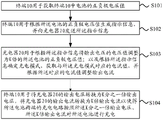
s101, the terminal 10 is used for acquiring positive and negative voltage values of a battery in the terminal 10;
for example, two ends of the battery may be connected in parallel with a detection circuit, so that the voltage values of the positive electrode and the negative electrode of the battery can be obtained at any time.
The terminal can be a mobile phone, a tablet computer, an intelligent wearable device, a computer and other electronic devices.
The battery in the terminal is usually a lithium ion battery, and the type of the battery is not limited herein.
S102, the terminal 10 is used for generating indication information according to the voltage values of the positive electrode and the negative electrode of the battery and sending the indication information to the charger 20;
it is understood that the connection line between the terminal 10 and the charger 20 has a communication function, and information transmission between the terminal 10 and the charger 20 is possible.
It is understood that there are communication lines (both D + and D-lines) between the terminal 10 and the charger 20, in addition to the connection line. The D +, D-lines are each applied with dc voltages of various magnitudes to produce a plurality of combinations of states, each of which may represent a signal. For example, (0V, 0V) represents that the charging current is 0A, (0V, 0.4V) represents 0.5A, (0.4V ) represents 2A, (2.8V ) represents stopping of charging, and the like. Optionally, the D + and D-lines are applied with PWM voltages of duty ratio respectively, and the pulse width represents the signal.
It is understood that the terminal 10 and the charging unit 20 may communicate with each other wirelessly.
S103, the charger 20 is used for adjusting the voltage value of the output voltage to K times of the voltage values of the positive electrode and the negative electrode of the battery according to the indication information; determining a charging mode according to the indication information, acquiring a current value corresponding to the charging mode, and adjusting output current according to the corresponding current value, wherein K is any real number greater than 1;
it is to be understood that, in some embodiments, the indication information includes the positive and negative voltage values V1 of the battery and K times the positive and negative voltage values V2 of the battery, and since K is greater than 1, V2 is greater than V1, the charger directly adjusts the output voltage to K times the positive and negative voltage values V2 of the battery; in other embodiments, the charger determines a charging mode according to the positive and negative voltage values V1 of the battery in the indication information, then obtains a current value corresponding to the charging mode from a memory of the terminal, and adjusts the output current according to the corresponding current value.
It can be understood that, in some embodiments, the indication information includes the positive and negative voltage values V1 of the battery, and the charger pre-stores the voltage regulation coefficient K. Therefore, the charger directly adjusts the output voltage to K times of the voltage value V2 of the positive electrode and the negative electrode of the battery; in other embodiments, the charger determines a charging mode according to the voltage values V1 of the positive and negative electrodes of the battery, then obtains a current value corresponding to the charging mode from a memory of the terminal, and adjusts the output current according to the corresponding current value.
S104, the terminal 10 is used for converting the output voltage of the charger 20 into 1/K times of output voltage, and converting the output current of the charger 20 into K times of output current, so that the charging circuits at two ends of the battery charge the battery according to the 1/K times of output voltage and the K times of output current; and K is a transformation coefficient of the terminal fixed transformation ratio transformation circuit.
It can be understood that, during the charging process, the terminal 10 can obtain the voltages of the positive and negative electrodes of the battery at any time, and adjust the charging current according to the voltage. For example, the terminal 10 compares the acquired voltage value with a first preset threshold value, and acquires a comparison result; and generating indication information according to the comparison result to indicate the charger to adjust the current. Moreover, it should be noted that when the terminal 10 detects that the voltages of the positive and negative electrodes of the battery reach the second preset threshold, the terminal disconnects the electrical connection between the terminal and the charger. The first preset threshold is smaller than or equal to the second preset threshold.
It can be understood that the terminal in the rapid charging system provided by the embodiment of the present invention adopts a direct current/direct current (DC/DC) conversion mode with a fixed transformation ratio, works with a fixed maximum duty ratio, and adjusts the output voltage and the output current of the charger based on the real-time voltage feedback continuity of the battery, thereby effectively improving the charging efficiency of the whole rapid charging system and shortening the rapid charging time.
In another embodiment of the present invention, as shown in fig. 2a, a method for fast charging is provided, which can be applied to the fast charging system described in fig. 1. The method comprises the following steps: setting 3V as a lower limit threshold of a quick charge voltage, setting 4.15V as an upper limit threshold of the quick charge voltage, and setting a conversion coefficient K =2 of a fixed transformation ratio DC/DC conversion module in the terminal;
s201, connecting a terminal with a charger through a connecting wire;
s202, the terminal detects the voltage values of the positive electrode and the negative electrode of the battery in the terminal and sends the voltage values to the charger through the connecting wire;
s203, the charger judges whether the voltage value is larger than 3V;
s204, when the voltage value is less than 3V, the charger starts a pre-charging mode;
wherein, the pre-charging mode is as follows: when the voltage value is less than 3V, the charger adopts low-current pre-charging, the pre-charging current is selected to be 0.2C (the current range can be 0.05-0.5C), and the current value of the pre-charging current can be preset in a factory or can be manually set by a user in the current range; note that 3A is indicated if the battery capacities 3ah,1c are set.
S205, when the voltage value is within the range of 3.0-4.15V, the charger starts a quick charging mode;
wherein, the fast mode of filling does: when the voltage values of the positive electrode and the negative electrode of the battery are within the range of 3.0-4.15V, the charger adopts quick charging, the charger adjusts the charging set current to be 2.0C (the current range can be 0.5C-10C), and the current value of the current can be preset by leaving a factory or can be manually set by a user within the current range; in the fast charging stage, the output voltage of the charger is V1, and V1 is specifically determined according to the real-time feedback voltage vbatt of the battery, specifically, V1= vbatt × 2; the output current of the charger is 2.0C; the mobile phone side converts the voltage V1 and the output current I1 output by the charger through a fixed-ratio DC/DC conversion module, and the output voltage V2= V1/2=V battery and the output current I2=2.0C × 2=4.0C of the conversion circuit.
And S206, when the voltage value is larger than the range of 4.15V, the charger carries out floating charging.
Here, the floating charge may be understood as performing constant voltage charge or low current charge.
When the battery feedback voltage exceeds 4.15V, the charger adjusts the charging current, the charging current range is 0.01C-1.0C, and the current value of the current can be preset in a factory or manually set by a user in the current range.
The structure of the terminal and the charger in the quick charging system according to the embodiment of the present invention will be described in detail below with reference to fig. 3. As shown in fig. 3, the terminal 10 in the rapid charging system includes a detection circuit 110, a conversion circuit 120, a transmitter 130, a battery 140, a Central Processing Unit (CPU) 150, a charging circuit 160, and a receiver 170;
the detection circuit 110 is used for detecting the positive and negative voltage values of the battery 140;
for example, as shown in fig. 3a, in a specific detection circuit for detecting a battery voltage in a mobile phone, a switch Qb is connected in series to a battery, and when the battery voltage is detected, the switch Qb is turned on, and when the battery voltage is detected, the switch Qb is turned off, and the charging and discharging current is completely 0, so that the voltage drop of a circuit and the internal resistance is reduced to the minimum, and Qd is turned on, and the battery voltage is divided by R1R2 and then sent to a rear-end analog-to-digital converter or a comparator, thereby obtaining the battery voltage.
A CPU150 for generating indication information according to the positive and negative voltage values of the battery 140;
a transmitter 130 for transmitting the indication information to the charger 20 connected to the terminal 10 to instruct the charger 20 to adjust the output voltage and the output current;
a receiver 170 for receiving the output voltage and the output current transmitted from the charger; wherein the receiver is electrically connected with the charger;
the conversion circuit 120 is configured to convert an output voltage received by the receiver 170 into a 1/K-fold output voltage, and convert an output current received by the receiver 170 into a K-fold output current, where the conversion circuit 120 is a fixed-transformation-ratio conversion circuit, a conversion coefficient K is one or more constant values, and K is any real number greater than 1;
and the charging circuit 160 is used for charging the battery 140 according to the 1/K times of output voltage and the K times of output current.
Optionally, the conversion circuit is a Buck circuit or switched capacitor conversion.
For example, as shown in fig. 4, the conversion circuit 140 adopts a fixed duty cycle buck mode. Switching tubes Q1 and Q2 in buck with a fixed duty ratio form a bridge arm, the bridge arm is driven by driving signals V1 and V2 to be alternately switched on, direct-current voltage Vin is converted into pulse voltage with the fixed duty ratio, voltage reduction of K times of conversion coefficients is achieved, and direct-current voltage Vout = Vin/K is filtered and output through an inductor L3. By fixing the duty ratio to the maximum value, efficient charging can be performed. In addition, the constant duty buc mode k may be a multiphase buck formed by connecting a plurality of buck in parallel in phase order.
For example, as shown in fig. 5, the DC/DC conversion module may also employ a switched capacitor converter. 4 switching tubes in the switched capacitor converter are connected in series, the middle points of Q1Q2 and Q3Q4 are connected with capacitors C7, V2-V5 are used for driving the switching tubes, wherein V2V5 is complementary, and V3V4 is complementary. 2:1 switched capacitor converter can step down the input voltage to half at a fixed ratio 2:1, vin passing through the converter circuit output Vout ≈ Vin/2. The switch capacitor conversion does not need inductance, and the loss can be obviously reduced, so that the conversion efficiency can be obviously improved, and larger charging current can be realized.
It is understood that the voltage of the battery 140 is continuously increased during the charging process of the terminal 10, so that the charger needs to be continuously informed to adjust the output current; therefore, the CPU150 is further configured to compare the voltage value obtained by the detection circuit 110 with a first preset threshold value to obtain a comparison result; and generating the indication information according to the comparison result. A transmitter 130, configured to transmit the indication information to the charger, where the indication information is used to instruct the charger to adjust an output current. For example, the first preset threshold is 3V, the detection circuit 110 detects the positive and negative voltage values of the battery, the detected positive and negative voltage values are 2.5V, and the cpu150 instructs the charger to charge in a slow charging manner if the positive and negative voltage values are smaller than the first preset threshold; and if the detected voltage value is 3.5V, and the CPU150 judges that the voltage values of the positive electrode and the negative electrode are greater than the first preset threshold value, indicating the charger to charge according to a quick charging mode. The slow charging mode has a corresponding output current (which may be a current value or a range of values). The fast charging mode also has a corresponding output current (which may be a current value or a range of values).
Further, it should be noted that, as time goes by, the electric quantity in the battery 140 is accumulated, and then the detection circuit 110 detects the electric quantity of the battery 140 to determine whether the electric quantity of the battery 140 is fully charged. Therefore, the CPU150 is also configured to send a notification of disconnection to the receiver 170 when detecting that the voltage of the battery 140 reaches the second preset threshold; a receiver 170 for disconnecting the electrical connection with the charger according to the disconnection notification. Alternatively, when detecting that the voltage of the battery 140 reaches the second preset threshold, the CPU150 may further notify the charger 20 to enter a sleep state to stop the charger from supplying power.
The detection circuit 110 can also be used to detect the current of the battery 140 and the state of charge of the battery. If the current is too large or the charge is consumed too fast, the detection circuit 110 will send out a prompt on the interface of the terminal.
It should be noted that in the embodiment of the present invention, the terminal 10 may further include a memory 180 and a bus system, and the CPU150 and the memory are connected by the bus system. The memory is for storing instructions and the processor is for executing the instructions stored in the memory such that the terminal 10 performs the method of fast charging. It should be understood that, in the embodiment of the present invention, the CPU150 may also be other general-purpose processors, digital Signal Processors (DSPs), application Specific Integrated Circuits (ASICs), field Programmable Gate Arrays (FPGAs), or other Programmable logic devices, discrete Gate or transistor logic devices, discrete hardware components, and the like. A general purpose processor may be a microprocessor or the processor may be any conventional processor or the like. The memory may include both read-only memory and random access memory, and provides instructions and data to the CPU. The portion of memory may also include non-volatile random access memory. For example, the memory may also store device type information. The bus system may include a power bus, a control bus, a status signal bus, and the like, in addition to the data bus.
As shown in fig. 3, the charger 20 in the quick charging system includes a receiver 210, a voltage regulation circuit 220 and a current regulation circuit 230;
a receiver 210, configured to receive indication information sent by the terminal 10, where the indication information includes positive and negative voltage values of a battery in the terminal 10 and K times of the positive and negative voltage values, where K is any real number greater than 1;
the voltage adjusting circuit 220 is configured to adjust the voltage value of the output voltage to K times of the voltage values of the positive electrode and the negative electrode of the battery;
the current adjusting circuit 230 is configured to determine a charging mode according to positive and negative voltage values of the battery, obtain a current value corresponding to the charging mode, and adjust an output current according to the corresponding current value.
Optionally, the charger is connected to a power supply, and therefore includes an ac/dc conversion module therein, so as to convert ac power provided by the power supply into dc power.
It can be understood that the invention adopts a DC/DC conversion mode with fixed transformation ratio, works with fixed duty ratio, and continuously adjusts the output voltage and the output current of the charger based on the real-time voltage feedback of the battery, the DC/DC conversion mode has higher conversion efficiency, so that the charging current output to the battery at the mobile phone side can be larger, the charging efficiency of the whole quick charging system is effectively improved, and the quick charging time is effectively shortened.
For the quick charging system in fig. 1, an embodiment of the present invention further provides a charging method. The method includes a terminal side method and a charger side method.
As shown in fig. 6, the method for fast charging at the terminal side includes:
s301, the terminal 10 detects the voltage values of the positive electrode and the negative electrode of the battery in the terminal 10;
s302, the terminal 10 generates indication information according to the voltage values of the positive electrode and the negative electrode of the battery, and sends the indication information to a charger connected with the terminal 10 to indicate the charger 20 to adjust output voltage and output current;
s303, converting the output voltage of the charger into 1/K times of output voltage by the terminal 10, and converting the output current of the charger 20 into K times of output current, wherein K is a conversion coefficient of a fixed transformation ratio conversion circuit in the terminal 10, and K is any real number greater than 1;
and S304, the terminal 10 charges the battery according to the 1/K-time output voltage and the K-time output current.
It will be appreciated that during rapid charging, the positive and negative voltages of the battery of the terminal 10 are constantly changing, and different voltage ranges should be charged with different currents, and therefore,
the terminal generates indication information according to the positive and negative voltage values of the battery, and the indication information comprises the following steps:
the terminal compares the positive and negative voltage values with a first preset threshold value to obtain a comparison result; and generating the indication information according to the comparison result. Further, it should be noted that the terminal 10 continuously detects whether the battery is fully charged, and when the battery is fully charged, the charger 20 needs to be notified to stop charging or to disconnect the electrical connection with the charger 20. Optionally, the terminal 20 may detect whether the voltages of the positive and negative electrodes of the battery reach a second preset threshold, and when detecting that the voltages of the positive and negative electrodes of the battery reach the second preset threshold, disconnect the electrical connection between the terminal and the charger.
As shown in fig. 7, the method for fast charging on the charger 20 side includes:
s401, the charger 20 receives indication information sent by the terminal, wherein the indication information comprises positive and negative voltage values of a battery in the terminal 10;
s402, the charger 20 adjusts the voltage value of the output voltage to be K times of the voltage values of the positive electrode and the negative electrode of the battery, wherein K is any real number larger than 1 and is a voltage regulation coefficient pre-stored in the charger;
s403, the charger 20 determines a charging mode according to the voltage values of the positive electrode and the negative electrode of the battery, obtains a current value corresponding to the charging mode, and adjusts output current according to the corresponding current value.
As shown in fig. 8, the method for fast charging on the charger 20 side further includes:
s501, the charger 20 receives indication information sent by the terminal 10, wherein the indication information comprises positive and negative voltage values of a battery in the terminal 10 and K times of the positive and negative voltage values, and K is any real number greater than 1;
s502, the charger 20 adjusts the voltage value of the output voltage to K times of the voltage values of the positive electrode and the negative electrode of the battery;
s503, the charger 20 determines a charging mode according to the voltage values of the positive electrode and the negative electrode of the battery, obtains a current value corresponding to the charging mode, and adjusts the output current according to the corresponding current value.
It can be understood that the invention adopts a DC/DC conversion mode with fixed transformation ratio, works with fixed duty ratio, and continuously adjusts the output voltage and the output current of the charger based on the real-time voltage feedback of the battery, the DC/DC conversion mode has higher conversion efficiency, so that the charging current output to the battery at the mobile phone side can be larger, the charging efficiency of the whole quick charging system is effectively improved, and the quick charging time is shortened.
In another embodiment of the present invention, a charger and a mobile phone are illustrated.
1) The charger is connected with the mobile phone;
2) Detecting the battery voltage inside the mobile phone to obtain a voltage value V, and sending 2V to the charger through a data line, or sending 2V to the charger through a wireless network (assuming that a conversion coefficient K =2 of a fixed transformation ratio conversion circuit inside the mobile phone);
3) After receiving the voltage information, the charger firstly adjusts the output voltage to 2V or 2V (1+x%) so as to prevent the battery from reversely flowing current to the input end; wherein, the value range of x is 1 to 10;
4) The charger informs the mobile phone of enabling charging;
5) The charger judges whether quick charging can be carried out or not; for example, if the battery voltage is only 2.7V, the current is adjusted to be a small current, the small current pre-charging is carried out until the battery voltage reaches 3V, then the charger adjusts the current to be 4A, and the terminal carries out quick charging according to 8A according to the conversion coefficient.
6) In the charging process of the mobile phone, every preset time, the battery voltage is detected, whether the charger is informed to adjust the current is judged according to the battery voltage, and the charging can be stopped or the charging current can be reduced by detecting the battery voltage instantly.
For example, when the battery voltage approaches 4.2V (e.g., reaches 4.15V), the mobile phone notifies the charger to enter a low current charging state or a constant voltage charging state, and when the battery voltage reaches 4.2V, the charging is stopped. During rapid charging, the current may decrease as the battery voltage increases. The reduction may be a step reduction or a continuous reduction. The charging process may be a continuous pulse charging process, in addition to a continuous dc charging process.
7) After stopping charging, one of the following states may be entered:
A. the charger no longer provides current for the mobile phone, the working current of the mobile phone is provided by the battery, and in the state, when the battery discharges to a certain extent, for example, the voltage drops to 4.1v, the charging is recovered;
B. the charger supplies operating current to the handset, but the path to charge the battery is cut off and no charging current is supplied to the battery, in which case the battery does not supply power to the handset and remains in a fully charged state until the charger and handset are disconnected.
In another fast charging embodiment of the present invention, a specific implementation of pulse charging is provided. As shown in fig. 9, the upper half of fig. 9 is a pulse current waveform, and the lower half is a waveform in which the battery voltage is stepped up. Wherein the abscissa is time and the ordinate is charging current.
During Ton, the charging current is a relatively large value, and the battery voltage rises;
during Toff, the current is 0 or a relatively small value and the cell voltage drops back. During Toff, the battery voltage may be detected.
The current value during Ton may also be varied according to the battery voltage, for example, initially, the battery voltage is 3V, the Ton current is 8A, when the battery voltage reaches 4.0V, it is reduced to 6A, when the battery voltage reaches 4.15V, it is reduced to 3A until full charge.
The duration of Toff may vary, for example, as the battery reaches 4.2V, toff becomes longer as the battery approaches full charge. This growing process can be achieved by detecting the battery voltage.
For example, after a charge pulse, the battery voltage must slightly exceed 4.2V, and then the pulse ends, the battery voltage begins to fall back, and when it falls back to 4.18V, it comes another pulse. The battery is charged more and more, and the time for the voltage to fall back to 4.18V is necessarily longer and longer. When long enough, the battery is considered to be fully charged, and the electrical connection of the terminal to the charger can be interrupted.
Those of ordinary skill in the art will appreciate that the various illustrative elements and algorithm steps described in connection with the embodiments disclosed herein may be implemented as electronic hardware, or combinations of computer software and electronic hardware. Whether such functionality is implemented as hardware or software depends upon the particular application and design constraints imposed on the implementation. Skilled artisans may implement the described functionality in varying ways for each particular application, but such implementation decisions should not be interpreted as causing a departure from the scope of the present invention.
It is clear to those skilled in the art that, for convenience and brevity of description, the specific working processes of the above-described systems, apparatuses and units may refer to the corresponding processes in the foregoing method embodiments, and are not described herein again.
In the several embodiments provided in the present application, it should be understood that the disclosed system, apparatus and method may be implemented in other ways. For example, the above-described apparatus embodiments are merely illustrative, and for example, the division of the units is only one logical division, and other divisions may be realized in practice, for example, a plurality of units or components may be combined or integrated into another system, or some features may be omitted, or not executed. In addition, the shown or discussed mutual coupling or direct coupling or communication connection may be an indirect coupling or communication connection through some interfaces, devices or units, and may be in an electrical, mechanical or other form.
The units described as separate parts may or may not be physically separate, and parts displayed as units may or may not be physical units, may be located in one place, or may be distributed on a plurality of network units. Some or all of the units can be selected according to actual needs to achieve the purpose of the solution of the embodiment.
In addition, functional units in the embodiments of the present invention may be integrated into one processing unit, or each unit may exist alone physically, or two or more units are integrated into one unit.
The functions, if implemented in the form of software functional units and sold or used as a stand-alone product, may be stored in a computer readable storage medium. Based on such understanding, the technical solution of the present invention may be embodied in the form of a software product, which is stored in a storage medium and includes instructions for causing a computer device (which may be a personal computer, a server, or a network device) to execute all or part of the steps of the method according to the embodiments of the present invention. And the aforementioned storage medium includes: a U-disk, a removable hard disk, a Read-Only Memory (ROM), a Random Access Memory (RAM), a magnetic disk or an optical disk, and other various media capable of storing program codes.
The above description is only for the specific embodiments of the present invention, but the scope of the present invention is not limited thereto, and any person skilled in the art can easily conceive of the changes or substitutions within the technical scope of the present invention, and all the changes or substitutions should be covered within the scope of the present invention. Therefore, the protection scope of the present invention shall be subject to the protection scope of the appended claims.
Claims (18)
1. A fast charging system, comprising a terminal, and a charger for charging the terminal;
the terminal is used for acquiring positive and negative voltage values of a battery in the terminal;
the terminal is further used for generating indication information according to the positive and negative voltage values of the battery and sending the indication information to the charger;
the charger is used for determining a charging mode according to the indication information and outputting a current value or a voltage value corresponding to the charging mode;
the terminal is used for converting the output voltage of the charger into 1/K time voltage, wherein the 1/K time voltage is larger than the voltage values of the positive electrode and the negative electrode of the battery, and converting the output current of the charger into K time current so that the charging circuits at two ends of the battery charge the battery according to the 1/K time voltage and the K time current; wherein K is any real number greater than 1.
2. The system of claim 1, wherein the charger, configured to determine a charging mode according to the indication information, comprises:
and the charger determines a charging mode according to the positive and negative voltage values V1 of the battery in the indication information, then acquires a current value corresponding to the charging mode from a memory of the terminal, and outputs current according to the corresponding current value.
3. The system according to claim 1 or 2, wherein the terminal generates indication information according to the positive and negative voltage values of the battery, including:
the terminal compares the positive and negative voltage values with a first preset threshold value to obtain a comparison result; and generating the indication information according to the comparison result.
4. The system according to claim 1 or 2, wherein the terminal generates indication information according to the positive and negative voltage values of the battery, including:
when the voltage values of the positive electrode and the negative electrode are less than 3V, indicating the charger to start a pre-charging mode, wherein the charging current in the pre-charging mode is 0.6 ampere;
and when the voltage values of the positive electrode and the negative electrode are within the range of 3.0-4.15V, indicating the charger to start a quick charging mode, wherein the charging current in the quick charging mode is 1.5-30 amperes.
5. The system according to claim 1 or 2,
and when the terminal detects that the voltages of the positive electrode and the negative electrode of the battery reach a second preset threshold value, the terminal disconnects the electric connection between the terminal and the charger.
6. The system according to claim 4 or 5, wherein the terminal generates indication information according to the positive and negative voltage values of the battery, including:
and when the voltage values of the anode and the cathode are more than 4.15V, indicating the charger to carry out floating charging, wherein the charging current under the floating charging is 0.03-3 amperes.
7. A method of fast charging, the method comprising:
the terminal detects the positive and negative voltage values of a battery in the terminal;
the terminal generates indication information according to the positive and negative voltage values of the battery;
the terminal sends the indication information to a charger connected with the terminal so that the charger can determine output voltage and output current;
the terminal receives the output voltage and the output current transmitted by the charger;
the terminal converts the output voltage of the charger into 1/K time voltage and converts the output current of the charger into K time current, wherein K is a conversion coefficient of a conversion circuit in the terminal, and K is any real number greater than 1;
and the terminal charges the battery by using the voltage which is 1/K times and the current which is K times.
8. The method according to claim 7, wherein the terminal generates indication information according to the positive and negative voltage values of the battery, and comprises:
and the terminal instructs the charger to selectively start one of a pre-charging mode, a quick charging mode or a floating charging mode according to the positive and negative voltage values of the battery.
9. The method according to claim 7 or 8, wherein the terminal generates indication information according to the positive and negative voltage values of the battery, and comprises:
the terminal compares the positive and negative voltage values with a first preset threshold value to obtain a comparison result; and generating the indication information according to the comparison result.
10. The method according to claim 7 or 8,
and when detecting that the voltages of the positive electrode and the negative electrode of the battery reach a second preset threshold value, the terminal disconnects the electric connection between the terminal and the charger.
11. The method according to claim 7 or 8, wherein the terminal generates indication information according to the positive and negative voltage values of the battery, and comprises:
when the voltage values of the positive electrode and the negative electrode are less than 3V, indicating the charger to start a pre-charging mode, wherein the charging current in the pre-charging mode is 0.6 ampere;
and when the voltage values of the positive electrode and the negative electrode are within the range of 3.0-4.15V, indicating the charger to start a quick charging mode, wherein the charging current in the quick charging mode is 1.5-30 amperes.
12. The method according to claim 7 or 8, wherein the terminal generates indication information according to the positive and negative voltage values of the battery, and comprises:
and when the voltage values of the positive electrode and the negative electrode are more than 4.15V, indicating the charger to carry out floating charging, wherein the charging current under the floating charging is 0.03-3 amperes.
13. A terminal, characterized in that the terminal comprises a detection circuit, a conversion circuit, a transmitter, a receiver, a central processing unit CPU, a charging circuit and a battery;
the detection circuit is used for detecting the voltage values of the positive electrode and the negative electrode of the battery;
the CPU is used for generating indication information according to the positive and negative voltage values of the battery;
the transmitter is used for transmitting the indication information to a charger connected with the terminal so that the charger determines an output voltage and an output current;
the receiver is used for receiving the output voltage and the output current transmitted by the charger; wherein the receiver is electrically connected with the charger;
the conversion circuit is used for converting the output voltage received by the receiver into 1/K time voltage and converting the output current received by the receiver into K time current, wherein the conversion circuit is a fixed transformation ratio conversion circuit, and K is any real number greater than 1;
the charging circuit is used for charging the battery by using the 1/K times voltage and the K times current.
14. The terminal of claim 13, wherein the CPU generates the indication information according to the positive and negative voltage values of the battery, including:
and the CPU instructs the charger to selectively start one of a pre-charging mode, a quick charging mode or a floating charging mode according to the positive and negative voltage values of the battery.
15. The terminal according to claim 13 or 14,
the CPU is used for comparing the positive and negative voltage values with a first preset threshold value to obtain a comparison result; and generating the indication information according to the comparison result.
16. The terminal according to claim 13 or 14, wherein the CPU generates indication information according to the positive and negative voltage values of the battery, including:
when the voltage values of the positive electrode and the negative electrode are less than 3V, indicating the charger to start a pre-charging mode, wherein the charging current in the pre-charging mode is 0.6 ampere;
and when the voltage values of the positive electrode and the negative electrode are within the range of 3.0-4.15V, indicating the charger to start a quick charging mode, wherein the charging current in the quick charging mode is 1.5-30 amperes.
17. The terminal according to claim 13 or 14, wherein the CPU generates indication information according to the positive and negative voltage values of the battery, including:
and when the voltage values of the positive electrode and the negative electrode are more than 4.15V, indicating the charger to carry out floating charging, wherein the charging current under the floating charging is 0.03-3 amperes.
18. The terminal according to claim 13 or 14,
the CPU is further used for sending a disconnection notice to the receiver when detecting that the voltage values of the positive electrode and the negative electrode of the battery reach a second preset threshold value;
the receiver is used for disconnecting the electric connection with the charger according to the disconnection notice.
Priority Applications (1)
| Application Number | Priority Date | Filing Date | Title |
|---|---|---|---|
| CN201910426056.6A CN110212599B (en) | 2016-04-08 | 2016-04-08 | Quick charging method, terminal, charger and system |
Applications Claiming Priority (2)
| Application Number | Priority Date | Filing Date | Title |
|---|---|---|---|
| CN201910426056.6A CN110212599B (en) | 2016-04-08 | 2016-04-08 | Quick charging method, terminal, charger and system |
| CN201610218184.8A CN107231012B (en) | 2016-04-08 | 2016-04-08 | A kind of method of quick charge, terminal, charger and system |
Related Parent Applications (1)
| Application Number | Title | Priority Date | Filing Date |
|---|---|---|---|
| CN201610218184.8A Division CN107231012B (en) | 2016-04-08 | 2016-04-08 | A kind of method of quick charge, terminal, charger and system |
Publications (2)
| Publication Number | Publication Date |
|---|---|
| CN110212599A CN110212599A (en) | 2019-09-06 |
| CN110212599B true CN110212599B (en) | 2022-12-27 |
Family
ID=59932828
Family Applications (3)
| Application Number | Title | Priority Date | Filing Date |
|---|---|---|---|
| CN201910425330.8A Active CN110289668B (en) | 2016-04-08 | 2016-04-08 | Quick charging method, terminal, charger and system |
| CN201610218184.8A Active CN107231012B (en) | 2016-04-08 | 2016-04-08 | A kind of method of quick charge, terminal, charger and system |
| CN201910426056.6A Active CN110212599B (en) | 2016-04-08 | 2016-04-08 | Quick charging method, terminal, charger and system |
Family Applications Before (2)
| Application Number | Title | Priority Date | Filing Date |
|---|---|---|---|
| CN201910425330.8A Active CN110289668B (en) | 2016-04-08 | 2016-04-08 | Quick charging method, terminal, charger and system |
| CN201610218184.8A Active CN107231012B (en) | 2016-04-08 | 2016-04-08 | A kind of method of quick charge, terminal, charger and system |
Country Status (8)
| Country | Link |
|---|---|
| US (3) | US10734830B2 (en) |
| EP (3) | EP3654487B1 (en) |
| JP (1) | JP6669931B2 (en) |
| KR (1) | KR102220839B1 (en) |
| CN (3) | CN110289668B (en) |
| DE (1) | DE202017007596U1 (en) |
| ES (2) | ES2793473T3 (en) |
| WO (1) | WO2017173937A1 (en) |
Families Citing this family (12)
| Publication number | Priority date | Publication date | Assignee | Title |
|---|---|---|---|---|
| CN107231013B (en) * | 2016-05-24 | 2019-01-15 | 华为技术有限公司 | A kind of method of charging, terminal, charger and system |
| WO2017206107A1 (en) | 2016-06-01 | 2017-12-07 | 华为技术有限公司 | Charging method and terminal |
| CN108258348B (en) * | 2018-02-13 | 2022-04-29 | 中兴通讯股份有限公司 | Charging method, charging device, charging system, charging circuit, terminal and charging system |
| CN112236923B (en) * | 2018-06-08 | 2024-03-26 | 华为技术有限公司 | Wireless charging device and terminal using same |
| CN108849611A (en) * | 2018-06-14 | 2018-11-23 | 北京北科驿唐科技有限公司 | A kind of electricity saving method and device for Pet loss preventer |
| CN110957773B (en) * | 2019-10-29 | 2022-04-01 | 大族激光科技产业集团股份有限公司 | High-voltage direct-current charging system |
| CN111416408A (en) * | 2020-03-09 | 2020-07-14 | 长兴永烜机械有限公司 | Charger and charging control method thereof |
| CN111509962A (en) * | 2020-05-26 | 2020-08-07 | 深圳市雷能混合集成电路有限公司 | Control method and device for preventing current backflow and power supply equipment |
| TWI740615B (en) * | 2020-08-19 | 2021-09-21 | 僑威科技股份有限公司 | Fast charging device for mobile electronic device |
| CN114079317B (en) * | 2020-08-19 | 2024-02-02 | 广州贵冠科技有限公司 | Quick-charging type charging device of mobile electronic device |
| JP6865879B1 (en) | 2020-09-07 | 2021-04-28 | 日本たばこ産業株式会社 | Aerosol generation system, aspirator controller, and power supply |
| CN112491112A (en) * | 2020-11-18 | 2021-03-12 | 惠州Tcl移动通信有限公司 | Mobile terminal charger and charging method thereof |
Citations (5)
| Publication number | Priority date | Publication date | Assignee | Title |
|---|---|---|---|---|
| CN101874341A (en) * | 2007-08-01 | 2010-10-27 | 英特赛尔美国股份有限公司 | Voltage converter with combined buck converter and capacitive voltage divider |
| CN103078372A (en) * | 2012-12-29 | 2013-05-01 | 杭州汇点网络科技有限公司 | Method for charging electric automobile in multi-battery pack mode |
| CN103236568A (en) * | 2013-05-03 | 2013-08-07 | 深圳市中兴移动通信有限公司 | Charging method and charging system |
| CN104600796A (en) * | 2014-12-30 | 2015-05-06 | 惠州Tcl移动通信有限公司 | Quickly-charger mobile terminal, method and system |
| CN104810909A (en) * | 2014-01-28 | 2015-07-29 | 广东欧珀移动通信有限公司 | Quick charge control method and system |
Family Cites Families (38)
| Publication number | Priority date | Publication date | Assignee | Title |
|---|---|---|---|---|
| CA2022802A1 (en) * | 1989-12-05 | 1991-06-06 | Steven E. Koenck | Fast battery charging system and method |
| JP2914259B2 (en) * | 1995-12-14 | 1999-06-28 | 日本電気株式会社 | Portable electronic device and charge control method for portable electronic device |
| JPH11103538A (en) * | 1997-09-27 | 1999-04-13 | My Way Giken Kk | Optical power generating system |
| US7336054B2 (en) * | 1998-08-14 | 2008-02-26 | Milwaukee Electric Tool Corporation | Apparatus and method of activating a microcontroller |
| US6172481B1 (en) | 1999-09-02 | 2001-01-09 | Qualcomm Incorporated | Method and apparatus for rapid charging batteries under sub-optimal interconnect conditions |
| CA2517333C (en) * | 2001-03-01 | 2007-11-27 | Research In Motion Limited | System and method for powering and charging a mobile communication device |
| CA2456608C (en) * | 2003-01-31 | 2009-01-06 | Universidad Tecnica Federico Santa Maria | A system to determine and analyze the dynamic internal load in revolving mills, for mineral grinding |
| US7135836B2 (en) * | 2003-03-28 | 2006-11-14 | Power Designers, Llc | Modular and reconfigurable rapid battery charger |
| US20050096518A1 (en) * | 2003-10-31 | 2005-05-05 | Yu-Hong Chang | Biological test system |
| JP4820257B2 (en) * | 2006-09-28 | 2011-11-24 | パナソニック株式会社 | Boost converter |
| US7937058B2 (en) * | 2006-10-18 | 2011-05-03 | Freescale Semiconductor, Inc. | Controlling the bandwidth of an analog filter |
| US8509290B2 (en) * | 2006-12-21 | 2013-08-13 | Icera Canada ULC | Closed-loop digital power control for a wireless transmitter |
| US8405361B2 (en) | 2007-09-21 | 2013-03-26 | Qualcomm Incorporated | System and method for charging a rechargeable battery |
| US20090174366A1 (en) * | 2008-01-09 | 2009-07-09 | Freescale Semiconductor, Inc. | Multiple Function Switching Regulator for Use in Mobile Electronic Devices |
| US8278871B2 (en) * | 2009-04-03 | 2012-10-02 | Medtronic, Inc. | Open-loop recharge for an implantable medical device |
| KR101576182B1 (en) * | 2009-05-28 | 2015-12-10 | 삼성전자주식회사 | Method and apparatus for charge control of a portable terminal having solar battery |
| TWM385858U (en) * | 2010-02-12 | 2010-08-01 | Fu Da Tong Technology Co Ltd | Frequency conversion type wireless power supply and charging device |
| GB2484773B (en) * | 2010-10-21 | 2013-09-11 | Chervon Hk Ltd | Battery charging system having multiple charging modes |
| DE102012101769A1 (en) * | 2012-03-02 | 2013-09-05 | Phoenix Contact Gmbh & Co. Kg | Control module for an electrical energy storage, energy storage unit with such a control module, uninterruptible power supply device and method for operating a control module |
| CN102769156B (en) | 2012-07-17 | 2015-04-22 | 广东欧珀移动通信有限公司 | Quick charging method |
| JP5955714B2 (en) * | 2012-09-18 | 2016-07-20 | 株式会社東芝 | Battery pack and electric vehicle |
| WO2014077978A1 (en) | 2012-11-14 | 2014-05-22 | Apple Inc. | High voltage charging for a portable device |
| CN103107575B (en) * | 2013-01-18 | 2015-07-29 | 华为终端有限公司 | Charging method, mobile device, charging device and charging system |
| KR20140120699A (en) * | 2013-04-04 | 2014-10-14 | 삼성전자주식회사 | Control Method for Charging and Electronic Device, and Charging Device supporting the same |
| CN104321960B (en) | 2013-04-22 | 2017-09-22 | 联发科技股份有限公司 | Switch mode charger for charging system |
| US9590436B2 (en) | 2013-05-24 | 2017-03-07 | Qualcomm Incorporated | Master-slave multi-phase charging |
| US9356460B2 (en) | 2013-08-05 | 2016-05-31 | Texas Instruments Incorporated | Method and apparatus of fast battery charging with universal high power input source |
| EP3031119A2 (en) | 2013-09-09 | 2016-06-15 | Apple Inc. | Universal power adapter |
| US9444281B2 (en) | 2014-01-03 | 2016-09-13 | Apple Inc. | Unified high power and low power battery charger |
| CN106253427B (en) | 2014-01-28 | 2018-05-29 | 广东欧珀移动通信有限公司 | Terminal and its battery charging control device and method |
| CN104810873B (en) * | 2014-01-28 | 2018-03-16 | 广东欧珀移动通信有限公司 | Electronic equipment battery charge controller and method |
| CN104810877B (en) * | 2014-01-28 | 2016-12-14 | 广东欧珀移动通信有限公司 | Battery charger and method |
| WO2016024869A1 (en) * | 2014-08-12 | 2016-02-18 | Powerbyproxi Limited | System and method for power transfer |
| CN104505888B (en) | 2014-12-24 | 2016-08-17 | 广东欧珀移动通信有限公司 | A kind of mobile terminal and charging device |
| CN107408448B (en) * | 2014-12-29 | 2019-06-14 | 艾诺格思公司 | System and method for wireless power transmission |
| CN204578156U (en) * | 2015-04-27 | 2015-08-19 | 南通理工学院 | A kind of storage battery charging quickly controller |
| US9748788B2 (en) * | 2015-09-17 | 2017-08-29 | Qualcomm Incorporated | Systems and methods for charging a battery |
| US10734839B2 (en) * | 2017-11-30 | 2020-08-04 | International Business Machines Corporation | Smart meters for monitoring individual and multiple energy consuming devices |
-
2016
- 2016-04-08 CN CN201910425330.8A patent/CN110289668B/en active Active
- 2016-04-08 CN CN201610218184.8A patent/CN107231012B/en active Active
- 2016-04-08 CN CN201910426056.6A patent/CN110212599B/en active Active
-
2017
- 2017-03-24 EP EP19211984.0A patent/EP3654487B1/en active Active
- 2017-03-24 ES ES17778601T patent/ES2793473T3/en active Active
- 2017-03-24 EP EP17778601.9A patent/EP3435511B1/en active Active
- 2017-03-24 DE DE202017007596.2U patent/DE202017007596U1/en active Active
- 2017-03-24 ES ES19211984T patent/ES2951335T3/en active Active
- 2017-03-24 JP JP2019500725A patent/JP6669931B2/en active Active
- 2017-03-24 KR KR1020187029262A patent/KR102220839B1/en active IP Right Grant
- 2017-03-24 WO PCT/CN2017/078098 patent/WO2017173937A1/en active Application Filing
- 2017-03-24 EP EP23157715.6A patent/EP4207552A1/en active Pending
-
2018
- 2018-10-01 US US16/148,305 patent/US10734830B2/en active Active
-
2020
- 2020-07-09 US US16/924,509 patent/US11581745B2/en active Active
-
2023
- 2023-01-18 US US18/156,173 patent/US11990774B2/en active Active
Patent Citations (5)
| Publication number | Priority date | Publication date | Assignee | Title |
|---|---|---|---|---|
| CN101874341A (en) * | 2007-08-01 | 2010-10-27 | 英特赛尔美国股份有限公司 | Voltage converter with combined buck converter and capacitive voltage divider |
| CN103078372A (en) * | 2012-12-29 | 2013-05-01 | 杭州汇点网络科技有限公司 | Method for charging electric automobile in multi-battery pack mode |
| CN103236568A (en) * | 2013-05-03 | 2013-08-07 | 深圳市中兴移动通信有限公司 | Charging method and charging system |
| CN104810909A (en) * | 2014-01-28 | 2015-07-29 | 广东欧珀移动通信有限公司 | Quick charge control method and system |
| CN104600796A (en) * | 2014-12-30 | 2015-05-06 | 惠州Tcl移动通信有限公司 | Quickly-charger mobile terminal, method and system |
Also Published As
| Publication number | Publication date |
|---|---|
| EP4207552A1 (en) | 2023-07-05 |
| EP3435511B1 (en) | 2020-03-04 |
| EP3435511A1 (en) | 2019-01-30 |
| KR20180118786A (en) | 2018-10-31 |
| ES2793473T3 (en) | 2020-11-16 |
| JP2019511197A (en) | 2019-04-18 |
| WO2017173937A1 (en) | 2017-10-12 |
| US20200343756A1 (en) | 2020-10-29 |
| US20230155392A1 (en) | 2023-05-18 |
| CN107231012A (en) | 2017-10-03 |
| DE202017007596U1 (en) | 2023-06-13 |
| US10734830B2 (en) | 2020-08-04 |
| US20190036354A1 (en) | 2019-01-31 |
| CN107231012B (en) | 2019-05-24 |
| EP3435511A4 (en) | 2019-01-30 |
| US11990774B2 (en) | 2024-05-21 |
| US11581745B2 (en) | 2023-02-14 |
| EP3654487B1 (en) | 2023-05-03 |
| CN110212599A (en) | 2019-09-06 |
| CN110289668A (en) | 2019-09-27 |
| JP6669931B2 (en) | 2020-03-18 |
| EP3654487A1 (en) | 2020-05-20 |
| CN110289668B (en) | 2022-03-08 |
| ES2951335T3 (en) | 2023-10-19 |
| KR102220839B1 (en) | 2021-02-25 |
Similar Documents
| Publication | Publication Date | Title |
|---|---|---|
| CN110212599B (en) | Quick charging method, terminal, charger and system | |
| CN113131570B (en) | Battery management circuit, device to be charged and power management method | |
| EP3309924B1 (en) | A terminal with two charging circuits | |
| US10038326B2 (en) | Power bank with charging management including charging interface | |
| CN107894567B (en) | Battery pack and detection system and detection method for interface state of battery pack | |
| US20100314945A1 (en) | Bidirectional converter and electronic device | |
| CN108428951B (en) | Control device, balance correction device, power storage system, and power storage device | |
| CN1741345B (en) | Power management system | |
| CN105429279B (en) | A kind of electric power system of electrical equipment and its method being powered | |
| EP2747238A2 (en) | Balancing of battery cells connected in parallel | |
| JP2015050842A (en) | Power storage system, power storage controller and power storage control method | |
| CN103746425A (en) | Mobile power supply circuit and method thereof | |
| CN102573211A (en) | System, control circuit and method for supplying electric power to LED light source | |
| JPWO2015075854A1 (en) | DC power supply | |
| CN101986502A (en) | Mobile phone battery charging circuit | |
| CN112072766A (en) | Charging device | |
| CN107733000B (en) | Charging method and charger | |
| US20240072574A1 (en) | Wireless charging method and apparatus, and storage medium | |
| CN105634050B (en) | Charging system and control method thereof | |
| CN110707945A (en) | Rectifier circuit, wireless charging device, power supply equipment and wireless charging system | |
| JP2009219336A (en) | Dc power system and its charging method | |
| CA2817315C (en) | Asymmetric series power packs with efficient dc-dc conversion | |
| CN106712130A (en) | Novel charging control system and method | |
| CN115549223A (en) | Charging control method and charging system capable of tracking maximum efficiency | |
| CN116566008A (en) | Battery circuit and power supply method |
Legal Events
| Date | Code | Title | Description |
|---|---|---|---|
| PB01 | Publication | ||
| PB01 | Publication | ||
| SE01 | Entry into force of request for substantive examination | ||
| SE01 | Entry into force of request for substantive examination | ||
| GR01 | Patent grant | ||
| GR01 | Patent grant |