CN110199144B - Flow path switching valve and method of assembling the same - Google Patents
Flow path switching valve and method of assembling the same Download PDFInfo
- Publication number
- CN110199144B CN110199144B CN201780083704.1A CN201780083704A CN110199144B CN 110199144 B CN110199144 B CN 110199144B CN 201780083704 A CN201780083704 A CN 201780083704A CN 110199144 B CN110199144 B CN 110199144B
- Authority
- CN
- China
- Prior art keywords
- valve
- valve body
- hole
- flow path
- path switching
- Prior art date
- Legal status (The legal status is an assumption and is not a legal conclusion. Google has not performed a legal analysis and makes no representation as to the accuracy of the status listed.)
- Active
Links
Images


Classifications
-
- F—MECHANICAL ENGINEERING; LIGHTING; HEATING; WEAPONS; BLASTING
- F16—ENGINEERING ELEMENTS AND UNITS; GENERAL MEASURES FOR PRODUCING AND MAINTAINING EFFECTIVE FUNCTIONING OF MACHINES OR INSTALLATIONS; THERMAL INSULATION IN GENERAL
- F16K—VALVES; TAPS; COCKS; ACTUATING-FLOATS; DEVICES FOR VENTING OR AERATING
- F16K11/00—Multiple-way valves, e.g. mixing valves; Pipe fittings incorporating such valves
- F16K11/02—Multiple-way valves, e.g. mixing valves; Pipe fittings incorporating such valves with all movable sealing faces moving as one unit
- F16K11/08—Multiple-way valves, e.g. mixing valves; Pipe fittings incorporating such valves with all movable sealing faces moving as one unit comprising only taps or cocks
- F16K11/087—Multiple-way valves, e.g. mixing valves; Pipe fittings incorporating such valves with all movable sealing faces moving as one unit comprising only taps or cocks with spherical plug
- F16K11/0873—Multiple-way valves, e.g. mixing valves; Pipe fittings incorporating such valves with all movable sealing faces moving as one unit comprising only taps or cocks with spherical plug the plug being only rotatable around one spindle
- F16K11/0876—Multiple-way valves, e.g. mixing valves; Pipe fittings incorporating such valves with all movable sealing faces moving as one unit comprising only taps or cocks with spherical plug the plug being only rotatable around one spindle one connecting conduit having the same axis as the spindle
-
- F—MECHANICAL ENGINEERING; LIGHTING; HEATING; WEAPONS; BLASTING
- F16—ENGINEERING ELEMENTS AND UNITS; GENERAL MEASURES FOR PRODUCING AND MAINTAINING EFFECTIVE FUNCTIONING OF MACHINES OR INSTALLATIONS; THERMAL INSULATION IN GENERAL
- F16K—VALVES; TAPS; COCKS; ACTUATING-FLOATS; DEVICES FOR VENTING OR AERATING
- F16K31/00—Actuating devices; Operating means; Releasing devices
- F16K31/44—Mechanical actuating means
- F16K31/53—Mechanical actuating means with toothed gearing
- F16K31/535—Mechanical actuating means with toothed gearing for rotating valves
-
- F—MECHANICAL ENGINEERING; LIGHTING; HEATING; WEAPONS; BLASTING
- F16—ENGINEERING ELEMENTS AND UNITS; GENERAL MEASURES FOR PRODUCING AND MAINTAINING EFFECTIVE FUNCTIONING OF MACHINES OR INSTALLATIONS; THERMAL INSULATION IN GENERAL
- F16K—VALVES; TAPS; COCKS; ACTUATING-FLOATS; DEVICES FOR VENTING OR AERATING
- F16K5/00—Plug valves; Taps or cocks comprising only cut-off apparatus having at least one of the sealing faces shaped as a more or less complete surface of a solid of revolution, the opening and closing movement being predominantly rotary
- F16K5/06—Plug valves; Taps or cocks comprising only cut-off apparatus having at least one of the sealing faces shaped as a more or less complete surface of a solid of revolution, the opening and closing movement being predominantly rotary with plugs having spherical surfaces; Packings therefor
- F16K5/0605—Plug valves; Taps or cocks comprising only cut-off apparatus having at least one of the sealing faces shaped as a more or less complete surface of a solid of revolution, the opening and closing movement being predominantly rotary with plugs having spherical surfaces; Packings therefor with particular plug arrangements, e.g. particular shape or built-in means
-
- F—MECHANICAL ENGINEERING; LIGHTING; HEATING; WEAPONS; BLASTING
- F16—ENGINEERING ELEMENTS AND UNITS; GENERAL MEASURES FOR PRODUCING AND MAINTAINING EFFECTIVE FUNCTIONING OF MACHINES OR INSTALLATIONS; THERMAL INSULATION IN GENERAL
- F16K—VALVES; TAPS; COCKS; ACTUATING-FLOATS; DEVICES FOR VENTING OR AERATING
- F16K5/00—Plug valves; Taps or cocks comprising only cut-off apparatus having at least one of the sealing faces shaped as a more or less complete surface of a solid of revolution, the opening and closing movement being predominantly rotary
- F16K5/06—Plug valves; Taps or cocks comprising only cut-off apparatus having at least one of the sealing faces shaped as a more or less complete surface of a solid of revolution, the opening and closing movement being predominantly rotary with plugs having spherical surfaces; Packings therefor
- F16K5/0626—Easy mounting or dismounting means
-
- F—MECHANICAL ENGINEERING; LIGHTING; HEATING; WEAPONS; BLASTING
- F16—ENGINEERING ELEMENTS AND UNITS; GENERAL MEASURES FOR PRODUCING AND MAINTAINING EFFECTIVE FUNCTIONING OF MACHINES OR INSTALLATIONS; THERMAL INSULATION IN GENERAL
- F16K—VALVES; TAPS; COCKS; ACTUATING-FLOATS; DEVICES FOR VENTING OR AERATING
- F16K5/00—Plug valves; Taps or cocks comprising only cut-off apparatus having at least one of the sealing faces shaped as a more or less complete surface of a solid of revolution, the opening and closing movement being predominantly rotary
- F16K5/06—Plug valves; Taps or cocks comprising only cut-off apparatus having at least one of the sealing faces shaped as a more or less complete surface of a solid of revolution, the opening and closing movement being predominantly rotary with plugs having spherical surfaces; Packings therefor
- F16K5/0663—Packings
- F16K5/0694—Spindle sealings
Landscapes
- Engineering & Computer Science (AREA)
- General Engineering & Computer Science (AREA)
- Mechanical Engineering (AREA)
- Multiple-Way Valves (AREA)
- Taps Or Cocks (AREA)
Abstract
Provided are a flow path switching valve and an assembling method thereof, wherein the number of components and the weight can be reduced. A valve shaft (28) coupled to the valve body (20) in order to transmit the rotational force of the rotary drive unit (5) to the valve body (20) is inserted into a vertical through hole (21) that penetrates the valve body (20) in the direction of the axis of rotation (O) (vertical direction) and a fitting hole (13) provided in the valve body (10), a drive gear (9) constituting the rotary drive unit (5) is fixed to an upper coupling unit (28c) protruding from the fitting hole (13), and the valve shaft (28) is rotatably supported by the valve body (10).
Description
Technical Field
The present invention relates to a flow path switching valve and a method of assembling the same, and more particularly, to a rotary flow path switching valve in which a flow path is switched by rotating and sliding a spherical valve body (ball valve body) in a valve chamber.
Background
As such a conventional flow path switching valve, there is known a flow path switching valve (ball valve) including: a valve element (ball valve element) having an inlet passage and an outlet passage and made of an elastic body; a valve chamber for rotatably housing the valve body; and a valve body (valve housing) having an inlet flow path and a plurality of outlet flow paths communicating with the valve chamber, wherein the inlet flow path is always communicated with the inlet flow path, and the outlet flow path is selectively communicated with any one of the plurality of outlet flow paths by a rotation operation of the valve body.
In the conventional flow path switching valve (ball valve) described in patent document 1, the flow path is switched by rotationally driving the valve body via the valve shaft by a motor disposed at an upper portion of the valve body.
Documents of the prior art
Patent document
Patent document 1, Japanese patent laid-open publication No. 2010-223418
Problems to be solved by the invention
In the conventional flow path switching valve as described above, the valve shaft coupled to the valve body is inserted from above through the insertion hole formed in the valve body, and the flange portion formed on the outer periphery of the valve shaft is locked by the upper portion of the valve body and the pressing plate made of metal or the like fixed to the upper portion of the valve body by a screw or the like, whereby the valve shaft is locked so as to be prevented from coming off the valve body.
Therefore, in the conventional flow path switching valve described above, a pressure plate for preventing the valve shaft from coming off and a fixing member (for example, a screw or the like) for fixing the pressure plate to the valve main body are required, and there is a fear that the number of components and the weight are increased.
Disclosure of Invention
The present invention has been made in view of the above circumstances, and an object thereof is to provide a flow path switching valve and an assembling method thereof, which can reduce the number of components and the weight.
Means for solving the problems
In order to solve the above problem, a flow path switching valve according to the present invention includes: a valve body having a valve chamber formed therein and provided with a plurality of ports opening in the valve chamber; a valve body rotatably disposed in the valve chamber and having a flow path formed therein; a sealing member disposed between the valve body and the inlet/outlet, for sealing between the valve body and the inlet/outlet; an elastic member disposed between the seal member and the valve body, the elastic member pressing the seal member against the valve body; and a rotation driving unit that rotates the valve body about a rotation axis, wherein the flow path switching valve rotates the valve body, thereby selectively switching the communication state of the plurality of ports via the flow path of the valve element, characterized in that the valve core is provided with a longitudinal through hole which penetrates the valve core along the direction of the rotation axis, a valve shaft that transmits the rotational force of the rotational driving unit to the valve body is engaged with the vertical through hole so as to be inserted in the rotational axis direction and so as to be relatively non-rotatable, and the valve shaft is inserted into the vertical through hole and an insertion hole provided in the valve body, and a drive gear constituting the rotary drive unit is fixed to a portion protruding from the insertion hole, and the valve shaft is rotatably supported by the valve body, and includes: a lower engaging portion complementary in shape to the longitudinal through hole; an upper connecting portion having a shape smaller than the lower engaging portion and to which the drive gear is fixed; and an intermediate body portion having a shape smaller than the lower engaging portion and connecting the lower engaging portion and the upper engaging portion.
In a preferred embodiment, a stepped portion that abuts and is locked to the periphery of the insertion hole is provided on the outer periphery of the valve shaft.
In another preferred aspect, the valve body has a combined structure of a base member provided with an opening not smaller than an outer shape of the valve body at one end in a rotation axis direction and a holder member coupled and fixed to the opening of the base member.
Further, a method of assembling a flow path switching valve according to the present invention is a method of assembling a flow path switching valve including: a valve body having a valve chamber formed therein and provided with a plurality of ports opening in the valve chamber; a valve body rotatably disposed in the valve chamber and having a flow path formed therein; a sealing member disposed between the valve body and the inlet/outlet, for sealing between the valve body and the inlet/outlet; an elastic member disposed between the seal member and the valve body, the elastic member pressing the seal member against the valve body; and a rotation driving unit that rotates the valve body about a rotation axis, wherein the flow path switching valve selectively switches a communication state of the plurality of ports via the flow path of the valve body by rotating the valve body, and wherein the method for assembling the flow path switching valve comprises the steps of: a valve shaft that is provided with the elastic member, the seal member, and the valve body in the valve chamber, the valve body being provided with a longitudinal through hole that passes through the valve body in the rotation axis direction, and that transmits the rotational force of the rotational driving unit to the valve body, the valve shaft being capable of engaging with the longitudinal through hole so as to be inserted in the rotation axis direction and so as to be relatively non-rotatable; and inserting the valve shaft into the longitudinal through hole, engaging the valve shaft with the longitudinal through hole in a relatively non-rotatable manner, inserting the valve shaft into an insertion hole provided in the valve body, fixing a drive gear constituting the rotation drive unit to a portion of the valve shaft protruding from the insertion hole, and rotatably supporting the valve shaft to the valve body.
In a preferred embodiment, the valve shaft is inserted into the through hole and the fitting hole until a step portion provided on an outer periphery of the valve shaft abuts and is locked to a periphery of the fitting hole.
Effects of the invention
According to the present invention, the valve shaft coupled to the valve body for transmitting the rotational force of the rotary drive unit to the valve body is inserted into the vertical through hole penetrating the valve body in the rotational axis direction (vertical direction) and the insertion hole provided in the valve body, and the drive gear constituting the rotary drive unit is fixed to the portion protruding from the insertion hole, and is rotatably supported by the drive gear with respect to the valve body.
Drawings
Fig. 1 is a perspective view showing an entire configuration of one embodiment of a flow path switching valve (three-way valve) according to the present invention.
Fig. 2 is a partial longitudinal sectional perspective view of the flow path switching valve shown in fig. 1.
Fig. 3A is a perspective view showing the valve body of fig. 2.
Fig. 3B is a perspective view showing a partial cut (a partial cut having a center angle of 90 ° in a plan view) of the valve body of fig. 2.
Fig. 4 is a six-sided view of the valve cartridge of fig. 3A, 3B.
Fig. 5 is a diagram illustrating an assembly process of the flow path switching valve shown in fig. 1 (a process of providing a valve body in a valve chamber).
Fig. 6 is a diagram illustrating an assembly process of the flow path switching valve shown in fig. 1 (a process of supporting and fixing the valve shaft to the valve body).
Fig. 7A is a perspective view showing another example of the valve body of the flow path switching valve shown in fig. 1.
Fig. 7B is a perspective view of a partial cut (a partial cut having a center angle of 90 ° in a plan view) showing another example of the valve body of the flow path switching valve shown in fig. 1.
Fig. 8 is a six-sided view of the valve cartridge of fig. 7A, 7B.
Detailed Description
Hereinafter, embodiments of the present invention will be described with reference to the drawings.
In the drawings, gaps formed between members, separation distances between members, and the like are exaggerated for easy understanding of the invention, and the drawings may be drawn in an exaggerated manner. In the present specification, the description of the position and direction such as up and down, left and right, front and back, etc. is based on the directional arrow in fig. 1 and 2, and does not refer to the position and direction in the actual use state.
(construction/operation of flow channel switching valve 1)
Fig. 1 is a perspective view showing an entire configuration of one embodiment of a flow path switching valve according to the present invention, and fig. 2 is a partial longitudinal sectional perspective view of the flow path switching valve shown in fig. 1. Fig. 3A and 3B are views showing the valve body of fig. 2, fig. 3A is a perspective view, fig. 3B is a perspective view of a partial cut (a partial cut having a center angle of 90 ° in a plan view), and fig. 4 is a six-side view of the valve body of fig. 3A and 3B.
The flow path switching valve 1 of the illustrated embodiment is used as a rotary three-way valve for switching a flow path of a fluid flowing in an engine room of an automobile or the like to multiple directions, and basically includes: a valve body 10 having a valve chamber 11; a spherical valve body (also referred to as a ball valve body) 20 rotatably disposed in the valve chamber 11; a motor 8 disposed from the rear to the upper portion of the valve main body 10 for rotating the valve body 20 about the rotation axis (center line) O; and a rotation driving section 5 constituted by a driving gear 9 and the like. Here, the valve main body 10 is formed integrally with the rotation driving portion 5. The rotation axis (axis extending in the vertical direction) O of the valve body 20 housed in the valve chamber 11 is coaxial with the center line of the inflow port p10 and the valve shaft 28 described later.
The valve body 10 is composed of, for example, a square tubular base member 12 with a ceiling portion 12a made of synthetic resin or metal, and a holder member 15, and the base member 12 forms a horizontally-inclined cylindrical valve chamber 11 therein, and a horizontal outlet port (inlet/outlet) p11 and an outlet port (inlet/outlet) p12 that are open in the valve chamber 11 are provided at the left and right portions thereof, respectively. Ports # 11 and #12 formed of pipe joints are integrally connected to the outer periphery of the base member 12 so as to communicate with the outlet ports p11 and p 12. Further, a fitting hole 13 through which (the intermediate body portion 28b of) the valve shaft 28 coupled to the valve body 20 is inserted is provided in the ceiling portion 12a of the base member 12, and projections 14a and 14b for positioning of annular seal members 31 and 32 (described later) are provided so as to protrude over substantially half of the circumference (downward) of the fitting hole 13 (more specifically, at portions on the left and right sides of the fitting hole 13 from the portion abutting against and locking a step portion 28s between a lower engaging portion 28a of the valve shaft 28 and the intermediate body portion 28b (described later) (see also fig. 5). A bracket member 15 having a port # 10 formed of a pipe joint is fitted and fixed to a lower end opening of the base member 12 by ultrasonic welding, screwing, press-fitting, caulking, or the like (in the illustrated example, ultrasonic welding), and the bracket member 15 is provided with a vertical inflow port (inlet/outlet) p10 that opens in the valve chamber 11.
That is, the valve body 10 is provided with an inlet port p10 that opens at the bottom of the valve chamber 11, and outlet ports (side ports) p11, p12 that open at the side of the valve chamber 11 are provided at an angular interval of 180 ° (in other words, facing each other on the opposite side of the rotation axis O of the valve body 20).
A motor housing portion 16 is integrally formed at a rear portion of the base member 12 of the valve body 10, the motor housing portion 16 houses a motor 8 constituting a rotation driving portion 5 for rotating the valve body 20 (a valve shaft 28 coupled to the valve body 20), a gear housing portion 17 is integrally formed at an upper portion (an upper surface side of the ceiling portion 12 a) of the base member 12 of the valve body 10, and the gear housing portion 17 houses a drive gear 9 or the like coupled to the motor 8 and transmitting a rotational force of the motor 8 to the valve shaft 28.
The valve body 20 is made of, for example, synthetic resin, metal, or the like, and has a flow path (internal flow path) 25 provided therein for selectively communicating with the inlet p10 and the two outlets p11 and p12 provided in the valve body 10, in other words, for selectively switching the communication state of the inlet p10 and the two outlets p11 and p 12.
The internal flow path 25 is formed by a through hole penetrating from the lower portion to the side portion in the valve body 20, and the lower opening thereof is always communicated with the inflow port p10, and the side opening thereof is alternatively communicated with one of the two outflow ports p11 and p 12.
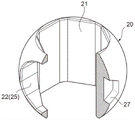
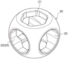
Specifically, as is apparent from fig. 3A and 3B and fig. 4, the valve body 20 is formed with a vertical through hole 21 having a substantially hexagonal cross section (i.e., the upper and lower end portions open in a substantially hexagonal shape) that vertically penetrates the valve body 20 (in the direction of the rotation axis O of the valve body 20), and a lateral hole 22 having a substantially hexagonal cross section that merges from the outer periphery (side portion) of the valve body 20 to the center of the vertical through hole 21 is formed (in the direction orthogonal to the rotation axis O of the valve body 20).
The (lower opening of the) vertical through hole 21 and the inlet port p10 are always communicated, the (side opening of the) horizontal hole 22 is alternatively communicated with one of the two outlet ports p11 and p12, and the internal flow path 25 having an inverted L shape in a side view is formed by the lower half portion of the vertical through hole 21 and the horizontal hole 22 (in the valve body 20).
In addition, hexagonal holes (hexagonal concave holes in side view) 26 and 27 (described in detail later) are provided on the outer periphery (outer peripheral sealing surface) of the valve body 20, specifically, on the back side of the side opening of the lateral hole 22 and the lateral side of the side opening of the lateral hole 22 in the outer periphery of the valve body 20, and the hexagonal holes 26 and 27 serve as rotational engagement portions for rotatably providing the valve body 20 in the valve chamber 11 when assembled.
The stepped valve shaft 28 (the lower portion of the lower engaging portion 28 a) for transmitting the rotational force of the motor 8 to the valve body 20 is coupled to (the upper portion of the vertical through hole 21 of) the valve body 20.
Specifically, as can be seen by referring to fig. 2 and 6 together, the valve shaft 28 is configured from the lower side as follows: a lower engaging portion 28a having a shape complementary to the shape of the longitudinal through hole 21 of the valve body 20 (i.e., a substantially hexagonal cross section) or a shape slightly smaller than the longitudinal through hole 21; an intermediate body 28b having a slightly smaller shape than the lower engaging portion 28a and a circular cross section; an upper coupling portion 28c having an outer diameter substantially the same as that of the intermediate body portion 28b and a substantially hexagonal cross section; and a D-cut convex portion 28D for circumferential positioning provided to protrude from the upper coupling portion 28 c. The lower engaging portion 28a is inserted into the upper opening of the vertical through hole 21, the intermediate body portion 28b is inserted (inserted) into the insertion hole 13 of the valve body 10, and the upper connecting portion 28c protrudes upward from the insertion hole 13 (upward side of the ceiling portion 12 a). Two O-rings 29 as sealing members are interposed between the intermediate body 28b (annular groove formed in the outer periphery of the intermediate body 28b) rotatably inserted into the insertion hole 13.
By fitting the lower engaging portion 28a into the vertical through hole 21, the valve body 20 is engaged with the valve shaft 28 so as not to be relatively rotatable about the rotation axis O, and the valve shaft 28 and the valve body 20 rotate integrally.
Further, a stepped portion 28s formed between the lower engaging portion 28a and the intermediate body portion 28b in the valve shaft 28 abuts and is locked around the fitting hole 13 in the ceiling portion 12a of (the base member 12 of) the valve main body 10, the drive gear 9 of the rotary drive portion 5 is fixed by press-fitting, caulking, or the like to the upper coupling portion 28c protruding from the fitting hole 13, and the ceiling portion 12a of the valve main body 10 is sandwiched between (the upper surface of) the stepped portion 28s and (the lower surface of) the drive gear 9, and the valve shaft 28 is supported so as to be rotatable (immovable up and down) with respect to the valve main body 10.
Further, as described above, since the longitudinal through hole 21 of the valve body 20 is set to be larger than the outer shape of the valve shaft 28, the valve shaft 28 can be inserted in the vertical direction (the rotation axis O direction) through the longitudinal through hole 21 (described in detail later).
Further, O-rings (elastic members) 33, 34 (in a compressed state) as sealing members made of an elastic material such as rubber are interposed between the respective sealing members 31, 32 and (around the respective outlet ports p11, p12 of the valve body 10) (specifically, formed in annular grooves on the left surface (surface on the outlet port p11 side) of the sealing member 31 and the right surface (surface on the outlet port p12 side) of the sealing member 32). By the elastic force (repulsive force) of the O- rings 33 and 34, the valve element 20 and the outlet ports p11 and p12 are hermetically sealed (sealed) by pressing (inner circumferential sealing surfaces of) the sealing members 31 and 32 to (outer circumferential sealing surfaces of) the valve element 20 to the side of (outer circumferential sealing surfaces of) the valve element 20 and bringing the sealing members into close contact with the side of (outer circumferential sealing surfaces of) the valve element 20.
In the flow path switching valve (three-way valve) 1 having this configuration, when the valve body 20 is rotated in the valve chamber 11 by the rotation driving unit 5 including the motor 8, the drive gear 9, and the like, the communication state between the inlet port p10 and the two outlet ports p11 and p12 provided in the valve body 10 is selectively switched by the internal flow path 25 provided in the valve body 20.
Specifically, by rotating the spool 20 by about 180 °, the following two modes are selectively obtained: a mode (first communicating state) in which the inlet port p10 provided at the bottom of the valve body 10 communicates with the outlet port p11 provided at the left portion of the valve body 10 (via the internal flow path 25 constituted by the lower half of the vertical through hole 21 and the lateral hole 22); and a mode (second communication state) in which the inlet port p10 provided at the bottom of the valve body 10 communicates with the outlet port p12 provided at the right of the valve body 10 (via the internal flow path 25 constituted by the lower half of the vertical through hole 21 and the lateral hole 22).
In the first communication state, the opening of the seal member 32 corresponding to the right outlet port p12 is closed by (the outer peripheral sealing surface of) the valve body 20 (here, the portion where the hexagonal hole 26 is formed), the flow path connected to the outlet port p12 is blocked, and the fluid flowing upward from the inlet port p10 passes through the internal flow path 25 of the valve body 20 and flows out only from the left outlet port p 11. On the other hand, in the second communication state, the opening of the seal member 31 corresponding to the left-side outlet port p11 is closed by (the outer peripheral sealing surface of) the valve body 20 (here, the portion where the hexagonal socket 26 is formed), the flow path connected to the outlet port p11 is blocked, and the fluid flowing upward from the inlet port p10 passes through the internal flow path 25 of the valve body 20 and flows out only from the right-side outlet port p 12.
(method of assembling flow path switching valve 1)
The flow path switching valve (three-way valve) 1 having the above-described configuration is assembled, for example, in the following steps. Fig. 5 and 6 are views for explaining an assembly process of the flow path switching valve shown in fig. 1, fig. 5 is a view for explaining a process of disposing a valve body in a valve chamber, and fig. 6 is a view for explaining a process of supporting and fixing a valve shaft to a valve body.
When the flow path switching valve 1 is assembled, as shown in fig. 5, first, the O- rings 33 and 34 are fitted to (the annular grooves of) the respective seal members 31 and 32 (step 1), and before the holder member 15 is assembled to (the lower end opening of) the base member 12 constituting the valve main body 10, the seal members 31 and 32 with the O- rings 33 and 34 are installed inside (i.e., in the valve chamber 11) through the lower end opening of the base member 12 (around the left and right outlet ports p11 and p 12) (step 2). At this time, the projections 14a and 14b provided on the ceiling portion 12a of the base member 12 align the respective sealing members 31 and 32 in the valve chamber 11, and the distance between the sealing members 31 and 32 is equal to or greater than the height of the valve body 20 in the vertical direction (the direction of the rotation axis O) or slightly greater than the height of the valve body 20 in the vertical direction (the direction of the rotation axis O).
Next, the valve body 20 having the internal flow path 25 formed by the vertical through hole 21 and the horizontal hole 22 is disposed inside (specifically, between the sealing members 31 and 32 of the respective outlet ports p11 and p12 disposed in the valve chamber 11) the lower opening (the opening equal to or larger than the outer shape (outer diameter) of the valve body 20) of the base member 12 with the hexagonal hole 26 facing downward while being tilted (that is, while the rotational axis direction of the valve body 20 is set to be horizontal, or while the rotational axis of the valve body 20 is set to be oriented in the left-right direction, that is, while the upper and lower end faces of the valve body 20 are facing the left and right sealing members 31 and 32) (step 3).
In this state, for example, a rotating jig G such as a hexagon wrench having a head portion with a hexagonal cross section at the tip is inserted from the lower opening of the base member 12, and the head portion thereof is fitted into (engaged with) the hexagonal hole (rotation engaging portion) 26 of the valve body 20 to rotate the rotating jig G, whereby the valve body 20 is rotated by about 90 ° between the seal members 31 and 32 in the valve chamber 11 (rotated by about 90 ° counterclockwise as viewed from below about an axis extending in the vertical direction) (step 4). When the valve body 20 rotates, the outer periphery (outer peripheral sealing surface) of the valve body 20 slides toward (inner peripheral sealing surfaces of) the left and right sealing members 31, 32, and the O- rings 33, 34 disposed outside the sealing members 31, 32 are slightly compressed, so that the outer periphery (outer peripheral sealing surface) of the valve body 20 is pressed against (inner peripheral sealing surfaces of) the sealing members 31, 32.
Next, the same rotating jig G as described above is inserted through the right port # 12 of the base member 12, and the head portion thereof is fitted into (engaged with) the hexagonal hole (rotation engaging portion) 27 of the valve body 20 to rotate the rotating jig G, whereby the valve body 20 is rotated by about 90 ° (rotated by about 90 ° in the counterclockwise direction as viewed from the right about the axis extending in the left-right direction) between the seal members 31, 32 in the valve chamber 11 (step 5).
As described above, the valve body 20 is rotated about two axes perpendicular to the rotation axis O between the seal members 31 and 32 in the valve chamber 11, whereby the valve body 20 is set in a posture at the time of use (a posture in which the rotation axis O direction of the valve body 20 is set to a vertical direction, that is, a posture in which the vertical through hole 21 is directed in the vertical direction) in the valve chamber 11.
Next, as shown in fig. 6, the O-ring 29 is attached to the intermediate body portion 28b of the valve shaft 28 (step 6), and the valve shaft 28 is inserted into the vertical through hole 21 of the valve body 20 through the lower opening of the base member 12 in a state where the lower engaging portion 28a of the valve shaft 28 is positionally aligned with the rotational position (angular position around the rotation axis O) of the vertical through hole 21 of the valve body 20 until the stepped portion 28s between the lower engaging portion 28a and the intermediate body portion 28b of the valve shaft 28 abuts against the ceiling portion 12a (around the insertion hole 13 in the base member 12) of the valve body 10. Thereby, (a lower portion of) the lower engaging portion 28a of the valve shaft 28 (in a state of being engaged so as to be relatively non-rotatable about the rotation axis O) is fitted into the upper opening of the through hole 21, the intermediate body portion 28b is inserted into the fitting hole 13 of the valve body 10, and the upper connecting portion 28c protrudes upward from the fitting hole 13 (step 7).
Then, the holder member 15 is attached to the lower opening of the base member 12 by ultrasonic welding, screwing, or the like, and the drive gear 9 of the rotary drive unit 5 is attached to the upper coupling portion 28c of the valve shaft 28 protruding from the insertion hole 13 by press-fitting, caulking, or the like, so that the valve shaft 28 is supported and fixed to the valve body 10 in a rotatable and slip-proof state (step 8). The flow path switching valve 1 is assembled by attaching the motor 8 and the like constituting the rotation driving section 5 to the valve main body 10.
In the flow path switching valve 1, in order to smoothly insert the valve body 20 into the valve chamber 11, the distance between the seal members 31 and 32 disposed in the valve chamber 11 is set to be equal to or greater than the height of the valve body 20 in the vertical direction (the direction of the rotation axis O), but even when the distance between the seal members 31 and 32 is set to be slightly smaller than the height of the valve body 20 in the vertical direction, the distance between the seal members 31 and 32 can be increased by compressing the left and right O- rings 33 and 34 with the seal members 31 and 32 when the valve body 20 is inserted (compressing with a force greater than the compression force applied to the O- rings 33 and 34 in normal use), and the valve body 20 can be disposed between the seal members 31 and 32.
As described above, in the flow path switching valve 1 of the present embodiment, the valve shaft 28 coupled to the valve body 20 to transmit the rotational force of the rotary drive unit 5 to the valve body 20 is inserted into the vertical through hole 21 that penetrates the valve body 20 in the direction of the rotation axis O (vertical direction) and the insertion hole 13 provided in the valve body 10, the drive gear 9 constituting the rotary drive unit 5 is fixed to the upper coupling portion 28c protruding from the insertion hole 13, and the valve shaft 28 is rotatably supported by the drive gear 9 with respect to the valve body 10, so that the number of components and the weight can be reduced as compared with a conventional flow path switching valve using a fixing member such as a pressure plate or a screw, for example.
It is to be noted that the configuration, shape, and the like of the internal flow path 25 formed inside the valve body 20 may be appropriately changed according to the use application and the like of the flow path switching valve 1.
For example, as shown in fig. 7A, 7B and 8, in addition to the vertical through hole 21 and the horizontal hole 22, a transverse through hole 23 having a substantially hexagonal cross section (that is, having a hexagonal side opening) may be formed, and the transverse through hole 23 penetrates the valve body 20 perpendicularly to the rotation axis O and intersects and merges with the vertical through hole 21 and the horizontal hole 22. In this case, the hexagonal hole (rotation engagement portion) 27 is not provided, but (an end opening of) the through hole 23 may be used as the same rotation engagement portion as the hexagonal hole 27. In the example shown in fig. 7A, 7B and 8, the lower opening of the vertical through hole 21 is a circular shape slightly larger than the upper opening of a hexagonal shape in plan view. In the case of using the valve body 20 shown in fig. 7A, 7B, and 8, by rotating the valve body 20 by about 180 °, the following three modes can be selectively obtained: a mode (first communicating state) in which the inflow port p10 provided at the bottom of the valve main body 10 communicates only with the outflow port p11 provided at the left part of the valve main body 10 (via the internal flow path 25 constituted by the lower half of the vertical through hole 21 and the horizontal hole 22); a mode (second communication state) in which both the inlet port p10 provided at the bottom of the valve body 10 and the outlet ports p11 and p12 provided at the left and right of the valve body 10 communicate with each other (via the internal flow path 25 constituted by the lower half of the vertical through-hole 21 and the horizontal through-hole 23); and a mode (third communication state) in which the inflow port p10 provided at the bottom of the valve main body 10 communicates only with the outflow port p12 provided at the right portion of the valve main body 10 (via the internal flow path 25 constituted by the lower half of the vertical through hole 21 and the lateral hole 22).
It is needless to say that both the transverse hole 22 and the transverse through hole 23 are not necessarily provided, and for example, the transverse through hole 23 shown in fig. 7A, 7B, and 8 may be provided instead of the transverse hole 22.
It is to be understood that the cross-sectional shapes of the vertical through-hole 21, the horizontal hole 22, the horizontal through-hole 23, and the hexagonal holes 26 and 27 as the rotational engagement portions formed in the valve body 20 may be appropriately selected. For example, the cross-sectional shapes of the vertical through-holes 21 and the horizontal through-holes 23 may be polygons other than hexagons, ellipses, or the like, and the side openings of the horizontal holes 22 may be polygons other than hexagons, ellipses, circles, or the like. The hexagonal holes 26 and 27 may be polygonal or elliptical holes other than hexagonal holes, as long as the valve body 20 can be rotated in the valve chamber 11 during assembly.
It is to be understood that the number and arrangement of the ports (inlet and outlet ports) formed in the valve body 10 may be appropriately changed according to the application location of the flow path switching valve 1. In the above embodiment, as the flow path switching valve 1, a three-way valve in which the inlet port p10 is opened at the bottom of the valve chamber 11 and the two outlet ports p11 and p12 are opened at an angular interval of 180 ° at the side of the valve chamber 11 has been described as an example, but it is needless to say that, for example, a two-way valve in which the inlet port at the bottom side is omitted and one of the outlet ports at the side is used as the inlet port, or a four-way or more switching valve in which the number and arrangement of the inlet ports and the outlet ports opened in the valve chamber are changed may be used.
The flow path switching valve 1 of the above embodiment is used for switching the flow path in an engine room or the like (an engine cooling circuit, an electronic equipment cooling circuit, or the like) in a vehicle, but may be used for switching the flow path in a hot water supply apparatus, for example.
Description of the reference numerals
1 flow path switching valve
5 Rotary drive part
8 Motor
9 drive gear
10 valve body
11 valve chamber
12 base part
12a ceiling part
13 inserting hole
15 support part
20 valve core
21 longitudinal through hole
22 transverse hole
23 traverse through hole
25 internal flow path
26. 27 hexagonal hole (rotating block part)
28 valve shaft
28a lower engaging part
28b intermediate body portion
28c upper connecting part
28D cut into D-shaped projections
28s step part
29O-shaped ring
31. 32 sealing member
33. 34O shaped ring (elastic component)
p10 inflow (entrance)
p11 outflow (side outlet)
p12 outflow (side outlet)
Claims (4)
1. A flow path switching valve is provided with: a valve body having a valve chamber formed therein and provided with a plurality of ports opening in the valve chamber; a valve body which is rotatably disposed in the valve chamber and has a flow path formed therein; a sealing member disposed between the valve body and the inlet/outlet, for sealing between the valve body and the inlet/outlet; an elastic member disposed between the seal member and the valve body for urging the seal member to the valve element; and a rotation driving portion that rotates the valve body about a rotation axis, the flow path switching valve selectively switching a communication state of the plurality of inlet and outlet ports via the flow path of the valve body by rotating the valve body, the flow path switching valve being characterized in that,
the valve body is provided with a longitudinal through hole which penetrates the valve body in the rotation axis direction and with which a valve shaft which transmits the rotational force of the rotation driving section to the valve body is engaged so as to be able to pass in the rotation axis direction and be unable to rotate relative thereto,
the valve shaft is inserted into the through hole and a fitting hole provided in the valve body, and a drive gear constituting the rotation drive unit is fixed to a portion protruding from the fitting hole, and the valve shaft is rotatably supported by the valve body,
the valve shaft has: a lower engaging portion complementary in shape to the longitudinal through hole; an upper connecting portion having a shape smaller than the lower engaging portion and to which the drive gear is fixed; and an intermediate body portion having a shape smaller than the lower engaging portion and connecting the lower engaging portion and the upper engaging portion,
the periphery of the valve shaft is provided with a step part which is abutted and blocked with the periphery of the embedding hole, and the driving gear and the step part clamp the valve main body.
2. The flow path switching valve according to claim 1, wherein the valve body has a combined structure of a base member provided with an opening not smaller than an outer shape of the valve body at one end in a rotation axis direction, and a holder member coupled and fixed to the opening of the base member.
3. The flow path switching valve according to claim 1 or 2, wherein the valve body is provided with a lateral hole that merges from an outer periphery of the valve body to a center of the vertical through hole, and a back side of a side opening of the lateral hole and a lateral side of the side opening of the lateral hole are provided with a rotational engagement portion that is provided to rotate the valve body in a predetermined direction in the valve chamber.
4. A method for assembling a flow path switching valve, the flow path switching valve comprising: a valve body having a valve chamber formed therein and provided with a plurality of ports opening in the valve chamber; a valve body which is rotatably disposed in the valve chamber and has a flow path formed therein; a sealing member disposed between the valve body and the inlet/outlet, for sealing between the valve body and the inlet/outlet; an elastic member disposed between the seal member and the valve body for urging the seal member to the valve element; and a rotation driving unit that rotates the valve body about a rotation axis, wherein the flow path switching valve selectively switches communication states of the plurality of ports via the flow path of the valve body by rotating the valve body, and wherein the method for assembling the flow path switching valve comprises:
a valve shaft that is provided with the elastic member, the seal member, and the valve body in the valve chamber, the valve body being provided with a longitudinal through hole that passes through the valve body in the rotation axis direction, and that transmits the rotational force of the rotary drive unit to the valve body, the valve shaft being capable of engaging with the longitudinal through hole so as to be inserted in the rotation axis direction and so as to be relatively non-rotatable; and
the valve shaft is inserted into the longitudinal through hole, the valve shaft is engaged with the longitudinal through hole in a relatively non-rotatable manner, the valve shaft is inserted into an insertion hole provided in the valve body from a side opposite to the rotary drive unit in the direction of the rotation axis until a stepped portion provided on the outer periphery of the valve shaft abuts and is locked around the insertion hole, a drive gear constituting the rotary drive unit is fixed to a portion of the valve shaft protruding from the insertion hole, and the valve shaft is rotatably supported by the valve body.
Applications Claiming Priority (3)
| Application Number | Priority Date | Filing Date | Title |
|---|---|---|---|
| JP2017006030A JP6745529B2 (en) | 2017-01-17 | 2017-01-17 | Flow path switching valve and assembling method thereof |
| JP2017-006030 | 2017-01-17 | ||
| PCT/JP2017/040421 WO2018135103A1 (en) | 2017-01-17 | 2017-11-09 | Channel switching valve and method for assembling same |
Publications (2)
| Publication Number | Publication Date |
|---|---|
| CN110199144A CN110199144A (en) | 2019-09-03 |
| CN110199144B true CN110199144B (en) | 2021-03-19 |
Family
ID=62908677
Family Applications (1)
| Application Number | Title | Priority Date | Filing Date |
|---|---|---|---|
| CN201780083704.1A Active CN110199144B (en) | 2017-01-17 | 2017-11-09 | Flow path switching valve and method of assembling the same |
Country Status (6)
| Country | Link |
|---|---|
| US (1) | US11073216B2 (en) |
| EP (1) | EP3572696B1 (en) |
| JP (1) | JP6745529B2 (en) |
| KR (2) | KR102362453B1 (en) |
| CN (1) | CN110199144B (en) |
| WO (1) | WO2018135103A1 (en) |
Families Citing this family (11)
| Publication number | Priority date | Publication date | Assignee | Title |
|---|---|---|---|---|
| US11054044B2 (en) * | 2018-02-14 | 2021-07-06 | Fisher Controls International Llc | Ball valve having a ball valve element with rotation control |
| JP6951706B2 (en) * | 2018-07-17 | 2021-10-20 | 株式会社不二工機 | Flow path switching valve and its assembly method |
| JP6999177B2 (en) * | 2018-11-08 | 2022-01-18 | 株式会社不二工機 | Valve device and its assembly method |
| WO2020134613A1 (en) * | 2018-12-24 | 2020-07-02 | 浙江三花汽车零部件有限公司 | Ball valve |
| JP7058418B2 (en) * | 2019-02-05 | 2022-04-22 | 株式会社不二工機 | Flow switching valve |
| JP6737380B1 (en) | 2019-06-11 | 2020-08-05 | 株式会社デンソー | Valve device |
| CN210770428U (en) * | 2019-06-24 | 2020-06-16 | 盾安环境技术有限公司 | Three-way water valve |
| GB2586482B (en) * | 2019-08-20 | 2022-08-17 | Singh Bath Charanjit | Modified ball valve |
| JP7419752B2 (en) * | 2019-11-07 | 2024-01-23 | 株式会社デンソー | valve device |
| CN114811110A (en) * | 2021-01-29 | 2022-07-29 | 浙江三花汽车零部件有限公司 | Electric valve |
| JP2023038775A (en) | 2021-09-07 | 2023-03-17 | 株式会社不二工機 | Valve device and valve main body part |
Citations (6)
| Publication number | Priority date | Publication date | Assignee | Title |
|---|---|---|---|---|
| JPS5913170A (en) * | 1982-07-14 | 1984-01-23 | Tlv Co Ltd | Multiple-way ball valve |
| JP2006090408A (en) * | 2004-09-22 | 2006-04-06 | Nichiden Kogyo Kk | Valve device |
| CN201306471Y (en) * | 2008-12-08 | 2009-09-09 | 北京长空机械有限责任公司 | Reversal valve |
| CN203868411U (en) * | 2014-05-29 | 2014-10-08 | 余姚凯登机电数控有限公司 | Two-position three-way valve |
| CN204004574U (en) * | 2014-08-05 | 2014-12-10 | 江苏科维仪表控制工程有限公司 | Gudgeon ball valve |
| JP2016138626A (en) * | 2015-01-29 | 2016-08-04 | 三菱電機株式会社 | Selector valve |
Family Cites Families (15)
| Publication number | Priority date | Publication date | Assignee | Title |
|---|---|---|---|---|
| US3014690A (en) * | 1960-09-26 | 1961-12-26 | Grinnell Corp | Ball valve |
| JPS5147630A (en) | 1974-10-21 | 1976-04-23 | Nippon Air Brake Co | BOORUKOTSUKU |
| JPS5223730A (en) * | 1975-08-15 | 1977-02-22 | Taisei Kk | Three ways angle cock |
| US4319734A (en) * | 1981-03-09 | 1982-03-16 | International Telephone And Telegraph Corporation | Valve |
| JPS5916170A (en) | 1982-07-19 | 1984-01-27 | Matsushita Electric Ind Co Ltd | Reproducing device |
| US5313976A (en) * | 1993-07-26 | 1994-05-24 | Keystone International Holdings, Corp. | Top entry ball valve and method of assembly |
| DE29505320U1 (en) * | 1995-03-29 | 1995-05-24 | Postberg Anne Karin Maria | Shut-off valve for a measuring device |
| US5868378A (en) * | 1997-01-28 | 1999-02-09 | Fisher Controls International, Inc. | Throttling control in a fluid control valve |
| US7887024B2 (en) * | 2002-01-18 | 2011-02-15 | Swagelok Company | Ball valve packing |
| JP2010223418A (en) | 2009-02-26 | 2010-10-07 | Fuji Koki Corp | Ball valve |
| CN101586674B (en) * | 2009-06-23 | 2012-05-30 | 广东联塑科技实业有限公司 | Down-mounting type plastic ball-valve |
| JP5615117B2 (en) * | 2010-09-28 | 2014-10-29 | 株式会社ケーヒン | Channel open / close valve |
| JP5822586B2 (en) | 2011-07-28 | 2015-11-24 | 株式会社不二工機 | Ball valve |
| CN203797046U (en) | 2014-03-04 | 2014-08-27 | 四川飞球(集团)有限责任公司 | Laterally-assembled type three-way ball valve and assembling tool thereof |
| US10295076B2 (en) * | 2016-11-02 | 2019-05-21 | Schaeffler Technologies AG & Co. KG | Modular electro-mechanical rotary valve with activated seal interface |
-
2017
- 2017-01-17 JP JP2017006030A patent/JP6745529B2/en active Active
- 2017-01-17 US US16/477,769 patent/US11073216B2/en active Active
- 2017-11-09 KR KR1020197017400A patent/KR102362453B1/en active IP Right Grant
- 2017-11-09 KR KR1020227004316A patent/KR102404396B1/en active IP Right Grant
- 2017-11-09 CN CN201780083704.1A patent/CN110199144B/en active Active
- 2017-11-09 EP EP17893100.2A patent/EP3572696B1/en active Active
- 2017-11-09 WO PCT/JP2017/040421 patent/WO2018135103A1/en unknown
Patent Citations (6)
| Publication number | Priority date | Publication date | Assignee | Title |
|---|---|---|---|---|
| JPS5913170A (en) * | 1982-07-14 | 1984-01-23 | Tlv Co Ltd | Multiple-way ball valve |
| JP2006090408A (en) * | 2004-09-22 | 2006-04-06 | Nichiden Kogyo Kk | Valve device |
| CN201306471Y (en) * | 2008-12-08 | 2009-09-09 | 北京长空机械有限责任公司 | Reversal valve |
| CN203868411U (en) * | 2014-05-29 | 2014-10-08 | 余姚凯登机电数控有限公司 | Two-position three-way valve |
| CN204004574U (en) * | 2014-08-05 | 2014-12-10 | 江苏科维仪表控制工程有限公司 | Gudgeon ball valve |
| JP2016138626A (en) * | 2015-01-29 | 2016-08-04 | 三菱電機株式会社 | Selector valve |
Also Published As
| Publication number | Publication date |
|---|---|
| WO2018135103A1 (en) | 2018-07-26 |
| CN110199144A (en) | 2019-09-03 |
| KR102404396B1 (en) | 2022-06-02 |
| EP3572696A4 (en) | 2020-12-16 |
| US20200141502A1 (en) | 2020-05-07 |
| KR20220025166A (en) | 2022-03-03 |
| JP2018115691A (en) | 2018-07-26 |
| KR20190107660A (en) | 2019-09-20 |
| JP6745529B2 (en) | 2020-08-26 |
| EP3572696B1 (en) | 2021-12-22 |
| EP3572696A1 (en) | 2019-11-27 |
| US11073216B2 (en) | 2021-07-27 |
| KR102362453B1 (en) | 2022-02-14 |
Similar Documents
| Publication | Publication Date | Title |
|---|---|---|
| CN110199144B (en) | Flow path switching valve and method of assembling the same | |
| JP6719775B2 (en) | Flow path switching valve and assembling method thereof | |
| JP6511427B2 (en) | Flow path switching valve | |
| USRE48069E1 (en) | Fire-fighting monitor with remote control | |
| RU2616332C2 (en) | Motor-operated valve for use in gas flowmeter | |
| EP2539616B1 (en) | Multi-position micro-fluidic valve system | |
| JP7403182B2 (en) | flow path switching valve | |
| JP7026962B2 (en) | Flow switching valve and its assembly method | |
| EP1411282B1 (en) | Ball valve with a rotable seal | |
| RU2439417C2 (en) | Connector for working medium devices under pressure | |
| CN110440029B (en) | Rocker arm type grading water tap and valve core thereof | |
| CN215806552U (en) | Control valve | |
| CN220185920U (en) | Check valve and flow path switching valve | |
| WO2023139882A1 (en) | Flow passage switching valve, and flow passage switching valve assembly method | |
| JP2021127782A (en) | Valve device and assembly method of the same | |
| CN116472385A (en) | Sanitary outlet unit and method for mounting and/or dismounting the same | |
| EP3390733B1 (en) | Plumbing fixtures | |
| CN114688259A (en) | Expansion valve and installation method thereof |
Legal Events
| Date | Code | Title | Description |
|---|---|---|---|
| PB01 | Publication | ||
| PB01 | Publication | ||
| SE01 | Entry into force of request for substantive examination | ||
| SE01 | Entry into force of request for substantive examination | ||
| GR01 | Patent grant | ||
| GR01 | Patent grant |